

Page 1
3-858-030-14 (1)
LCD Data Pr ojector
Operating Instructions
Mode d’emploi
Manual de instrucciones
EN
F
E
VPL-V500Q
VPL-V500QM
1996 by Sony Corporation
Page 2
English
WARNING
To prevent fire or shock hazard, do not
expose the unit to rain or moisture.
To avoid electrical shock, do not open the
cabinet. Refer servicing to qualified
personnel only.
This symbol is intended to alert the
user to the presence of uninsulated
“dangerous voltage” within the
product’s enclosure that may be of
sufficient magnitude to constitute a risk
of electric shock to persons.
This symbol is intended to alert the
user to the presence of important
operating and maintenance (servicing)
instructions in the literature
accompanying the appliance.
For the customers in the USA
This equipment has been tested and found to comply with
the limits for a Class B digital device, pursuant to Part 15 of
the FCC Rules. These limits are designed to provide
reasonable protection against harmful interference in a
residential installation. This equipment generates, uses, and
can radiate radio frequency energy and, if not installed and
used in accordance with the instructions, may cause harmful
interference to radio communications. However, there is no
guarantee that interference will not occur in a particular
installation. If this equipment does cause harmful
interference to radio or television reception, which can be
determined by turning the equipment off and on, the user is
encouraged to try to correct the interference by one or more
of the following measures:
– Connect the equipment into an outlet on a circuit different
from that to which the receiver is connected.
– Consult the dealer or an experienced radio/TV technician
for help.
You are cautioned that any changes or modifications not
expressly approved in this manual could void your authority
to operate this equipment.
For the customers in Canada
This Class B digital apparatus meets all requirements of the
Canadian Interference-Causing Equipment Regulations.
For the customers in the United Kingdom
WARNING
THIS APPARATUS MUST BE EARTHED
IMPORTANT
The wires in this mains lead are coloured in accordance with
the following code:
Green-and-Yellow: Earth
Blue: Neutral
Brown: Live
As the colours of the wires in the mains lead of this
apparatus may not correspond with the coloured markings
identifying the terminals in your plug proceed as follows:
The wire which is coloured green-and-yellow must be
connected to the terminal in the plug which is marked by the
letter E or by the safety earth symbol Y or coloured green or
green-and-yellow.
The wire which is coloured blue must be connected to the
terminal which is marked with the letter N or coloured black.
The wire which is coloured brown must be connected to the
terminal which is marked with the letter L or coloured red.
Voor de klanten in Nederland
Bij dit produkt zijn batterijen geleverd.
Wanneer deze leeg zijn, moet u ze niet
weggooien maar inleveren als KCA.
The socket-outlet should be installed near the equipment
and be easily accessible.
– Reorient or relocate the receiving antenna.
– Increase the separation between the equipment and
receiver.
2 (EN)
Page 3
Table of Contents
Overview
Precautions........................................................................ 4
Features ............................................................................. 6
Location and Function of Controls.................................. 7
Setting up and projecting
Installing the Projector ................................................... 13
Connecting with a Computer or a VCR ......................... 14
Operating a computer from the Remote
Commander................................................................. 15
Projecting......................................................................... 16
Adjustments and settings using the menu
Using the MENU .............................................................. 18
The INPUT SELECT Menu............................................... 19
The PICTURE CTRL Menu .............................................. 20
The INPUT SETTING Menu ............................................. 22
The SET SETTING Menu ................................................. 24
The INPUT INFO Menu .................................................... 27
Installation/connection examples
Installation Examples...................................................... 28
Connection Example....................................................... 30
Maintenance
Maintenance..................................................................... 31
Floor Installation..............................................................28
Ceiling Installation...........................................................29
Connecting 15k RGB/Component Equipment ................30
Replacing the Lamp .........................................................31
EN
English
Other
Cleaning the Air Filter .....................................................31
Troubleshooting .............................................................. 32
Specifications .................................................................. 34
Index ................................................................................. 40
3 (EN)
Page 4

Precautions
On safety
•Check that the operating voltage of your unit is identical with the voltage
of your local power supply. If voltage adaptation is required, consult with
qualified Sony personnel.
•Should any liquid or solid object fall into the cabinet, unplug the unit and
have it checked by qualified personnel before operating it further.
•Unplug the unit from the wall outlet or set the MAIN POWER switch to
OFF if it is not to be used for several days.
•To disconnect the cord, pull it out by the plug. Never pull the cord itself.
•The wall outlet should be near the unit and easily accessible.
•The unit is not disconnected from the AC power source (mains) as long
as it is connected to the wall outlet, even if the unit itself has been turned
off.
•Do not look into the lens while the lamp is on.
•Do not place your hand or objects near the ventilation holes — the air
coming out is hot.
On installation
On illumination
•When the projector is mounted on the ceiling, the Sony PSS-500
Projector Suspension Support must be used for installation.
•Allow adequate air circulation to prevent internal heat build-up. Do not
place the unit on surfaces (rugs, blankets, etc.) or near materials (curtains,
draperies) that may block the ventilation holes. Leave space of more than
10 cm (4 inches) between the wall and the projector. Be aware that room
heat rises to the ceiling; check that the temperature near the installation
location is not excessive.
•Do not install the unit in a location near heat sources such as radiators or
air ducts, or in a place subject to direct sunlight, excessive dust or
humidity, mechanical vibration or shock.
•To avoid moisture condensation, do not install the unit in a location
where the temperature may rise rapidly.
•To obtain the best picture, the front of the screen should not be exposed
to direct lighting or sunlight.
•Ceiling-mounted spot lighting is recommended. Use a cover over
fluorescent lamps to avoid lowering the contrast ratio.
•Cover any windows that face the screen with opaque draperies.
•It is desirable to install the projector in a room where floor and walls are
not of light-reflecting material. If the floor and walls are of reflecting
material, it is recommended that the carpet and wall paper be changed to
a dark color.
4 (EN)
Page 5
On preventing internal heat build-up
After you turn off the power with the POWER key on the control panel or
the Remote Commander, do not press the MAIN POWER switch while the
cooling fan is still running.
Caution
The projector is equipped with ventilation holes (intake) at the bottom and
ventilation holes (exhaust) on the rear. Do not block or place anything near
these holes, or internal heat build-up may occur, causing picture
degradation or damage to the projector.
On cleaning
•To keep the cabinet looking new, periodically clean it with a soft cloth.
Stubborn stains may be removed with a cloth lightly dampened with a
mild detergent solution. Never use strong solvents, such as thinner,
benzene, or abrasive cleansers, since these will damage the cabinet.
•Avoid touching the lens. To remove dust on the lens, use a soft dry cloth.
Do not use a damp cloth, detergent solution, or thinner.
•Clean the filter at regular intervals.
Overview
On repacking
•Save the original shipping carton and packing material; they will come in
handy if you ever have to ship your unit. For maximum protection,
repack your unit as it was originally packed at the factory.
5 (EN)
Page 6

Features
High brightness, high picture quality
•High brightness
Adopting the long service life metal halide lamp and new developed
optical system allow high brightness (light output 500 ANSI lumen) and
excellent uniformity on the picture.
Easy presentation
Easy setup
•High resolution
1)
By using three 1.3 inch-VGA
panels, this projector offers resolution of
640 × 480 pixels for RGB input and 500 horizontal TV lines for
composite video input.
•Superior color reproduction
The superior characteristics of the metal halide lamp and the optical
design of the projector allow superior color reproduction.
•Remote Commander with mouse control function
The Remote Commander can control a mouse for a computer connected
to the mouse receiver.
•High portability
This projector comes with convenient features for transportation such as a
carrying handle and a Remote Commander pocket on the cabinet to keep
the Remote Commander.
•Easy setup with external equipment
This projector has 12 kinds of preset data for input signals. You can get
an optimum picture by simply connecting an equipment with supplied
cable.
•Flexible setup
This projector is designed to be installed on the table or the ceiling.
A 1.6x zoom lens is provided as standard equipment.
Accepts various input signals
This projector accepts horizontal frequencies of 15, 24 to 40 kHz and
vertical frequencies of 50 to 75 Hz. You can project pictures from VGA or
S VGA
•Compatible with five color systems
..........................................................................................................................................................................................................
1) VGA is a registered trademark of the International Business Machines Corporation, U.S.A.
2) S VGA is a registered trademark of the International Business Machines Corporation, U.S.A.
Compressed S VGA signal is reproduced.
6 (EN)
3) NTSC4.43 is the color system used when playing back a video recorded on NTSC on a NTSC4.43 system VCR.
2)
computers, VCRs, and video cameras.
NTSC, PAL, SECAM, NTSC 4.43
selected automatically or manually.
3)
, or PAL-M color system can be
Page 7
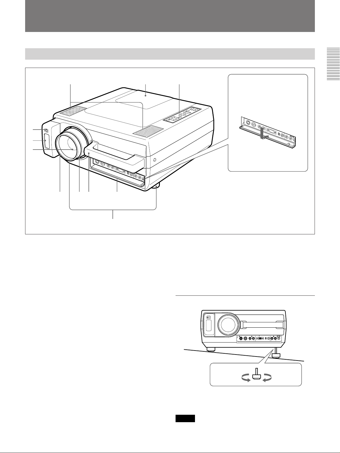
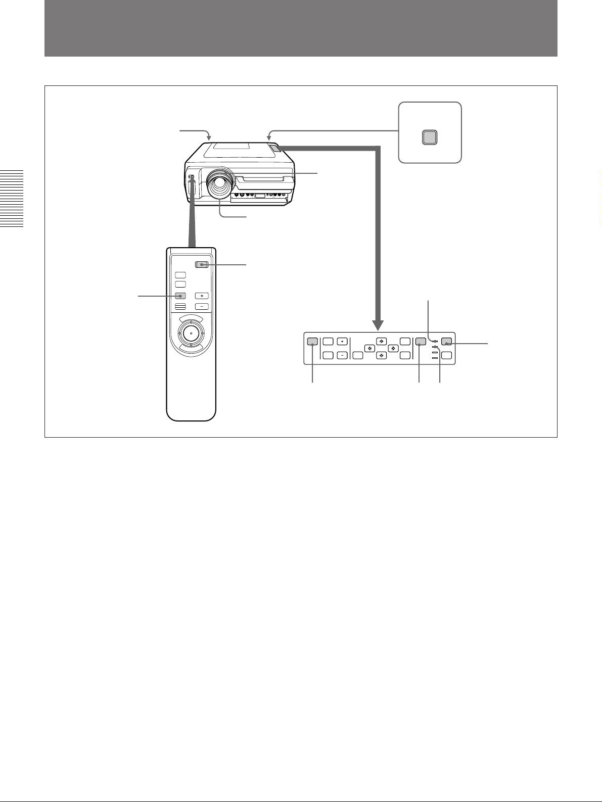
Location and Function of Controls
Front
1!¡!º
2
3
4
567 9
8
1 Speakers
2 Front remote control detector
3 Remote Commander pocket
Houses the supplied Remote Commander. When
inserting the Remote Commander, make sure the
infrared transmitter is facing forwards and push it until
it clicks.
To take out the Remote Commander from the pocket,
push it once and pull it out.
How to open and close the
connector cover
To open the cover, pull it
down.
To close the cover, pull it up
until it locks.
9 Connector panel
For details, see page 9.
0 Control panel
For details, see page 8.
!¡ Lamp cover
How to use the adjusters
4 Lens
Remove the lens cap before projection.
5 Focus ring
Adjusts the picture focus.
6 Zoom ring
Adjusts the size of the picture.
7 Carrying handle
Use the handle for carrying the projector.
8 Adjusters
Use the adjusters to keep the projector level if it is
installed on an uneven surface.
To lower
the projector
To raise
the projector
While lifting the projector, turn the adjusters and
adjust the height so that the projector becomes level.
Note
Be careful not to let the projector down on your
fingers.
7 (EN)
Page 8
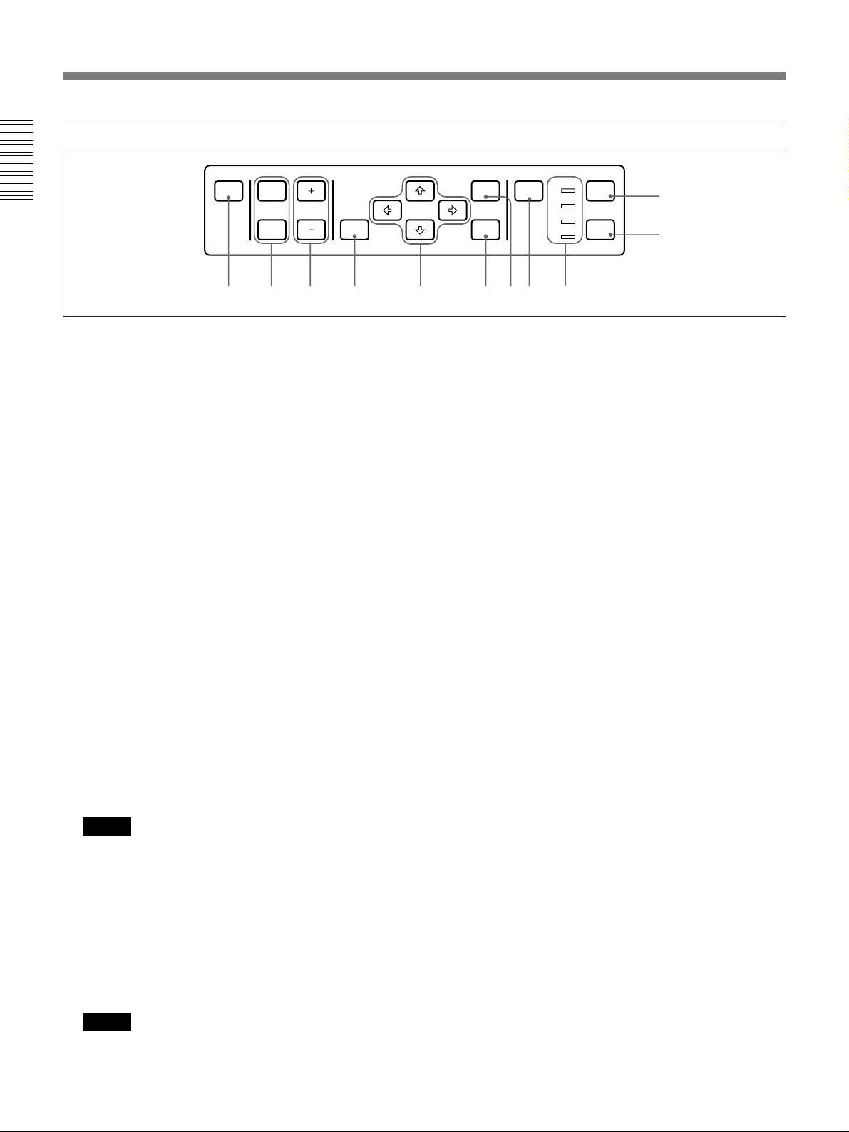
Location and Function of Controls
Control panel
PATTERN PICTURE
MUTING VOLUME
AUDIO LIGHT
RESET
MENU
ENTER
INPUT
SELECT
POWER
STANDBY
u
3456789!º!¡
LAMP
TEMP
POWER
1
2
1 POWER key
Press to turn the projector on and off once the
projector is in the standby mode. The POWER
indicator lights in green when the power is turned on.
When turning off the power, press and hold the
POWER key for about one second.
2 LIGHT key
Lights the back lighting (orange) for the control panel
when the power is turned on. Press again to turn off
the back lighting.
3 Indicators
POWER: Lights in green when the power is turned
on.
Flashes in green while the cooling fan runs after
turning off the power with the POWER key. The
fan runs for about 10 minutes after turning off the
power.
The POWER indicator flashes quickly for the first
minute. During this time, you will not be able to
turn the power back on with the POWER key.
STANDBY: Lights in red when the MAIN POWER
switch at the rear of the projector is turned on.
Once in the standby mode, you can turn the
projector on and off with the POWER key on the
control panel or the Remote Commander.
Note
When the MAIN POWER switch is turned off,
there will be a slight delay before the indicator goes
off.
LAMP: Lights up or flashes under the following
conditions:
• Lights up when a trouble has prevented the lamp
from lighting.
• Flashes when the lamp cover or air filter cover is
not secured firmly.
Note
When the LAMP indicator lights up, never open the
lamp cover if the projector is installed on the
ceiling.
8 (EN)
TEMP (Temperature): Lights up or flashes under
the following conditions:
• Lights up when temperature inside the projector
becomes unusually high.
• Flashes when the fan inside the projector stops.
For details on the LAMP and the TEMP indicators, see page 32.
4 INPUT SELECT key
Selects the input signal. Each time the key is pressed,
the video signal is switched between the VIDEO IN
and INPUT A connectors and the audio signal is
switched between the AUDIO IN L/R and INPUT A
connectors.
5 MENU key
Press to display the on-screen menu. Press again to
clear the menu.
6 ENTER key
Press to enter the settings of items in the menu system.
7 Arrow keys (V/v/B/b)
Used to move the on-screen cursor or to make various
adjustments.
8 RESET key
Press to restore the value of an item back to its factory
preset value. This key functions when the menu or a
setting item is displayed on the screen.
9 VOLUME +/– keys
Adjust the volume of the built-in speakers and output
level of the AUDIO OUT connectors.
+ : Increases the volume.
– : Decreases the volume.
0 MUTING keys
Cuts off the picture and sound.
PICTURE: Press to cut off the picture. Press again
to restore the picture.
AUDIO: Press to cut off the sound. Press again or
press the VOLUME + key to restore the sound.
!¡ PATTERN key
Display a pattern on the screen for focus adjustment.
Press again to clear the pattern.
Page 9
Connector panel
S VIDEO VIDEO
VIDEO IN AUDIO IN
12 34 5
1 VIDEO IN connectors
S VIDEO (mini DIN 4-pin): Connects to the S video
output (Y/C video output) of a video equipment.
VIDEO (BNC-type): Connects to the composite
video output of video equipment.
Note
If you have video equipments connected to both the S
VIDEO and VIDEO connectors, the signal from the S
VIDEO is selected. When showing video connected to
the VIDEO connector, be sure not to connect a cable to
the S VIDEO connector.
L (MONO) R
INPUT A
AUDIO IN
LR
AUDIO OUT
CONTROL S IN
75Ω
ON
OFF
4 AUDIO OUT L/R jacks (phono type)
Connects to external active speakers.
The volume of the speakers can be controlled by the
VOLUME keys on the projector or the Remote
Commander.
5 CONTROL S IN/PLUG IN POWER (DC 5V)
jack (stereo minijack)
Connects to the CONTROL S OUT jack of the
supplied Remote Commander when using as a wired
Remote Commander.
2 AUDIO IN L (MONO)/R jacks (phono type)
Connect to the audio output jacks of an equipment. For
stereo equipment, use both the L and R jacks; for
monaural equipment, use the L (MONO) jack only.
3 INPUT A connectors
RGB input connector (HD D-sub 15-pin, female):
Connect to the monitor output connector on a
computer using the supplied cable. Use the
optional cable to input a component signal.
75-ohm termination switch (ON/OFF): Normally
set to ON. Set it to OFF when the projector is
connected to a computer and a monitor.
AUDIO IN jacks (stereo minijack): Connects to the
audio output jack on a computer.
9 (EN)
Page 10
Location and Function of Controls
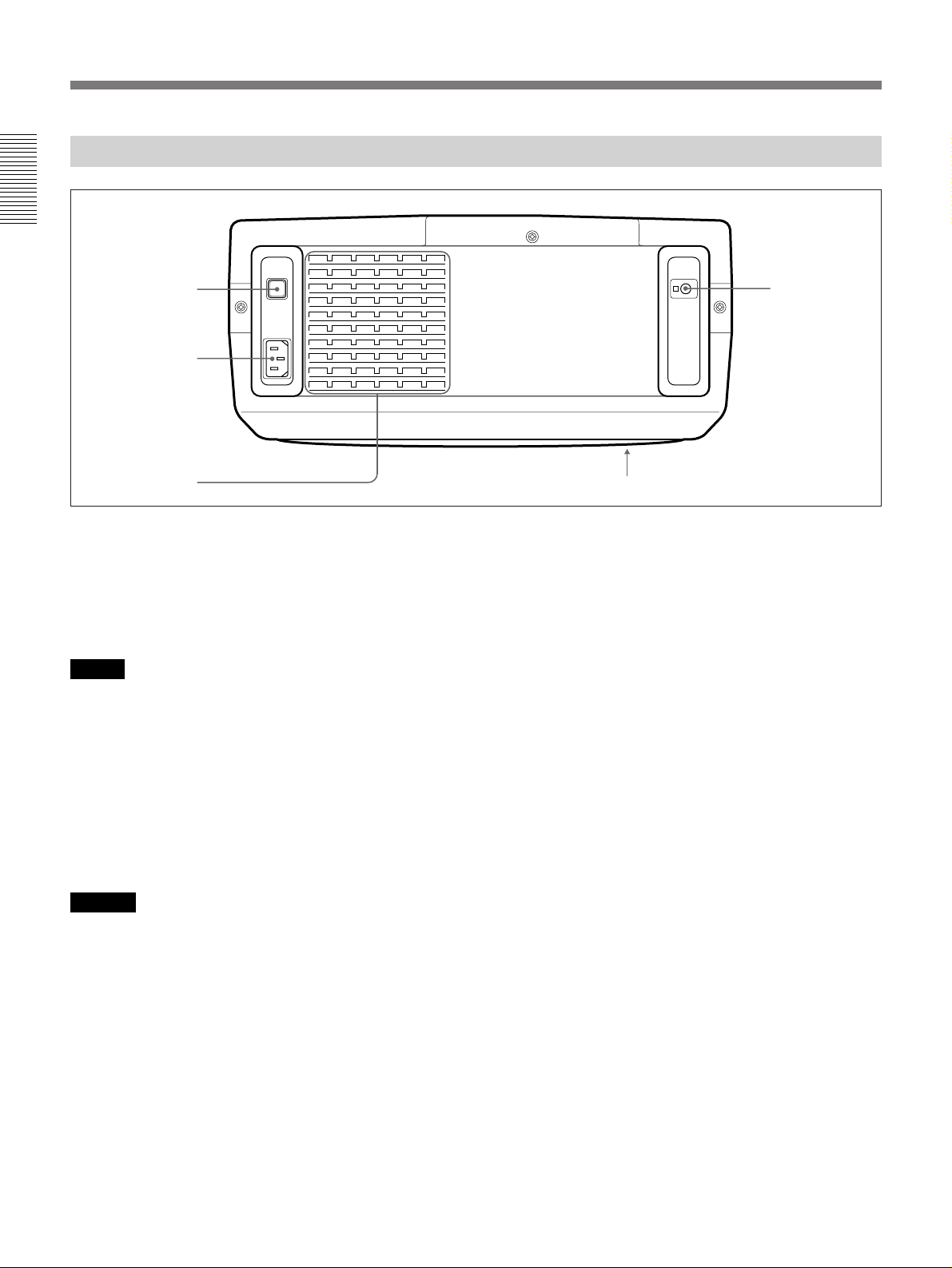
Rear
1
2
3
1 MAIN POWER switch (OON/oOFF)
Turns the main power on and off.
2 AC IN socket
Connect the supplied AC Power cord.
Note
If the supplied AC power cord plug does not match the
wall socket in your country, consult qualified Sony
personnel.
5
4
3 Ventilation holes (exhaust)
4 Ventilation holes (intake)
5 Rear remote control detector
Notes
•Do not place anything near the ventilation holes as it
may cause internal heat build-up.
•Do not place your hand or objects near the ventilation
holes – the air coming out is hot.
10 (EN)
Page 11
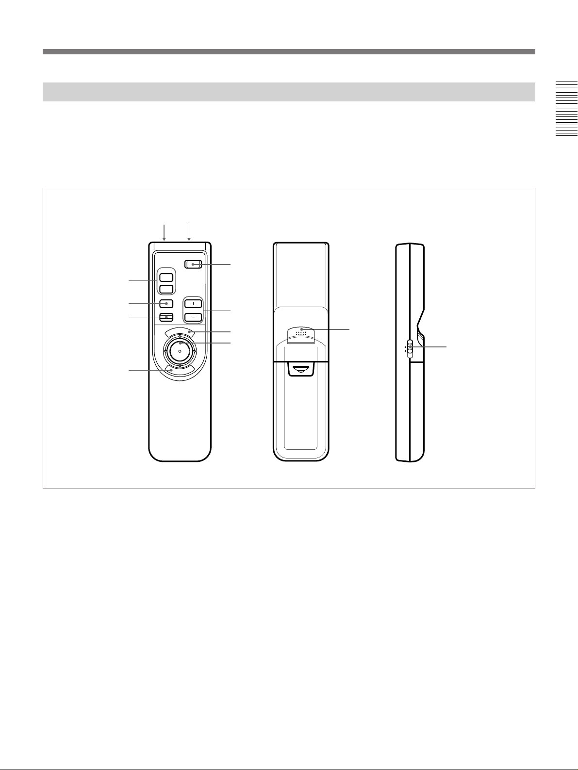
Remote Commander
The Remote Commander may be used as a wireless or
wired Remote Commander.
For details on operation of the keys not mentioned
here, see the description in the control panel section.
9!º
8
7
6
MUTING
PIC
AUDIO
INPUT
POWER
VOLUMERESET
N
U
E
M
1
2
3
4
E
R
N
E
5
T
If you connect the mouse receiver to a computer, you
can use the Remote Commander as a mouse for a
connected computer.
For details, see “Operating a Computer from the Remote
Commander” on page 15.
5
!¡
MOUSE MENU
Front
1 POWER key
2 VOLUME +/– keys
3 MENU key
4 Joy stick
Used to move the on-screen cursor or to make various
adjustments.
5 ENTER keys
6 RESET key
7 INPUT key
8 MUTING PIC/AUDIO keys
The MUTING PIC key has the same function as the
MUTING PICTURE key on the control panel.
Rear
Side
9 CONTROL S OUT connector (stereo minijack)
Connect to the CONTROL S IN connector on the
projector when using the Remote Commander as a
wired Remote Commander. When using the Remote
Commander as a wired Remote Commander by
connecting a stereo remote commander cable, you do
not need to install the batteries since the power is
supplied from the CONTROL S IN jack on the
projector.
0 Infrared transmitter
!¡ MOUSE/MENU switch
Normally, set to MENU.
Set to MOUSE when you operate the mouse on a
computer connected to the mouse receiver from the
Remote Commander.
For details, see “Operating a Computer from the Remote
Commander” on page 15.
11 (EN)
Page 12
Location and Function of Controls
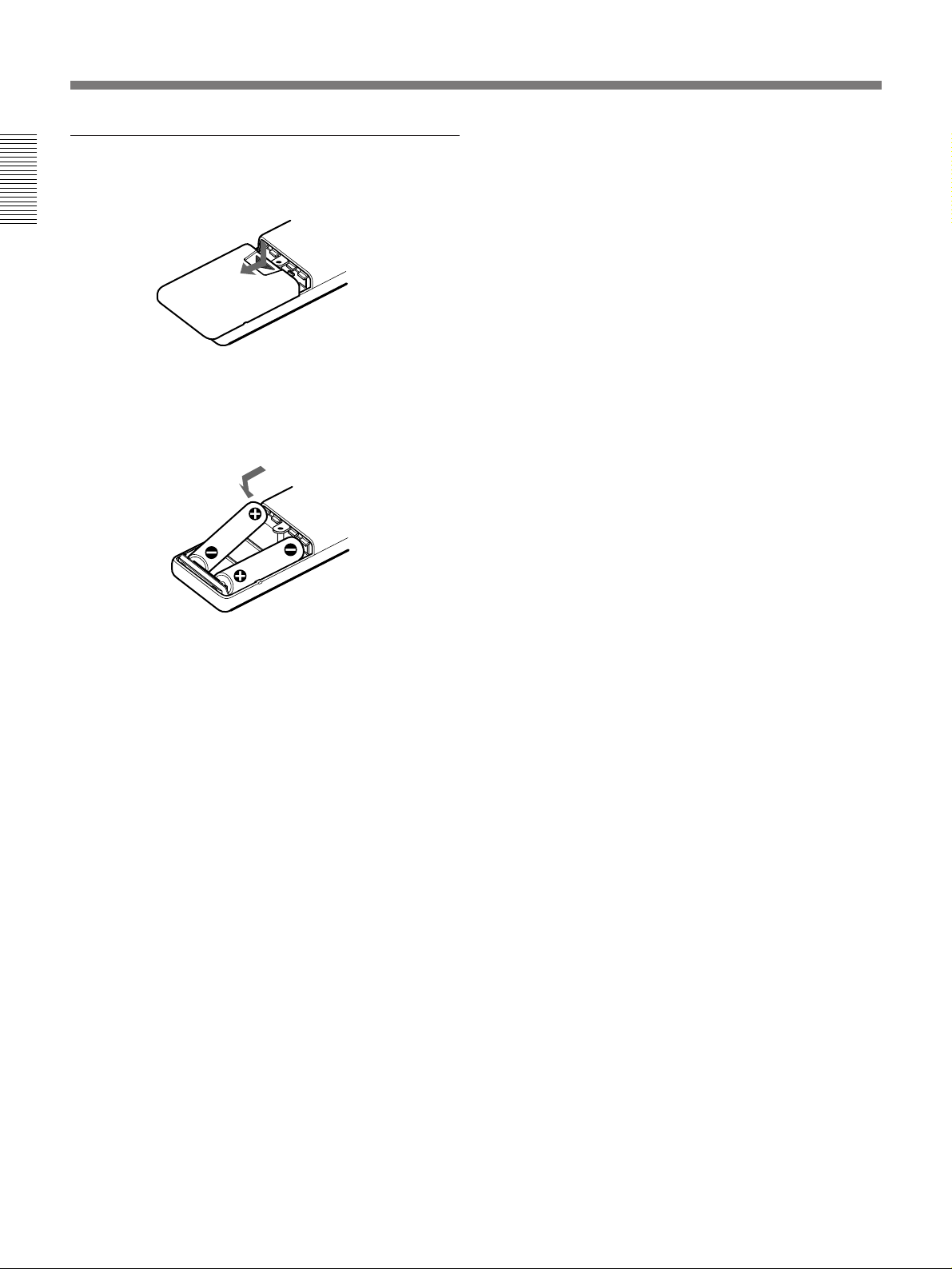
Battery installation
1 Push and slide to open the lid.
2 Install the two size AA (R6) batteries (supplied)
with the correct polarity.
Be sure to install
the battery from
the ’ side.
•The remote control detectors on the projector do not
operate when the Remote Commander is being used
as a wired Remote Commander. If you wish to use
the Remote Commander as a wireless Remote
Commander, be sure to remove the connecting cable
from both the Remote Commander and the projector.
3 Replace the lid.
Notes on batteries
•Be careful that the battery orientation is correct when
inserting batteries.
•Do not mix old battery with new one, or different
types of batteries.
•If you do not intend to use the Remote Commander
for a long time, remove the batteries to avoid damage
from battery leakage. If a battery has leaked, remove
the batteries, wipe the battery compartment dry and
replace the batteries with new ones.
Notes on wireless Remote Commander
operation
•Be sure that there is nothing to obstruct the infrared
beam between the Remote Commander and the
projector.
•The operation range is limited. The shorter the
distance between the Remote Commander and the
projector, the wider the angle within which the
commander can control the projector.
12 (EN)
Page 13
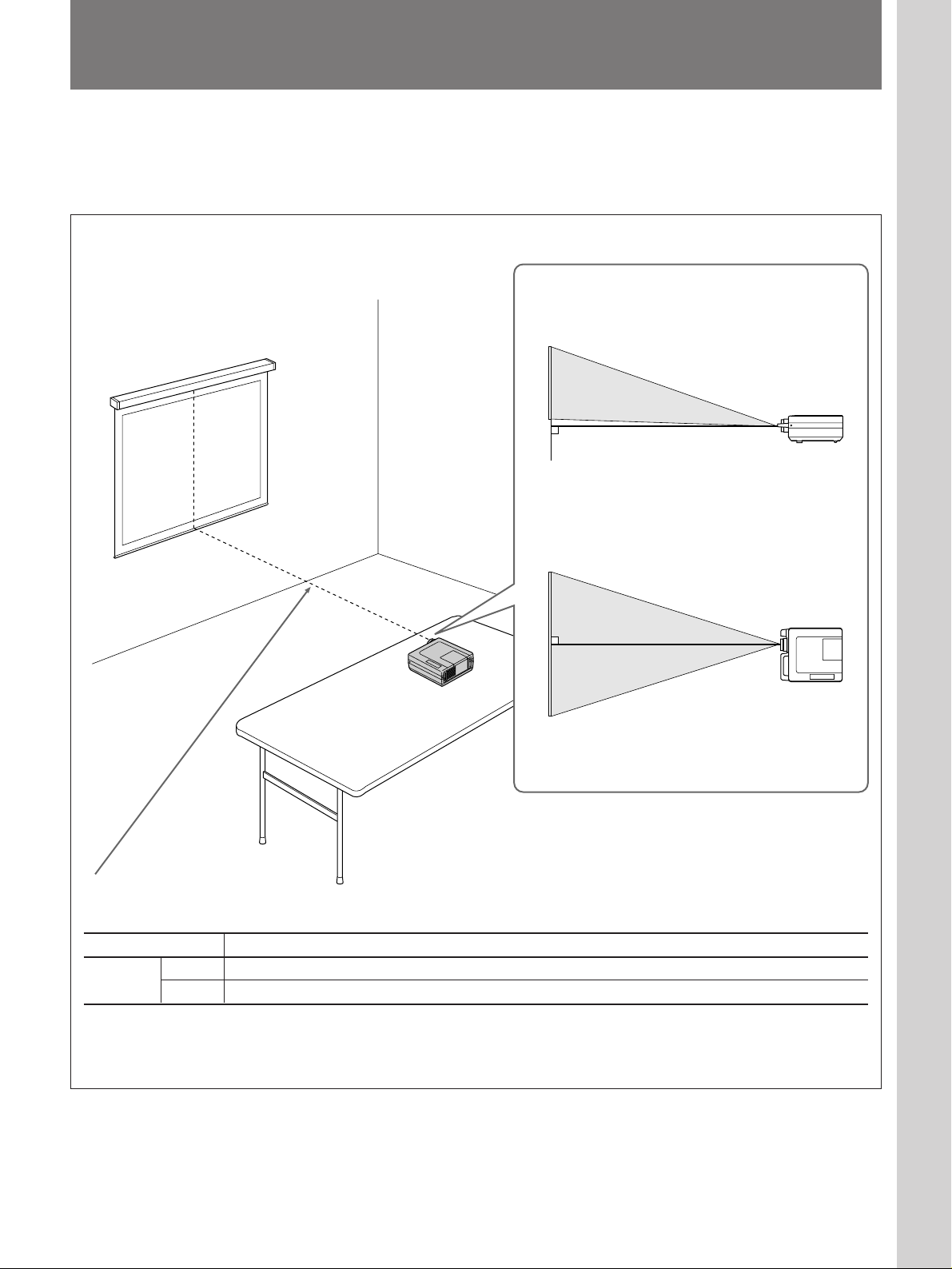
Installing the Projector
This section describes the installation arrangements for installing the
projector on a table. For ceiling installation, consult with qualified Sony
personnel (see page 29).
Horizontal center
of the screen
Setting up and projecting
Adjust the vertical and horizontal positioning of the
projector.
Vertical positioning (side view)
Adjust the height of the projector so that the center of
the lens is just below the bottom edge of the screen.
Horizontal positioning (top view)
Adjust the horizontal positioning of the projector so
that the lens is aligned with the horizontal center of the
screen.
The distance between the lens and the
screen varies depending on the size of the
screen. Use the following table as a guide.
Screen size (inches) 40 60 80 100 120 150 180 200 250 300
Distance
Minimum 1.5 (4.9) 2.3 (7.5) 3.1 (10.1) 3.9 (12.7) 4.7 (15.4) 5.9 (19.3) 7.1 (23.2) 7.9 (25.8) 9.9 (32.3) 11.9 (38.9)
Maximum 2.3 (7.7) 3.5 (11.5) 4.7 (15.5) 5.9 (19.3) 7.1 (23.3) 8.9 (29.3) 10.7 (35.1) 11.9 (39.2) 15.0 (49.0) 18.0 (58.9)
Unit: m (feet)
For detailed information on installation measurements, see page 28.
13 (EN)
Page 14
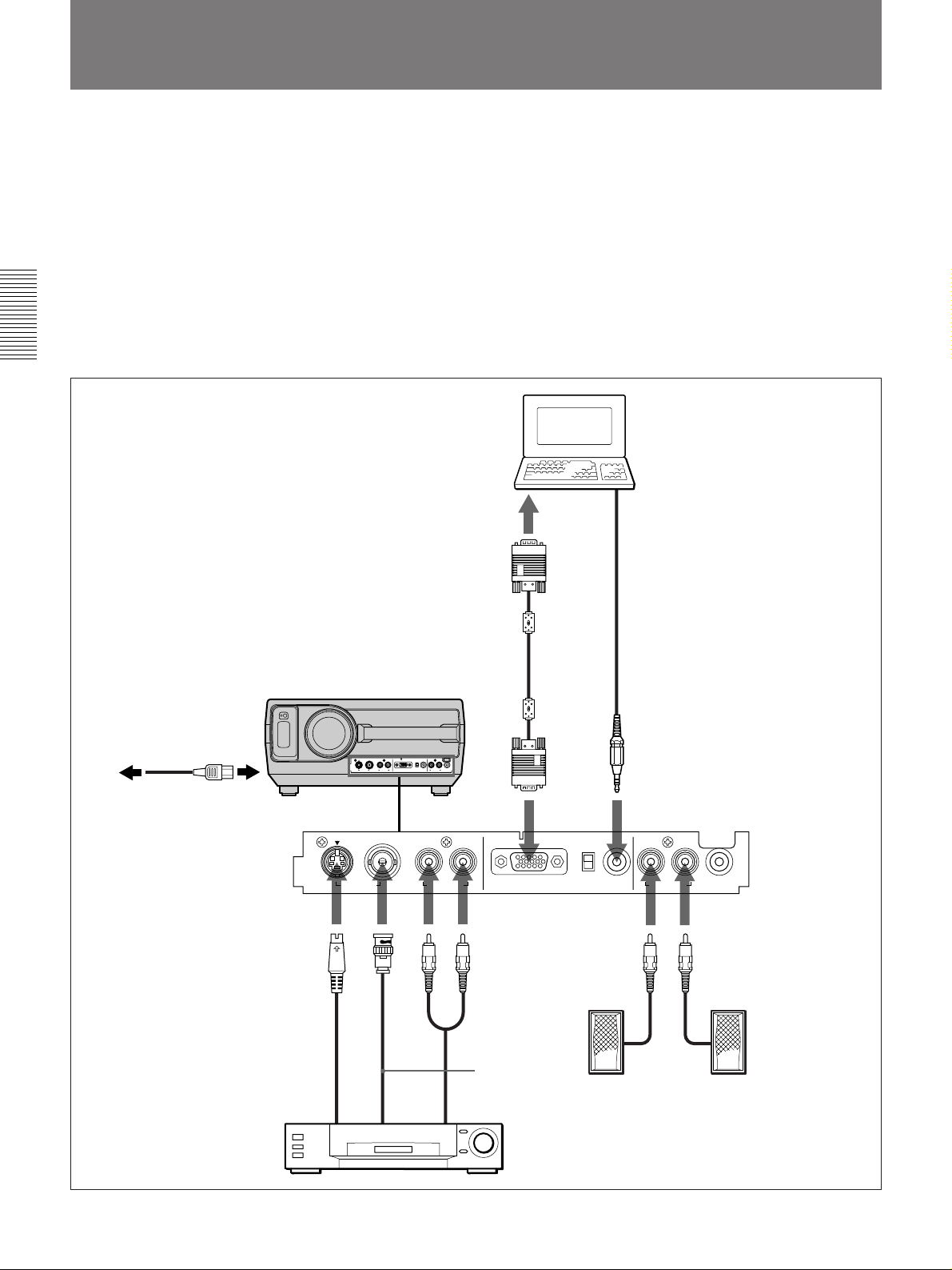
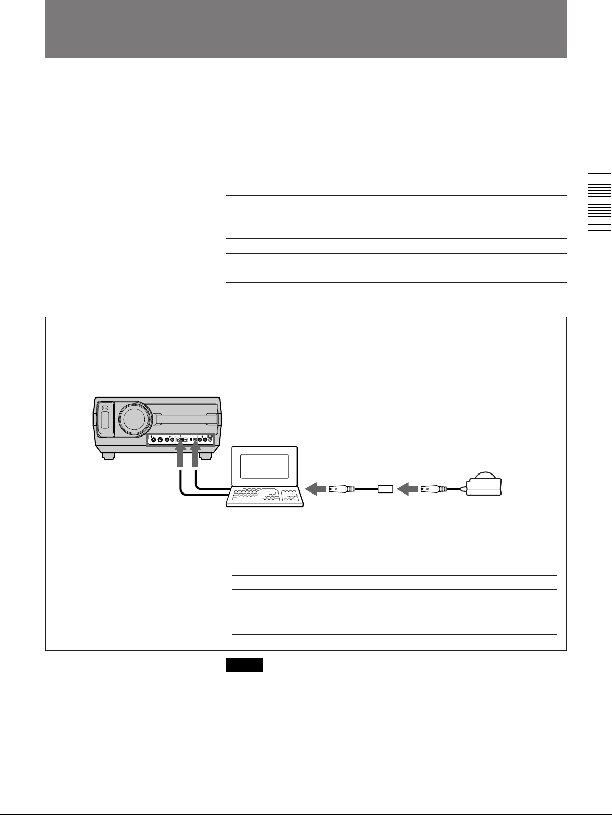
Connecting with a Computer or a VCR
This section describes how to connect the projector with a computer or a
VCR and external active speakers. For details on how to connect other
equipment, see page 30.
Also refer to the instruction manuals of the equipment to be connected.
When making connections, be sure to:
•turn off all equipment before making any connections.
•use the proper cables for each connection.
•insert the plugs of the cables properly; plugs that are not fully inserted
often generate noise. When pulling out a cable, be sure to pull it out from
the plug, not the cable itself.
For details on the DIP switch setting of
the adapter, see page 36.
Use the supplied adapter when
connecting with a Macintosh1) computer.
Computer
to a wall outlet to AC IN
AC power cord
(supplied)
S-Video cable (not supplied)
HD D-sub 15-pin cable (supplied)
Front
S VIDEO VIDEO
VIDEO IN AUDIO IN
L (MONO) R
Audio cable
(not supplied)
INPUT A
OFF
Audio cable (not supplied)
AUDIO IN
LR
AUDIO OUT
CONTROL S IN
75Ω
ON
Video cable
to S VIDEO OUT
VCR
to
VIDEO
OUT
(not supplied)
to AUDIO OUT
Active speakers
..........................................................................................................................................................................................................
14 (EN)
1) Macintosh is a registered trademark of Apple Computer, Inc.
Page 15
Operating a Computer from the Remote Commander
If you connect the supplied mouse receiver to the mouse port of a
computer, you can operate the mouse function of a computer with the
Remote Commander.
Set the MOUSE/MENU switch to MOUSE when you operate a computer
connected to the mouse receiver from the Remote Commander.
When the MENU/MOUSE switch is set to MOUSE, the MENU, ENTER
keys and joy stick on the Remote Commander function as follows.
Key and joy stick
MENU Left button Mouse button
ENTER (front) Right button Mouse button
ENTER (rear) Right button Mouse button
Joy stick Corresponds with the movements of the mouse
When using an IBM PC/AT compatible computer
For details, see the supplied RM-PJ20 operating instructions.
Front
Computer
IBM PC/AT
compatible, NEC
Cable for IBM PC/AT
compatible computer
1)
Function
2)
Macintosh
to mouse port
Use the supplied conversion cable when you
connect to the IBM PC/AT compatible or
Macintosh computer.
Computer
Conversion
cable
NEC
—
IBM PC/AT compatible
Cable for IBM (for PC/AT
compatible computer, PS/2
type)
(6-pin˜9-pin)
Mouse receiver
Macintosh
Cable for
Macintosh
(4-pin˜9-pin)
Note
Be sure that there is nothing to obstruct the infrared beam between the
Remote Commander and the mouse receiver.
..........................................................................................................................................................................................................
1) IBM PC/AT is a registered trademark of International Business Machines Corporation, USA.
2) NEC is a registered trademark of NEC Corporation.
15 (EN)
Page 16
Projecting
Rear remote control
detector
Front remote control
detector
3
MUTING
PIC
AUDIO
INPUT
1
MAIN
POWER
O ON ⁄ o OFF
5
4, 6
POWER
2
VOLUMERESET
N
E
U
M
PATTERN PICTURE
E
N
R
T
E
MUTING VOLUME
RESET
AUDIO LIGHT
4
POWER indicator
POWER
INPUT
MENU
SELECT
STANDBY
u
ENTER
LAMP
TEMP
STANDBY indicator
3
POWER
2
1 Press the MAIN POWER switch on the rear of the projector (O ON).
The STANDBY indicator lights in red and the projector goes into the
standby mode.
2 Press the POWER key on the Remote Commander or the control
panel.
The POWER indicator lights in green.
3 Switch on equipment connected to the projector. Press the INPUT
SELECT key on the control panel or the INPUT key on the Remote
Commander to select the input source.
INPUT A: Selects audio and video signals input from the INPUT A
connectors.
VIDEO: Selects signal input from the VIDEO IN and AUDIO IN L/
R connectors.
(If you have made connections to both the S VIDEO and
the VIDEO connectors, the signal from the S VIDEO
connector is selected.)
16 (EN)
Page 17
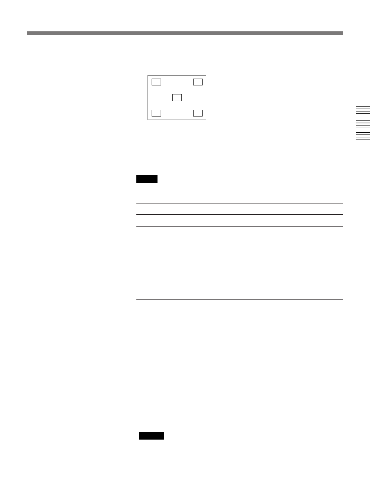
4 Press the PATTERN key on the control panel to display the “H” test
pattern, and turn the focus ring to adjust the focus.
HHHH HHHH
HHHH HHHH
HHHH
HHHH
HHHH HHHH
HHHH HHHH
Press the PATTERN key again to clear the pattern.
5 Turn the zoom ring to adjust the size of the picture.
6 Turn the focus ring again to adjust the focus.
Note
Do not look into the lens when the projector lamp is on.
To Press
Adjust the volume the VOLUME +/– keys.
Cut off the sound the AUDIO MUTING key. To restore
the sound, press the AUDIO MUTING
key again or press the VOLUME + key.
To turn off the power
Cut off the picture the PICTURE MUTING key (PIC
MUTING key on the Remote
Commander). To restore the picture,
press the PICTURE MUTING key
again.
1 Press and hold the POWER key on the control panel or the Remote
Commander for about one second.
The POWER indicator flashes in green and the fan continues to run for
about 10 minutes to reduce the internal heat. The POWER indicator
flashes quickly for the first minute. During this time, you will not be
able to turn the power back on with the POWER key. After about one
minute, you can turn on the power with the POWER key.
2 Wait until the fan stops running and the STANDBY indicator lights in
red; then press the MAIN POWER switch to turn off the main power
(o OFF).
Notes
• Do not press the MAIN POWER switch while the fan is still
running; the fan will stop while the lamp is still hot, leading to
breakdown.
• To make the lamp life last longer, do not turn off the power at
least for about 10 minutes after turning on the power.
17 (EN)
Page 18
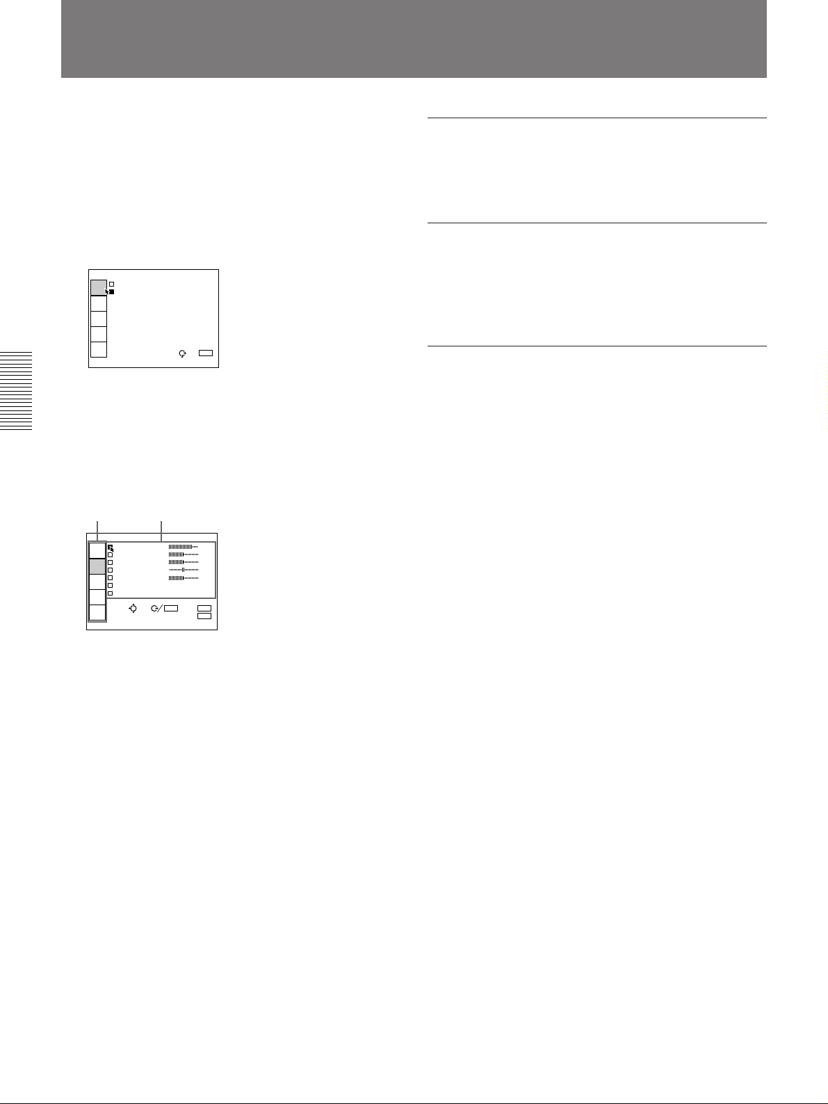
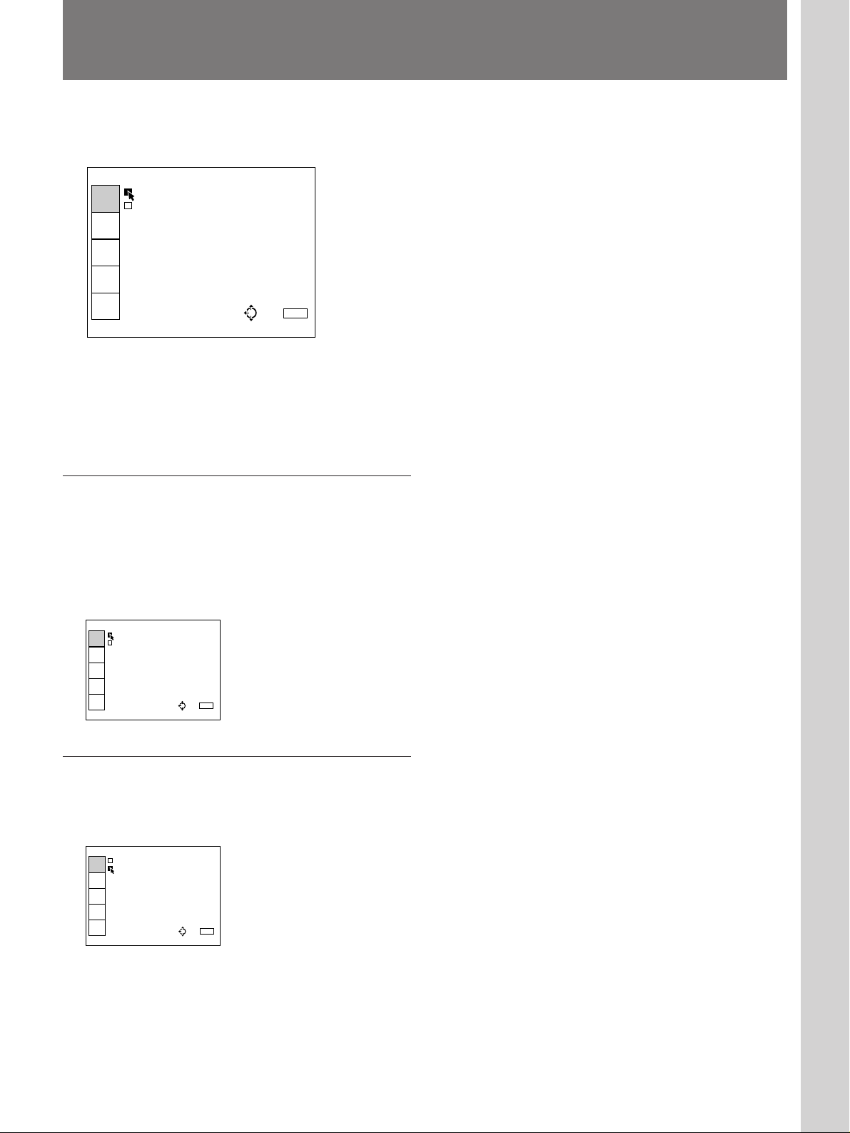
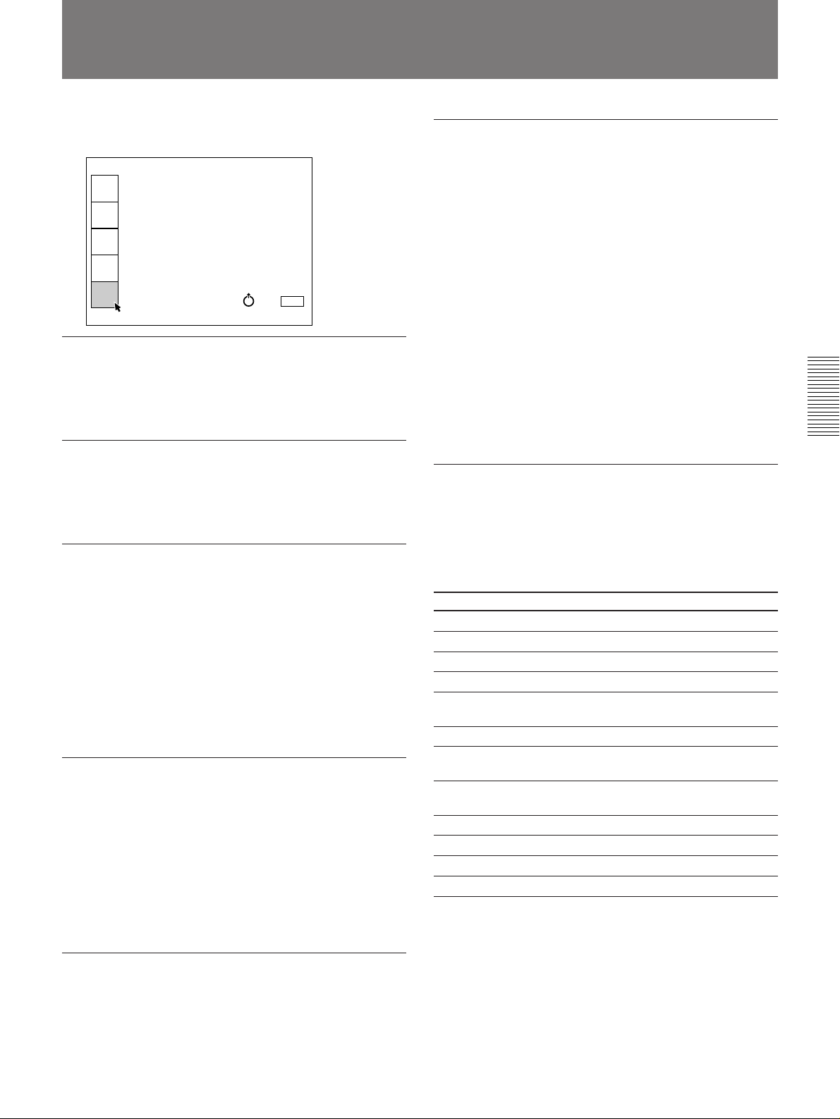
Using the MENU
The projector is equipped with an on-screen menu for
making various adjustments and settings.
To select the language used in the menu, see page
25.
1 Press the MENU key.
The menu display appears.
The menu presently selected is highlighted in blue.
INPUT-A
VIDEO
INPUT
SELECT
INPUT-A
PICTURE
CTRL
INPUT
SETTING
SET
SETTING
INPUT
INFO.
SEL: EXIT: MENU
2 Use the V or v keys on the control panel to select a
menu, then press the b or the ENTER key. On the
Remote Commander, move the joy stick up or
down to select a menu, then move it to the right or
press the ENTER key.
The selected menu appears.
Menus Setting items
To clear the menu display
Press the MENU key. The menu display disappears
automatically if no key is pressed for one minute.
To reset items that have been adjusted
Press the RESET key. “Reset complete!” appears on
the screen and the settings appearing on the screen will
be reset to their factory preset values.
About the memory of the settings
The settings other than the INPUT SETTING menu
are automatically stored in the projector memory.
Adjustments made in the INPUT SETTING menu
have to be saved with the SAVE TO MEMORY item
in the INPUT SETTING menu.
VIDEO
CONTRAST 80
INPUT
SELECT
BRIGHT 50
COLOR 50
PICTURE
CTRL
HUE 50
SHARP 50
INPUT
SETTING
D.PICTURE:OFF
COLOR SYS:AUTO
SET
SETTING
SEL:
INPUT
INFO.
SET: ENTER RESET: RESET
EXIT: MENU
3 Make setting or adjustment on an item.
For details on setting individual items, see the relevant
menu pages.
18 (EN)
Page 19
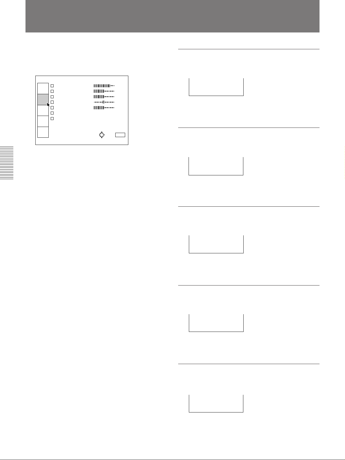
The INPUT SELECT Menu
The INPUT SELECT menu is used for selecting the
input signal.
VIDEO
VIDEO
INPUT
SELECT
INPUT-A
PICTURE
CTRL
INPUT
SETTING
SET
SETTING
INPUT
INFO.
Operation
Use the V or the v key on the control panel to select
the input, then press B key.
On the Remote Commander, move the joy stick up or
down to select the input, then move it to the left.
SEL: EXIT: MENU
Adjustments and settings using the menu
VIDEO
Selects signal input from the VIDEO IN (S VIDEO or
VIDEO) connectors and the AUDIO IN L/R
connectors. If you have equipment connected to both
the VIDEO and the S VIDEO connectors, the S
VIDEO will be selected.
VIDEO
VIDEO
INPUT
SELECT
INPUT-A
PICTURE
CTRL
INPUT
SETTING
SET
SETTING
INPUT
INFO.
SEL: EXIT: MENU
INPUT-A
Selects the audio and video signals input from the
INPUT A connectors.
INPUT-A
VIDEO
INPUT
SELECT
INPUT-A
PICTURE
CTRL
INPUT
SETTING
SET
SETTING
INPUT
INFO.
SEL: EXIT: MENU
19 (EN)
Page 20
The PICTURE CTRL Menu
The PICTURE CTRL menu is used for adjusting the
picture. Items which can be adjusted are displayed in
green.
VIDEO
CONTRAST 80
INPUT
SELECT
BRIGHT 50
COLOR 50
PICTURE
CTRL
HUE 50
SHARP 50
INPUT
SETTING
D.PICTURE:OFF
COLOR SYS:AUTO
SET
SETTING
INPUT
INFO.
SEL: EXIT: MENU
Operation
1. Select an item
Use the V or the v key on the control panel to select
the item, then press the b or the ENTER key.
On the Remote Commander, move the joy stick up or
down to select the item, then move it to the right or
press the ENTER key.
CONTRAST
Adjusts the picture contrast.
CONTRAST: 80
The higher the setting, the greater the contrast.
The lower the setting, the lower the contrast.
BRIGHT
Adjusts the picture brightness.
BRIGHT: 50
The higher the setting, the brighter the picture.
The lower the setting, the darker the picture.
COLOR
2. Adjust an item
• When changing the adjustment level:
To increase the number, press the V or the b key.
On the Remote Commander, move the joy stick up
or to the right.
To decrease the number, press the v or the B key.
On the Remote Commander, move the joy stick
down or to the left.
Press the ENTER key to restore the original screen.
• When changing the setting:
Press the V or the v key on the control panel to
change the setting.
On the Remote Commander, move the joy stick up
or down to change the setting.
To restore the original screen, press the ENTER or
the B key.
On the Remote Commander, move the joy stick to
the left.
Adjusts color intensity.
COLOR: 50
The higher the setting, the greater the intensity.
The lower the setting, the lower the intensity.
HUE
Adjusts skin tones.
HUE: 50
A higher the setting, the picture becomes greenish.
A lower the setting, the picture becomes purplish.
SHARP
Adjusts the picture sharpness.
20 (EN)
SHARP: 50
The higher the setting, the sharper the picture.
The lower the setting, the softer the picture.
Page 21
D. (Dynamic) PICTURE
Emphasizes the black color.
VIDEO
CONTRAST 80
INPUT
SELECT
BRIGHT 50
COLOR 50
PICTURE
CTRL
HUE 50
SHARP 50
INPUT
SETTING
D.PICTURE: ON
COLOR SYS: OFF
SET
SETTING
SEL:
INPUT
INFO.
SET: ENTER RESET: RESET
EXIT: MENU
ON: Emphasizes the black color to produce a bolder
“dynamic” picture.
OFF: Reproduces the dark portions of the picture
accurately, in accordance with the source signal.
COLOR SYS (System)
Selects the color system of the input signal.
VIDEO
CONTRAST 80
INPUT
SELECT
BRIGHT 50
COLOR AUTO
PICTURE
CTRL
HUE NTSC3.58
SHARP PAL
INPUT
SETTING
D.PICTURE: SECAM
COLOR SYS: NTSC4.43
SET
SETTING
PAL-M
SEL:
INPUT
INFO.
SET: ENTER RESET: RESET
EXIT: MENU
Normally, set to AUTO.
If the picture is distorted or colorless, select the color
system according to the input signal.
Items cannot be adjusted depending on
the types of input signal
Item Cannot be adjusted with
COLOR Signal input from INPUT A connectors,
HUE Input signal other than NTSC 3.58/4.43
SHARP RGB signal
D. PICTURE RGB signal
COLOR SYS Signal input from INPUT A connectors
black-and-white signal
21 (EN)
Page 22
The INPUT SETTING Menu
The INPUT SETTING menu is used to adjust the input
signal. Items which can be adjusted are displayed in
green.
INPUT-A
DOT PHASE: 48
INPUT
SELECT
SIZE H: 800
SHIFT H:123 V:123
PICTURE
CTRL
FILTER:OFF
CLAMP:AUTO
INPUT
SETTING
COLOR TEMP:HBM
SET
SETTING
SAVE TO MEMORY
INPUT
INFO.
SEL: EXIT: MENU
For details on initial setting signals, see page 38.
Operation
1. Select an item
Use the V or v key on the control panel to select the
item, then press the b or the ENTER key.
On the Remote Commander, move the joy stick up or
down to select the item, then move it to the right or
press the ENTER key.
2. Adjust an item
• When changing the adjustment level:
To increase the number, press the V or the b key.
On the Remote Commander, move the joy stick up
or to the right.
To decrease the number, press the v or the B key.
On the Remote Commander, move the joy stick
down or to the left.
Press the ENTER key to restore the original screen.
DOT PHASE
Adjusts the dot phase of the LCD panel and the signal
input from INPUT A.
DOT PHASE: 48
SIZE
Adjusts the horizontal size of pictures input from
INPUT A.
SIZE H: 800
The higher the setting, the larger the horizontal size of
the picture.
The lower the setting, the smaller the horizontal size of
the picture. Adjust the setting according to the
horizontal dots of the input signal.
Input signal Setting
VGA 800
Macintosh13-inch mode 864
15k RGB 800
1)
VESA
72 Hz (640×480 dots) 832
S VGA VESA 56 Hz 819
S VGA VESA 60 Hz 844
SHIFT
• When changing the setting:
Press the V or the v key to change the setting.
On the Remote Commander, move the joy stick up
or down to change the setting.
To restore the original screen, press the ENTER or
Adjusts the position of the picture input from INPUT
A.
SHIFT H:123 V:123
the B key.
On the Remote Commander, move the joy stick to
the left.
H adjusts the horizontal position of the picture.
V adjusts the vertical position of the picture.
As the setting for H increases, the picture moves to the
right, and as the setting decreases, the picture moves to
the left.
As the setting for V increases, the picture moves up,
and as the setting decreases, the picture moves down.
Use the B or the b key to adjust the horizontal position
and the V and v key for the vertical position.
.........................................................................................................................................................................................................
22 (EN)
1) VESA is a registered trademark of Video Electronics Standard Association.
Page 23
FILTER
INPUT-A
DOT PHASE: 48
SIZE H:800
SHIFT H:123 V:123
FILTER:OFF
CLAMP:AUTO
COLOR TEMP: HIGH
LOW
SAVE TO MEM HBM
INPUT
SELECT
PICTURE
CTRL
INPUT
SETTING
SET
SETTING
INPUT
INFO.
EXIT: MENU
SEL:
SET: ENTER RESET: RESET
INPUT-A
DOT PHASE: 48
SIZE H:800
SHIFT H:123 V:123
FILTER:OFF
CLAMP:AUTO
COLOR TEMP:HBM
SAVE TO MEMORY
INPUT
SELECT
PICTURE
CTRL
INPUT
SETTING
SET
SETTING
INPUT
INFO.
EXIT: MENU
SEL: SET:
ENTER RESET: RESET
INPUT-A
DOT PHASE: 48
SIZE H:800
SHIFT H:123 V:123
FILTER:OFF
CLAMP:AUTO
COLOR TEMP:HBM
SAVE TO MEMORY
Saving is complete!
INPUT
SELECT
PICTURE
CTRL
INPUT
SETTING
SET
SETTING
INPUT
INFO.
EXIT: MENU
SEL: SET:
ENTER RESET: RESET
COLOR TEMP
Corrects line patterns that appear on the picture input
from INPUT A.
INPUT-A
DOT PHASE: 48
INPUT
SELECT
SIZE H:800
SHIFT H:123 V:123
PICTURE
CTRL
FILTER: ON
CLAMP:A OFF
INPUT
SETTING
COLOR TEMP:HIGH
SET
SETTING
SAVE TO MEMORY
INPUT
INFO.
SET: ENTER RESET: RESET
SEL:
EXIT: MENU
These lines occur when an RGB signal containing
horizontal picture dots other than 640 is input. In such
case, set to ON. The picture will lose some clarity, but
the line patterns will be reduced. Set to OFF to set the
dot number of the input signal to the LCD pixels
number.
CLAMP
Corrects the luminance of the picture input from
INPUT A.
INPUT-A
DOT PHASE: 48
INPUT
SELECT
SIZE H:800
SHIFT H:123 V:123
PICTURE
CTRL
FILTER:OFF
CLAMP: AUTO
INPUT
SETTING
COLOR SonGHBM
H/C
SET
SETTING
SAVE TO MEMORY
INPUT
INFO.
CLAMP is used as a standard for setting the black
level of a picture correctly. The standard position of
the clamp depends on the kind of sync. signal being
used. Normally, the projector CPU judges the signal
and sets the position automatically. However, the CPU
can misjudge the signal because of noise. If the
luminance of the picture seems to be incorrect (too
dark, the black color is too light, or the luminance is
unstable) the clamp position may need to be changed.
SET: ENTER RESET: RESET
SEL:
EXIT: MENU
Adjusts the color temperature.
HIGH: Makes the white color bluish.
LOW: Makes the white color reddish.
HBM (high brightness mode): Reproduces a
picture with high brightness.
SAVE TO MEMORY
You can save the settings in the INPUT SETTING
menu in the projector memory. Whenever a new
setting is saved, the previous settings are overwritten.
Once you have adjusted the settings, select SAVE TO
MEMORY and press the ENTER or the b key. When
the settings have been saved, the message “Saving is
complete!” appears.
AUTO: Automatic setting mode. Normally set to this
position.
SonG: Set to this position if the black seems too
light or greenish.
H/C: Set to this position if the picture is too dark or
luminance is unstable.
Note
If the luminance is still incorrect after changing the
clamp setting, check the input signal and the
connections.
Items cannot be adjusted depending on
the types of input signal
Item Cannot be adjusted with
DOT PHASE Signal input from VIDEO IN connectors
SIZE Signal input from VIDEO IN connectors
FILTER Signal input from VIDEO IN connectors,
component input signal, 15k RGB signal
CLAMP Signal input from VIDEO IN connectors,
component input signal, 15k RGB signal
SHIFT Signal input from VIDEO IN connectors
23 (EN)
Page 24
The SET SETTING Menu
INPUT-A
STATUS: ON
PIC.MUT OFF
AUDIO M ALL OFFF
SPEAKER:ON
INPUT-A:RGB
LANGUAGE:ENGLISH
INPUT
SELECT
PICTURE
CTRL
INPUT
SETTING
SET
SETTING
INPUT
INFO.
SEL: SET: ENTER
EXIT: MENU
RESET: RESET
INPUT-A
STATUS:OFF
PIC.MUTING: ON
AUDIO MUTIN OFFF
SPEAKER:ON
INPUT-A:RGB
LANGUAGE:ENGLISH
INPUT
SELECT
PICTURE
CTRL
INPUT
SETTING
SET
SETTING
INPUT
INFO.
SEL: SET: ENTER
EXIT: MENU
RESET: RESET
INPUT-A
STATUS:OFF
PIC.MUTING:OFF
AUDIO MUTING: ON
SPEAKER:ON OFF
INPUT-A:RGB
LANGUAGE:ENGLISH
INPUT
SELECT
PICTURE
CTRL
INPUT
SETTING
SET
SETTING
INPUT
INFO.
SEL: SET: ENTER
EXIT: MENU
RESET: RESET
The SET SETTING menu is used for changing the
settings of the projector. Items which can be adjusted
are displayed in green.
<page 1>
INPUT-A
STATUS:ON
INPUT
SELECT
PIC.MUTING:OFF
AUDIO MUTING:OFF
PICTURE
CTRL
SPEAKER:ON
INPUT-A:RGB
INPUT
SETTING
LANGUAGE:ENGLISH
SET
SETTING
INPUT
INFO.
SEL: EXIT: MENU
<page 2>
INPUT-A
H POLARITY:NORMAL
INPUT
SELECT
V POLARITY:NORMAL
HALF TONE:OFF
PICTURE
CTRL
POWER SAVING:OFF
SIRCS RECEIVER:
INPUT
SETTING
FRONT&REAR
PATTERN
SET
SETTING
SET: ENTER RESET: RESET
INPUT
INFO.
SEL:
EXIT: MENU
STATUS (on-screen display)
Sets up the on-screen display.
ON: Shows all of the on-screen displays.
OFF: Turns off the on-screen displays except for
“NO INPUT”, “PIC/AUDIO MUTING”, and
warning messages.
ALL OFF: Turns off all of the on-screen displays
except for warning messages.
Note
When you set it to OFF or ALL OFF, the displays for
changing the adjustment level (which are displayed on
one line at the bottom) are not displayed.
PIC. MUTING
The SET SETTING menu consists of two pages.
To change the page, press the v or V the key until the
page changes when selecting an item.
On the Remote Commander, move the joy stick up or
down until the page changes when selecting an item.
Operation
1. Select an item
Use the V or the v key on the control panel to select
the item, then press the b or the ENTER key.
On the Remote Commander, move the joy stick up or
down to select the item, then move it to the right or
press the ENTER key.
2. Change the setting
Press the V or the v key to change the setting.
On the Remote Commander, move the joy stick up or
down to change the setting.
To restore the original screen, press the ENTER or the
B key.
On the Remote Commander, move the joy stick to the
left.
24 (EN)
Set to ON to cut off the picture.
When set to ON, “PIC MUTING” appears on the
screen.
AUDIO MUTING
Set to ON to cut off the sound.
When set to ON, “AUDIO MUTING” appears on the
screen.
Page 25
SPEAKER
INPUT-A
H POLARITY: NORMAL
V POLARITY: REVERSE
HALF TONE:ON
POWER SAVING:OFF
SIRCS RECEIVER:
FRONT&REAR
PATTERN
INPUT
SELECT
PICTURE
CTRL
INPUT
SETTING
SET
SETTING
INPUT
INFO.
SEL: SET: ENTER
EXIT: MENU
RESET: RESET
INPUT-A
H POLARITY:NORMAL
V POLARITY: NORMAL
HALF TONE:O REVERSE
POWER SAVING:OFF
SIRCS RECEIVER:
FRONT&REAR
PATTERN
INPUT
SELECT
PICTURE
CTRL
INPUT
SETTING
SET
SETTING
INPUT
INFO.
SEL: SET: ENTER
EXIT: MENU
RESET: RESET
INPUT-A
H POLARITY:NORMAL
V POLARITY:NORMAL
HALF TONE: ON
POWER SAVI OFFFF
SIRCS RECEIVER:
FRONT&REAR
PATTERN
INPUT
SELECT
PICTURE
CTRL
INPUT
SETTING
SET
SETTING
INPUT
INFO.
SEL: SET: ENTER
EXIT: MENU
RESET: RESET
INPUT-A
H POLARITY:NORMAL
V POLARITY:NORMAL
HALF TONE:OFF
POWER SAVING: ON
SIRCS RECEIVE OFF
FRONT&REAR
PATTERN
INPUT
SELECT
PICTURE
CTRL
INPUT
SETTING
SET
SETTING
INPUT
INFO.
SEL: SET: ENTER
EXIT: MENU
RESET: RESET
H (Horizontal) POLARITY
Set to OFF to cut off the sound of the internal
speakers. When set to OFF, “SPEAKER OFF” appears
on the screen when you turn on the power.
INPUT-A
STATUS:OFF
INPUT
SELECT
PIC.MUTING:ON
AUDIO MUTING:OFF
PICTURE
CTRL
SPEAKER: ON
INPUT-A: OFF
INPUT
SETTING
LANGUAGE:ENGLISH
SET
SETTING
INPUT
INFO.
SEL: SET: ENTER
RESET: RESET
EXIT: MENU
INPUT-A
Selects the RGB or COMPONENT signal input from
INPUT A.
INPUT-A
STATUS:OFF
INPUT
SELECT
PIC.MUTING:ON
AUDIO MUTING:OFF
PICTURE
CTRL
SPEAKER:ON
INPUT-A: RGB
INPUT
SETTING
LANGUAGE COMPONENT
SET
SETTING
SEL: SET: ENTER
INPUT
INFO.
Note
If the setting is not correct, “Frequency is out of
range!” appears on the screen and the color of the
picture becomes strange or the picture is not displayed.
RESET: RESET
EXIT: MENU
Set to REVERSE to reverse the horizontal orientation
of the picture.
V (vertical) POLARITY
Set to REVERSE to reverse the vertical orientation of
the picture.
HALF TONE
Set to ON to reduce the luminance of the menu
background.
LANGUAGE
Selects the language used in the menu and on screen
displays.
INPUT-A
STATUS:OFF
INPUT
SELECT
PIC.MUTIN ENGLISH
AUDIO MUT FRANCAIS
PICTURE
CTRL
SPEAKER:O DEUTSCH
INPUT-A:C ITALIANO
INPUT
SETTING
LANGUAGE: ESPANOL
SET
SETTING
SEL: SET: ENTER
INPUT
INFO.
Available languages are: English, French, German,
Italian, Spanish, Japanese and Chinese.
RESET: RESET
EXIT: MENU
POWER SAVING
When set to ON, the projector goes into the power
saving mode if no signal is input for 10 minutes. The
power saving mode is canceled when a signal is input
or whenever a key is pressed.
(Continued)
25 (EN)
Page 26
The SET SETTING Menu
SIRCS RECEIVER
Selects the remote control detectors on the front and
rear of the projector.
INPUT-A
H POLARITY:NORMAL
INPUT
SELECT
V POLARITY:NORMAL
HALF TONE:OFF
PICTURE
CTRL
POWER SAVING:OFF
SIRCS RECEIVER:
INPUT
SETTING
FRONT&REAR
PATTERN FRONT
SET
SETTING
REAR
SEL: SET: ENTER
INPUT
INFO.
FRONT & REAR: Activates both the front and rear
detectors.
FRONT: Activates the front detector only.
REAR: Activates the rear detector only.
PATTERN
RESET: RESET
EXIT: MENU
Press the b or the ENTER key to display the “H” test
pattern. Press the B or the ENTER key to clear the
pattern. The pattern disappears automatically if no key
is pressed for one minute.
INPUT-A
H POLARITY:NORMAL
INPUT
SELECT
V POLARITY:NORMAL
HALF TONE:OFF
PICTURE
CTRL
POWER SAVING:OFF
SIRCS RECEIVER:
INPUT
SETTING
FRONT&REAR
PATTERN
SET
SETTING
INPUT
INFO.
SEL: SET: ENTER
RESET: RESET
EXIT: MENU
Item cannot be adjusted depending on the
types of input signal
Item Cannot be adjusted with
INPUT-A Signal input from VIDEO IN connectors
26 (EN)
Page 27
The INPUT INFO Menu
The INPUT INFO menu displays the information on a
current input signal.
INPUT-A
fH:31.4kHz
INPUT
SELECT
fV:59.9Hz
H/C SYNC:NEG
PICTURE
CTRL
V-SYNC:NEG
SonG:---
INPUT
SETTING
INPUT SIGNAL:
RGB
SET
SETTING
INPUT MEMORY No.05
INPUT
INFO.
SEL: EXIT: MENU
fH (Horizontal frequency)
Indicates the horizontal frequency of the input signal.
This indication is only used as a reference, this is not
absolute value.
fV (Vertical frequency)
Indicates the vertical frequency of the input signal.
This indication is only used as a reference, this is not
absolute value.
H/C (Horizontal/Composite)-SYNC
Indicates the polarity of the horizontal or the
composite sync. signal. When the picture is being
projected using its sync signal, POS (NEG) is
displayed in green. When the picture is being projected
without using sync signal, POS (NEG) is displayed in
white.
POS: The polarity of the sync. signal is positive.
NEG: The polarity of the sync. signal is negative.
---: No sync. signal is input.
V(Vertical) -SYNC
Indicates the polarity of the vertical sync. signal. When
the picture is being projected using its sync signal,
POS (NEG) is displayed in green. When the picture is
being projected without using sync signal, POS (NEG)
is displayed in white.
POS: The polarity of the sync. signal is positive.
NEG: The polarity of the sync. signal is negative.
---: No sync. signal is input.
SonG
INPUT SIGNAL
Displays the type of current input signal.
NTSC 3.58: NTSC 3.58 input signal from VIDEO
IN
NTSC 4.43: NTSC 4.43 input signal from VIDEO
IN
PAL: PAL input signal from VIDEO IN
SECAM: SECAM input signal from VIDEO IN
PAL-M: PAL-M input signal form VIDEO IN
Y/C: S VIDEO input signal from VIDEO IN
RGB: RGB input signal
COMPONENT: Component input signal
B/W 50: Black and white input signal from VIDEO
IN (vertical frequency: 50 Hz)
B/W 60: Black and white input signal from VIDEO
IN (vertical frequency: 60 Hz)
INPUT MEMORY No.
Indicates the memory number of the INPUT SETTING
data used for current input signal.
Each preset signal is stored in following memory
number.
Memory number Preset signal
01 VIDEO (60 Hz)
02 VIDEO (50 Hz)
03 15k RGB/COMPONENT (60 Hz)
04 15k RGB/COMPONENT (50 Hz)
05 VGA MODE3
(GRAPHICS 640 × 480 dots)
06 VESA 72 Hz (640 × 480 dots)
07 Macintosh 13-inch separate sync
(640 × 480 dots)
08 Macintosh 13-inch S on G
(640 × 480 dots)
09 VGA MODE1 (640 × 350 dots)
10 VGA MODE2 (TEXT 640 × 400 dots)
13 S VGA VESA 56 Hz (800 × 600 dots)
14 S VGA VESA 60 Hz (800 × 600 dots)
When signals other than the preset signals are input
and adjusted in the INPUT SETTING menu, they are
stored in memory numbers 15 to 34.
Indicates the polarity of the Sync on Green. When the
picture is being projected using its sync signal, NEG is
displayed in green. When the picture is being projected
without using sync signal, NEG is displayed in white.
NEG: The polarity of the sync. signal is negative.
---: No Sync. signal is input.
27 (EN)
Page 28
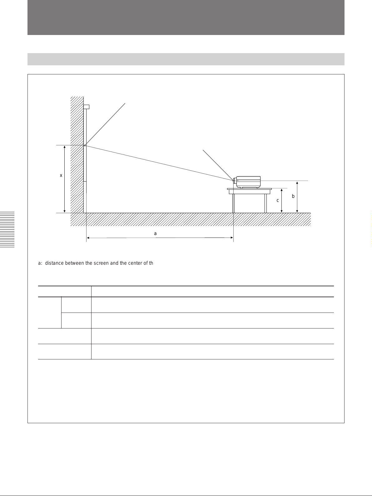
Installation Examples
Floor Installation
Wall
Center of the screen
x
Center of the lens
b
c
Floor
a
a: distance between the screen and the center of the lens
b: distance from the floor to the center of the lens
c: distance from the floor to the foot of the projector
x: free
Screen size (inches) 40 60 80 100 120 150 180 200 250 300
Minimum
a
Maximum
b
c
To calculate the installation measurement (unit: mm)
SS: screen size diagonal (inches)
a (minimum) = (SS–2.59) x 39.82
a (maximum) = (SS–1.84) x 60.26
b = x – (SS/1.3 x 11)
c = x – (SS/1.3 x 11+111)
1490 2290 3090 3880 4680 5870 7070 7860 9860 11850
(58 3/4) (90 1/4) (121 3/4) (152 7/8) (184 3/8) (231 1/8) (278 3/8) (309 1/2) (388 1/4) (466 5/8)
2290 3500 4710 5910 7120 8920 10730 11940 14950 17960
(90 1/4) (137 7/8) (185 1/2) (232 3/4) (280 3/8) (351 1/4) (422 1/2) (470 1/8) (588 5/8) (707 1/8)
x–338 x–508 x–677 x–846 x–1015 x–1269 x–1523 x–1692 x–2115 x–2538
(13 3/8) (20) (26 3/4) (33 3/8) (40) (50) (60) (66 5/8) (83 3/8) (100)
x–449 x–619 x–788 x–957 x–1126 x–1380 x–1634 x–1803 x–2226 x–2649
(17 3/4) (24 3/8) (31 1/8) (37 3/4) (44 3/8) (54 3/8) (64 3/8) (71) (87 3/4) (104 3/8)
Unit: mm (inches)
When converting the number’s unit from mm to inch, divide it by 254.
28 (EN)
Page 29
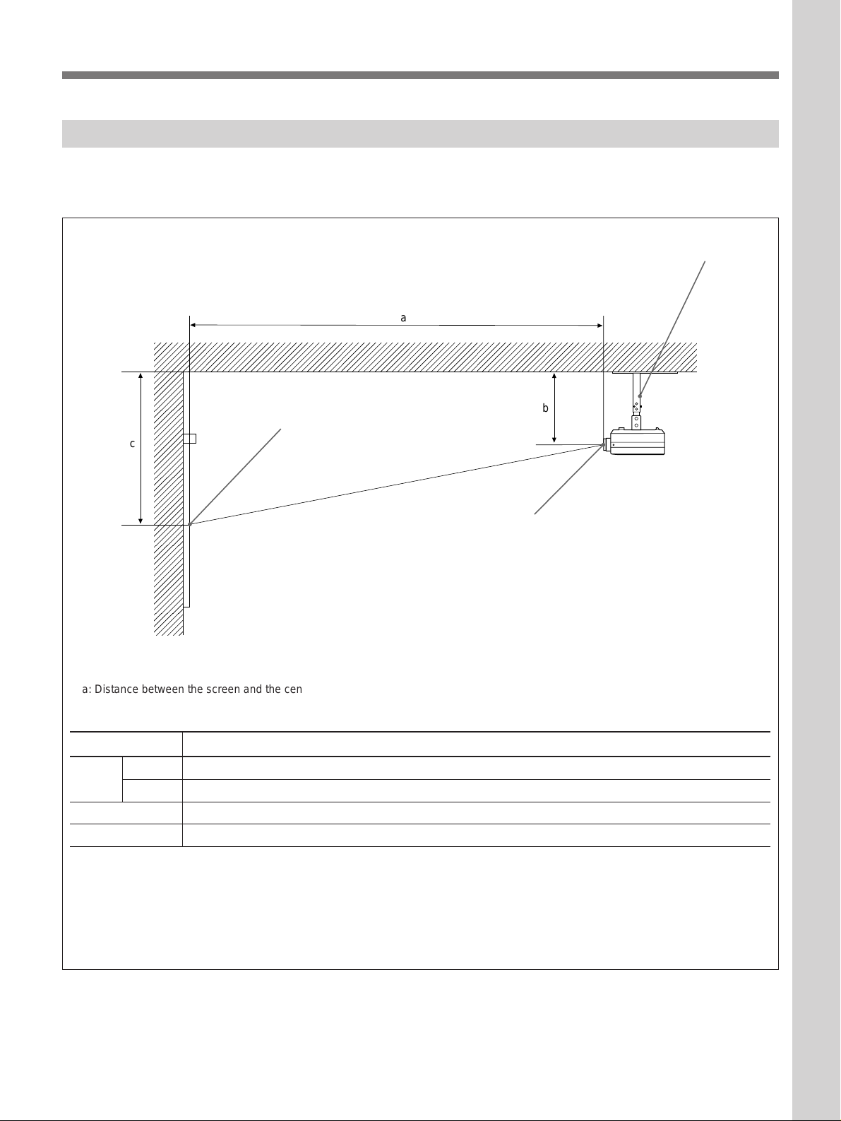
Ceiling Installation
Installation/connection examples
When installing the projector on the ceiling, use the
PSS-500 Projector Suspension Support.
Center of the screen
c
For ceiling installation, consult with qualified Sony
personnel.
PSS-500 Projector Suspension Support
(not supplied)
a
Ceiling
b
Center of the lens
Wall
a: Distance between the screen and the center of lens
b: Distance between the ceiling and the center of the lens
c: Distance between the ceiling and the center of the screen
Screen size (inches) 80 100 120 150 180 200 250 300
a
b 247/272/297/347/372/397 mm (9 3/4 / 10 3/4 / 11 3/4 / 13 3/4 / 14 3/4 / 15 3/4 inches) adjustable
c b+677 (26 3/4) b+846 (33 3/8) b+1015 (40) b+1269 (50) b+1523 (60) b+1692 (66 5/8) b+2115 (83 3/8) b+2538 (100)
To calculate the installation measurement (unit: mm)
SS: screen size diagonal (inches)
a (minimum) = (SS–2.59) x 39.82
a (maximum) = (SS–1.84) x 60.26
c = b + (SS/1.3 x 11)
When converting the number’s unit from mm to inch, divide it by 254.
Minimum 3090 (121 3/4) 3880 (152 7/8) 4680 (184 3/8) 5870 (231 1/8) 7070 (278 3/8) 7860 (309 1/2) 9860 (388 1/4) 11850 (466 5/8)
Maximum 4710 (185 1/2) 5910 (232 3/4) 7120 (280 3/8) 8920 (351 1/4) 10730 (422 1/2) 11940 (470 1/8)14950 (588 5/8) 17960 (707 1/8)
Unit: mm (inches)
29 (EN)
Page 30
Connection Example
For details on how to conncet a computer, a VCR or
Connecting a BNC connector:
external active speakers, see page 14. Also refer to the
instruction manual of the equipment to be connected.
When making connections, be sure to:
•Before connecting any cables, make sure that each
piece of equipment to be connected is turned off.
•Use cables appropriate for the equipment to be
connected.
•A loose connection may cause hum or noise.
•When disconnecting a cable, pull it out from the plug;
not the cable itself.
Connecting 15k RGB/Component Equipment
15k RGB/component equipment to RGB/component output
1 Align the pins with the pin holes and
push in the plug into the socket.
2 Twist to the right.
Front
to a wall outlet to AC IN
AC power cord
(supplied)
S VIDEO VIDEO
VIDEO IN AUDIO IN
L (MONO) R
Notes
• This unit cannot accept separate sync signal with 15k
RGB/component input signal. Use composite sync
(negative) or Sync on Green.
• When inputting a frequency of VGA or an equivalent
from an equipment such as scan-converter, use
separate sync signal.
SMF-400 conversion cable (not supplied)
5X BNC ˜ HD D-sub 15-pin (male)
INPUT A
75Ω
ON
OFF
AUDIO IN
Set the 75-ohm termination
switch to ON.
LR
AUDIO OUT
CONTROL S IN
• This unit cannot accept a interlace signal of VGA or
an equivalent other than 15k RGB/component signal.
• Select the RGB or COMPONENT signal with the
INPUT-A item on the SET SETTING menu.
30 (EN)
Page 31

Maintenance
Maintenance
Replacing the Lamp
When it is time to replace the lamp, the message
“Please replace the LAMP” appears on the screen
when you turn on the projector. Once the message
appears, replace the lamp promptly with a new PK-
1)
PJ500
The message disappears if any key on the control panel
or the Remote Commander is pressd.
• If you continue to use the projector after the message
lamp.
Please replace the LAMP.
Notes
above has appeared, the following message appears.
Cleaning the Air Filter
The air filter should be cleaned every 300 hours. When
it becomes difficult to remove the dust from the filter,
replace the filter with a new one.
To clean the air filter, follow the steps below:
1 Turn off the MAIN POWER switch and unplug the
power cord.
2 Remove the air filter cover on the bottom of the
projector.
Please replace the LAMP.
Possible damage
with continued use!
When this message appears, no key except the
POWER key will be operable.
•After turning off the power, wait at least one hour
before changing the lamp to give it time to cool down
completely.
For details on replacement, refer to the instruction manual
of the lamp.
Note
When the LAMP indicator lights up, never open the
lamp cover if the projector is installed on the ceiling.
3 Remove the air filter.
4 Remove the dust from the filter with a vacuum
cleaner.
5 Attach the air filter and replace the cover.
Notes
•If the air filter is excessively dirty, wash it with a
mild detergent solution and dry it in a shaded place.
•Be sure to attach the air filter cover firmly; the power
will not be turned on if it is not closed securely.
..........................................................................................................................................................................................................
1) PK-PJ500 may not be available in some areas. For details, please consult your nearest Sony office.
31 (EN)
Page 32

Troubleshooting
If the projector appears to be operating erratically, try to diagnose and correct the problem, using the following
guide. If the problem still persists, consult with qualified Sony personnel.
Symptom Cause Remedy
The power is not turned on.
No picture and no sound.
No picture or no sound.
The picture is noisy.
When inputting sound through
INPUT A, sound comes
through one channel only.
Picture from INPUT A is
colored strange.
“Frequency is out of range!”
appears in spite of inputting the
correct signal from INPUT A.
“NO INPUT” appears when
15k RGB or component signal
is input.
On-screen displays do not
appear.
Color balance is incorrect.
Picture is too dark.
Picture is not clear.
Picture luminance is incorrect.
The LAMP indicator lights up.
The LAMP indicator flashes.
The TEMP indicator lights up.
The MAIN POWER switch is turned off.
The power has been turned off and on
with the POWER key at a short internal.
Lamp cover is detached.
Air filter cover is detached.
Cable is disconnected.
Input selection is incorrect.
Either the picture or the sound is cut off.
Noise may appear on the background
depending on the combination of the
numbers of dot input from INPUT A and
numbers of pixel on the LCD panel.
Monaural sound is being input through
the INPUT A connectors.
Setting for INPUT-A in the SET
SETTING menu is incorrect.
Setting for INPUT-A in the SET
SETTING menu is incorrect.
The sync signal is incorrect.
STATUS in the SET SETTING menu has
been set to OFF or ALL OFF.
Picture has not been adjusted properly.
Projector is set to wrong color system.
Lamp is nearing the end of its life.
Contrast or brightness has not been
adjusted properly.
Picture is out of focus.
Condensation has occurred on the lens.
The CLAMP setting is wrong.
A trouble has prevented the lamp from
lighting.
The lamp cover or the air filter cover is
detached.
The internal temperature is unusually
high.
Press the MAIN POWER switch at the rear of the
projector (see page 16).
Wait for about one minute before turning on the
power with the POWER key.
Close the lamp cover securely (see page 31).
Close the air filter cover securely (see page 31).
Check that the proper connections have been
made (see pages 14 and 30).
Select the input source correctly.
Press the MUTING keys to release the muting
function (see page 17).
Change the desktop pattern on the connected
computer.
Input stereo sound.
Select RGB or COMPONENT for INPUT-A in the
SET SETTING menu according to the input signal.
Select RGB or COMPONENT for INPUT-A in the
SET SETTING menu according to the input signal.
Input the correct sync signal (composite sync or
sync on G signal (sync on Y for component
signal)).
Set STATUS in the SET SETTING menu to ON
(see page 24).
Adjust the picture (see pages 20 and 21).
Set the color system in the PICTURE CTRL menu
to match the color system being input.
Change the lamp (see page 31).
Adjust the contrast or brightness properly.
Adjust the focus (see page 17).
Leave the projector for about two hours with the
power on.
Set it correctly in CLAMP in the INPUT SETTING
menu (see page 23).
Replace the lamp. If the projector is installed on
the ceiling, consult with qualified Sony personnel.
Attach the cover securely (see page 31).
Check to see that nothing is blocking the
ventilation holes and leave the projector for about
one hour (see page 10).
32 (EN)
Page 33

Symptom Cause Remedy
The Remote Commander
does not work.
Any key does not function
other than the POWER key.
The Remote Commander batteries are
dead.
The MOUSE/MENU switch has been
switched to the MOUSE position.
You are using the Remote Commander
as a wireless Remote Commander, and
it is connected to the projector.
The unit is influenced of the fluorescent
lamp.
The lamp has reached the end of its life.
Replace with new batteries (see page 12).
Set the switch to MENU position.
Disconnect the cable.
Change the setting of SIRCS RECEIVER in the
SET SETTING menu (see page 26).
Replace the lamp (see page 31).
Notes
•When the LAMP indicator lights up, never open the lamp cover if the projector is installed on the ceiling.
•If the lamp looks damaged when replacing, consult with qualified Sony personnel.
•If the lamp does not light even after replacing it with a new one, consult with qualified Sony personnel.
•If the TEMP indicator starts flashing, consult with qualified Sony personnel.
On-screen messages
Use the list below to check the meaning of the messages displayed on the screen.
Message Meaning Remedy
NO INPUT
Not applicable!
OPERATING
TEMPERATURE TOO HIGH!
This set will be shut down
after 5 minutes
Frequency is out of range!
This input signal cannot be
projected as the frequency is
out of range!
Please replace the LAMP.
No input signal
You have pressed the wrong key.
Operating temperature is too high.
This input signal cannot be projected as
the frequency is out of the acceptable
range of the projector.
You have input RGB signal from the
computer when INPUT-A in the SET
SETTING menu is set to COMPONENT.
The lamp has reached the end of its life.
Check connections
Press the appropriate key.
Turn off the power.
Check to see that nothing is blocking the
ventilation holes.
Input a signal that is within the range of the
frequency.
Set INPUT-A correctly.
Replace the lamp.
33 (EN)
Page 34

Specifications
Specifications
Optical characteristics
Projection system 3 LCD panels, 1 lens, projection
system
LCD panel 1.3-inch TFT LCD panel,
921, 600 pixels (307, 200 pixels
× 3)
Lens 1.6 times zoom lens
f 50 to 80 mm/F 2.5 to 3.1
Lamp 250 W Metal halide lamp
Projection picture size
Range: 40 to 300 inches (diagonal
measure)
1)
Light output ANSI lumen
500 lm
Throwing distance 40-inch: 1490 to 2290 mm
3
/4 to 90 1/4 inches)
(58
80-inch: 3090 to 4710 mm
3
/4 to 185 1/2 inches)
(121
100-inch: 3880 to 5910 mm
7
/8 to 232 3/4 inches)
(152
120-inch: 4680 to 7120 mm
3
/8 to 280 3/8 inches)
(184
200-inch: 7860 to 11940 mm
1
/2 to 470 1/8 inches)
(309
300-inch: 11850 to 17960 mm
5
/8 to 707 1/8 inches)
(466
Electrical characteristics
Color system NTSC/PAL/SECAM/NTSC4.43/
PAL-M system, switched
automatically
Resolution 500 horizontal TV lines (VIDEO
input)
640 × 480 pixels (RGB input)
Acceptable computer signals
15k RGB/component (NTSC)
fH:15.734 kHz, fV:59.94 Hz
15k RGB/component (PAL/
SECAM)
fH:15.625 kHz, fV: 50.0 Hz
VGA MODE1 (640 × 350 dots)
fH:31.468 kHz, fV:70.086 Hz
VGA MODE2
(TEXT 640 × 400 dots)
fH:31.468 kHz, fV:70.086 Hz
VGA MODE3 (GRAPHICS 640 ×
480 dots)
fH:31.468 kHz, fV:59.94 Hz
VGA VESA 72 Hz
(640 × 480 dots)
fH:37.86 kHz, fV:72.809 Hz
Macintosh 13-inch mode
(640 × 480 dots)
fH:35.0 kHz, fV:66.66 Hz
S VGA VESA 56 Hz
(800 × 600 dots)
fH:35.156 kHz, fV:56.25 Hz
S VGA VESA 60 Hz
(800 × 600 dots)
fH:37.879 kHz, fV:60.32 Hz
Horizontal frequency range
RGB:15kHz (S on G/Composite
Sync), 24 to 40 kHz
Vertical frequency range
50 to 70 Hz
Speaker Max. 2W + 2W, 7 × 4 cm
5
/8 × 15 3/4 inches) stereo
(27
Input/Output
VIDEO IN VIDEO: BNC-type
Composite video: 1 Vp-p ±2 dB
sync negative, 75 ohms
terminated
S VIDEO: Mini DIN 4-pin type
Y (luminance): 1 Vp-p ±2 dB
sync negative, 75 ohms
terminated
C (chrominance):burst
0.286 Vp-p ±2 dB (NTSC),
75 ohms terminated
burst 0.3 Vp-p ±2 dB (PAL),
75 ohms terminated
AUDIO IN Phono type:
500 mVrms, stereo, impedance
more than 47 kilohms
INPUT A Analog RGB/component:HD D-
sub15-pin (female) type
(For details, see “Pin assignment”
on page 36.)
R/R-Y: 0.7 Vp-p ±2 dB positive,
75 ohms terminated
G: 0.7 Vp-p ±2 dB positive,
75 ohms terminated
G with sync/Y: 1 Vp-p ±2 dB
sync negative, 75 ohms
terminated
2)
2)
..........................................................................................................................................................................................................
1) ANSI lumen is a measuring method of American National Standard IT 7.215.
34 (EN)
2) Compressed S VGA signal is reproduced.
Page 35

Other
B/B-Y: 0.7 Vp-p ±2 dB positive,
75 ohms terminated
SYNC/HD:
Composite sync: 0.6-8 Vp-p high
impedance, positive/negative
Horizontal sync: 0.6-8 Vp-p high
impedance, positive/negative
VD:
Vertical sync: 0.6-8 Vp-p high
impedance, positive/negative
AUDIO IN: Stereo minijack
500 mVrms, impedance more than
47 kilohms
AUDIO OUT (variable out): Phono type
Max. 1 Vrms, when input is
500 mVrms, impedance less than
5 kilohms
CONTROL S IN/PLUG IN POWER: Stereo minijack
5 Vp-p,
Plug in power, DC 5 V maximum
output 60 mA
Safety regulations VPL-V500Q: UL1950, CSA950,
FCC Class B, IC Class B
VPL-V500QM: EN60 950 (TÜV),
CE
General
Dimensions 368 × 176 × 420 mm (14 1/2 × 7 ×
Mass Approx. 10 kg (22 lb 1 oz)
Power requirements
Power consumption
Heat dissipation 1194.4 BTU
Operating temperature
Operating humidity
Storage temperature
Storage humidity 10% to 90%
5
/8 inches) (w/h/d)
16
VPL-V500Q: AC 100 to 120 V/
220 to 240 V, 50/60 Hz
1)
VPL-V500QM: AC 220 to 240 V,
50/60 Hz
Max. 350 W (Standby mode: 10W)
0°C to 40°C (32°F to 104°F)
35% to 85% (no condensation)
–20°C to 60°C (–4°F to 140°F)
Supplied Accessories
Remote Commander RM-PJM500
(1)
Mouse Receiver RM-PJ20
(Receiver × 1, conversion cable ×
2, Operating Instructions × 1) (1)
Size AA (R6) batteries (2)
HD D-sub 15-pin (male) ˜ HD
D-sub 15-pin (male) cable (1)
Signal Adapter (VGA ˜
Macintosh) (1)
AC Power cord (1)
Lens cap (1)
Operating Instructions (1)
Design and specifications are subject to change
without notice.
Optional accessories
Projector Lamp PK-PJ5002) (for replacement)
Projector Suspension Support PSS-500
Signal Adapter ADP-10 (HD D-sub 15-pin ˜ D-sub
9-pin (for SIC Cable))
Monitor cable
SMF-400 (HD D-sub 15-pin (male) ˜ 5BNC)
SMF-401 (HD D-sub 15-pin (male) ˜ HD D-sub
15-pin (male))
Projection Lens VPLL-FM100
Carrying Case VLC-500
Screens
VPS-100FH (100-inch, flat)
VPS-120FH (120-inch, flat)
Some of the items may not be available in some areas. For
details, please consult your nearest Sony office.
..........................................................................................................................................................................................................
1) UL approved for 120V operation.
2) PK-PJ500 is not available in some areas. For details, please consult your nearest Sony office.
35 (EN)
Page 36

Specifications
Pin assignment
RGB input connector (HD D-sub 15-pin,
female)
1 R/R-Y 9 N.C.
2 G/Y 10 GND
3 B/B-Y 11 GND
4 GND 12 N.C.
5 GND 13 HD/C.Sync
6 GND (R) 14 VD
7 GND (G) 15 N.C.
8 GND (B)
S VIDEO connector (4 pin, mini-DIN)
Chrominance
GND
Luminance
GND
Switch position for adapter
to Macintosh
DIP switch
ON (upper position) = 1
to Projector
Mode fH
VGA 31.5 kHz 00111001
Macintosh 13-inch 35.0 kHz 11 0 0100 1
OFF (lower position) = 0
DIP switch
12345678
36 (EN)
Page 37

Dimensions
Front Rear
Center of the unit
151 (515⁄16)
9 (
)
8
⁄
5
143 (5
11
⁄32)7 (9⁄32)
)111 (4
32
⁄
15
12 (
)
8
⁄
3
67 (2
5
⁄8)
Center of projection balance
25
⁄32)
198 (7
)33 (1
)
16
16
⁄
⁄
5
5
33 (1
)
8
⁄
3
162 (6
)0-20 (0-
16
⁄
15
176 (6
)
32
⁄
25
Bottom Top
Center of the unit
Hole for
attaching the
PSS-500
φ33 (1
5
⁄
16
)
)153 (6
32
⁄
29
150 (5
)
32
⁄
1
305 (12)
67 (25⁄8) 100 (315⁄
5
131.3 (5
⁄32)
Hole for attaching
the PSS-500
16
5
1616
)67 (25⁄8) 100 (315⁄16)
⁄
φ33 (1
Center of projection balance
)
)
2
8
⁄
1
)
32
⁄
31
101 (3
⁄
3
215 (8
187 (7
)
32
⁄
3
)
32
⁄
15
291 (11
)
)
16
⁄
3
4.5 (
)
16
⁄
1
205 (8
)
32
⁄
17
37 (1
420 (16
Center of the unit
144 (521⁄32)
13
⁄16) 145 (523⁄32)
97 (3
)
16
⁄
13
96.8 (3
51 (2)
Center of the unit
148
13
⁄32)
(5
38 (1
35.6
13
(1
Center of projection
balance
3131
152 (5
⁄
3232
1515
⁄
3232
)152 (531⁄32) 150 (529⁄32)
) 37 (1
)
)
16
16
⁄
⁄
9
9
65 (2
65 (2
26
26
(11⁄16)
(11⁄32)
11
⁄32)7 (9⁄32)
9 (
5
16 (
⁄8)
Center of projection balance
⁄16)
1
132 (5
35.6 (1
⁄2)
3
⁄
)137 (5
)
32
32
⁄
⁄
13
13
1616
) 34 (1
1111
137 (5
1515
)
)
16
16
⁄
⁄
9
9
65 (2
65 (2
)
32
⁄
15
12 (
)
8
⁄
7
124 (4
13
⁄32)
)60 (2
)163 (6
8
8
⁄
⁄
3
3
⁄
3232
)132 (53⁄16) 34 (111⁄32)
60 (1
)
)
32
⁄
)
32
⁄
13
32
⁄
13
)
11
32
⁄
15
315 (12
⁄
3232
)37 (115⁄32) 37 (115⁄32)
364.5 (14
418 (16
Hole for attaching the PSS-500
Side
5°
184 (71⁄4)
104 (4
205 (81⁄16)
⁄8)
⁄8)47.5 (147.5 (1
1
1
104.4 (4104.4 (4
3
⁄8)
⁄8) 104.4 (4
7
7
Center of projection balance
47.5 (1
⁄4)
95 (3
)
16
⁄
3
0-5 (0-
φ80 (3
φ80 (3
φ85 (3
φ85 (3
5
5
⁄
3232
)
⁄32)
1111
11
⁄
3232
)
⁄32)
368 (14
1
⁄2)
Unit: mm (inches)
37 (EN)
Page 38

Specifications
Initial setting signals
The projector has been set up to accept the following
signal types.
VGA MODE3 (GRAPHICS) (memory number 05)
640 dots
800 dots
480 lines
525 lines
DATA
SYNC
DATA
SYNC
144 dots
96 dots
35 lines
2 lines
VESA 72 Hz standards (memory number 06)
640 dots
832 dots
480 lines
520 lines
DATA
SYNC
DATA
SYNC
168 dots
40 dots
31 lines
3 lines
Macintosh 13-inch mode (separate sync)
(memory number 07)
640 dots
864 dots
480 lines
525 lines
DATA
SYNC
DATA
SYNC
160 dots
64 dots
42 lines
3 lines
Macintosh 13-inch mode (S on G) (memory
number 08)
64 dots
DATA
160 dots
42 lines
DATA
3 lines
640 dots
864 dots
480 lines
525 lines
VGA MODE1 (memory number 09)
640 dots
800 dots
350 lines
449 lines
DATA
H SYNC
DATA
V SYNC
144 dots
96 dots
62 lines
2 lines
VGA MODE2 (TEXT) (memory number 10)
640 dots
800 dots
400 lines
449 lines
DATA
H SYNC
DATA
V SYNC
144 dots
96 dots
37 lines
2 lines
38 (EN)
Page 39

S VGA VESA 56 Hz (memory number 13)
800 dots
1024 dots
600 lines
625 lines
DATA
H SYNC
DATA
V SYNC
200 dots
72 dots
24
lines
2 lines
S VGA VESA 60 Hz (memory number 14)
800 dots
1056 dots
600 lines
628 lines
DATA
H SYNC
DATA
V SYNC
216 dots
128 dots
27
lines
4 lines
39 (EN)
Page 40

Specifications
Index
A
Adjusters 7
Adjusting
the picture 20
the size/position of the picture 22
the picture luminance (Clamp Setting)
23
Air filter 31
B
Battery
Installation 12
notes 12
C, D, E, F, G, H
Carrying handle 7
Clamp setting 23
Connections
15k RGB/component equipment 30
active speakers 14
a computer 14
power cord 14
VCR 14
Cut off
the picture 17
the sound 17
P, Q
Pin assignment 36
Power
turn on 16
turn off 17
Precautions 4
Projecting a picture 16
R
Remote Commander
notes 12
location and function of controls 11
Resetting the item 18
S
Supplied accessories 35
I, J, K
Input signal selection 16
Installation
on a ceiling 29
on a floor 28
L
Lamp replacement 31
M, N
Menu
INPUT INFO menu 27
INPUT SELECT menu 19
INPUT SETTING menu 22
Operation 18
PICTURE CTRL menu 20
SET SETTING menu 24
O
On-screen display 24
On-screen messages 33
Optional accessories 35
40 (EN)
Page 41

Français
AVERTISSEMENT
AVERTISSEMENT
Afin d’éviter tout risque d’incendie et
d’électrocution, ne pas exposer l’appareil à la
pluie ou à l’humidité.
Pour éviter tout risque de décharge électrique,
ne pas ouvrir le boîtier. Confiez l’entretien
uniquement à un personnel qualifié.
Pour les utilisateurs au Canada
Cet appareil numérique de la classe B respecte toutes les
exigences du Règlement sur le matériel brouilleur du
Canada.
La prise doit être près de l’appareil et facile d’accès.
2 (F)
Page 42

Table des matières
Aperçu
Installation et projection
Ajustements et réglages à
l’aide du menu
Précautions.........................................................................4
Caractéristiques .................................................................6
Emplacement et fonction des commandes ..................... 7
Installation du projecteur ................................................13
Raccordement à un ordinateur ou à
un magnétoscope......................................................14
Commande d’un ordinateur à partir
de la télécommande ..................................................15
Projection..........................................................................16
Utilisation du MENU.........................................................18
Le menu SELECT. ENT ....................................................19
Le menu CTRL IMAGE .....................................................20
F
Français
Exemples d’installation/
raccordement
Entretien
Informations
complémentaires
Le menu REGL ENTREE..................................................22
Le menu REGLAGE..........................................................24
Le menu ENTREE INFO ...................................................27
Exemples d’installation ...................................................28
Installation au sol ............................................................ 28
Installation au plafond..................................................... 29
Exemple de raccordement ..............................................30
Raccordement RVB/composante 15k ............................. 30
Entretien............................................................................31
Remplacement de la lampe ............................................. 31
Nettoyage du filtre à air................................................... 31
Dépannage........................................................................32
Spécifications...................................................................34
Index..................................................................................40
3 (F)
Page 43

Précautions
Sécurité
•Vérifiez si la tension de service de votre appareil est identique à la
tension secteur locale. Si une adaptation de la tension s’avère requise,
consultez votre revendeur Sony ou un personnel qualifié.
•Si des liquides ou des solides venaient à tomber dans le châssis,
débranchez l’appareil et faites-le vérifier par un personnel qualifié avant
de le remettre en service.
•Débranchez l’appareil de la prise murale ou réglez le commutateur MAIN
POWER sur OFF si vous prévoyez de ne pas l’utiliser pendant plusieurs
jours.
•Pour débrancher le cordon, saisissez-le par la fiche. Ne tirez jamais sur le
cordon proprement dit.
•La prise d’alimentation doit se trouver à proximité du moniteur et être
aisément accessible.
•Cet appareil n’est pas déconnecté de la source d’alimentation (secteur)
aussi longtemps qu’il reste branché sur la prise murale, même si
l’appareil proprement dit a été mis hors tension.
•Ne regardez pas dans l’objectif pendant que la lampe est allumée.
•N’approchez pas les mains ni des objets des orifices de ventilation – l’air
qui en est expulsé est brûlant.
Installation
Eclairage
•Si vous installez le projecteur au plafond, vous devez utiliser le support
de suspension pour projecteur Sony PSS-500.
•Assurez une circulation d’air adéquate afin d’éviter toute surchauffe
interne. Ne placez pas l’appareil sur des surfaces textiles (tapis,
couvertures, etc.) ni à proximité de tissus (rideaux, draperies) qui risquent
d’obstruer les orifices de ventilation. Laissez un espace d’au moins 10 cm
(4 pouces) entre le mur et le projecteur. N’oubliez pas que la chaleur dans
une pièce monte; vérifiez donc si la température au niveau du lieu
d’installation n’est pas excessive.
•N’installez pas l’appareil à proximité de sources de chaleur telles que des
radiateurs ou des conduits d’air chaud et ne le soumettez pas au
rayonnement direct du soleil, à de la poussière ou à de l’humidité en
excès, ni à des vibrations mécaniques ou à des chocs.
•Pour éviter la condensation d’humidité, n’installez pas l’appareil là où la
température risque d’augmenter rapidement.
•Pour obtenir la meilleure qualité d’image possible, l’avant de l’écran ne
doit pas être directement exposé à la source d’éclairage ni au
rayonnement solaire.
•Nous préconisons un éclairage au moyen de spots fixés au plafond.
Placez un écran sur les lampes fluorescentes de façon à éviter une
altération du niveau de contraste.
•Occultez les fenêtres qui font face à l’écran au moyen de draperies
opaques.
•Il est préférable d’installer le projecteur dans une pièce où le sol et les
murs ne sont pas revêtus d’un matériau réfléchissant la lumière. Si le sol
et les murs réfléchissent la lumière, nous vous conseillons de remplacer le
revêtement du sol et des murs pour une couleur sombre.
4 (F)
Page 44

Prévention de la surchauffe interne
Après avoir mis l’appareil hors tension au moyen de la touche POWER du
panneau de commande ou de la télécommande, n’appuyez pas sur la
touche MAIN POWER tant que le ventilateur de refroidissement tourne.
Attention
Le projecteur est équipé d’orifices d’aération (prise d’air) en dessous et
d’orifices d’aération (sortie d’air) à l’arrière. N’obstruez pas ces orifices et
ne posez rien à côté, car vous risqueriez de provoquer une surchauffe
interne pouvant entraîner une altération de l’image ou des dommages au
projecteur.
Entretien
•Pour conserver au châssis l’éclat du neuf, nettoyez-le régulièrement à
l’aide d’un chiffon doux. Les taches tenaces s’éliminent en frottant avec
un chiffon doux légèrement imprégné d’une solution détergente douce.
N’utilisez en aucun cas des solvants puissants tels que du diluant ou du
benzène ni de nettoyants abrasifs qui risqueraient d’altérer le fini du
châssis.
•Ne touchez pas l’objectif. Pour éliminer la poussière de l’objectif, utilisez
un chiffon doux et sec. N’utilisez pas de chiffon humide, de solution
détergente ni de diluant.
•Nettoyez le filtre à intervalles réguliers.
Aperçu
Remballage
•Conservez le carton d’emballage et les matériaux de conditionnement, car
ils constituent une protection idéale en vue du transport de l’appareil.
Pour une protection maximale, remballez votre appareil comme il a été
emballé à l’origine en usine.
5 (F)
Page 45

Caractéristiques
Luminosité élevée, haute qualité d’image
•Luminosité élevée
L’adoption de la lampe à halogène-métal longue vie et du système
optique récemment mis au point autorise une luminosité élevée (500
ANSI de luminosité de sortie) et une excellente uniformité de l’image.
Présentation aisée
Installation simplifiée
•Haute définition
1)
En utilisant trois panneaux VGA
de 1,3 pouces, ce projecteur offre une
définition de 640 × 480 pixels pour l’entrée RGB et 500 lignes TV
horizontales pour l’entrée vidéo composite.
•Restitution des couleurs supérieure
Les caractéristiques supérieures de la lampe à halogène-métal et la
conception optique du projecteur permettent une restitution des couleurs
supérieure.
•Télécommande avec fonction de commande de souris
La télécommande peut commander la souris d’un ordinateur raccordé au
récepteur de souris.
•Facilité d’emport
Ce projecteur est doté de caractéristiques pratiques de transport telles
qu’une poignée de transport et un réceptacle de rangement pour la
télécommande sur le châssis.
•Installation simplifiée avec un appareil externe
Ce projecteur comporte 12 types de données présélectionnées pour les
signaux d’entrée. Vous pouvez obtenir une image optimale en raccordant
simplement un appareil au moyen du câble fourni.
•Installation flexible
Ce projecteur est conçu en vue d’une installation au sol ou au plafond. Un
objectif zoom 1,6x est fourni comme équipement standard.
Compatible avec différents signaux d’entrée
Ce projecteur est compatible avec des fréquences horizontales de 15, 24 à
40 kHz et des fréquences verticales de 50 à 75 Hz. Vous pouvez projeter
des images au départ d’ordinateurs VGA ou S VGA
de caméras vidéo.
•Compatible avec cinq systèmes couleur
Les systèmes couleur NTSC, PAL, SECAM, NTSC 4,43
peuvent être sélectionnés automatiquement ou manuellement.
..........................................................................................................................................................................................................
1) VGA est une marque déposée de International Business Machines Corporation, USA.
2) S VGA est une marque déposée de International Business Machines Corporation, USA.
Le signal S VGA comprimé est reproduit.
3) NTSC4,43 est le système couleur utilisé lors la reproduction d’enregistrements vidéo réalisés sur un
6 (F)
magnétoscope NTSC ou NTSC4,43.
2)
, de magnétoscopes et
3)
ou PAL-M
Page 46

Emplacement et fonction des commandes
Avant
1!¡!º
2
3
4
567 9
8
1 Haut-parleurs
2 Capteur de télécommande frontal
3 Réceptacle pour la télécommande
Permet de ranger la télécommande fournie. Lorsque
vous y introduisez la télécommande, veillez à ce que le
transmetteur infrarouge soit orienté vers l’avant, et
poussez-la jusqu’à ce qu’elle s’encliquette.
Pour retirer la télécommande du réceptacle, appuyez
légèrement dessus et saisissez-la.
Ouverture et fermeture du
volet des connecteurs
Pour ouvrir le volet, abaissezle.
Pour refermer le volet,
relevez-le jusqu’au déclic.
9 Panneau des connecteurs
Pour plus de détails, voir page 9.
!º Panneau de commande
Pour plus de détails, voir page 8.
!¡ Couvercle de la lampe
Utilisation des pieds réglables
4 Objectif
Enlevez le bouchon d’objectif avant la projection.
5 Couvercle de la lampe
Bague de réglage de la mise au point
6 Bague de réglage du zoom
Ajuste la taille de l’image.
7 Poignée de transport
Utilisez-la pour transporter le projecteur.
8 Pieds réglables
Ajustez la hauteur de pieds de façon à mettre le
projecteur de niveau lorsqu’il est installé sur une
surface inégale.
Pour abaisser
le projecteur
Pour relever
le projecteur
Tout en soulevant le projecteur, tournez les pieds
réglables et ajustez la hauteur du projecteur de façon à
le mettre de niveau.
Remarque
Veillez à ne pas laisser retomber le projecteur sur vos
doigts.
7 (F)
Page 47

Emplacement et fonction des commandes
Panneau de commande
PATTERN PICTURE
MUTING VOLUME
AUDIO LIGHT
RESET
MENU
ENTER
INPUT
SELECT
u
POWER
STANDBY
LAMP
TEMP
3456789!º!¡
POWER
1
2
1 Touche de mise sous/hors tension (POWER)
Appuyez sur cette touche pour mettre le projecteur
sous et hors tension lorsqu’il se trouve en mode de
veille. Lorsque vous coupez l’alimentation,
maintenez enfoncée la touche POWER pendant
plus d’une seconde.
2 Touche d’illumination (LIGHT)
Active le rétro-éclairage (orange) du panneau de
commande lorsque le projecteur est sous tension.
Appuyez de nouveau sur cette touche pour désactiver
le rétro-éclairage.
3 Indicateurs
POWER (mise sous/hors tension): S’allume en vert
lorsque le projecteur est sous tension.
Clignote en vert pendant que le ventilateur de
refroidissement fonctionne après la mise hors
tension à l’aide de la touche POWER. Le
ventilateur fonctionne pendant environ 10 minutes
après la mise hors tension. L’indicateur POWER
clignote rapidement pendant la première minute.
Durant cette période, vous ne serez pas en mesure
de remettre l’appareil sous tension avec la touche
POWER.
STANDBY (veille): S’allume en rouge lorsque
l’interrupteur MAIN POWER situé à l’arrière de
l’appareil est activé (ON). Lorsque le projecteur
est en mode de veille, vous pouvez le mettre sous
et hors tension au moyen de la touche POWER du
panneau de commande ou de la télécommande.
Remarque
Lorsque l’interrupteur d’alimentation principal
MAIN POWER est désactivé (OFF), il se produit
un léger décalage avant que l’indicateur s’éteigne.
LAMP: S’allume ou clignote dans les conditions
suivantes:
• S’allume si un problème a empêché la lampe de
s’allumer.
• Clignote si le couvercle de la lampe ou le
couvercle du filtre à air n’est pas correctement
refermé.
Remarque
Quand l’indicateur LAMP est allumé, n’ouvrez
jamais le couvercle de la lampe si le projecteur est
installé au plafond.
TEMP (température): S’allume ou clignote dans les
conditions suivantes:
8 (F)
• S’allume lorsque la température à l’intérieur du
projecteur devient anormalement élevée.
• Clignote lorsque le ventilateur à l’intérieur du
projecteur s’arrête.
Pour plus de détails sur les indicateurs LAMP et TEMP,
reportez-vous à la page 32.
4 Touche de sélection d’entrée (INPUT SELECT)
Sélectionne le signal d’entrée. Chaque fois que vous
appuyez sur cette touche, le signal vidéo est commuté
entre les connecteurs VIDEO IN et INPUT A et le
signal audio est commuté entre les connecteurs
AUDIO IN L/R et INPUT A.
5 Touche MENU
Appuyez sur cette touche pour afficher l’écran de
menu. Appuyez à nouveau sur cette touche pour le
désactiver.
6 Touche de saisie (ENTER)
Appuyez sur cette touche pour introduire les réglages
des paramètres dans le menu système.
7 Touches fléchées (V/v/B /b)
Utilisez ces touches pour déplacer le curseur sur
l’écran ou pour effectuer différents réglages.
8 Touche de réinitialisation (RESET)
Appuyez sur cette touche pour restaurer la valeur de
réglage par défaut d’un paramètre. Cette touche est
opérante lorsque le menu ou un paramètre de réglage
est affiché à l’écran.
9 Touches VOLUME +/–
Règlent le volume des haut-parleurs intégrés et du
niveau de sortie des connecteurs AUDIO OUT.
+: pour augmenter le volume
–: pour diminuer le volume
!º Touches de suppression (MUTING)
Suppriment le son et l’image.
PICTURE: Appuyez sur cette touche pour supprimer
l’image. Appuyez de nouveau sur cette touche
pour restaurer l’image.
AUDIO: Appuyez sur cette touche pour supprimer le
son. Appuyez de nouveau sur cette touche ou sur
VOLUME + pour restaurer le son.
!¡ Touche de modèle de test (PATTERN)
Affiche un modèle de test à l’écran pour le réglage de
la mise au point. Appuyez à nouveau sur cette touche
pour la désactiver.
Page 48

Panneau des connecteurs
S VIDEO VIDEO
VIDEO IN AUDIO IN
12 34 5
1 Connecteurs VIDEO IN
S VIDEO (miniconnecteur DIN à 4 broches):
Raccordez-le à la sortie S-VIDEO (sortie vidéo Y/
C) d’un appareil vidéo.
VIDEO (type BNC): Raccordez-le à la sortie vidéo
composite d’un appareil vidéo.
Remarque
Si vous disposez d’appareils vidéo raccordés aux
connecteurs S VIDEO et VIDEO, c’est le signal
transmis par le connecteur S-VIDEO qui est
sélectionné. Lorsque vous visualisez un enregistrement
vidéo via le connecteur VIDEO, veillez à ne pas
raccorder un câble au connecteur S VIDEO.
L (MONO) R
INPUT A
AUDIO IN
LR
AUDIO OUT
CONTROL S IN
75Ω
ON
OFF
4 Prises AUDIO OUT L/R (type phono)
Raccordez-les aux haut-parleurs actifs externes.
Le volume des haut-parleurs peut être réglé au moyen
des touches VOLUME du projecteur ou de la
télécommande.
5 Prise CONTROL S IN/PLUG IN POWER (CC
5V) (miniprise stéréo)
Raccordez-la à la prise CONTROL S OUT de la
télécommande fournie si vous utilisez une
télécommande à fil.
2 Prises AUDIO IN L (MONO)/R (type phono)
Raccordez-les aux prises de sortie audio d’un appareil.
Dans le cas d’un appareil stéréo, utilisez les deux
prises L et R; dans le cas d’un appareil monaural,
utilisez uniquement la prise L (MONO).
3 Connecteurs INPUT A
Connecteur d’entrée RGB (D-sub HD à 15
broches, femelle): Raccordez-le au connecteur
de sortie de moniteur d’un ordinateur au moyen du
câble fourni. Utilisez le câble en option pour
introduire un signal composante.
Commutateur de terminaison 75 ohms (ON/
OFF): En principe, réglez-le sur ON. Réglez-le
sur OFF si le projecteur est raccordé à un
ordinateur et à un moniteur.
Prises AUDIO IN (miniprises stéréo):
Raccordez-les à la sortie audio d’un ordinateur.
9 (F)
Page 49

Emplacement et fonction des commandes
Arrière
1
2
3
1 Interrupteur d’alimentation principal (MAIN
POWER) (OON/oOFF)
Mise sous ou hors tension.
2 Prise d’entrée d’alimentation (AC IN)
Branchez-y le cordon d’alimentation (secteur).
Remarque
Si le cordon d’alimentation fourni ne s’adapte pas au
modèle de prise murale de votre pays, consultez un
personnel Sony qualifié.
5
4
3 Orifices d’aération (sortie d’air)
4 Orifices d’aération (prise d’air)
5 Capteur de télécommande arrière
Remarques
•Ne placez rien à proximité des orifices d’aération car
vous risqueriez de provoquer une surchauffe interne.
•N’approchez pas les mains ni d’autres objets des
orifices de ventilation — l’air qui en est expulsé est
brûlant.
10 (F)
Page 50

Télécommande
La télécommande peut être utilisée comme une
télécommande sans fil ou avec fil.
Pour les détails sur l’utilisation des touches nonmentionées ici, se reporter à description dans la section
sur le panneau de commande.
9!º
8
7
6
MUTING
PIC
AUDIO
INPUT
POWER
VOLUMERESET
N
U
E
M
1
2
3
4
E
R
N
E
5
T
Si vous raccordez le récepteur de souris à un
ordinateur, vous pouvez utiliser la télécommande
comme souris pour commander l’ordinateur raccordé.
Pour plus de détails, reportez-vous à “Commande d’un
ordinateur à partir de la télécommande” à la page 15.
5
!¡
MOUSE MENU
Avant
1 Touche de mise sous tension (POWER)
2 Touches VOLUME +/–
3 Touche MENU
4 Manette de commande
Utilisez-la pour déplacer le curseur à l’écran ou pour
effectuer différents réglages.
5 Touche de saisie (ENTER)
6 Touche RESET
7 Touche INPUT
8 Touches MUTING PIC/AUDIO
La touche MUTING PIC a la même fonction que la
touche MUTING PICTURE du panneau de
commande.
Arrière Côté
9 Connecteur CONTROL S OUT (miniprise
stéréo)
Raccordez-le au connecteur CONTROL S IN du
projecteur si vous utilisez la télécommande comme
une télécommande à fil. Si vous utilisez la
télécommande comme une télécommande filaire en
raccordant le câble de télécommande stéréo, vous ne
devez pas installer les piles étant donné que
l’alimentation est fournie par la prise CONTROL S IN
du projecteur.
!º Transmetteur infrarouge
!¡ Commutateur MOUSE/MENU
Réglez-le sur MENU.Réglez-le sur MOUSE lorsque
vous utilisez la souris sur un ordinateur raccordé au
récepteur de souris à partir de la télécommande.
Pour plus de détails, reportez-vous à “Commande d’un
ordinateur à partir de la télécommande” à la page 15.
11 (F)
Page 51

Emplacement et fonction des commandes
Installation des piles
1 Appuyez sur le couvercle et faites-le glisser pour
l’ouvrir.
2 Installez deux piles AA (R6) (fournies) en en
respectant la polarité.
Installer les piles
en commençant
par la borne ’.
•Les capteurs de télécommande du projecteur sont
inopérants si la télécommande est utilisée comme une
télécommande à fil. Si vous souhaitez utiliser la
télécommande comme une télécommande sans fil,
débranchez le câble de connexion de la
télécommande et du projecteur.
3 Refermez le couvercle.
Remarques sur les piles
•Veillez à orienter les piles dans le bon sens lorsque
vous les installez dans la télécommande.
•N’utilisez pas en même temps des piles neuves et des
piles usagées, ni des piles de types différents.
•Si vous prévoyez de ne pas utiliser la télécommande
pendant une période prolongée, retirez-en les piles de
façon à éviter tout dommage causé par une fuite des
piles. Si une pile a fuit, retirez les piles, nettoyez le
compartiment à piles et remplacez les piles.
Remarques sur le fonctionnement de la
télécommande sans fil
•Veillez à ce qu’aucun obstacle entre la télécommande
et le projecteur n’entrave le faisceau infrarouge.
•La portée de la télécommande est limitée. Plus la
distance entre la télécommande et le projecteur est
courte, plus le champ dans lequel la télécommande
peut commander le projecteur est large.
12 (F)
Page 52

Installation du projecteur
Cette section décrit la procédure d’installation du projecteur sur une table.
Pour une installation au plafond, consultez un personnel Sony qualifié
(voir page 29).
Centre horizontal
de l’écran
Installation et projection
Réglez le positionnement vertical et horizontal du
projecteur.
Positionnement vertical (vue latérale)
Ajustez la hauteur du projecteur de façon à ce que
l’axe de l’objectif soit juste sous le bord inférieur de
l’écran.
Positionnement horizontal (vue du dessus)
Ajustez le positionnement horizontal du projecteur de
façon à ce que l’objectif soit aligné sur le centre
horizontal de l’écran.
La distance entre l’objectif et l’écran varie
suivant la taille de l’écran. Utilisez le
tableau suivant comme guide de référence.
Taille d’écran (pouces) 40 60 80 100 120 150 180 200 250 300
Distance
Minimum 1,5 (4,9) 2,3 (7,5) 3,1 (10,1) 3,9 (12,7) 4,7 (15,4) 5,9 (19,3) 7,1 (23,2) 7,9 (25,8) 9,9 (32,3) 11,9 (38,9)
Maximum 2,3 (7,7) 3,5 (11,5) 4,7 (15,5) 5,9 (19,3) 7,1 (23,3) 8,9 (29,3) 10,7 (35,1) 11,9 (39,2) 15,0 (49,0) 18,0 (58,9)
Unité : m (pieds)
Pour des informations plus détaillées sur les distances d’installation, voir page 28.
13 (F)
Page 53

Raccordement à un ordinateur ou à un magnétoscope
Cette section vous explique comment raccorder le projecteur à un
ordinateur ou à un magnétoscope et comment raccorder des haut-parleurs
actifs. Pour plus de détails sur le raccordement d’autres appareils, reportezvous à la page 30.
Consultez également le mode d’emploi fourni avec l’appareil à raccorder.
Lors de l’établissement des connexions:
•mettez tous les appareils hors tension avant tout raccordement;
•utilisez les câbles appropriés pour chaque raccordement;
•branchez correctement les fiches des câbles; les fiches incomplètement
enfichées génèrent souvent des parasites. Pour débrancher un câble,
saisissez-le par la fiche; ne tirez pas sur le câble proprement dit.
Pour plus de détails sur le réglage des
microcommutateurs de l’adaptateur, voir page 36.
Ordinateur
vers une prise
murale
Cordon d’alimentation
(fourni)
vers AC IN
Utilisez l’adaptateur fourni pour le
raccordement d’un ordinateur Macintosh
Câble à connecteur D-sub HD à 15
broches (fourni)
Avant
S VIDEO VIDEO
VIDEO IN AUDIO IN
L (MONO) R
1)
Câble audio (non fourni)
INPUT A
OFF
75Ω
ON
AUDIO IN
LR
AUDIO OUT
CONTROL S IN
Câble S-VIDEO (non fourni)
Câble audio
vers S VIDEO OUT
Magnétoscope
vers
VIDEO
OUT
(non fourni)
Câble vidéo
(non fourni)
vers AUDIO OUT
Haut-parleurs actifs
..........................................................................................................................................................................................................
1) Macintosh est une marque déposée d’Apple Computer, Inc.
14 (F)
Page 54

Commande d’un ordinateur à partir de la télécommande
Si vous raccordez le récepteur de souris fourni au port de la souris de
l’ordinateur, vous pouvez utiliser la fonction souris d’un ordinateur à l’aide
de la télécommande.
Réglez le commutateur MOUSE/MENU sur MOUSE lorsque vous
commandez un ordinateur raccordé au récepteur de souris à partir de la
télécommande.
Lorsque le commutateur MENU/MOUSE est mis sur MOUSE, les touches
MENU, ENTER et la manette de la télécommande fonctionnent comme
suit.
Touche et manette de
commande
MENU
ENTER (avant)
ENTER (arrière)
Manette de commande
Lors de l’utilisation d’un compatible IBM PC/AT
Pour plus de détails, reportez-vous au Mode d’emploi RM-PJ20 fourni.
Avant
Ordinateur
Fonction
1)
Compatible PC/AT
2)
NEC
Bouton gauche Bouton de la souris
Bouton droit Bouton de la souris
Bouton droit Bouton de la souris
Correspond au mouvement de la souris
Câble pour compatible IBM
PC/AT
, Macintosh
vers le port souris Récepteur de souris
Utilisez la câble de conversion fourni lorsque vous
raccordez un compatible IBM PC/AT ou un Macintosh.
Ordinateur NEC Compatible IBM PC/AT Macintosh
Câble de — Câble pour compatible Câble pour
conversion IBM (PC/AT, PS/2) Macintosh
(6 broches ˜ 9 broches) (4 broches ˜ 9 broches)
Remarque
Veillez à ce qu’aucun obstacle entre la télécommande et le récepteur de
souris n’entrave le faisceau infrarouge.
..........................................................................................................................................................................................................
1) IBM PC/AT est une marque de commerce de International Business Machines Corporation, USA.
2) NEC est une marque déposée de NEC Corporation.
15 (F)
Page 55

Projection
Capteur de
télécommande arrière
Capteur de
télécommande frontal
3
MUTING
AUDIO
INPUT
1
MAIN
POWER
O ON ⁄ o OFF
5
4, 6
POWER
PIC
VOLUMERESET
N
E
U
M
E
N
R
T
E
2
Indicateur POWER
POWER
PATTERN PICTURE
MUTING VOLUME
RESET
AUDIO LIGHT
43
INPUT
MENU
ENTER
POWER
SELECT
STANDBY
u
LAMP
TEMP
Indicateur STANDBY
2
1 Appuyez sur l’interrupteur d’alimentation principal MAIN POWER à
l’arrière du projecteur (O ON).
L’indicateur STANDBY s’allume en rouge et le projecteur passe en
mode de veille.
2 Appuyez sur la touche de mise sous/hors tension POWER de la
télécommande ou du panneau de commande.
L’indicateur POWER s’allume en vert.
3 Mettez sous tension l’appareil raccordé au projecteur. Appuyez sur la
touche INPUT SELECT du panneau de commande ou sur la touche
INPUT de la télécommande pour sélectionner la source d’entrée.
INPUT A: Sélectionne les signaux audio et vidéo entrés par les
connecteurs INPUT A.
VIDEO: Sélectionne le signal entré via les connecteurs VIDEO IN
et AUDIO IN L/R.
(Si vous avez établi le raccordement via les connecteurs S
VIDEO et VIDEO, c’est le signal du connecteur S VIDEO
qui est sélectionné.)
16 (F)
Page 56

4 Appuyez sur la touche de modèle de test PATTERN du panneau de
commande pour afficher le modèle de test “H” et réglez la mise au
point au moyen de la bague de réglage.
HHHH HHHH
HHHH HHHH
HHHH
HHHH
HHHH HHHH
HHHH HHHH
Appuyez à nouveau sur la touche PATTERN pour désactiver le modèle
de test.
5 Tournez la bague de zoom pour régler la taille de l’image.
6 Tournez la bague de réglage pour régler la taille de l’image.
Remarque
Ne regardez pas vers l’objectif lorsque la lampe du projecteur est allumée.
Pour Appuyez sur
Régler le volume les touches VOLUME +/–.
Supprimer le son la touche AUDIO MUTING. Pour restaurer le
son, appuyez à nouveau sur la touche AUDIO
MUTING ou sur VOLUME +.
Supprimer l’image la touche PICTURE MUTING (ou PIC
Pour mettre le projecteur hors tension
1 Maintenez enfoncée la touche POWER du panneau de commande ou
de la télécommande pendant plus d’une seconde.
L’indicateur d’alimentation clignote en vert et le ventilateur continue
de tourner pendant environ 10 minutes pour réduire la chaleur
intérieure. L’indicateur POWER clignote rapidement pendant la
première minute. Durant cette période, vous ne serez pas en mesure de
remettre l’appareil sous tension avec la touche POWER. Après environ
une minute, vous pouvez mettre l’appareil sous tension au moyen de la
touche POWER.
2 Attendez que le ventilateur cesse de fonctionner et que l’indicateur
STANDBY s’allume en rouge. Appuyez ensuite sur le commutateur
MAIN POWER pour couper l’alimentation du projecteur (o OFF).
Remarques
• N’appuyez pas sur le commutateur MAIN POWER tant que le
ventilateur tourne; comme le ventilateur continue de tourner tant
que la lampe reste chaude, vous risqueriez en effet de provoquer
une défaillance.
• Pour prolonger la durée de vie utile de la lampe, ne mettez pas le
projecteur hors tension moins de dix minutes après l’avoir mis
sous tension.
MUTING sur la télécommande). Pour
restaurer l’image, appuyez à nouveau sur la
touche PICTURE MUTING.
17 (F)
Page 57

Utilisation du MENU
ENT.A
VIDEO
ENT.A
SELECT.
ENT
CTRL
IMAGE
REGL
ENTREE
REGLAGE
ENTREE
INFO
SEL: SORTIE: MENU
Ce projecteur est doté d’une fonction d’écran de menu
permettant de réaliser différents ajustements et
réglages.
Pour sélectionner la langue d’affichage du menu,
reportez-vous à la page 25.
1 Appuyez sur la touche MENU.
L’écran de menu apparaît.
Le menu sélectionné est mis en évidence en bleu.
2 Utilisez la touche V ou v du panneau de
commande pour sélectionner un menu et appuyez
ensuite sur la touche b ou sur ENTER. Sur la
télécommande, appuyez sur le haut ou sur le bas de
la manette de commande pour sélectionner un
menu et appuyez ensuite sur la droite ou sur
ENTER.
Le menu sélectionné s’affiche.
Pour désactiver l’écran de menu
Appuyez sur la touche MENU. L’écran de menu
disparaît automatiquement si vous n’appuyez sur
aucune touche pendant une minute.
Pour restaurer des paramètres modifiés
Appuyez sur la touche RESET. Le message “Reset
effectué!” apparaît sur l’écran et les réglages affichés
sont restaurés à leur valeur par défaut.
A propos de la mémoire de réglages
Les réglages autres que ceux du menu REGL
ENTREE sont automatiquement enregistrés dans la
mémoire du projecteur.
Les réglages effectués dans le menu REGL ENTREE
doivent être sauvegardés à l’aide de “SAUVEG.
MEMOIRE” dans le menu REGL ENTREE.
Menus Paramètres de réglage
VIDEO
CONTRASTE 80
SELECT.
ENT
LUMIERE 50
COULEUR 50
CTRL
IMAGE
TEINTE 50
NETTETE 50
REGL
ENTREE
IMAGE D.:OFF
STANDARD:AUTO
REGLAGE
SEL:
ENTREE
INFO
REGL: ENTER RESET: RESET
SORTIE: MENU
3 Procédez au réglage ou à l’ajustement d’un
paramètre.
Pour plus de détails sur le réglage des différents
paramètres, reportez-vous aux pages de menu
correspondantes.
18 (F)
Page 58

Le menu SELECT. ENT
Le menu SELECT. ENT sert à sélectionner le signal
d’entrée.
VIDEO
VIDEO
SELECT.
ENT
ENT.A
CTRL
IMAGE
REGL
ENTREE
REGLAGE
ENTREE
INFO
Procédure
Utilisez la touche V ou v du panneau de commande
pour sélectionner l’entrée et appuyez ensuite sur la
touche B.
Sur la télécommande, appuyez sur le haut ou sur le bas
de la manette de commande pour sélectionner l’entrée
et appuyez ensuite sur la gauche.
SEL: SORTIE:
MENU
Ajustements et réglages à l’aide du menu
VIDEO
Sélection du signal entré via les connecteurs VIDEO
IN (S VIDEO ou VIDEO) et les connecteurs AUDIO
IN L/R. Si vous avez raccordé l’appareil via les
connecteurs S VIDEO et VIDEO, c’est le signal du
connecteur S VIDEO qui est sélectionné.
VIDEO
VIDEO
SELECT.
ENT
ENT.A
CTRL
IMAGE
REGL
ENTREE
REGLAGE
ENTREE
INFO
SORTIE:
SEL:
MENU
ENT. A
Sélectionne les signaux audio et vidéo entrés par les
connecteurs INPUT A.
ENT.A
VIDEO
SELECT.
ENT
ENT.A
CTRL
IMAGE
REGL
ENTREE
REGLAGE
ENTREE
INFO
SORTIE:
SEL:
MENU
19 (F)
Page 59

Le menu CTRL IMAGE
Le menu CTRL IMAGE sert au réglage de l’image.
Les paramètres pouvant être réglés s’affichent en vert.
VIDEO
CONTRASTE 80
SELECT.
ENT
LUMIERE 50
COULEUR 50
CTRL
IMAGE
TEINTE 50
NETTETE 50
REGL
ENTREE
IMAGE D.:ON
STANDARD:AUTO
REGLAGE
ENTREE
INFO
SEL: SORTIE: MENU
Procédure
1. Sélectionnez un paramètre
Utilisez la touche V ou v du panneau de commande
pour sélectionner le paramètre et appuyez ensuite sur
la touche b ou sur ENTER.
Sur la télécommande, appuyez sur le haut ou sur le bas
de la manette de commande pour sélectionner le
paramètre et appuyez ensuite sur la droite ou sur
ENTER.
CONTRASTE
Réglage du contraste de l’image.
CONTRASTE: 80
Plus la valeur de réglage est élevée, plus le contraste
est important.
Plus la valeur de réglage est faible, moins le contraste
est important.
LUMIERE
Réglage de la luminosité de l’image.
LUMIERE: 50
Plus la valeur de réglage est élevée, plus l’image est
lumineuse.
Plus la valeur de réglage est faible, moins l’image est
lumineuse.
2. Réglez le paramètre
• Pour changer le niveau de réglage:
Pour augmenter la valeur, appuyez sur la touche V ou
b. Sur la télécommande, appuyez sur le haut ou sur
la droite de la manette de commande.
Pour diminuer la valeur, appuyez sur la touche v ou
B. Sur la télécommande, appuyez sur le bas ou sur la
gauche de la manette de commande.
Appuyez sur la touche ENTER pour revenir à l’écran
de départ.
• Pour changer le réglage:
Appuyez sur la touche V ou v du panneau de
commande pour changer le réglage.
Sur la télécommande, appuyez sur le haut ou sur le
bas de la manette de commande pour changer le
réglage.
Pour revenir à l’écran initial, appuyez sur la touche
ENTER ou sur la touche B.
Sur la télécommande, appuyez sur la gauche de la
manette de commande.
COULEUR
Réglage de l’intensité des couleurs.
COULEUR: 50
Plus la valeur de réglage est élevée, plus les couleurs
sont intenses.
Plus la valeur de réglage est faible, moins les couleurs
sont intenses.
TEINTE
Réglage de la coloration des visages.
TEINTE: 50
Plus la valeur de réglage est élevée, plus les visages
deviennent verdâtres.
Plus la valeur de réglage est faible, moins les visages
deviennent rougeâtres.
20 (F)
Page 60

NETTETE
Réglage de la netteté de l’image.
NETTETE: 50
Plus la valeur de réglage est élevée, plus l’image est
nette.
Plus la valeur de réglage est faible, moins l’image est
nette.
IMAGE D. (image dynamique)
Renforcement du noir.
VIDEO
CONTRASTE 80
SELECT.
ENT
LUMIERE 50
COULEUR 50
CTRL
IMAGE
TEINTE 50
NETTETE 50
REGL
ENTREE
IMAGE D.: ON
STANDARD: OFF
REGLAGE
SEL:
ENTREE
INFO
REGL: ENTER RESET: RESET
SORTIE: MENU
Les paramètres suivants ne peuvent pas
être réglés en fonction des types de
signaux entrés
Paramètre Ne peut être réglé avec
COULEUR le signal entré via les connecteurs INPUT A,
signal noir et blanc
TEINTE un signal d’entrée autre que NTSC 3,58/4,43
NETTETE un signal RVB
IMAGE D. un signal RVB
STANDARD le signal entré via les connecteurs INPUT A
ON: Renforce le noir pour produire une image plus
“dynamique”.
OFF: Restitue fidèlement les zones noires de l’image
conformément au signal source.
STANDARD (système couleur)
Sélectionne le système couleur du signal d’entrée.
VIDEO
CONTRASTE 80
SELECT.
ENT
LUMIERE 50
COULEUR AUTO
CTRL
IMAGE
TEINTE NTSC3.58
NETTETE PAL
REGL
ENTREE
IMAGE D.:O SECAM
STANDARD:O NTSC4.43
REGLAGE
PAL-M
SEL:
ENTREE
INFO
En principe, réglez-le sur AUTO.
Si l’image présente des distorsions ou n’a pas de
couleurs, sélectionnez le système couleur en fonction
du signal d’entrée.
REGL: ENTER RESET: RESET
SORTIE: MENU
21 (F)
Page 61

Le menu REGL ENTREE
Le menu REGL ENTREE sert au réglage du signal
PHASE
d’entrée. Les paramètres pouvant être réglés sont
affichés en vert.
ENT.A
PHASE: 48
SELECT.
ENT
AMPL H:800
DEPL. H:123 V:123
CTRL
IMAGE
FILTRE:OFF
CLAMP:AUTO
REGL
ENTREE
TEMP COULEU:HBM
REGLAGE
SAUVEG.MEMOIRE
ENTREE
INFO
SEL: SORTIE: MENU
Réglage de la phase de point du panneau LCD et de
l’entrée du signal via INPUT A.
PHASE: 48
AMPL (dimension horizontale)
Réglage de la dimension horizontale des images
entrées via INPUT A.
Pour plus de détails sur le réglage initial des signaux,
reportez-vous à la page 38.
AMPL H: 800
Procédure
Plus la valeur de réglage est élevée, plus la dimension
1. Sélectionnez un paramètre
Utilisez la touche V ou v du panneau de commande
pour sélectionner le paramètre et appuyez ensuite sur
la touche b ou sur ENTER.
Sur la télécommande, appuyez sur le haut ou sur le bas
horizontale de l’image est importante
Plus la valeur de réglage est faible, moins la dimension
horizontale de l’image est importante. Ajustez ce
réglage suivant le nombre de points horizontaux du
signal d’entrée.
de la manette de commande pour sélectionner le
paramètre et appuyez ensuite sur la droite ou sur
ENTER.
2. Réglez le paramètre
• Pour changer le niveau de réglage:
Pour augmenter la valeur, appuyez sur la touche V ou
b. Sur la télécommande, appuyez sur le haut ou sur
Signal d’entrée Réglage
VGA 800
Macintosh mode 13 pouces 864
RVB 15k 800
1)
VESA
72 Hz (640 × 480 points) 832
S VGA VESA 56 Hz 819
S VGA VESA 60 Hz 844
la droite de la manette de commande.
Pour diminuer la valeur, appuyez sur la touche v ou
B. Sur la télécommande, appuyez sur le bas ou sur la
DEPL. (déplacement)
gauche de la manette de commande.
Appuyez sur la touche ENTER pour revenir à l’écran
de départ.
• Pour changer les réglages:
Réglage de la position de l’image entrée via INPUT A.
DEPL. H:123 V:123
Appuyez sur la touche V ou v pour changer le
réglage.
Sur la télécommande, appuyez sur le haut ou sur le
bas de la manette de commande pour changer le
réglage.
Pour revenir à l’écran initial, appuyez sur la touche
ENTER ou sur la touche B.
Sur la télécommande, appuyez sur la gauche de la
manette de commande.
H règle la position horizontale de l’image.
V règle la position verticale de l’image.
Plus la valeur de réglage de H est élevée, plus l’image
se déplace vers la droite, et plus elle est faible, plus
l’image se déplace vers la gauche.
Plus la valeur de réglage de V est élevée, plus l’image
se déplace vers le haut, et plus elle est faible, plus
l’image se déplace vers le bas.
Utilisez la touche B ou b pour régler la position
horizontale et la touche V ou v pour la position
.........................................................................................................................................................................................................
1) VESA est une marque déposée de Video Electronics Standard Association.
verticale.
22 (F)
Page 62

FILTRE
ENT.A
PHASE: 48
AMPL H:800
DEPL. H:123 V:123
FILTRE:OFF
CLAMP:AUTO
TEMP COULEU: HAUT
BAS
SAUVEG.MEMOI HBM
SELECT.
ENT
CTRL
IMAGE
REGL
ENTREE
REGLAGE
ENTREE
INFO
SEL:
SORTIE: MENU
REGL: ENTER RESET: RESET
ENT.A
PHASE: 48
AMPL H:800
DEPL. H:123 V:123
FILTRE:OFF
CLAMP:AUTO
TEMP COULEU:HBM
SAUVEG.MEMOIRE
SELECT.
ENT
CTRL
IMAGE
REGL
ENTREE
REGLAGE
ENTREE
INFO
SEL:
SORTIE: MENU
REGL: ENTER RESET: RESET
ENT.A
PHASE: 48
AMPL H:800
DEPL. H:123 V:123
FILTRE:OFF
CLAMP:AUTO
TEMP COULEU:HBM
SAUVEG.MEMOIRE
Sauvegarde,complétée!
SELECT.
ENT
CTRL
IMAGE
REGL
ENTREE
REGLAGE
ENTREE
INFO
SEL:
SORTIE: MENU
REGL: ENTER RESET: RESET
TEMP COULEU
Correction des rayures qui apparaissent dans l’image
entrée via INPUT A.
ENT.A
PHASE: 48
SELECT.
ENT
AMPL H:800
DEPL. H:123 V:123
CTRL
IMAGE
FILTRE: ON
CLAMP : OFF
REGL
ENTREE
TEMP COULEU:HAUT
REGLAGE
SAUVEG.MEMOIRE
SEL:
ENTREE
INFO
Ces lignes apparaissent lorsqu’un signal RVB
comportant un nombre de points horizontaux autre que
640 est entré. Si cela se produit, réglez-le sur ON.
L’image perd en clarté, mais les rayures ont diminué.
Réglez-le sur OFF pour régler le nombre de points du
signal d’entrée sur le nombre de points LCD.
CLAMP
Correction de la luminance de l’image entrée via
INPUT A.
ENT.A
PHASE: 48
SELECT.
ENT
AMPL H:800
DEPL. H:123 V:123
CTRL
IMAGE
FILTRE:OFF
CLAMP: AUTO
REGL
ENTREE
TEMP COU SonGBM
H/C
REGLAGE
SAUVEG.MEMOIRE
SEL:
ENTREE
INFO
CLAMP est la valeur standard pour le réglage correct
du niveau de noir d’une image. La position standard de
l’attache dépend du type de signal de synchronisation
utilisé. En principe, le processeur du projecteur
identifie le signal et règle automatiquement la position.
Il est cependant possible que le processeur n’identifie
pas correctement le signal en raison des parasites. Si la
luminance de l’image semble incorrecte (image trop
sombre, noirs trop clairs ou si la luminance est
instable), il se peut que la position d’attache doive être
modifiée.
AUTO: Mode de réglage automatique. En principe,
réglez-le sur cette position.
SonG: Réglez-le sur cette position si les noirs
semblent trop clairs ou verdâtres.
H/C: Réglez-le sur cette position si l’image est trop
sombre ou la luminance instable.
Remarque
Si la luminance est toujours incorrecte après que vous
avez changé le réglage d’attache, vérifiez le signal
d’entrée et les connexions.
REGL: ENTER RESET: RESET
REGL: ENTER RESET: RESET
SORTIE: MENU
SORTIE: MENU
Réglage de la température de couleur.
HAUT: Rend les blancs plus bleuâtres.
BAS: Rend les blancs plus rougeâtres.
HBM (mode de haute luminosité): Restitue les
images avec une forte luminosité.
SAUVEG. MEMOIRE
Vous pouvez sauvegarder les réglages dans la mémoire
du projecteur via le menu REGL ENTREE. Chaque
fois qu’un nouveau réglage est mémorisé, le réglage
précédent est effacé.
Lorsque vous avez ajusté les réglages, sélectionnez
SAUVEG. MEMOIRE et appuyez sur la touche
ENTER ou b. Lorsque les réglages ont été
sauvegardés, le message “Sauvegarde, complétée!”
apparaît.
Les paramètres suivants ne peuvent pas
être réglés en fonction des types de
signaux entrés
Paramètre Ne peut être réglé avec
PHASE
le signal entré via les connecteurs VIDEO IN.
AMPL le signal entré via les connecteurs VIDEO IN.
FILTRE le signal entré via les connecteurs VIDEO IN, le
signal d’entrée composante, le signal RVB 15k
CLAMP le signal entré via les connecteurs VIDEO IN, le
signal d’entrée composante, le signal RVB 15k
DEPL. le signal entré via les connecteurs VIDEO IN.
23 (F)
Page 63

Le menu REGLAGE
ENT.A
ETAT: ON
SUP.I OFF
SUP.S TOUT OFF
H.P.:ON
ENTREE A:RVB
LANGAGE:FRANCAIS
SELECT.
ENT
CTRL
IMAGE
REGL
ENTREE
REGLAGE
ENTREE
INFO
SEL:
SORTIE: MENU
REGL: ENTER RESET: RESET
ENT.A
ETAT:OFF
SUP.IMAGE: ON
SUP.SON: OFF
H.P.:OFF
ENTREE A:RVB
LANGAGE:FRANCAIS
SELECT.
ENT
CTRL
IMAGE
REGL
ENTREE
REGLAGE
ENTREE
INFO
SEL:
SORTIE: MENU
REGL:
ENTER RESET: RESET
ENT.A
ETAT:OFF
SUP.IMAGE:OFF
SUP.SON: ON
H.P.:ON OFF
ENTREE A:RVB
LANGAGE:FRANCAIS
SELECT.
ENT
CTRL
IMAGE
REGL
ENTREE
REGLAGE
ENTREE
INFO
SEL:
SORTIE: MENU
REGL: ENTER RESET: RESET
Le menu REGLAGE est utilisé pour changer les
réglages du projecteur. Les paramètres pouvant être
ajustés sont affichés en vert.
<page 1>
ENT.A
ETAT:ON
SELECT.
ENT
SUP.IMAGE:OFF
SUP.SON:OFF
CTRL
IMAGE
H.P.:ON
ENTREE A:RVB
REGL
ENTREE
LANGAGE:FRANCAIS
REGLAGE
ENTREE
INFO
SEL: SORTIE: MENU
<page 2>
ENT.A
POLARITE H:NORMAL
SELECT.
ENT
POLARITE V:NORMAL
SEMI-TON:OFF
CTRL
IMAGE
MODE ECO:OFF
RECEPTEUR SIRCS:
REGL
ENTREE
AVANT&ARRIERE
MIRE
REGLAGE
SEL:
ENTREE
INFO
REGL: ENTER RESET: RESET
SORTIE: MENU
Sur la télécommande, appuyez sur la gauche de la
manette de commande.
ETAT (écran d’affichage)
Règle l’affichage sur écran.
ON: Affichage de tous les écrans de menu.
OFF: Désactive les écrans de menu sauf pour “PAS
D’ENTREE”, “SUP. IMAGE/SON” et les
messages d’erreur.
TOUT OFF: Désactive tous les écrans de menu sauf
pour les messages d’erreur.
Remarque
Si vous le réglez sur OFF ou sur TOUT OFF, les
menus de modification des valeurs de réglage (affichés
sur une ligne dans le bas) ne sont pas affichés.
Le menu REGLAGE comprend deux pages.
Pour changer de page lors de la sélection d’un
paramètre, appuyez sur la touche v ou V jusqu’à ce
que la page change.
Sur la télécommande, appuyez sur le haut ou sur le bas
de la manette de commande jusqu’à ce que la page
change.
Procédure
1. Sélectionnez un paramètre
Utilisez la touche V ou v du panneau de commande
pour sélectionner le paramètre et appuyez ensuite sur
la touche b ou sur ENTER.
Sur la télécommande, appuyez sur le haut ou sur le bas
de la manette de commande pour sélectionner le
paramètre et appuyez ensuite sur la droite ou sur
ENTER.
2. Réglez le paramètre
Appuyez sur la touche V ou v pour changer le réglage.
Sur la télécommande, appuyez sur le haut ou sur le bas
de la manette de commande pour changer le réglage.
Pour revenir à l’écran initial, appuyez sur la touche
ENTER ou sur la touche B.
24 (F)
SUP. IMAGE
Réglez-le sur ON pour supprimer l’image.
Lorsqu’il est sur ON, “SUP. IMAGE” apparaît à
l’écran.
SUP. SON
Réglez-le sur ON pour supprimer le son.
Lorsqu’il est sur ON, “SUP. SON” apparaît à l’écran.
Page 64

H. P.
ENT.A
POLARITE H: NORMAL
POLARITE V: INVERSE
SEMI-TON:ON
MODE ECO:OFF
RECEPTEUR SIRCS:
AVANT&ARRIERE
MIRE
SELECT.
ENT
CTRL
IMAGE
REGL
ENTREE
REGLAGE
ENTREE
INFO
SEL:
SORTIE: MENU
REGL:
ENTER
RESET: RESET
ENT.A
POLARITE H:NORMAL
POLARITE V: NORMAL
SEMI-TON:ON INVERSE
MODE ECO:OFF
RECEPTEUR SIRCS:
AVANT&ARRIERE
MIRE
SELECT.
ENT
CTRL
IMAGE
REGL
ENTREE
REGLAGE
ENTREE
INFO
SEL:
SORTIE: MENU
REGL:
ENTER
RESET: RESET
ENT.A
POLARITE H:NORMAL
POLARITE V:NORMAL
SEMI-TON: ON
MODE ECO: OFF
RECEPTEUR SIRCS:
AVANT&ARRIERE
MIRE
SELECT.
ENT
CTRL
IMAGE
REGL
ENTREE
REGLAGE
ENTREE
INFO
SEL:
SORTIE: MENU
REGL:
ENTER
RESET: RESET
ENT.A
POLARITE H:NORMAL
POLARITE V:NORMAL
SEMI-TON:OFF
MODE ECO: ON
RECEPTEUR SI OFF
AVANT&ARRIERE
MIRE
SELECT.
ENT
CTRL
IMAGE
REGL
ENTREE
REGLAGE
ENTREE
INFO
SEL:
SORTIE: MENU
REGL:
ENTER
RESET: RESET
POLARITE H (horizontale)
Réglez-le sur OFF pour couper le son des hautparleurs internes. Lorsque vous sélectionnez OFF,
“H.P. OFF” s’affiche à l’écran à la mise sous tension.
ENT.A
ETAT:OFF
SELECT.
ENT
SUP.IMAGE:ON
SUP.SON:OFF
CTRL
IMAGE
H.P.: ON
ENTREE A: OFF
REGL
ENTREE
LANGAGE:FRANCAIS
REGLAGE
SEL:
REGL:
ENTREE
INFO
ENTER RESET: RESET
SORTIE: MENU
ENTREE A
Sélectionne le signal d’entrée RVB ou COMPOSANT
de INPUT A.
ENT.A
ETAT:OFF
SELECT.
ENT
SUP.IMAGE:ON
SUP.SON:OFF
CTRL
IMAGE
H.P.:ON
ENTREE A RVB
REGL
ENTREE
LANGAGE: COMPOSANT
REGLAGE
SEL:
REGL:
ENTREE
INFO
Remarque
Si le réglage est incorrect, le message “Fréquence est
hors limites!” apparaît à l’écran et les couleurs de
l’image deviennent anormales ou l’image n’est pas
affichée du tout.
ENTER RESET: RESET
SORTIE: MENU
Réglez-le sur INVERSE pour inverser l’orientation
horizontale de l’image.
POLARITE V (verticale)
Réglez-le sur INVERSE pour inverser l’orientation
verticale de l’image.
SEMI-TON
Réglez-le sur ON pour réduire la luminance de
l’arrière-plan du menu.
LANGAGE
Sélectionne la langue utilisée dans le menu et pour
l’affichage sur écran.
ENT.A
ETAT:OFF
SELECT.
ENT
SUP.IMAG ENGLISH
SUP.SON: FRANCAIS
CTRL
IMAGE
H.P.:ON DEUTSCH
ENTREE A ITALIANO
REGL
ENTREE
LANGAGE: ESPANOL
REGLAGE
SEL:
ENTREE
INFO
Vous avez le choix entre l’anglais, le français,
l’allemand, l’italien, l’espagnol, le japonais et le
chinois.
MODE ECO
Lorsqu’il est réglé sur ON, le projecteur passe en mode
d’économie d’énergie si aucun signal n’est entré
REGL:
ENTER
RESET: RESET
SORTIE: MENU
pendant 10 minutes. Le mode d’économie d’énergie
est désactivé dès qu’un signal est entré ou lorsque vous
appuyez sur une touche.
(Suite page suivante)
25 (F)
Page 65

Le menu REGLAGE
RECEPTEUR SIRCS
Sélectionne les capteurs de télécommande à l’avant et
à l’arrière du projecteur.
ENT.A
POLARITE H:NORMAL
SELECT.
ENT
POLARITE V:NORMAL
SEMI-TON:OFF
CTRL
IMAGE
MODE ECO:OFF
RECEPTEUR SIRCS:
REGL
ENTREE
AVANT&ARRIERE
MIRE AVANT
REGLAGE
ARRIERE
SEL:
ENTREE
INFO
REGL:
AVANT & ARRIERE: Active les capteurs avant et
arrière.
AVANT: Active le capteur avant uniquement.
ARRIERE: Active le capteur arrière uniquement.
MIRE
Appuyez sur la touche b ou sur ENTER pour afficher
le modèle de test en “H”. Appuyez sur la touche B ou
sur ENTER pour faire disparaître le modèle. Le
modèle disparaît automatiquement si vous n’appuyez
sur aucune touche pendant une minute.
RESET: RESET
ENTER
SORTIE: MENU
ENT.A
POLARITE H:NORMAL
SELECT.
ENT
POLARITE V:NORMAL
SEMI-TON:OFF
CTRL
IMAGE
MODE ECO:OFF
RECEPTEUR SIRCS:
REGL
ENTREE
AVANT&ARRIERE
MIRE
REGLAGE
SEL:
ENTREE
INFO
REGL: ENTER RESET: RESET
SORTIE: MENU
Le paramètre suivant ne peut pas être
réglé en fonction des types de signaux
entrés
Paramètre Ne peut être réglé avec
ENTREE A le signal entré via les connecteurs VIDEO-
IN
26 (F)
Page 66

Le menu ENTREE INFO
Le menu ENTREE INFO affiche les informations
relatives au signal d’entrée activé.
ENT.A
fH:31.4KHz
SELECT.
ENT
fV:59.9Hz
SYNC H/C:NEG
CTRL
IMAGE
SYNC V:NEG
SonG:---
REGL
ENTREE
ENTREE SIGNAL:
RVB
REGLAGE
NO.MEM.ENTREE:05
ENTREE
INFO
SEL: SORTIE: MENU
fH (fréquence horizontale)
Indique la fréquence horizontale du signal d’entrée.
Cette indication tient uniquement lieu de référence, il
ne s’agit pas d’une valeur absolue.
fV (fréquence verticale)
Indique la fréquence verticale du signal d’entrée.
Cette indication tient uniquement lieu de référence, il
ne s’agit pas d’une valeur absolue.
SYNC H/C (horizontale/composite)
Indique la polarité du signal de synchronisation
horizontale ou composite. Lorsqu’une image est
projetée avec son signal de synchronisation, POS
(NEG) s’affiche en vert. Lorsqu’une image est projetée
sans signal de synchronisation, POS (NEG) s’affiche
en blanc.
POS: La polarité du signal de synchronisation est
positive.
NEG: La polarité du signal de synchronisation est
négative.
---: Aucun signal de synchronisation n’est entré.
SYNC V (verticale)
Indique la polarité du signal de synchronisation
verticale ou composite. Lorsqu’une image est projetée
avec son signal de synchronisation, POS (NEG)
s’affiche en vert. Lorsqu’une image est projetée sans
signal de synchronisation, POS (NEG) s’affiche en
blanc.
POS: La polarité du signal de synchronisation est
positive.
NEG: La polarité du signal de synchronisation est
négative.
---: Aucun signal de synchronisation n’est entré.
SonG
Indique que la polarité du signal de synchronisation est
sur le vert. Lorsqu’une image est projetée avec son
signal de synchronisation, NEG s’affiche en vert.
Lorsqu’une image est projetée sans signal de
synchronisation, NEG s’affiche en blanc.
NEG: La polarité du signal de synchronisation est
négative.
---: Aucun signal de synchronisation n’est entré.
ENTREE SIGNAL
Affiche le type du signal d’entrée activé.
NTSC 3.58: Signal d’entrée NTSC 3,58 via VIDEO
IN
NTSC 4.43: Signal d’entrée NTSC 4,43 via VIDEO
IN
PAL: Signal d’entrée PAL via VIDEO IN
SECAM: Signal d’entrée SECAM via VIDEO IN
PAL-M: Signal d’entrée PAL-M via VIDEO IN
Y/C: Signal d’entrée S-VIDEO via VIDEO IN
RVB: Signal d’entrée RVB
COMPOSANTE: Signal d’entrée composante
B/W 50: Signal d’entrée noir et blanc via VIDEO IN
(fréquence verticale: 50 Hz)
B/W 60: Signal d’entrée noir et blanc via VIDEO IN
(fréquence verticale: 60 Hz)
NO. MEM.ENTREE
Indique le numéro de mémoire des données REGL
ENTREE utilisées pour le signal d’entrée activé.
Chaque signal présélectionné est enregistré dans les
numéros de mémoire suivants.
Numéro de Signal présélectionné
mémoire
01 VIDEO (60 Hz)
02 VIDEO (50 Hz)
03 RVB/COMPOSANTE 15k (60 Hz)
04 RVB/COMPOSANTE 15k (50 Hz)
05 MODE VGA 3 (graphique 640 x 480 points)
06 VESA 72 Hz (640 x 480 points)
07 Synchro séparée 13 pouces Macintosh
(640 x 480 points)
08 S sur V 13 pouces Macintosh
(640 x 480 points)
09 VGA MODE 1 (MCGA 640 x 350 points)
10 VGA MODE 2 (TEXT 640 x 400 points)
13 S VGA VESA 56 Hz (800 x 600 points)
14 S VGA VESA 60 Hz (800 x 600 points)
Si des signaux autres que les signaux présélectionnés
sont entrés et ajustés dans le menu REGL ENTREE,
ils sont enregistrés dans les blocs mémoire 15 à 34.
27 (F)
Page 67

Exemples d’installation
Installation au sol
Mur
Centre de l’écran
x
Axe de l’objectif
b
c
Sol
a
a : distance entre l’écran et l’axe de l’objectif
b : distance entre le sol et l’axe de l’objectif
c : distance entre le sol et les pieds du projecteur
x : libre
Taille d’écran (pouces) 40 60 80 100 120 150 180 200 250 300
Minimum
a
Maximum
b
c
Pour calculer les mesures d’installation (unité : mm)
SS : diagonale de l’écran (pouces)
a (minimum) = (SS – 2,59) × 39,82
a (maximum) = (SS – 1,84) × 60,26
b = x – (SS/1,3 × 11)
c = x – (SS/1,3 × 11 + 111)
1490 2290 3090 3880 4680 5870 7070 7860 9860 11850
(58 3/4) (90 1/4) (121 3/4) (152 7/8) (184 3/8) (231 1/8) (278 3/8) (309 1/2) (388 1/4) (466 5/8)
2290 3500 4710 5910 7120 8920 10730 11940 14950 17960
(90 1/4) (137 7/8) (185 1/2) (232 3/4) (280 3/8) (351 1/4) (422 1/2) (470 1/8) (588 5/8) (707 1/8)
x–338 x–508 x–677 x–846 x–1015 x–1269 x–1523 x–1692 x–2115 x–2538
(13 3/8) (20) (26 3/4) (33 3/8) (40) (50) (60) (66 5/8) (83 3/8) (100)
x–449 x–619 x–788 x–957 x–1126 x–1380 x–1634 x–1803 x–2226 x–2649
(17 3/4) (24 3/8) (31 1/8) (37 3/4) (44 3/8) (54 3/8) (64 3/8) (71) (87 3/4) (104 3/8)
Unité : mm (pouces)
Pour convertir des mesures de mm en pouces, divisez-les par 254.
28 (F)
Page 68

Installation au plafond
Exemples d’installation/raccordement
Si vous installez le projecteur au plafond, utilisez le
support de suspension pour plafond PSS-500.
Centre de l’écran
c
Pour une installation au plafond, consultez un
personnel Sony qualifié.
Support de suspension pour projecteur
PSS-500 (non fourni)
a
Plafond
b
Axe de l’objectif
Mur
a : distance entre l’écran et l’axe de l’objectif
b : distance entre le plafond et l’axe de l’objectif
c : distance entre le plafond et le centre de l’écran
Taille d’écran (pouces) 80 100 120 150 180 200 250 300
a
b 247/272/297/347/372/397 mm (9 3/4 / 10 3/4 / 11 3/4 / 13 3/4 / 14 3/4 / 15 3/4 pouces) réglable
c b+677 (26 3/4) b+846 (33 3/8) b+1015 (40) b+1269 (50) b+1523 (60) b+1692 (66 5/8) b+2115 (83 3/8) b+2538 (100)
Pour calculer les mesures d’installation (unité : mm)
SS : diagonale de l’écran (pouces)
a (minimum) = (SS – 2,59) × 39,82
a (maximum) = (SS – 1,84) × 60,26
c = b + (SS/1,3 × 11)
Pour convertir des mesures de mm en pouces, divisez-les par 254.
Minimum 3090 (121 3/4) 3880 (152 7/8) 4680 (184 3/8) 5870 (231 1/8) 7070 (278 3/8) 7860 (309 1/2) 9860 (388 1/4) 11850 (466 5/8)
Maximum 4710 (185 1/2) 5910 (232 3/4) 7120 (280 3/8) 8920 (351 1/4) 10730 (422 1/2) 11940 (470 1/8)14950 (588 5/8) 17960 (707 1/8)
Unité : mm (pouces)
29 (F)
Page 69

Exemple de raccordement
Pour plus de détails sur le raccordement d’un
ordinateur, d’un magnétoscope ou de haut-parleurs
actifs externes, reportez-vous à la page 14. Consultez
également le mode d’emploi de l’appareil à raccorder.
Lors de l’établissement des connexions:
•Mettez tous les appareils hors tension avant de
raccorder des câbles.
•Utilisez les câbles appropriés pour chaque appareil à
raccorder.
•Une connexion lâche peut provoquer des parasites ou
du souffle.
•Pour débrancher un câble, saisissez-le par la fiche; ne
tirez pas sur le câble proprement dit.
Raccordement RVB/composante 15k
Appareil RVB/composante 15k vers la sortie RVB/composante
Connexion d’un connecteur BNC:
1 Alignez les broches sur les orifices et
enfoncez la fiche dans la prise.
2 Tournez vers la droite.
Avant
vers une prise
murale
Cordon
d’alimentation
(fourni)
vers AC IN
S VIDEO VIDEO
VIDEO IN AUDIO IN
L (MONO) R
Remarques
• Cet appareil n’accepte pas de signal de
synchronisation séparée avec un signal d’entrée
RVB/composante 15k. Utilisez la synchronisation
composite (négative) ou Synchro sur Vert.
• Lorsque vous entrez une fréquence de la classe VGA
ou équivalente d’un appareil tel qu’un convertisseur
de balayage, utilisez un signal de synchronisation
séparée.
Câble de conversion SMF-400 (non fourni)
5X BNC ˜ D-sub HD à 15 broches (mâle)
INPUT A
75Ω
ON
OFF
Réglez le commutateur de
terminaison 75 ohms sur ON.
AUDIO IN
LR
AUDIO OUT
CONTROL S IN
• Cet appareil n’accepte pas de signal d’entrelacement
de la classe VGA ou similaire autre que le signal
RVB/composante 15k.
• Sélectionnez le signal RVB ou COMPOSANT via le
paramètre ENTREE A dans le menu REGLAGE.
30 (F)
Page 70

Entretien
Entretien
Remplacement de la lampe
Lorsqu’il est temps de remplacer la lampe, le message
“Remplacer la lampe.” apparaît à l’écran lorsque vous
mettez le projecteur sous tension. Dès que le message
apparaît, remplacez rapidement la lampe par une
nouvelle lampe PK-PJ500
Remplacer la lampe.
Le message disparaît si vous appuyez sur une touche
quelconque sur le panneau de commande ou sur la
télécommande.
Remarques
• Si vous continuez à utiliser le projecteur après que le
message ci-dessus est apparu, le message suivant
s’affiche :
Risque de probleme
technique en cas de
non remplacement
de la lampe!
1)
.
'
Nettoyage du filtre à air
Le filtre à air doit être nettoyé toutes les 300 heures.
Quand il devient difficile d’éliminer la poussière du
filtre, remplacez le filtre.
Pour nettoyer le filtre à air, appliquez la procédure cidessous :
1 Désactivez l’interrupteur MAIN POWER et
débranchez le cordon d’alimentation.
2 Déposez le couvercle du filtre à air sur le dessous
du projecteur.
3 Retirez le filtre à air.
Quand ce message apparaît, toutes les touches
deviennent inopérantes, à l’exception de la touche
POWER.
4 Eliminez la poussière du filtre à air au moyen d’un
aspirateur.
• Après avoir mis le projecteur hors tension, attendez
au moins une heure avant de remplacer la lampe
5 Fixez le filtre à air et replacez le couvercle.
pour lui laisser le temps de refroidir complètement.
Remarques
Pour plus de détails sur le remplacement de la lampe,
reportez-vous au manuel d’installation fourni avec la lampe.
Remarque
Lorsque l’indicateur LAMP s’allume, n’ouvrez jamais
le couvercle de la lampe si le projecteur est installé au
plafond.
..........................................................................................................................................................................................................
1) Il est possible que la lampe PK-PJ500 ne soit pas disponible dans certains pays. Pour plus de détails, consultez votre centre
Sony le plus proche.
•Si le filtre à air est excessivement sale, lavez-le dans
une solution détergente neutre et faites-le ensuite
sécher à l’ombre.
•Fixez correctement le couvercle du filtre à air : le
projecteur ne se mettra pas sous tension si le
couvercle n’est pas bien fermé.
31 (F)
Page 71

Dépannage
Si le projecteur ne fonctionne pas correctement, essayez d’en déterminer la cause et remédiez au problème en vous
référant aux instructions ci-dessous. Si le problème persiste, consultez un personnel Sony qualifié.
Symptôme Cause Remède
Le projecteur ne se met pas
sous tension.
Pas d’image ni de son
Pas d’image ou pas de son
L’image est parasitée.
Si le son entre via INPUT A, le
son passe par un seul canal.
L’image via INPUT A présente
des couleurs anormales.
“Fréquence est hors limites!”
apparaît même si le signal
d’entrée correct est transmis
via INPUT A.
“PAS D’ENTREE” s’affiche
lorsqu’un signal 15k RVB ou
composante est entré.
Les écrans de menu ne
s’affichent pas.
La balance des couleurs est
incorrecte.
L’image est trop foncée.
L’image n’est pas claire.
La luminance de l’image est
incorrecte.
L’indicateur LAMP s’allume.
L’indicateur LAMP clignote.
L’indicateur TEMP s’allume.
L’interrupteur MAIN POWER est
désactivé.
Le projecteur a été mis hors et sous
tension à bref intervalle avec la touche
POWER.
Le couvercle de la lampe est mal fixé.
Le couvercle du filtre à air est mal fixé.
Un câble est débranché.
La sélection d’entrée est incorrecte.
L’image ou le son a été supprimé.
Il est possible que des parasites
apparaissent en arrière-plan en fonction
de la combinaison du nombre de points
entrés de INPUT A et du nombre de
pixels du panneau LCD.
Le son monaural est entré via les
connecteurs INPUT A.
Le réglage pour ENTREE A dans le
menu REGLAGE est incorrect.
Le réglage pour ENTREE A dans le
menu REGLAGE est incorrect.
Le signal de synchronisation est
incorrect.
ETAT du menu REGLAGE est réglé sur
OFF ou TOUT OFF.
L’image n’est pas correctement réglée.
Le projecteur est réglé sur un mauvais
système couleur.
La lampe approche de la fin de sa durée
de vie utile.
Le contraste ou la luminosité ne sont pas
réglés correctement.
L’image n’est pas mise au point.
De la condensation s’est déposée sur
l’objectif.
Le réglage CLAMP est incorrect.
Un problème empêche la lampe de
s’allumer.
Le couvercle de la lampe ou du filtre à
air est mal fixé.
La température intérieure est
anormalement élevée.
Appuyez sur l’interrupteur MAIN POWER à l’arrière
du projecteur (voir page 16).
Attendez environ une minute avant de mettre le
projecteur sous tension avec la touche POWER.
Refermez correctement le couvercle de la lampe
(voir page 31).
Refermez correctement le couvercle du filtre à air
(voir page 31).
Vérifiez si le raccordement adéquat a été réalisé
(voir pages 14 et 30).
Sélectionnez l’entrée correctement.
Appuyez sur les touches MUTING pour désactiver
la fonction de suppression (voir page 17).
Modifiez le modèle d’affichage de l’ordinateur
raccordé.
Entrez un son stéréo.
Sélectionnez RVB ou COMPOSANT pour
ENTREE A dans le menu REGLAGE en fonction
du signal d’entrée.
Sélectionnez RVB ou COMPOSANT pour
ENTREE A dans le menu REGLAGE en fonction
du signal d’entrée.
Entrez le signal de synchronisation correct (signal
de synchronisation composite ou de
synchronisation sur le vert (synchronisation sur Y
pour le signal composante)).
Réglez ETAT du menu REGLAGE sur ON (voir
page 24).
Réglez l’image (voir pages 20 et 21).
Réglez le système couleur dans le menu CTRL
IMAGE suivant le système couleur entré.
Remplacez la lampe (voir page 31).
Réglez le contraste et la luminosité correctement.
Réglez la mise au point (voir page 17).
Laissez le projecteur environ deux heures sous
tension.
Réglez-le correctement sous CLAMP dans le
menu REGL ENTREE (voir page 23).
Remplacez la lampe. Si le projecteur est installé au
plafond, consultez un personnel Sony qualifié.
Fixez-le correctement (voir page 31).
Vérifiez si les ouïes de ventilation ne sont
obstruées et laissez le projecteur refroidir pendant
environ une heure (voir page 10).
32 (F)
Page 72

Symptôme Cause Remède
La télécommande ne
fonctionne pas.
Aucune touche ne répond à
part la touche POWER.
Les piles de la télécommande sont à
plat.
Le commutateur MOUSE/MENU est
réglé sur la position MOUSE.
Vous utilisez la télécommande comme
une télécommande sans fil alors qu’elle
est raccordée au projecteur.
L’appareil est influencé par la lampe
fluorescente.
La lampe a atteint la fin de sa durée de
vie.
Remplacez les piles par des piles alcalines (voir
page 12).
Ramenez-le sur la position MENU.
Débranchez le câble.
Modifiez le réglage de RECEPTEUR SIRCS dans
le menu REGLAGE (voir page 26).
Remplacez la lampe (voir page 31).
Remarques
•Lorsque l’indicateur LAMP s’allume, n’ouvrez jamais le couvercle de la lampe si le projecteur est fixé au
plafond.
•Si la lampe a l’air endommagée lors de son remplacement, consultez un personnel Sony qualifié.
•Si la lampe ne s’allume toujours pas après remplacement, consultez un personnel Sony qualifié.
•Si l’indicateur TEMP commence à clignoter, consultez un personnel Sony qualifié.
Messages affichés à l’écran
Consultez la liste ci-dessous pour connaître la signification des messages affichés à l’écran.
Message Signification Remède
PAS D’ENTREE
Non applicable!
TEMPERATURE DE
SERVICE TROP ELEVEE!
Cet appareil s’arrêtera dans 5
minutes.
Fréquence est hors limites!
Ce signal d’entrée ne peut
être projeté car la fréquence
est hors limites!
Remplacer la lampe.
Pas de signal d’entrée
Vous avez appuyé sur une mauvaise
touche.
La température de fonctionnement est
trop élevée.
Ce signal d’entrée ne peut être projeté
car la fréquence est en-dehors de la
plage compatible avec ce projecteur.
Vous avez entré un signal RVB depuis
l’ordinateur alors que ENTREE A du
menu REGLAGE est réglé sur
COMPOSANT.
La lampe est à la fin de sa durée de vie
utile.
Vérifiez les connexions.
Appuyez sur la touche appropriée.
Mettez le projecteur hors tension.
Vérifiez si les ouïes de ventilation ne sont pas
obstruées.
Entrez un signal dans la plage de fréquences
compatible avec ce projecteur.
Réglez ENTREE A correctement.
Remplacez la lampe.
33 (F)
Page 73

Spécifications
Spécifications
Caractéristiques optiques
VGA MODE3 (GRAPHICS
640 × 480 points)
Système de projection
3 panneaux LCD, 1 objectif,
système de projection
Panneau LCD Panneau LCD TFT 1,3 pouces,
921.600 pixels
(307.200 pixels x 3)
Objectif Objectif à zoom 1,6x
f 50 à 80 / F 2,5 à 3,1
Lampe 250W Lampe à halogène-metal
Dimensions de l’image projetée
Réglable de 40 à 300 pouces (en
diagonale)
Flux lumineux 500 lm (luminance ANSI)
1)
Distance de projection
40 pouces: 1490 à 2290 mm
3
/4 à 90 1/4 pouces)
(58
80 pouces: 3090 à 4710 mm
3
/4 à 185 1/2 pouces)
(121
100 pouces: 3880 à 5910 mm
7
/8 à 232 3/4 pouces)
(152
120 pouces: 4680 à 7120 mm
3
/8 à 280 3/8 pouces)
(184
Plage de fréquences horizontale
Plage de fréquence verticale
Haut-parleur Max. 2 W + 2 W, 7 × 4 cm
fH: 31,468 kHz, fV: 59,94 Hz
VGA VESA 72 Hz
(640 × 480 points)
fH: 37,86 kHz, fV: 72,809 Hz
Mode 13 pouces Macintosh (640 ×
480 points)
fH: 35,0 kHz, fV: 66,66 Hz
S VGA VESA 56 Hz
(800 × 600 points)
fH: 35,156 kHz,
fV: 56,25 Hz
2)
S VGA VESA 60 Hz
(800 × 600 points)
fH: 37,879 kHz,
fV: 60,32 Hz
2)
RVB: 15 kHz (S sur V/sync
composite), 24 à 40 kHz
50 à 70 Hz
5
/8 × 15 3/4 pouces) stéréo
(27
200 pouces: 7860 à 11940 mm
1
/2 à 470 1/8 pouces)
(309
300 pouces: 11850 à 17960 mm
5
/8 à 707 1/8 pouces)
(466
Entrées/sorties
VIDEO IN VIDEO: type BNC
Vidéo composite: 1 Vp-p ±2 dB
Caractéristiques électriques
synchro négative, terminaison de
75 ohms
Système couleur Système NTSC/PAL/SECAM/
4,43/PAL-M à commutation
NTSC
automatique
Définition 500 lignes TV horizontales (entrée
VIDEO)
640 × 480 pixels (entrée RVB)
Signaux d’ordinateur acceptables
RVB/composante 15k (NTSC)
fH: 15,734 kHz, fV: 59,94 Hz
RVB/composante 15k (PAL/
SECAM)
fH: 15,625 kHz, fV: 50,0 Hz
VGA MODE1 (640 × 350 points)
fH: 31,468 kHz,
fV: 70,086 Hz
VGA MODE2
AUDIO IN Type phono: 500 m Vrms, stéréo,
INPUT A RVB/composante analogique: D-
S VIDEO: Type Mini DIN à 4
broches Y (luminance): 1 Vp-p
±2 dB, synchro négative,
terminaison de 75 ohms
C (chrominance): séparation
0,286 Vp-p ±2 dB (NTSC),
terminaison de 75 ohms
séparation 0,3 Vp-p ±2 dB
(PAL), terminaison de 75 ohms
impédance de plus de 47 kilohms
sub HD à 15 broches (femelle)
(Pour plus de détails, voir
“Affectation des broches” à la page
36.)
(TEXT 640 × 400 points)
fH: 31,468 kHz,
fV: 70,086 Hz
..........................................................................................................................................................................................................
34 (F)
1) La luminosité ANSI est une méthode de mesure de l’American National Standard IT 7.215.
2) Le signal S VGA comprimé est reproduit.
Page 74

Informations complémentaires
R/R-Y: 0,7 Vp-p ±2 dB positive,
terminaison à 75 ohms
G: 0,7 Vp-p ±2 dB positive,
terminaison à 75 ohms
G avec sync/Y: 1 Vp-p ±2 dB
sync négative, terminaison à
75 ohms
B/B-Y: 0,7 Vp-p ±2 dB positif,
terminaison de 75 ohms
SYNC/HD:
Sync composite: 0,6-8 Vp-p
haute impédance, positive/
négative
Sync horizontale: 0,6-8 Vp-p
haute impédance, positive/
négative
VD:
Sync verticale: 0,6-8 Vp-p haute
impédance, positive/négative
AUDIO IN: miniprise stéréo
500 mVrms, impédance de plus
de 47 kilohms
AUDIO OUT (sortie variable): prise phono max.
1 Vrms, si entrée de 500 mVrms,
Dissipation de la chaleur
1194,4 BTU
Température d’utilisation
0 à 40°C (32 à 104°F)
Humidité d’utilisation
35 à 85% (sans condensation)
Température de stockage
–20 à 60°C (–4 à 140°F)
Humidité de stockage
10% à 90%
Accessoires fournis
Télécommande RM-PJM500 (1)
Récepteur de souris RM-PJ20
(récepteur × 1, câble de conversion
× 2, mode d’emploi × 1) (1)
Piles AA (R6) (2)
Câble D-sub HD à 15 broches
(mâle) ˜ D-sub HD à 15
broches (mâle) (1)
Adaptateur (VGA ˜ Macintosh)
(1)
Cordon d’alimentation (1)
Bouchon d’objectif (1)
Mode d’emploi (1)
impédance de moins de 5 kilohms
CONTROL S IN/PLUG IN POWER: miniprise stéréo
5 Vp-p
La conception et les spécifications sont sujettes à
modifications sans préavis.
Auto-alimentation 5 V CC
maximum, sortie 60 mA
Réglementations de sécurité
Accessoires en option
VPL-V500Q: UL1950, CSA950,
FCC Classe B, IB Classe B
VPL-V500QM: EN60 950 (TÜV),
CE
Lampe pour projecteur PK-PJ5002) (pour
remplacement)
Support de suspension pour projecteur PSS-500
Adaptateur de signal ADP-10 (D-sub HD à 15 broches
˜ D-sub à 9 broches (pour câble SIC))
Caractéristiques générales
Câble de conversion
SMF-400 (D-sub HD à 15 broches (mâle) ˜
Dimensions 368 × 176 × 420 mm (14 1/2 × 7 ×
5
/8 pouces) (l/h/p)
16
Poids Approx. 10 kg (22 lb 1 oz)
Puissance de raccordement
VPL-V500Q: 100 à 120/
220 à 240 V CA, 50/60 Hz
1)
VPL-V500QM: 220 à 240 V CA,
50/60 Hz
5BNC)
SMF-401 (D-sub HD à 15 broches (mâle) ˜ D-sub
HD à 15 broches (mâle))
Objectif de projection VPLL-FM100
Boîtier de transport VLC-500
Ecrans
VPS-100FH (100 pouces, plat)
VPS-120FH (120 pouces, plat)
Consommation électrique
Max. 350 W (mode de veille:
10 W)
Il est possible que certains des accessoires ne soient
pas disponibles dans certains pays. Pour plus de
détails, consultez votre centre Sony le plus proche.
..........................................................................................................................................................................................................
1) Fonctionnement sur 120 V si utilisé en Amérique du Nord.
2) Il est possible que la lampe PK-PJ500 ne soit pas disponible dans certains pays. Pour plus de détails, consultez
votre centre Sony le plus proche.
35 (F)
Page 75

Spécifications
Attribution des broches
Connecteur d’entrée RVB (D-sub HD à 15
broches, femelle)
1 R/R-Y 9 N.C.
2 G/Y 10 GND
3 B/B-Y 11 GND
4 GND 12 N.C.
5 GND 13 HD/C.Sync
6 GND (R) 14 VD
7 GND (G) 15 N.C.
8 GND (B)
Connecteur S VIDEO (miniconnecteur DON à 4
broches)
Chrominance
Masse
Luminance
Masse
Position du commutateur pour
l’adaptateur
vers Macintosh
Microcommutateur
ON (position supérieure) = 1
vers moniteur
Mode Définition
VGA 31,5 kHz 00111001
Macintosh 13 pouces 35,0 kHz 11001001
OFF (position inférieure) = 0
Microcommutateur
12345678
36 (F)
Page 76

Dimensions
Avant
11
9 (
⁄32)7 (9⁄32)
)111 (4
32
⁄
15
12 (
)
8
⁄
)
5
8
⁄
3
143 (5
Dessous
Orifice de fixation
pour PSS-500
φ33 (1
5
⁄
16
)
)153 (6
32
⁄
29
150 (5
)
32
⁄
1
Centre de l’appareil
151 (515⁄16)
5
⁄8)
67 (2
198 (7
Centre de l’appareil
305 (12)
67 (25⁄8) 100 (315⁄16)67 (25⁄8) 100 (315⁄16)
Centre de l’équilibre de projection
31
131,3 (55⁄32)
Centre de l’équilibre de
projection
25
⁄32)
)
)
2
8
⁄
⁄
1
3
)
32
⁄
215 (8
187 (7
101 (3
)0-20 (0-
)
8
⁄
)33 (1
)
16
⁄
3
1616
16
⁄
⁄
15
5
5
162 (6
33 (1
176 (6
)
32
⁄
25
Orifice de fixation
pour PSS-500
)
16
5
⁄
φ33 (1
)
32
⁄
15
291 (11
)
32
⁄
3
Arrière
)
16
⁄
13
96,8 (3
51 (2)
Dessus
)
16
⁄
35,6
3
(1
4,5 (
)
16
⁄
1
205 (8
)
32
⁄
17
37 (1
420 (16
Centre de l’appareil
144 (521⁄32)
26
26
13
⁄16) 145 (523⁄32)
(11⁄16)
97 (3
(11⁄32)
9 (
16 (
11
5
⁄8)
Centre de l’appareil
148
13
⁄16)
13
(5
⁄32)
38 (1
1
⁄2)
132 (5
Centre de l’équilibre de
35,6 (1
3
⁄16) 34 (111⁄32)132 (53⁄16) 34 (111⁄32)
)
)137 (5
32
32
⁄
⁄
13
13
137 (5137 (5
projection
152 (531⁄32)152 (531⁄32) 150 (529⁄32)
15
⁄32) 37 (115⁄32)37 (115⁄32) 37 (115⁄32)
)
)
16
16
⁄
⁄
9
9
65 (2
65 (265 (2
)
)
16
16
⁄
⁄
9
9
65 (265 (2
65 (2
⁄32)7 (9⁄32)
Centre de
l’équilibre de
projection
13
⁄32)
)
8
⁄
3
60 (2
)
32
⁄
13
163 (6
)
32
⁄
15
12 (
)
)
32
⁄
32
⁄
13
11
315 (12
364,5 (14
)
8
⁄
7
124 (4
)
32
⁄
15
418 (16
Côté
Orifice de fixation pour PSS-500
5°
184 (71⁄4)
205 (81⁄16)
Centre de l’équilibre de
projection
104 (4
)47.5 (1
)
8
8
⁄
⁄
1
1
104.4 (4
)
) 104,4 (4
8
8
⁄
⁄
7
7
47,5 (1
)
4
⁄
3
95 (3
)
16
⁄
3
0-5 (0-
φ80 (3
φ80 (3
φ85 (3
φ85 (3
5
5
⁄32)
⁄32)
11
11
⁄32)
⁄32)
368 (14
1
⁄2)
Unité : mm (pouces)
37 (F)
Page 77

Spécifications
Réglage initial des signaux
Le projecteur est configuré pour accepter les types de
signaux suivants.
VGA MODE3 graphique (numéro de mémoire
05)
640 points
800 points
480 lignes
525 lignes
DATA
SYNC
DATA
SYNC
144 points
96 points
35 lignes
2 lignes
Normes VESA 72 Hz (numéro de mémoire 06)
640 points
832 points
DATA
SYNC
168 points
40 points
Mode Macintosh 13 pouces (S sur V) (numéro
de mémoire 08)
64 points
DATA
160 points
42 lignes
DATA
3 lignes
640 points
864 points
480 lignes
525 lignes
VGA MODE1 (numéro de mémoire 09)
640 points
800 points
350 lignes
449 lignes
DATA
H SYNC
DATA
V SYNC
144 points
96 points
62 lignes
2 lignes
480 lignes
520 lignes
DATA
SYNC
31 lignes
3 lignes
Mode Macintosh 13 pouces (sync séparée)
(numéro de mémoire 07)
640 points
864 points
480 lignes
525 lignes
DATA
SYNC
DATA
SYNC
160 points
64 points
42 lignes
3 lignes
VGA MODE2 (TEXT) (numéro de mémoire 10)
640 points
800 points
400 lignes
449 lignes
DATA
H SYNC
DATA
V SYNC
144 points
96 points
37 lignes
2 lignes
38 (F)
Page 78

S VGA VESA 56 Hz (numéro de mémoire 13)
800 points
1024 points
600 lignes
625 lignes
DATA
H SYNC
DATA
V SYNC
200 points
72 points
24
lignes
2 lignes
S VGA VESA 60 Hz (numéro de mémoire 14)
800 points
1056 points
600 lignes
628 lignes
DATA
H SYNC
DATA
V SYNC
216 points
128 points
27
lignes
4 lignes
39 (F)
Page 79

Spécifications
Index
A, B, C, D, E
Accessoires en option 35
Accessoires fournis 35
Affichage sur écran 24
Alimentation
Mise hors tension 17
Mise sous tension 16
Attribution des broches 36
F, G, H
Filtre à air 31
I, J, K, L
Installation
au plafond 29
au sol 28
M, N, O
Menu
Menu CTRL IMAGE 20
Menu ENTREE INFO 27
Menu REGL ENTREE 22
Menu REGLAGE 24
Menu SELECT. ENTREE 19
Utilisation 18
Messages affichés à l’écran 33
T
Télécommande
emplacement et fonctions 11
remarques 12
P, Q
Pieds réglables 7
Piles
installation 12
remarques 12
Poignée de transport 7
Précautions 4
Projection d’une image 16
R
Raccordement
appareil RVB/composante 15k 30
cordon d’alimentation 14
haut-parleurs actifs 14
magnétoscope 14
ordinateur 14
Réglage
image 20
luminance de l’image (réglage CLAMP)
23
taille/position de l’image 22
Réglage CLAMP 23
Réinitialisation des paramètres 20
Remplacement de la lampe 31
S
Sélection du signal d’entrée 16
Suppression
image 17
son 17
40 (F)
Page 80

Español
ADVERTENCIA
ADVERTENCIA
Para evitar riesgos de incendio o
electrocución, no exponga la unidad a la lluvia
ni a la humedad.
Para evitar recibir descargas eléctricas, no
abra el aparato. Contrate exclusivamente los
servicios de personal cualificado.
La toma mural debe estar instalada cerca del equipo y
debe accederse a ésta con facilidad.
2 (E)
Page 81

Indice
Descripción general
Instalación y proyección
Realización de ajustes con
los menús
Precauciones......................................................................4
Características ...................................................................6
Ubicación y función de los controles .............................. 7
Instalación del proyector.................................................13
Conexión con un ordenador o una videograbadora .... 14
Empleo de un ordenador con el mando a distancia.....15
Proyección........................................................................16
Uso del menú....................................................................18
Menú SELEC ENTRA .......................................................19
Ejemplos de instalación y
conexión
Mantenimiento
Menú CTRL IMAGEN........................................................20
Menú AJUS ENTRAD .......................................................22
Menú AJUSTE...................................................................24
Menú ENTRAD INFO ........................................................27
Ejemplos de instalación ..................................................28
Instalación en el suelo ..................................................... 28
Instalación en el techo ..................................................... 29
Ejemplo de conexión .......................................................30
Conexión de un equipo RGB 15k/componente............... 30
Mantenimiento..................................................................31
Sustitución de la lámpara ................................................ 31
Limpieza del filtro de aire ............................................... 31
Solución de problemas....................................................32
E
Español
Otros
Especificaciones..............................................................34
Indice alfabético ......................................... Contracubierta
3 (E)
Page 82

Precauciones
Seguridad
•Asegúrese de que la tensión de funcionamiento de la unidad coincide con
la del suministro eléctrico local. Si es necesario adaptar la tensión,
póngase en contacto con un proveedor Sony especializado.
•Si se introduce algún objeto sólido o líquido en la unidad, desenchúfela y
haga que sea examinada por personal técnico especializado antes de
volver a utilizarla.
•Si no va a utilizar la unidad durante varios días, desenchúfela de la toma
de red o ajuste el interruptor MAIN POWER en OFF.
•Para desconectar el cable, tire del enchufe, nunca del propio cable.
•La toma de red debe estar situada cerca de la unidad y ser de fácil acceso.
•La unidad no estará desconectada de la fuente de alimentación de CA
(toma de corriente) mientras esté conectada a la toma de red, aunque haya
apagado la unidad.
•No examine la lente mientras la lámpara se encuentre encendida.
•No acerque las manos ni objetos a los orificios de ventilación, ya que el
aire que sale es caliente.
Instalación
Iluminación
•Si instala el proyector en el techo, es necesario emplear el soporte de
suspensión para proyector PSS-500 de Sony para realizar la instalación.
•Con el fin de evitar el recalentamiento interno de la unidad, permita que
ésta reciba una ventilación adecuada. No sitúe la unidad sobre superficies
(mantas, alfombras, etc.) ni cerca de materiales (cortinas, telas) que
puedan bloquear los orificios de ventilación. Deje un espacio superior a
10 cm (4 pulgadas) entre la pared y el proyector. Tenga en cuenta que el
calor del ambiente se eleva hacia el techo; verifique que la temperatura
próxima al lugar de instalación no sea excesiva.
•No instale la unidad en lugares próximos a fuentes térmicas, como
radiadores o conductos de aire caliente, ni en lugares expuestos a la luz
solar directa, polvo excesivo, humedad o vibraciones y golpes mecánicos.
•Con el fin de evitar la condensación de humedad, no instale la unidad en
lugares donde la temperatura pueda aumentar rápidamente.
•Para obtener la mejor calidad de imagen posible, no exponga la parte
frontal de la pantalla a iluminación o luz solar directas.
•Se recomienda instalar una lámpara proyectora en el techo. Cubra las
lámparas fluorescentes para evitar la disminución de la relación de
contraste.
•Cubra con telas opacas las ventanas que estén orientadas hacia la
pantalla.
•Es preferible instalar el proyector en una sala cuyos suelo y paredes no se
compongan de materiales que reflejen la luz. Si el suelo y las paredes se
componen de dichos tipos de materiales, se recomienda cambiar el color
de la alfombra y del papel pintado de la pared por otro oscuro.
4 (E)
Page 83

Prevención del recalentamiento interno
Después de desactivar la alimentación con la tecla POWER del panel de
control o del mando a distancia, no pulse el interruptor MAIN POWER
mientras el ventilador de enfriamiento se encuentre en funcionamiento.
Precaución
El proyector está equipado con orificios de ventilación de aspiración en la
base y de exhaustación en la parte posterior. No bloquee ni coloque nada
junto a estos orificios, ya que puede producirse recalentamiento interno
causando el deterioro de la imagen o daños al proyector.
Limpieza
•Para mantener el exterior de la unidad como nuevo, límpielo
periódicamente con un paño suave. Para eliminar las manchas
persistentes, utilice un paño ligeramente humedecido con una solución
detergente poco concentrada. No emplee nunca disolventes concentrados,
como diluyentes, bencina o productos de limpieza abrasivos, ya que
pueden dañar el acabado.
•Evite tocar el objetivo. Para eliminar el polvo de éste, emplee un paño
seco y suave; no utilice un paño húmedo, soluciones detergentes ni
diluyentes.
•Limpie el filtro con regularidad.
Descripción general
Embalaje
•Conserve la caja de embalaje original, ya que le resultará útil cuando
vaya a transportar la unidad. Para obtener la máxima protección posible,
embale la unidad como la recibió de fábrica.
5 (E)
Page 84

Características
Alto brillo y alta calidad de imagen
•Alto brillo
Gracias a la larga duración de la lámpara de halogenuro metálico y al
sistema óptico de reciente desarrollo, se obtiene un alto brillo (salida de
iluminación de 500 ANSI lumen) y una excelente uniformidad de
imagen.
Fácil presentación
Fácil instalación
•Alta resolución
1)
Mediante el uso de tres paneles VGA
de 1,3 pulgadas, este proyector
ofrece una resolución de 640 × 480 píxeles para entrada de RGB y de
500 líneas de televisión horizontales para entrada de vídeo compuesta.
•Reproducción superior de colores
Las características superiores de la lámpara de halogenuro metálico y el
diseño óptico del proyector permiten obtener una reproducción superior
de los colores.
•Mando a distancia con función de control con ratón
El mando a distancia puede controlar el ratón de un ordenador conectado
al receptor del ratón.
•Alta portabilidad
Este proyector dispone de útiles características de transporte, como un asa
y un receptáculo para guardar el mando a distancia.
•Fácil instalación con equipos externos
Este proyector dispone de 12 tipos de datos predefinidos de señales de
entrada. Es posible obtener una imagen de óptima calidad mediante la
simple conexión de un equipo con el cable suministrado.
•Instalación flexible
Este proyector está diseñado para instalarse sobre una mesa o en el techo.
Como equipo estándar, se proporciona un objetivo de zoom de 1,6x.
Admisión de distintas señales de entrada
Este proyector admite frecuencias horizontales de 15, 24 a 40 kHz y
frecuencias verticales de 50 a 75 Hz. Es posible proyectar imágenes desde
ordenadores VGA o S VGA
•Compatible con cinco sistemas de color
Es posible seleccionar automática o manualmente los sistemas de color
NTSC, PAL, SECAM, NTSC 4,43
..........................................................................................................................................................................................................
1) VGA es una marca comercial registrada de International Business Machines Corporation, USA.
2) S VGA es una marca comercial registrada de International Business Machines Corporation, USA.
Se reproduce la señal S VGA comprimida.
3) NTSC4,43 es el sistema de color empleado al reproducir imágenes grabadas con NTSC en un videograbadora del
sistema NTSC4,43.
6 (E)
2)
, videograbadoras y videocámaras.
3)
o PAL-M.
Page 85

Ubicación y función de los controles
Parte frontal
1!¡!º
2
3
4
567 9
8
1 Altavoces
2 Detector frontal de control remoto
3 Receptáculo para el mando a distancia
Empléelo para guardar el mando a distancia
suministrado. Al insertar éste, cerciórese de que el
transmisor infrarrojo quede orientado hacia delante y
ejerza presión hasta que chasquee.
Para extraer el mando a distancia del receptáculo,
ejerza presión sobre él una vez y sáquelo.
Cómo abrir y cerrar la
cubierta de los conectores
Para abrir la cubierta, tire de
ella hacia abajo.
Para cerrar la cubierta, tire de
ella hacia arriba hasta que
quede bloqueada.
9 Panel de conectores
Para obtener información, consulte la página 9.
!º Panel de control
Para obtener información, consulte la página 8.
!¡ Cubierta de la lámpara
Empleo de los ajustadores
4 Objetivo
Retire la tapa del objetivo antes de la proyección.
5 Anillo de enfoque
Ajusta el enfoque de imagen.
6 Anillo de zoom
Ajusta el tamaño de la imagen.
7 Asa de transporte
Empléela para transportar el proyector.
8 Ajustadores
Empléelos para nivelar el proyector si está instalado
sobre una superficie desnivelada.
Para bajar el
proyector
Para subir el
proyector
Mientras levanta el proyector, gire los ajustadores y
determine la altura de forma que el proyector se nivele.
Nota
Procure que el proyector no caiga sobre los dedos.
7 (E)
Page 86

Ubicación y función de los controles
Panel de control
PATTERN PICTURE
MUTING VOLUME
AUDIO LIGHT
RESET
MENU
ENTER
INPUT
SELECT
u
POWER
STANDBY
LAMP
TEMP
3456789!º!¡
POWER
1
2
1 Tecla POWER
Púlsela para encender y apagar el proyector una vez
que éste se encuentre en el modo de espera. Al
desactivar la alimentación, mantenga pulsada la
tecla POWER durante más de un segundo.
2 Tecla LIGHT
Enciende la retroiluminación (naranja) del panel de
control cuando la alimentación se activa. Vuelva a
pulsarla para apagar la retroiluminación.
3 Indicadores
POWER: Se ilumina en verde cuando la
alimentación se activa.
Parpadea en verde mientras funcione el ventilador
de enfriamiento después de desactivar la
alimentación con la tecla POWER. El ventilador
funciona durante unos 10 minutos una vez
desactivada la alimentación.
El indicador POWER parpadea rápidamente
durante el primer minuto. Durante este tiempo, no
es posible volver a activar la alimentación con la
tecla POWER.
STANDBY: Se ilumina en rojo al activar el
interruptor MAIN POWER situado en la parte
posterior del proyector. Una vez en el modo de
espera, es posible encender y apagar el proyector
con la tecla POWER del panel de control o del
mando a distancia.
Nota
Al apagar el interruptor MAIN POWER, se
produce una ligera demora hasta que el indicador
se apaga.
LAMP: Se ilumina o parpadea en las siguientes
condiciones:
• Se ilumina cuando la lámpara no se enciende
debido a un fallo de funcionamiento.
• Parpadea si la cubierta de la lámpara o del filtro
de aire no está firmemente fijada.
Nota
Si el indicador LAMP se ilumina, no abra nunca la
cubierta de la lámpara si el proyector está instalado
en el techo.
TEMP (Temperatura): Se ilumina o parpadea en
las siguientes condiciones:
• Se ilumina si la temperatura del interior del
proyector es inusualmente alta.
• Parpadea si el ventilador del interior del
proyector se detiene.
Para obtener información detallada sobre los indicadores
LAMP y TEMP, consulte la página 32.
4 Tecla INPUT SELECT
Selecciona la señal de entrada. Cada vez que pulse la
tecla, la señal de vídeo cambia entre los conectores
VIDEO IN e INPUT A, mientras que la de audio
cambia entre los conectores AUDIO IN L/R e INPUT
A.
5 Tecla MENU
Púlsela para que aparezca el menú en pantalla. Vuelva
a pulsarla para que el menú desaparezca.
6 Tecla ENTER
Púlsela para introducir los ajustes de los elementos del
sistema de menús.
7 Teclas de flecha (V/v/B /b)
Utilícelas para desplazar el cursor en pantalla o para
realizar ajustes.
8 Tecla RESET
Púlsela para restaurar los valores ajustados de fábrica
de los elementos. Esta tecla funciona cuando el menú o
un elemento de ajuste se muestra en pantalla.
9 Teclas VOLUME +/–
Ajustan el volumen de los altavoces incorporados y el
nivel de salida de los conectores AUDIO OUT.
+ : Aumenta el volumen.
– : Disminuye el volumen.
!º Teclas MUTING
Desactivan la imagen y el sonido.
PICTURE: Púlsela para desactivar la imagen.
Vuelva a pulsarla para recuperar la imagen.
AUDIO: Púlsela para desactivar el sonido. Vuelva a
pulsarla o pulse la tecla VOLUME + para
recuperar el sonido.
!¡ Tecla PATTERN
Muestra en pantalla un patrón para realizar el ajuste.
Vuelva a pulsarla para que el patrón desaparezca del
enfoque.
8 (E)
Page 87

Panel de conectores
S VIDEO VIDEO
VIDEO IN AUDIO IN
12 34 5
1 Conectores VIDEO IN
S VIDEO (mini DIN de 4 pines): Conecta a la salida
de S vídeo (salida de vídeo Y/C) de un equipo de
vídeo.
VIDEO (tipo BNC): Conecta a la salida de vídeo
compuesta de un equipo de vídeo.
Nota
Si ha conectado equipos de vídeo a los conectores S
VIDEO y VIDEO, se seleccionará la señal de S
VIDEO. Al mostrar imágenes mediante el conector
VIDEO, asegúrese de no conectar nigún cable en al
conector S VIDEO.
L (MONO) R
INPUT A
AUDIO IN
LR
AUDIO OUT
CONTROL S IN
75Ω
ON
OFF
4 Tomas AUDIO OUT L/R (tipo fono)
Conecta a altavoces activos externos.
El volumen de los altavoces puede controlarse
mediante las teclas VOLUME del proyector o el
mando a distancia.
5 Toma CONTROL S IN/PLUG IN POWER (DC
5V) (minitoma estéreo)
Conecta a la toma CONTROL S OUT del mando a
distancia suministrado cuando se emplea como mando
alámbrico.
2 Tomas AUDIO IN L (MONO)/R (tipo fono)
Conectan a las tomas de salida de audio de un equipo.
Para los equipos estereofónicos, emplee las tomas L y
R; para los monofónicos, emplee sólo la toma L
(MONO).
3 Conectores INPUT A
Conector de entrada RGB (D-sub HD de 15 pines
hembra): Conecta al conector de salida para
monitor de un ordenador mediante el cable
suministrado. Emplee el cable opcional para
introducir una señal de componente.
Interruptor con terminación de 75 ohmios (ON/
OFF): Normalmente, ajústelo en ON. Ajústelo en
OFF si conecta el proyector a un ordenador y a un
monitor.
Tomas AUDIO IN (minitoma estéreo): Conecta a la
toma de salida de audio de un ordenador.
9 (E)
Page 88

Ubicación y función de los controles
Parte posterior
1
2
3
1 Interruptor MAIN POWER (OON/oOFF)
Activa y desactiva la alimentación principal.
2 Clavija AC IN
Conecte aquí el cable de alimentación de CA
suministrado.
Nota
Si el enchufe del cable de alimentación de CA
suministrado no encaja en la toma mural de su país,
póngase en contacto con un proveedor especializado
de Sony.
5
4
3 Orificios de ventilación (exhaustación)
4 Orificios de ventilación (aspiración)
5 Detector posterior de control remoto
Notas
•No coloque nada cerca de los orificios de ventilación,
ya que puede producirse recalentamiento interno.
•No sitúe las manos ni objetos cerca de los orificios de
ventilación, ya que la temperatura del aire que sale es
alta.
10 (E)
Page 89

Mando a distancia
Es posible emplear el mando a distancia como mando
alámbrico o inalámbrico.
Para obtener información detallada sobre el
funcionamiento de las teclas que no se mencione a
continuación, consulte la descripción de la sección
correspondiente al panel de control.
9!º
8
7
6
MUTING
PIC
AUDIO
INPUT
POWER
VOLUMERESET
N
U
E
M
1
2
3
4
E
R
N
E
5
T
Si conecta el receptor de ratón a un ordenador, podrá
utilizar el mando a distancia como ratón con dicho
ordenador.
Para obtener más información, consulte “Empleo de un
ordenador con el mando a distancia” en la página 15.
5
!¡
MOUSE MENU
Parte frontal Parte lateral
1 Tecla POWER
2 Teclas VOLUME +/–
3 Tecla MENU
4 Mando universal
Se emplea para desplazar el cursor en pantalla o para
realizar ajustes.
5 Tecla ENTER
6 Tecla RESET
7 Tecla INPUT
8 Teclas MUTING PIC/AUDIO
La tecla MUTING PIC tiene la misma función que la
tecla MUTING PICTURE del panel de control.
Parte posterior
9 Conector CONTROL S OUT (minitoma estéreo)
Conéctelo al conector CONTROL S IN del proyector
cuando utilice el mando a distancia como mando
alámbrico. Si utiliza el mando a distancia de forma
alámbrica conectando el cable estéreo de dicho mando,
no es necesario instalar las pilas, ya que la toma
CONTROL S IN del proyector suministra la
alimentación.
!º Transmisor infrarrojo
!¡ Interruptor MOUSE/MENU
Normalmente, ajústelo en MENU.Ajústelo en MOUSE
si emplea el ratón en un ordenador conectado al
receptor de ratón desde el mando a distancia.
Para obtener más información, consulte “Empleo de un
ordenador con el mando a distancia” en la página 15.
11 (E)
Page 90

Ubicación y función de los controles
Instalación de las pilas
1 Empuje y deslice la tapa para abrirla.
2 Instale las dos pilas de tamaño AA (R6)
suministradas con la polaridad correcta.
Asegúrese de
instalar las pilas
desde el lado ’.
•Los detectores de control remoto del proyector no
funcionan cuando el mando a distancia se utiliza
como mando alámbrico. Si desea emplear el mando a
distancia como mando inalámbrico, asegúrese de
desconectar el cable de conexión del mando a
distancia y del proyector.
3 Vuelva a colocar la tapa.
Notas sobre las pilas
•Observe que la orientación de las pilas sea correcta al
insertarlas.
•No mezcle pilas viejas con nuevas, ni de diferentes
tipos.
•Si no va a utilizar el mando a distancia durante un
largo período de tiempo, retire las pilas para evitar
posibles daños producidos por fugas. Si se producen
fugas, seque el compartimiento de las pilas y
sustituya éstas por otras nuevas.
Notas sobre el funcionamiento del mando a
distancia inalámbrico
•Asegúrese de que no haya obstáculos que puedan
obstruir el haz infrarrojo entre el mando a distancia y
el proyector.
•La distancia de funcionamiento está limitada. Cuanto
menor sea la distancia entre el mando a distancia y el
proyector, mayor será el ángulo de control del
proyector con el mando a distancia.
12 (E)
Page 91

Instalación del proyector
En esta sección se describe el procedimiento de instalación del proyector
sobre una mesa. Con respecto a la instalación en el techo, póngase en
contacto con un proveedor Sony especializado (Consulte la página 29).
Instalación y proyección
Ajuste la posición vertical y horizontal del proyector.
Centro horizontal
de la pantalla
Posición vertical (vista lateral)
Ajuste la altura del proyector de forma que el centro
del objetivo se encuentre inmediatamente por
debajo del borde inferior de la pantalla.
Posición horizontal (vista superior)
Ajuste la posición horizontal del proyector de forma
que el objetivo quede alineado con el centro
horizontal de la pantalla.
La distancia entre el objetivo y la pantalla
varía en función del tamaño de ésta. Utilice
la siguiente tabla como referencia.
Tamaño de la pantalla
(pulgadas)
Distancia
Mínima 1,5 (4,9) 2,3 (7,5) 3,1 (10,1) 3,9 (12,7) 4,7 (15,4) 5,9 (19,3) 7,1 (23,2) 7,9 (25,8) 9,9 (32,3) 11,9 (38,9)
Máxima 2,3 (7,7) 3,5 (11,5) 4,7 (15,5) 5,9 (19,3) 7,1 (23,3) 8,9 (29,3) 10,7 (35,1) 11,9 (39,2) 15,0 (49,0) 18,0 (58,9)
40 60 80 100 120 150 180 200 250 300
Para obtener información detallada sobre medidas de instalación, consulte la página 28.
Unidad: m (pies)
13 (E)
Page 92

Conexión con un ordenador o una videograbadora
En esta sección se describe el procedimiento para conectar el proyector
con un ordenador o una videograbadora y con altavoces activos externos.
Para obtener información sobre el procedimiento de conexión de otros
equipos, consulte la página 30. Igualmente, consulte los manuales de
instrucciones del equipo que vaya a conectar.
Al realizar las conexiones, asegúrese de:
•desactivar todos los equipos antes de realizar las conexiones.
•utilizar los cables adecuados para cada conexión.
•insertar correctamente los enchufes de los cables, ya que si no inserta los
enchufes por completo puede producirse ruido. Cuando desenchufe los
cables, tire del enchufe, nunca del propio cable.
Para obtener información sobre el
ajuste del interruptor DIP del
adaptador, consulte la página 36.
Emplee el adaptador suministrado cuando
realice la conexión con un ordenador
Macintosh1).
Ordenador
a una toma de
red
Cable de alimentación
de CA (suministrado)
ta AC IN
Parte frontal
Cable de S vídeo
(no suministrado)
a S VIDEO OUT
(suministrado)
S VIDEO VIDEO
VIDEO IN AUDIO IN
L (MONO) R
a
VIDEO
OUT
Cable de audio
(no suministrado)
Cable de vídeo
(no suministrado)
a AUDIO OUT
INPUT A
OFF
Cable de audio (no suministrado)Cable D-sub HD de 15 pines
75Ω
ON
AUDIO IN
LR
AUDIO OUT
CONTROL S IN
Altavoces activos
Videograbadora
..........................................................................................................................................................................................................
14 (E)
1) Macintosh es una marca registrada de Apple Computer, Inc.
Page 93

Empleo de un ordenador con el mando a distancia
Si conecta el receptor de ratón suministrado al puerto correspondiente del
ordenador, podrá utilizar la función de ratón del ordenador con el mando a
distancia.
Ajuste el interruptor MOUSE/MENU en MOUSE si emplea un ordenador
conectado al receptor de ratón desde el mando a distancia.
Si dicho interruptor se ajusta en MOUSE, las teclas MENU y ENTER y el
mando universal del mando a distancia funcionarán de la siguiente forma.
Tecla y mando universal Función
PC/AT1) IBM compatible, NEC
MENU Botón izquierdo Botón de ratón
ENTER (parte frontal) Botón derecho Botón de ratón
ENTER (parte posterior) Botón derecho Botón de ratón
Mando universal Corresponde al movimiento del ratón
Si utiliza un PC/AT IBM compatible
Para obtener más información, consulte las instrucciones de uso del RM-PJ20 suministradas.
2)
Macintosh
Front
Computer
Cable para PC/AT IBM
compatible
a puerto de ratón
Emplee el cable de conversión suministrado al realizar
la conexión al PC/AT IBM compatible o al ordenador
Macintosh.
Ordenador NEC Compatible IBM PC/AT Macintosh
Cable de — Cable para ordenador PC/AT Cable para
conversión IBM compatible, tipo PS/2 Macintosh
(6 pines ˜ 9 pines) (4 pines ˜ 9 pines)
Mouse receiver
Nota
Asegúrese de que nada obstruye el haz infrarrojo entre el mando a
distancia y el receptor de ratón.
..........................................................................................................................................................................................................
1) PC/AT IBM es una marca comercial registrada de International Business Machines Corporation, USA.
2) NEC es una marca comercial registrada de NEC Corporation.
15 (E)
Page 94

Proyección
Detector posterior
de control remoto
Detector frontal de
control remoto
3
MUTING
AUDIO
INPUT
1
MAIN
POWER
O ON ⁄ o OFF
5
4,6
POWER
PIC
VOLUMERESET
N
E
U
M
E
N
R
T
E
2
PATTERN PICTURE
MUTING VOLUME
RESET
AUDIO LIGHT
MENU
ENTER
Indicador POWER
POWER
INPUT
POWER
SELECT
STANDBY
u
LAMP
TEMP
2
Indicador STANDBY
43
1 Pulse el interruptor MAIN POWER de la parte posterior del proyector
(O ON).
El indicador STANDBY se ilumina en rojo y el proyector entra en el
modo de espera.
2 Pulse la tecla POWER del mando a distancia o del panel de control.
El indicador POWER se ilumina en verde.
3 Encienda el equipo conectado al proyector. Pulse la tecla INPUT
SELECT del panel de control o la tecla INPUT del mando a distancia
para seleccionar la fuente de entrada.
INPUT A: Selecciona las señales de audio y vídeo introducidas
mediante los conectores INPUT A.
VIDEO: Selecciona la señal introducida desde los conectores
VIDEO IN y AUDIO IN L/R.
(Si ha realizado las conexiones a los conectores S VIDEO y
VIDEO, se seleccionará la señal del conector S VIDEO.)
16 (E)
Page 95

4 Pulse la tecla PATTERN del panel de control para que aparezca el
patrón de prueba “H”, y gire el anillo de enfoque para ajustar el
enfoque.
HHHH HHHH
HHHH HHHH
HHHH
HHHH
HHHH HHHH
HHHH HHHH
Vuelva a pulsar la tecla PATTERN para que desaparezca el patrón.
5 Gire el anillo de zoom para ajustar el tamaño de la imagen.
6 Gire el anillo de enfoque para ajustar el tamaño de la imagen.
Nota
No mire por el objetivo cuando la lámpara del proyector esté encendida.
Para Pulse
Ajustar el volumen las teclas VOLUME +/–.
Para desactivar la alimentación
Desactivar el sonido
la tecla AUDIO MUTING. Para recuperar el
sonido, vuelva a pulsar la tecla AUDIO
MUTING o pulse la tecla VOLUME +.
Desactivar la imagen la tecla PICTURE MUTING (PIC
MUTING en el mando a distancia).
Para recuperar la imagen, vuelva a
pulsar la tecla PICTURE MUTING.
1 Mantenga pulsada la tecla POWER del panel de control o del mando a
distancia durante más de un segundo.
El indicador de alimentación parpadea en verde y el ventilador
continúa en funcionamiento durante unos 10 minutos para reducir el
calentamiento interno. El indicador POWER parpadea rápidamente
durante el primer minuto. Durante este tiempo, no es posible volver a
activar la alimentación con la tecla POWER. Transcurrido un minuto
aproximadamente, podrá activar dicha alimentación con la tecla
POWER.
2 Espere hasta que el ventilador se detenga y el indicador STANDBY se
ilumine en rojo; a continuación, pulse el interruptor MAIN POWER
para desactivar la alimentación principal (o OFF).
Notas
• No pulse el interruptor MAIN POWER mientras el ventilador
se encuentre en funcionamiento; éste se detendrá mientras
la lámpara está aún caliente, produciéndose una avería.
• Para obtener una duración mayor de la lámpara, no desactive
la alimentación durante al menos 10 minutos
aproximadamente después de activarla.
17 (E)
Page 96

Uso del menú
El proyector está equipado con un menú en pantalla
para realizar diversos ajustes.
Para seleccionar el idioma empleado en el menú,
consulte la página 25.
1 Pulse la tecla MENU.
Aparecerá la pantalla de menú.
El menú actualmente seleccionado resalta en azul.
ENTRAD A
VIDEO
SELEC
ENTRA
ENTRAD A
CTRL
IMAGEN
AJUS
ENTRAD
AJUSTE
ENTRAD
INFO
SEL: FIN: MENU
2 Emplee la tecla V o v del panel de control para
seleccionar un menú y, a continuación, pulse la
tecla b o ENTER. En el mando a distancia,
desplace el mando universal hacia arriba o abajo
para seleccionar un menú y, a continuación,
desplácelo hacia la derecha o pulse la tecla
ENTER.
Aparece el menú seleccionado.
Menús Elementos de ajuste
Para que desaparezca la pantalla de menú
Pulse la tecla MENU. La pantalla de menú
desaparecerá automáticamente si no pulsa ninguna
tecla durante un minuto.
Para reajustar elementos ajustados
Pulse la tecla RESET. La pantalla mostrará el mensaje
“Reset completado” y los ajustes que aparecen en ella
recuperarán los valores ajustados de fábrica.
Acerca de la memoria de los ajustes
Los ajustes, excepto los correspondientes al menú
AJUS ENTRAD, se almacenan automáticamente en la
memoria del proyector. Los ajustes realizados en el
menú AJUS ENTRAD deben almacenarse con el
elemento “SALVAR EN MEMORIA” de dicho menú.
VIDEO
CONTRASTE 80
SELEC
ENTRA
BRILLO 50
COLOR 50
CTRL
IMAGEN
TONALIDAD 50
NITIDEZ 50
AJUS
ENTRAD
IMAG DI:NO
SIST COLOR:AUTO
AJUSTE
SEL:
ENTRAD
INFO
PON: ENTER RESET: RESET
FIN: MENU
3 Realice el ajuste del elemento.
Para obtener información detallada sobre el ajuste de
elementos determinados, consulte las páginas relativas
a los menús.
18 (E)
Page 97

Menú SELEC ENTRA
Este menú se emplea para seleccionar la señal de
entrada.
VIDEO
VIDEO
SELEC
ENTRA
ENTRAD A
CTRL
IMAGEN
AJUS
ENTRAD
AJUSTE
ENTRAD
INFO
Funcionamiento
Utilice la tecla V o v del panel de control para
seleccionar la entrada y, a continuación, pulse la tecla
B.
En el mando a distancia, desplace el mando universal
hacia arriba o abajo para seleccionar la entrada y, a
continuación, desplácelo hacia la izquierda.
SEL: FIN: MENU
Realización de ajustes con los menús
VIDEO
Selecciona la señal introducida desde los conectores
VIDEO IN (S VIDEO o VIDEO) y AUDIO IN L/R. Si
ha conectado algún equipo a los conectores VIDEO y
S VIDEO, se seleccionará S VIDEO.
VIDEO
VIDEO
SELEC
ENTRA
ENTRAD A
CTRL
IMAGEN
AJUS
ENTRAD
AJUSTE
ENTRAD
INFO
SEL: FIN: MENU
ENTRAD A
Selecciona las señales de audio y vídeo introducidas
mediante los conectores INPUT A.
ENTRAD A
VIDEO
SELEC
ENTRA
ENTRAD A
CTRL
IMAGEN
AJUS
ENTRAD
AJUSTE
ENTRAD
INFO
SEL: FIN: MENU
19 (E)
Page 98

Menú CTRL IMAGEN
Este menú se emplea para ajustar la imagen. Los
elementos que pueden ajustarse aparecen en verde.
VIDEO
CONTRASTE 80
SELEC
ENTRA
BRILLO 50
COLOR 50
CTRL
IMAGEN
TONALIDAD 50
NITIDEZ 50
AJUS
ENTRAD
IMAG DI:SI
SIST COLOR:AUTO
AJUSTE
ENTRAD
INFO
SEL: FIN: MENU
Funcionamiento
1. Seleccione un elemento.
Emplee la tecla V o v del panel de control para
seleccionar el elemento y, a continuación, pulse la
tecla b o ENTER.
En el mando a distancia, desplace el mando universal
hacia arriba o abajo para seleccionar el elemento y, a
continuación, desplácelo hacia la derecha o pulse la
tecla ENTER.
CONTRASTE
Ajusta el contraste de la imagen.
CONTRASTE: 80
Cuanto mayor sea el valor de ajuste, mayor será el
contraste.
Cuanto menor sea el valor de ajuste, menor será el
contraste.
BRILLO
Ajusta el brillo de la imagen.
BRILLO: 50
Cuanto mayor sea el valor de ajuste, mayor será el
brillo de la imagen.
Cuanto menor sea el valor de ajuste, menor será el
brillo de la imagen.
2. Ajuste el elemento.
• Al cambiar el nivel de ajuste:
Para aumentar el número, pulse la tecla V o b. En el
mando a distancia, desplace el mando universal hacia
arriba o hacia la derecha.
Para disminuir el número, pulse la tecla v o B.
En el mando a distancia, desplace el mando universal
hacia abajo o hacia la izquierda.
Pulse la tecla ENTER para restaurar la pantalla
original.
• Al cambiar el ajuste:
Pulse la tecla V o v del panel de control para cambiar
el ajuste.
En el mando a distancia, desplace el mando universal
hacia arriba o abajo para cambiar el ajuste.
Para recuperar la pantalla original, pulse la tecla
ENTER o B.
En el mando a distancia, desplace el mando universal
hacia la izquierda.
COLOR
Ajusta la intensidad del color.
COLOR: 50
Cuanto mayor sea el valor de ajuste, mayor será la
intensidad.
Cuanto menor sea el valor de ajuste, menor será la
intensidad.
TONALIDAD
Ajusta los tonos de piel.
TONALIDAD: 50
La imagen adoptará tonos verdosos en tanto el valor de
ajuste aumente.
La imagen adoptará tonos púrpura en tanto el valor de
ajuste disminuya.
20 (E)
Page 99

NITIDEZ
Ajusta la nitidez de la imagen.
NITIDEZ: 50
La imagen adopta mayor nitidez en tanto el valor de
ajuste sea mayor.
La imagen adopta mayor suavidad en tanto el valor de
ajuste sea menor.
IMAG DI
Enfatiza el color negro.
VIDEO
CONTRASTE 80
SELEC
ENTRA
BRILLO 50
COLOR 50
CTRL
IMAGEN
TONALIDAD 50
NITIDEZ 50
AJUS
ENTRAD
IMAG DI: SI
SIST COL NO
AJUSTE
SEL:
ENTRAD
INFO
PON: ENTER RESET:
RESET
FIN:
MENU
Elementos que no pueden ajustarse
dependiendo de los tipos de señal de
entrada
Elemento No puede ajustarse con
COLOR Señal introducida desde los
conectores INPUT A. Señal en
blanco y negro
TONALIDAD Señal de entrada que no sea NTSC
3,58/4,43
NITIDEZ Señal RGB
IMAG DI Señal RGB
SIST COLOR Señal introducida desde los
conectores INPUT A.
SI: Enfatiza el color negro para producir imágenes
“dinámicas” y marcadas.
NO: Reproduce con precisión las partes oscuras de la
imagen de acuerdo con la señal fuente.
SIST COLOR
Selecciona el sistema de color de la señal de entrada.
VIDEO
CONTRASTE 80
SELEC
ENTRA
BRILLO 50
COLOR AUTO
CTRL
IMAGEN
TONALIDAD NTSC3.58
NITIDEZ PAL
AJUS
ENTRAD
IMAG DI:SI SECAM
SIST COLOR NTSC4.43
AJUSTE
PAL-M
SEL: PON: ENTER
ENTRAD
INFO
Normalmente, ajústelo en AUTO.
Si la imagen se distorsiona o aparece sin color,
seleccione el sistema de color en función de la señal de
entrada.
RESET:
RESET
FIN:
MENU
21 (E)
Page 100

Menú AJUS ENTRAD
Este menú se emplea para ajustar la señal de entrada.
Los elementos que pueden ajustarse aparecen en verde.
ENTRAD A
FASE PUNTO: 48
SELEC
ENTRA
TAMANO H:800
DESPLAZ H:123 V:123
CTRL
IMAGEN
FILTRO:NO
CLAMP:AUTO
AJUS
ENTRAD
TEMP COLOR:HBM
AJUSTE
SALVAR EN MEMORIA
ENTRAD
INFO
SEL: FIN: MENU
Para obtener información detallada sobre las señales de
ajuste inicial, consulte la página 38.
Funcionamiento
1. Seleccione un elemento.
Emplee la tecla V o v del panel de control para
seleccionar el elemento y, a continuación, pulse la
tecla b o ENTER.
En el mando a distancia, desplace el mando universal
hacia arriba o abajo para seleccionar el elemento y, a
continuación, desplácelo hacia la derecha o pulse la
tecla ENTER.
2. Ajuste el elemento.
• Al cambiar el nivel de ajuste:
Para aumentar el número, pulse la tecla V o b.
En el mando a distancia, desplace el mando universal
hacia arriba o hacia la derecha.
Para disminuir el número, pulse la tecla v o B.
En el mando a distancia, desplace el mando universal
hacia abajo o hacia la izquierda.
Pulse la tecla ENTER para restaurar la pantalla
original.
• Al cambiar el ajuste:
Pulse la tecla V o v para cambiar el ajuste.
En el mando a distancia, desplace el mando universal
hacia arriba o abajo para cambiar el ajuste.
Para recuperar la pantalla original, pulse la tecla
ENTER o B.
En el mando a distancia, desplace el mando universal
hacia la izquierda.
FASE PUNTO
Ajusta la fase de puntos del panel LCD y la señal
introducida desde INPUT A.
FASE PUNTO: 48
TAMANO
Ajusta el tamaño horizontal de las imágenes
introducidas desde INPUT A.
TAMANO H: 800
Cuanto mayor sea el valor de ajuste, mayor será el
tamaño horizontal de la imagen.
Cuanto menor sea el valor de ajuste, menor será el
tamaño horizontal de la imagen. Defina el valor de
ajuste en función de los puntos horizontales de la señal
de entrada.
Señal de entrada Valor de ajuste
VGA 800
Modo Macintosh de 13 pulgadas 864
15k RGB 800
VESA1) 72 Hz (640 × 480 puntos) 832
S VGA VESA 56 Hz 819
S VGA VESA 60 Hz 844
DESPLAZ
Ajusta la posición de la imagen introducida desde
INPUT A.
DESPLAZ H:123 V:123
H ajusta la posición horizontal de la imagen.
V ajusta la posición vertical de la imagen.
En tanto el valor de ajuste de H aumente, la imagen se
desplazará hacia la derecha, mientras que en tanto
dicho valor disminuya, la imagen se desplazará hacia
la izquierda.
En tanto el valor de ajuste de V aumente, la imagen se
desplazará hacia arriba, mientras que en tanto dicho
valor disminuya, la imagen se desplazará hacia abajo.
Emplee la tecla B o b para ajustar la posición
horizontal y la tecla V o v para ajustar la vertical.
.........................................................................................................................................................................................................
22 (E)
1) VESA es una marca comercial registrada de Video Electronics Standard Association.
 Loading...