

Page 1
Data
Projector
4-748-125-02 (1)
Operating Instructions
Before operating the unit, please read this manual thoroughly and retain it for future
reference.
VPL-PHZ11/PWZ11
Not all models are available in all countries and area. Please
check with your local Sony Authorized Dealer.
Page 2

WARNING
To reduce the risk of fire or electric
shock, do not expose this apparatus
to rain or moisture.
To avoid electrical shock, do not
open the cabinet. Refer servicing to
qualified personnel only.
WARNING
THIS APPARATUS MUST BE EARTHED.
CAUTION
Danger of explosion if battery is
incorrectly replaced.
Replace only with the same or
equivalent type recommended by the
manufacturer. When you dispose of
the battery, you must obey the law in
the relative area or country.
CAUTION
One lithium battery (CR2025) is
supplied for the RM-PJ8 Remote
Commander. To avoid risk of
explosion, use a lithium battery
(CR2025).
WARNING
When installing the unit, incorporate a
readily accessible disconnect device in
the fixed wiring, or connect the power
plug to an easily accessible socketoutlet near the unit. If a fault should
occur during operation of the unit,
operate the disconnect device to
switch the power supply off, or
disconnect the power plug.
CAUTION
About the LAN connector
For safety, do not connect the
connector for peripheral device wiring
that might have excessive voltage to
this port.
WARNING
1. Use the approved Power Cord (3-
core mains lead) / Appliance
Connector / Plug with earthingcontacts that conforms to the safety
regulations of each country if
applicable.
2. Use the Power Cord (3-core mains
lead) / Appliance Connector / Plug
conforming to the proper ratings
(Voltage, Ampere).
If you have questions on the use of the
above Power Cord / Appliance
Connector / Plug, please consult a
qualified service personnel.
IMPORTANT
The nameplate is located on the
bottom.
WARNING
Operation of this equipment in a
residential environment could cause
radio interference.
For the customers in the U.S.A.
This equipment has been tested and
found to comply with the limits for a
Class A digital device, pursuant to part
15 of the FCC Rules. These limits are
designed to provide reasonable
protection against harmful
interference when the equipment is
operated in a commercial
environment. This equipment
generates, uses, and can radiate radio
frequency energy and, if not installed
and used in accordance with the
instruction manual, may cause
harmful interference to radio
communications. Operation of this
equipment in a residential area is likely
to cause harmful interference in which
case the user will be required to correct
the interference at his own expense.
You are cautioned that any changes or
modifications not expressly approved
in this manual could void your
authority to operate this equipment.
All interface cables used to connect
peripherals must be shielded in order
to comply with the limits for a digital
device pursuant to Subpart B of part 15
of FCC Rules.
2
WARNING
Page 3
If you have any questions about this
product, you may call;
Sony Customer Information Service
Center 1-800-222-7669 or
http://www.sony.com/
Supplier's Declaration of
Conformity
Trade Name : SONY
Model : VPL-PHZ11/
PWZ11
Responsible party : Sony
Electronics Inc.
Address : 16535 Via
Esprillo, San
Diego, CA
92127 U.S.A.
Telephone Number: 858-942-2230
This device complies with part 15 of
the FCC Rules. Operation is subject
to the following two conditions: (1)
This device may not cause harmful
interference, and (2) this device
must accept any interference
received, including interference that
may cause undesired operation.
For the customers in Canada
CAN ICES-3 (A)/NMB-3(A)
CAUTION
Do not allow children to operate this
product without supervision.
CAUTION
The use of optical instruments with
this product will increase eye hazard.
For the customers in other countries
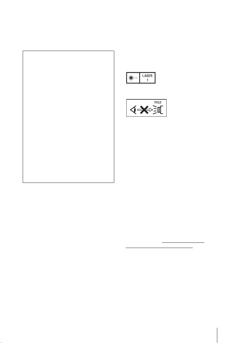
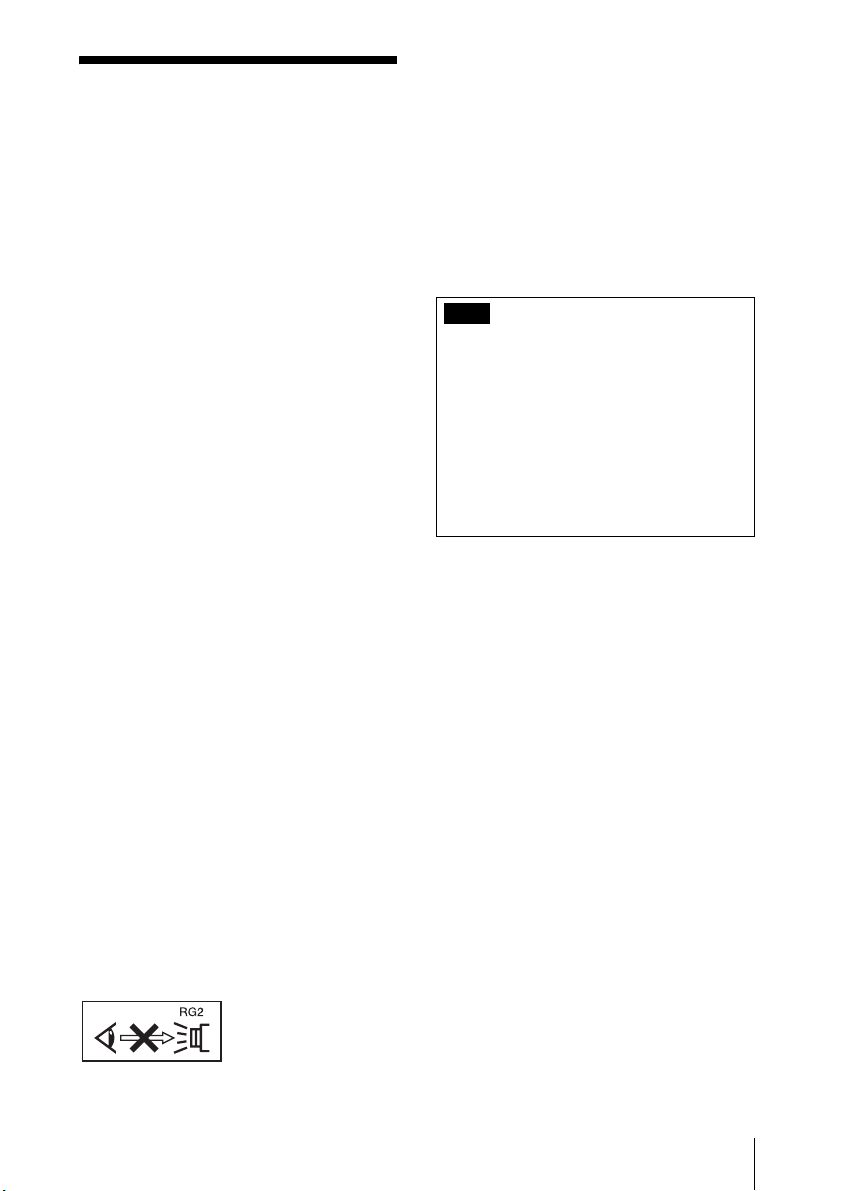
IEC 60825-1:2014
CLASS 1 LASER
PRODUCT
As with any bright
light source, do not
stare into the
beam, RG2 IEC
62471-5: 2015.
WARNING: Do not look into the lens
while in use.
Caution
Use of controls or adjustments or
performance of procedures other than
those specified herein may result in
hazardous radiation exposure.
Caution
The use of optical instruments with
this product will increase eye hazard.
For the customers in Europe
This apparatus shall not be used in the
residential area.
For the customers in the U.S.A.
CAUTION
Use of controls or adjustments or
performance of procedures other than
those specified herein may result in
hazardous radiation exposure.
This product is classified as a CLASS 3R
LASER PRODUCT.
WARNING
LASER RADIATION
AVOID DIRECT EYE EXPOSURE
CLASS 3R LASER PRODUCT
CAUTION
Do not look into the lens while in use.
For kundene i Norge
Dette utstyret kan kobles til et ITstrømfordelingssystem.
For the State of California, USA only
Perchlorate Material - special handling
may apply, See www.dtsc.ca.gov/
hazardouswaste/perchlorate
WARNING
3
Page 4

For the customers in the U.S.A.
SONY LIMITED WARRANTY
visit http://www.sony.com/psa/
warranty for important information
and complete terms and conditions
of Sony’s limited warranty
applicable to this product.
For the customers in Canada
SONY LIMITED WARRANTY
visit http://www.sonybiz.ca/pro/
lang/en/ca/article/resourceswarranty for important information
and complete terms and conditions
of Sony’s limited warranty
applicable to this product.
For the customers in Europe
Sony Professional Solutions Europe Standard Warranty and Exceptions
on Standard Warranty.
Please visit
http://www.pro.sony.eu/warranty
for important information and
complete terms and conditions.
For the customers in Korea
SONY LIMITED WARRANTY
visit http://bpeng.sony.co.kr/
handler/BPAS-Start for important
information and complete terms
and conditions of Sony’s limited
warranty applicable to this product.
- Please
- Please
- Please
4
WARNING
Page 5
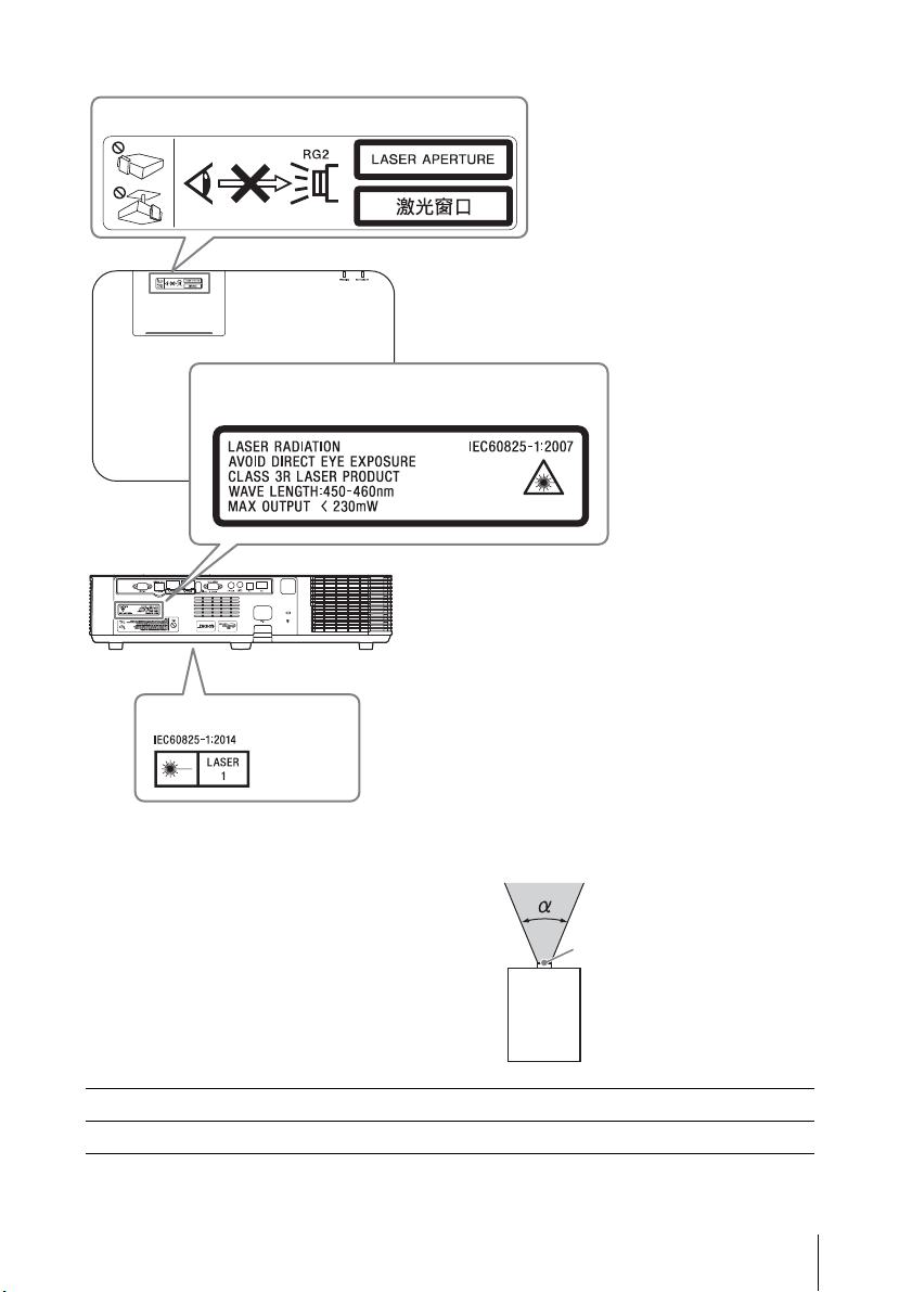
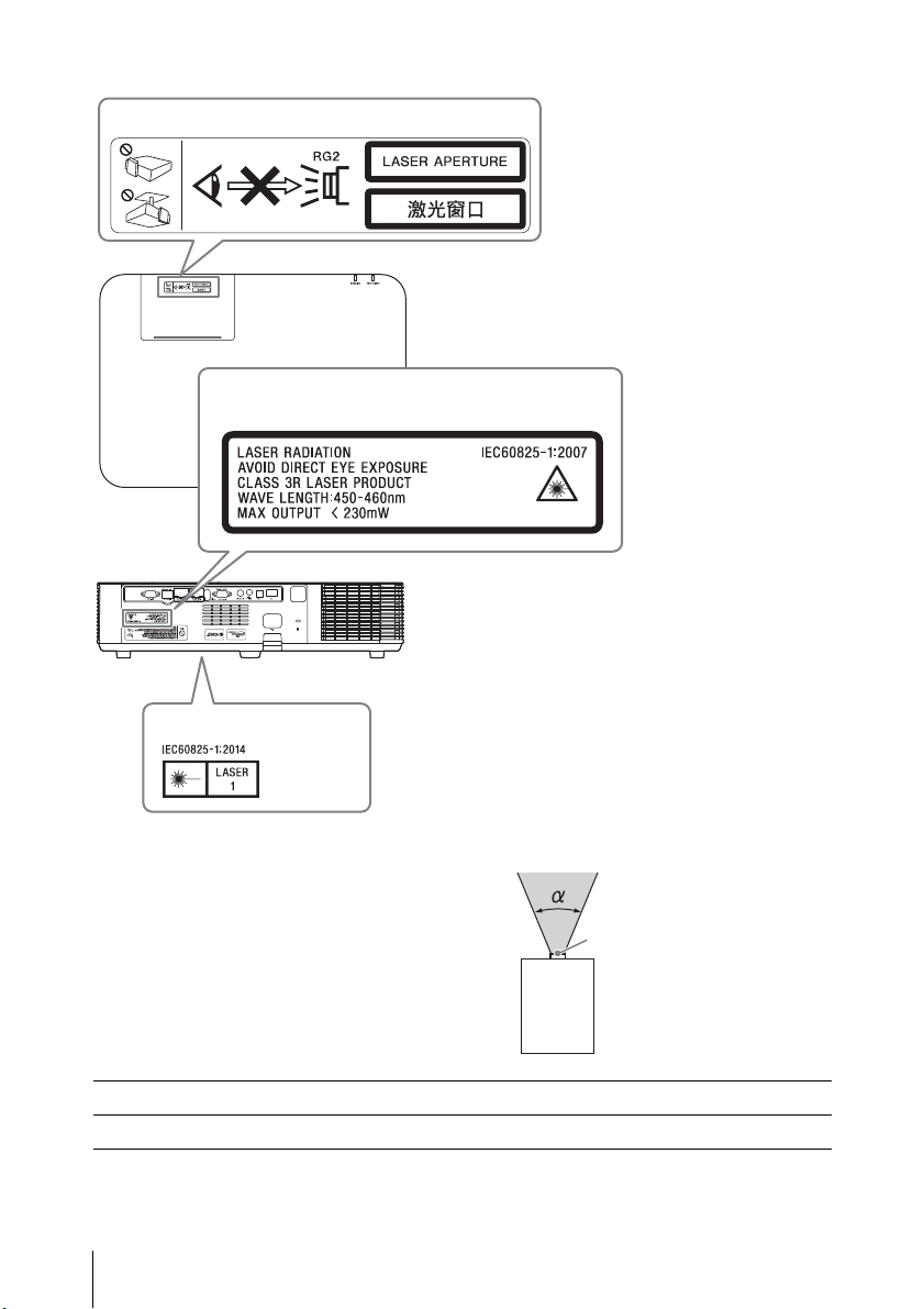
Location information of the labels
Laser Aperture
CLASS 1 label
CLASS 3R LABEL SY
Laser emission port
Light source specifications
4.5 W laser diodes
*1
21 pcs
*2
20 pcs
Beam divergence angle from lens of
this unit
Wavelength: 450 - 460 nm
*1: VPL-PHZ11
*2: VPL-PWZ11
Model Name Zoom maximum: α Zoom minimum: α
VPL-PHZ11/PWZ11 42° 30°
WARNING
5
Page 6
For the customers in Taiwan only
6
WARNING
Page 7
警告
注意
若要避免起火或電擊危險,請勿將本機
器曝露在雨中或潮濕環境中。
為避免觸電,切勿擅自打開機殼檢修,
必須找合格人員為您服務。
警告
此設備必須接地線。
注意事項
如果更換的電池不正確,會有爆炸的危
險。
僅使用製造商建議的同一種或相當類型
的電池進行更換。
當您棄置電池時,必須遵循當地或所在
國家的法律規定。
安裝電池
隨附一顆用於 RM-PJ8 遙控器的鋰電池
(CR2025)。為避免爆炸風險,請使用鋰
電池 (CR2025)。
警告
當安裝本裝置時,請在固定線路中配置
一個可方便使用的斷電裝置,或將電源
插頭連接至靠近裝置且可方便使用的電
源插座。如果在裝置運作期間發生故
障,請操作斷電裝置以便將電源關閉,
或拔下電源插頭。
警告
使用時請勿直視鏡頭。
注意
若不遵從這裡指定的方式使用控制元
件、進行調整或執行程序,可能會導致
危險的輻射外洩。
注意
使用本產品中的光學儀器將增加對眼睛
的傷害。
• 在使用前請始終確認本機運行正常。
無論保修期內外或基於任何理由,
SONY 對任何損壞概不負責。由於本
機故障造成的現有損失或預期利潤損
失,不作 (包括但不限於)賠償或
賠償。
• SONY 不對本機使用者或第三方提出的
索賠要求負起任何責任。
• SONY 不對因環境因素而中止或停止本
機相關服務,負起任何責任。
警告
1.使用符合各國適行安全法規的核准電
源線 (3 接腳)/ 設備接頭 / 具接地
接頭的插頭。
2.使用符合正確電壓 (電壓、安培)的
電源線 (3 接腳)/ 設備接頭 / 插
頭。
如果您對使用上述電源線 / 設備接頭 /
插頭有任何問題,請洽詢合格的維修人
員。
重要
標示牌位於底部。
與任何明亮的光源
一樣,請勿直視光
束,RG2 IEC
62471-5:2015。
警告
7
Page 8
標籤的位置資訊
雷射光圈
1類標籤
CLASS 3R 標籤
雷射發射埠
光源規格
來自本機鏡頭的光束發散角
4.5 W 雷射二極體
*1
21 個
*2
20 個
波長 : 450 - 460 nm
*1: VPL-PHZ1
*2: VPL-PWZ11
型號 縮放最大:α 縮放最小:α
VPL-PHZ11/PWZ1 42° 30°
8
警告
Page 9
注意事項
關於安全
• 確定本機的操作電壓與您當地的供電
電壓相同。如果需要電壓轉換,請洽
詢合格的 Sony 人員。
• 若有任何液體或固體滲入或掉入機殼
中,請拔下本機插頭,並請合格人員
檢查,然後才可繼續使用。
• 如果打算幾天不使用本機,請將本機
的插頭從牆上插座拔下。
• 若要拔掉電源線,請抓住插頭拔出。
切勿拉扯電源線本身。
• 牆上插座必須靠近本機並易於插拔。
• 只要本機的電源線仍連接在牆壁電源
插座上,即使本機的電源已經關閉,
但本機仍然未與交流電源斷開連接。
• 投影燈開啟時請勿直視鏡頭。
• 請勿將手或物體置於通風孔附近。排
氣溫度高。
• 在調整本機高度時,請小心不要使前
腳座夾到手指。在前腳座伸出時,請
勿用力壓本機頂端。
• 避免使用具有低電壓限制的延長線,
因為可能導致短路和人身傷害。
• 移動安裝在地板上的投影機時,請不
要使手指夾在本機和地面之間。
• 請勿在裝有機殼且蓋子打開的情況下
攜帶投影機。
• 請勿將本機安裝於靠近熱源的地方,
例如散熱器或空氣導管附近,或置於
直接日射、多麈、高濕度、易受機械
振動或衝擊的地方。
• 切勿自行將投影機安裝在天花板上或
搬運投影機。務必洽詢合格的 Sony 人
員 (需付費)。
• 如果通風孔阻塞,會累積內部熱量,
可能導致火災或本機損壞。為了確保
足夠的空氣流通和防止內部熱量累積,
請遵循以下項目:
• 在本機周圍留出空間 (第 10 頁)。
• 避免使用東西遮蓋通風孔 (排氣 / 進
氣)。
• 請勿將本機放置在原包裝紙、軟布、
紙張、地毯或紙屑等表面上。通風孔
可能會吸入這類材料。
• 請勿在鏡頭前放置任何可能在投影過
程中阻擋燈光的物體。來自燈光的熱
量可能會損壞物體。使用圖像靜音功
能切斷圖像。
• 運輸或安裝本機時,請勿使用防盜安
全條。如果您透過安全條抬起本機或
透過此安全條懸掛本機,可能會導致
本機掉落和損壞,並可能導致人身傷
害。
注意事項
9
Page 10
對於經銷商
超過
50 cm
超過
50 cm
超過 50 cm
15°
15°
• 牢牢安裝到天花板時,務必牢牢固定
機殼蓋。
將本機安裝在天花板上的安全注
意事項
• 切勿自行將投影機安裝在天花板上或
搬運投影機。務必洽詢合格的 Sony 人
員 (需付費)。
• 將本機安裝在天花板上時,務必使用
安全鋼索線等以防止本機掉落。請將
安裝工作委託給有經驗的承包商或安
裝人員。
關於安裝
• 避免將本機安裝在會遭受空調機直接
冷風或暖風吹到的位置。安裝於這種
位置可能會因為濕氣凝結或溫度上升
而導致本機故障。
• 避免將本機安裝在靠近熱量或煙霧偵
測器的位置。安裝於這種位置可能會
導致偵測器故障。
• 安裝本機時,請在本機與任何牆壁等
之間留出空間,如圖所示。
• 請避免以超過 15 度的水平傾斜角度來
使用本機。
• 將投影機安裝在地板或天花板上。安
裝在其他任何位置會造成色彩不一致
等故障或縮短投影燈壽命。
• 避免在溫度或濕度非常高或溫度非常
低的地方使用本機。
• 避免將本機安裝在多塵或多煙的環境。
否則濾網會受到阻塞,可能會導致本
機故障或損壞。
• 在海拔 1500 公尺或以上使用本機時,
將安裝設置選單中的 “ 高海拔高度模
式 ” 設定為 “ 開 ”。在高地使用本
機時,若未設定此模式,可能會造成
不良影響,例如降低某些元件的可靠
性。
清潔鏡頭和機殼時
• 清潔之前,務必將 AC 電源線從 AC 電源
插座拔下。
• 如果使用髒污的布擦拭本機,可能會
使機殼刮傷。
• 如果本機暴露在殺蟲劑等揮發性物質
中,或是本機長時間接觸到橡膠或乙
烯樹脂製品,本機可能會劣化,或是
塗層可能剝落。
• 請勿以手直接觸碰鏡頭。
10
注意事項
Page 11

• 清潔鏡頭表面時:
請使用軟布,例如玻璃清潔布,輕輕
擦拭鏡頭。若要除去頑強污點,請使
用沾水的微濕軟布。切勿使用酒精、
苯或稀釋劑等溶劑,或是酸性、鹼性
或剝蝕性清潔劑,或化學清潔布。
• 清潔機殼時:
使用軟布輕輕擦拭機殼。若要除去頑
強污點,請使用軟布沾上微量的中性
清潔液,擰乾後擦拭,然後再使用乾
的軟布擦拭。切勿使用酒精、苯或稀
釋劑等溶劑,或是酸性、鹼性或剝蝕
性清潔劑,或化學清潔布。
關於照明
• 投影燈壽命根據各個投影燈的個別差
異或使用條件而異。因此,即使尚未
到達指定的更換時間,投影燈也可能
會破裂或不亮。
• 經過更換時間後,可能會破裂。如果
投影圖像上顯示訊息,請盡快更換新
的投影燈,即使投影燈正常亮起。
關於攜帶
本機為精密設備。攜帶本機時,請勿使
本機受到衝擊或掉落。這樣可能會使本
機受損。
攜帶本機時,請以雙手緊握其防滑表
面,以免掉落。
要獲得最佳畫質,請不要讓螢幕前方暴
露在直接燈光或陽光照射下。
關於散熱
投影機機殼的溫度可能在使用期間或使
用後立即升高;然而,這並非故障。
關於螢幕
使用表面不平整的螢幕時,視螢幕和本
機之間的距離或縮放倍數而定,螢幕上
偶爾可能會出現條紋圖案。這並非本機
故障。
關於風扇
由於投影機內部裝有風扇,以防止內部
溫度升高,因此可能會有一些噪音。這
是製造過程的正常結果,並不是故障。
但是,如果發出異常噪音,請洽詢合格
的 Sony 人員。
關於投影燈
用作光源的投影燈使用具有高內部壓力
的水銀。高壓水銀燈具有以下特性:
• 投影燈的亮度會隨使用時間而降低。
• 由於時間流逝導致的衝擊、損壞或劣
化,投影燈可能會破裂並發出很大的
噪音。投影燈可能變得不亮,而且可
能會燒毀。
關於 LCD 投影機
LCD 投影機採用高精度技術製造。不過,
您可能會發現細小的黑點和 / 或亮點
(紅色、藍色或綠色)一直出現在 LCD
投影機上。這是製造過程的正常結果,
並不是故障。
此外,當您使用多個 LCD 投影機投射到
螢幕上時,即使其型號相同,這些投影
機之間的色彩重現可能不同,因為每台
投影機的色彩平衡設定可能不同。
關於凝結
如果安裝投影機的地方室內溫度快速改
變,或是將投影機從寒冷的地方突然移
至溫暖的地方,投影機內可能會產生凝
結。由於凝結可能造成故障,因此請小
心調整空調機的溫度設定。如果產生凝
結,讓投影機電源打開擱置約兩小時後
再使用。
注意事項
11
Page 12

Table of Contents
Precautions ................................ 14
On safety ............................... 14
Safety precautions for installing
the unit on a ceiling ............ 15
On Installation ...................... 16
On cleaning the projection
window and the cabinet .... 16
On Illumination ..................... 17
On Heat Dissipation .............. 17
On Screen ............................. 17
On Fan ................................... 17
On inspection of light source
related parts ....................... 17
On disposing used
products .............................. 17
On LCD Projector .................. 17
On condensation .................. 17
Notes on security .................. 18
Checking the Supplied
Accessories ......................... 19
Installing batteries ................ 19
Overview
Location and Function of
Controls ....................................20
Main Unit ..............................20
Terminals .............................. 21
Remote Commander and
Control Panel Keys ..............22
Preparation
Connecting the Projector ..........25
Connecting a Computer .......25
Connecting a Video
equipment ..........................28
Connecting a HDBaseT™
equipment ..........................29
Connecting Audio
Equipment .......................... 32
Projecting/Adjusting an Image
Projecting an Image .................. 33
Adjusting the Focus, Size, and
Position of the Projected
Image ..................................34
Turning Off the Power ..........39
Adjustments and Settings Using
a Menu
Using a MENU ........................... 40
The Picture Menu ......................42
The Screen Menu .......................44
The Function Menu ....................47
The Operation Menu .................49
The Connection/Power Menu ...50
The Installation Menu ................54
The Information Menu ..............56
Network
Using Network Features ............ 57
Displaying the Control Window
of the Projector with a Web
Browser ...............................58
Confirming the Information
regarding the Projector ...... 59
Operating the Projector from a
Computer ............................ 59
Using the e-mail report
Function ..............................59
12
Table of Contents
Page 13

Setting the LAN Network of the
projector ............................. 61
Setting the WLAN Network of
the projector ....................... 61
Setting the Custom Labels for
the Input Terminals of the
Projector ............................ 64
Setting the Control Protocol of
the Projector .......................65
Presentation Function via Network
Using Presentation Function via
Network ...................................70
Installing Projector Station for
Network Presentation ......... 71
Starting Projector Station for
Network Presentation ......... 71
Projecting an Image ............. 71
Connection Settings ............. 73
Using the Controller .............. 73
One-Click projecting
function ............................... 74
Option format ....................... 75
Use Projector Station for
Network Presentation without
installing it to the
computer. ........................... 76
Error code list of Projector
Station for Projector Station
for Network Presentation ... 78
Others
Indicators ...................................82
Messages List ............................84
Troubleshooting ........................86
Cleaning the Air Filter ................89
Specifications ............................ 91
Projection Distance and Lens Shift
Range ....................................... 97
Dimensions ..............................100
About Trademarks ................... 102
END USER LICENSE
AGREEMENT ........................... 103
Index .........................................119
Playing Video and Audio using
USB Connection
Playing Video and Audio using USB
Connection ............................. 80
Starting USB Display ............ 80
Playing Video and Audio ...... 81
Using the Controller .............. 81
Tab l e of Co n ten ts
13
Page 14
Precautions
On safety
• Check that the operating voltage of
your unit is identical with the voltage
of your local power supply. If voltage
adaptation is required, consult with
qualified Sony personnel.
• Should any liquid or solid object fall
into the cabinet, unplug the unit and
have it checked by qualified Sony
personnel before operating it further.
• Unplug the unit from the wall outlet
if it is not to be used for several days.
• To disconnect the cord, pull it out by
the plug. Never pull the cord itself.
• The wall outlet should be near the
unit and easily accessible.
• The unit is not disconnected from the
AC power source (mains) as long as it
is connected to the wall outlet, even
if the unit itself has been turned off.
• Do not look into the lens while in use.
• When turning on the projector, make
sure no one is peeking at the
projection lens.
• Do not let children use the unit alone.
• Do not place your hand or objects
near the ventilation holes — the air
coming out is hot.
• Be careful not to catch your fingers
by the feet (adjustable) when you
adjust the height of the unit. Do not
push hard on the top of the unit with
the adjuster out.
• Be sure to use two people to grasp
both sides of the unit when carrying
the unit.
• Avoid using an extension cord with a
low voltage limited since it may
cause the short-circuit and physical
incidents.
• Do not catch your finger between the
unit and surface of the floor when
moving the projector installed on the
floor.
• Be careful not to catch your finger in
the cooling fan.
• Do not carry the projector with the
cabinet on and with its cover open.
• Do not install the unit in a location
near heat sources such as radiators
or air ducts, or in a place subject to
direct sunlight, excessive dust or
humidity, mechanical vibration or
shock.
• If a user disassembles, repairs, or
alters the unit, it may cause a serious
problem to the user’s safety.
• If the projector malfunctions or is
damaged, consult with a qualified
Sony personnel.
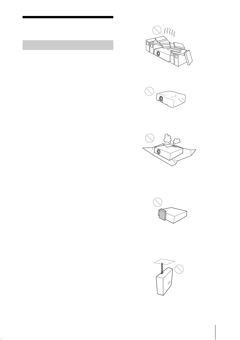
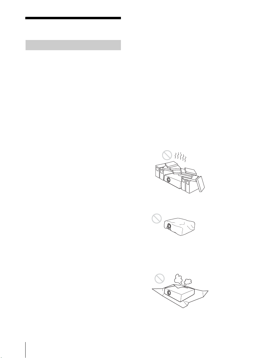
• If the ventilation holes are blocked,
internal heat builds up, and it may
cause a fire or damage the unit. To
allow adequate air circulation and
prevent internal heat build-up,
follow the items below:
• Place the unit, leaving sufficient
space from walls or any objects
(page 16).
• Avoid using something to cover the
ventilation holes (exhaust/intake).
• Do not place the unit on surfaces
such as an original packing sheet,
soft cloth, papers, rugs, or scraps of
paper. The ventilation holes may
take in such materials.
14
Precautions
Page 15
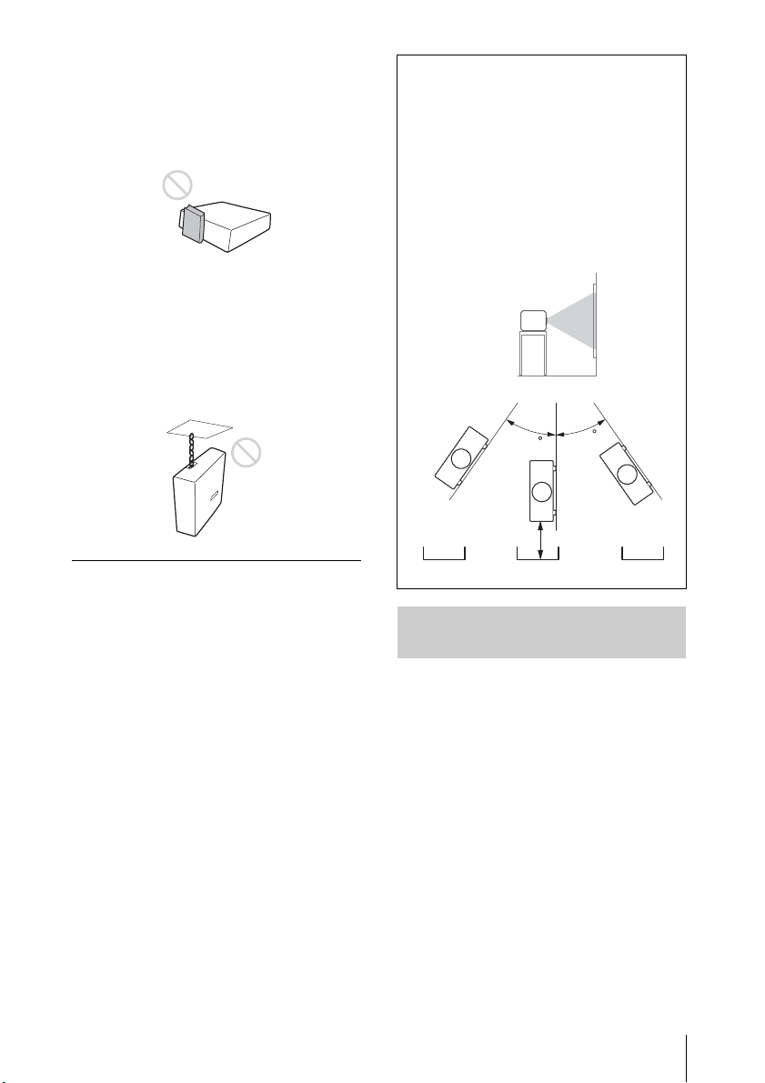
• Do not place any object just in front
Portrait (The buttons of
the unit face down)
From 50 cm
(19
11
/16") to
70 cm (27
9
/16")
Metal tray
of the lens that may block the light
during projection. Heat from the light
may damage the object. Use the
picture muting function to cut off the
picture.
• Do not use the Security bar for the
purpose of preventing theft for
transporting or installing the unit. If
you lift the unit by the Security bar or
hang the unit by this bar, it may
cause the unit to fall and be
damaged, and may result in personal
injury.
Caution
When installing the unit at the angle
illustrated, if the ventilation holes are
facing down, install a metal tray
(min. 40 cm × 40 cm (15
3
/4" ×
15 3/4")) at the distance indicated
below directly under the ventilation
holes.
Ensure that foreign materials or
liquids do not drop into the
ventilation holes.
For dealers
• When the projector is mounted on
the ceiling, a Sony bracket or
recommended equivalent must be
used for installation.
• Be sure to secure the cabinet cover
firmly when installing to the ceiling
firmly.
65
65
Safety precautions for installing the unit on a ceiling
• Never mount the projector on the
ceiling or move it by yourself. Be sure
to consult the store where you
purchased the projector or a
dedicated installer.
• When installing the unit on a ceiling,
be sure to use a safety wire, etc., to
prevent the unit from falling. For the
installation, be sure to consult the
store where you purchased the
projector or a dedicated installer.
Precautions
15
Page 16
On Installation
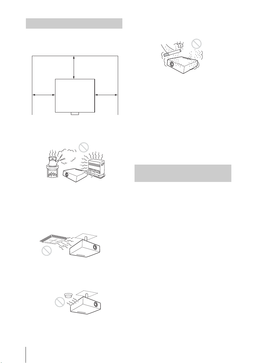
More than
50 cm
(19
11
/16")
More than
50 cm
(19
11
/16")
More than 50 cm (19
11
/16")
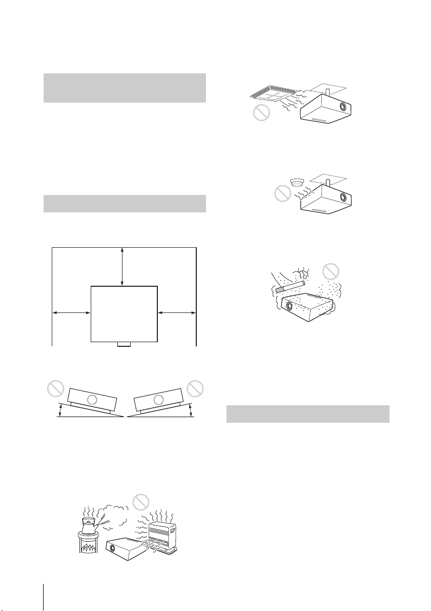
• When installing the unit, leave space
between any walls, etc. and the unit
as illustrated.
• Avoid using the unit in a location
where the temperature or humidity is
very high, or temperature is very low.
will become obstructed, and this
may cause a malfunction of the unit
or damage it.
• When using the unit at an altitude of
1,500 m or higher, set “High Altitude
Mode” to “On” in the Installation
menu. Failing to set this mode when
using the unit at high altitudes could
have adverse effects, such as
reducing the reliability of certain
components.
• Set “Installation Attitude” on the
Installation menu correctly to suit to
the Installation angle. Continuing to
use the wrong setting may affect
component reliability.
On cleaning the projection window and the cabinet
• Avoid installing the unit in a location
subject to direct cool or warm air
from an air-conditioner. Installing in
such a location may cause
malfunction of the unit due to
moisture condensation or rise in
temperature.
• Avoid installing the unit in a location
near a heat or smoke sensor.
Installing in such a location may
cause malfunction of the sensor.
• Avoid installing the unit in a very
16
dusty or extremely smoky
environment. Otherwise, the air filter
Precautions
• Be sure to disconnect the AC power
cord from the AC outlet before
cleaning.
• If you rub on the unit with a stained
cloth, the cabinet may be scratched.
• If the unit is exposed to volatile
materials such as insecticide, or the
unit is in contact with a rubber or
vinyl resin product for a long period
of time, the unit may deteriorate or
the coating may come off.
• Do not touch the projection window
with bare hands.
• On cleaning the projection window
surface:
Wipe the projection window gentlywith a soft cloth, such as a glass
cleaning cloth. Stubborn stains may
be removed with a soft cloth lightly
dampened with water. Never use
solvent such as alcohol, benzene or
thinner, or acid, alkaline or abrasive
detergent, or a chemical cleaning
cloth.
Page 17

• On cleaning the cabinet:
Clean the cabinet gently with a soft
cloth. Stubborn stains may be
removed with a soft cloth lightly
dampened with mild detergent
solution and wrung, followed by
wiping with a soft dry cloth. Never
use solvent such as alcohol, benzene
or thinner, or acid, alkaline or
abrasive detergent, or a chemical
cleaning cloth.
On Illumination
To obtain the best picture, the front of
the screen should not be exposed to
direct lighting or sunlight.
On Heat Dissipation
On inspection of light source related parts
Since the unit uses a laser, when
performing maintenance or inspection
of light source related parts, particular
attention and a safe environment are
necessary. Be sure to consult with
qualified Sony personnel.
On disposing used products
Do not dispose the used products and
general garbage together.
Correctly dispose of used products to
avoid harming the environment or the
health of yourself and others. Follow
the disposal regulations of your area.
The temperature of the projector
cabinet may increase during or
immediately after use; however, this is
not a malfunction.
On Screen
When using a screen with an uneven
surface, stripes pattern may rarely
appear on the screen depending on
the distance between the screen and
the unit or the zooming
magnifications. This is not a
malfunction of the unit.
On Fan
Since the projector is equipped with a
fan inside to prevent internal
temperature from rising, there may be
some noise. This is a normal result of
the manufacturing process and does
not indicate a malfunction. If, however,
in a case of abnormal noise, consult
with qualified Sony personnel.
On LCD Projector
The LCD projector is manufactured
using high-precision technology. You
may, however, see tiny black points
and/or bright points (red, blue, or
green) that continuously appear on
the LCD projector. This is a normal
result of the manufacturing process
and does not indicate a malfunction.
Also, when you use multiple LCD
projectors to project onto a screen,
even if they are of the same model, the
color reproduction among projectors
may vary, since color balance may be
set differently from one projector to
the next.
On condensation
If the room temperature where the
projector is installed changes rapidly,
or if the projector is moved suddenly
from a cold to a warm place,
condensation in the projector may
occur. As the condensation may cause
malfunction, be careful in adjusting
temperature settings of the air
conditioner. If condensation occurs,
leave the projector turned on for about
two hours before use.
Precautions
17
Page 18

Notes on security
• SONY WILL NOT BE LIABLE FOR
DAMAGES OF ANY KIND RESULTING
FROM A FAILURE TO IMPLEMENT
PROPER SECURITY MEASURES ON
TRANSMISSION DEVICES,
UNAVOIDABLE DATA LEAKS
RESULTING FROM TRANSMISSION
SPECIFICATIONS, OR SECURITY
PROBLEMS OF ANY KIND.
• Depending on the operating
environment, unauthorized third
parties on the network may be able
to access the unit. When connecting
the unit to the network, be sure to
confirm that the network is protected
securely.
• Communication content may be
unknowingly intercepted by
unauthorized third parties in the
vicinity of the signals. When using
wireless LAN communication,
implement security measures
properly to protect the
communication content.
• From a safety standpoint, when
using the unit connected with the
network, it is strongly recommended
to access the Control window via a
Web browser and change the access
limitation settings from the factory
preset values (refer to “Using
Network Features” in the Operating
Instructions).
Changing the password regularly is
also recommended.
• Do not browse any other website in
the Web browser while making
settings or after making settings.
Since the login status remains in the
Web browser, close the Web browser
when you complete the settings to
prevent unauthorized third parties
from using the unit or harmful
programs from running.
Notes
• Always verify that the unit is
operating properly before use.
SONY WILL NOT BE LIABLE FOR
DAMAGES OF ANY KIND
INCLUDING, BUT NOT LIMITED TO,
COMPENSATION OR
REIMBURSEMENT ON ACCOUNT OF
THE LOSS OF PRESENT OR
PROSPECTIVE PROFITS DUE TO
FAILURE OF THIS UNIT, EITHER
DURING THE WARRANTY PERIOD
OR AFTER EXPIRATION OF THE
WARRANTY, OR FOR ANY OTHER
REASON WHATSOEVER.
• SONY WILL NOT BE LIABLE FOR
CLAIMS OF ANY KIND MADE BY
USERS OF THIS UNIT OR MADE BY
THIRD PARTIES.
• SONY WILL NOT BE LIABLE FOR THE
TERMINATION OR
DISCONTINUATION OF ANY
SERVICES RELATED TO THIS UNIT
THAT MAY RESULT DUE TO
CIRCUMSTANCES OF ANY KIND.
18
Precautions
Page 19
Checking the Supplied
With the
(plus) side facing
up.
Accessories
RM-PJ8 Remote Commander (1)
Lithium battery (CR2025) (1)
The battery is already installed.
Before using the remote
commander, remove the insulation
film.
AC power cord (1)
Operating Instructions (this manual) (1)
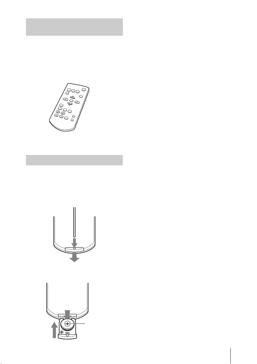
Installing batteries
1 Pull out the lithium battery
compartment.
Pull out the battery compartment
with a stick as shown in the
illustration.
3 Close the lithium battery
compartment.
2 Insert a lithium battery.
Precautions
19
Page 20
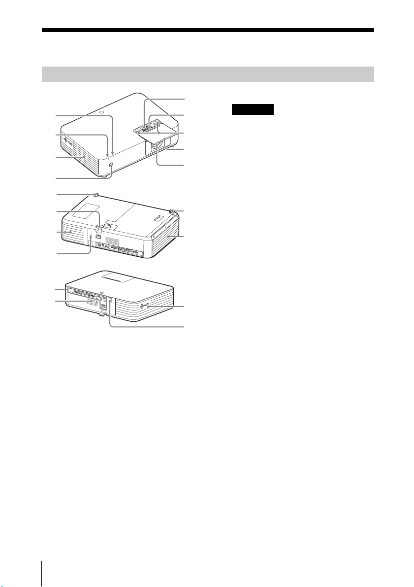
Overview
Caution
Location and Function of Controls
Main Unit
9
8
7
6
Zoom lever (page 34)
Focus lever (page 34)
Lens shift dial (page 34)
Lens Adjustment Cover
(page 35)
Slide open to adjust lens shift.
Projection lens
Remote control Receiver
1
2
3
4
5
Ventilation holes (exhaust)
Do not place anything near the
ventilation holes as this may cause
internal heat buildup. Do not place
your hand or deformable items
(plastic, etc.) near the ventilation
holes or around the projector, as it
may cause damage or personal
injury.
ON/STANDBY indicator
(page 82)
WARNING indicator (page 82)
Front feet (adjustable) (page 35)
Side cover/Ventilation holes
(intake) (page 89)
Security lock
Connects to an optional security
cable manufactured by
Kensington.
For details, visit Kensington’s web
site.
http://www.kensington.com/
Ventilation holes (intake)
(page 89)
Security bar
Connects to a commercially
available security chain or wire.
Control panel (page 22)
20
Location and Function of Controls
Speaker
Terminals (page 21)
Page 21
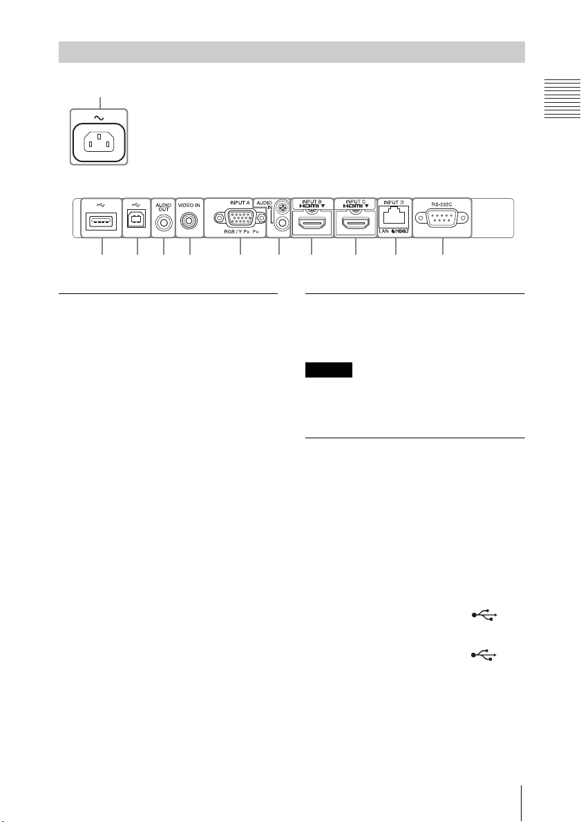
Overview
Note
Terminals
Input (pages 25, 28)
INPUT A
Video: RGB/YPBPR input terminal
(RGB/YP
INPUT B
Video: HDMI input terminal (HDMI)
Audio: HDMI input terminal (HDMI)
INPUT C
Video: HDMI input terminal (HDMI)
Audio: HDMI input terminal (HDMI)
INPUT D
HDBaseT terminal/LAN terminal
(page 58)
Use a straight CAT5e or CAT6
shielded LAN cable (not supplied).
AUDIO (AUDIO IN)
Audio: Audio input terminal
VIDEO (VIDEO IN)
Video: Video input terminal
Output (page 32)
AUDIO (AUDIO OUT)
Audio: Audio output terminal
BPR)
When the speaker setting is set to
“Always On” and the light is turned off,
INPUT A is enabled.
Others
RS-232C terminal (RS-232C)
RS-232C compatible control
terminal. Connects the computer’s
RS-232C terminal and the RS-232C
cross cables.
AC IN (~) socket
Connects the supplied AC power
cord.
USB terminal (Type A) ( )
(page 27)
USB terminal (Type B) ( )
(page 80)
Location and Function of Controls
21
Page 22
Note
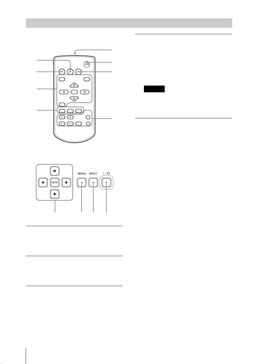
Remote Commander and Control Panel Keys
2
3
4
5
6
1
4
7
INPUT
MENU
APA ECO MODE
RETURN
ASPECT
D ZOOM
KEYSTONE
ENTER
VOLUME
PATTERN
FREEZE
BLANK
MUTING
RESET
Remote Commander
Control Panel Keys
Turning on the power/Going to
standby mode
/ (On/Standby) key
Selecting an input signal
(page 33)
INPUT key
Operating a menu (page 40)
MENU key
RESET key
ENTER //// (arrow) keys
RETURN key
Adjusting the image (page 34)
ASPECT key (page 44)
KEYSTONE key (page 36)
PATTERN key (page 39)
APA (Auto Pixel Alignment) key
(page 39)
*1: Use this key when inputting a
computer signal via the RGB
input terminal (INPUT A).
Using various functions during
projecting
D ZOOM (Digital Zoom) +/– key
*1 *2
Enlarges a portion of the image
while projecting.
1
Press the D ZOOM + key to
display the digital zoom icon on
the projected image.
2
Press the /// keys to move
the digital zoom icon to the point
on the image you want to
enlarge.
3
Press the D ZOOM + key or the D
ZOOM – key repeatedly to
change the enlargement ratio.
The image can be enlarged up to
4 times.
Press the RESET key to restore the
previous image.
BLANK key
Cuts off the projected image
temporarily. Press again to restore
the previous image.
MUTING key
Mutes the audio output
temporarily. Press again to restore
the previous volume.
VOLUME +/– key
Adjusts the volume output.
*1
22
Location and Function of Controls
Page 23
Overview
Notes
Note
RETURN
ECO
User
ECO Mode
:Sel
:Back
FREEZE key
*2
Pauses a projected image. Press
again to restore the image.
*1: Use this key when inputting a
computer signal. But it may not
be used depending on the
resolution of the input signal.
*2: Use this key when inputting a
computer signal. You cannot use
this key when “Type B USB” or
“Network” is selected as the
input.
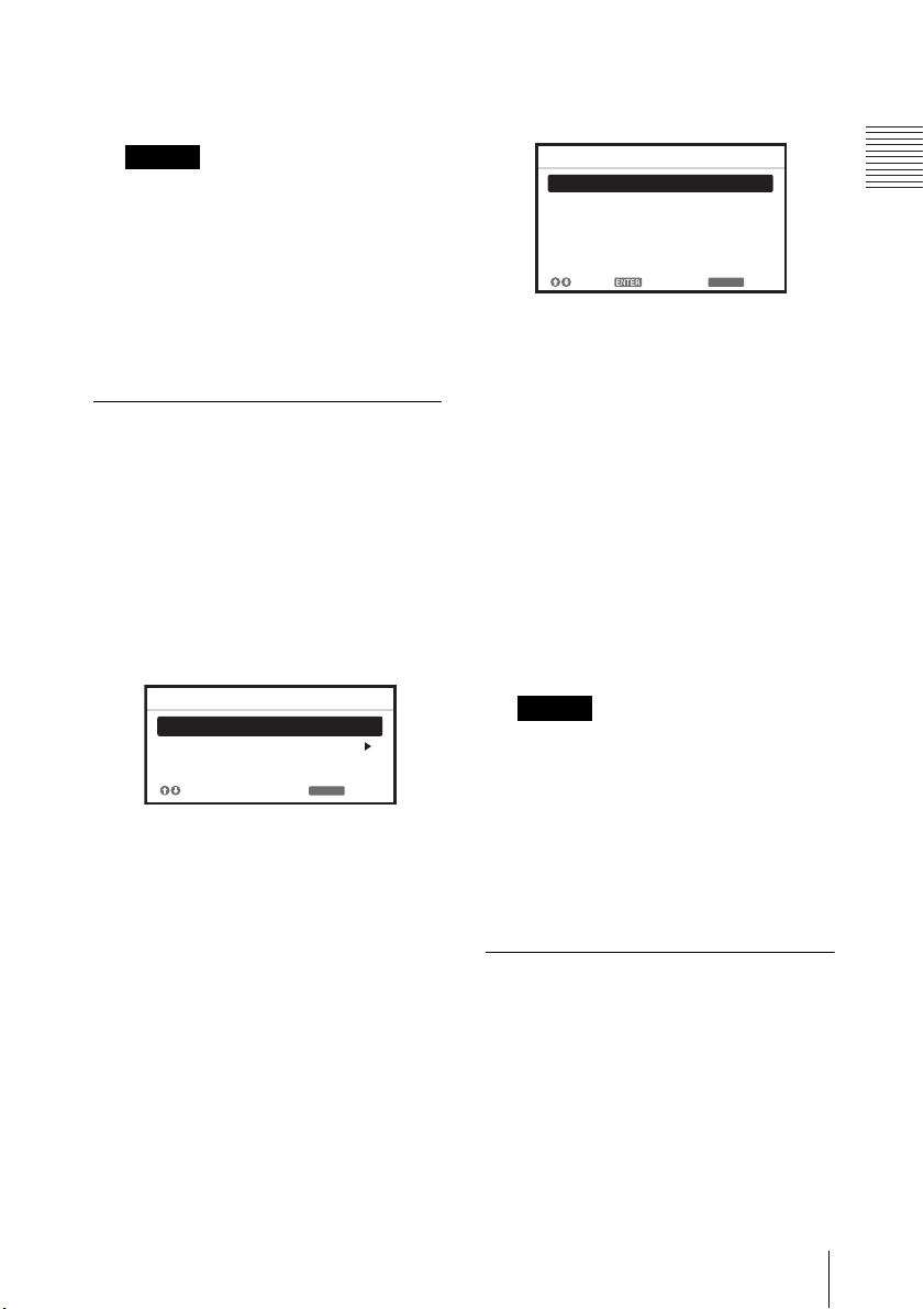
Setting the energy–saving
mode easily
ECO MODE key
Energy-saving mode can be set
easily. Energy-saving mode
consists of “Light Output Mode,”
“With No Input,” “With Static
Signal” and “Standby Mode.”
1
Press the ECO MODE key to
display the ECO Mode menu.
3
Select “User” then press the
key.
The setting items appear.
User
Light Output Mode Standard
Constant Brightness
Auto Power Saving
With No Input
With Static Signal
Standby Mode
:S el
4
Press the / key to select the
:S et
ON
Off
Light Dimming
Standard
RETURN
:Back
item then press the ENTER key.
5
Press the / key to select the
setting value.
6
Press the ENTER key.
The screen returns to the User
screen.
For details on each setting, see
“Speaker Setting” in the Function
menu (page 47), “Light Output
Mode,” “ Constant Brightness,”
“With No Input,” “With Static
Signal,” and “Standby Mode” in
the Connection/Power menu
(page 50).
2
Press the / key or ECO MODE
key to select “ECO” or “User”
mode.
ECO:
Sets each mode to the
optimum energy-saving value.
Light Output Mode: Low
With No Input: Standby
With Static Signal: Light
Dimming
Standby Mode: Low
Speaker Setting: Sync with
Power
User:
Sets each item of the ECO
Mode menu as you desire (go
to step 3).
If you set “ECO Mode” to “ECO,” or
“Standby Mode”(in “User”) to “Low,”
the network control function will be
disabled in standby mode. If the
external control is being performed
by using the network or network
control function, do not select “ECO,”
or do not set “Standby Mode” ( in
“User”) to “Low.”
Infrared transmitter
About remote commander
operation
• Direct the remote commander
toward the remote control receiver.
• The shorter the distance between
the remote commander and the
projector is, the wider the angle
within which the remote
Location and Function of Controls
23
Page 24

commander can control the
projector becomes.
• Make sure that nothing obstructs the
infrared beam between the remote
commander and the remote control
receiver on the projector.
24
Location and Function of Controls
Page 25
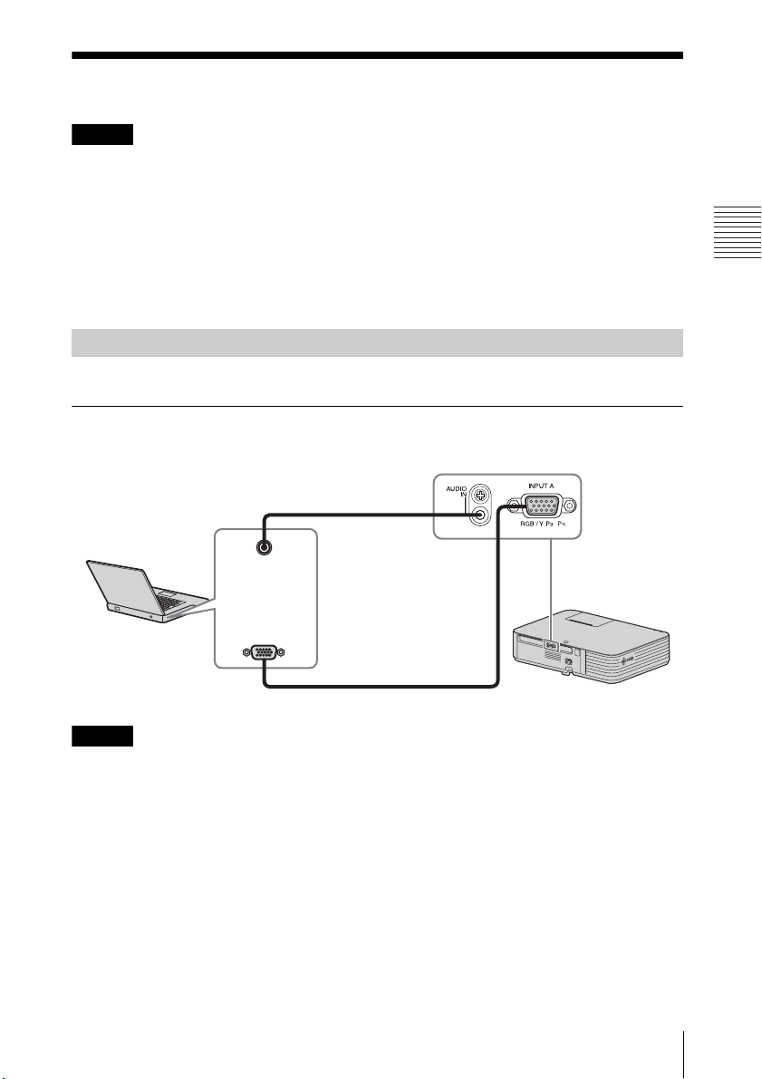
Preparation
Preparation
Notes
Note
RGB output
terminal
Audio output
terminal
Mini D-sub 15-pin cable (not supplied)
Computer
Audio cable (Stereo mini plug) (not supplied)
Connecting the Projector
• Make sure all the equipment is powered off when connecting the projector.
• Use the proper cables for each connection.
• Insert the cable plugs firmly. Loose connections may reduce performance of
picture signals or cause a malfunction. When pulling out a cable, be sure to grip
it by the plug, not the cable itself.
• For more information, refer also to the instruction manuals of the equipment you
are connecting.
• Use a no-resistance audio cable.
Connection with a computer is explained for each input signal.
INPUT A
For connecting a computer with an RGB output terminal.
In screen setting of your computer, it is recommended that you set the resolution
of an external monitor as below;
• VPL-PHZ11: 1,920 × 1,200 pixels
• VPL-PWZ11: 1,280 × 800 pixels
Connecting a Computer
Connecting the Projector
25
Page 26
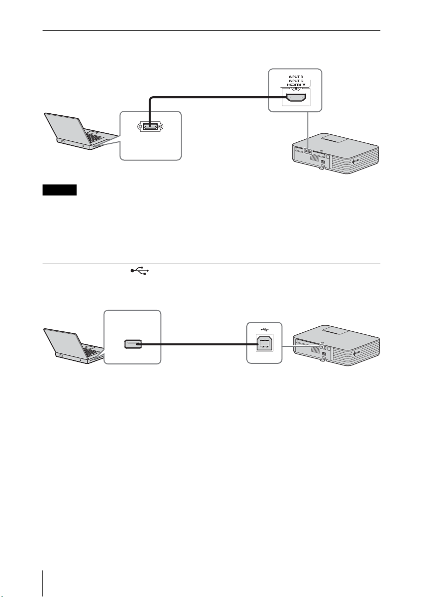
INPUT B/INPUT C
Notes
HDMI output
terminal
HDMI cable (not supplied)
Computer
USB A-B cable
(not supplied)
Computer
USB terminal
(Type A)
For connecting a computer with an HDMI output terminal.
• Use HDMI-compatible equipment which has the HDMI Logo.
• Use a high speed HDMI cable(s) on which the cable type logo is specified. (Sony
products are recommended.)
• The HDMI terminal of this projector is not compatible with DSD (Direct Stream
Digital) Signal or CEC (Consumer Electronics Control) Signal.
USB terminal (Type B) ( )
For connecting to a computer with a USB terminal (“Playing Video and Audio using
USB Connection” (page 80)).
26
Connecting the Projector
Page 27
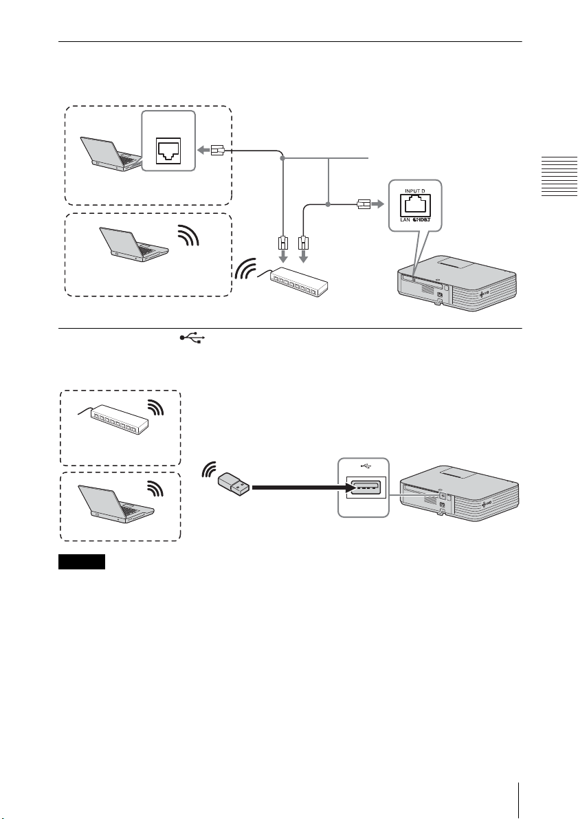
Preparation
LAN terminal
Notes
LAN cable (straight type)
(not supplied)
Computer
LAN
terminal
Wired connection
Computer
Wireless connection
USB wireless LAN module
IFU-WLM3 (not supplied)
Computer
Wireless router,
access point
For connecting to a computer via a hub or router (“Presentation Function via
Network” (page 70)).
USB terminal (Type A) ( )
For connecting a USB wireless LAN module IFU-WLM3 (not supplied) (“Presentation
Function via Network” (page 70)).
• Undesignated USB wireless LAN modules do not work.
• When connecting/disconnecting the USB wireless LAN module, make sure that
the projector is in Standby mode (Standby Mode: “Low”), or the AC power cord
is unplugged from the wall outlet.
• For connecting to the access point, access to the Web browser, and input the
settings for the access point to connect. For details, see “Setting the WLAN
Network of the projector” (page 61).
Connecting the Projector
27
Page 28
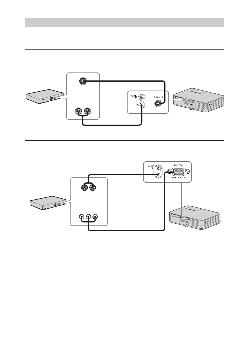
Connecting a Video equipment
Video cable (not supplied)
Audio cable (Phono plug × 2 – stereo mini plug) (not supplied)
Video output
terminal
Audio output
terminal
Video equipment
Component – Mini D-sub 15-pin cable (not supplied)
Audio cable (Phono plug × 2 –
stereo mini plug) (not supplied)
Video equipment
YP
BPR output
terminal
Audio output
terminal
Connections with a VHS video deck, DVD player, or BD player are explained for each
input signal.
VIDEO IN
For connecting video equipment with a video output terminal.
INPUT A
For connecting video equipment with a YPBPR output terminal.
28
Connecting the Projector
Page 29
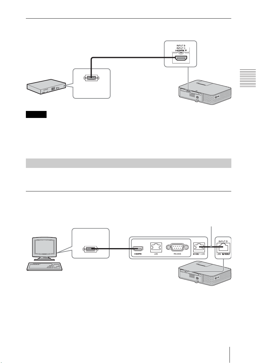
Preparation
INPUT B/INPUT C
Notes
Video equipment
HDMI cable (not supplied)
HDMI output
terminal
HDMI cable (not supplied)
HDMI output
terminal
Computer
HDBaseT transmitter
LAN cable: STP type (CAT5e or
higher, straight, not supplied)
For connecting video equipment with an HDMI output terminal.
• Use HDMI-compatible equipment which has the HDMI Logo.
• Use a high speed HDMI cable(s) on which the cable type logo is specified. (Sony
products are recommended.)
• The HDMI terminal of this projector is not compatible with DSD (Direct Stream
Digital) Signal or CEC (Consumer Electronics Control) Signal.
Connecting a HDBaseT™ equipment
For connecting the computer, video equipment, and network equipment via the
HDBaseT transmitter.
Connecting to the computer
INPUT D
Connecting the Projector
29
Page 30
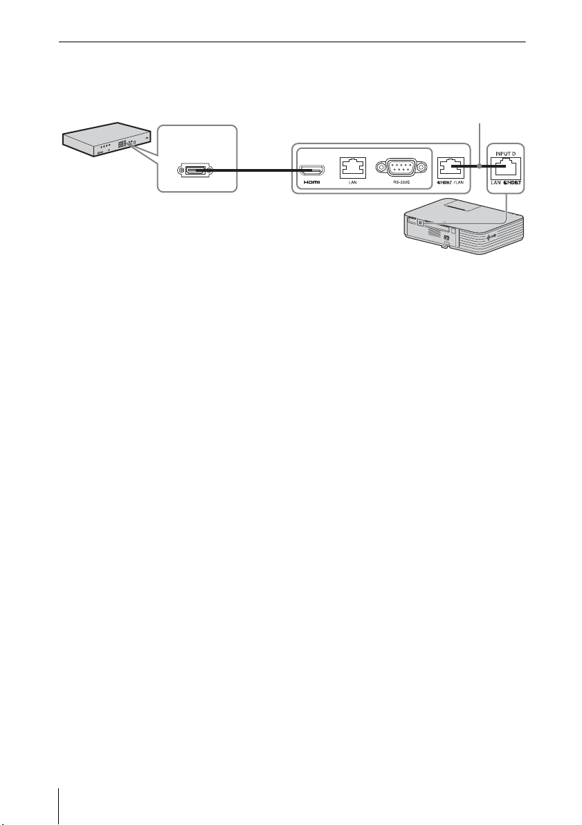
Connecting to the video equipment
HDMI cable (not supplied)
HDMI output
terminal
Video equipment
HDBaseT transmitter
LAN cable: STP type (CAT5e or
higher, straight, not supplied)
INPUT D
Notes for connecting this unit and the HDBaseT transmitter
• Ask a professional or Sony dealer to perform wiring. If wiring is not correct, the
transmission characteristics of the cable will not be achieved, and image or
sound may break up or you may experience unstable performance.
• Connect the cable directly to the HDBaseT transmitter without going through a
hub or router.
• Use cables that meet the following conditions.
- CAT5e or higher
- Shielded type (covering connectors)
- Straight wire connection
- Single wire
• When installing the cables, use a cable tester, cable analyzer, or similar device to
check if the cables meet the CAT5e or higher requirement. If there is a transit
connector between this unit and the HDBaseT transmitter, include it when
measuring.
• To reduce the affect of noise, install and use the cable in a manner where it is not
rolled up and it is as straight as possible.
• Install the cable away from the other cables (especially the power cable).
• When installing multiple cables, do not bind them and keep the running parallel
distance as short as possible.
• The transmittable distance of the cable is 100 m (approx. 328 feet) maximum. If
it exceeds 100 m (approx. 328 feet), it may cause the image or the sound to break
up, or cause a multifunction in LAN communication. Do not use the HDBaseT
transmitter beyond the transmittable distance.
• Inquire about operation or function problems caused by other manufacturer's
devices with the relevant manufacturer.
30
Connecting the Projector
Page 31
Preparation
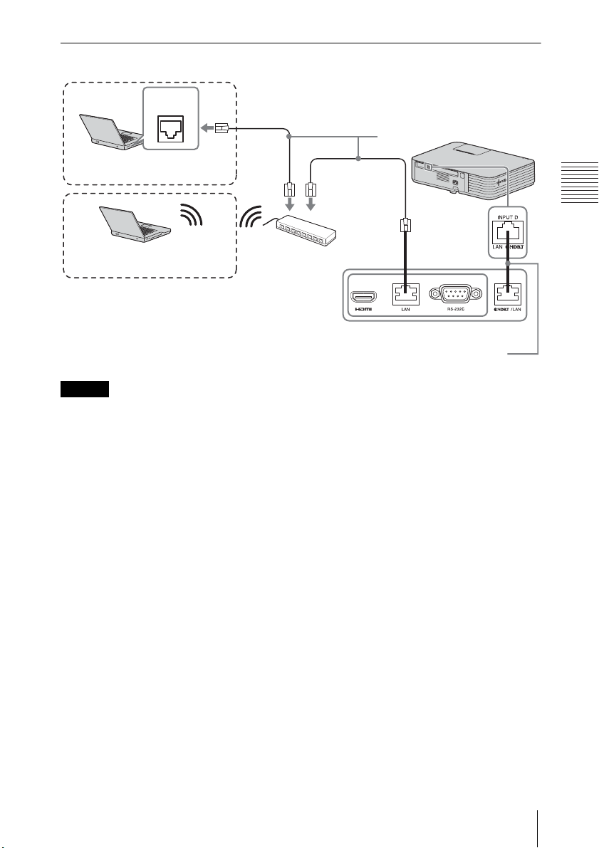
Connecting to the network equipment
Notes
Computer
LAN
terminal
Wired connection
LAN cable (straight type)
(not supplied)
Hub, Wireless router
HDBaseT transmitter
Computer
Wireless connection
LAN cable: STP type (CAT5e or
higher, straight, not supplied)
• If you are using a network, make sure “HDBaseT/LAN Port” is set to “HDBaseT”
(page 50).
• Connect this unit and the HDBaseT transmitter without a hub or router between
them.
Connecting the Projector
31
Page 32
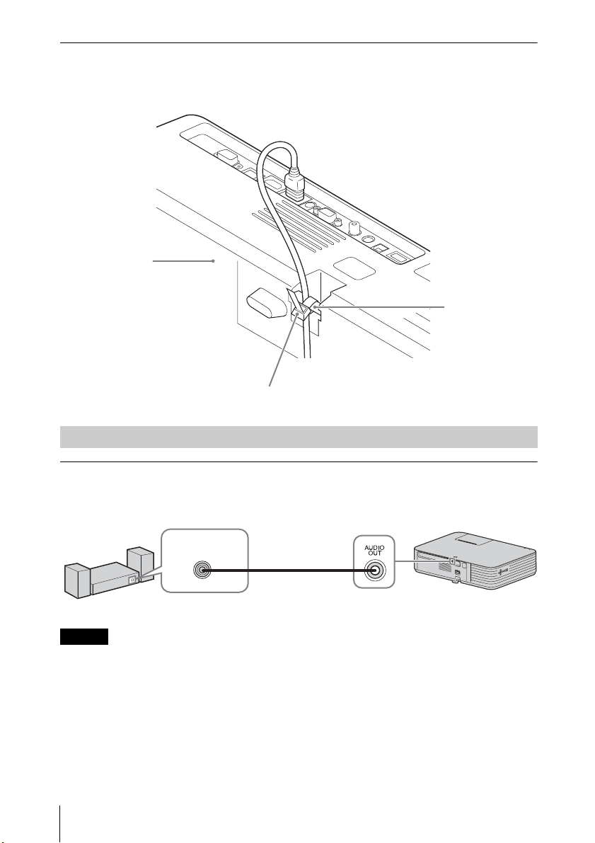
To attach the HDMI cable
Note
Security bar
Cable tie (commercially available)
Bottom of the
projector
Audio cable
(stereo mini plug)
(not supplied)
Audio input
terminal
Audio equipment
Fix the cable to the security bar at the bottom of the projector using a
commercially-available cable tie, as in the illustration.
Connecting Audio Equipment
OUTPUT
Input audio can be output to audio equipment such as speakers with a built-in
amplifier.
When the speaker setting is set to “Always On” and the light is turned off, INPUT A
is enabled.
32
Connecting the Projector
Page 33
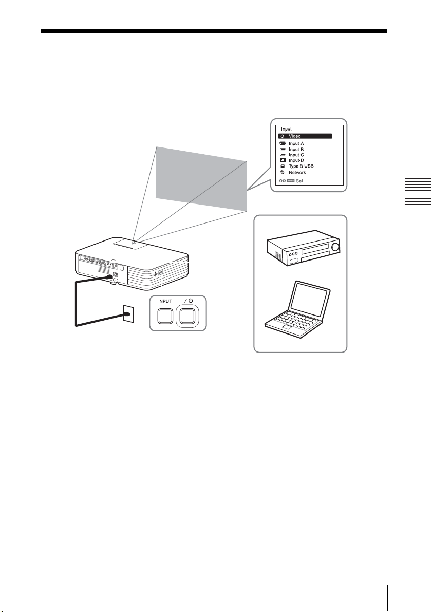
Projecting/Adjusting an Image
Computer
Video equipment
Projector
Wall outlet
1
2
5
4
3
6
Projecting/Adjusting an Image
Projecting an Image
The size of a projected image depends on the distance between the projector and
screen. Install the projector so that the projected image fits the screen size. For
details on projection distances and projected image sizes, see “Projection Distance
and Lens Shift Range” (page 97).
1 Plug the AC power cord into the wall outlet.
2 Connect all equipment to the projector (page 25).
3 Press the / key to turn on the unit.
4 Turn on the connected equipment.
5 Select the input source.
Press the INPUT key on the projector to display the menu for switching input
signal on the screen. Press the INPUT key repeatedly, or press the / key to
select an image to be projected.
Projecting an Image
33
Page 34
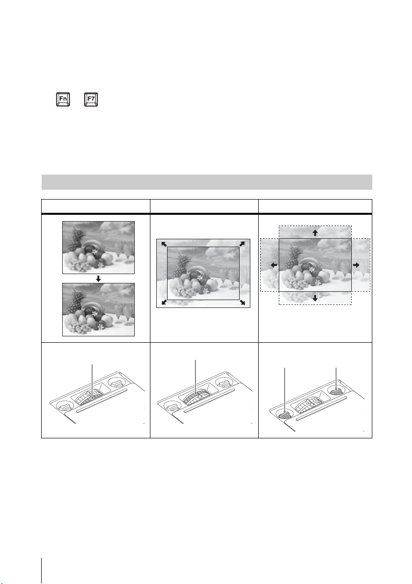
6 When projecting a computer image, switch your computer’s output to
Focus lever
Zoom lever
V lens
shift dial
H lens
shift dial
external display.
The method to switch the output varies depending on the type of
computer.
(Example)
+
To play video and audio using USB Connection, see “Playing Video and Audio
using USB Connection” (page 80). To use Presentation Function via Network,
see “Presentation Function via Network” (page 70).
7 Adjust the focus, size and position of the projected image (page 34).
Adjusting the Focus, Size, and Position of the Projected Image
Focus Size (Zoom) Position (Lens shift)
34
Projecting an Image
Page 35
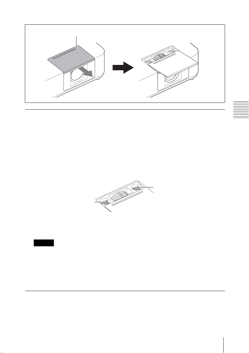
Projecting/Adjusting an Image
Slide the lens shift adjustment cover as below.
Notes
Lens shift adjustment cover
V lens shift dial
H lens shift dial
Adjusting the tilt of the projector by using lens shift
You can adjust the position of the projected image by turning the lens shift dials (H
lens shift dial, V lens shift dial).
1 Slide the lens shift adjustment cover to open.
For details, see page 35.
2 Turn the H lens shift dial (for adjusting right and left), V lens shift dial
(for adjusting up and down) to adjust lens shift.
If you keep turning the lens shift dials, the lens shift positions are restored to
the original positions. Keep turning to find the best positions. For details on the
adjustment range, see the “Lens shift range” (page 99).
• While adjusting the lens shift, be careful not to look into the lens.
• When turning the H lens shift dial, the lens shift may move up or down. (When
turning the V shift dial, the lens shift may move right or left.) In that case, adjust
the lens shift with each dial again.
3 Slide the lens shift adjustment cover to close.
Adjusting the tilt of the projector with the front feet (adjustable)
By changing the slope of the projector with front feet (adjustable), you can adjust
the position of the projected image.
Projecting an Image
35
Page 36
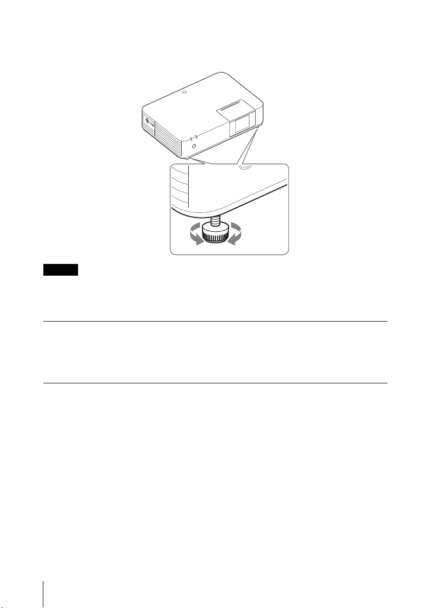
How to alter the angle
Notes
When the projector is installed on an uneven surface, you can adjust using the
front feet (adjustable).
• Be careful not to let the projector down on your fingers.
• Do not push hard on the top of the projector with the front feet (adjustable)
extended. It may cause malfunction.
Changing the aspect ratio of the projected image
Press the ASPECT key on the remote commander to change the aspect ratio of the
projected image. You can also change the setting in Aspect of the Screen menu
(page 44, 46).
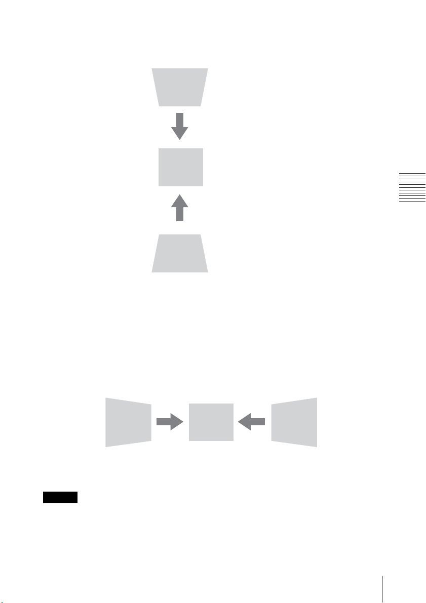
Correcting trapezoidal distortion of the projected image (Keystone feature)
If the image becomes trapezoidal, set the keystone manually.
When the projected image is a trapezoid, tapering to the top or bottom
1 Press the KEYSTONE key on the remote commander once or select “V
Keystone” in the Installation menu.
36
Projecting an Image
Page 37
Projecting/Adjusting an Image
Notes
Increase the number
towards plus
Increase the number
towards minus
Increase the number
towards plus
Increase the number
towards minus
2 Use the /// keys to set the value. The higher the setting, the narrower
the top of the projected image. The lower the setting, the narrower the
bottom.
Press the RESET key to restore the Projected image before adjustment.
When the projected image is a trapezoid, tapering to the right or left
1 Press the KEYSTONE key on the remote commander twice or select “H
Keystone” in the Installation menu.
2 Use the /// keys to set the value. The higher the setting, the narrower
the right part of the projected image. The lower the setting, the narrower
the left part.
Press the RESET key to restore the projected image before adjustment.
• Since the Keystone adjustment is an electronic correction, the image may be
deteriorated.
• Depending on the position adjusted with the lens shift feature, the aspect ratio
of the image may change from the original or projected image may be distorted
with Keystone adjustment.
Projecting an Image
37
Page 38
• If adjusting upwards or downwards (V keystone adjustment) and to the right or
Adjust using this cursor.
left (H keystone adjustment) at the same time, the values of the adjustment
menu may not reach the maximum value.
• If you press the KEYSTONE key on the remote control to switch the keystone
adjustment and corner key stone adjustment, the value of the adjustment menu
and the status of the image may not match before the adjustment is performed.
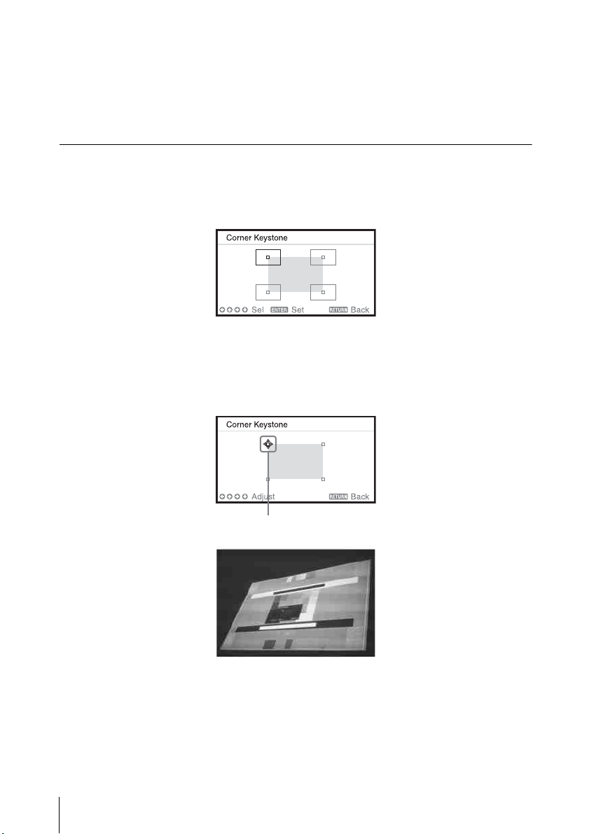
Correcting the image twist (Corner Keystone feature)
You can correct the image twist by the corner keystone feature.
Press the KEYSTONE key on the remote commander three times, or select “Corner
Keystone” in the Installation menu, and select “Adjust.” The guide is displayed.
The corners of the image to be corrected
1 Move the by using the /// keys to select the corner you want to
correct.
If you press the ENTER key, you will go back to the cursor display.
38
Projecting an Image
Page 39
Projecting/Adjusting an Image
Note
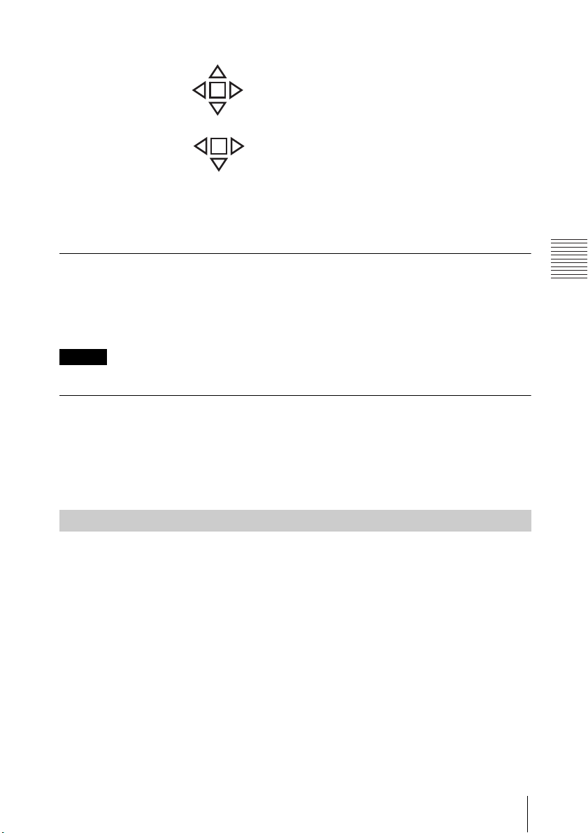
Example of cursor display:
You can adjust in all directions.
You can adjust only to the left/
right or downwards.
2 Adjust the position of the corner you want to correct by using the ///
keys. The cursor will disappear if the adjustment range limit is reached.
Press the RESET key to restore the projected image before adjustment.
Displaying a pattern
You can display a pattern for adjusting the projected image or a grid pattern with
the PATTERN key on the remote commander. Press the PATTERN key again to
restore the previous image. You can use a grid pattern as a guide to write text or to
draw lines and shapes on the whiteboard or blackboard without using a computer.
You cannot use this key when “Type B USB” or “Network” is selected as the input.
Automatically adjusts Phase, Pitch and Shift of projected image while a signal is input
from a computer (APA (Auto Pixel Alignment))
Press the APA key on the remote commander. Press again to cancel adjusting
during the setting.
You can also set APA in the Screen Menu (page 44). If Smart APA in the Function
menu is set to “On”, executes APA automatically when a signal is input (page 47).
Turning Off the Power
1 Press the / key on the unit or the remote commander.
The projector starts shutdown and turns off.
2 Unplug the AC power cord from the wall outlet.
Projecting an Image
39
Page 40
Adjustments and Settings Using a
Note
Setting menu
80
50
50
50
5
Picture Mode Standard
Reset
Contrast
Brightness
Color
Hue
Color Temp.
Sharpness
Expert Setting
:Sel :Set :Back
Picture
Low
Setting items
Adjust
Back
Contrast
Menu
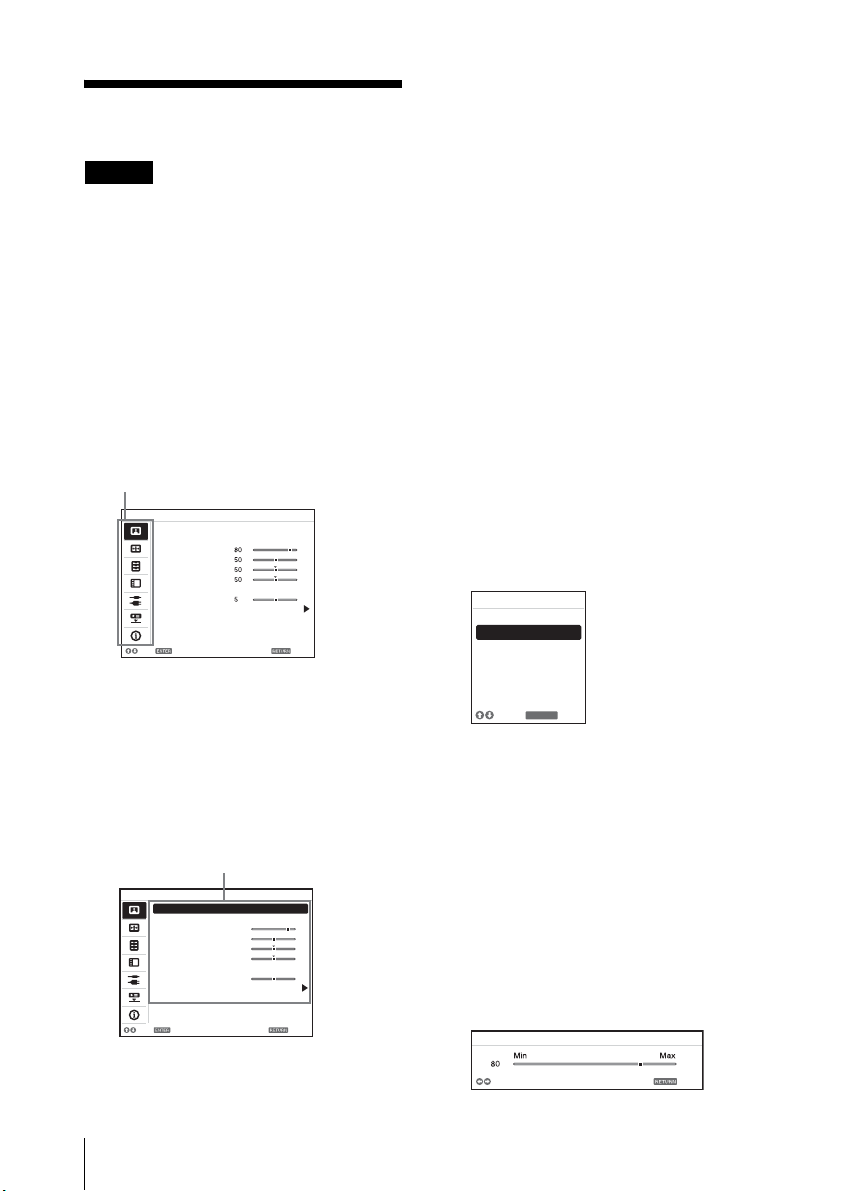
Using a MENU
The menu displays used for the
explanation below may be different
depending on the model you are
using.
1 Press the MENU key to display the
menu.
2 Select the setting menu.
Use the / key to select the
setting menu then press the key
or ENTER key.
Picture
Picture Mode Standard
Reset
Contrast
Brightness
Color
Hue
Color Temp.
Sharpness
Expert Setting
:Sel :Set :Back
Low
4 Make the setting or adjustment
for the selected item.
The setting method varies,
depending on the setting item.
If the next menu window is
displayed, select the item
according to the operations in step
3 and then press the ENTER key to
register the setting.
To return to the selection screen of
the setting items, press the or
RETURN key. You can press the
RESET key to reset an item to its
factory setting value to aid setting.
Using a pop-up menu
Press the /// key to select an
item.
Selected items take effect
immediately, except “Language,”
“Speaker Setting,” and “Input-A
Signal Sel.”, which take effect after
you press the ENTER key.
Picture Mode
Dynamic
Standard
Presentation
3 Select the setting item.
Use the / key to select the
setting menu then press the key
or ENTER key.
To return to the selection screen of
the setting menu, press the or
RETURN key.
40
Using a MENU
:Back
RETURN
:Sel
Using the setting menu
Press the / key to select the
item.
Press the ENTER key to register the
setting and return to the previous
screen.
Using the adjustment menu
To increase the value, press the /
key and to decrease the number,
press the / key. Press the ENTER
key to register the setting and
return to the previous screen.
Page 41

Adjustments and Settings Using a Menu
5 Press the MENU key to clear the
menu.
The menu disappears
automatically if no operation is
performed.
Using a MENU
41
Page 42
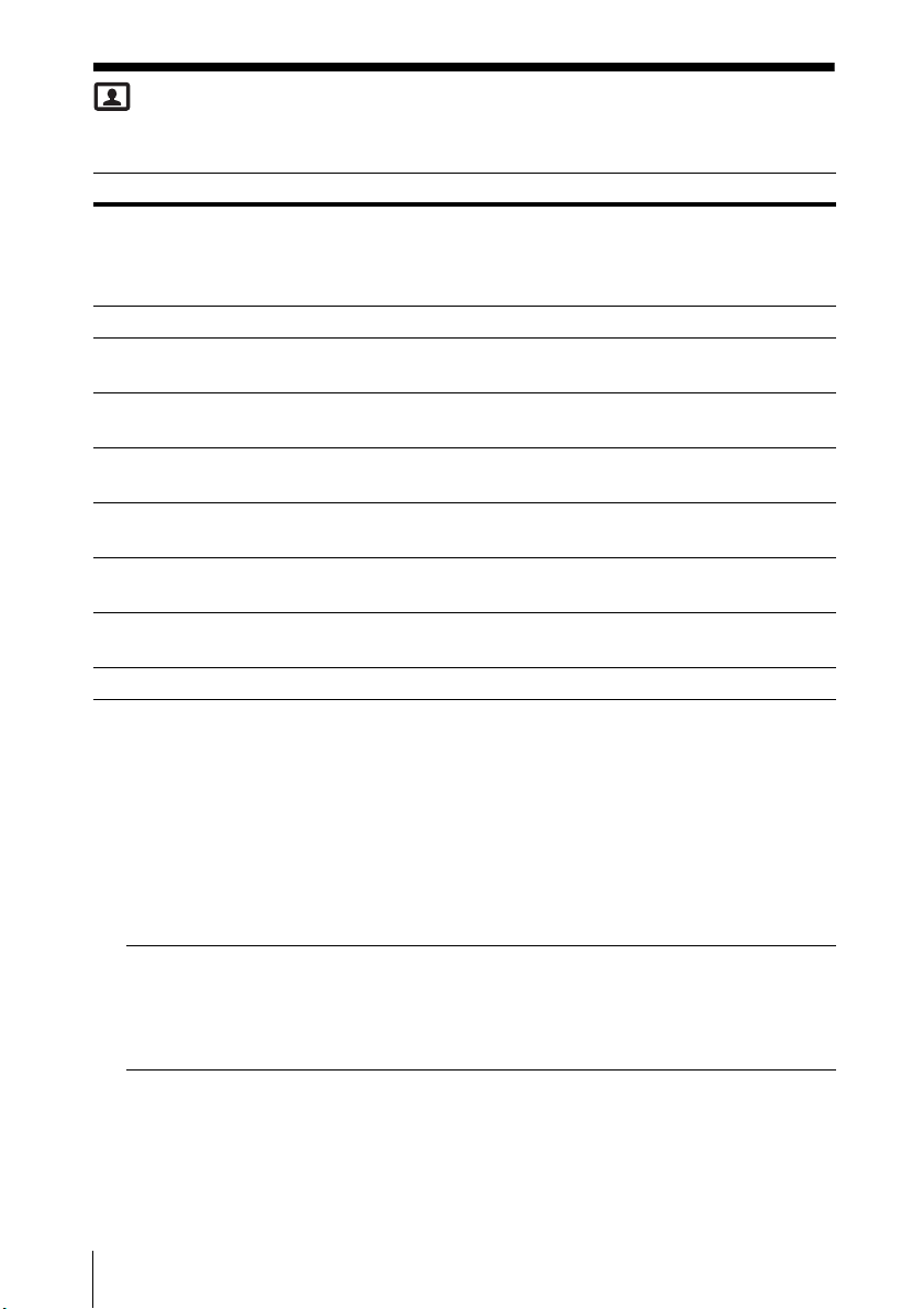
The Picture Menu
The Picture menu is used to adjust the picture for each input signal.
Setting items Item descriptions
Picture Mode Dynamic: Emphasizes the contrast to produce a dynamic and vivid
picture.
Standard: Provides an image which is natural and well balanced.
Presentation: Provides a bright image, suitable for presentations.
*1
Reset
Contrast The higher the value, the greater the contrast. The lower the value,
Brightness The higher the value, the brighter the picture. The lower the value,
*2 *3
Color
*2 *3 *4
Hue
Color Temp.
Sharpness The higher the value, the sharper the picture. The lower the value,
Expert Setting
Reality
Creation
Contrast
Enhancer
Resets the factory setting.
the lower the contrast.
the darker the picture.
The higher the value, the greater the intensity. The lower the value,
the lower the intensity.
The higher the value, the more greenish the picture becomes. The
lower the value, the more reddish the picture becomes.
*5
High/Middle/Low: The higher the value, the more bluish the
picture. The lower the value, the more reddish the picture.
the softer the picture.
Adjusts the detail and noise processing of images. (Super-resolution
function)
On: Adjusts the settings of “Reality Creation.”
Resolution: When you increase the setting value, the texture
and detail of the image become sharper.
Noise Filtering: When you increase the setting value, the noise
(picture roughness) becomes less prominent.
Test: On/Off: Switches “On” and “Off” at a certain frequency to
check the effect of “Reality Creation.”
Off: The “Reality Creation” function is not applied.
Corrects the level of bright and dark parts automatically to optimize
contrast according to a scene. Increases image sharpness and
makes image dynamic.
High/Middle/Low: You can adjust the contrast enhancer.
Off: The “Contrast Enhancer” function is not applied.
*6
42
The Picture Menu
Page 43
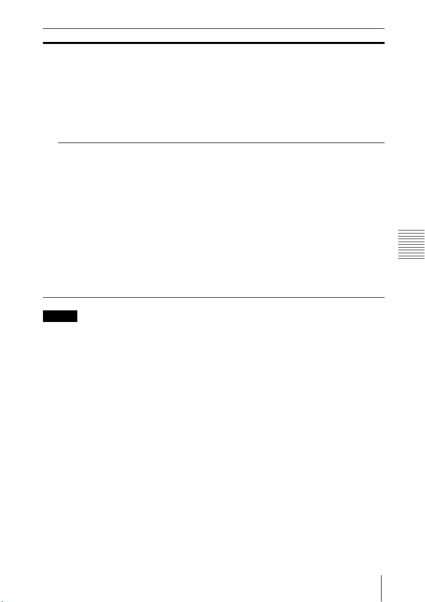
Adjustments and Settings Using a Menu
Notes
Setting items Item descriptions
Gamma
Mode
Color
Space
2.2: Equivalent to a 2.2 gamma curve.
2.4: Equivalent to a 2.4 gamma curve.
Gamma 3: Applies a gamma curve that prioritizes the brightness to
suit use in a relatively bright environment.
Gamma 4: Enhances black and white contrast to suit use in a
relatively dark environment.
DICOM GSDF Sim.
Grayscale Standard Display Function (GSDF) of the Digital Imaging
and Communications in Medicine (DICOM) standards.
Converts the color space.
Custom 1: Produces images with vivid colors.
Custom 2: Produces images with muted colors.
Custom 3: Reproduces image colors true to the original image
source.
You can select R/G/B for the selected color space and adjust the R/
G/B chromaticity points in the x and y directions in the CIExy
chromaticity diagram respectively.
Color Select: Select the color to adjust from “Red,” “Green,” and
“Blue.”
*7
: Gamma setting is in accordance with the
Cyan - Red (x): Adjusts the chromaticity point of the selected
color toward cyan-red (x).
Magenta - Green (y): Adjusts the chromaticity point of the
selected color toward magenta-green (y).
*1: The settings in the Picture menu return to their factory defaults, except for Picture
Mode.
*2: When a video signal is input, this option is available.
*3: When the signal without color burst signal is input after selecting “Video”, this
option is unavailable.
*4: When an analog TV signal is input, this option may not be available, depending on
the color system.
*5: When “Picture Mode” is set to the item other than “Presentation,” this option is
available.
*6: The display position of the status during the test works together with the “Menu
Position” setting (page 49).
*7: Available when a computer signal is input from the HDMI input terminal (INPUT B,
C) or HDBaseT (INPUT D). This projector is not to be used as a device for medical
diagnosis.
The Picture Menu
43
Page 44
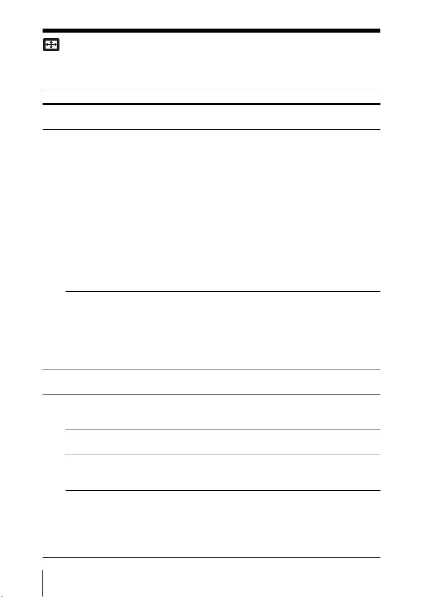
The Screen Menu
The Screen menu is used to adjust the size, position and aspect ratio of the
projected image for each input signal.
Setting items Item descriptions
*1
Aspect
When the computer
signal is input
When the video
signal is input
Adjust Signal Adjusts the image of computer signal. Use this item if the
*2 *3
APA
*2
Phase
*2 *5
Pitch
*4
Shift
Changes the aspect ratio of the projected image
(page 46).
4:3: Displays the image to fit the maximum projected
image size with an aspect ratio fixed to 4:3.
16:9: Displays the image to fit the maximum projected
image size with an aspect ratio fixed to 16:9.
Full 1: Displays the image to fit the maximum projected
image size without changing the aspect ratio of the input
signal.
Full 2: Displays the image to fit the maximum projected
image size changing the aspect ratio of the input signal.
Full 3: Displays the image to fit the maximum width or
height, up to 1280 × 720 pixels, without changing the
aspect ratio of the input signal.
Normal: Displays the image on the center position of the
projected screen without changing the resolution of the
input signal or enlarging the image.
4:3: Displays the image to fit the maximum projected
image size with an aspect ratio fixed to 4:3.
16:9: Displays the image to fit the maximum projected
image size with an aspect ratio fixed to 16:9.
Full: Displays the image to fit the maximum projected
image size changing the aspect ratio of the input signal.
Zoom: Zooms the center area of a projected image.
edge of the image is cut and reception is bad.
Automatically adjusts the projected image to an
optimum quality when you press the ENTER key
(page 22).
Adjusts the dot phase of the display pixel and the input
signal. Set to the value where looks clearest.
The higher the value, the wider the horizontal image
elements (pitch). The lower the value, the narrower the
horizontal image elements (pitch).
H: The higher the value, the farther right the image is
projected on the screen. The lower the value, the image
farther left.
V: The higher the value, the farther up the image is
projected on the screen. The lower the value, the image
farther down.
44
The Screen Menu
Page 45

Adjustments and Settings Using a Menu
Notes
*1: • Note that if the projector is used for profit or for public viewing, modifying the
original picture by switching to the aspect mode may constitute an infringement
of the rights of authors or producers, which are legally protected.
• Depending on the input signal, setting items for aspect ratio or some other
setting items cannot be set in some cases, or changing the aspect ratio setting
may have no effect.
• A part of the image may be displayed in black, depending on the setting item.
*2: Available when a computer signal is input from the RGB input terminal (INPUT A).
*3: If the projected image includes large amount of black portion around it, the APA
function will not work properly and a part of the image may not be displayed on the
screen and also optimum image cannot be obtained, depending on the type of
input signal. In this case, adjust the “Phase,” “Pitch,” and “Shift” items manually.
*4: Available when a computer or a video signal is input from the RGB/YPBPR input
terminal (INPUT A).
*5: When “APA” (page 44) or “Smart APA” (page 47) is performed, the adjusted value
for “Pitch” will return to its factory default. If you want to continue using the
adjusted value, set “Smart APA” to “Off.”
The Screen Menu
45
Page 46
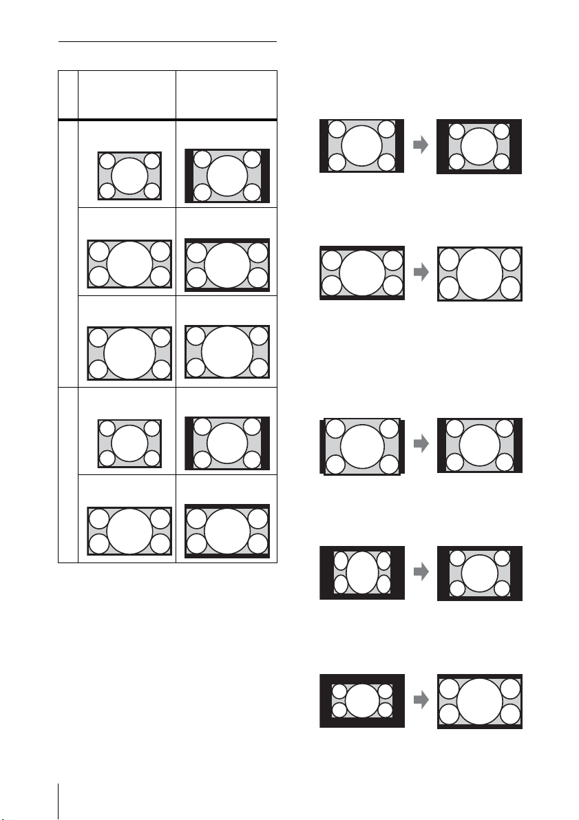
Aspect
Input signal
4:3 Full1
16:9 Full1
Recommended
setting value and
projected image
*1 *2 *3
*1 *2 *3
*1: If you select “Normal,” the image is
projected in the same resolution as
the input signal without changing
the aspect ratio of the original
image.
*2: If you select “Full2,” the image is
projected to fit the projected image
size, regardless of the aspect ratio of
the image.
Computer signal
16:10 Full1
*3
*3: If you adjust the projected image
position using an image with 16:9
aspect ratio and then switch the
input source to 4:3 image, the top
and bottom edge of the image may
4:3 4:3
*4 *5
16:9 16:9
Video signal
be hidden. In this a case, select
“Full3.”
*4: Depending on the input signal, the
projected image may be projected as
illustrated below. In this a case,
select “16:9.”
*5: Depending on the input signal, the
image may be projected as
illustrated below. In this a case,
select “Zoom.”
46
The Screen Menu
Page 47
Adjustments and Settings Using a Menu
Notes
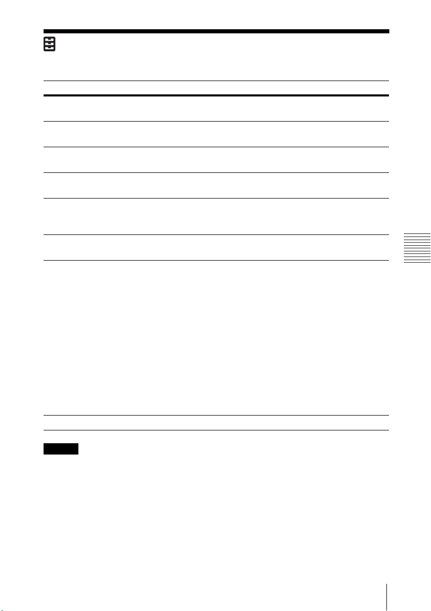
The Function Menu
The Function menu is used for setting various functions of the projector.
Setting items Item descriptions
Volume The higher the value, the louder an audio volume and the
lower the value, the lower the audio volume.
Speaker On/Off: When set to “On,” speaker outputs sound. To not
output sound from the speaker, select “Off.”
Speaker Setting Sync with Power/Always On: When set to “Always On,” the
speaker is available even in Light Cutoff.
Smart APA On/Off: When set to “On,” APA functions automatically when
a signal is input.
CC Display CC1/CC2/CC3/CC4/Text1/Text2/Text3/Text4: Select the
closed caption service (captions or text).
Off: Closed caption does not appear.
Start Up Image On/Off: When set to “On,” the Start Up Image is displayed on
the screen when the projector is powered on.
*3*4
Color Calibration
All Reset Resets all settings to their factory defaults.
Corrects the color drifts of the entire screen that occurred
overtime.
Auto
If you select “On”, it corrects the color drifts of the entire
screen automatically when turning off the projector after
certain time of use.
Start
If 20 minutes have passed after the light turning on, it
immediately corrects the color drifts of the entire screen.
*5
Return
Restores the color to that before performing the previous
color calibration.
Reset
Restores the factory setting.
*2
*1
*1: When the speaker setting is set to “Always On” and the light is turned off, INPUT A
is enabled.
If “Always On” is selected, “ECO Mode” will be set to “User,” “Standby Mode” will be
set to “Standard” in conjunction.
*2: APA functions when a computer signal is input via the RGB input terminal (INPUT A).
*3: The pattern for the color calibration is displayed while performing this mode.
If you press the / button on the projector or remote control, the pattern also turns
off. At the same time, this mode also ends.
*4: Color drifts may not be able to be corrected correctly because of environmental
factors, such as temperature and dust, or the extent of changes that occurred
overtime.
The Function Menu
47
Page 48

*5: Cannot be selected if you have not performed the color calibration.
48
The Function Menu
Page 49
Adjustments and Settings Using a Menu
Note
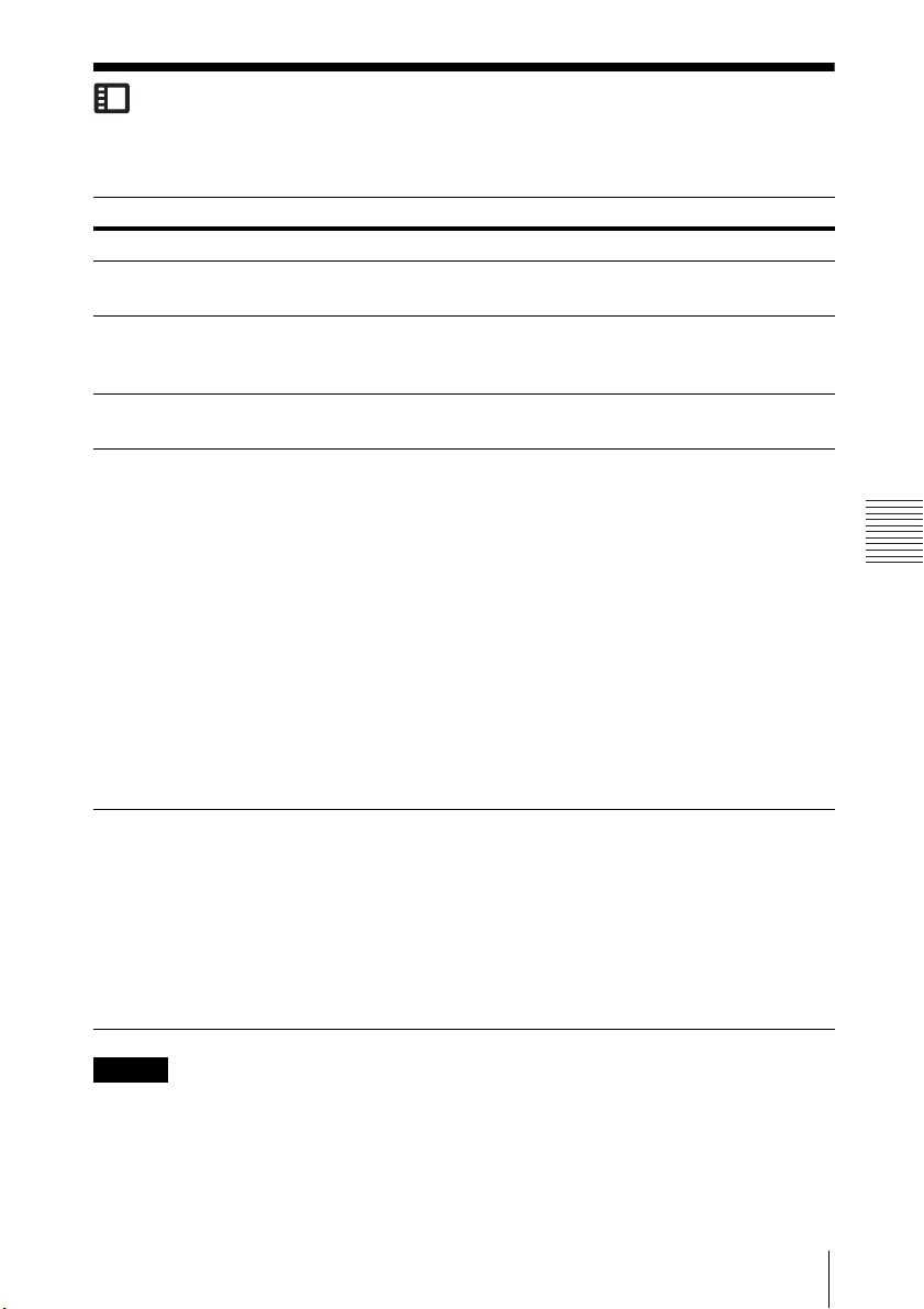
The Operation Menu
The Operation menu is used for setting for the operations by using the menu or the
remote commander.
Setting items
Language Selects the language used in the menu and on-screen displays.
Menu
Position
Status On: All on-screen statuses are enabled.
IR Receiver Front & Rear/Front/Rear: Selects the remote control receiver (IR
Security
*1
Lock
Control Key
Lock
Item descriptions
Bottom Left/Center: For selecting the position of the menu displayed
on the projected image.
Off: Displays only the menus, the message when turning off the power,
and warning messages.
Receiver) on the front and rear of the projector.
On/Off: This function enables restriction of the projector to authorized
users by password. The setting procedures for security locking are as
follows:
1
Select “On” and press the ENTER key to display the setting menu.
2
Input the password with the MENU, /// and ENTER keys.
(The default setting password is “ENTER, ENTER, ENTER, ENTER.”)
3
Input a new password with the MENU, /// and ENTER keys.
4
Enter the password again to confirm.
Enter the password when you turn on the projector after disconnecting
and reconnecting the AC power cord.
When it is set to “Off,” you can cancel the security lock. You are required
to input the password again.
If you fail to enter the correct password after three consecutive times,
the projector cannot be used. In this case, press the / key to go
Standby mode then turn on the power again.
On/Off: When set to “On,” locks all the control panel keys of the
projector. However, you can operate the following when set to “On”:
Press and hold the / key for approximately 10 seconds during
Standby mode.
The projector turns on.
Press and hold the MENU key for approximately 10 seconds during
power on.
“Control Key Lock” is set to “Off” and enables operation of all
keys on the projector.
*1: You will not be able to use the projector if you forget your password. If you call
qualified Sony personnel because you have forgotten the password, you will be
asked to verify the projector’s serial number and your identity. (This process may
differ in other countries/regions.) Once your identity has been confirmed, we will
provide you with the password.
The Operation Menu
49
Page 50

The Connection/Power Menu
The Connection/Power menu is used for setting for the connections and power.
Setting items Item descriptions
LAN Settings
IP Address
*1
Setup
WLAN Settings
WLAN
Connection
WLAN
Network
HDBaseT setting Sets the function of the HDBaseT/LAN Port.
HDBaseT/LAN
Port
RS-232C
setting
Network Presentation
Connection
CODE
Display Setting
*3
Auto (DHCP): The IP address is assigned automatically from
the DHCP server such as a router.
Manual: To specify the IP Address manually.
On/Off: Set the wireless output of the USB wireless LAN
*2
module (not supplied) to On/Off.
Access Point/Client *4: Changes modes for WLAN.
HDBaseT: Connecting the HDBaseT transmitter and the LAN
cable enables transmitting the signal of the Video, Audio,
Ethernet, and RS-232C.
LAN: Connecting the LAN cable for Ethernet directly enables
connecting to the network.
(Use when connecting the cable directly without the HDBaseT
transmitter.)
Via HDBaseT: You can connect this unit to the RS-232C
terminal via the HDBaseT transmitter. (Baud rate: 9600bps)
RS-232C: Use when connecting to the RS-232C terminal of this
unit directly.
On/Off: This is the presentation function via the network. It
controls the connection using the displayed number (CODE)
on the right bottom of the screen. During the image
transmission, using the ENTER key on the remote commander
makes Connection CODE display again.
LAN Mode Displays the LAN settings of the projector or the
settings of the USB wireless LAN module that
operates as a client at the bottom right of the
screen.
Wired: Displays the IP address of LAN
preferentially.
Wireless: Displays the IP address of the USB
wireless LAN module preferentially.
AP Mode Displays the SSID of the USB wireless LAN
module that operates as an access point at the
bottom right of the screen.
*5
50
The Connection/Power Menu
Page 51
Adjustments and Settings Using a Menu
Setting items Item descriptions
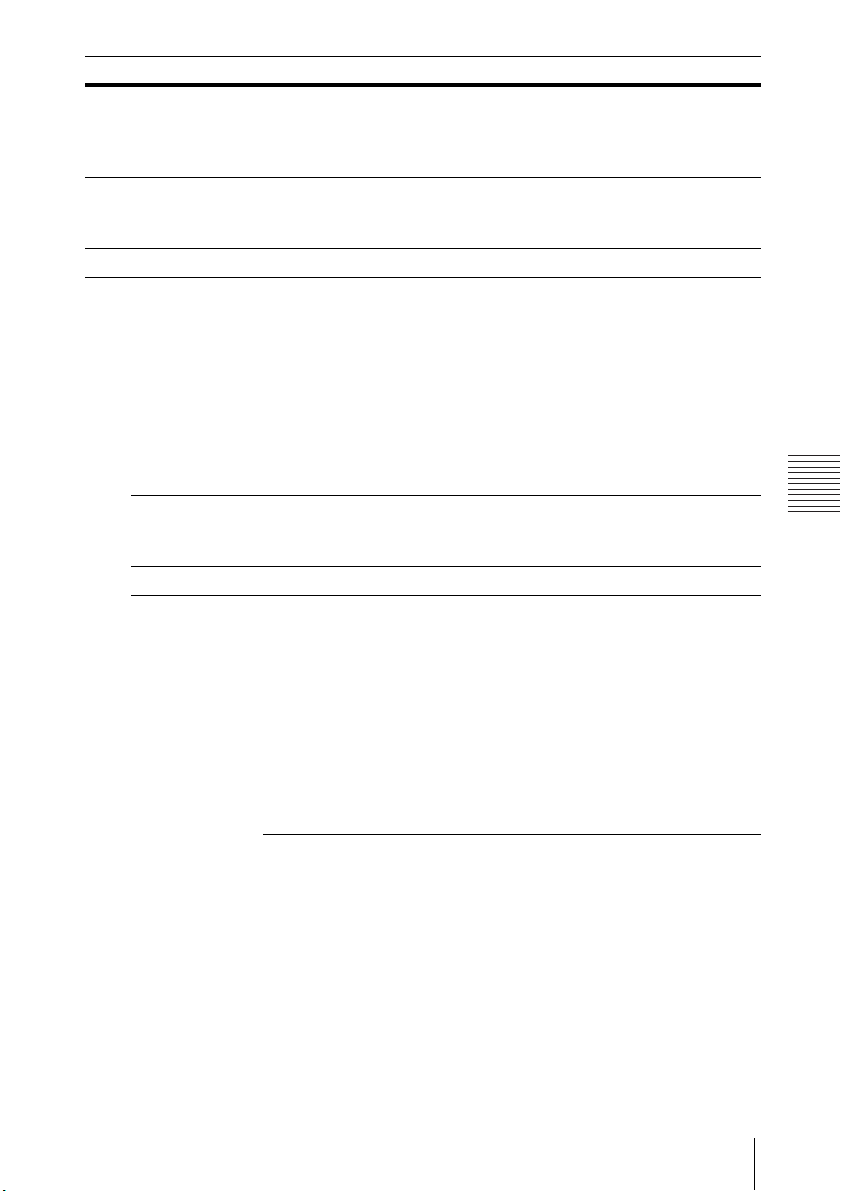
Dynamic Range
*6
Sets the image input level of the INPUT B/C/D terminal.
Auto: Distinguishes the image input level automatically.
Limited: Set when the image input level is 16-235.
Full: Set when the image input level is 0-255.
Input-A Signal Sel. Auto/Computer/Video GBR/Component: When set to
“Auto”, selects the type of video signal input automatically
when “Input-A” is selected.
*7
ECO
*8 *9
Light Output
Mode
Standard/Middle/Low/Auto
image becomes brighter, and power consumption becomes
: When set to “Standard,” the
higher. When set to “Low,” power consumption is minimized;
however, the image will be darker. If you select ”Middle”, the
brightness of the image and power consumption change to
the middle of “Standard” and “Low.” When set to “Auto,”
brightness is adjusted automatically according to image
content. Dark images are projected with brightness adjusted,
leading to energy-saving. Bright images are projected
brightly, without adjusting brightness.
Constant
Brightness
On/Off: Available when Light Output Mode is set to
*10
"Standard" or "Middle." Brightness is constant at about 90% of
light output of each mode.
Auto Power Saving
With No
Input
Light Cutoff: The light turns off automatically
and power consumption is reduced if no signal
is input for approx. 2 minutes. The light lights
again when a signal is input or any key is
pressed. In Light Cutoff, the ON/STANDBY
indicator lights in orange. (page 82)
*11
Standby
: If no signal is input to the unit for
approx. 2 minutes, the power turns off
automatically, and the unit enters standby
mode.
Off: You can deactivate the With No Input.
The Connection/Power Menu
51
Page 52

Notes
Setting items Item descriptions
*8 *12 *13
With Static
Signal
Light Dimming
change for about 10 seconds, light output is
gradually reduced (approximately 10% to
*14
) from that set in the Light Output Mode.
15%
: If an image does not
Automatically the light slowly darkens to
approximately 5% of its light output according
to the selected time (with no change to input
signal) “5 min.”, “10 min.”, “15 min.”, “20 min.” or
“Demo.”, While dimming the light, the message
“Light Dimming” appears. If you select “Demo.,”
the image will start to darken about 40 seconds
later. When any change in signal is detected, or
an operation (remote control or control panel) is
performed, normal brightness is restored.
Off: You can deactivate the With Static Signal.
Standby
*15
Mode
Standard/Low: When set to “Standard,” power consumption
becomes higher in Standby mode. For details, see “Power
consumption (networked standby mode)” in “Specifications”
(page 93).
Direct Power On On/Off: When set to “On”, you can turn the power on without
going to Standby mode when the AC power cord is connected
to a wall outlet. With the projector turned off, you can also
unplug the AC power cord without going to Standby mode,
regardless of the Direct Power On setting.
*1: To set the IP address manually, select “Manual”, press “Apply”, then enter the IP
address.
*2: Reflecting changes in WLAN settings may take a few moments.
*3: If the projector cannot connect wirelessly, click [Apply] once again to make sure the
connection is established. For details, see “Setting the WLAN Network of the
projector” (page 61).
*4: The factory default settings for “Access Point” are as follows.
SSID: VPL + MAC address for LAN
Security Method: WEP(64bit)
Wireless Password: sony1
To change the settings for “Access Point”, use a Web browser.
For details, see “Setting the WLAN Network of the projector” (page 61).
*5: For changing the settings for “Client,” use the Web browser for change. For details,
see “Setting the WLAN Network of the projector” (page 61).
*6: If the image input setting of the HDMI connection equipment is not correct, the
brighter part becomes too bright and the darker part becomes too dark.
*7: This may not be optimum depending on the input signal. In this case set manually
according to the connected equipment.
*8: This mode does not work for about three minutes after the light lights. A change in
signal may not be detected depending on the input image. The light may become
52
The Connection/Power Menu
Page 53

Adjustments and Settings Using a Menu
brighter at intervals during light dimming. However, this is not a malfunction. If
With No Input is set, it takes priority.
*9: Does not function when “Type B USB” or “Network” is selected as the input. In this
case, it becomes equivalent to “Middle.”
*10:Keeps brightness constant within a certain range. The projector may not be able to
maintain the brightness in an environment with a lot of dust and dirt.
*11: Select “Off” to avoid entering standby mode when there is no input signal.
*12: As the light is dimmed gradually, you may not notice any change in brightness. You
might only notice that the light has dimmed when its brightness is restored after
there is a change in input signal.
*13: Does not function when “Type B USB” or “Network” is selected as the input.
*14:This varies depending on the “Light Output Mode” setting.
*15: When “Standby Mode” is set to “Low,” the network and network control function
cannot be operated while the projector is in standby mode.
The Connection/Power Menu
53
Page 54
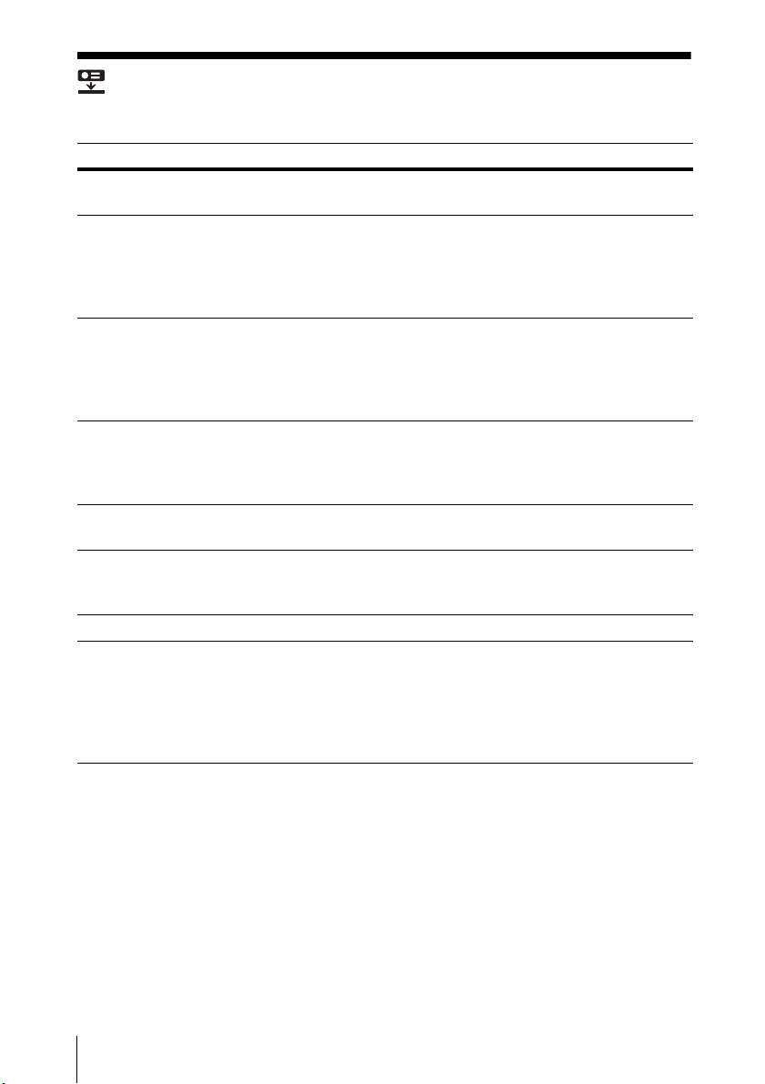
The Installation Menu
The Installation menu is used for installing the projector.
Setting items Item descriptions
Screen Fitting HV Keystone/ Corner Keystone: You can choose how to correct
image twist.
V Keystone
H Keystone
Corner Keystone
Image Flip HV/H/V/Off/Auto: Flips the projected image horizontally and/or
High Altitude
Mode
Filter Cleaning Turns off the projector and cleans the air filter.
Digital Shrink
*3*4*5
*1
*1
This is displayed when “HV Keystone” is selected in “Screen
Fitting.”
The higher the setting, the narrower the top of the projected
image. The lower the setting, the narrower the bottom of the
projected image.
This is displayed when “HV Keystone” is selected in “Screen
Fitting.”
The higher the setting, the narrower the right side of the
projected image. The lower the setting, the narrower the left side
of the projected image.
*1
This is displayed when “Corner Keystone” is selected in “Screen
Fitting.”
Adjust: Corrects image twist.
Reset: Resets the adjusted values to their default values.
vertically according to the installation method.
On/Off: Set to “On” when using the projector at an altitude of
1,500 m or higher. Continuing to use the wrong setting may affect
component reliability.
*2
Shrinks or adjusts the size of the projected image.
Digital Shrink: Adjusts the size of the projected image. If you set
the value to “0”, the image is set to the original size. The shrinking
rate is 100% to 90%.
Shift: Adjusts the position of the projected image. The adjustable
range varies from the shrinking rate.
54
The Installation Menu
Page 55
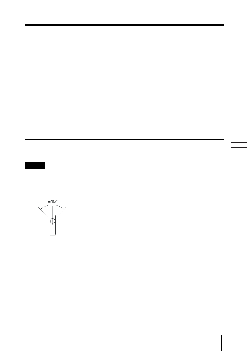
Adjustments and Settings Using a Menu
Notes
Setting items Item descriptions
Panel
Alignment
*6
This feature allows you to adjust the gaps in the color of
characters or the picture.
When set to “On,” “Adjust Color” and “Pattern Color” can be
assigned and adjusted.
Adjust Item: Selects how to make adjustments from below.
Shift: Shifts the whole picture and makes adjustments.
Zone: Selects the desired range and makes adjustments.
Adjust Color: Assigns the desired color to adjust the gaps in
color. Select “R” (Red) or “B” (Blue) to make adjustments based on
“G” (Green).
Pattern Co lor: Select “R/G” (Red and Green) or “R/G/B” (White,
all colors) when “Adjust Color” is “R” (Red). Select “B/G” (Blue and
Green) or “R/G/B” (White, all colors) when the “Adjust Color” is
“B” (Blue).
Adjust: The shift adjustment and zone adjustment of the color
selected in “Adjust Color” can be made with /// keys.
Reset: The panel alignment settings are initialized to their factory
preset values.
Color Matching
*1: Since the HV Keystone/Corner Keystone adjustment is an electronic correction, the
image may deteriorate.
*2: Normally, filter cleaning is performed automatically. However, it is not performed
when the projector is installed at an angel within the range illustrated below.
*7
Adjust/Reset: For correcting the brightness and color of the
whole projected image manually from the signal level in six steps.
*3: Since Digital Shrink uses electronic correction, the image may deteriorate.
*4: If you press the ENTER button while adjusting with Digital Shrink, the projector
switches to the shift adjustment.
*5: For VPL-PHZ11, the function is available when “Aspect” is set to an item other than
“4:3”.
*6: Depending on the adjustment value of “Panel Alignment,” the color and resolution
may be changed.
*7: The brightness and color of the projected image may not match completely, even
after you adjust “Brightness” and “Color.”
The Installation Menu
55
Page 56

The Information Menu
Note
The Information menu is used to check projector status, such as total usage time
of the light.
Setting items Item descriptions
Model Name Displays the model name.
Serial No. Displays the serial number.
*1
fH/fV
Signal Type Displays the type of the current input signal.
Light Timer Indicates the total usage time of a light.
*1: These items may not be displayed depending on the input signal.
Displays the horizontal/vertical frequency of the current input
signal.
56
The Information Menu
Page 57

Network
Network
Notes
Using Network Features
Connection to the network allows you to operate the following features:
• Checking the current status of the projector via a Web browser.
• Remotely controlling the projector via a Web browser.
• Receiving the e-mail report via the projector.
• Making the network settings for the projector.
• Displaying messages on the projected image using an application.
• Supports network monitoring, control protocol (Advertisement, ADCP, PJ Talk, PJ
Link, AMX DDDP [Dynamic Device Discovery Protocol], Crestron RoomView).
• When connecting this projector with the network, consult with the network
administrator. The network must be secured.
• The content communicated via a wireless LAN communication may be
intercepted due to the use of radio waves. To protect the communication
content, implement security measures properly according to the connection
environment (page 61).
• When using this projector connected with the network, access the Control
window via a Web browser and change the access limitation of the factory preset
values (page 58). It is recommended to change the password regularly.
• When the setting on the Web browser is completed, close the Web browser to
log out.
• The menu displays used for the explanation below may be different depending
on the model you are using.
• Supported Web browsers are Internet Explorer 8/9/10/11.
• The menu displays only in English.
• If the browser of your computer is set to [Use a proxy server] when you access to
the projector from your computer, click the check mark to set accessing without
using a proxy server.
• To display messages, specific application Projector Station for Network Control
(Version 1.1 or later) is necessary. For download or detailed method of using
Projector Station for Network Control, please access the following URL.
http://pro.sony.com/bbsc/ssr/cat-projectors/resource.downloads
Contact your local Sony dealer for detailed information of Projector Station for
Network Control.
Using Network Features
57
Page 58
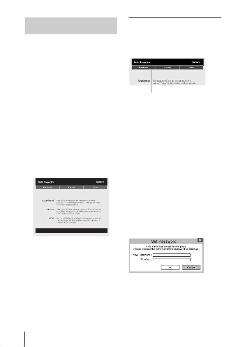
Displaying the Control Window of
Page Switch ing buttons
the Projector with a Web Browser
1 Connect the LAN cable (page 27).
2 Set the network settings for the
projector using “LAN Settings” on
the Connection/Power menu
(page 50).
3 Start a web browser on the
computer, enter the following in
the address field, then press the
Enter key on your computer.
http://xxx.xxx.xxx.xxx
(xxx.xxx.xxx.xxx: IP address for the
projector)
You can confirm the IP address of
the projector in the “LAN Settings”
on the Connection/Power menu
(page 50).
The following window appears in
the Web browser:
How to operate the Control window
Switching the page
Click one of the Page Switching
buttons to display the desired setting
page.
Setting the access limitation
You can limit a user for accessing any
particular page.
Administrator: Allowed access to
all pages
User: Allowed access to all pages
except the Setup page
Set the access limitation from
[Password] of the Setup page.
When you access the Setup page for
the first time, enter “root” in the Name
box and enter “Projector” in the
Password box of User.
When you log in for the first time, the
window that prompts you to change
the password is displayed. Follow the
instructions on the screen to change
the password.
The Name box of the Administrator is
preset to “root.”
Once you make the network
settings, you can open the Control
window only by performing step 3
of this procedure.
58
Using Network Features
Page 59
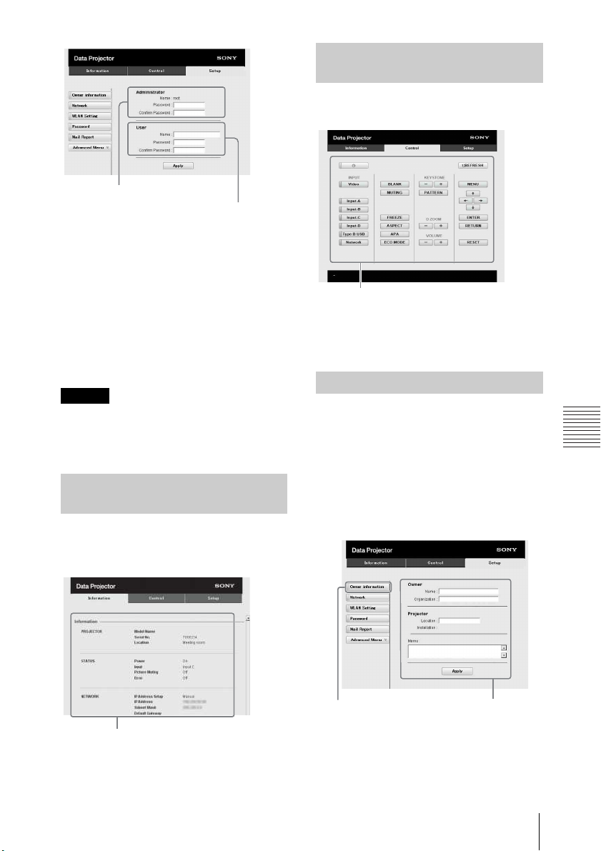
Network
Note
Entry area for [Administrator]
Entry area for [User]
Information area
Operating the Projector from a
Operation area
1
Owner information button
Computer
You can control the projector from the
computer on the Control page.
When you change the password, input
a new password after deleting the
password (*****) that was set.
The password of the administrator and
user should be 8 to 16 characters that
includes both alphabet and numeric
characters.
Alphabet is case-sensitive.
The default password “Projector”
cannot be set as a new password.
The functions of the buttons shown in
the operation area are the same as the
keys on the remote commander.
Using the e-mail report Function
If you forget your password, consult
with qualified Sony personnel.
The password will be reset with your
permission.
Set the e-mail report function on the
Setup page.
Entered values will not be applied
unless you click on [Apply].
Confirming the Information regarding the Projector
You can confirm the current settings
for the projector on the Information
page.
1 Click on [Owner information] to
enter the owner information
recorded in the e-mail report.
Using Network Features
59
Page 60
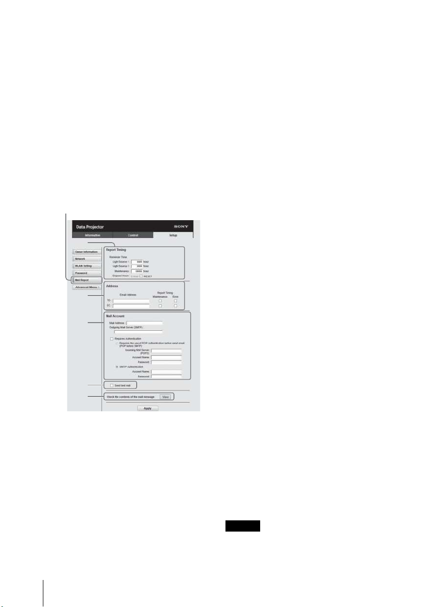
2 Set the timing of the e-mail
Notes
2
3
4
6
5
Mail Report button
report.
Click on [Mail Report] to open the
Mail Report page.
Light Source 1:
Set an arbitrary timing of the
email report for using the light.
Light Source 2:
This unit is not supported.
Maintenance:
Set the timing of the email report
for maintenance. To reset
Maintenance Reminder, check
the RESET check box and then
click on [Apply].
Outgoing Mail Server (SMTP):
Enter the address of outgoing
mail server (SMTP).
Required Authentication:
Check this check box if
authentication is required for
sending e-mail.
Requires the use of POP
Authentication before sending
email (POP before SMTP):
Check this check box to arrange
for POP authentication to be
performed before sending email.
Incoming Mail Server (POP3):
Enter the address of the
incoming-mail server (POP3) to
be used for POP authentication.
Account Name:
Enter the mail account name.
Password:
Enter the password.
SMTP Authentication:
Check this check box to arrange
for SMTP authentication to be
performed before sending email.
Account Name:
Enter the mail account name.
Password:
Enter the password.
3 Enter the outgoing e-mail
4 Set the mail account for sending
60
Using Network Features
address in the Email Address box
then check the Report Timing
check box of the e-mail report to
be sent.
e-mail reports.
Mail Address:
Enter the e-mail address.
5 Confirm the contents of the e-
mail report.
When you click on [View], the
contents of the e-mail report are
displayed.
6 Send the test mail.
Check on the Send test mail check
box then click on [Apply] to send
your test mail to the e-mail address
you set.
• The email report function will not
work if the network uses Outbound
Page 61
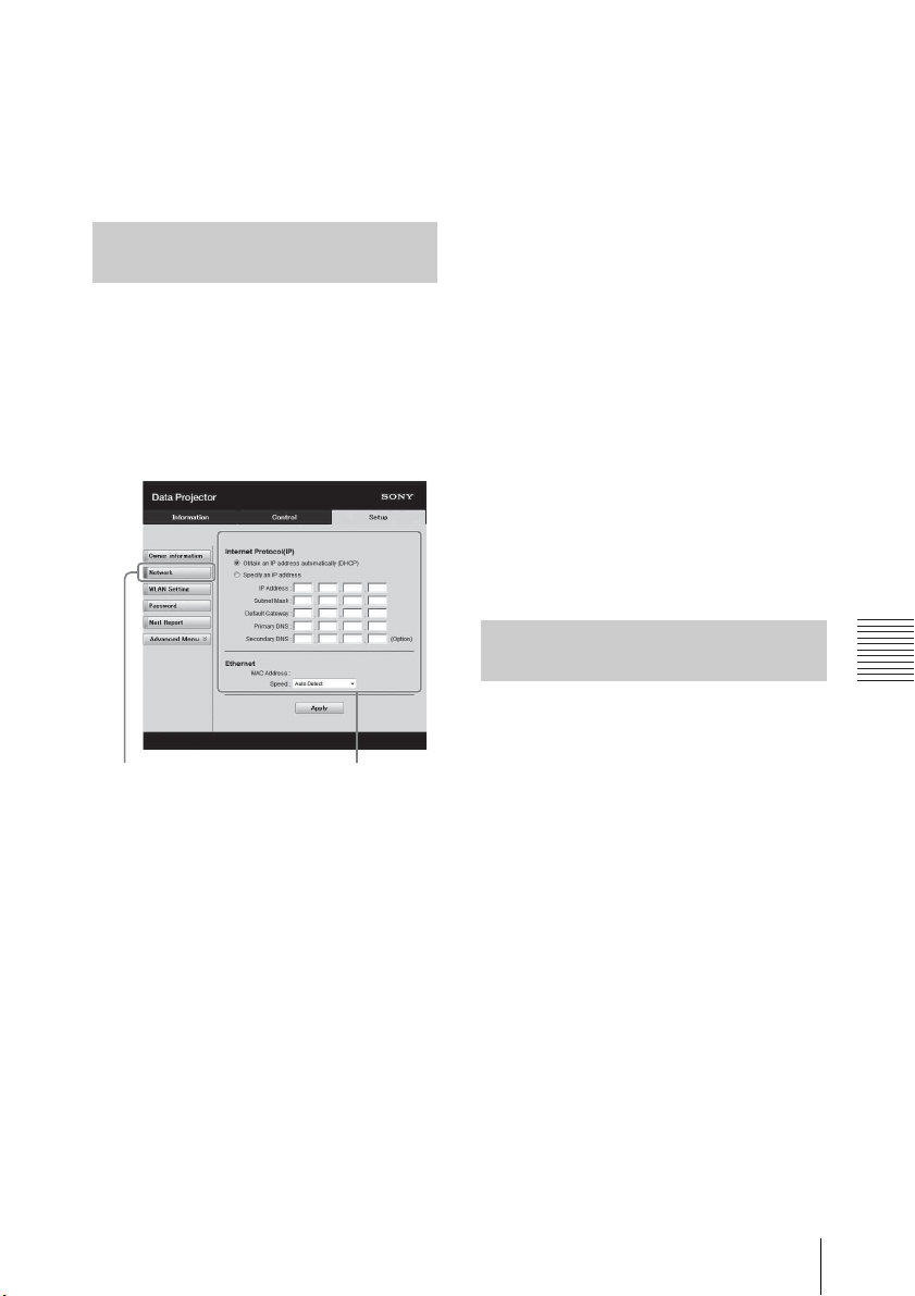
Network
Port25 blocking, which prevents
Network button
LAN Network
setting area
access to the SMTP server.
• You cannot use the following
characters to enter the characters in
t he t ex t b ox : “ ' ”, “ “ ”, “ \ ”, “ & ”, “ < ”,
“>”
Setting the LAN Network of the projector
Set the LAN network function on the
Setup page.
Entered values will not be applied
unless you click on [Apply].
-IP Address:
Input the IP address of the
projector.
-Subnet Mask:
Input the subnet mask of the
projector.
-Default Gateway:
Input the default gateway of the
projector.
-Primary DNS:
Input the primary DNS server of
the projector.
-Secondary DNS:
Input the secondary DNS server
of the projector.
1 Click on [Network] to open the
Network page.
2 Set the items for internet
protocol.
Obtain an IP address
automatically:
Automatically provides the
network settings by a DHCP
server function, such as the
router. The IP Address, Subnet
Mask, Default Gateway, Primary
DNS, and Secondary DNS display
the values provided by a DHCP
server.
Specify an IP address:
Set the network manually.
3 Set the items for Ethenet.
MAC Address:
Displays the MAC address of the
projector.
Speed:
Select the network speed of the
projector.
Setting the WLAN Network of the projector
Set the WLAN network function on the
Setup page.
Entered values will not be applied
unless you click on [Apply].
To use the wireless LAN network, a USB
wireless LAN module IFU-WLM3 (not
supplied) is necessary.
Using Network Features
61
Page 62
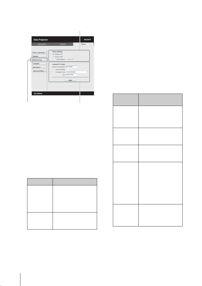
1 Click the [WLAN Setting] to open
WLAN Setting button
the WLAN Setting page.
2
3-(a)
2 Enable or disable the radio wave
output of USB wireless LAN
module.
Wireless ON:
Enables radio wave output of
USB wireless LAN module.
Wireless OFF:
Disables radio wave output of
USB wireless LAN module.
WLAN Network:
Set the modes for USB wireless
LAN module.
Items Descriptions
Access
Point
Client Activates USB
Activates USB
wireless LAN module
as an access point.
Set the items for
WLAN manually.
wireless LAN module
as a client.
3 (a) Input the settings for Access
Point Mode.
When the USB wireless LAN
module is activated as an access
point, set the items for the access
point.
Network Name (SSID):
Input the SSID of the access point
if “WLAN Network” is set to
“Access Point” (page 62).
The factory setting is “VPL + the
MAC address of the LAN.”
Channel Setting:
Select the channel of the access
point if “WLAN Network” is set to
“Access Point” (page 62).
Encryption Type:
Select the security method of the
access point from the followings
if “WLAN Network” is set to
“Access Point” (page 62).
Encyption
Typ e
Open Sets the security
WEP 64bit Sets the security
WEP 128bit Sets the security
MIX (WPAPSK/WPA2PSK (TKIP/
AES))
WPA2PSK(AES)
Descriptions
method of the access
point to open system
authentication.
method of the access
point to WEP (64bit).
method of the access
point to WEP (128bit).
Sets the security
method of the access
point to MIX.
(corresponding to
both WPA-PSK (TKIP/
AES) and WPA2-PSK
(AES) security
methods).
Sets the security
method of the access
point to WPA2-PSK
(AES).
Key:
Input the password for security
method of the access point
according to the selected
encryption type as below;
62
Using Network Features
Page 63
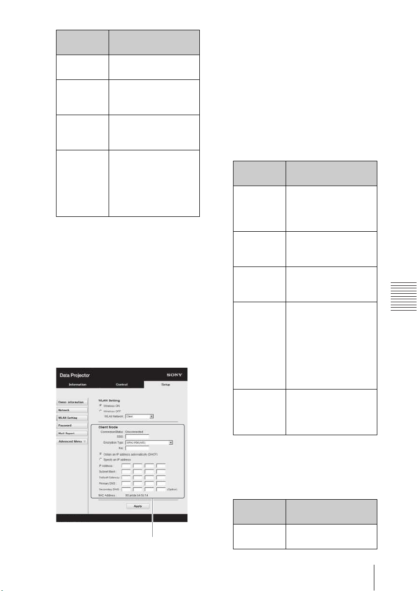
Network
Encyption
3-(b)
Typ e
Open The password cannot
WEP 64bit Input 5 ASCII
WEP 128bit Input 13 ASCII
MIX (WPAPSK/WPA2PSK (TKIP/
AES)) or
WPA2-PSK
(AES)
Password
be input.
characters for a
password.
characters for a
password.
Input 8-63 ASCII
characters for a
password.
The factory setting of the security
method and its password are set as
follows.
Security method: WEP 64bit
Password: sony1
(b) Input the settings for Client
Mode.
When the USB wireless LAN
module is activated as a client, set
the items for the client (set the
items for the access point the
projector tries to connect to).
Connection Status:
Displays the connecting status
between the access point and
projector.
SSID:
Input the SSID of access point the
projector tries to connect to.
Encryption Type:
Select the security method of
access point the projector tries to
connect to from the following
list.
Encyption
Typ e
Open Sets the security
WEP 64bit Sets the security
WEP 128bit Sets the security
MIX (WPAPSK/WPA2PSK (TKIP/
AES))
WPA2-PSK
(AES)
Descriptions
method of the access
point to open system
authentication.
method of the access
point to WEP (64bit).
method of the access
point to WEP (128bit).
Sets the security
method of the access
point to MIX.
(corresponding to
both WPA-PSK (TKIP/
AES) and WPA2-PSK
(AES) security
methods).
Sets the security
method of the access
point to WPA2-PSK
(AES).
Key:
Input the password for security
method of the access point
according to the selected
encryption type as below;
Encyption
Typ e
Open The password cannot
Using Network Features
Password
be input.
63
Page 64
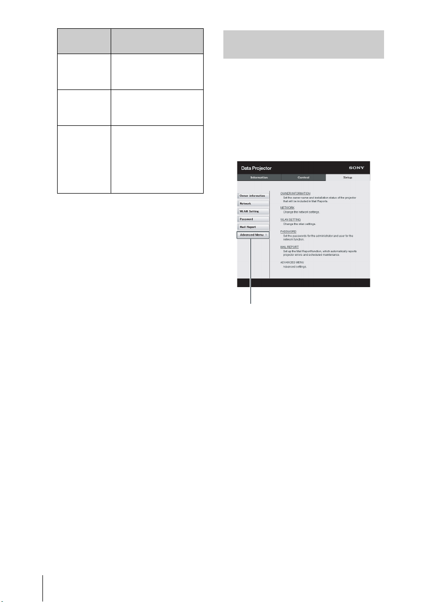
Encyption
Advanced Menu button
Typ e
WEP 64bit Input 5 ASCII
WEP 128bit Input 13 ASCII
MIX (WPAPSK/WPA2PSK (TKIP/
AES)) or
WPA2-PSK
(AES)
Obtain an IP address
automatically:
Automatically provides the
network settings by a DHCP
server function, such as the
router. The IP Address, Subnet
Mask, Default Gateway, Primary
DNS, and Secondary DNS display
the values provided by a DHCP
server.
Specify an IP address:
Set the network manually.
-IP Address:
Input the IP address of the
projector.
-Subnet Mask:
Input the subnet mask of the
projector.
-Default Gateway:
Input the default gateway of the
projector.
-Primary DNS:
Input the primary DNS server of
the projector.
-Secondary DNS:
Input the secondary DNS server
of the projector.
MAC Address:
Displays the MAC address for
USB wireless LAN module.
Password
characters for a
password.
characters for a
password.
Input 8-63 ASCII
characters for a
password.
Setting the Custom Labels for the Input Terminals of the Projector
Change the label names for the input
terminals that will be displayed on the
projected screen on the Set up page.
The entered label names will not be
applied unless you click on [Apply].
1 Click on [Advanced Menu] to
open the Setup page.
2 Click on [Input Label] and open
the Input label setting window.
Clear the check box for the label
that you want to change and input
the label name. You can input up to
20 of the following letters.
Alphabets: "a" to "z", "A" to "Z"
Numbers: "0" to "9"
Characters: ".", "@", "_"
64
Using Network Features
Page 65
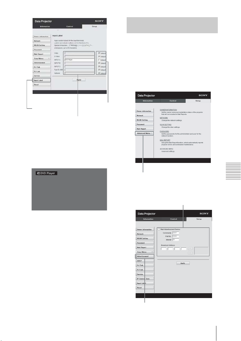
Network
Input Label button
Label name for the
input terminal
Use the
factory
default
setting
Input Terminal Label Display Screen
Setting the Control Protocol of the
Advanced Menu button
Advertisement button
Advertisement
Service setting area
Projector
Change the settings for the control
protocol on the Setup page. Entered
values will not be applied unless you
click on [Apply].
1 Click on [Advanced Menu] to
display the buttons for more
settings.
3 Click on [Apply] to apply the set
label names.
The label name will be reflected on
the screen when the input of the
projector is changed.
2 (a) Set Advertisement.
Using Network Features
65
Page 66
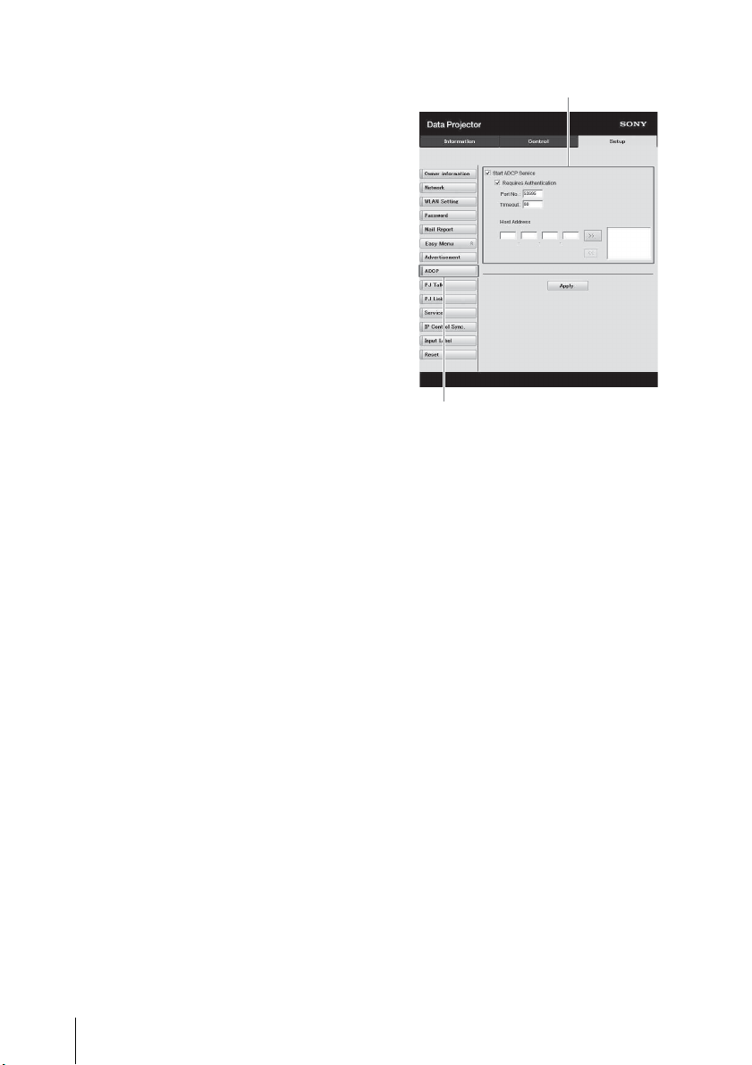
Start Advertisement Service:
ADCP button
ADCP Service setting area
Set Advertisement to enabled or
disabled. Items for
Advertisement are enabled only
when this function is enabled.
The function is disabled at the
factory default.
-Community:
Input the community name for
Advertisement and PJ Talk. If the
community name for
Advertisement is changed, the
one for PJ Talk will also be
changed. Only four
alphanumeric characters can be
input. The factory default setting
is “SONY.” It is recommended
that the community name be
changed from the factory setting
to avoid unnecessary access to
the projector from other
computers.
-Port No.:
Input the transmit port of
Advertisement. The factory
default setting is “53862.”
-Interval:
Input the transmission interval
(seconds) of Advertisement. The
factory default setting is “30.”
-Broadcast Address:
Input the destination of data via
Advertisement. If nothing is
input, the data will be broadcast
in the same subnetwork.
(b) Set ADCP.
Start ADCP Service:
Set ADCP to enabled or disabled.
Items for ADCP are enabled only
when this function is enabled.
The function is enabled at the
factory default.
-Requires Authentication:
Set the authentication for ADCP
to enabled or disabled. The
password is the same as that of
the Web page administrator.
-Port No.:
Input the server port of ADCP.
The factory default setting is
“53595.”
-Timeout:
Input the time (seconds) until
ADCP communication is
terminated in case it is
disconnected. The factory
default setting is “60.”
-Host Address:
Input the IP address that the
ADCP server is allowed to
receive. If no IP address is input,
receiving commands will be
allowed from any IP address.
From the moment the IP address
is input, access will be allowed
66
Using Network Features
Page 67
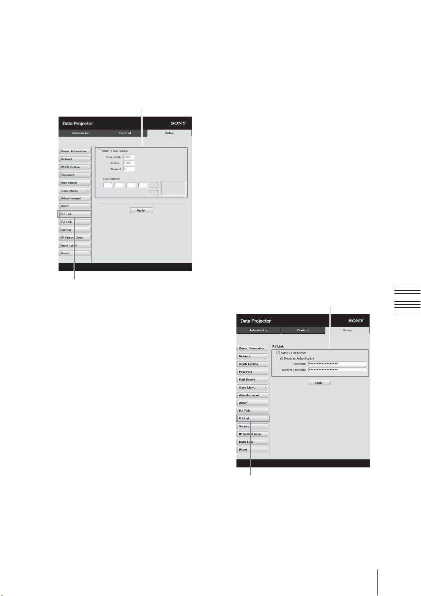
Network
(c) Set PJ Talk.
PJ Talk button
PJ Talk Service setting area
PJ Link button
PJ Link Service setting area
Start PJ Talk Service:
-Community:
only from that input IP address.
For security reasons, it is
recommended to input an IP
address to restrict access.
Set PJ Talk to enabled or
disabled. Items for PJ Talk are
enabled only when this function
is enabled. The function is
disabled at the factory default.
Input the community name of
Advertisement and PJ Talk. If the
community name for PJ Talk is
changed, the one for
Advertisement will also be
changed. Only four
alphanumeric characters can be
input. The factory default setting
is “SONY.” It is recommended
that the community name be
changed from the factory setting
to avoid unnecessary access to
the projector from other
computers.
-Port No.:
Input the server port of PJ Talk.
The factory default setting is
“53484.”
-Timeout:
Input the time (seconds) until PJ
Talk communication is
terminated in the case that it is
disconnected. The factory
default setting is “30.”
-Host Address:
Input the IP address that the PJ
Talk server is allowed to receive.
If no IP address is input, receiving
commands will be allowed from
any IP address. From the
moment the IP address is input,
access will be allowed only from
that input IP address. For security
reasons, it is recommended to
input an IP address to restrict
access.
(d) Set PJ Link.
Start PJ Link Service:
Set PJ Link to enabled or
disabled. Items for PJ Link are
enabled only when this function
is enabled. This function is
disabled at the factory setting.
Using Network Features
67
Page 68
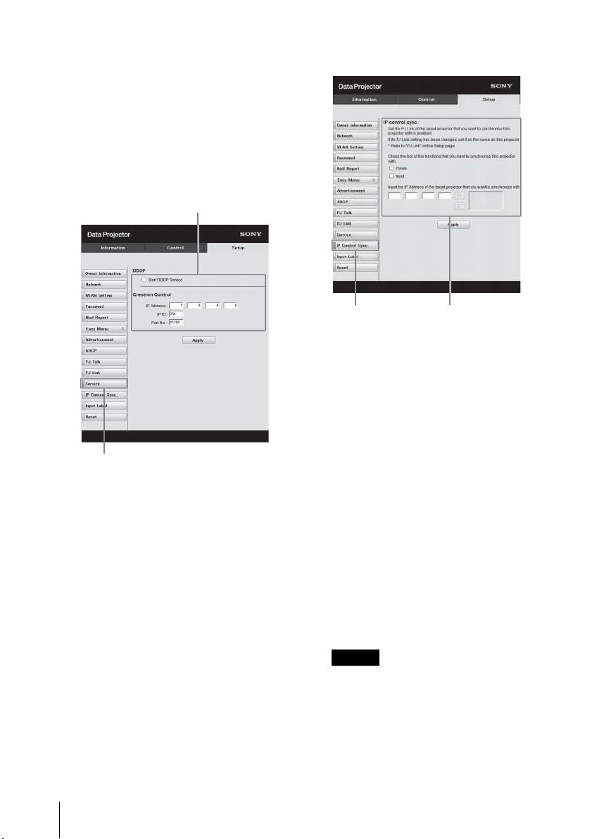
-Requires Authentication:
Notes
Service button
System service setting area
IP Control
Sync. button
IP Control Sync.
setting area
Set the authentication for PJ Link
to enabled or disabled.
-Password:
Input the authentication
password for PJ Link. For the
factory default password, refer to
the PJ Link specifications.
(e) Set the system service.
Start DDDP Service:
Set DDDP to enabled or disabled.
For details, refer to the DDDP
specifications in the reference
from AMX Corporation. The
function is disabled at the factory
default.
Crestron Control:
For details, refer to the
specifications in product
catalogues, etc., from Crestron
Corporation.
-IP Address:
Input the Crestron system server.
-IP ID:
Input the IP ID for the CIP
protocol.
-Port No.:
Input the port number for the CIP
protocol server.
68
Using Network Features
(f) Set the IP Control Sync.
function
*1
-Power:
Set to enabled to change the
power status of the projector
that the unit is trying to
synchronize with to the same
status on the unit when you
turn/off the unit.
-Input:
Set to enabled to change the
input connector of the projector
that the unit is trying to
synchronize with to the same
one on the unit when you
change the input connector on
the unit.
*2
-IP Address:
Input the IP address of the
projector that the unit is trying to
synchronize with.
*1: Enable the PJ Link function of the
projector the unit will synchronize
with, and then set the
authentication and password of
PJ Link in the same way as on the
unit.
*2: The input connectors may not be
changed depending on the
Page 69
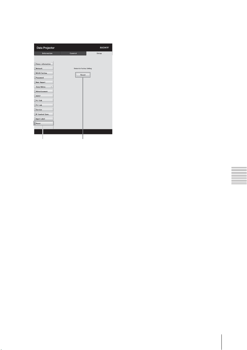
Network
projector the unit is trying to
Reset button
Reset
synchronize with.
(g) Reset the network settings.
Reset:
Reset all Web browser settings to
their factory defaults.
Using Network Features
69
Page 70

Presentation Function via Network
Notes
Using Presentation Function via Network
The Presentation Function via Network enables you to do the following:
• Connect a maximum of eight computers to the projector.
• Project images from a maximum of four computers simultaneously.
• Connecting a USB wireless LAN module (not supplied) to the projector as an
access point, allows the projector to connect to up to seven computers
simultaneously.
Presentation Function via Network requires installation of Projector Station for
Network Presentation. For information on getting and updates of Projector Station
for Network Presentation, visit Sony’s web site:
https://pro.sony/en_GB/support/software/1237495134081
System requirements for using the application are as follows.
OS
Windows XP: Home/Professional
Windows Vista: Home Premium/Business/Ultimate/Enterprise
Windows 7: Home Premium/Professional (Recommended)/Ultimate/Enterprise
Windows 8/8.1
Mac OS X: 10.6.x/10.7.x/10.8.x/10.9.x/10.10.x
CPU
Pentium4 2.8GHz or faster
• To install the application, administrative rights are required.
• If you do not have administrative rights, the application may not run properly.
• If firewall or security software is installed, the application may not run properly.
• Depending on the type of network adapter, the application may not run properly.
• Images may not be projected properly depending on the operating environment
or the application.
70
Using Presentation Function via Network
Page 71
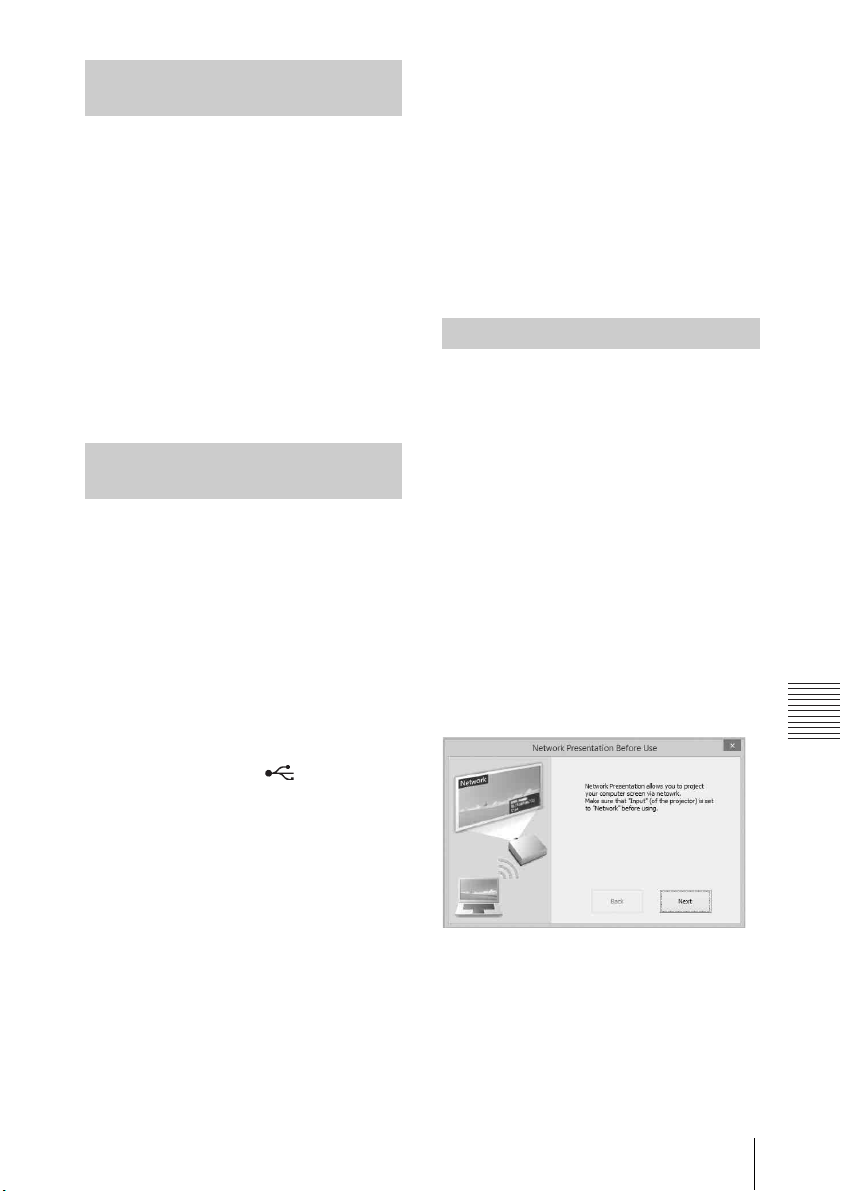
Presentation Function via Network
Installing Projector Station for
Connection guidance window
Network Presentation
1 Close all running applications.
2 Open the downloaded file.
For Windows
Double-click the .exe file. When the
message “User Account Control” is
displayed, click “Allow” or “Yes.”
For Mac
Double-click the .pkg file.
3 Follow the on-screen instructions
to install the software.
Starting Projector Station for Network Presentation
1 Connect the projector to a
network.
For a wired connection, connect
the projector by a LAN cable, then
make the network settings. For
details, see “LAN Settings”
(page 50) or “Setting the LAN
Network of the projector”
(page 61).
For a wireless connection, see “LAN
terminal” (page 27) or “USB
terminal (Type A) ( )” (page 27).
Also check “WLAN Settings”
(page 50).
3 Start Projector Station for
Network Presentation.
For Windows
Select [Start]-[All Programs][Projector Station for Network
Presentation] on the computer.
For Mac
Double-click [Projector Station for
Network Presentation] in
Applications folder.
Projecting an Image
When you start Projector Station for
Network Presentation for the first time
after installing to your computer, the
connection guidance window will be
displayed. This window gives you the
information for the necessary settings
for connection. Be sure to read it
thoroughly. When starting the
application after the first time, the
connection method selection window
will be displayed first. You can check
the connection guidance window
anytime from the connection method
selection window.
For Windows
2 Turn on the projector.
Select “Network” as the input
source (page 33).
1 Select the connection method.
Refer to the network information
on the projected screen of the
projector and select “LAN Mode” or
“AP M o d e .”
Using Presentation Function via Network
71
Page 72
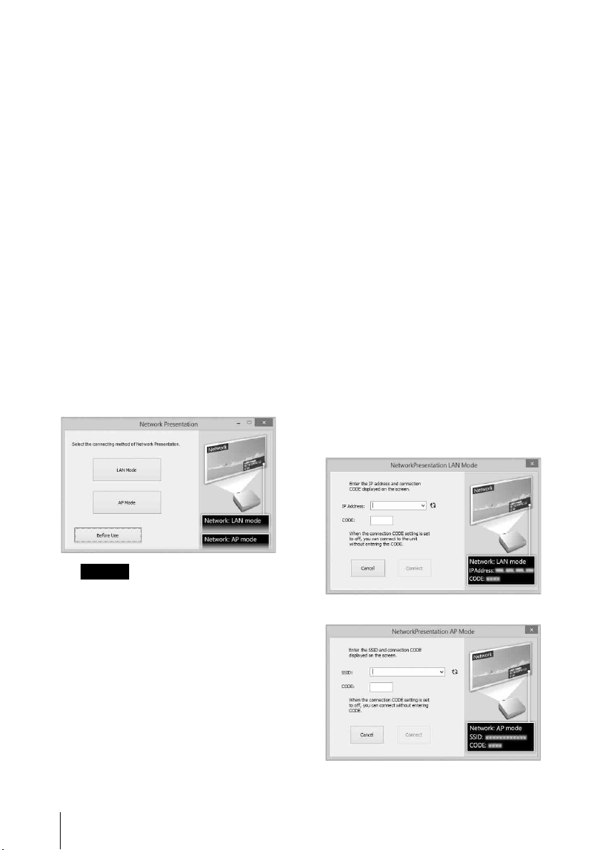
LAN Mode
Note
Connection method selection window
Network Presentation LAN mode
Network Presentation AP mode
Select this mode if “Display
Setting” in “Network
Presentation” is set to “LAN
Mode” on the projector’s menu.
In this mode, the computer
connects to the wired LAN of the
projector or the USB wireless LAN
module of the projector that
operates as a client (“WLAN
Network” page 50).
AP Mode
Select this mode if “Display
Setting” in “Network
Presentation” is set to “AP Mode”
on the projector’s menu. In this
mode, the computer connects to
the USB wireless LAN module of
the projector that operates as an
access point (“WLAN Network”
page 50).
For Windows
“----”, “Connection CODE”
(page 50) is set to “Off.” The
computer can connect without
inputting “CODE”.
b) For AP Mode
Refer to the network information
on the projected screen of the
projector that you want the
computer connect to, and input
the SSID and the Connection
CODE. If “CODE” is
“----”, “Connection CODE” is set
to “Off.” The computer can
connect without inputting
“CODE”. If the wireless password
is set for the SSID (“Setting the
WLAN Network of the projector”
on page 61), the wireless
password input window will be
displayed while the computer is
trying to connect. Input the
password to connect. To prevent
information leaks, the wireless
password is not displayed on the
projected screen.
The appearance of the application on
the screen is subject to change
without notice.
2 Set the projector an image will be
projected to.
72
a) For LAN Mode
Refer to the network information
on the projected screen of the
projector that you want the
computer connect to, and input
the IP address and the
Connection CODE. If “CODE” is
Using Presentation Function via Network
Page 73
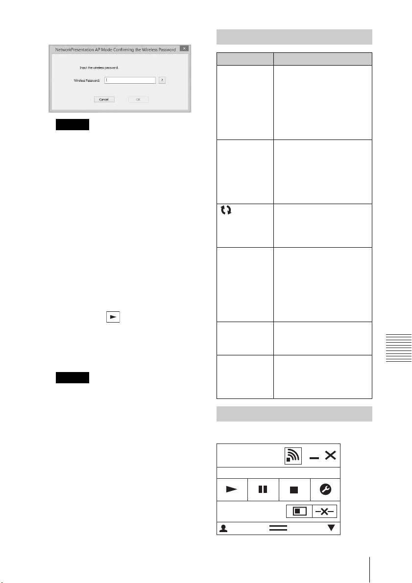
Presentation Function via Network
Notes
• When a projector is connected to a
Notes
Wireless password input window
Network
Presentation
User 000001
CODE: 1234
8
network via a wireless connection,
if the “SSID” is changed from the
factory default, it may not be
found.
• When a projector is connected to a
network via a wired connection,
depending on the network
environment, it may not be found.
3 Click “Connect”.
When you click the “Connect”
button, a controller will be
displayed on the screen of the
computer and the computer starts
projecting an image (page 73). If
another user is projecting an
image, click to start projecting.
If no users are projecting an image,
the controller appears on the
screen and starts projecting an
image.
• Display related settings (such as
your computer's resolution)
change when the application is
started.
• If “Input” is set to other than
“Network” (page 33), the image
will not start being projected even
after you press the “Connect”
button. If you want to project the
image, select “Network” to change
the display status.
Connection Settings
Item Item descriptions
IP Address Input the IP Address.
List the IP addresses of
the projectors on the
network and IP
addresses of projectors
connected so far, as
candidates.
SSID Input SSID.
List the peripheral SSIDs
and SSIDs of projectors
connected to the
computer so far, as
candidates.
Update
button
Wireless
Password
CODE Input the Connection
Connect Connect to the projector
Search the network
again and update the
candidate list of the
projectors.
Input the wireless
password of the SSID. If
open system
authentication is used,
input of the wireless
password is
unnecessary.
CODE displayed on the
screen of the projector.
that is set in the items
above and start to
project an image.
Using the Controller
For Windows
Using Presentation Function via Network
73
Page 74
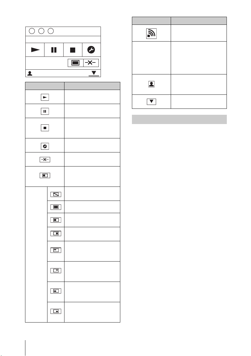
For Mac
CODE: 1234
User64
1
Items Functions
Start projecting an
image.
Pause projecting an
image.
Stop projecting an
image (screen turns
black).
Change the
application settings.
Disconnect from the
projector.
Select a projection
method then start
projecting an image.
Projection
method
Not projecting an
image.
Project in full screen.
Project in the left half
of the screen.
Project in the right
half of the screen.
Project in the upper
left quadrant of the
screen.
Project in the upper
right quadrant of the
screen.
Project in the lower
left quadrant of the
screen.
Project in the lower
right quadrant of the
screen.
Items Functions
Display the strength
of the wireless signal.
Display the
Connection CODE of
CODE
the projector that is
connected to the
computer.
Display the number of
users connected to
the projector.
Display the users’
status.
One-Click projecting function
Projector Station for Network
Presentation allows you to create a
shortcut that registers the connection
setting.
By starting the application with the
shortcut, you can project the image to
the registered projector.
1 Create a file.
For Windows
Create a shortcut to the
NetworkPresentation. exe. Copy the
shortcut to the Projector Station for
Network Presentatio n, or right-click
the NetworkPresentation.exe in the
installed folder to select “Create
shortcut” from the pop up menu.
For Mac
Create a text file with any name
with a text editor. Set the format to
“Plain Text.”
2 Register the connection setting.
For Windows
Register the settings. Right-click
the created shortcut and select
“Properties” from the pop up
menu.
74
Using Presentation Function via Network
Page 75
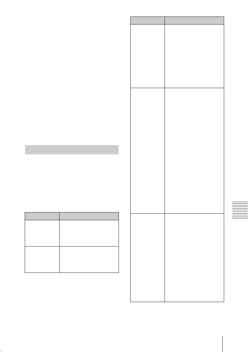
Presentation Function via Network
Input the settings of the projector
that you want the computer to
connect to in “Target” from the
“Shortcut” tab and save. For the
format for the settings, refer to the
command formats in the option
format.
For Mac
Input the settings of the projector
that you want the computer to
connect to in the created text file
and save.
Refer to the command format in
the option format to input settings.
Right-click the created text file and
select “Get Info” from the context
menu. Change the extension of the
filename that is displayed on
“Name & Extension” to “.npr”.
Option format
Command format
For LAN Mode
- connect [IP address]:[CODE]:
[Display Setting]
For AP Mode
- wifi [SSID]:[Wireless password]:
[CODE]:[Display Setting]
Item Description
IP address Assign the IP address of
the projector that you
want the computer to
connect to.
SSID Assign the SSID of the
projector that you want
the computer to
connect to.
Item Description
Wireless
password
CODE Assign the settings of
Display
setting
Assign the wireless
password for the SSID. If
the security method is
Open System
authentication, input
“open.”
If the USB LAN wireless
module setting is set to
“Access Point,” input
*1
“auto.”
the Connection CODE of
the projector.
on: Displays the
dialogues for inputting
the Connection CODE
when the computer is
trying to connect to the
projector.
off: Does not display
the dialogues for
inputting the
Connection CODE when
the computer is trying
to connect to the
projector. If “Connection
CODE” of the projector
is set to “On”, an
authentication error
occurs.
Sets the status for when
the projector starts
projecting an image.
0:Does not display an
image when the
computer starts
projecting an image.
You need to start
projecting an image
with the controller.
1:Displays an image
when the computer
starts projecting an image.
*1: “Access Point” can be selected on the
compatible models only. This model
is not compatible for the settings of
“Access Point.”
Using Presentation Function via Network
75
Page 76
Command Examples
Example 1)
If the settings of the projector that you
want the computer to connect to are
set as below and you want to display
an image when the computer starts
connecting to it
Network:LAN Mode
IP address:192.168.1.187
Connection CODE: On
For Windows
C:\Program Files (x86)\Sony\Projector
Station for Network
Presentation\Network
Presentation.exe -connect
192.168.1.187:on:1
For Mac
-connect 192.168.1.187:on:1
Example 2)
If the settings of the projector that you
want the computer to connect to are
set as below and you want to display
an image when the computer starts
connecting to it
Network: AP Mode
SSID: VPL012ABC
Wireless password: sony1
Connection CODE: Off
For Windows
C:\Program Files (x86)\Sony\Projector
Station for Network
Presentation\Network
Presentation.exe -wifi VPL012ABC:
sony1:off:1
For Mac
-wifi VPL012ABC:sony1:off:1
Use Projector Station for Network Presentation without installing it to the computer.
Projector Station for Network
Presentation also has a portable
version that can be used with external
media, such as a USB mass storage
device. Although some functions are
limited, you can put and carry the
Projector Station for Network
Presentation in the external media,
and use it on other computers.
1 Close all running applications.
2 Open the downloaded file.
For Windows
Double-click the
“PJS_NetworkPresentationP_XXX
.exe” file for portable. If the User
Account Control window is
displayed, click “Allow” or “Yes.”
For Mac
Double-click the
“PJS_NetworkPresentationP_XXX
.pkg” file.
3 Follow the instructions in the
wizards to install the application
software.
4 Start the Projector Station for
Network Presentation.
For Windows
Double-click the shortcut icon of
Projector Station for Network
Presentation that is created in
the folder in which the
application is installed.
For Mac
Double click “Projector Station
for Network Presentation” in the
folder in which the application is
installed.
76
Using Presentation Function via Network
Page 77

Presentation Function via Network
Notes
• You can use this application only on
the OS that supports this
application.
• Make sure Projector Station for
Network Presentation is not
operating before installing the
application.
• Make sure the external media that
the application will be installed to
has access rights and all files in the
external media are closed.
Using Presentation Function via Network
77
Page 78

Error code list of Projector Station for Projector Station for Network Presentation
Error code Meaning/Measure Page
NPR-E1701 Failed while opening the WLAN device of the
computer.
Check that the WLAN function of the computer
operates normally.
NPR-E1702 Failed while scanning the access point.
Check that the WLAN function of the computer
operates normally.
NPR-E1703 Failed while getting information of the access point.
Check the WLAN function of the computer, and if
multiple WLAN networks exist.
NPR-E1704 Cannot find the access point.
Check if devices are connected correctly, the input SSID
is correct and the projector is turned on.
NPR-E1705 Tried but failed while connecting using WEP64 bit or
WEP128 bit. Check that the security setting of the
WLAN function of the projector is correct.
NPR-E1706 Tried but failed while connecting using MIX (WPAPSK/
WPA2-PSK (TKIP/AES)), WPA2-PSK (AES). Check that
the security setting of the WLAN function of the
projector is correct.
NPR-E1707 A security setting other than WEP 64bit, WEP 128bit,
MIX (WPAPSK/WPA2-PSK (TKIP/AES)), WPA2-PSK (AES)
is applied. Check that the input SSID and the security
setting of the WLAN function of the projector are
correct.
NPR-E1708 Failed to acquire the network profile. Check if the
WLAN function of the computer operates normally.
NPR-E1709 Succeeded in authenticating the access point, but
failed while associating. Check if multiple WLAN
networks exist, or if the status of the projector
changed while the computer tried to connect to the
projector.
NPR-E1802 Failed while getting the IP address after connecting to
the access point. Check the input SSID, security
password and the setting of the security software of
the computer.
NPR-E1803 Succeed in connecting to the access point, but failed
while getting the information. Check the setting of the
security software of the computer.
61
61
27,61
33,75
75
75
27,75
–
–
–
–
78
Using Presentation Function via Network
Page 79

Presentation Function via Network
Error code Meaning/Measure Page
NPR-E1804 Connected to a different SSID (access point) from the
one you assigned.
Start from the connection setting again.
NPR-E2101 Cannot receive a response from the projector.The
response may be blocked or the network may have
been disconnected from the projector while
communicating. Check the setting of the security
software of the computer, the power status and the
network composition of the projector.
73
–
Using Presentation Function via Network
79
Page 80

Playing Video and Audio using USB Connection
Notes
Playing Video and Audio using USB Connection
You can also play video and audio simply by connecting the projector and
computer with a USB A-B cable (not supplied).
Playing video and audio using USB connection requires to start USB Display.
System requirements for using the application are as follows.
OS
Windows XP: Home/Professional
Windows Vista: Home Premium/Business/Ultimate/Enterprise
Windows 7: Home Premium/Professional (Recommended)/Ultimate/Enterprise
Windows 8/8.1
Mac OS X: 10.6.x/10.7.x/10.8.x/10.9.x/10.10.x
CPU
Pentium4 2.8GHz or faster
Starting USB Display
1 Connecting the projector and your computer with a USB A-B cable (not
supplied) (page 26).
2 Turn on the projector.
Select “Type B USB” as the input source (page 33). After a short time, the
projector is recognized as a CD-ROM drive in the computer.
3 Open “USB Display” in the CD-ROM drive.
• The resolution of your computer changes when the application is started.
• Depending of the computer’s setting, the application may start automatically.
• When you are finished using the projector, you can simply disconnect the USB
cable without using the Safely Remove Hardware option.
• Movie player (Media Player, etc.) images may not be projected properly.
80
Playing Video and Audio using USB Connection
Page 81
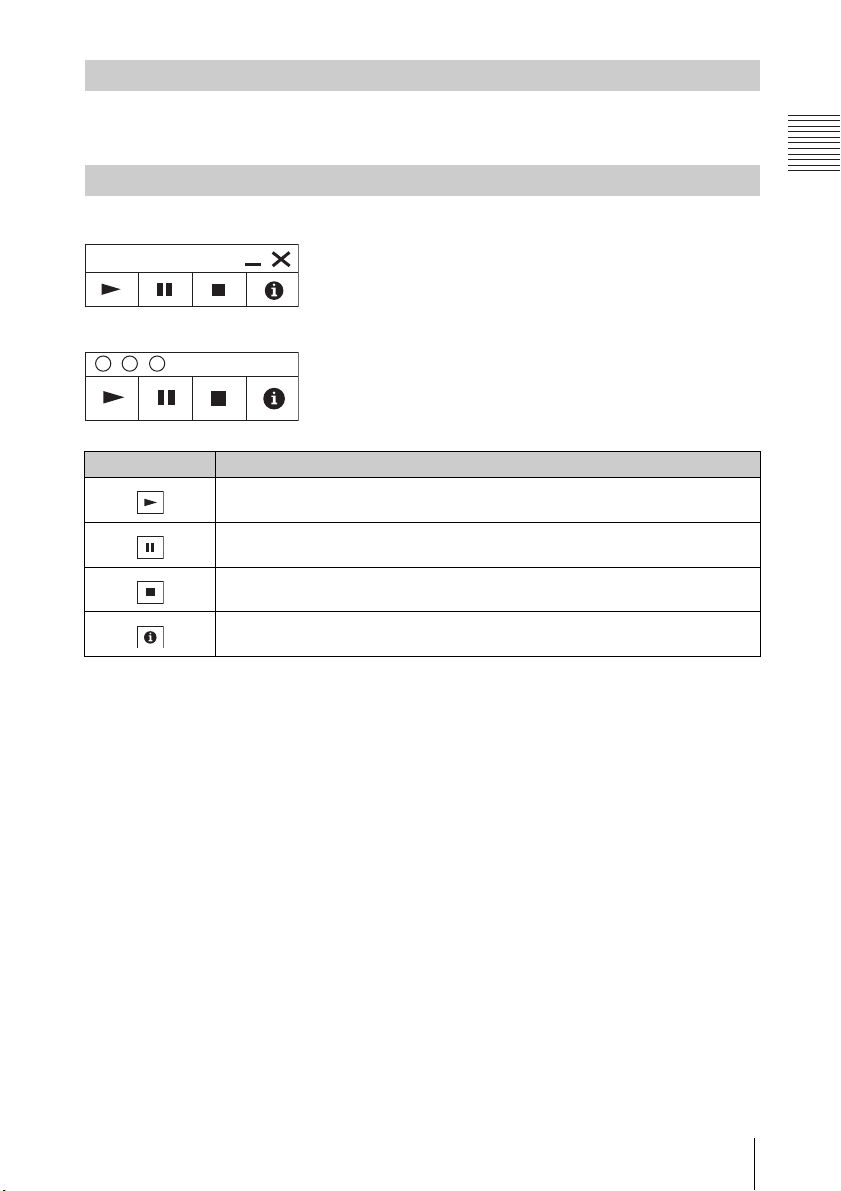
Playing Video and Audio using USB Connection
Playing Video and Audio
USB Display
After starting USB Display, the controller appears on the screen, and projection
playback starts automatically.
Using the Controller
For Windows
For Mac
Items Functions
Start audio/video playback.
Pause audio/video playback.
Stop audio/video playback (the screen turns black).
Display information about USB Display.
Playing Video and Audio using USB Connection
81
Page 82
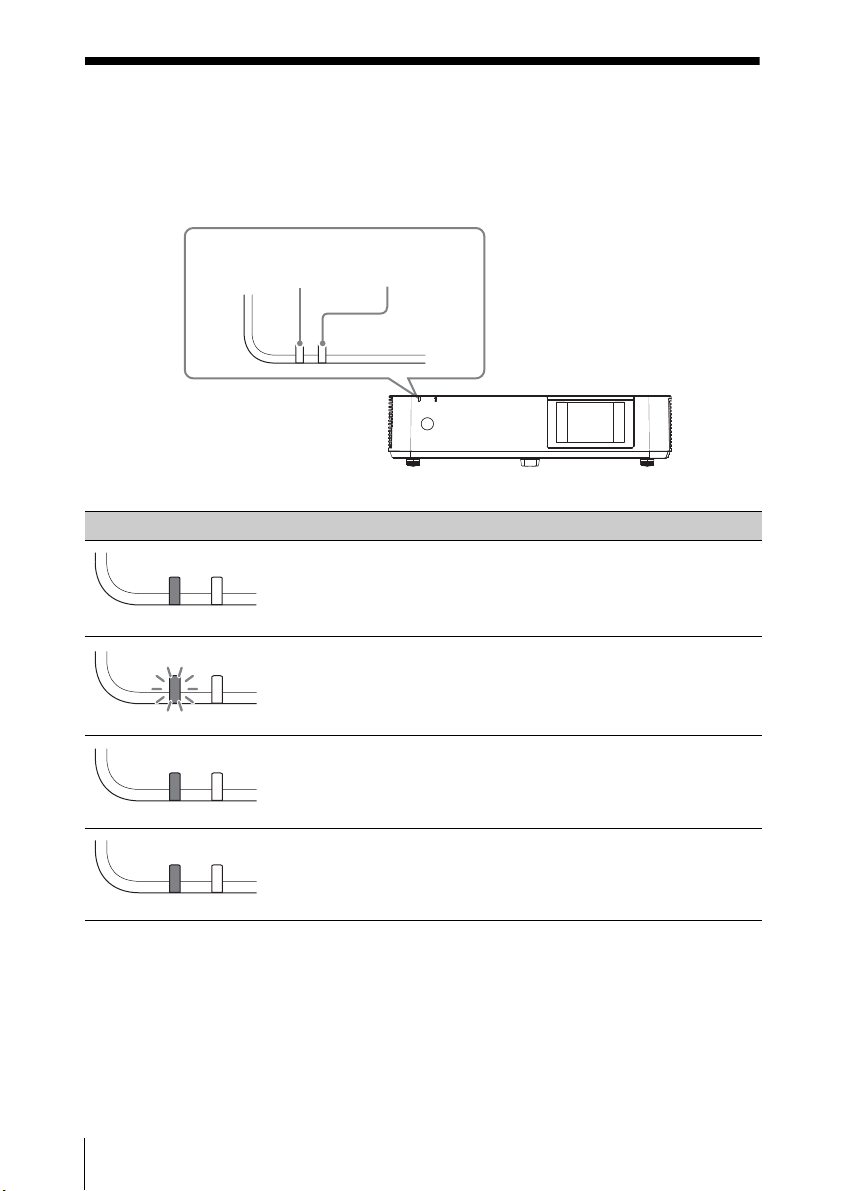
Others
ON/STANDBY
indicator
WARNING
indicator
(Off)(Lights in red)
(Off)(Flashes in green)
(Off)(Lights in green)
(Off)
(Lights in orange)
Indicators
You can check the projector status or abnormality by checking the lighting/
flashing status of the ON/STANDBY indicator and WARNING indicator on the front.
If the indicators flash in red, address the problem in accordance with “Warning
indicators and remedies” (page 83).
Operating status indication
Indicator status Operating status Meaning
Standby The power is supplied to the projector and
the projector is in a standby mode according
to the setting.
82
Indicators
Warm-up The projector is warming up after it is turned
on.
Power on The projector is ready for projection.
Other standby
status
The projector is in With No Input (Light
Cutoff), Quick Reboot standby mode, or the
Speaker Setting is set to “Always On.”
Page 83
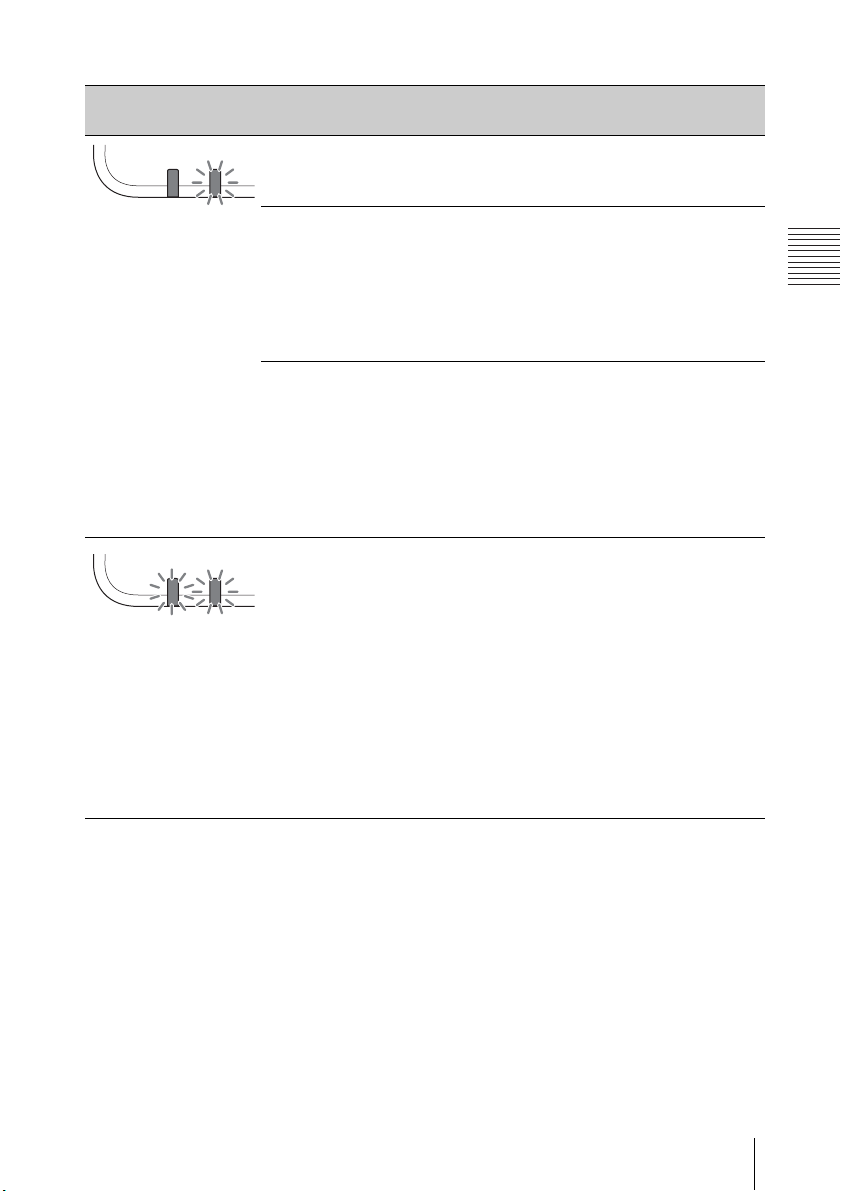
Others
Warning indicators and remedies
(Flashes
in red)
(Lights
in red)
(Flashes
in red)
(Flashes
in red)
Both indicators
flash
Indicator status
The number of
flashes
Meaning Remedies
Twice The air filter is not
installed securely.
Check how the air filter is
attached and install
securely.
Three times The light source
does not light
properly.
Unplug the AC power cord
and make sure the ON/
STANDBY indicator turns
off, then plug the AC
power cord into the wall
outlet and turn on the
projector.
Six times A strong shock to
the projector is
detected.
If there is no visible
abnormality, unplug the
AC power cord and make
sure the ON/STANDBY
indicator turns off, then
plug the AC power cord
into the wall outlet and
turn on the projector.
Twice The temperature
in the projector is
abnormal.
Check if the air filter is
clogged, then clean or
replace it (page 89).
Check if the ventilation
holes (intake/exhaust)
are not blocked by the
wall or an object and
secure a sufficient gap.
Check the ambient
temperature and use
the projector within the
range of operating
temperature.
If the indicators flash in a manner other than described above, unplug the AC
power cord and make sure the ON/STANDBY indicator turns off, then plug the AC
power cord into the wall outlet and turn on the projector.
If the problem still persists, consult with qualified Sony personnel.
Indicators
83
Page 84

Messages List
When any of the messages listed below appears on the projected image, address
the problem in accordance with the table below.
Messages Meaning/Remedy Page
Clean the filter.
Projector
temperature is high.
Switching to High
Altitude Mode.
Temperature in the projector has increased.
As a countermeasure against use at an altitude of
1,500 m or higher, set “High Altitude Mode” to “On.”
If you are not using the projector at a high altitude,
perform the remedies below and set “High Altitude
Mode” to “Off.”
Check that the air filter is clogged, then clean or
replace it.
Check that the ventilation holes (intake/exhaust)
are not blocked by a wall or an object and secure a
sufficient gap.
Check the ambient temperature and use the
projector within the range of operating
temperature.
Clean the filter.
Projector
temperature is high.
The light will turn off
in 1 minute.
Temperature in the projector has increased.
Perform the remedies below.
Check that the air filter is clogged, then clean or
replace it.
Check that the ventilation holes (intake/exhaust)
are not blocked by a wall or an object and secure a
sufficient gap.
Check the ambient temperature and use the
projector within the range of operating
temperature.
“High Altitude Mode” on this projector is set to
“On.” Set the setting that suits the operating
environment.
Frequency is out of
range!
Change the output setting of the connected
equipment to one for signals supported by the
projector.
Please check Input-A
Signal Sel.
Set “Input-A Signal Sel.” to “Auto” or select the input
signal type to suit to the input signal.
Not applicable! Invalid key was pressed. 22
The control keys are
“Control Key Lock” is set to “On.” 49
locked!
Light Dimming Reduces light output when “With Static Signal” is
set. When any change in signal is detected, or an
operation (remote control or control panel) is
performed, normal brightness is restored.
20, 89
20, 89
96
51
52
84
Messages List
Page 85

Others
Messages Meaning/Remedy Page
Filter cleaning will
start.
Filter cleaning
completed.
Unsupported USB
device.
Unsupported USB
hub.
Please check
HDBaseT Settings.
The filter will be automatically cleaned after the
projector is turned off.
The filter was automatically cleaned when the
projector was turned on.
Connect the designated USB device (USB wireless
LAN module IFU-WLM3 (not supplied)).
The projector does not support USB hubs. Connect
the designated USB device (USB wireless LAN
module IFU-WLM3 (not supplied)).
Set “HDBaseT/LAN Port” depending on the
HDBaseT/LAN connection.
54
54
27
27
50
Messages List
85
Page 86
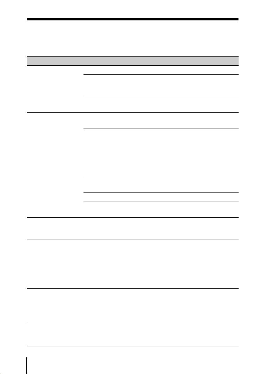
Troubleshooting
Before asking to have the projector repaired, try to diagnose the problem,
following the instructions below.
Symptoms Remedy Page
The power is not
turned on.
No image. Check if the connecting cable is connected to
The color of image
has changed.
Images that are not
intended are output.
The application “USB
Display” or “Projector
Station for Network
Presentation” does
not start.
The computer cannot
connect to the
projector.
Check if the AC power cord is firmly connected. –
When the “Control Key Lock” is set to “On,” you
cannot turn on the projector using the / key on
the projector.
Check how the air filter is attached and install it
securely.
external equipment firmly.
Check if the computer signal is set for output to an
external monitor. If you set your computer, such as a
notebook computer, to output the signal to both
your computer’s display and an external monitor,
the picture of the external monitor may not appear
properly. Set your computer to output the signal to
only an external monitor.
Check if the application “USB Display” or “Projector
Station for Network Presentation” is running.
Check if the input source is correctly selected. 33
Check if the picture is muted by pressing the BLANK
key.
The color calibration may have been performed. To
restore the color or factory setting, perform “Return”
or “Reset” in “Color Calibration.”
The color calibration may be being performed.
During this mode, the pattern for color calibration is
displayed automatically. Since the pattern turns off
automatically after this mode ends, please wait for a
while. If you press the / button on the unit or
remote control, the pattern also turns off. At the
same time, this mode also ends.
Check if the computer connected to the projector
meets the system requirement for the applications.
Check “LAN Settings” of the projector.
Check the condition of the wireless connection.
70, 80
22, 47
70, 80
49
89
25
34
22
47
50
86
Troub lesho oting
Page 87
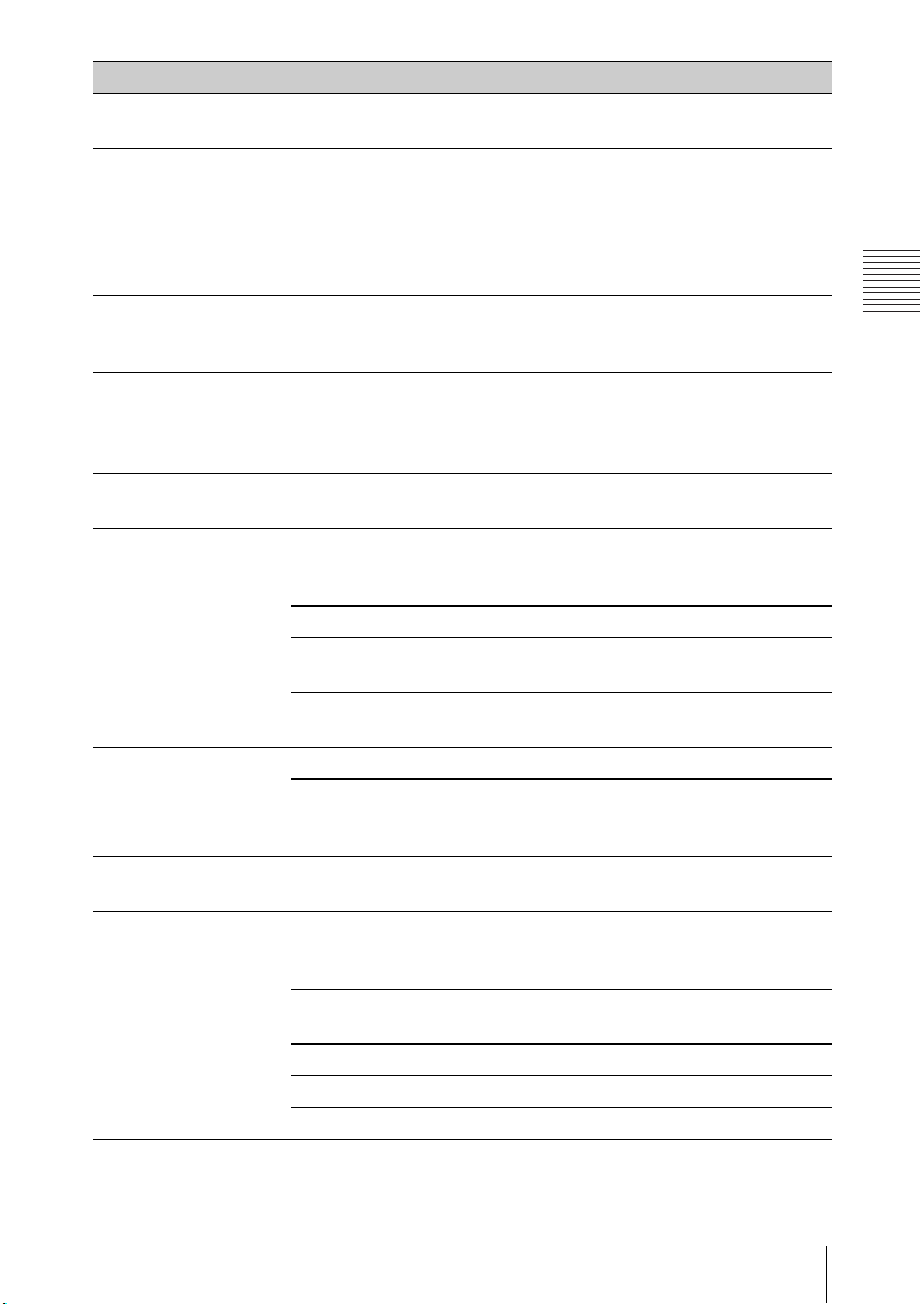
Others
Symptoms Remedy Page
On-screen display
does not appear.
The aspect ratio of
the display is not
right/the image is
displayed smaller /a
portion of image
does not appear.
The image is a
trapezoid.
Edges of the image
are cut off or dark.
The image is
distorted.
The image is dark/
too bright.
The image is not
clear.
The image is noisy. Check if the connecting cable is connected to the
No sound. Check that the connecting cables between the
The on-screen display does not appear when
“Status” in the Operation menu is set to “Off.”
The image may not display correctly because the
input signal cannot be judged correctly. In this case,
set “Aspect” manually.
The images become trapezoidal because of the
projection angle. In this case, you can correct the
trapezoidal distortion, using a Keystone feature.
If you use the lens shift function with a setting
outside the recommended range, edges of the
image may be cut off or appear dark. Use a setting
within the normal range for the lens shift function.
Warping is set.
Disable the warp correction feature.
The settings for “Brightness,” “Contrast,” and “Light
Output Mode” affect brightness of the image. Check
if the value is appropriate.
“With Static Signal” is set to “On.” 52
When video signal is not input, the light is dimmed
to reduce power consumption.
When the temperature around the unit is high, the
brightness will be reduced to protect the unit.
Check if the projector is in focus. 34
The picture will not be clear if condensation has
accumulated on the lens. In this case, let the
projector sit for about two hours with the power on.
external equipment properly.
projector and external video or audio equipment are
securely connected.
Check if the external audio equipment is set
properly.
Audio is not output if “Speaker” is set to “Off.” 47
Audio is not output if audio muting is activated. 22
Check if the volume is not set to minimum. 22, 47
49
22, 44,
46
22, 36,
54
97
38, 54
42, 51
51
–
–
25
25
–
Troubleshooting
87
Page 88

Symptoms Remedy Page
The remote
commander does not
work.
The fan is noisy. The sound from the fan is often greater than normal
Check if the batteries are installed correctly. –
Check if the batteries are not exhausted. –
Check the setting for “IR Receiver.” 49
51, 54
to cool the light source in the following cases.
When “Light Output Mode” is set to “Standard”.
The projector is in at high altitude (“High Altitude
Mode” is set to “On”)
Temperature is very high.
Check that the air filter is clogged, then clean or
20
replace it.
Check that the ventilation holes (intake/exhaust)
are not blocked by a wall or an object and secure a
sufficient gap.
The image is
distorted by the
HDBaseT connection.
The image is not
projected properly
Confirm whether the unit’s AC power cord is
grounded.
Use the STP (Shielded Twisted Pair) type LAN cable.
Change the input terminal to project the image
properly.
–
–
when the projector is
connected via the
HDBaseT terminal
and the cables are
inserted or removed
from other terminals.
88
Troub lesho oting
Page 89
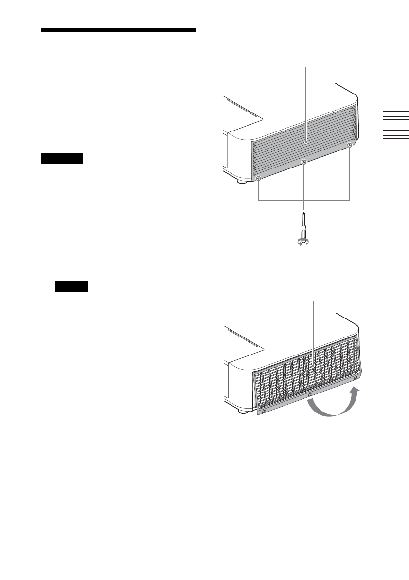
Others
Caution
Note
2 Loosen the screws (three) on the
Side cover
Side cover
Cleaning the Air Filter
When the message on cleaning the air
filter is displayed on the projected
image, clean the air filter (page 84).
If the dust cannot be removed from
the air filter even after cleaning,
replace the air filter with a new one.
For details on a new air filter, consult
with qualified Sony personnel.
If you keep using the projector even
after the message is displayed, dust
may accumulate, clogging it. As a
result, the temperature may rise
inside the unit, leading to a possible
malfunction or fire.
side cover.
1 Turn off the projector, and
disconnect the AC power cord
from the AC outlet.
If you remove the side cover while
the AC power cord is not removed
from the AC outlet and power is not
turned off, you may touch the fan
inside the unit, resulting in injury.
3 Lift up the bottom of the side
cover to remove.
Cleaning the Air Filter
89
Page 90
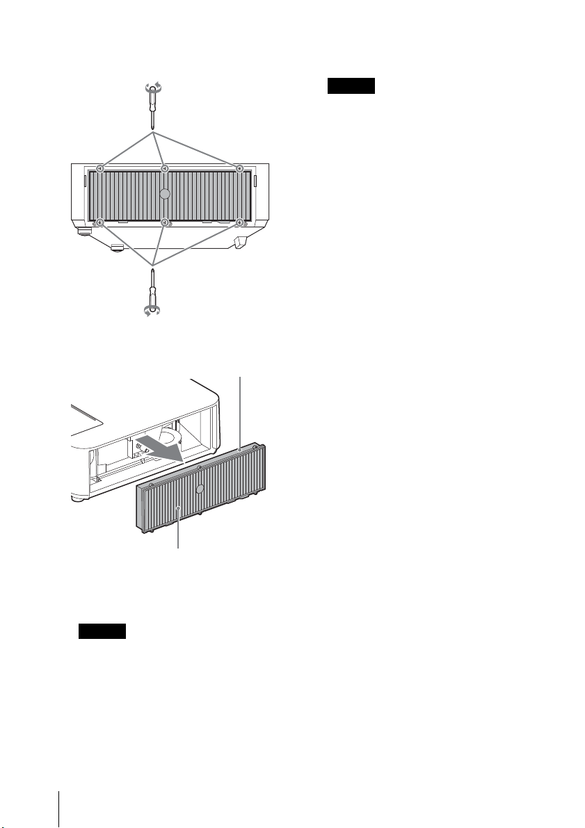
4 Loosen the screws (six) on the air
Note
Notes
Air filter
Cushion
filter.
5 Remove the air filter.
7 Replace the air filter and attach
the side cover.
• Be sure to attach the air filter
firmly; the power cannot be turned
on if it is not attached securely.
• Be sure to attach the side cover
firmly. Incorrect attachment of the
cover may cause a malfunction.
6 Clean the air filter with a vacuum
cleaner.
Before attaching the air filter to the
unit, make sure that the cushion on
the frame of the air filter is not
dislocated or loose.
90
Cleaning the Air Filter
Page 91
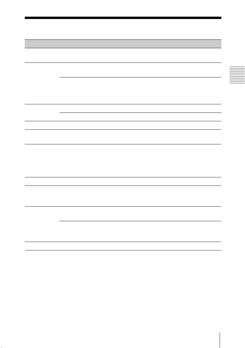
Others
Specifications
Items Descriptions
Projection
system
Display
device
Projection
lens
Light source Laser diode
Projected
image size
Luminous
flux
(Brightness)
Speaker 16 W × 1 (monaural)
Applicable
scanning
frequency
Resolution
Color system NTSC3.58, PAL, SECAM, NTSC4.43, PAL-M , PAL- N, PAL60
Effective
display size
Effective
picture
elements
Focus Manual
Zoom Manual (1.45 times)
*1
*1
Computer
signal input
Video signal
input
3 LCD system
0.76-inch (19.3 mm), 3 plate, Aspect ratio 16:10
VPL-PHZ11:
6,912,000 pixels (1,920 × 1,200 pixels, 3 plate panels)
VPL-PWZ11:
3,072,000 pixels (1,280 × 800 pixels, 3 plate panels)
40 inches to 300 inches (1.02 m to 7.62 m)
5,000 lm
(when “Light Output Mode” is set to “Standard”)
4,500 lm
(when “Light Output Mode” is set to “Standard”,
"Constant Brightness" is set to "On.")
Horizontal: 15 kHz to 92 kHz, Vertical: 48 Hz to 92 Hz
Maximum display resolution: 1,920 × 1,200 pixels
NTSC, PAL, SECAM, 480/60i, 576/50i, 480/60p,
576/50p, 720/60p, 720/50p, 1080/60i, 1080/50i,
1080/24p
Specifications
91
Page 92

Items Descriptions
INPUT
OUTPUT
(Computer/
video)
Other
terminals
Operating
temperature/
Operating
humidity
Storage
temperature/
Storage
humidity
Power
requirements
Power
consumption
INPUT A RGB/YPBPR input terminal: Mini D-sub 15-pin
female, G with sync/Y: 1 Vp-p ± 2 dB, sync negative,
75 ohms terminated, RGB/PBPR: 0.7 Vp-p ± 2 dB,
75 ohms terminated, Sync signal: TTL level high
impedance, positive/negative
Audio input terminal: Stereo mini jack, rated input
500 mVrms, input impedance more than 47 kohms
INPUT B/
INPUT C
VIDEO IN Video input terminal: Phono jack, 1 Vp-p ± 2 dB, sync
OUTPUT Audio output terminal: Stereo mini jack, stereo, 1
INPUT D HDBaseT/LAN Port: RJ45, HDBaseT/
AC 100 V to
120 V
AC 220 V to
240 V
HDMI input terminal: HDMI 19-pin, HDCP support,
Audio input terminal: HDMI audio support
negative, 75 ohmes terminated
Audio input terminal: Shared with INPUT A
Vrms (maximum volume, when inputting 500
mVrms), output impedance 5 kohms
RS-232C terminal: D-Sub 9 pin male
100BASE-TX
HDBaseT transmittable signal: HDMI (Video, Audio),
RS-232C, Ethernet
HDBaseT LAN cable: STP type (CAT5e or higher,
straight, not supplied), Maximum length: 100 m
USB terminal: Type A
USB terminal: Type B
0 °C to 40 °C (32 °F to 104 °F)/20% to 80% (no
condensation)
–10 °C to +60 °C (14 °F to 140 °F)/20% to 80% (no
condensation)
VPL-PHZ11:
100 V to 240 V AC, 4.3 A-1.7 A, 50/60 Hz
VPL-PWZ11:
100 V to 240 V AC, 4.0 A-1.6 A, 50/60 Hz
VPL-PHZ11: 424 W
VPL-PWZ11: 399 W
VPL-PHZ11: 403 W
VPL-PWZ11: 377 W
92
Specifications
Page 93
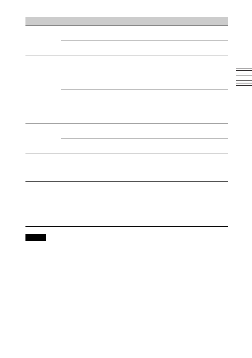
Others
Notes
Items Descriptions
Power
consumption
(Standby
Mode)
Power
consumption
(Networked
Standby
Mode)
AC 100 V to
120 V
AC 220 V to
240 V
AC 100 V to
120 V
AC 220 V to
240 V
0.50 W (when “Standby mode” is set to “Low”)
0.50 W (when “Standby mode” is set to “Low”)
12.5 W (LAN)
16.8 W (HDBaseT)
13.2 W (optional WLAN module)
17.4 W (all terminals and networks connected)
(when “Standby Mode” is set to “Standard”)
11.9 W (LAN)
17.0 W (HDBaseT)
12.6 W (optional WLAN module)
17.6 W (all terminals and networks connected)
Heat
dissipation
AC 100 V to
120 V
AC 220 V to
240 V
Standard
dimensions
(W/H/D)
(when “Standby Mode” is set to “Standard”)
VPL-PHZ11: 1,446 BTU/h
VPL-PWZ11: 1,361 BTU/h
VPL-PHZ11: 1,374 BTU/h
VPL-PWZ11: 1,286 BTU/h
Approx. 510 × 128.5 × 354.6 mm (20
31
/32inches)
13
Approx. 510 × 113 × 354.6 mm (20
inches) (without projecting parts)
32
3
/32 × 51/16 ×
3
/32 × 47/16 × 1331/
Mass Approx. 8.7 kg (19 lb)
Supplied
See “Checking the Supplied Accessories” in page 19.
accessories
Optional
accessories
*2 *3
USB wireless LAN module IFU-WLM3
*1: For details, refer to “Acceptable Input Signals” on page 96.
*2: Information on accessories in this manual is current as of September 2018.
*3: Not all optional accessories are available in all countries and area. Please check with
your local Sony Authorized Dealer.
Design and specifications of the unit, including the optional accessories, are
subject to change without notice.
Specifications
93
Page 94

Pin assignment
1
2
19
18
HDMI terminal (HDMI, female)
RGB input terminal (Mini D-sub
15-pin, female)
1 T.M.D.S.
Data2+
2 T.M.D.S.
Data2 Shield
3 T.M.D.S.
Data2 –
4 T.M.D.S.
Data1+
5 T.M.D.S.
Data1 Shield
6 T.M.D.S.
Data1 –
7 T.M.D.S.
Data0+
8 T.M.D.S.
Data0 Shield
9 T.M.D.S.
Data0 –
10 T.M.D.S.
Clock+
11 T.M.D.S.
Clock Shield
12 T.M.D.S.
Clock –
13 N.C.
14 RESERVED
(N.C.)
15 SCL
16 SDA
17 DDC GND
18 +5V Power
19 Hot Plug
Detect
1 Video input
(red) R
2 Video input
9Power supply
input for DDC
10 GND
(green) G
3 Video input
11 GND
(blue) B
4GND 12DDC/SDA
5 RESERVE 13 Horizontal
sync signal
6GND (R) 14Vertical sync
signal
7GND (G) 15DDC/SCL
8GND (B)
RS-232C terminal (D-Sub 9-pin,
male)
51
9
6
1NC 6NC
2RXDA 7RTS
3TXDA 8CTS
4DTR 9NC
5GND
94
Specifications
Page 95
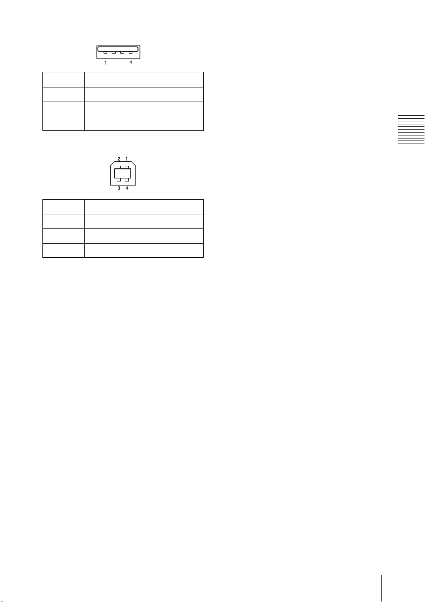
Others
USB terminal (Type A, female)
1V
2 Data–
3 Data+
4Ground
(4.4 - 5.25 V)
BUS
USB terminal (Type B, female)
1VCC (+5 V)
2 Data–
3 Data+
4Ground
Specifications
95
Page 96
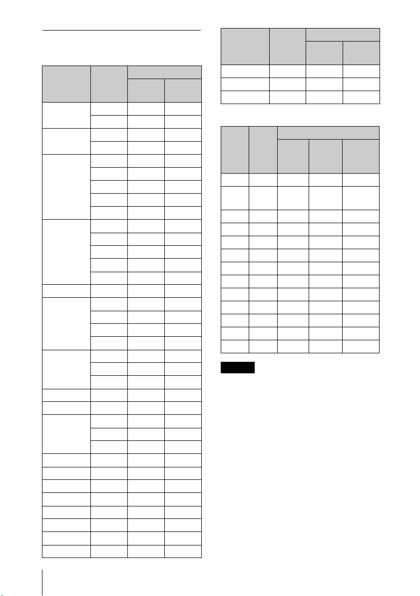
Acceptable Input Signals
Notes
Computer signal
Resolution
fH[kHz]/
fV[Hz]
640 × 350 31.5/70
37.9/85
640 × 400 31.5/70
37.9/85
640 × 480 31.5/60
35.0/67
37.9/73
37.5/75
43.3/85
800 × 600 35.2/56
37.9/60
48.1/72
46.9/75
53.7/85
832 × 624 49.7/75
1024 × 768 48.4/60
56.5/70
60.0/75
68.7/85
1152 × 864 64.0/70
67.5/ 75
77.5/85
1152 × 900 61.8/66
1280 × 960 60.0/60
1280 × 1024 64.0/60
80.0/75
91.1/85
1400 × 1050 65.3/60
1600 × 1200 75.0/60
1280 × 768 47.8/60
1280 × 720 45.0/60
1920 × 1080 67.5/60
1366 × 768 47.7/60
1440 × 900 55.9/60
1680 × 1050 65.3/60
*1
Input terminal
RGB/
YP
BPR
HDMI
*2
*3
Resolution
fH[kHz]/
fV[Hz]
1280 × 800 49.7/60
1920 × 1200 74.0/60
1600 × 900 60.0/60
Input terminal
RGB/
YP
BPR
*5
*5
HDMI
*5
*5
Video signal
Input terminal
Signal fV[Hz]
NTSC
PAL /
SECAM
480i
480p
576p
1080i
1080i
720p
720p
1080p
1080p
1080p
60 ––
50
60
576i
50
60
50
60
50
60
50
60
50
24
INPUT A
VIDEO
––
–
–
–
–
–
–
–
–
––
––
––
INPUT B/
INPUT C/
*4
INPUT D
*1: • When a signal other than the
signals listed in table is input, the
picture may not be displayed
properly.
• An input signal meant for screen
resolution different from that of
the panel will not be displayed in
its original resolution. Text and
lines may be uneven.
*2: This is identified as a movie delivery
signal of 720/60p.
*3: This is identified as a movie delivery
signal of 1080/60p.
*4: Only G with sync/Y is supported.
*5: Only VESA Reduced Blanking is
supported.
96
Specifications
Page 97
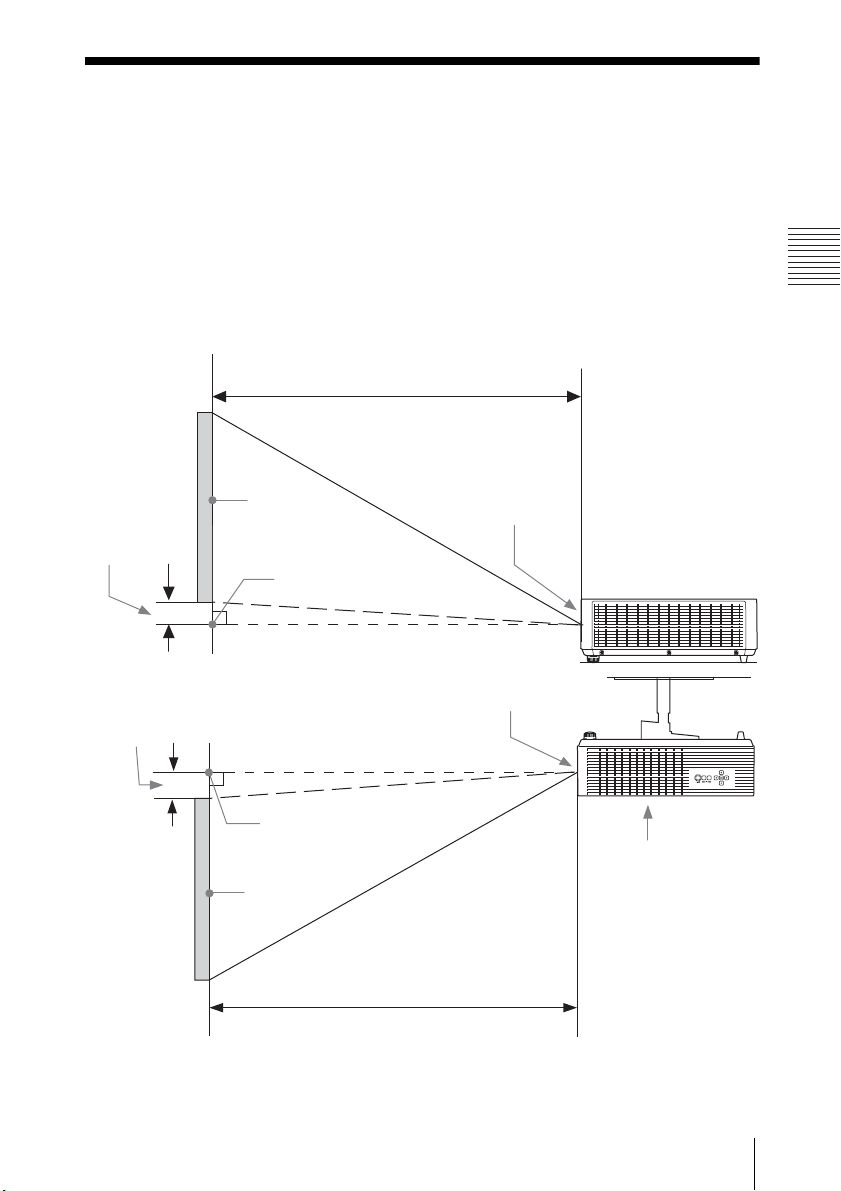
Others
Projection Distance and Lens Shift Range
Projection distance L
Projected
image
Front of the lens
A
Height H from
lens center to
bottom of
screen
Front of the lens
Height H from
lens center to
top of screen
A
Projected
image
Projection distance L
Top side
The following describes the projection distance and height from lens center to
bottom of screen by each projected screen size.
The projection distance is the distance between the front of the lens and the
surface of the projected image.
Height H is the height from the bottom of the projected image (top for ceiling
mount) to A (determined by drawing a perpendicular line from lens center to
projected image surface). For this unit, the same projection distance calculations
apply to both floor and ceiling installation.
Floor Installation/Ceiling Installation (Top side parallel to ceiling)
Projection Distance and Lens Shift Range
97
Page 98
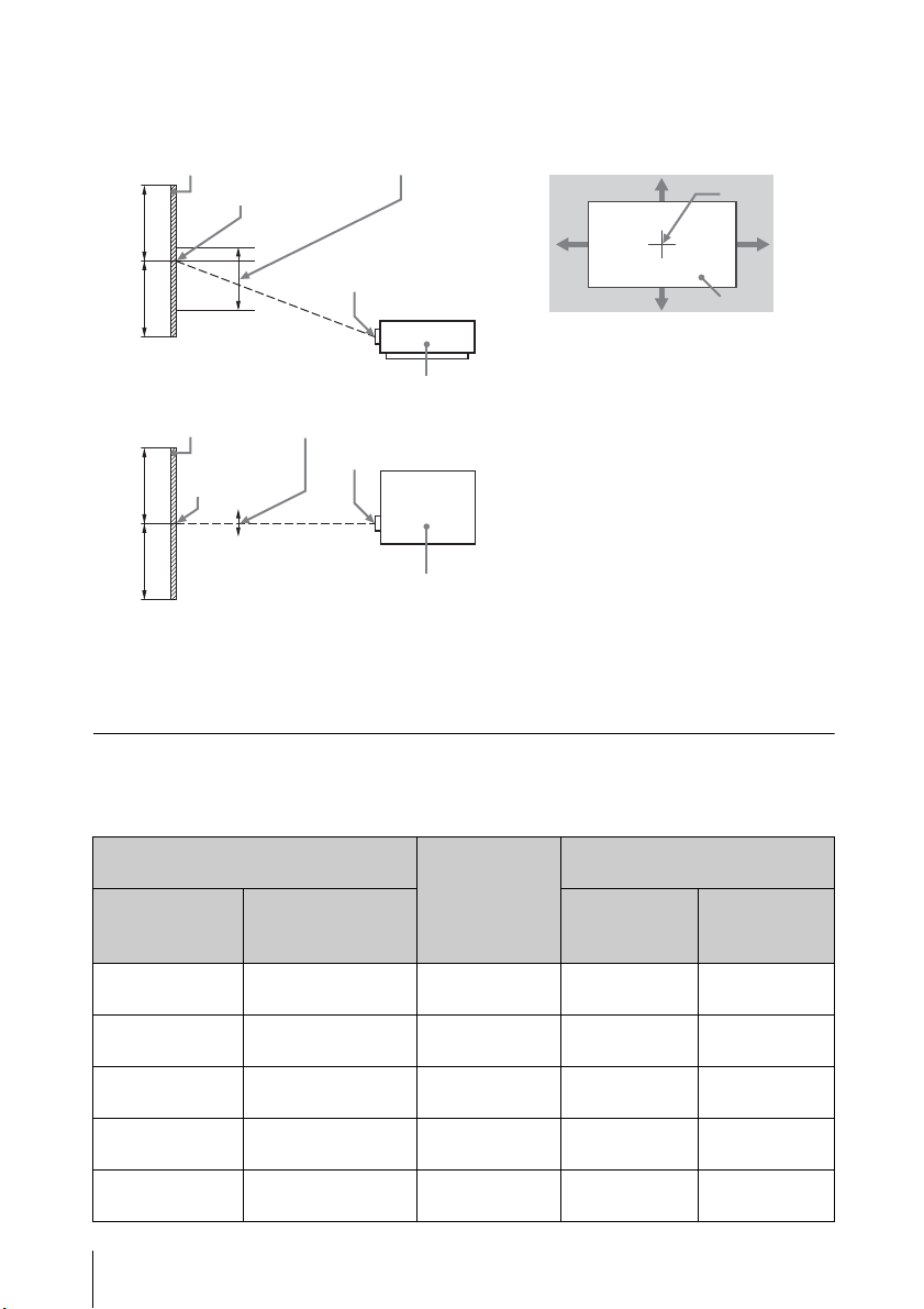
The lens shift range represents the distance in percent (%) by which the lens can
Center of the
image
Projected
image
VSUP
VSDN
HSL
HSR
Shaded region: Lens shift range
Projected image
Center of the
projected
image
Lens shift range
Center of the lens
Side of the projector
50%
50%
Projected image
Center of the
projected
image
Lens shift range
Center of the lens
Top of the projector
50%
50%
be shifted from the initial position of the projected image, with full width or full
height of the projected image regarded as 100%.
UP: Vertical lens shift range (up) [%]
VS
DN: Vertical lens shift range (down) [%]
VS
HS
R: Horizontal lens shift range (right) [%]
L: Horizontal lens shift range (left) [%]
HS
Projection distance/Projection distance formula
Projection distance
98
Projected image size
Diagonal Width × Height
80 inch
(2.03m)
100 inch
(2.54m)
120 inch
(3.05m)
150 inch
(3.81m)
200 inch
(5.08m)
Projection Distance and Lens Shift Range
1.72 × 1.08
(68 × 42)
2.15 × 1.35
(85 × 53)
2.58 × 1.62
(102 × 64)
3.23 × 2.02
(127 × 79)
4.31 × 2.69
(170 × 106)
Height H from lens center to
Projection
Distance L
2.18 - 3.23
(86 - 127)
2.74 – 4.06
(108 – 159)
3.30 – 4.88
(130 – 192)
4.13 – 6.11
(163 – 240)
5.53 – 8.16
(218 – 321)
Minimum
Projection
Distance L
-0.01 (0) -0.01 (0)
-0.01 (0) -0.01 (0)
-0.01 (0) -0.01 (0)
-0.01 (0) -0.01 (0)
-0.02 (-1) -0.02 (-1)
Unit: m (inches)
bottom of screen
Maximum
Projection
Distance L
Page 99
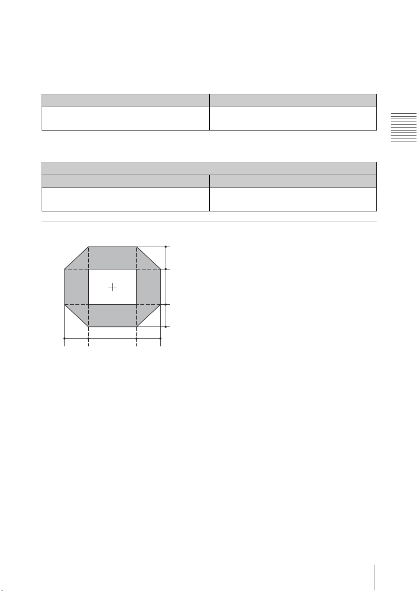
Others
Projection distance formula
10% H 10%
V
29.4%
5.6%
VS
DN = 29.4 [%]
HS
R = HSL = 10 [%]
VS
UP [%] = 5.6 - 0.560 × (HSR[%] or HSL[%])
VS
DN [%] = 29.4 - 2.940 × (HSR[%] or HSL[%])
HS
R [%] = HSL [%] = 10 - 1.786 × (VSUP[%])
HS
R [%] = HSL [%] = 10 - 0.340 × (VSDN[%])
D: Projection image size (")
Example) Enter 80 in D for the 80" projection image size.
H: Distance between the bottom edge of the image and the center of the lens
Expression#1 Unit: m (inches)
Minimum Projection Distance L Maximum Projection Distance L
L=0.027857 × D-0.0487
(L=1.096719 × D-1.9185)
L=0.041087 × D-0.0485
(L=1.617608 × D-1.9097)
Expression#2 Unit: m (inches)
Height H from lens center to bottom of screen
Minimum Projection Distance L Maximum Projection Distance L
H=-0.00008 × D+0.00000
(H=-0.00312 × D+0.00000)
H=-0.00008 × D+0.00000
(H=-0.00312 × D+0.00000)
Lens shift range
Projection Distance and Lens Shift Range
99
Page 100
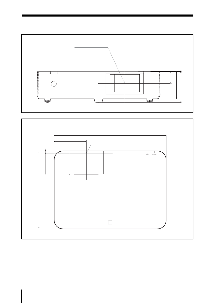
Dimensions
Front
Unit: mm (inches)
Center of the lens
113 (4
7
/
16
)
128 (5
1
/
32
)
50 (1
31
/
32
)
0.5 (
1
/
32
)
Side
Unit: mm (inches)
510 (20
3
/32)
10.1 (
13
/
32
)
354.6 (13
31
/
32
)
146.4 (5 3/4)
Center of the lens
100
Dimensions
 Loading...