


VPH-G90E/VPH-G90M/VPH-G90U
3-865-265-13 (2)
Multiscan Projector
Operating Instructions
Mode d’emploi
Manuel de instrucciones
GB
FR
ES
VPH-G90E
VPH-G90M
VPH-G90U
©1998 by Sony Corporation

English
WARNING
To prevent fire or shock hazard, do not expose
the unit to rain or moisture.
To avoid electrical shock, do not open the
cabinet. Refer servicing to qualified personnel
only.
This symbol is intended to alert the user
to the presence of uninsulated
“dangerous voltage” within the product’s
enclosure that may be of sufficient
magnitude to constitute a risk of electric
shock to persons.
This symbol is intended to alert the user
to the presence of important operating
and maintenance (servicing) instructions
in the literature accompanying the
appliance.
For the customers in the USA
Note
This equipment has been tested and found to comply with
the limits for a Class A digital device, pursuant to Part 15 of
the FCC Rules. These limits are designed to provide
reasonable protection against harmful interference when the
equipment is operated in a commercial environment. This
equipment generates, uses, and can radiate radio frequency
energy and, if not installed and used in accordance with the
instruction manual, may cause harmful interference to radio
communications. Operation of this equipment in a residential
area is likely to cause harmful interference in which case the
user will be required to correct the interference at his own
expense.
For the customers in Canada
This Class A digital apparatus complies with Canadian ICES-
003.
For the customers in the United Kingdom
WARNING
THIS APPARATUS MUST BE EARTHED
IMPORTANT
This wires in this mains lead are coloured in accordance with
the following code:
Green-and-Yellow: Earth
Blue: Neutral
Brown: Live
As the colours of the wires in the mains lead of this
apparatus may not correspond with the coloured markings
identifying the terminals in your plug proceed as follows:
The wire which is coloured green-and-yellow must be
connected to the terminal in the plug which is marked by the
letter E or by the safety earth symbol Y or coloured green or
green-and-yellow.
The wire which is coloured blue must be connected to the
terminal which is marked with the letter N or coloured black.
The wire which is coloured brown must be connected to the
terminal which is marked with the letter L or coloured red.
Voor de klanten in Nederland
• Dit apparaat bevat een Li-ion batterij voor memory back-
up.
• De batterij voor memory back-up van het geheugen is
bevestigd op IC333 van plaat YA.
• Raadpleeg uw leverancier over de verwijdering van de
batterij op het moment dat u het apparaat bij einde
levensduur afdankt.
• Gooi de batterij niet weg, maar lever hem in als KCA.
• Bij dit produkt zijn batterijen geleverd.
Wanneer deze leeg zijn, moet u ze niet
weggooien maar inleveren als KCA.
The socket-outlet should be installed near the equipment
and be easily accessible.
Warning
You are cautioned that any changes or modifications not
expressly approved in this manual could void your authority
to operate this equipment.
2 (GB) WARNING
2 (GB) Table of Contents

Table of Contents
Overview
Projecting
Precautions ..................................................................5 (GB)
Features........................................................................ 8 (GB)
Location and Function of Controls .......................... 10 (GB)
Front ............................................................................... 10 (GB)
Rear ................................................................................ 12 (GB)
Remote Commander/Control Panel ............................... 14 (GB)
Projecting ...................................................................18 (GB)
Adjusting the Picture ................................................ 21 (GB)
Centering Adjustment ...............................................22 (GB)
GB
English
Adjusting the Size And Shift of the Picture ............ 24 (GB)
SIZE adjustment............................................................. 24 (GB)
SHIFT adjustment .......................................................... 24 (GB)
Blanking adjustment ...................................................... 25 (GB)
Adjustments and settings using the menu
Using the Menu .......................................................... 26 (GB)
Basic Menu Operation ................................................... 26 (GB)
Menu Modes .................................................................. 27 (GB)
The PIC CTRL (Picture Control) Menu ..................... 29 (GB)
The PIC SETTING 1 (Picture Setting 1) Menu ......... 31 (GB)
The PIC SETTING 2 (Picture Setting 2) Menu ......... 32 (GB)
The INPUT SETTING Menu ....................................... 33 (GB)
The SET SETTING 1 Menu ........................................ 35 (GB)
The SET SETTING 2 Menu ........................................ 36 (GB)
The INPUT INFO (Information) Menu ....................... 38 (GB)
The SET INFO (Information) Menu ...........................39 (GB)
Table of Contents 3 (GB)

Table of Contents
Installation/connection examples
Installation Examples ................................................ 40 (GB)
Installation 1: Floor Installation Using Front Projection
Flat Screen ................................................................ 41 (GB)
Installation 2: Ceiling Installation Using Front Projection
Flat Screen ................................................................ 42 (GB)
Connection Examples ...............................................43 (GB)
Connecting Directly to the Projector ............................. 43 (GB)
Connecting Multiple Projectors ..................................... 44 (GB)
Using the PC-3000 Signal Interface Switcher ............... 46 (GB)
Confirming the System Construction............................. 47 (GB)
Using the PC-1271/1271M Signal Interface Switcher... 48 (GB)
Setting the Index Numbers .......................................49 (GB)
Maintenance / Other
Troubleshooting.........................................................52 (GB)
Specifications ............................................................ 53 (GB)
Index ........................................................................... 56 (GB)
4 (GB) Table of Contents

Precautions
On safety
Overview
Overview
• Check that the operating voltage of your unit is identical with the voltage
of your local power supply. If voltage adaptation is required, consult with
qualified Sony personnel.
• Should any liquid or solid object fall into the cabinet, unplug the unit and
have it checked by qualified personnel before operating it further.
• Unplug the unit from the wall outlet or set the MAIN POWER switch to
OFF if it is not to be used for several days.
• To disconnect the cord, pull it out by the plug. Never pull the cord itself.
• The wall outlet should be near the unit and easily accessible.
• The unit is not disconnected from the AC power source (mains) as long
as it is connected to the wall outlet, even if the unit itself has been turned
off.
On installation
• When the projector is mounted on the ceiling, the Sony PSS-90 Projector
Suspension Support must be used for installation. Read the installation
manual of the PSS-90 carefully, since the ceiling should be reinforced for
safety.
• Allow adequate air circulation to prevent internal heat build-up. Do not
place the unit on surfaces (rugs, blankets, etc.) or near materials (curtains,
draperies) that may block the ventilation holes. Leave space of more than
30 cm (12 inches) between the wall and the projector. Be aware that room
heat rises to the ceiling; check that the temperature near the installation
location is not excessive.
• Do not install the unit in a location near heat sources such as radiators or
air ducts, or in a place subject to direct sunlight, excessive dust or
humidity, mechanical vibration or shock.
Overview 5 (GB)

Precautions
Overview
On illumination
• To avoid moisture condensation, do not install the unit in a location
where the temperature may rise rapidly.
• Fans are installed inside the projector to prevent internal heat build-up.
The fans produce a humming noise when the power is switched on, which
is normal. Should the noise sound abnormal, please consult qualified
Sony personnel.
• To obtain the best picture, the front of the screen should not be exposed
to direct lighting or sunlight.
• Ceiling-mounted spot lighting is recommended. Use a cover over
fluorescent lamps to avoid lowering the contrast ratio.
• Cover any windows that face the screen with opaque draperies.
• It is desirable to install the projector in a room where floor and walls are
not of light-reflecting material. If the floor and walls are of reflecting
material, it is recommended that the carpet and wall paper be changed to
a dark color.
On operation
On cleaning
To turn on the projector after the projector has been turned off due to a
brief loss of power, press the ON key on the remote commander, or turn
off the MAIN POWER switch so that the STANDBY indicator turns off
and then turn on the MAIN POWER switch.
• To keep the cabinet looking new, periodically clean it with a soft cloth.
Stubborn stains may be removed with a cloth lightly dampened with a
mild detergent solution. Never use strong solvents, such as thinner,
benzene, or abrasive cleansers, since these will damage the cabinet.
• Avoid touching the lens. To remove dust on the lens, use a soft dry cloth.
Do not use a damp cloth, detergent solution, or thinner.
6 (GB) Overview

CRT burns
On repacking
When a static picture of a computer, etc. is displayed for more than about
an hour, a CRT burn may result. This means that an after-image
impression of the static picture remains on the screen even after the picture
has changed. If it is necessary to display the same static picture for more
than an hour, we recommend that you set the CONTR (contrast) control to
the lowest setting.
Also, when a picture of different size is displayed beyond a certain length
of time, an after-image impression of the frame of the smaller picture may
be burnt on the screen (such as displaying a 16:9 wide size picture on a 4:3
screen). To avoid this, we recommend that you use the same picture size
when possible. However, if it is necessary to use a different picture size,
set the CONTR (contrast) control and the BRT (brightness) control of the
smaller picture to the lowest setting possible. This will minimize the risk
of creating an after-image impression.
If the CRT burns, it must be replaced. In this case, refer to the warranty
provided with this unit. Consult your Sony dealer or Qualified Service
Personnel.
Overview
Save the original shipping carton and packing material; they will come in
handy if you ever have to ship your unit. For maximum protection, repack
your unit as it was originally packed at the factory.
Overview 7 (GB)

Features
Multiscan projector
Overview
1)
High resolution and brightness
High contrast
This projector accepts and automatically detects horizontal scanning
frequencies between 15 kHz and 150 kHz and vertical scanning
frequencies between 38 Hz and 150 Hz.
In addition to high-resolution pictures from computers, you can also
project pictures from teletext decoders, VCRs and video cameras.
A newly developed 9-inch electromagnetic focus CRT, a hybrid Sony
HACC (High-resolution Aspherical and Color Corrected) lens and a widerange cathode/G1 dual-drive video output circuit are incorporated in the
projector to provide a sharp and bright high-quality picture with the high
resolution of 2500 × 2000 pixels and the high light output of 350 lumen.
The adoption of the optical coupling technologies, double-focus lens
system and an anti-reflection coating gives a fine-detail and sharp picture
with improved contrast in corners and screen center.
Easy operation—remote control, on-screen display
Adjustments such as input selection, picture control and centering
adjustment can be remotely controlled from both the front and rear of the
projector with the supplied remote commander. You can also use the
commander as a wired remote control by connecting it to the projector
with the supplied remote control cable.
Compatible with various color systems
NTSC, PAL, SECAM, NTSC4.43 2) or PAL-M color system can be selected
automatically or manually.
..........................................................................................................................................................................................................
1)
1) The VPH-G90E model is not equipped with the VIDEO connectors.
To connect video signals, the optional IFB-G90E Video Interface Board is required.
2) NTSC4.43 is the color system used when playing back a video recorded on NTSC on a NTSC4.43 system VCR.
8 (GB) Overview

Flexible setup
You can project a 90- to 300-inch picture (120-inch standard) with this
projector. The projector can be set up on the floor or ceiling, for front or
rear projection to suit the installation location, surrounding illumination,
usage, etc.
Illuminated control panel/remote commander keys
The key names on the remote commander and the control panel of the
projector can be illuminated for easy access in a dark place by pressing the
LIGHT button.
Overview
DRC (Digital Reality Creation) circuit
The DRC is Sony’s unique double-scan technology which creates a 4times density image from the NTSC signal. A normal NTSC signal (525
scanning lines) is converted into a high density signal (1050 scanning
lines) using digital mapping tecnology. Compared with the conventional
double-scan, the DRC creates a highly realistic moving picture without
blurs.
1)
..........................................................................................................................................................................................................
1) The VPH-G90E model is not equipped with the VIDEO connectors.
To connect video signals, the optional IFB-G90E Video Interface Board is required.
Overview 9 (GB)

Overview
Location and Function of Controls
Front
123
6
5
4
7
1 Blue lens
2 Green lens
3 Red lens
4 Control panel cover
The control keys are inside the cover.
The locations and functions of the control keys are the
same as those of the remote commander.
For details, see “Remote Commander/Control Panel” on
page 14 (GB).
5 Handles
Used for carrying the projector. The handles are
located on the front, rear, left and right sides.
6 Front remote control detector
7 Adjusters
Used to keep the projector level if it is installed on an
uneven surface (equipped with four adjusters).
How to use the adjusters
Using the supplied tool, turn the adjusters to adjust the
height so that the projector becomes level.
To raise
Supplied tool
Notes
• The supplied tool can rotate the screw in one
direction only. To rotate the screw in the reverse
direction, turn the tool upside down.
• Do not turn the tool forcibly when the screw has fully
rotated. Otherwise, the tool may slip out and injure
your hand.
To lower
Supplied tool
10 (GB) Overview

Using the handles
Carry the projector with four persons or more by using the front, rear and
side (right and left) handles.
Pull out the front and rear handles or the side handles.
Overview
Putting away the handles
Push the handle release lever under each handle. The handle is
automatically retracted.
Overview 11 (GB)

Location and Function of Controls
Rear
Overview
5
6
7
STANDBY ONR
!¡ !º 9 8
OUT
IN
IN
OUT
1
2
3
4
R
OUT
IN
Y IN
C IN
G B SYNC/HD VD
R-Y/P
R
Y
B-Y/P
B
TRIGGER
LINK
VIDEO
IN
PLUG IN POWER
CONTROL S
OUT
S VIDEO
VIDEO
DEVICE INDEX
RS-232C RS-422A
!™ !£ !¢ !∞ !§ !¶
1 Signal interface board attachment part (INPUT
B)
An optional signal interface board such as IFB-12/12A
and IFB-40 can be attached to this section.
When the IFB-12/12A is attached, the signal input to
the INPUT A connectors can be output from the IFB12/12A by setting it to output mode.
2 MAIN POWER switch
3 AC IN socket
Connect the supplied AC power cord.
4 Signal interface board attachment part (INPUT
C)
An optional signal interface board can be attached to
this section.
Notes
• The IFB-40 cannot be attached to INPUT C.
• When the IFB-12/12A is attached, the IFB-12/12A
cannot be set to output mode.
INPUT A
RS-232C/422A
IN OUTPJ COM
REMOTE
5 ON indicator
When the projector is turned on, this indicator lights in
green.
6 u STANDBY indicator
When the MAIN POWER switch on the projector is
turned ON, this indicator lights in orange, indicating
that the projector can be turned on/off using the remote
commander.
7 Rear remote control detector
8 INPUT A connectors (BNC type)
R/R-Y/P
R, G/Y, B/B-Y/PB, SYNC/HD, VD
connectors: Connect to the outputs of a computer or a
video camera. According to the connected
equipment, the RGB (R, G, B), component (R-Y,
Y, B-Y) or HDTV (PR, Y, PB) signal is selected.
12 (GB) Overview

9 VIDEO connectors*
VIDEO IN connector (BNC type): Connects to the
composite video output of the video equipment.
VIDEO OUT connector (BNC type): Connects to the
composite video input of a color monitor.
S VIDEO IN/OUT connectors (4-pin, mini-DIN
type): Connects to the S video output or input of the
video equipment.
Y IN, C IN connectors (BNC type): Connects to the
Y and C video outputs of the video equipment.
Note
When using this jack, the remote control detector on
the projector does not function.
!¢ DEVICE INDEX switches
When multiple projectors are connected, set the device
index number of each projector.
To display the device index number on the screen,
press the NORMAL key, and the ENTER key on the
remote commander.
Overview
Note
The S VIDEO IN connector is disconnected when a
cable is connected to the Y IN/C IN connectors.
* Note on the VPH-G90E model
The optional IFB-G90E Video Interface Board is
required for using the VIDEO connectors.
!º LINK IN/OUT jacks (stereo minijack)
When connecting multiple projectors, connect the
LINK OUT jack to the LINK IN jack on another
projector. Then the link functions (ABL LINK, PIC
ORBITING LINK and SCAN LINE SHIFT LINK) can
be used.
!¡ TRIGGER connector (minijack)
When the projector is turned on, 12 V is output. When
it is turned off, 0 V is output. However, the connector
cannot be used as the power source.
!™ LED display window
Self-diagnosis results and PJ COM communication
conditions, etc. are displayed using two-digit numbers
and alphabets.
Self-diagnosis codes are displayed in red or orange,
and the warning and communication conditions in
green.
!£ CONTROL S jacks
IN/PLUG IN POWER jack (stereo minijack):
Connects to the CONTROL S OUT jack of other
Sony equipment. Also connects to the CONTROL
S OUT jack of the supplied remote commander
with the supplied remote control cable (stereo
cable) to be used as a wired remote control. In this
case, this jack supplies the power to the remote
commander to save the battery power.
OUT jack (stereo minijack): Connects to the
CONTROL S IN jack of other Sony equipment.
Note
Do not set the device index number to “00.” If you
do, the projector will not operate with the remote
commander.
You can operate the projector with the keys on the
control panel of the projector but the connected
equipment cannot be operated with the keys on the
control panel.
!∞ RS-232C/RS-422A selector
Selects the function of the RS-232C/RS-422A
connector.
!§ RS-232C/422A REMOTE connector (D-sub 9pin)
Used to expand the system connections using the RS232C/422A interface.
!¶ PJ COM (projector communication) IN/OUT
connectors (D-sub 9-pin)
These are the connectors conforming to the RS-485
standards, especially designed to expand the system
using Sony projectors.
Use these connectors to connect the PJ COM system of
the PC-3000 Signal Interface Switcher, or to activate
the linked picture orbiting function.
When the cable is connected to the IN connector only,
attach the supplied terminator to the OUT connector.
To connect multiple projectors, connect the IN
connector to the OUT connector of another projector
in cascade, and attach the supplied terminator to the
OUT connector of the last projector.
For details on the specifications of the connector, refer to
the Protocol Manual prepared by Sony.
Overview 13 (GB)

Location and Function of Controls
Remote Commander/Control Panel
The locations and functions of the keys on the remote
commander are the same as those on the control panel
Overview
of the projector. (Only the remote commander is
equipped with the transmission indicator and the
COMMAND ON/OFF switch.)
The remote commander may be used as a wired or
wireless remote control.
LIGHT
@∞
@¢
@£
@™
@¡
@º
!ª
!•
!¶
MUTING
PIC ONAUDIO OFF
NORMAL
APA
LCD LENS CONTROL
ZOOM
PATTERN
INPUT SELECT
VIDEO
SELECT
ADBC
SWITCHER/VIDEO MEMORY/INDEX
1423
5867
9
10/0(ALL)
STATUS
RGB
DOT PHASE
SHIFT
VIDEO/S VIDEO
SW NO/
OFF/GROUP
Notes
• The RGB APA/DOT PHASE 4, VOL +/– !§,
INPUT SELECT D !ª, LCD LENS CONTROL @£
and AUDIO MUTING @∞ keys do not function with
this projector.
• The RGB SIZE/SHIFT 4, CENT R/B 6 and BLKG
@¡ keys function only in the pro-user mode.
• The keys on the control panel are basically effective
for this projector only. Only the commands from the
SYS SET key and the switcher select commands are
transmitted to the connected equipment via the PJ
COM connector.
43215
COMMAND
OFF
SIZE
SHIFT
FOCUS
BLKG
SYS SET
SHARP
VIDEO MEMORY
SWITCHER
INDEX
6
ON
CENT
R
MEMORY
B
RESET
FUNCTION
PICTURE CONTROL
BRIGHT
HUE
7
CONTR
COLOR
8
MENU
ENTER
POSITION
ONSTANDBY
VOL
9
0
!¡
!™
!£
!¢
!∞
!§
1 LIGHT button
Illuminates the key indicators when the COMMAND
switch 5 is set to ON. If the COMMAND switch is
set to OFF, only the COMMAND switch is
illuminated.
The key indicators turn off if you press the LIGHT
button again.
If you do not press any key for more than 30 seconds,
the indicators also turn off automatically.
When the remote commander is connected to the
CONTROL S IN/PLUG IN POWER jack of the
projector via the remote control cable, the power is
supplied to the remote commander from the projector.
14 (GB) Overview
2 Transmission indicator (only for the remote
commander)
Lights each time you press a key. If it does not light,
replace the batteries with new ones.
3 STATUS ON/OFF keys
Press OFF to eliminate the on-screen display.
Press ON to restore the on-screen display.
Note
The menus and warning messages appear even if the
OFF key is pressed.

4 RGB keys
Adjust the picture.
APA: This key does not function with this projector.
DOT PHASE: This key does not function with this
projector.
SIZE: Enters the size adjustment mode for the input
signal in the pro-user mode. Next adjust the size of
the picture using the four arrow keys. Each time
you press this key, the COARSE and FINE modes
are switched alternately.
B: to reduce horizontal size
b: to expand horizontal size
V: to expand vertical size
v: to reduce vertical size
SHIFT: Enters the shift adjustment mode for the input
signal in the pro-user mode. Next adjust the
position of the picture using the four arrow keys.
The picture shifts in the direction of the arrow on
the pressed key. Each time you press this key, the
COARSE and FINE modes are switched
alternately.
!¡ ENTER key
Stores the settings in the menu, or selects and displays
the index number.
!™ FUNCTION key
Press to use the extended functions.
!£ RESET key
Resets the adjusted levels to the factory preset or
service adjusted levels.
!¢ POSITION +/– keys
Select the position to be adjusted on the screen in
focus, registration or blanking adjustment mode.
Also, set V SHIFT to WIDE or NARROW in RGB or
HDTV input signal’s SHIFT adjustment mode.
!∞ PICTURE CONTROL keys
Adjust the picture conditions: CONTR (contrast),
BRIGHT (brightness), COLOR, HUE and SHARP
(sharpness).
Overview
5 COMMAND ON/OFF switch (only for the
remote commander)
No keys on the remote commander except the LIGHT
button 1 function when this switch is set to OFF.
This saves battery power when a button is pressed
inadvertently.
6 CENT R/B keys
Enter the centering adjustment mode of the red and
blue in the pro-user mode.
R: Press to enter the red centering adjustment mode.
B: Press to enter the blue centering adjustment mode.
Perform the centering adjustment using the four arrow
keys.
7 MEMORY key
Stores various adjusted data into memory.
8 ON/SYANDBY keys
Turn on and off the projector when the MAIN
POWER switch on the projector is set to ON.
9 MENU key
Displays the main menu. Press it again to turn off the
menu.
0 Arrow keys
Adjust the value or select the item in the menu.
!§ VOL (volume) +/– keys
These keys do not function with this projector.
!¶ SWITCHER/VIDEO MEMORY/INDEX select
switch
Selects the function of the SWITCHER/VIDEO
MEMORY/INDEX keys.
SWITCHER: to select the input from the PC-3000 or
the PC-1271/1271M Signal Interface Switcher.
VIDEO MEMORY: to select the set and adjusted
video memory data.
INDEX: to select a projector by its index number
when multiple projectors are used.
!• SWITCHER/VIDEO MEMORY/INDEX keys
When the SWITCHER/VIDEO MEMORY/
INDEX select switch is set to SWITCHER
When the PC-3000 or the PC-1271/1271M Switcher
is connected to the projector, press a number key (1 to
8) to select the input from the switcher. Number key
9 and the 10/0 (ALL) key do not function.
To select an input when multiple switchers are
connected, set the SWITCHER/VIDEO MEMORY/
INDEX select switch to SWITCHER, then press the
SW NO/OFF/GROUP key. Next press the switcher
number (1 to 8) and the input number (1 to 8) in
sequence. Be sure to press the keys one after another
within 2 seconds.
e.g. To select input 4 of switcher 2, press the keys as
follows:
SW NO n 2 n 4.
Overview 15 (GB)

Location and Function of Controls
When the SWITCHER/VIDEO MEMORY/INDEX
select switch is set to VIDEO MEMORY
Select the number of the VIDEO MEMORY. To select
the data set and adjusted in INPUT MEMORY, press
the SW NO/OFF/GROUP key to set VIDEO
Overview
MEMORY to OFF.
Note
The 10/0 (ALL) key can be used as “10” key only
when the select switch is set to VIDEO MEMORY.
When the SWITCHER/VIDEO MEMORY/INDEX
select switch is set to INDEX
When multiple projectors are connected, select the
device index number of the projector to be adjusted.
Press the device index number (1 to 99) and press the
ENTER key. Be sure to press the keys one after
another within 2 seconds.
e.g. To select 1, press the keys as follows:
0 n 1 n ENTER, or 1 n ENTER.
To select 12, press the keys as follows:
1 n 2 n ENTER.
When adjusting all the projectors simultaneously, press
the 10/0 (ALL) key and ENTER key.
Note
Depending on the projector, pressing “0,” “0” and
“ENTER” is not effective.
!ª INPUT SELECT keys
Select the input signal.
VIDEO: Video or S video signal input from the
VIDEO connectors of the projector (VPH-G90U/
G90M) or the IFB-G90E Video Interface Board
(VPH-G90E).
SELECT VIDEO/S VIDEO: Selects video or S
video signal input from the VIDEO connectors
after pressing the VIDEO key.
A: The RGB, component or HDTV signal input from
the INPUT A connectors of the projector
B: The signal input from the INPUT B section when
the optional interface board other than the IFB-40
is installed
C: The signal input from the INPUT C section when
the optional interface board is installed.
D: This key does not function with this projector.
Note
To switch the input signal from the INPUT A, INPUT
B or INPUT C section to the S VIDEO IN (or Y IN/C
IN) connectors, first press the VIDEO key, then press
the SELECT VIDEO/S VIDEO key.
@º SYS SET (system set) key
When the PC-3000 Signal Interface Switcher is used
in the system, press the key to confirm the status of the
system, the settings of the interface board, and so on.
To select the projector to be adjusted when the
projectors are divided into multiple groups
First select the group index number and then the
projector’s device index number.
To select a group, press the SW NO/OFF/GROUP
key, the group index number (1 to 99) and the ENTER
key in sequence. When the group index has a doubledigit number, be sure to press the SW NO/OFF/
GROUP key before pressing each number key.
Then press the device index number of the projector (1
to 99) and finally press the ENTER key.
e.g. To select the index number 52 projector in group
91, press the keys as follows:
GROUP n 9 n GROUP n 1 n ENTER n 5
n 2 n ENTER.
@¡ BLKG (blanking) key
Enters the blanking adjustment mode in the pro-user
mode.
You can adjust the blanking with the four arrow keys.
For details, see “Blanking Adjustment” on page 25 (GB).
@™ PATTERN key
Displays the internal test patterns of the projector.
Each press of the key advances the test pattern
sequentially.
@£ LCD LENS CONTROL keys
These keys do not function with this projector.
@¢ NORMAL key
Erases the test pattern or cancels the various
adjustment modes.
@∞ MUTING keys
PIC (Picture): Cuts off the picture. To restore the
picture, press the key again.
AUDIO: This key does not funcion with this
projector.
16 (GB) Overview

Battery installation
1 Push to open the lid.
2 Install the three R6 (size AA) batteries (supplied)
with the correct polarity.
Be sure to install
the battery from
the ’ side.
3 Replace the lid.
Notes on wireless remote control operation
• Be sure that there is nothing to obstruct the infrared
beam between the remote commander and the
projector.
• The operation range is limited. The shorter the
distance between the remote commander and the
projector, the wider the angle within which the
remote commander can control the projector.
• The remote control detectors on the projector do not
operate when the remote commander is being used as
a wired remote control. If you wish to use the remote
commander as a wireless remote control, be sure to
remove the connecting cable from both the remote
commander and the projector.
Connecting the remote commander to the
projector
Rear of the projector
Overview
Notes on batteries
• Be careful that the battery orientation is correct when
inserting batteries.
• Do not mix old battery with new one, or different
types of batteries.
• If you do not intend to use the remote commander for
a long time, remove the batteries to avoid damage
from battery leakage. If a battery has leaked, remove
the batteries, wipe the battery compartment dry and
replace the batteries with new ones.
IN
OUT
PLUG IN POWER
CONTROL S
CONTROL S IN
CONTROL
S OUT
Remote control cable (supplied)
Overview 17 (GB)

Projecting
Projecting
Projecting
1, 6
Front remote control detector
STATUS ON/OFF keys
MUTING PIC key
4
SWITCHER/VIDEO MEMORY/
INDEX select switch and
number keys
LIGHT
MUTING
APA
LCD LENS CONTROL
ZOOM
INPUT SELECT
SELECT
10/0(ALL)
STATUS
DOT PHASE
SHIFT
VIDEO/S VIDEO
SW NO/
OFF/GROUP
PIC ONAUDIO OFF
NORMAL
PATTERN
VIDEO
ADBC
SWITCHER/VIDEO MEMORY/INDEX
1423
5867
9
RGB
SIZE
FOCUS
SYS SET
VIDEO MEMORY
SWITCHER
ON indicator/u STANDBY indicator/
Rear remote control detector (rear)
Control panel (inside the cover on the
top)
6
COMMAND
OFF
ON
CENT
R
MEMORY
SHIFT
B
BLKG
RESET
FUNCTION
PICTURE CONTROL
BRIGHT
HUE
SHARP
INDEX
CONTR
COLOR
ONSTANDBY
MENU
ENTER
POSITION
VOL
2
MENU key
18 (GB) Projecting
5
1 Press the MAIN POWER switch on the rear of the projector.
The u STANDBY indicator lights in orange and the projector goes
into the standby mode.

2 Press the ON key on the remote commander or the control panel.
The ON indicator on the rear of the projector lights in green.
A white screen with the message shown below (warming up screen)
appears on the screen. For getting a stable picture, make sure to allow
the projector to warm up for 20 minutes after turning it on.
The message disappears temporarily in about 35 seconds, and will
appear subsequently for 5 seconds every 30 seconds.
For optimum
performance,
white screen will
remain for
20min
For immediate use
push [MENU] key.
Press the MENU key to cancel the warming up screen and see the
picture immediately after the projector is turned on if, for example, the
adjustment has been finished and warming up is not needed.
3 Turn on the power of the connected equipment.
4 Select the input signal to be projected with the INPUT SELECT keys.
VIDEO and SELECT: To project the signal input from the
equipment connected to the VIDEO IN or S VIDEO IN (or Y IN/C IN)
connectors.
by pressing the SELECT key.
A: To project the RGB, component or HDTV signal input from the
equipment connected to the INPUT A connectors.
B: To project the signal input from the equipment connected to the
optional interface board other than the IFB-40 installed to the
INPUT B section.
C: To project the signal input from the equipment connected to the
optional interface board installed to the INPUT C section.
When the PC-3000 or PC-1271/1271M Signal Interface Switcher is
connected: Set the SWITCHER/VIDEO MEMORY/INDEX select
switch to SWITCHER and then select the input with the number
keys 1 to 8.
1)
Press the VIDEO key, then select VIDEO or S VIDEO
Projecting
Note
When you select the input signal connected to the INPUT A, INPUT B or
INPUT C section, be sure to select the correct signal in the SET SETTING
1 menu. If an incorrect signal is selected, picture may be distorted.
For details, see “The SET SETTING 1 Menu” on page 35 (GB).
..........................................................................................................................................................................................................
1) For the VPH-G90E model, the optional IFB-G90E Video Interface Board is required for using the VIDEO connectors.
Projecting 19 (GB)

Projecting
Projecting
5 Adjust the picture.
For details, see “Adjusting the picture” on page 21 (GB).
6 To turn the power off, press the STANDBY key on the remote
commander or on the control panel of the projector, then set the MAIN
POWER switch on the projector to OFF.
To Press
turn off the on-screen display the STATUS OFF key.
The menus and warning messages appear
even if the STANDBY key is pressed.
To restore the on-screen display, press the
STATUS ON key.
cut off the picture the MUTING PIC key.
To restore the picture, press the MUTING
PIC key.
20 (GB) Projecting

Adjusting the Picture
Adjust the picture for your preference. The adjustment data can be saved in
the memory.
1 Adjust with the PICTURE CONTROL +/– keys.
BRIGHT Brightness
CONTR Picture contrast
COLOR Color intensity
HUE Hue
SHARP Sharpness
The adjustment levels are digitally displayed with a range of MIN, 1,
2, ... 99, MAX.
BRIGHT: 50
Projecting
Restoring the initial data
2 Press the MEMORY key to save the data.
Adjusting the picture quality with the menu
Adjust CONTRAST, BRIGHT, COLOR, HUE and SHARP in the PIC
CTRL menu.
For details, see “The PIC CTRL Menu” on page 29 (GB).
1 Press the PICTURE CONTROL key of the item which you want to
reset to the initial data.
2 Press the RESET key.
The selected item is reset to the initial data.
Notes
• The COLOR, SHARP and HUE keys do not function with the RGB input
signals.
• The HUE and COLOR keys do not function if the input signal is black
and white.
• The HUE key does not function with the PAL or SECAM color input
source.
Projecting 21 (GB)

Centering Adjustment
The three colors, red, green and blue must converge for correct projection.
If they do not converge, centering adjustment is necessary.
Projecting
MAIN POWER switch (rear)
Front remote control detector
CENT R key
CENT B key
LIGHT
MUTING
PIC ONAUDIO OFF
NORMAL
PATTERN
VIDEO
ADBC
SWITCHER/VIDEO MEMORY/INDEX
STATUS
DOT PHASE
APA
LCD LENS CONTROL
ZOOM
SHIFT
INPUT SELECT
SELECT
VIDEO/S VIDEO
1423
5867
SW NO/
9
10/0(ALL)
OFF/GROUP
RGB
SIZE
FOCUS
SYS SET
VIDEO MEMORY
SWITCHER
Rear remote control detector
(rear)
Control panel (inside the cover
on the top)
MEMORY key
COMMAND
ON
OFF
CENT
R
MEMORY
SHIFT
B
BLKG
RESET
FUNCTION
PICTURE CONTROL
BRIGHT
HUE
SHARP
INDEX
CONTR
COLOR
ONSTANDBY
MENU
ENTER
POSITION
VOL
ON key
Arrow keys (V, v, B, b)
22 (GB) Projecting
1 Turn the projector on by switching on the MAIN POWER switch and
pressing the ON key on the remote commander.
2 Set the projector to the pro-user mode.
For details, see “Pro-user mode (P)” on page 28.
3 Press the CENT R key.
The built-in CROSS HAIR test pattern appears and the red line will be
adjustable.
Blue Green Red
R CENT ADJ
R CENT ADJ
R CENT ADJ
Hc:128
Hc:128
Hf:128
Hc:128
Hf:128
Vc:118
Hf:128
Vc:118
Vf:130
Vc:118
Vf:130
Vf:130
ADJ:
ADJ:
ADJ:
Red
Green
Blue

4 Press the arrow keys to move the red line until the red and green lines
converge and become yellow.
The red line moves according to the direction of the arrow.
Blue Yellow
R CENT ADJ
R CENT ADJ
Yellow
Hc:128
Hc:128
Hf:128
Hf:128
Vc:118
Vc:118
Vf:130
Vf:130
ADJ:
ADJ:
Blue
5 Press the CENT B key.
The blue line will be adjustable.
Blue Yellow
B CENT ADJ
B CENT ADJ
Yellow
Hc:128
Hc:128
Hf:128
Hf:128
Vc:118
Vc:118
Vf:130
Vf:130
ADJ:
ADJ:
Blue
Projecting
6 Press the arrow keys to move the blue line until the blue and yellow
lines converge.
The blue line moves according to the direction of the arrow.
When all three color lines converge, the test pattern will become white.
B CENT ADJ
Hc:128
Hf:128
Vc:118
Vf:130
ADJ:
7 Press the MEMORY key.
The normal display is restored.
Projecting 23 (GB)

Projecting
Adjusting the Size And Shift of the Picture
The size and shift of the input picture can be adjusted to fit the screen in
the pro-user mode only.
Note
When you connect multiple input sources to the projector, such as when
using the switcher, adjust the picture size, picture shift and blanking for
each input signal. The information about the input signal is shown in the
INPUT INFO menu.
SIZE adjustment
Adjust the picture size if it does not fit the screen.
1 Press the RGB SIZE key.
(Use the RGB SIZE key even for the signal other than RGB.)
2 Adjust the picture size with
the arrow keys.
V : The vertical size is
expanded.
v : The vertical size is
reduced.
b : The horizontal size is
expanded.
RGB SIZE ADJ
COARSE
Hc:[80]
Hf: 80
Vc: 80
Vf: 80
Picture
Screen
ADJ:
B : The horizontal size is
reduced.
To adjust precisely, press the RGB SIZE key again. The projector
enters the FINE adjustment mode, and you can fine adjust the size. By
pressing the RGB SIZE key again, the COARSE adjustment mode is
resumed.
3 Press the MEMORY key to save the adjustment data.
Resetting to the initial preset size
The picture size of the video signal can be reset to the initial preset size by
pressing the RESET key in RGB SIZE adjustment mode. (The picture size
of signals other than the video signal cannot be reset.)
SHIFT adjustment
24 (GB) Projecting
If the picture needs to be shifted to fit the screen, adjust the position of the
picture.
1 Press the RGB SHIFT key.
(Use the RGB SHIFT key even for the signal other than RGB.)
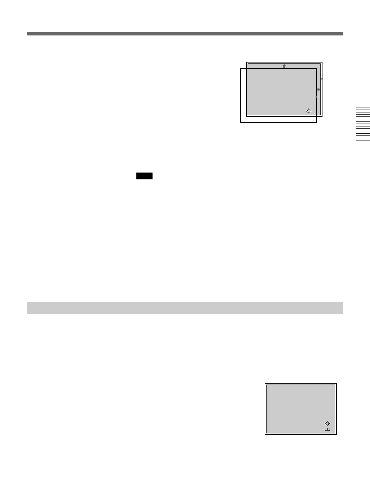
2 Adjust the shift with the arrow keys.
V : The picture is shifted
upward.
v : The picture is shifted
downward.
b : The picture is shifted
rightward.
B : The picture is shifted
leftward.
To adjust precisely, press the RGB SHIFT key again. The projector
enters the FINE adjustment mode, and you can fine adjust the
horizontal shift only. By pressing the RGB SHIFT key again, the
COARSE adjustment mode is resumed.
Note
When the RGB or HDTV signal is input, the adjustable range of the
vertical shift (V SHIFT) can be set to WIDE or NARROW by pressing the
POSITION +/– keys. When the video, S video, component or SDI 4 : 2 : 2
signal is input, V SHIFT is automatically fixed to NARROW and the
adjustable range of the vertical shift will become narrower than that of the
RGB or HDTV signal.
RGB SHIFT ADJ
COARSE V SHIFT:
NARROW
Hc:[50]
Hf: 50
V :MIN
ADJ:
Screen
Picture
Projecting
Blanking adjustment
3 Press the MEMORY key to save the adjustment data.
Resetting to the initial preset position
The position of the picture of the video signal can be reset to the initial
preset position by pressing the RESET key in RGB SHIFT adjustment
mode. (The position of the picture of signals other than the video signal
cannot be reset.)
If the displayed picture is larger than the screen, cut off the excess parts.
1 Press the BLKG key.
2 Press the POSITION +/– keys or the BLKG key to select the part to be
adjusted.
• When you press the + key or the
BLKG key, the position cycles
through the following order:
TOP n BOTTOM n LEFT n
RIGHT n TOP ...
• When you press the – key, the
position cycles in reverse order.
BLKG ADJ
TOP
T:[50]
B: 50
L:MAX
R: 50
ADJ:
NEXT:
+ –
3 Adjust with the arrow keys.
• Press the v and V keys to adjust the TOP and BOTTOM positions.
• Press the B and b keys to adjust the LEFT and RIGHT positions.
4 Press the MEMORY key to save the adjustment data.
Projecting 25 (GB)

Using the Menu
Adjustments and
settings using the menu
Adjustments and settings using the menu
The projector is equipped with an on-screen menu for
making various adjustments and settings.
There are two menu modes: user mode and pro-user
mode, to limit the menu items according to the level of
the operator of the projector.
Basic Menu Operation
1 Press the MENU key.
The menu display appears.
The menu presently selected is highlighted in blue.
VIDEO
VIDEO MEMORY
PIC
CTRL
No.10
16:9 NTSC SIGNAL
SET
SETTING1
CONTRAST 80
BRIGHT 50
SET
SETTING2
COLOR 50
HUE 50
INPUT
INFO.
SHARP 50
SEL: SET: ENTER
EXIT: M ENU
2 Use the v or V keys to select a menu, then press
the b key or the ENTER key.
The selected menu appears.
The setting items that are indicated in white
cannnot be selected.
Menu items
VIDEO
VIDEO MEMORY
PIC
CTRL
No.10
16:9 NTSC SIGNAL
SET
SETTING1
CONTRAST 80
BRIGHT 50
SET
SETTING2
COLOR 50
HUE 50
INPUT
INFO.
SHARP 50
Setting items
SEL: SET: ENTER
EXIT: M ENU
3 Use the v or V keys to select a setting item, then
press the b key or the ENTER key.
The adjustment menu or the setting menu (pop-up
menu) appears.
To go to the next page
If there are two or more pages for a menu, the $
indication appears below the bottom item. Move
the cursor to the bottom item with the v key, then
press the v key.
To go back to the previous page
Move the cursor to the top item with the V key,
then press the V key.
26 (GB) Adjustments and settings using the menu

4 Make adjustment or setting on the menu.
Menu Modes
To change the adjustment level
To increase the level, press the V or b key.
To decrease the level, press the v or B key.
Then press the ENTER key to store the level. The
original screen is restored.
CONTRAST: 80
To select an item
Use the v or V key to select an item in a pop-up
menu. For some items, the result or effect of the
selection is simultaneously reflected on the screen.
For other items, press the B key or the ENTER key
to confirm the selection. The selected setting is
stored and the pop-up menu disappears.
Pop-up menu
VIDEO
STATUS:ON
PIC
CTRL
PIC MUTING:OFF
INPUT-A:RGB
SET
SETTING1
INPUT-B:RGB
INPUT-C:RGB
SET
SETTING2
INPUT
INFO.
SEL:
RGB
COMPONENT
HDTV-YPBPR
HDTV-GBR
SET: ENTER
EXIT: M ENU
There are two menu modes for this projector.
User mode
This is the menu mode for end users. Only the
minimum menu items for usual settings and
adjustments appear in this mode.
No indication for user mode
VIDEO
VIDEO MEMORY
PIC
CTRL
No.10
SET
SETTING1
CONTRAST 80
BRIGHT 50
SET
SETTING2
COLOR 50
HUE 50
INPUT
INFO.
SHARP 50
The user mode is factory preset. By pressing the
MENU key for the first time, the user mode appears.
16:9 NTSC SIGNAL
SEL: SET: ENTER
EXIT: MENU
Adjustments and settings using the menu
For details on setting individual items, see the relevant
menu pages.
To clear the menu display
Press the MENU key or NORMAL key.
The menu display also disappears automatically if no
key is pressed for about one minute.
Memory of the settings
The settings in the menus are automatically stored in
the projector memory. You can also store the settings
by pressing the MEMORY key.
Adjustments and settings using the menu 27 (GB)

Using the Menu
Pro-user mode (P)
This is the menu mode for advanced end users who
know the operation and functions of the projector very
well. The menu items for detailed settings and
adjustments are provided so that they can get the most
of the projector functions.
Pro-user mode indication
VIDEO
P
D.PICTURE:OFF
PIC
CTRL
COLOR SYS:AUTO
SET UP:0
PIC
SETTING1
COMPONENT FORMAT
PIC
SETTING2
INPUT
SETTING
SET
Adjustments and settings using the menu
SETTING1
SEL:
SET: ENTER
EXIT: MENU
To set to the pro-user mode
1 Press the MENU key.
The menu in the user mode appears.
5 Press the MENU key.
The menu in the pro-user mode appears with the
letter “P” at the top-left of the screen.
VIDEO
P
VIDEO MEMORY
PIC
CTRL
No.10
16:9 NTSC SIGNAL
PIC
SETTING1
CONTRAST 80
BRIGHT 50
PIC
SETTING2
COLOR 50
HUE 50
INPUT
SETTING
SHARP 50
SET
SETTING1
To reset to the user mode
Perform the same steps for setting to the pro-user
mode, and set USER MODE in the SET SETTING 1
menu to NORMAL.
Press the ENTER or B key to turn off the menu. When
the MENU key is pressed again, the menu in the user
mode appears.
SEL: SET: ENTER
EXIT: M ENU
2 Press the v or V key to select SET SETTING 1,
then press the ENTER or b key.
VIDEO
STATUS:ON
PIC
CTRL
PIC MUTING:OFF
INPUT-A:RGB
SET
SETTING1
INPUT-B:RGB
INPUT-C:RGB
SET
SETTING2
USER MODE:NORMAL
INPUT
INFO.
SEL:
SET: ENTER
EXIT: M ENU
3 Press the v or V key to select USER MODE, then
press the ENTER or b key.
VIDEO
STATUS:ON
PIC
CTRL
PIC MUTING:OFF
INPUT-A:RGB
SET
SETTING1
INPUT-B:RGB
INPUT-C:RGB
SET
SETTING2
USER MODE:NORMAL
INPUT
INFO.
SEL:
SET: ENTER
EXIT: M ENU
4 Press the v or V key to select PRO in the pop-up
menu, then press the ENTER or B key.
The menu disappears.
28 (GB) Adjustments and settings using the menu

The PIC CTRL (Picture Control) Menu
[User/Pro-user modes]
The PIC CTRL menu is used for adjusting the picture.
Items that can be adjusted are highlighted in green.
You cannot select the items indicated in white.
VIDEO
VIDEO MEMORY
PIC
CTRL
No.10
SET
SETTING1
CONTRAST 80
BRIGHT 50
SET
SETTING2
COLOR 50
HUE 50
INPUT
INFO.
SHARP 50
16:9 NTSC SIGNAL
SEL: SET: ENTER
EXIT: MENU
VIDEO MEMORY
Selects the number of video memory 1 to 10.
VIDEO
VIDEO MEMORY
PIC
CTRL
No.10
16:9 NTSC SIGNAL
SET
SETTING1
CONTRAST 80
BRIGHT 50
SET
SETTING2
COLOR 50
HUE 50
INPUT
INFO.
SHARP 50
The video memory is a part of the SET MEMORY,
and stores 10 types of the aspect ratio, picture quality,
etc.
Select a video memory number 1 to 10, then the
aspect ratio and picture quality that you adjust will be
stored in the selected video memory.
If you want to use the aspect ratio and picture quality
data stored in the INPUT MEMORY, select OFF.
SEL: SET: ENTER
EXIT: M ENU
To select the number of video memory
After selecting VIDEO MEMORY, press the b or
ENTER key. The following VIDEO MEMORY select
menu appears. Select the desired number with the v
and V keys, then press the B or ENTER key.
Z
VIDEO MEMORY
4
No. LABEL
1
4:3 STSC SIGNAL
2 16:9 NTSC SIGNAL
3 4:3 SECAM SIGNAL
4 16:9 SECAM SIGNAL
5 4:3 PAL SIGNAL
6 16:9 PAL SIGNAL
7 4:3 PAL-M SIGNAL
8 16:9 PAL-M SIGNAL
SEL: SET: ENTER
EXIT: M ENU
Aspect ratios preset at the factory
The data for the following aspect ratios have been
stored in each video memory number at the factory.
No. Aspect ratio
1 4 : 3
2 4 : 3
3 4 : 3
4 4 : 3
5 4 : 3
6 16 : 9
7 16 : 9
8 16 : 9
9 16 : 9
10 16 : 9
To change the video memory label (in Prouser mode only)
You can change the label of the video memory to
match the memory contents.
Adjustments and settings using the menu
Contents of the video memory data
COLOR TEMPERATURE, D. PICTURE, V SHIFT
WIDE/NARROW, COMPONENT FORMAT, COMB
FILTER, DRC LEVEL, CONTRAST, BRIGHT,
COLOR, HUE, SHARP, RGB SIZE, RGB SHIFT,
BLANKING
When the VIDEO MEMORY select menu is
displayed, select the number you want change its label
and press the b key. The following display appears.
[4:3 NTSC SIGNAL ]
ABCDEFGHIJKLMN
OPQRSTUVWXYZ .
0123456789-_*:
OKnN CANCEL
ENTER
SEL:
EXIT: M ENU
SET:
Move the cursor to the desired letter with the v/V/B/b
keys, then press the ENTER key. The selected letter is
displayed in the [ ] at the top of the screen. You can
select up to 18 letters by repeating the same procedure.
After selecting the letters, move the cursor to OK, then
press the ENTER button. The display is returned to
the VIDEO MEMORY select menu.
Adjustments and settings using the menu 29 (GB)

The PIC CTRL (Picture Control) Menu
CONTRAST
Adjusts the picture contrast.
CONTRAST: 80
The higher the setting, the greater the contrast.
The lower the setting, the lower the contrast.
BRIGHT (brightness)
Adjusts the picture brightness.
Adjustments and settings using the menu
BRIGHT: 50
HUE
Adjusts skin tones.
HUE: 50
At high settings, the picture becomes greenish.
At low settings, the picture becomes purplish.
SHARP (sharpness)
Adjusts the picture sharpness.
SHARP: 50
The higher the setting, the brighter the picture.
The lower the setting, the darker the picture.
COLOR
Adjusts color intensity.
COLOR: 50
The higher the setting, the greater the intensity.
The lower the setting, the lower the intensity.
The higher the setting, the sharper the picture.
The lower the setting, the softer the picture.
Input signals and adjustable/setting items
Input signal
Item
VIDEO
MEMORY
CONTRAST
BRIGHT
COLOR
HUE
SHARP
Y: Adjustable/can be set
N: Not adjustable/cannot be set
* For the VPH-G90E model, the optional IFB-G90E Video
Interface Board is required.
Video or
S video (Y/C)*
Y
Y
Y
Y
Y
3.58 /
(NTSC
NTSC4.43
system only)
Y
Component
SDI 4:2:2
Y
Y
Y
Y
Y
Y
HDTV
Y
Y
Y
Y
Y
Y
RGB
Y
Y
Y
N
N
N
30 (GB) Adjustments and settings using the menu

The PIC SETTING 1 (Picture Setting 1) Menu
[Pro-user mode]
The PIC SETTING 1 menu is used for setting the
picture quality.
Items that can be set are highlighted in green.
You cannot select the items indicated in white.
VIDEO
P
D.PICTURE:OFF
PIC
CTRL
COLOR SYS:AUTO
SET UP:0
PIC
SETTING1
COMPONENT FORMAT
PIC
SETTING2
INPUT
SETTING
SET
SETTING1
SEL: SET: ENTER
EXIT: MENU
D. (Dynamic) PICTURE
Emphasizes the black of the composite video, S video
(Y/C) or component signal.
VIDEO
P
D.PICTURE:OFF
PIC
CTRL
COLOR SYS:AUTO
SET UP:0
PIC
SETTING1
COMPONENT FORMAT
PIC
SETTING2
INPUT
SETTING
SET
SETTING1
SEL: SET: ENTER
EXIT: M ENU
SET UP
Changes the set up level (standard black level) to 0
IRE or 7.5 IRE according to the NTSC source signal.
VIDEO
P
D.PICTURE:OFF
PIC
CTRL
COLOR SYS:AUTO
SET UP:0
PIC
SETTING1
COMPONENT FORMAT
PIC
SETTING2
INPUT
SETTING
SET
SETTING1
SEL: SET: ENTER
EXIT: M ENU
0 (0 IRE): Normally, set to this position.
7.5 (7.5 IRE): Set to this position when the black color
is too light.
COMPONENT FORMAT
Selects the format of the component input signal.
INPUT-A
P
D.PICTURE:OFF
PIC
CTRL
COLOR SYS:
SET UP:
PIC
SETTING1
COMPONENT FORMAT:
SMPTE/EBU-N10
PIC
SETTING2
INPUT
SETTING
SET
SETTING1
SEL: SET: ENTER
EXIT: M ENU
Adjustments and settings using the menu
ON: Emphasizes the black to produce a bolder
“dynamic” picture.
OFF: Reproduces the dark portions of the picture
accurately, in accordance with the source signal.
COLOR SYS (System)
Selects the color system of the composite video or S
video (Y/C) signal.
VIDEO
P
D.PICTURE:OFF
PIC
CTRL
COLOR SYS:AUTO
SET UP:0
PIC
SETTING1
COMPONENT FORMAT
PIC
SETTING2
INPUT
SETTING
SET
SETTING1
Select among AUTO, NTSC3.58, PAL, SECAM,
NTSC4.43 and PAL-M.
Normally, set to AUTO.
If the picture is distorted or colorless, select the color
system according to the input signal.
SEL: SET: ENTER
EXIT: M ENU
SMPTE/EBU-N10: Set to this position if the input
signal is the SMPTE or EBU-N10 format
component signal.
BETACAM7.5: Set to this position if the input signal
is the Betacam format component signal.
Input signals and adjustable/setting items
Input signal
Item
D. PICTURE
COLOR SYS
SET UP
COMPONENT
FORMAT
Y: Adjustable/can be set
N: Not adjustable/cannot be set
Video or
S video (Y/C)*
Y
Y
Y
3.58/
(NTSC
NTSC4.43
system only)
N
Component
SDI 4:2:2
Y
N
N
Y
HDTV
N
N
N
N
RGB
N
N
N
N
* For the VPH-G90E model, the optional IFB-G90E Video
Interface Board is required.
Adjustments and settings using the menu 31 (GB)

The PIC SETTING 2 (Picture Setting 2) Menu
[Pro-user mode]
The PIC SETTING 2 menu is used for setting the
picture quality.
Items that can be set are highlighted in green.
You cannot select the items indicated in white.
VIDEO
P
COMB FILTER:3D
PIC
CTRL
DRC:ON
DRC LEVEL:HIGH
PIC
SETTING1
PIC
SETTING2
INPUT
SETTING
SET
SETTING1
SEL: SET: ENTER
EXIT: MENU
COMB FILTER
Adjustments and settings using the menu
Selects the comb filter which reduces the cross color
and dot interference of the NTSC signal to reproduce
clear images.
VIDEO
P
COMB FILTER:3D
PIC
CTRL
DRC:ON
DRC LEVEL:HIGH
PIC
SETTING1
PIC
SETTING2
INPUT
SETTING
SET
SETTING1
SEL: SET: ENTER
EXIT: M ENU
3D: Three-dimensional comb filter. Normally use this
comb filter.
3LINE: 3LINE comb filter. This comb filter may be
more effective for fast-moving pictures.
DRC (Digital Reality Creation)
Set to ON to make the NTSC signal 4-times density
image.
VIDEO
P
COMB FILTER:3D
PIC
CTRL
DRC:ON
DRC LEVEL:HIGH
PIC
SETTING1
PIC
SETTING2
INPUT
SETTING
SET
SETTING1
SEL: SET: ENTER
EXIT: M ENU
Note
The DRC is effective only when the 15 kHz signal
complies with the timing of the video signal. If it has a
particular timing, the image may be disturbed with the
DRC ON.
DRC LEVEL
Selects the effect of the DRC for the NTSC signal.
This item can be selected only for an interlaced signal.
VIDEO
P
COMB FILTER:3D
PIC
CTRL
DRC:ON
DRC LEVEL:HIGH
PIC
SETTING1
PIC
SETTING2
INPUT
SETTING
SET
SETTING1
SEL: SET: ENTER
EXIT: M ENU
HIGH is preset at the factory. Select LOW if the
picture is glaring.
Input signals and adjustable/setting items
Input signal
Item
COM FILTER
DRC
DRC LEVEL
Y: Adjustable/can be set
N: Not adjustable/cannot be set
* For the VPH-G90E model, the optional IFB-G90E Video
Interface Board is required.
Video or
S video (Y/C) *
Y
(NTSC3.58
system only)
Y
Y
Component
SDI 4:2:2
N
Y
Y
HDTV
N
N
N
RGB
N
Y
(15 kHz
RGB
only)
Y
(15 kHz
RGB
only)
Normally set to ON. When a 15 kHz signal is input,
the DRC function activates. When the DRC is not
required, set to OFF.
32 (GB) Adjustments and settings using the menu

The INPUT SETTING Menu [Pro-user mode]
The INPUT SETTING menu is used to adjust the input
signal.
Items that can be adjusted are displayed in green.
You cannot select the items indicated in white.
INPUT-A
P
COLOR TEMP:6500
PIC
CTRL
CLAMP:AUTO
V SHIFT:WIDE
PIC
SETTING1
SYNC SEL:AUTO
SYNC ROUTE:AUTO
PIC
SETTING2
VIDEO LOCK:NORMAL
INPUT
SETTING
SET
SETTING1
SEL: SET:
ENTER
EXIT: MENU
COLOR TEMP (Temperature)
Selects the appropriate color temperature according to
your application and the input source signal.
INPUT-A
P
COLOR TEMP:6500
PIC
CTRL
CLAMP:AUTO
V SHIFT:WIDE
PIC
SETTING1
SYNC SEL:AUTO
SYNC ROUTE:AUTO
PIC
SETTING2
VIDEO LOCK:NORMAL
INPUT
SETTING
SET
SETTING1
SEL: SET:
ENTER
EXIT: M ENU
CLAMP is used as a standard for setting the black
level of a picture correctly. The standard position of
the clamp depends on the kind of sync signal being
used. Normally, the projector CPU judges the signal
and sets the position automatically. However, the CPU
can misjudge the signal because of noise. If the
luminance of the picture seems to be incorrect, the
clamp position may need to be changed.
AUTO: Automatic setting mode. Normally set to this
position.
SonG: Set to this position if the black seems too light
or greenish.
H/C: Set to this position if the picture is too dark or
luminance is unstable.
HP: If the luminance is still incorrect after changing to
the SonG or H/C position, set to this position and
perform the H-SHIFT adjustment.
TRI-LEVEL S: Set to this position if the picture is
dark when using the tri-level sync.
Notes
• If the external signal does not have the SonG signal,
the H/C position is recommended.
• If the luminance is still incorrect after changing the
clamp setting, check the input signal and the
connections.
Adjustments and settings using the menu
9300: standard color temperature for consumer-use
products
6500: standard color temperature for business-use
products
5400: standard color temperature for HDTV
3200: standard color temperature for medical products
and studio cameras
CUSTOM: If you wish to make the color of a
particular input signal uniform to that of another
display, select CUSTOM, then adjust the white
balance.
CLAMP
Corrects the luminance of the input picture.
INPUT-A
P
COLOR TEMP:6500
PIC
CTRL
CLAMP:AUTO
V SHIFT:WIDE
PIC
SETTING1
SYNC SEL:AUTO
SYNC ROUTE:AUTO
PIC
SETTING2
VIDEO LOCK:NORMAL
INPUT
SETTING
SET
SETTING1
SEL: SET:
ENTER
EXIT: M ENU
V (Vertical) SHIFT
Sets the adjustable range of the vertical shift of the
input signal.
INPUT-A
P
COLOR TEMP:6500
PIC
CTRL
CLAMP:AUTO
V SHIFT:WIDE
PIC
SETTING1
SYNC SEL:AUTO
SYNC ROUTE:AUTO
PIC
SETTING2
VIDEO LOCK:NORMAL
INPUT
SETTING
SET
SETTING1
WIDE: Normally, set to this position (factory preset).
NARROW: When some signal such as a
superimposed signal with unstable vertical sync.
signal is input, the picture may be distorted
vertically. In this case, set to this position.
Adjustable range in the lower direction will
become narrow.
Note
When the video, S video, component or SDI 4:2:2
signal is input, V SHIFT is fixed to NARROW.
SEL: SET:
ENTER
EXIT: M ENU
Adjustments and settings using the menu 33 (GB)

The INPUT SETTING Menu
SYNC SEL (select)
Selects the sync signal when using an external sync
signal.
INPUT-A
P
COLOR TEMP:6500
PIC
CTRL
CLAMP:AUTO
V SHIFT:WIDE
PIC
SETTING1
SYNC SEL:AUTO
SYNC ROUTE:AUTO
PIC
SETTING2
VIDEO LOCK:NORMAL
INPUT
SETTING
SET
SETTING1
SEL: SET:
ENTER
EXIT: M ENU
When an RGB signal is input
AUTO: Automatic setting mode. Normally set to this
position.
SonG: Set to this position if you project the picture
using the sync on G signal.
C: Set to this position if you project the picture using
Adjustments and settings using the menu
the composite sync signal.
HV: Set to this position when using the horizontal/
vertical sync signal.
When an HDTV signal is input
You can select the items below instead of the above
items.
AUTO: Automatic setting mode. Normally set to this
position.
INT: Set to this position when using the internal sync
signal.
EXT [C]: Set to this position when using the external
composite sync signal.
EXT [HV]: Set to this position when using the
external horizontal/vertical sync signal.
Note
For an RGB signal, this item can be selected only
when SonG and C/HV are included.
SYNC ROUTE
Selects the route of the sync signal when the RGB
signal is input to INPUT A.
INPUT-A
P
COLOR TEMP:6500
PIC
CTRL
CLAMP:AUTO
V SHIFT:WIDE
PIC
SETTING1
SYNC SEL:AUTO
SYNC ROUTE:AUTO
PIC
SETTING2
VIDEO LOCK:NORMAL
INPUT
SETTING
SET
SETTING1
SEL: SET:
ENTER
EXIT: M ENU
AUTO: Automatic setting mode. Normally set to this
position.
NORMAL: Set to this position for a normal sync
input, that is, when there is no video signal on the
sync line.
SYNC w VIDEO: Set to this position when the video
signal is on the sync line and the sync of the image
is distorted in the AUTO position.
VIDEO LOCK
Selects the range of the frequency deviation of the
input signal so that the INPUT MEMORY data is
switched automatically if the frequency deviation
exceeds the selected range. This item can be selected
only for RGB input signals.
INPUT-A
P
COLOR TEMP:6500
PIC
CTRL
CLAMP:AUTO
V SHIFT:WIDE
PIC
SETTING1
SYNC SEL:AUTO
SYNC ROUTE:AUTO
PIC
SETTING2
VIDEO LOCK:NORMAL
INPUT
SETTING
SET
SETTING1
SEL: SET:
ENTER
EXIT: M ENU
NORMAL: Normally set to this position.
WIDE: Set to this position if the input signal is
unstable or flickers. This phenomenon may appear
during variable speed playback by the VCR. etc.
Input signals and adjustable/setting items
Input signal
Item
COLOR
Video or
S video (Y/C)*
Y
Component
SDI 4:2:2
Y
TEMP
CLAMP
V SHIFT
SYNC SEL
SYNC
N
N
N
N
N
N
N
N
ROUTE
VIDEO
N
N
LOCK
Y: Adjustable/can be set
N: Not adjustable/cannot be set
* For the VPH-G90E model, the optional IFB-G90E Video
Interface Board is required.
HDTV
Y
N
Y
Y
N
N
RGB
Y
Y
Y
Y
Y
Y
34 (GB) Adjustments and settings using the menu

The SET SETTING 1 Menu [User/Pro-user modes]
The SET SETTING 1 menu is used for changing the
default settings of the projector.
Items that can be adjusted are highlighted in green.
You cannot select the items indicated in white.
VIDEO
STATUS:ON
PIC
CTRL
PIC MUTING:OFF
INPUT-A:RGB
SET
SETTING1
INPUT-B:RGB
INPUT-C:RGB
SET
SETTING2
USER MODE:NORMAL
INPUT
INFO.
SEL:
SET: ENTER
EXIT: MENU
STATUS
Selects the on-screen display mode.
VIDEO
STATUS:ON
PIC
CTRL
PIC MUTING:OFF
INPUT-A:RGB
SET
SETTING1
INPUT-B:RGB
INPUT-C:RGB
SET
SETTING2
USER MODE:NORMAL
INPUT
INFO.
SET: ENTER
SEL:
EXIT: M ENU
INPUT A
Selects the signal input from the INPUT A connectors.
INPUT-A
STATUS:ON
PIC
CTRL
PIC MUTING:OFF
INPUT-A:RGB
SET
SETTING1
INPUT-B:RGB
INPUT-C:RGB
SET
SETTING2
USER MODE:NORMAL
INPUT
INFO.
SET: ENTER
SEL:
EXIT: M ENU
RGB: Inputs the RGB signal.
COMPONENT: Inputs the component signal.
HDTV-YPBPR: Inputs the HDTV(YPBPR) signal.
HDTV-GBR: Inputs the HDTV(GBR) signal.
Note
This item cannot be selected when the PC-3000 Signal
Interface Switcher is connected to this projector.
INPUT B
Selects the signal input from the IFB-12/12A Signal
Interface Board (not supplied) installed to the INPUT
B section and set to the INPUT mode.
Adjustments and settings using the menu
ON: Shows all of the on-screen displays.
OFF: Turns off all of the on-screen displays except for
warning messages and menu displays.
PIC. (Picture) MUTING
Set to ON to cut off the picture.
When set to ON, “PIC MUTING” appears on the
screen.
VIDEO
STATUS:ON
PIC
CTRL
PIC MUTING:OFF
INPUT-A:RGB
SET
SETTING1
INPUT-B:RGB
INPUT-C:RGB
SET
SETTING2
USER MODE:NORMAL
INPUT
INFO.
SET: ENTER
SEL:
EXIT: M ENU
INPUT-B
STATUS:ON
PIC
CTRL
PIC MUTING:OFF
INPUT-A:RGB
SET
SETTING1
INPUT-B:RGB
INPUT-C:RGB
SET
SETTING2
USER MODE:NORMAL
INPUT
INFO.
SET: ENTER
SEL:
EXIT: M ENU
RGB: Inputs the RGB signal.
COMPONENT: Inputs the component signal.
HDTV-YPBPR: Inputs the HDTV(YPBPR) signal.
HDTV-GBR: Inputs the HDTV(GBR) signal.
VIDEO: Inputs the composite video signal.
S-VIDEO: Inputs the S video signal.
Note
When a signal interface board other than the IFB-12/
12A is installed or the IFB-12/12A is set to the
OUTPUT mode, the menu items cannot be selected.
Adjustments and settings using the menu 35 (GB)

The SET SETTING 2
The SET SETTING 1 Menu
INPUT C
Selects the signal input from the IFB-12/12A Signal
Interface Board (not supplied) installed to the INPUT
C section and set to the INPUT mode.
INPUT-C
STATUS:ON
PIC
CTRL
PIC MUTING:OFF
INPUT-A:RGB
SET
SETTING1
INPUT-B:RGB
INPUT-C:RGB
SET
SETTING2
USER MODE:NORMAL
INPUT
INFO.
SET: ENTER
SEL:
RGB: Inputs the RGB signal.
COMPONENT: Inputs the component signal.
HDTV-YPBPR: Inputs the HDTV(YPBPR) signal.
HDTV-GBR: Inputs the HDTV(GBR) signal.
VIDEO: Inputs the composite video signal.
Adjustments and settings using the menu
S-VIDEO: Inputs the S video signal.
Note
When a signal interface board other than the IFB-12/
12A is installed or the IFB-12/12A is set to the
OUTPUT mode, the menu items cannot be selected.
USER MODE
Selects the menu mode between the user mode and the
pro-user mode.
EXIT: M ENU
Menu [User/Pro-user modes]
The SET SETTING 2 menu is used for changing the
default settings of the projector.
Items that can be adjusted are highlighted in green.
You cannot select the items indicated in white.
User mode
VIDEO
GROUP INDEX: 1
PIC
CTRL
DEVICE INDEX: 1
SET
SETTING1
SET
SETTING2
INPUT
INFO.
SEL:
SET: ENTER
GROUP INDEX
Indicates the group index number when the group
index is set.
The group index number of the projector which can be
controlled with the wireless Remote Commander or an
external equipment via the PJ COM connector is
displayed in green, or the number of the projector
which cannot be controlled is displayed in yellow.
Note
The group index number can be set in the pro-user
mode.
EXIT: MENU
VIDEO
STATUS:ON
PIC
CTRL
PIC MUTING:OFF
INPUT-A:RGB
SET
SETTING1
INPUT-B:RGB
INPUT-C:RGB
SET
SETTING2
USER MODE:NORMAL
INPUT
INFO.
SET: ENTER
SEL:
EXIT: M ENU
NORMAL: User mode
PRO: Pro-user mode
For details, see “Menu Modes” on page 27 (GB).
36 (GB) Adjustments and settings using the menu
DEVICE INDEX
Indicates the device index number which is set by the
DEVICE INDEX switches on the rear of the projector.
The device index number of the projector which can be
controlled with the wireless Remote Commander or an
external equipment via the PJ COM connector is
displayed in green, or the number of the projector
which cannot be controlled is displayed in yellow.

Pro-user mode
VIDEO
P
GROUP INDEX:01
SET
SETTING2
DEVICE INDEX:01
INPUT
INFO.
SIRCS RECEIVER:
FRONT&REAR
SET
INFO
LANGUAGE:ENGLISH
POWER SAVING:OFF
SET: ENTER
SEL:
EXIT: MENU
GROUP INDEX
SIRCS RECEIVER
Selects the remote control detectors on the front and
rear of the projector, if the wireless remote control
does not operate correctly due to the influence of a
fluorescent lamp, etc.
VIDEO
P
GROUP INDEX:01
SET
SETTING2
DEVICE INDEX:01
INPUT
INFO.
SIRCS RECEIVER:
FRONT&REAR
SET
INFO
LANGUAGE:ENGLISH
POWER SAVING:OFF
SEL:
SET: ENTER
EXIT: M ENU
Sets the group index number with which multiple
projectors and switcher are assigned in the same group.
1 to 99 group index number can be set.
The group index number of the projector which can be
controlled with the wireless Remote Commander or an
external equipment via the PJ COM connector is
displayed in green, or the number of the projector
which cannot be controlled is displayed in yellow.
GROUP INDEX: 1
For details on the group index, see “Setting the Index
Numbers” on page 49 (GB).
DEVICE INDEX
Indicates the device index number which is set by the
DEVICE INDEX switches on the rear of the projector.
The device index number of the projector which can be
controlled with the wireless Remote Commander or an
external equipment via the PJ COM connector is
displayed in green, or the number of the projector
which cannot be controlled is displayed in yellow.
FRONT & REAR: Activates both the front and rear
detectors.
FRONT: Activates the front detector only.
REAR: Activates the rear detector only.
OFF: Deactivates both the front and rear detectors.
LANGUAGE
Selects the language used in the on-screen displays.
VIDEO
P
GROUP INDEX:01
SET
SETTING2
DEVICE INDEX:01
INPUT
INFO.
SIRCS RECEIVER:
FRONT&REAR
SET
INFO
LANGUAGE:ENGLISH
POWER SAVING:OFF
SEL: SET: ENTER
EXIT: M ENU
Available languages are: ENGLISH, FRANÇAIS
(French), DEUTSCH (German), ITALIANO (Italian),
ESPANOL (Spanish),
(Japanese) and
(Chinese).
POWER SAVING
When set to ON, the projector goes into the power
saving mode if no signal is input for 10 minutes. The
screen enters cut-off mode. The power saving mode is
canceled when a signal is input or whenever any key is
pressed.
Adjustments and settings using the menu
VIDEO
P
GROUP INDEX:01
SET
SETTING2
DEVICE INDEX:01
INPUT
INFO.
SIRCS RECEIVER:
FRONT&REAR
SET
INFO
LANGUAGE:ENGLISH
POWER SAVING:OFF
SEL: SET: ENTER
EXIT: M ENU
Adjustments and settings using the menu 37 (GB)

The INPUT INFO (Information) Menu [User/Pro-user modes]
The INPUT INFO menu displays the information on
the current input signal.
INPUT-A
fH: 31.40KHz
PIC
CTRL
fV: 59.99Hz
H/C:P V:P SonG:N
SET
SETTING1
INPUT SIGNAL:
RGB
SET
SETTING2
INPUT MEMORY No. 3
No. 12
INPUT
INFO.
VIDEO MEMORY:1
16:9 NTSC SIGNAL
SEL:
n
EXIT: MENU
fH (Horizontal frequency)
Indicates the horizontal frequency of the input signal.
This indication is not an absolute value, but is only
Adjustments and settings using the menu
used as a guide.
The horizontal frequency of the input signal is
indicated in green; that of the internal signal in yellow.
fV (Vertical frequency)
Indicates the vertical frequency of the input signal.
This indication is not an absolute value, but is only
used as a guide.
The vertical frequency of the input signal is indicated
in green; that of the internal signal in yellow.
H/C (Horizontal/Composite sync)
V (Vertical sync)
SonG (Sync on Green)
INPUT SIGNAL
Displays the type of current input signal.
INT. OSC: No input
COMPONENT: Component input signal
IDTV: IDTV input signal from the optional PC-1271/
1271M Signal Interface Switcher via the optional
IFB-3000 Interface Board installed to the PC-1271/
1271M.
RGB: RGB input signal
HDTV YP
BPR: HDTV YPBPR input signal
HDTV GBR: HDTV GBR input signal
15 kRGB: 15 kHz RGB input signal
SDI 4:2:2: SDI 4:2:2 input signal
DRC: when the DRC is set to ON
Video or S video signals
NTSC 3.58: NTSC3.58 input signal
NTSC 4.43: NTSC4.43 input signal
PAL: PAL input signal
PAL-M: PAL-M input signal
SECAM: SECAM input signal
B/W: Black and white input signal
S-VIDEO: S video input signal
INPUT MEMORY No.
The upper number is the memory number of the data
automatically loaded when the current signal is input.
The lower number is the new memory number in
which the adjustment data of the current input signal is
stored. The existing memory number is displayed in
green, a new memory number in yellow, and a
protected memory number in red.
Indicates the polarity and use of each sync signal.
P: The polarity of the sync signal is positive.
N: The polarity of the sync signal is negative.
–: No sync signal is input.
38 (GB) Adjustments and settings using the menu
VIDEO MEMORY
The selected video memory number is indicated.

The SET INFO (Information) Menu [Pro-user mode]
The SET INFO menu displays the information on the
serial number.
INPUT-A
P
SER.No.:xxxxxxx
SET
SETTING2
INPUT
INFO.
SET
INFO
SEL:
EXIT: MENU
SER. (serial) No.
Indicates the serial number of the projector.
Adjustments and settings using the menu
Adjustments and settings using the menu 39 (GB)

Installation Examples
Installation/connection examples
Installation/connection
examples
Installation and the preliminary adjustments should be carried out by
Qualified Sony Personnel. This projector allows you to project the picture
between 90 and 300 inches.
40 (GB) Installation/connection examples

Installation 1: Floor Installation Using Front Projection Flat Screen
Be sure that the projector is level to the floor.
Wall
G
A
D
13.6˚
B
Center of the screen
C
H
E
B: Difference in height between the projector’s bottom surface and the center of the screen
E: Horizontal distance between the center of the screen and the center of the green lens
F: Horizontal distance between the center of the screen and the standard hole for installation
H: Horizontal distance between the center of the screen and the projector’s front surface
Tolerances
B: ±5%
Other measurements: 0% to +5%
Center of the green lens
Standard hole
for installation
Floor
F
The distances in gray are the factory preset settings. Unit:mm (inches)
Screen size 90 100 120 150 180 200 250 300
(inches)
A (Vsize) 1372 1524 1829 2286 2743 3048 3810 4572
(54 1/8) (60) (72 1/8) (90) (108) (120) (150) (180)
B (Hcent) 899 959 1084 1296 1497 1630 1950 2294
(35 1/2) (37 7/8) (42 3/4) (51 1/8) (59) (64 1/4) (76 7/8) (90 3/8)
C (Width)
28
a)
32
b)
(1 1/8) (1 5/16)
D (TD) 2587 2847 3373 4285 5137 5702 7065 8533
(101 7/8) (112 1/8) (132 7/8) (168 3/4) (202 1/4) (224 1/2) (278 1/4) (336)
E (Xlens) 2514 2767 3278 4165 4993 5542 6867 8294
(99) (109) (129 1/8) (164) (196 5/8) (218 1/4) (270 3/8) (326 5/8)
F (Lhole) 2764 3017 3528 4415 5243 5792 7117 8544
(108 7/8) (118 3/4) (138 7/8) (173 7/8) (206 3/8) (228) (280 1/4) (336 3/8)
G (Lmax) 3520 3773 4284 5171 5999 6548 7873 9300
(138 5/8) (148 5/8) (168 3/4) (203 5/8) (236 1/4) (257 7/8) (310) (366 1/4)
H (Lfront) 2455 2708 3219 4106 4934 5483 6808 8235
(96 5/8) (106 5/8) (126 3/4) (161 5/8) (194 1/4) (215 7/8) (268) (324 1/4)
Installation/connection examples
a) Sony VPS-100FM
b) Sony VPS-120FH and VPS-120FM
Installation/connection examples 41 (GB)

Installation Examples
Installation 2: Ceiling Installation Using Front Projection Flat Screen
Use the PSS-90 Projector Suspension Support (not supplied).
F
E
H
Center of
Wall
the screen
13.6˚
D
G
E: Horizontal distance between the center of the screen and the center of the green lens
H: Horizontal distance between the center of the screen and the projector’s front surface
Tolerances
B: ±5%
Other measurements: 0% to +5%
B
A
380 (15)
Center of the green lens
Rotation axis of
the PSS-90
Ceiling
Screen size 90 100 120 150 180 200 250 300
(inches)
A (Vsize) 1372 1524 1829 2286 2743 3048 3810 4572
Installation/connection examples
(54 1/8) (60) (72 1/8) (90) (108) (120) (150) (180)
B (Hcent) 990 1050 1175 1387 1588 1721 2041 2385
(39) (41 3/8) (46 3/8) (54 5/8) (62 5/8) (67 7/8) (80 3/8) (94)
D (TD) 2587 2847 3373 4285 5137 5702 7065 8533
(101 7/8) (112 1/8) (132 7/8) (168 3/4) (202 1/4) (224 1/2) (278 1/4) (336)
E (Xlens) 2514 2767 3278 4165 4993 5542 6867 8294
(99) (109) (129 1/8) (164) (196 5/8) (218 1/4) (270 3/8) (326 5/8)
F (Lhole) 2932 3185 3696 4583 5411 5960 7285 8712
(115 1/2) (125 1/2) (145 5/8) (180 3/8) (213) (234 5/8) (286) (342)
G (Lmax) 3520 3773 4284 5171 5999 6548 7873 9300
(138 5/8) (148 5/8) (168 3/4) (203 5/8) (236 1/4) (257 7/8) (310) (366 1/4)
H (Lfront) 2455 2708 3219 4106 4934 5483 6808 8235
(96 5/8) (106 5/8) (126 3/4) (161 5/8) (194 1/4) (215 7/8) (268) (324 1/4)
Unit:mm (inches)
42 (GB) Installation/connection examples
Necessary parts modifications
Changing the polarity used for “Ceiling installation, front projection”
For details, see “Changing the Polarity” on page 20 (GB).

Connection Examples
When making connections:
• Before connecting any cables, make sure that each
piece of equipment to be connected is turned off.
• Use cables appropriate for the equipment to be
connected.
• A loose connection may cause hum or noise.
• When disconnecting a cable, pull it out from the plug;
not the cable itself.
• Also refer to the instruction manual of the equipment
to be connected.
Connecting Directly to the Projector
Use the IFU-1271/1271M Signal Interface Unit.
Rear
Color
monitor
to video input
*
VIDEO
OUT
Connecting a BNC connector:
2 Twist to the right.
1 Align the pins with the pin holes and
push the plug into the socket.
AC IN
AC power cord (supplied)
to a wall outlet
IN
OUT
VIDEO
IN
PLUG IN POWER
CONTROL S
OUT
TRIGGER
IN
OUT
LINK
VIDEO IN S VIDEO
to video output
Video equipment
to S video output
* For the VPH-G90E model :
IFB-G90E Video Interface Board (optional)
OUT
IN
S VIDEO
VIDEO
DEVICE INDEX
IN
Y IN
RS-232C RS-422A
R
C IN
R
R-Y/PR
RS-232C/422A
G
G B SYNC/HD VD
B-Y/PB
Y
INPUT A
IN OUTPJ COM
REMOTE
B
VD
SYNC/HD
IFB-12/12A
signal interface
board, etc.
INPUT A
IFU-1271/1271M
Signal Interface Unit
to RGB input
to RGB output
Computer
Installation/connection examples
to RGB output
to RGB input
Color
monitor
Signal flow
Setting up
• Set INPUT A in the SET SETTING 1 menu (page 35 (GB)) to RGB.
• Select VIDEO or S VIDEO by pressing the INPUT SELECT keys on the
remote commander.
Installation/connection examples 43 (GB)

Connection Examples
Connecting Multiple Projectors
This is an example to connect multiple projectors directly using the PJ
COM interface.
Install the optional IFB-12/12A Signal Interface Board to the INPUT B
section of the projector.
Video equipment Computer
Rear
AC power cord (supplied)
VIDEO IN
First
projector
*
Installation/connection examples
Second
projector
VIDEO OUT
IN
TRIGGER
VIDEO IN
IN
TRIGGER
AC IN
to a wall outlet
S
VIDEO
R
G
B
SYNC/HD
VD
IN
INPUT A
R
OUT
IN
S VIDEO
VIDEO
DEVICE INDEX
Y IN
RS-232C RS-422A
C IN
IN
OUT
OUT
VIDEO
LINK
IN
OUT
PLUG IN POWER
CONTROL S
S VIDEO
OUT
Attach the
supplied
R-Y/PR
RS-232C/422A
PJ COM IN
G B SYNC/HD VD
B-Y/PB
Y
INPUT A
IN OUTPJ COM
REMOTE
PJ COM
OUT
R/P
R
B/PBSYNC/HD VD
R-Y/VIDEO
Y/Y B-Y/C
OUTIN
R
B
G
L
R
ON
123456
AUDIO
VD
(MONO)
IFB-12/12A
Signal Interface
Board (optional)
terminator.
SYNC/HD
5BNC cable
S VIDEO
IN
OUT
IN
S VIDEO
VIDEO
DEVICE INDEX
Y IN
RS-232C RS-422A
IN
OUT
OUT
VIDEO
LINK
IN
OUT
PLUG IN POWER
CONTROL S
C IN
RS-232C/422A
PJ COM IN
R
G B SYNC/HD VD
R-Y/PR
Y
REMOTE
B-Y/PB
INPUT A
IN OUT
PJ COM
INPUT A
PJ COM OUT
*
Attach the
supplied
terminator.
* For the VPH-G90E model :
IFB-G90E Video Interface Board (optional)
44 (GB) Installation/connection examples
Signal flow

Note
Be sure to terminate the PJ COM IN or OUT connector not in use by
attaching the supplied terminator.
Setting up
• Set the IN/OUT selector on the IFB-12/12A to OUT (output). The signal
input to INPUT A is output from the IFB-12/12A.
• Set the device index number of the first projector which is connected
directly to the video equipment or computer to “01,” and the second
projector to “02”
(page 49 (GB)).
• When using the remote commander as a wireless remote control, activate
the remote control detector of a piece of the equipment in the system
only and deactivate those of the other equipment. Perform the setting on
the projector using “SIRCS RECEIVER” in the SET SETTING 2 menu
(page 37 (GB)).
Installation/connection examples
Installation/connection examples 45 (GB)

Connection Examples
Using the PC-3000 Signal Interface Switcher
When you connect the PC-3000 Signal Interfrace Switcher (not supplied)
to the INPUT A section, you can connect easily various input sources and
switch them by pressing the SWITCHER/VIDEO MEMORY/INDEX keys
on the remote commander.
Rear
Installation/connection examples
IN
LINK
TRIGGER
R
5BNC cable
AC IN
*
R
OUT
IN
S VIDEO
VIDEO
DEVICE INDEX
Y IN
RS-232C RS-422A
C IN
IN
OUT
OUT
VIDEO
IN
OUT
PLUG IN POWER
CONTROL S
INPUT A
B
G
VD
R-Y/P
RS-232C/422A
G B SYNC/HD VD
R
B-Y/P
Y
INPUT A
IN OUTPJ COM
REMOTE
B
PJ COM IN
AC power cord (supplied)
to a wall outlet
PJ COM OUT
Attach the
supplied
terminator.
SYNC/HD
to PJ COM OUT
* For the VPH-G90E model :
IFB-G90E Video Interface Board
to OUTPUT
(optional)
Computer PC-3000 Switcher
46 (GB) Installation/connection examples
Signal flow
Note
Be sure to terminate the PJ COM IN or OUT connector not in use by
attaching the supplied terminator.
Setting up
• Set the device index number of the projector to “01”
(page 49 (GB)).
• Set the switcher number to “1”on the switcher.
For setting, refer to the Operating Instructions of the switcher.
• When using the remote commander as a wireless remote control, activate
the remote control detector of a piece of the equipment in the system only
and deactivate those of the other equipment. Perform the setting on the
projector using “SIRCS RECEIVER” in the SET SETTING 2 menu (page
37 (GB)).
For setting on the switcher, refer to the Operating Instructions of the switcher.

Confirming the System Construction
After all the connections are complete, confirm that equipment of the
system is properly setup.
1 Connect the AC power cords of all equipment to the AC outlets.
2 Press the SYS SET key on the remote commander or the control panel.
Information on the system construction and the settings of the interface
boards, etc. are automatically confirmed. Then the message disappears.
Note
When you want to use the projector without connecting the switcher after
using the switcher in the system connections, it is necessary to confirm the
system construction again by pressing the SYS SET key after all the
connections are complete. If you press the key, “Master Switcher not
exist” appears, but the system construction is automatically recognized.
When a system error is detected
The following messages are displayed on the screen.
Message
Master Switcher not exist.
Same DEVICE INDEX for Projector
detected.
Same DEVICE INDEX for Switcher
detected.
Remedy
Set the switcher that outputs the signal to
the projector to number 1.
Change either number of the projectors
that have the same number.
Change either number of the switchers
that have the same number.
Installation/connection examples
Installation/connection examples 47 (GB)

Connection Examples
Using the PC-1271/1271M Signal Interface Switcher
When you install the optional IFB-40 Signal Interface Board to the
projector and connect the PC-1271/1271M Signal Interface Switcher to the
IFB-40, you can connect easily various input sources.
You can select the input to the switcher easily by pressing the
SWITCHER/VIDEO MEMORY/INDEX keys on the remote commander.
Rear
AC IN
AC power cord (supplied)
*
R
IN
TRIGGER
VIDEO IN
OUT
IN
S VIDEO
VIDEO
DEVICE INDEX
Y IN
RS-232C RS-422A
C IN
IN
OUT
OUT
VIDEO
LINK
IN
OUT
PLUG IN POWER
CONTROL S
S VIDEO
IN
R-Y/PR
RS-232C/422A
G B SYNC/HD VD
B-Y/PB
Y
INPUT A
IN OUTPJ COM
REMOTE
INPUT A
REMOTE1
IN OUT
to a wall outlet
MODE
IN
IFB-40 Signal
Interface Board
(optional)
Installation/connection examples
Video
equipment
* For the VPH-G90E model : IFB-G90E Video Interface Board (optional)
to S Video output
R
B
G
VD
SIC-M or CCQ-BRS
connecting cable
SYNC/HD
to RGB outputto video output
Computer
PC-1271/1271M
Switcher
to REMOTE 1 OUT
Video
equipment
Signal flow
Choose the appropriate cable from the following table.
1
m 2 m 5 m 10 m 15 m 25 m 50 m
— CCQ-2BRS CCQ-5BRS CCQ-10BRS — CCQ-25BRS CCQ-50BRS
SIC-M-1 — SIC-M-5 — SIC-M-15 SIC-M-25 SIC-M-50
Notes
• Insert the female and male plugs of the SIC-M or CCQ-BRS cable
correctly.
• You can extend the SIC-M or CCQ-BRS cable up to 50 m.
• The video signal input to the IFB-40 installed to the INPUT B section
should not exceed 70 MHz. When projecting the video signal which
exceeds 70 MHz, connect the signal source to the INPUT A connectors
using the 5BNC cables.
48 (GB) Installation/connection examples
Setting up
• Set INPUT-A in the SET SETTING 1 menu
(page 35 (GB)) to RGB.
• Select VIDEO or S VIDEO by pressing the INPUT SELECT keys on the
remote commander.
• Set the SINGLE/SECOND/OTHER select switch on the switcher to
SINGLE.

0
1
Setting the Index Numbers
When you connect multiple projectors in your system, you have to set the
group index and device index numbers for each projector.
To set the group index number
If you set the same group index number to multiple projectors and
switchers, you can operate them simultaneously, for example, to select the
input, by designating the group index number.
1 Set the projector to the pro-user mode.
For details, see “Menu Modes” on page 27 (GB).
2 Display the SET SETTING 2 menu, select GROUP INDEX by
pressing the v or V key, and press the ENTER key.
VIDEO
P
GROUP INDEX: 1
SET
SETTING2
DEVICE INDEX: 1
INPUT
INFO.
SIRCS RECEIVER:
FRONT&REAR
SET
INFO
LANGUAGE:ENGLISH
POWER SAVING:OFF
To set the device index number
SEL: SET: ENTER
EXIT: M ENU
3 Set a group index number 1 to 99 by pressing the B or b key, then
press the ENTER key.
GROUP INDEX: 1
Group index number
4 Press the MENU key to exit the menu mode.
If you set the device index number, you can control each projector
individually with the supplied remote commander.
Set the device index number with the DEVICE INDEX switches on the
rear of the projector. Device index number “01” is set at the factory. Do
not change from “01” if the projector is used alone.
Installation/connection examples
Ten’s digit Unit’s digit
(continued)
Installation/connection examples 49 (GB)

Setting the Index Numbers
Notes
• Do not set the same device index number on multiple projectors in the
same system.
• Do not set the device index number to “00.” If you do, the projector will
be operated only with the keys on the control panel. It cannot be
controlled with the wired or wireless Remote Commander, or with an
external equipment via the PJ COM connector.
Notes on setting of the index number
• Set the same group index number for all equipment of the same
system connection (those on the signal route between the signal source
and the projector).
Installation/connection examples
PC-3000
Signal flow
PC-3000
Signal flow
Projector
PC-3000
Signal flow
Projector
Signal flow
Projector
*
Set the same group index number.
*
Set the different group index number
*
*
*
for two systems.
Set the same group index number.
* PJ COM IN/OUT connections
• Set the correct group and device index numbers and the switcher
number.
Do not set the same device index number or the same switcher number in
one group.
For example, if there are different pieces of equipment with the switcher
number 1, the error message will appear when the SYS SET key is
pressed.
50 (GB) Installation/connection examples
• Set the switcher that outputs the signal to the projector to number 1.
PC-3000
PC-3000
Projector
*
Set this switcher to 1.
*
* PJ COM IN/OUT connections
Notes on connections when two or more switchers are used
• Mount the IFB-12/12A interface board to the slot 1 of the number (n)
switcher and connect the output connector of the number (n+1)
switcher to the IFB-12/12A.
• You can attach the IFB-12/12A signal interface board (when the IN/
OUT switch is set to OUT) only to the number 1 switcher.

To select the projector by designating the index numbers
When the switchers and projectors are connected as illustrated, select the
desired projector by pressing the keys on the remote commander as shown
below.
*
PC-3000
Signal flow
PC-3000
Signal flow
Projector A
Signal flow
Projector B
Number 2 switcher
*
Number 1 switcher
*
Device index 01
*
Device index 02
Example:
To select all the projectors
To select projectors with device index 01 from all the groups
To select a projector with device index 01 from group index 2
Number 2 switcher
*
Number 1 switcher
*
Device index 01
*
Device index 02
Signal flow
Signal flow
Signal flow
* PJ COM IN/OUT connections
PC-3000
PC-3000
Projector C
Projector D
Group index 2Group index 1
GROUP n ALL n ENTER n ALL n ENTER
Projectors A, B, C and D are selected.
GROUP n ALL n ENTER n 1 n ENTER
Projectors A and C are selected.
GROUP n 2 n ENTER n 1 n ENTER
Projector C is selected.
Installation/connection examples
To select all the projectors from group index 2
GROUP n 2 n ENTER n ALL n ENTER
Projectors C and D are selected.
Notes
• Set the group index and device index numbers correctly. If more than two
projectors are set to the same group index and device index numbers, an
error message will be displayed when the SYS SET key is pressed.
• If the group index is a tens digit number, press the GROUP key before
each press of the number key.
Example:
To select a projector with device index 13 of group index 12
GROUP n 1 n GROUP n 2 n ENTER n 1 n 3 n ENTER
Installation/connection examples 51 (GB)

Troubleshooting
Maintenance / Other
If the projector appears to be operating erratically, try to diagnose and
correct the problem using the following guide. If the problem still persists,
consult with qualified Sony personnel.
Symptom
The power does not turn on. The MAIN POWER switch is turned off. Press the MAIN POWER switch on the projector
The power turns on and
immediately turns off.
Picture does not appear.
Maintenance/Other
Picture is too dark. Contrast is set to minimum.
Picture is distorted.
On-screen displays do not
appear.
The projector does not
operate with the remote
commander.
INPUT A cannot be selected. INPUT A is in switcher mode.
INPUT B cannot be selected. The IFB-12/12A interface board installed
Cause
There may be an internal problem.
The picture is cut off.
If no menu appears, external signal and/
or sync is not input correctly.
If menu appears with no input, sync
connection is not correct.
If no menu appears with no input, there
may be an internal problem.
Clamp setting is not correct.
The input signal is not selected correctly.
The on-screen displays are turned off.
The device index number is set to “00.”
to INPUT B is in OUT mode.
Remedy
(see page 18 (GB)).
Check the error code in the LED display window on
the rear of the projector and consult with qualified
personnel.
Press the MUTING PIC key (see page 20 (GB)).
Check the input signal and sync in the INPUT INFO
menu and connect them correctly (see page 38
Check SYNC SEL in the INPUT SETTING menu
and connect the sync correctly, if necessary (see
page 34 (GB)).
Consult with qualified personnel.
Adjust the contrast with the CONTR + key (see page
21 (GB)).
Change the clamp setting in the INPUT SETTING
menu (see page 33
Select a correct signal in the INPUT A, INPUT B or
INPUT C option in the SET SETTING 1 menu (see
page 35 (GB)).
Press the STATUS OFF key (see page 20 (GB)).
Set the DEVICE INDEX switches on the projector
to a number other than “00” (see page 49 (GB)).
Press the SYS SET key (see page 47 (GB)).
Set the IN/OUT selector on the IFB-12/12A to IN.
(GB)).
(GB)).
52 (GB) Maintenance/Other

Specifications
Optical characteristics
Projection system
3 picture tubes, 3 lenses, horizontal
inline system
Picture tube 9-inch high luminance,
electromagnetic focus tubes, with
coolant sealed
Projection lens HACC (High-resolution Aspherical
and Color Corrected) multicoating
lenses
Projected picture size
Factory-adjusted to 120 inches
(diagonal measure)
Range: 90 to 300 inches (diagonal
measure) adjustable
1)
Light output ANSI lumen
(color temperature:
6500°K)
350 lm (fH: 150 kHz, fV: 50 Hz)
280 lm (fH: 15 kHz, fV: 60 Hz)
Peak white: 1300 lm
All white: 500 lm
Electrical characteristics
Color system NTSC, PAL, SECAM, NTSC4.43, and
PAL-M switched automatically
Resolution 700 TV lines (video input)
1100 TV lines (HDTV input)
2500 × 2000 pixels (RGB input at fH:
102 kHz, fV: 50 Hz)
RGB inputs Horizontal frequency: 15 kHz to 150
kHz
Vertical frequency: 38 Hz to 150 Hz
Test signal Various test pattern generators
incorporated
Input/Output
VIDEO (VPH-G90U/G90M only)
VIDEO IN: BNC type (1)
Composite video input, 1 Vp-p ±
2 dB, sync negative, 75 ohms
terminated
VIDEO OUT: BNC type (1)
Loop-through output of VIDEO IN
S VIDEO (VPH-G90U/G90M only)
Y IN: BNC type (1)
Luminance signal, 1 Vp-p ± 2 dB,
sync negative, 75 ohms
terminated
C IN: BNC type (1)
Chrominance signal, 1 Vp-p ± 2
dB, sync negative, 75 ohms
terminated
S VIDEO IN: 4-pin mini-DIN (1)
Y (luminance) signal: 1 Vp-p
± 2 dB, sync negative, 75 ohms
terminated
C (luminance) signal: 0.286 Vp-p
± 2 dB, 75 ohms terminated
(NTSC)
0.3 Vp-p ± 2 dB, 75 ohms
terminated (PAL)
S VIDEO OUT: 4-pin mini-DIN (1)
Loop-through output of S VIDEO
IN
INPUT A BNC type (5)
Analog RGB/Component:
R/R-Y: 0.7 Vp-p ± 2 dB,
75 ohms terminated, positive
G: 0.7 Vp-p ± 2 dB, 75 ohms
terminated, positive
G with sync/Y: 1 Vp-p ± 2 dB, 75
ohms terminated, sync negative
B/B-Y: 0.7 Vp-p ± 2 dB, 75 ohms
terminated, positive
SYNC/HD: Composite sync: 0.6–8
Vp-p high impedance, sync
positive/negative
Vertical sync width: wider than
horizontal scanning interval (2H)
VD:Vertical sync: 0.6–8 Vp-p high
impedance, sync positive/ negative
Vertical sync width: Wider than
horizontal scanning interval (2H)
Maintenance/Other
(continued)
..........................................................................................................................................................................................................
1) ANSI lumen is a measuring method of American National Standard IT 7.215.
Maintenance/Other 53 (GB)

Specifications
HDTV Y/P
B/PR:
Y: 1 Vp-p ± 2 dB, 75 ohms
terminated,
Tri-level sync: ±0.3 Vp-p, Bi-level
sync: 0.3 Vp-p
B/PR: 0.35 Vp-p ± 2 dB, 75 ohms
P
terminated
HDTV GBR:
G with sync: 1 Vp-p ± 2 dB, 75
ohms terminated,
Tri-level sync: ±0.3 Vp-p, Bi-level
sync: 0.3 Vp-p
B/R: 0.7 Vp-p ± 2 dB, 75 ohms
terminated
CONTROL S IN/PLUG IN POWER:
stereo minijack type (1)
5 Vp-p, plug in power, DC 5 V
maximum output 60 mA
OUT: stereo minijack type (1)
loop-through output of CONTROL
S IN
TRIGGER Minijack type (1)
POWER ON: DC 12 V,
output impedance 4.7 kilohms
POWER OFF: 0 V
LINK IN: minijack (1)
OUT: minijack (1)
RS-232C/422A D-sub 9-pin type (1)
PJ COM D-sub 9-pin type (2)
Maintenance/Other
General
Dimensions 750 × 385.5 × 1,066 mm (29 17/32 ×
15
3
/16 × 41
31
/32 inches) (w/h/d)
Mass Approx. 110 kg (242 lb 8 oz)
Power requirements
VPH-G90U: AC 120 V; 9 A, 50/60
Hz
VPH-G90E/G90M: AC 220–240 V;
5 A, 50/60 Hz
Power consumption
VPH-G90U: Max. 1,050 W (Standby
mode: 14 W)
VPH-G90E/G90M: Max. 1,000 W
(Standby mode: 14 W)
Operating temperature
0°C to 40°C (32°F to 104°F)
Operating humidity
35% to 85% (no condensation)
Storage temperature
–20°C to 60°C (–4°F to 140°F)
Storage humidity
10% to 90%
Supplied Accessories
Remote control RM-PJ1001 (1)
R6 (size AA) batteries (3)
Remote control cable (15 m (49.5
feet) long) (1)
AC Power cord (1)
Lens cap (3)
PJ COM terminator (1)
Operating Instructions (1)
Acquired safety regulations
VPH-G90U:
UL1950, CSA No.950
FCC Class A, IC Class A
DHHS, DNHW
VPH-G90E/G90M:
TÜV (EN60950), PTB
CE-Marking, C-Tick Mark
Optional accessories
Signal Interface Switcher PC-3000
Signal Interface Unit IFU-1271/1271M
Projector Suspension Support PSS-90
Interface Board IFB-12/12A/20/21/40/50/1000
Signal Interface Cable
SIC-10/20A/20B/20C/21/22/23/24/
24A/24B/25/26/26A
HD D-sub 15-pin to 5 BNC cable SMF-400
HD D-sub 15-pin to HD D-sub 15-pin cable SMF-401
9-pin remote cable for RS-232C/422A
RCC-5G/10G/30G
Screen VPS-100FH (100" flat)
VPS-120FH (120" flat)
VPS-100FM (100" flat, powered)
VPS-120FM (120" flat, powered)
Some items may not be available in certain areas. For
details, please consult your nearest Sony office.
54 (GB) Maintenance/Other

Pin assignment
S VIDEO connector (mini-DIN 4-pin)
(VPH-G90U/G90M only)
RS-232C/422A connector (D-sub 9-pin, female)
Pin No. Signal
1 GND Ground
2 TX Receive
3 RX Transmit
4 GND Ground
5 Not used
6 GND Ground
7 TX Receive
8 RX Transmit
9 GND Ground
PJ COM connector (D-sub 9-pin, female)
Chrominance
GND
Luminance
GND
Design and specifications are subject to change
without notice.
Pin No. Signal
1 GND Ground
2 BUS BUSY Busy
3 TX/RX Receive/Transmit
4 GND Ground
5 Not used
6 GND Ground
7 BUS BUSY Busy
8 TX/RX Receive/Transmit
9 GND Ground
Maintenance/Other
Maintenance/Other 55 (GB)

Index
A
Adjusters 10 (GB)
Adjusting
the blanking 25 (GB)
the centering 22 (GB)
the picture 21 (GB)
the size/shift of the picture 24 (GB)
B
Battery
installation 17 (GB)
notes 17 (GB)
Blanking adjustment 25 (GB)
C
Carrying the projector 11 (GB)
Clamp setting 33 (GB)
Connecting
directly to the projector 43 (GB)
multiple projectors 44 (GB)
remote commander to the projector
17 (GB)
using the PC-3000 Signal Interface
Switcher 46 (GB)
Control panel
location and function of controls
14 (GB)
Cutting off the picture 20 (GB)
I, J, K, L
Index 37 (GB), 49 (GB)
Initialization screen 19 (GB)
Input signal selection 19 (GB)
Installation
ceiling installation 42 (GB)
diagrams 41 (GB), 42 (GB)
floor installation 41 (GB)
M
Menu
INPUT INFO menu 38 (GB)
INPUT SETTING menu 33 (GB)
Modes 27 (GB)
Operation 26 (GB)
PIC CTRL menu 29 (GB)
PIC SETTING 1 menu 31 (GB)
PIC SETTING 2 menu 32 (GB)
SET INFO menu 39 (GB)
SET SETTING 1 menu 35 (GB)
SET SETTING 2 menu 36 (GB)
N
Notes
for wireless remote control operation
17 (GB)
on batteries 17 (GB)
R
Remote commander
location and function of controls
14 (GB)
notes 17 (GB)
Resetting
picture settings to the initial preset
levels 21 (GB)
the size/shift to the initial preset levels
24 (GB), 25 (GB)
S
Supplied accessories 54 (GB)
Supplied tool 10 (GB)
T
Turning off the on-screen display 20 (GB)
U
User mode 27 (GB)
V
Video memory 29 (GB)
W
Maintenance/Other
D, E, F
Device index number 37 (GB), 49 (GB)
DRC (Digital Reality Creation) 32 (GB)
Dynamic picture 31 (GB)
G
Group index number 37 (GB), 49 (GB)
H
Handles 11 (GB)
O
Optional accessories 54 (GB)
P, Q
Pin assignment 55 (GB)
Precautions 5 (GB)
Pro-user mode 28 (GB)
Projecting the picture 18 (GB)
Warming up screen 19 (GB)
56 (GB) Maintenance/Other

Maintenance/Other 57 (GB)
Maintenance/Other

Français
AVERTISSEMENT
Afin d’éviter tout risque d’incendie et
d’électrocution, ne pas exposer l’appareil à la
pluie ou à l’humidité.
Pour éviter tout risque de décharge électrique,
ne pas ouvrir le boîtier. Confiez l’entretien
uniquement à un personnel qualifié.
Pour les utilisateurs au Canada
Cet appareil numérique de la classe A est conforme à la
norme NMB-003 du Canada.
La prise doit être près de l’appareil et facile d’accès.
2 (FR) Table des matières
AVERTISSEMENT

Table des matières
Présentation
Projection
Précautions .................................................................. 5 (FR)
Caractéristiques .......................................................... 8 (FR)
Emplacement et fonction des commandes............. 10 (FR)
Avant .............................................................................. 10 (FR)
Arrière ............................................................................ 12 (FR)
Télécommande/panneau de commande ......................... 14 (FR)
Projection ................................................................... 18 (FR)
Réglage de l’image .................................................... 21 (FR)
Réglage du centrage ................................................. 22 (FR)
Réglage de la taille et du positionnement de
l’image ........................................................................ 24
Réglage AMPL............................................................... 24 (FR)
Réglage DEPL................................................................ 24 (FR)
Réglage de la suppression .............................................. 25 (FR)
Ajustements et réglages à l’aide du menu
Utilisation du MENU .................................................. 26 (FR)
Exploitation de base du menu ........................................ 26 (FR)
Modes de menu .............................................................. 27 (FR)
Le menu CTRL IMAGE (Contrôle d’image) .............. 29 (FR)
Le menu REGL IMAGE1 (Réglage de l’image 1) ..... 31 (FR)
Le menu REGL IMAGE 2 (Réglage de l’image 2) .... 32 (FR)
Le menu REGL ENTREE ........................................... 33 (FR)
(FR)
FR
Français
Le menu REGLAGE 1 ................................................ 35 (FR)
Le menu REGLAGE 2 ................................................ 36 (FR)
Le menu ENTREE INFO (informations).................... 38 (FR)
Le menu REGL. INFO (informations) ....................... 39 (FR)
Table des matières 3 (FR)

Table des matières
Exemple d’installation/raccordement
Exemples d’installation............................................. 40 (FR)
Exemples de raccordement ...................................... 43 (FR)
Installation 1: Installation au sol en vue de l’utilisation
d’un écran plat de projection frontale ....................... 41 (FR)
Installation 2: Installation au plafond en vue de l’utilisation
d’un écran plat de projection frontale ....................... 42 (FR)
Raccordement direct au projecteur ................................ 43 (FR)
Raccordement de plusieurs projecteurs.......................... 44 (FR)
Utilisation d’un commutateur d’interface signal
PC-3000 .................................................................... 46
Vérification de la configuration du système .................. 47 (FR)
Utilisation du commutateur d’interface signal
PC-1271/1271M........................................................ 48 (FR)
(FR)
Entretien/Divers
Sélection des numéros d’index................................ 49 (FR)
Dépannage ................................................................. 52 (FR)
Spécifications ............................................................ 53 (FR)
Index ........................................................................... 56 (FR)
4 (FR) Table des matières

Précautions
Sécurité
Présentation
Présentation
• Vérifiez si la tension de service de votre appareil est identique à la
tension secteur locale. Si une adaptation de la tension s’avère requise,
consultez votre revendeur Sony ou un personnel qualifié.
• Si des liquides ou des solides pénètrent dans le châssis, débranchez
l’appareil et faites-le vérifier par un personnel qualifié avant de le
remettre en service.
• Débranchez l’appareil de la prise murale ou réglez le commutateur MAIN
POWER sur OFF si vous prévoyez de ne pas l’utiliser pendant plusieurs
jours.
• Pour débrancher le cordon, saisissez-le par la fiche. Ne tirez jamais sur le
cordon proprement dit.
• La prise d’alimentation doit se trouver à proximité du moniteur et être
aisément accessible.
• Cet appareil n’est pas déconnecté de la source d’alimentation (secteur)
aussi longtemps qu’il reste branché sur la prise murale, même si
l’appareil proprement dit a été mis hors tension.
Installation
• Si vous montez le projecteur au plafond, vous devez utiliser le support de
suspension pour projecteur Sony PSS-90 pour l’installation. Lisez
attentivement le mode d’emploi du PSS-90, parce que le plafond doit être
renforcé pour des raisons de sécurité.
• Assurez une circulation d’air adéquate afin d’éviter toute surchauffe
interne. Ne placez pas l’appareil sur des surfaces textiles (tapis,
couvertures, etc.) ni à proximité de tissus (rideaux, tentures) qui risquent
d’obstruer les orifices de ventilation. Laissez un espace d’au moins 30 cm
(12 pouces) entre le mur et le projecteur. N’oubliez pas que la chaleur
dans une pièce monte; vérifiez donc si la température au niveau du lieu
d’installation n’est pas excessive.
Présentation 5 (FR)

Précautions
Présentation
Eclairage
• N’installez pas l’appareil à proximité de sources de chaleur telles que des
radiateurs ou des conduits d’air chaud et ne le soumettez pas au
rayonnement direct du soleil, à de la poussière ou à de l’humidité en
excès, ni à des vibrations mécaniques ou à des chocs.
• Pour éviter la condensation d’humidité, n’installez pas l’appareil là où la
température risque d’augmenter rapidement.
• Des ventilateurs ont été installés à l’intérieur du projecteur de façon à
éviter toute surchauffe interne. Les ventilateurs produisent un
bourdonnement lorsque l’appareil est sous tension, ce qui est
parfaitement normal. Si les ventilateurs produisent un son anormal,
consultez un personnel Sony qualiflé.
• Pour obtenir la meilleure qualité d’image possible, l’avant de l’écran ne
doit pas être directement exposé à la source d’éclairage ni au
rayonnement solaire.
• Nous préconisons un éclairage au moyen de spots fixés au plafond.
Placez un écran sur les lampes fluorescentes de façon à éviter une
altération du niveau de contraste.
• Occultez les fenêtres qui font face à l’écran au moyen de tentures
opaques.
• Il est préférable d’installer le projecteur dans une pièce où le sol et les
murs ne sont pas revêtus d’un matériau réfléchissant la lumière. Si le sol
et les murs réfléchissent la lumière, nous vous conseillons de remplacer le
revêtement du sol et des murs par une couleur sombre.
Fonctionnement
Entretien
Pour remettre le projecteur sous tension après une brève coupure de
courant, appuyez sur la touche ON de la télécommande ou bien mettez
hors tension avec l’interrupteur MAIN POWER pour que le témoin
STANDBY s’éteigne puis remettez sous tension.
• Pour conserver au châssis l’éclat du neuf, nettoyez-le régulièrement à
l’aide d’un chiffon doux. Les taches tenaces s’éliminent en frottant avec
un chiffon doux légèrement imprégné d’une solution détergente douce.
N’utilisez en aucun cas des solvants puissants tels que du diluant ou du
benzène ni de nettoyants abrasifs qui risqueraient d’altérer le fini du
châssis.
• Ne touchez pas l’objectif. Pour éliminer la poussière de l’objectif, utilisez
un chiffon doux et sec. N’utilisez pas de chiffon humide, de solution
détergente ni de diluant.
6 (FR) Présentation

Brûlure des tubes cathodiques
L’affichage pendant plus d’une heure d’une image statique provenant d’un
magnétoscope ou d’un ordinateur est susceptible de provoquer une brûlure
du tube cathodique. En d’autres termes, un fantôme rémanent de l’image
statique continue à s’afficher sur l’écran même après la disparition de
l’image en tant que telle. S’il s’avère nécessaire d’afficher la même image
statique pendant plus d’une heure, nous vous recommandons d’amener la
commande CONTR (contraste) sur son niveau de réglage le plus faible.
De plus, si une image de format différent est affichée pendant un laps de
temps important, un fantôme rémanent correspondant au cadre de l’image
la plus petite risque de persister sur l’écran (par exemple, affichage d’une
image de 16:9 de large sur un écran de 4:3). Pour éviter ce phénomène,
nous vous recommandons d’utiliser dans la mesure du possible le même
format d’image. Néanmoins, si vous devez utiliser un format d’image
différent, faites coïncider les commandes CONTR (contraste) et BRT
(luminosité) correspondant à l’image la plus petite avec leurs niveaux de
réglage les plus faibles. Cette précaution vous permettra de minimiser le
risque d’apparition d’une image rémanente.
Si le tube cathodique brûle, il faut le remplacer. En pareil cas, référez-vous
à la garantie fournie avec cet appareil. Consultez votre revendeur Sony ou
un technicien qualifié.
Présentation
Remballage
Conservez le carton d’emballage et les matériaux de conditionnement, car
ils constituent une protection idéale en vue du transport de l’appareil. Pour
une protection maximale, remballez votre appareil comme il a été emballé
à l’origine en usine.
Présentation 7 (FR)

Caractéristiques
Projecteur Multiscan
Présentation
1)
Haute définition et grande luminosité
Contraste élevé
Ce projecteur accepte et détecte automatiquement les fréquences de
balayage horizontales comprises entre 15 kHz et 150 kHz et les fréquences
de balayage verticales comprises entre 38 Hz et 150 Hz.
En plus des images à haute définition transmises par des ordinateurs, vous
pouvez également projeter des images provenant de décodeurs de télétexte,
de magnétoscopes et de caméras vidéo.
Un tube à rayons cathodiques et mise au point magnétique de 9 pouces de
conception nouvelle, un objectif hybride Sony HACC (asphérique à haute
définition et correction d’erreur de chrominance) et une cathode à large
plage/circuit de sortie vidéo à double commande G1 sont intégrés dans ce
projecteur de manière à fournir une image nette et lumineuse de haute
qualité à haute définition de 2500 × 2000 pixels et une sortie lumineuse
élevée de 350 lumen.
L’adoption des technologies de couplage optique, d’un objectif à double
mise au point et le traitement antireflet assurent des images nettes et
finement détaillées avec un contraste amélioré dans les angles et au centre
de l’écran.
Simplicité de fonctionnement—télécommande, menus d’affichage
Les réglages tels que la sélection d’entrée, le contrôle de l’image et du
centrage peuvent être commandés à distance tant de l’avant que de l’arrière
du projecteur au moyen de la télécommande fournie. Vous pouvez
également utiliser la télécommande comme une télécommande filaire en la
raccordant au projecteur à l’aide du câble de télécommande fourni.
Compatible avec plusieurs systèmes couleur
Les systèmes couleur NTSC, PAL, SECAM, NTSC4,432) ou PAL-M
peuvent être sélectionnés de façon automatique ou manuelle.
1)
Flexibilité de l’installation
Ce projecteur vous permet de projeter des images de 90 à 300 pouces
(format standard de 120 pouces). Vous pouvez l’installer au sol ou au
plafond, pour projection frontale ou pour rétroprojection en fonction du
local où il est installé, de l’éclairage ambiant, de l’utilisation qui en est
faite, etc.
..........................................................................................................................................................................................................
1) Le modèle VPH-G90E n’est pas équipé de connecteurs VIDEO.
Pour connecter des signaux vidéo, une carte d’interface vidéo IFB-G90E en option est indispensable.
2) NTSC4,43 est le système couleur utilisé lors de la reproduction d’enregistrements vidéo réalisés sur un magnétoscope
NTSC ou NTSC4,43.
8 (FR) Présentation

Panneau de commande/télécommande illuminés
Le nom des touches de la télécommande et du panneau de commande du
projecteur peuvent être illuminés en appuyant sur la touche LIGHT de
manière à en faciliter la manipulation dans un endroit sombre.
Présentation
Circuit DRC (création de réalité numérique)
Le DRC intègre la technologie de double balayage unique de Sony qui
crée une densité d’image 4 fois supérieure à partir d’un signal NTSC. Un
signal NTSC normal (525 lignes de balayage) est converti en signal à
haute densité (1050 lignes de balayage) employant une technologie de
projection numérique. Par comparaison avec le double balayage classique,
le DRC crée une image animée hautement réaliste sans aucun flou.
1)
..........................................................................................................................................................................................................
1) Le modèle VPH-G90E n’est pas équipé de connecteurs VIDEO.
Pour connecter des signaux vidéo, une carte d’interface vidéo IFB-G90E en option est indispensable.
Présentation 9 (FR)

Présentation
Emplacement et fonction des commandes
Avant
123
6
5
4
7
1 Objectif bleu
2 Objectif vert
3 Objectif rouge
4 Panneau de commande
Les touches de commande se situent sous le panneau.
L’emplacement et la fonction des touches de
commande sont identiques à celles de la
télécommande.
Pour plus de détails, voir “Télécommande/Panneau de
commande” à la page 14 (FR).
5 Poignées
Servent au transport du projecteur. Les poignées se
situent sur les côtés avant, arrière, gauche et droit.
6 Capteur de télécommande avant
7 Dispositifs de réglage
Servent à mettre le projecteur de niveau s’il est installé
sur une surface irrégulière (équipé de quatre dispositifs
de réglage).
Comment utiliser les pieds réglables
En vous aidant de l’outil fourni, tournez les pieds
réglables pour ajuster la hauteur de façon à ce que le
projecteur soit de niveau.
Pour relever Pour abaisser
Outil fourni Outil fourni
Remarques
• L’outil fourni ne peut faire tourner la molette que
dans un seul sens. Pour faire tourner la molette dans
le sens opposé, présentez l’outil dans l’autre sens.
• Ne forcez pas avec l’outil lorsque la molette est en
butée. L’outil risque sinon de glisser et de vous
blesser.
10 (FR) Présentation

Utilisation des poignées
Quatre personnes ou plus sont requises pour transporter le projecteur à
l’aide des poignées avant, arrière et latérales (gauches et droites).
Déployez les poignées avant et arrière ou les poignées latérales.
Présentation
Rétraction des poignées
Appuyez sur le levier de dégagement des poignées sous chaque poignée.
Les poignées se rétractent automatiquement.
Présentation 11 (FR)

Emplacement et fonction des commandes
Arrière
Présentation
5
6
7
STANDBY ONR
!¡ !º 9 8
OUT
IN
IN
OUT
IN
OUT
Y IN
C IN
R
G B SYNC/HD VD
R-Y/P
R
Y
B-Y/P
1
2
3
4
B
TRIGGER
LINK
VIDEO
IN
PLUG IN POWER
CONTROL S
OUT
S VIDEO
VIDEO
DEVICE INDEX
RS-232C RS-422A
!™ !£ !¢ !∞ !§ !¶
1 Port de fixation de carte d’interface signal
(INPUT B)
Installez dans cette section une carte d’interface signal
en option telle qu’une IFB-12/12A et IFB-40.
Si une carte IFB-12/12A est installée, le signal entré
via les connecteurs INPUT A peut être sorti via la
carte IFB-12/12A en réglant celle-ci en mode de sortie.
2 Commutateur MAIN POWER
3 Prise AC IN
Branchez-y le cordon d’alimentation secteur fourni.
4 Port de fixation de carte d’interface signal
(INPUT C)
Installez dans cette section une carte d’interface signal
en option.
Remarques
• Vous ne pouvez pas installer de carte IFB-40 dans le
port INPUT C.
• Si une carte IFB-12/12A est installée, la carte IFB-12/
12A ne peut être réglée en mode de sortie.
INPUT A
RS-232C/422A
IN OUTPJ COM
REMOTE
5 Indicateur ON
Cet indicateur s’allume en vert lorsque le projecteur
est sous tension.
6 Indicateur u STANDBY
Lorsque le commutateur MAIN POWER du projecteur
est réglé sur ON, cet indicateur s’allume en orange, ce
qui signifie que le projecteur peut être mis sous/hors
tension à l’aide de la télécommande.
7 Capteur arrière de télécommande
8 Connecteurs INPUT A (type BNC)
Connecteurs R/R-Y/P
R, G/Y, B/B-Y/PB, SYNC/HD,
VD: Raccordez-les aux sorties d’un ordinateur ou
d’une caméra vidéo. Suivant l’appareil raccordé,
c’est le signal RVB (R, V, B), composante (R-Y,
Y, B-Y) ou HDTV (PR, Y, PB) qui est sélectionné.
12 (FR) Présentation

9 Connecteurs VIDEO*
Connecteur VIDEO IN (type BNC): Raccordez-le à
la sortie vidéo composite de l’appareil vidéo.
Connecteur VIDEO OUT (type BNC): Raccordez-le
à l’entrée vidéo composite d’un moniteur couleur.
Connecteurs S VIDEO IN/OUT (miniconnecteurs
DIN à 4 broches): Raccordez-les à la sortie ou à
l’entrée S-VIDEO de l’appareil vidéo.
Connecteurs Y IN, C IN (type BNC): Raccordez-les
aux sorties vidéo Y et C de l’appareil vidéo.
Remarque
Lorsque vous utilisez cette prise, le capteur de
télécommande du projecteur est inopérant.
!¢ Commutateurs DEVICE INDEX.
Lorsque plusieurs projecteurs sont raccordés, réglez le
numéro d’index de chaque projecteur.
Pour afficher le numéro d’index d’appareil à l’écran,
appuyez sur la touche NORMAL et ensuite sur la
touche ENTER de la télécommande.
Présentation
Remarque
Le connecteur S VIDEO IN est déconnecté si un câble
est branché sur les connecteurs Y IN/C IN.
* Remarque sur le modèle VPH-G90E
Une carte d’interface vidéo IFB-G90E en option est
indispensable pour pouvoir utiliser les connecteurs
VIDEO.
!º Prises LINK IN/OUT (miniprises stéréo)
Si vous raccordez plusieurs projecteurs, raccordez la
prise LINK OUT à la prise LINK IN d’un autre
projecteur. Vous pouvez alors exploiter les fonctions
de liaison (LIAISON ABL, MOUV. IMAGE et
DECALAGE DU CENTRE DE L’IMAGE).
!¡ Connecteur TRIGGER (miniprise)
Lorsque le projecteur est sous tension, 12 V sont
transmis et, lorsqu’il est hors tension, 0 V. Ce
connecteur ne peut cependant servir de source
d’alimentation.
!™ Fenêtre d’affichage à DEL
Affiche les résultats d’autodiagnostic et les conditions
de communication PJ COM, etc., sous la forme d’une
combinaison de deux caractères (chiffres et lettres).
Les codes d’autodiagnostic sont affichés en rouge ou
en orange, et les avertissements et conditions de
communication en vert.
!£ Prises CONTROL S
Prise IN/PLUG IN POWER (miniprise stéréo):
Raccordez-la à la prise CONTROL S OUT d’un
autre appareil Sony. Raccordez-la aussi à la prise
CONTROL S OUT de la télécommande fournie à
l’aide du câble de télécommande (câble stéréo)
pour pouvoir l’utiliser comme une télécommande
filaire. Dans ce cas, cette prise sert de source
d’alimentation pour la télécommande afin d’en
économiser les piles.
Prise OUT (miniprise stéréo): Raccordez-la à la prise
CONTROL S IN d’un autre appareil Sony.
Remarque
Ne réglez pas le numéro d’index d’appareil sur
“00”, faute de quoi vous ne pourrez pas commander
le projecteur à l’aide de la télécommande.
Vous pouvez commander le projecteur à l’aide des
touches du panneau de commande du projecteur,
mais vous ne pouvez pas commander d’autres
appareils raccordés avec ces touches.
!∞ Sélecteur RS-232C/RS-422A
Sélectionne la fonction du connecteur RS-232C/RS422A.
!§ Connecteur RS-232C/422A REMOTE (D-sub à
9 broches)
Sert à l’extension des connexions système à l’aide de
l’interface RS-232C/422A.
!¶ Connecteurs PJ COM (communication
projecteur) IN/OUT (D-sub à 9 broches)
Ce sont les connecteurs conformes aux normes RS-485
et spécifiquement conçus pour étendre le système avec
des projecteurs Sony.
Utilisez ces connecteurs pour raccorder le système PJ
COM du commutateur d’interface signal PC-3000 ou
pour activer la fonction de mouvement d’image liée.
Si le câble est uniquement raccordé au connecteur IN,
installez la terminaison fournie sur le connecteur OUT.
Pour raccorder plusieurs projecteurs, raccordez le
connecteur IN au connecteur OUT d’un autre
projecteur en cascade, et installez la terminaison
fournie sur le connecteur OUT du dernier projecteur.
Pour plus de détails sur les spécifications du
connecteur, consultez le manuel de protocole établi
par Sony.
Présentation 13 (FR)

Emplacement et fonction des commandes
Télécommande/panneau de commande
L’emplacement et la fonction des touches de la
télécommande sont identiques aux touches du panneau
Présentation
de commande du projecteur. (Seule la télécommande
est dotée d’un indicateur de transmission et d’un
commutateur COMMAND ON/OFF.)
La télécommande peut être utilisée comme une
télécommande filaire ou une télécommande sans fil.
LIGHT
@∞
@¢
@£
@™
@¡
@º
!ª
!•
!¶
MUTING
PIC ONAUDIO OFF
NORMAL
PATTERN
INPUT SELECT
VIDEO
ADBC
SWITCHER/VIDEO MEMORY/INDEX
1423
5867
9
DOT PHASE
APA
LCD LENS CONTROL
ZOOM
SELECT
VIDEO/S VIDEO
10/0(ALL)
STATUS
RGB
SHIFT
SW NO/
OFF/GROUP
Remarques
• Les touches RGB APA/DOT PHASE 4, VOL +/–
!§, INPUT SELECT D !ª, LCD LENS CONTROL
@£ et AUDIO MUTING @∞ sont inopérantes avec ce
projecteur.
• Les touches RGB SIZE/SHIFT 4, CENT R/B 6 et
BLKG @¡ fonctionnent uniquement en mode
utilisateur avancé.
• En principe, les touches du panneau de commande
sont uniquement opérantes pour ce projecteur. Seules
les instructions de la touche SYS SET et du sélecteur
sont transmises à l’appareil raccordé via le
connecteur PJ COM.
43215
COMMAND
OFF
SIZE
SHIFT
FOCUS
BLKG
SYS SET
SHARP
VIDEO MEMORY
SWITCHER
INDEX
6
ON
CENT
R
MEMORY
B
RESET
FUNCTION
PICTURE CONTROL
BRIGHT
HUE
7
CONTR
COLOR
8
MENU
ENTER
POSITION
ONSTANDBY
VOL
9
0
!¡
!™
!£
!¢
!∞
!§
1 Touche LIGHT
Cette touche commande l’illumination des indicateurs de
touche lorsque le commutateur COMMAND 5 est
réglé sur ON. Si le commutateur COMMAND est réglé
sur OFF, seul le commutateur COMMAND est illuminé.
Les indicateurs de touche s’éteignent si vous appuyez
à nouveau sur la touche LIGHT.
Si vous n’actionnez aucune des touches de la télécommande pendant au moins 30 secondes, les indicateurs
s’éteignent automatiquement.
Si la télécommande est raccordée à la prise CONTROL
S IN/PLUG IN POWER du projecteur via le câble de
télécommande, la télécommande est alimentée par le
projecteur.
14 (FR) Présentation
2 Indicateur de transmission (uniquement pour la
télécommande)
Cet indicateur s’allume chaque fois que vous appuyez
sur une touche. S’il ne s’allume pas, remplacez les
piles.
3 Touches STATUS ON/OFF
Appuyez sur OFF pour désactiver l’affichage sur
écran.
Appuyez sur ON pour restaurer l’affichage sur écran.
Remarque
Les menus et les messages d’avertissement s’affichent
même si vous avez appuyé sur la touche OFF.

4 Touches RGB
Ces touches servent au réglage de l’image.
APA: Cette touche est inopérante avec ce projecteur.
DOT PHASE: Cette touche est inopérante avec ce
projecteur.
SIZE: Cette touche active le mode de réglage du
format de l’image pour le signal d’entrée en mode
utilisateur avancé. Procédez au réglage de la taille
de l’image à l’aide des touches fléchées. Chaque
pression sur cette touche commute les modes
APPROX et FIN.
B: pour diminuer la taille horizontale
b: pour augmenter la taille horizontale
V: pour augmenter la taille verticale
v: pour diminuer la taille verticale
SHIFT: Cette touche active le mode de réglage du
décalage de l’image pour le signal d’entrée en
mode utilisateur avancé. Procédez au réglage du
positionnement de l’image à l’aide des quatre
touches fléchées. L’image se déplace dans le sens
indiqué par la flèche de la touche actionnée.
Chaque pression sur cette touche commute les
modes APPROX et FIN.
5 Commutateur COMMAND ON/OFF
(uniquement pour la télécommande)
Aucune touche de la télécommande à l’exception de la
touche LIGHT 1 n’est opérationnelle lorsque ce
commutateur est réglé sur OFF. Cela permet de
préserver l’autonomie des piles lorsqu’une touche est
actionnée par inadvertance.
6 Touches CENT R/B
Ces touches activent le mode de réglage du centrage
du rouge et du bleu en mode utilisateur avancé.
R: Appuyez sur cette touche pour activer le mode de
réglage du centrage du rouge.
B: Appuyez sur cette touche pour activer le mode de
réglage du centrage du bleu.
Procédez au réglage du centrage à l’aide des quatre
touches fléchées.
7 Touche MEMORY
Cette touche permet d’enregistrer diverses données de
réglage dans la mémoire.
8 Touches ON/STANDBY
Cette touche commande la mise sous et hors tension
du projecteur lorsque le commutateur MAIN POWER
du projecteur est réglé sur ON.
9 Touche MENU
Cette touche commande l’affichage du menu principal.
Appuyez à nouveau dessus pour désactiver le menu.
0 Touches fléchées
Ces touches permettent de régler les valeurs ou de
sélectionner un paramètre dans le menu.
!¡ Touche ENTER
Pour sauvegarder les réglages dans le menu ou
sélectionner et afficher le numéro d’index.
!™ Touche FUNCTION
Appuyez sur cette touche pour exploiter les fonctions
étendues.
!£ Touche RESET
Cette touche permet de réinitialiser les paramètres aux
valeurs de réglage par défaut ou du mode service.
!¢ Touches POSITION +/–
Sélectionnez la position à régler sur l’écran en mode
de réglage de la mise au point, de l’alignement ou de
suppression.
De même, réglez DEPL.V sur LARGE ou ETROIT
dans le mode REG DEPL du signal d’entrée RGB ou
HDTV.
!∞ Touches PICTURE CONTROL
Ces touches permettent de régler les paramètres de
définition de l’image: CONTR (contraste), BRIGHT
(luminosité), COLOR, HUE et SHARP (netteté).
!§ Touches VOL (volume) +/–
Ces touches sont inopérantes avec ce projecteur.
!¶
Sélecteur SWITCHER/VIDEO MEMORY/INDEX
Ce sélecteur permet de sélectionner la fonction des
touches SWITCHER/VIDEO MEMORY/INDEX.
SWITCHER: pour sélectionner l’entrée du
commutateur d’interface signal PC-3000 ou PC1271/1271M.
VIDEO MEMORY: pour sélectionner les données de
mémoire vidéo programmées et ajustées.
INDEX: pour sélectionner un projecteur par son
numéro d’index lorsque vous employez plusieurs
projecteurs.
Touches SWITCHER/VIDEO MEMORY/INDEX
!•
Lorsque le sélecteur SWITCHER/VIDEO
MEMORY/INDEX est réglé sur SWITCHER
Si un commutateur PC-3000 ou PC-1271/1271M est
raccordé au projecteur, appuyez sur une touche
numérique (1 à 8) pour sélectionner l’entrée via le
commutateur. La touche numérique 9 et la touche 10/0
(ALL) sont inopérantes.
Pour sélectionner une entrée lorsque plusieurs
commutateurs sont raccordés, réglez le sélecteur
SWITCHER/VIDEO MEMORY/INDEX sur
SWITCHER et appuyez ensuite sur la touche SW NO/
OFF/GROUP. Appuyez ensuite successivement sur le
numéro du commutateur (1 à 8) et le numéro d’entrée
(1 à 8). Veillez à appuyer sur les différentes touches
dans un délai de 2 secondes.
Par ex. Pour sélectionner l’entrée 4 du commutateur 2,
appuyez sur les touches suivantes:
SW NO n 2 n 4.
Présentation
Présentation 15 (FR)

Emplacement et fonction des commandes
Lorsque le sélecteur SWITCHER/VIDEO
MEMORY/INDEX est réglé sur VIDEO
MEMORY
Sélectionnez le numéro de MEMOIRE VIDEO. Pour
sélectionner les données programmées et ajustées dans
Présentation
MEM ENTRÉE, appuyez sur la touche SW NO/OFF/
GROUP pour régler VIDEO MEMORY sur OFF.
Remarque
La touche 10/0 (ALL) ne peut être utilisée comme
touche “10” que lorsque le sélecteur est réglé sur
VIDEO MEMORY.
Si le sélecteur SWITCHER/VIDEO MEMORY/
INDEX est réglé sur INDEX
Si plusieurs projecteurs sont connectés, sélectionnez le
numéro d’index d’appareil du projecteur à régler.
Appuyez sur le numéro d’index d’appareil (1 à 99) et
appuyez ensuite sur ENTER. Veillez à appuyer sur les
différentes touches dans un délai de 2 secondes.
Par ex. Pour sélectionner 1, appuyez sur les touches
suivantes:
0 n 1 n ENTER, ou 1 n ENTER.
Pour sélectionner 12, appuyez sur les touches
suivantes:
1 n 2 n ENTER.
Pour régler tous les projecteurs simultanément,
appuyez sur la touche 10/0 (ALL) et sur la touche
ENTER.
Remarque
Suivant le projecteur, une pression sur les touches “0”,
“0” et “ENTER” peut s’avérer inopérante.
Pour sélectionner le projecteur à régler lorsque les
projecteurs sont divisés en plusieurs groupes
Sélectionnez d’abord le numéro d’index de groupe et
ensuite le numéro d’index du projecteur.
Pour sélectionner un groupe, appuyez successivement
sur la touche SW NO/OFF/GROUP, le numéro
d’index de groupe (1 à 99) et la touche ENTER. Si le
numéro d’index de groupe comprend deux chiffres,
n’oubliez pas d’appuyer d’abord sur la touche SW NO/
OFF/GROUP avant d’appuyer sur les touches
numériques correspondantes.
Introduisez le numéro d’index du projecteur (1 à 99) et
appuyez ensuite sur ENTER.
Par ex. Pour sélectionner le numéro d’index du
projecteur 52 dans le groupe 91, appuyez sur les
touches suivantes:
GROUP n 9 n GROUP n 1 n ENTER n 5
n 2 n ENTER.
!ª Touches INPUT SELECT
Sélectionnez le signal d’entrée.
VIDEO: Entrée du signal vidéo ou S-VIDEO via les
connecteurs VIDEO du projecteur (VPH-G90U/
G90M) ou de la IFB-G90E carte d’interface vidéo
en option (VPH-G90E)
SELECT VIDEO/S VIDEO: Sélection du signal
d’entrée vidéo ou S-VIDEO via les connecteurs
VIDEO après avoir appuyé sur la touche VIDEO.
A: Le signal RVB, composante ou HDTV entré via
les connecteurs INPUT A du projecteur.
B: Le signal entré via la section INPUT B lorsqu’une
carte d’interface en option autre qu’une carte IFB40 est installée.
C: Le signal entré via la section INPUT C lorsqu’une
carte d’interface en option est installée.
D: Cette touche est inopérante avec ce projecteur.
Remarque
Pour commuter le signal d’entrée des connecteurs
INPUT A, INPUT B ou INPUT C des connecteurs SVIDEO IN (ou Y/C IN), appuyez d’abord sur la touche
VIDEO et ensuite sur la touche SELECT VIDEO/S
VIDEO.
@º Touche SYS SET (configuration système)
Si un commutateur d’interface signal PC-3000 est
intégré dans le système, appuyez sur la touche pour
vérifier le statut du système, les réglages de la carte
d’interface, etc.
@¡ Touche BLKG (suppression)
Cette touche permet de passer en mode de réglage de
suppression en mode utilisateur avancé.
Vous pouvez ajuster la suppression à l’aide des quatre
touches fléchées.
Pour plus de détails, voir “Réglage de la suppression” à la
page 25 (FR).
@™ Touche PATTERN
Cette touche commande l’affichage des mires de test
internes du projecteur. Chaque pression sur cette
touche fait successivement apparaître les différentes
mires de test.
@£ Touches LCD LENS CONTROL
Ces touches sont inopérantes avec ce projecteur.
@¢ Touche NORMAL
Cette touche sert à désactiver l’affichage de la mire de
test ou à annuler les différents modes de réglage.
@∞ Touches MUTING
PIC (image): Cette touche permet de supprimer
l’image. Pour rétablir l’image, appuyez de nouveau
sur cette touche.
AUDIO: Cette touche est inopérante avec ce projecteur.
16 (FR) Présentation

Installation des piles
1 Pressez pour ouvrir le couvercle.
2 Installez trois piles R6 (AA) (fournies) en tenant
compte de leur polarité.
Installer les piles
en commençant
par la borne ’.
Remarques sur le fonctionnement de la
télécommande sans fil
• Assurez-vous qu’aucun obstacle n’entrave la
transmission des signaux entre la télécommande et le
projecteur.
• La portée de la télécommande est limitée. Plus la
distance qui sépare la télécommande du projecteur est
courte, plus l’angle d’exploitation du projecteur par la
télécommande est important.
• Les capteurs de télécommande du projecteur sont
inopérants lorsque la télécommande est utilisée
comme une télécommande filaire. Si vous souhaitez
utiliser la télécommande comme une télécommande
sans fil, débranchez le câble de connexion de la
télécommande et du projecteur.
Raccordement de la télécommande sur le
projecteur
Arrière du projecteur
Présentation
3 Refermez le couvercle.
Remarques sur les piles
• Veillez à positionner les piles dans le bon sens
lorsque vous les installez dans l’appareil.
• N’utilisez pas simultanément des piles neuves et
d’anciennes piles ni des piles de types différents.
• Si vous prévoyez de ne pas utiliser la télécommande
pendant une période prolongée, retirez-en les piles
afin d’éviter tout dommage causé par une fuite des
piles. Si une pile a fuit, retirez les piles, essuyez le
compartiment à piles et remplacez les piles par de
nouvelles piles.
IN
OUT
PLUG IN POWER
CONTROL S
CONTROL S IN
Câble de télécommande (fourni)
CONTROL
S OUT
Présentation 17 (FR)

Projection
Projection
Projection
1, 6
Capteur de télécommande avant
Touches STATUS ON/OFF
Touche MUTING PIC
4
Sélecteur SWITCHER/VIDEO
MEMORY/INDEX et touches
numériques
LIGHT
MUTING
APA
LCD LENS CONTROL
ZOOM
INPUT SELECT
SELECT
10/0(ALL)
STATUS
DOT PHASE
SHIFT
VIDEO/S VIDEO
SW NO/
OFF/GROUP
PIC ONAUDIO OFF
NORMAL
PATTERN
VIDEO
ADBC
SWITCHER/VIDEO MEMORY/INDEX
1423
5867
9
RGB
SIZE
FOCUS
SYS SET
VIDEO MEMORY
SWITCHER
Indicateur ON/indicateur u
STANDBY/ Détecteur de
télécommande arrière (à l’arrière)
Panneau de commande (à l’intérieur
du couvercle supérieur)
6
COMMAND
OFF
ON
CENT
R
MEMORY
SHIFT
B
BLKG
RESET
FUNCTION
PICTURE CONTROL
BRIGHT
HUE
SHARP
INDEX
CONTR
COLOR
ONSTANDBY
MENU
ENTER
POSITION
VOL
2
Touche MENU
18 (FR) Projection
5
1 Appuyez sur le commutateur MAIN POWER à l’arrière du projecteur.
L’indicateur u STANDBY s’allume en orange et le projecteur passe en
mode de veille.

2 Appuyez sur la touche ON de la télécommande ou du panneau de
commande.
L’indicateur ON s’allume en vert.
Un écran blanc avec le message indiqué ci-dessous (écran de
préchauffage) apparaît. Laissez le projecteur préchauffer pendant 20
minutes après l’avoir mis sous tension.
Le message disparaît provisoirement au bout d’environ 35 secondes
pour réapparaître ensuite pendant 5 secondes toutes les 30 secondes.
For optimum
performance,
white screen will
remain for
20min
For immediate use
push [MENU] key.
Appuyez sur la touche MENU pour désactiver l’écran de préchauffage
si vous souhaitez voir immédiatement l’image s’afficher à l’écran
après la mise sous tension du projecteur, par exemple dans le cas où les
réglages sont terminés et que le préchauffage n’est pas nécessaire.
3 Mettez l’appareil raccordé sous tension.
Projection
4 Sélectionnez le signal d’entrée à projeter en appuyant sur les touches
INPUT SELECT.
VIDEO et SELECT: Pour projeter le signal d’entrée de l’appareil
raccordé via les connecteurs VIDEO IN ou S VIDEO IN (ou Y IN/C
1
) Appuyez sur la touche VIDEO et sélectionnez ensuite
IN).
VIDEO ou S VIDEO en appuyant sur la touche SELECT.
A: Pour projeter le signal d’entrée RVB, composante ou HDTV
transmis par l’appareil raccordé via les connecteurs INPUT A.
B: Pour projeter le signal entré via l’équipement raccordé à la carte
d’interface signal autre que IFB-40 installée dans la section INPUT
B.
C: Pour projeter le signal d’entrée de l’appareil raccordé à la carte
d’interface en option installée dans la section INPUT C.
Si le commutateur d’interface signal PC-3000 ou PC-1271/1271M
est raccordé: réglez le sélecteur SWITCHER/VIDEO MEMORY/
INDEX de la télécommande sur SWITCHER et sélectionnez ensuite
l’entrée à l’aide des touches numériques 1 à 8.
Remarque
Lorsque vous sélectionnez le signal d’entrée raccordé à la section INPUT
A, INPUT B ou INPUT C, veillez à sélectionner le signal correct dans le
menu REGLAGE 1. Si un signal incorrect est sélectionné, il est possible
que l’image soit distordue.
Pour plus de détails, reportez-vous au “Le menu REGLAGE 1” à la page 35 (FR).
..........................................................................................................................................................................................................
1) Pour le modèle VPH-G90E, la carte d’interface vidéo IFB-G90E est indispensable pour l’utilisation de connecteurs
VIDEO.
Projection 19 (FR)

Projection
Projection
5 Réglez l’image.
Pour plus de détails, voir “Réglage de l’image” à la page 21 (FR).
6 Pour mettre hors tension, appuyez sur la touche STANDBY de la
télécommande ou du panneau de commande du projecteur, et réglez
ensuite le commutateur MAIN POWER du projecteur sur OFF.
Pour Appuyez sur
Désactiver l’affichage sur écran la touche STATUS OFF.
Les menus et messages d’avertissement
apparaissent même si la touche STANDBY
est enfoncée.
Pour restaurer l’affichage sur écran, appuyez
sur la touche STATUS ON.
Couper l’image la touche MUTING PIC.
Pour restaurer l’image, appuyez sur la touche
MUTING PIC.
20 (FR) Projection

Réglage de l’image
Réglez la qualité de l’image selon vos préférences personnelles. Ces
données de réglage peuvent être sauvegardées dans la mémoire de
l’appareil.
1 Procédez aux réglages à l’aide des touches PICTURE CONTROL +/–.
BRIGHT Luminosité
CONTR Contraste de l’image
COLOR Intensité des couleurs
HUE Teinte
SHARP Netteté
Les valeurs de réglage sont affichées au moyen d’indications
numériques dans la plage suivante: MIN, 1, 2, ... 99, MAX.
LUMIERE: 50
Projection
2 Appuyez sur la touche MEMORY pour sauvegarder les données de
Réglage de la qualité de l’image à l’aide du menu
Réglez CONTRASTE, LUMIERE, COULEUR, TEINTE et NETTETE
dans le menu CTRL. IMAGE.
Pour plus de détails, voir “Le menu CTRL. IMAGE” à la page 29 (FR).
Restauration des données initiales
1 Appuyez sur la touche PICTURE CONTROL du paramètre que vous
2 Appuyez sur la touche RESET.
Remarques
• Les touches COLOR, SHARP et HUE sont inopérantes avec les signaux
d’entrée RVB.
• Les touches HUE et COLOR sont inopérantes avec un signal d’entrée
noir et blanc.
• La touche HUE est inopérante avec une source d’entrée couleur PAL ou
SECAM.
réglage.
voulez réinitialiser aux valeurs de réglage initiales.
Le paramètre sélectionné est réinitialisé aux valeurs de réglage
initiales.
Projection 21 (FR)

Réglage du centrage
Les trois couleurs rouge, vert et bleu doivent converger pour assurer une
projection correcte. Si elles ne convergent pas, le réglage du centrage doit
être exécuté.
Projection
Commutateur MAIN
POWER (arrière)
Capteur de télécommande
avant
Touche CENT R
Touche CENT B
LIGHT
MUTING
PIC ONAUDIO OFF
NORMAL
PATTERN
VIDEO
ADBC
SWITCHER/VIDEO MEMORY/INDEX
STATUS
DOT PHASE
APA
LCD LENS CONTROL
ZOOM
SHIFT
INPUT SELECT
SELECT
VIDEO/S VIDEO
1423
5867
SW NO/
9
10/0(ALL)
OFF/GROUP
RGB
SIZE
FOCUS
SYS SET
VIDEO MEMORY
SWITCHER
Capteur de télécommande
arrière (arrière)
Panneau de commande (à
l’intérieur du couvercle
supérieur)
Touche MEMORY
COMMAND
ON
OFF
CENT
R
MEMORY
SHIFT
B
BLKG
RESET
FUNCTION
PICTURE CONTROL
BRIGHT
HUE
SHARP
INDEX
CONTR
COLOR
ONSTANDBY
MENU
ENTER
POSITION
VOL
Touche ON
Touches fléchées (V, v, B, b)
22 (FR) Projection
1 Mettez le projecteur sous tension en enclenchant le commutateur
MAIN POWER et en appuyant sur la touche ON de la télécommande.
2 Réglez le projecteur en mode utilisateur avancé.
Pour plus de détails, voir “Mode utilisateur avancé (P)” à la page 28 (FR).
3 Appuyez sur la touche CENT R.
La MIRE EN CROIX intégrée apparaît à l’écran et la ligne rouge peut
être réglée.
Bleu Vert Rouge
REG CENTRE R
REG CENTRE R
REG CENTRE R
Ha:128
Ha:128
Hf:128
Hc:128
Hf:128
Va:118
Hf:128
Va:118
Vf:130
Vc:118
Vf:130
Vf:130
REG:
REG:
REG:
Rouge
Vert
Bleu

4 Appuyez sur les touches fléchées pour déplacer la ligne rouge jusqu’à
ce que les lignes rouge et verte convergent et apparaissent jaunes.
La ligne rouge se déplace dans le sens de la touche fléchée.
Bleu Jaune
REG CENTRE R
REG CENTRE R
Jaune
Ha:128
Ha:128
Hf:128
Hf:128
Va:118
Va:118
Vf:130
Vf:130
REG:
REG:
Bleu
5 Appuyez sur la touche CENT B.
La ligne bleue peut à présent être réglée.
Bleu Jaune
REG CENTRE B
REG CENTRE R
Jaune
Ha:128
Ha:128
Hf:128
Hf:128
Va:118
Va:118
Vf:130
Vf:130
REG:
REG:
Bleu
Projection
6 Appuyez sur les touches fléchées pour déplacer la ligne bleue jusqu’à
ce que les lignes bleue et jaune convergent.
La ligne bleue se déplace dans le sens de la touche fléchée.
Lorsque les trois lignes de couleur convergent, la mire de test apparaît
blanche.
REG CENTRE B
Ha:128
Hf:128
Va:118
Vf:130
REG:
7 Appuyez sur la touche MEMORY.
L’écran normale est restauré.
Projection 23 (FR)

Projection
Réglage de la taille et du positionnement de l’image
La taille et le positionnement de l’image d’entrée ne peuvent être réglés de
manière à l’adapter au format de l’écran qu’en mode utilisateur avancé.
Remarque
Si vous raccordez plusieurs sources d’entrée au projecteur, comme lorsque
vous utilisez un commutateur, ajustez la taille de l’image, le décalage de
l’image et la suppression pour chaque signal d’entrée. Les informations
relatives au signal d’entrée sont affichées dans le menu ENTREE INFO.
Réglage AMPL
Réglez la taille de l’image si elle n’est pas adaptée au format de l’écran.
1 Appuyez sur la touche RGB SIZE.
(Utilisez la touche RGB SIZE même pour un signal autre que RVB.)
2 Ajustez la taille de l’image
à l’aide des touches
fléchées.
V : La taille verticale
augmente.
v : La taille verticale
diminue.
b : La taille horizontale
REG AMPL RVB
APPROX
Ha:[80]
Hf: 80
Va: 80
Vf: 80
Image
Ecran
REG:
augmente.
B : La taille horizontale
diminue.
Pour un réglage de précision, appuyez à nouveau sur la touche RGB
SIZE. Le projecteur passe en mode de réglage FIN et vous pouvez
ajuster avec précision la taille de l’image.
Une nouvelle pression sur la touche RGB SIZE restaure le mode de
réglage APPROX.
3 Appuyez sur la touche MEMORY pour sauvegarder les données de
réglage.
Réinitialisation de la taille présélectionnée initiale
La taille de l’image du signal vidéo peut être réinitialisée à la taille
présélectionnée initiale en appuyant sur la touche RESET en mode de
réglage RGB SIZE. (La taille de l’image de signaux autres que vidéo ne
peut être réinitialisée.)
Réglage DEPL.
24 (FR) Projection
Si l’image doit être décalée pour s’adapter à l’écran, ajustez la position de
l’image.
1 Appuyez sur la touche RGB SHIFT.
(Utilisez la touche KEY même pour un signal autre que RVB.)

2 Ajustez le décalage à l’aide des touches fléchées.
V : L’image est décalée vers le
haut.
v : L’image est décalée vers le
bas.
b : L’image est décalée vers la
droite.
B : L’image est décalée vers la
gauche.
REG DEPL.RVB
APPROX DEPL.V:
ETROIT
Ha:[50]
Hf: 50
V :MIN
REG:
Image
Ecran
Pour un réglage de précision, appuyez à nouveau sur la touche RGB
SHIFT. Le projecteur passe en mode de réglage FIN et vous pouvez
ajuster avec précision le décalage horizontal uniquement. Une nouvelle
pression sur la touche RGB SHIFT restaure le mode de réglage
APPROX.
Remarque
Lorsqu’un signal RVB ou HDTV est entré, la plage de réglage pour le
décalage vertical (V SHIFT) peut être réglée sur LARGE ou ETROIT en
appuyant sur les touches POSITION +/–. Lorsqu’un signal vidéo, SVIDEO, composante ou SDI 4 : 2 : 2est entré, V SHIFT est
automatiquement fixé sur ETROIT et la plage de réglage du décalage
vertical devient plus étroite que pour un signal RVB ou HDTV.
3 Appuyez sur la touche MEMORY pour sauvegarder les données de
réglage.
Projection
Réinitialisation de la position présélectionnée initiale
La position de l’image du signal vidéo peut être réinitialisée à la position
présélectionnée initiale en appuyant sur la touche RESET en mode de
réglage RGB SHIFT. (La position de l’image de signaux autres que vidéo
ne peut être réinitialisée.)
Réglage de la suppression
Si l’image affichée est plus grande que l’écran, vous pouvez en couper les
parties qui dépassent.
1 Appuyez sur la touche BLKG.
2 Appuyez sur les touches POSITION +/– ou sur la touche BLKG pour
3 Effectuez le réglage à l’aide des touches fléchées.
sélectionner la partie à ajuster.
• Lorsque vous appuyez sur la touche
+ ou la touche BLKG, la position
change selon la séquence suivante:
HAUT n BAS n GAUCHE n
DROITE n HAUT…
• Lorsque vous appuyez sur la touche
–, la position change selon la
REG SUPPRESSION
HAUT
H:[50]
B: 50
G:MAX
D: 50
REG:
SUIV:
+ –
séquence inverse.
Appuyez sur les touches V et v pour ajuster les positions HAUT et BAS.
•
• Appuyez sur les touches B et b pour ajuster les positions GAUCHE
et DROITE.
4 Appuyez sur la touche MEMORY pour sauvegarder les données de
réglage.
Projection 25 (FR)

Ajustements et réglages à l’aide du menu
Utilisation du MENU
Ajustements et réglages à l’aide du menu
Ce projecteur est doté d’un menu d’affichage
permettant d’effectuer différents réglages et sélections.
Le projecteur comporte deux modes de menu, le mode
utilisateur et le mode utilisateur avancé, de manière à
limiter les paramètres de menu accessibles en fonction
du niveau de maîtrise des opérateurs du projecteur.
Paramètres
de menu
VIDEO
MEMOIRE VIDEO
CTRL
IMAGE
No.10
16:9 NTSC SIGNAL
REGLAGE1
CONTRASTE 80
LUMIERE 50
REGLAGE2
COULEUR 50
TEINTE 50
ENTREE
INFO
NETTETE 50
Paramètres de réglage
SEL: REGL: ENTER
SORTIE: M ENU
Exploitation de base du menu
1 Appuyez sur la touche MENU.
L’écran de menu apparaît.
Le menu sélectionné est mis en évidence en bleu.
VIDEO
MEMOIRE VIDEO
CTRL
IMAGE
No.10
16:9 NTSC SIGNAL
REGLAGE1
CONTRASTE 80
LUMIERE 50
REGLAGE2
COULEUR 50
TEINTE 50
ENTREE
INFO
NETTETE 50
SEL: REGL: ENTER
SORTIE: M ENU
2 Utilisez la touche v ou V pour sélectionner un
menu et appuyez ensuite sur la touche b ou sur la
touche ENTER.
Le menu sélectionné apparaît.
Les paramètres de réglage indiqués en blancs ne
peuvent être sélectionnés.
3 Utilisez la touche v ou V pour sélectionner un
paramètre de réglage et appuyez ensuite sur la
touche b ou sur la touche ENTER.
Le menu de réglage ou le menu de programmation
(menu déroulant) apparaît.
Pour passer à la page suivante
Si un menu comporte deux pages ou plus,
l’indication $ apparaît sous le dernier paramètre.
Amenez le curseur sur le dernier paramètre à l’aide
de la touche v et appuyez ensuite sur v.
Pour revenir à la page précédente
Amenez le curseur sur le paramètre supérieur à
l’aide de la touche V et appuyez ensuite sur V.
26 (FR) Ajustements et réglages à l’aide du menu

4 Procédez au réglage ou à la sélection de votre
choix dans le menu.
Pour changer la valeur de réglage
Pour augmenter la valeur de réglage, appuyez sur
la touche V ou b.
Pour diminuer la valeur de réglage, appuyez sur la
touche v ou B.
Appuyez ensuite sur la touche ENTER pour
mémoriser la valeur de réglage. L’affichage revient
ensuite à l’écran de départ.
CONTRASTE: 80
Pour sélectionner un paramètre
Utilisez la touche v ou V pour sélectionner un
paramètre dans un menu déroulant.
Pour certains paramètres, le résultat ou l’effet de la
sélection est directement visible à l’écran.
Pour les autres paramètres, appuyez sur la touche
B ou la touche ENTER pour confirmer la sélection.
Le réglage sélectionné est enregistré et le menu
déroulant disparaît.
Menu déroulant
VIDEO
ETAT:ON
CTRL
IMAGE
SUP.IMAGE:OFF
ENT.A
REGLAGE1
ENT.B
ENT.C
REGLAGE2
ENTREE
INFO
SEL: REGL: ENTER
RVB
COMPOSANT
HDTV-YPbPr
HDTV-GBR
SORTIE: M ENU
Mémorisation des réglages
Les réglages dans les menus sont enregistrés
automatiquement dans la mémoire du projecteur. Vous
pouvez également mémoriser les réglages en appuyant
sur la touche MEMORY.
Modes de menu
Ce projecteur comporte quatre modes de menu.
Mode utilisateur
C’est le mode de menu destiné à l’utilisateur final.
Seuls les paramètres de menu minimum pour les
sélections et les réglages courants apparaissent dans ce
mode.
Aucune indication pour le mode utilisateur
VIDEO
MEMOIRE VIDEO
CTRL
IMAGE
No.10
REGLAGE1
CONTRASTE 80
LUMIERE 50
REGLAGE2
COULEUR 50
TEINTE 50
ENTREE
INFO
NETTETE 50
Le mode utilisateur est réglé par défaut. Le mode
utilisateur apparaît la première fois que vous appuyez
sur la touche MENU.
16:9 NTSC SIGNAL
SEL: REGL: ENTER
SORTIE: MENU
Ajustements et réglages à l’aide du menu
Pour plus de détails sur le réglage des différents
paramètres, reportez-vous aux pages de menu
correspondantes.
Pour désactiver l’affichage du menu
Appuyez sur la touche MENU ou NORMAL.
L’écran de menu disparaît automatiquement si aucune
touche n’est actionnée dans un délai d’environ une
minute.
Ajustements et réglages à l’aide du menu 27 (FR)

Utilisation du MENU
VIDEO
MEMOIRE VIDEO
No.10
16:9 NTSC SIGNAL
CONTRASTE 80
LUMIERE 50
COULEUR 50
TEINTE 50
NETTETE 50
CTRL
IMAGE
REGLAGE1
REGLAGE2
ENTREE
INFO
SEL: REGL: ENTER
SORTIE: M ENU
Mode utilisateur avancé (P)
C’est le mode de menu pour les utilisateurs finaux
avancés qui connaissent très bien le fonctionnement et
les fonctions du projecteur. Les paramètres de menu
pour les sélections et les réglages détaillés sont fournis
de manière à exploiter au mieux les fonctions du
projecteur.
Indication du mode utilisateur avancé
VIDEO
P
IMAGE D.:OFF
CTRL
IMAGE
STANDARD:AUTO
REGLAGE:0
REGL
IMAGE1
COMPOSANTES
REGL
IMAGE2
REGL
ENTREE
Ajustements et réglages à l’aide du menu
REGLAGE1
SEL:
REGL: ENTER
SORTIE: MENU
Pour activer le mode utilisateur avancé
1 Appuyez sur la touche MENU.
Le menu du mode utilisateur apparaît.
5 Appuyez sur la touche MENU.
Le menu du mode utilisateur avancé apparaît avec
la lettre “P” dans l’angle supérieur gauche de
l’écran.
Pour restaurer le mode utilisateur
Exécutez la même procédure que pour le réglage du
mode utilisateur avancé et réglez MODE
UTILISATEUR dans le menu REGLAGE 1 sur
NORMAL.
Appuyez sur ENTER ou B pour désactiver le menu. Si
vous appuyez à nouveau sur la touche MENU, le menu
du mode utilisateur apparaît.
2 Appuyez sur la touche v ou V pour sélectionner
REGLAGE 1 et appuyez ensuite sur la touche
ENTER ou b.
VIDEO
ETAT:ON
CTRL
IMAGE
SUP.IMAGE:OFF
ENT.A:RVB
REGLAGE1
ENT.B:RVB
ENT.C:RVB
REGLAGE2
MODE UTILISATEUR:
ENTREE
INFO
NORMAL
3 Appuyez sur la touche v ou V pour sélectionner
MODE UTILISATEUR et appuyez ensuite sur la
touche ENTER ou b.
VIDEO
ETAT:ON
CTRL
IMAGE
SUP.IMAGE:OFF
ENT.A:RVB
REGLAGE1
ENT.B:RVB
ENT.C:RVB
REGLAGE2
MODE UTILISATEUR:
ENTREE
INFO
NORMAL
4 Appuyez sur la touche v ou V pour sélectionner
PRO dans le menu déroulant et appuyez ensuite
sur la touche ENTER ou B.
Le menu disparaît.
28 (FR) Ajustements et réglages à l’aide du menu
REGL: ENTERSEL:
REGL: ENTERSEL:
SORTIE: M ENU
SORTIE: M ENU

Le menu CTRL IMAGE (Contrôle d’image)
[Modes utilisateur/utilisateur avancé]
Le menu CTRL IMAGE sert au réglage de l’image.
Les paramètres qui peuvent être réglés sont mis en
évidence en vert.
Vous ne pouvez pas sélectionner les paramètres
indiqués en blanc.
VIDEO
MEMOIRE VIDEO
CTRL
IMAGE
No.10
REGLAGE1
16:9 NTSC SIGNAL
CONTRASTE 80
LUMIERE 50
REGLAGE2
COULEUR 50
TEINTE 50
ENTREE
INFO
NETTETE 50
SEL: SET: ENTER
EXIT: MENU
MEMOIRE VIDEO
Sélection d’un numéro de mémoire vidéo (1 à 10).
VIDEO
MEMOIRE VIDEO
CTRL
IMAGE
No.10
16:9 NTSC SIGNAL
REGLAGE1
CONTRASTE 80
LUMIERE 50
REGLAGE2
COULEUR 50
TEINTE 50
ENTREE
INFO
NETTETE 50
SEL: REGL: ENTER
SORTIE: MENU
Pour sélectionner un numéro de mémoire vidéo
Après avoir sélectionné MEMOIRE VIDEO, appuyez
sur la touche b ou ENTER. Le menu de sélection
MEMOIRE VIDEO suivant apparaît. Sélectionnez le
numéro voulu à l’aide des touches v et V et appuyez
ensuite sur B ou ENTER.
Z
MEMOIRE VIDEO
4
No. LABEL
1
4:3 NTSC SIGNAL
2 16:9 NTSC SIGNAL
3 4:3 SECAM SIGNAL
4 16:9 SECAM SIGNAL
5 4:3 PAL SIGNAL
6 16:9 PAL SIGNAL
7 4:3 PAL-M SIGNAL
8 16:9 PAL-M SIGNAL
SEL: REGL: ENTER
SORTIE: MENU
Rapports hauteur/largeur sélectionnés par défaut
Les données des rapports hauteur/largeur suivants sont
enregistrées par défaut dans chaque numéro de
mémoire vidéo.
No. Rapport hauteur/largeur
1 4 : 3
2 4 : 3
3 4 : 3
4 4 : 3
5 4 : 3
6 16 : 9
7 16 : 9
8 16 : 9
9 16 : 9
10 16 : 9
Ajustements et réglages à l’aide du menu
La mémoire vidéo fait partie de mémoire de réglage et
peut mémoriser 10 types de rapports hauteur/largeur,
de qualité d’image, etc.
Sélectionnez un numéro de mémoire vidéo de 1 à 10,
et le rapport hauteur/largeur et la qualité d’image que
vous réglez sont mémorisés dans la mémoire vidéo
sélectionnée.
Si vous voulez utiliser les données de rapport hauteur/
largeur et de qualité d’image enregistrées dans MEM
ENTRÉE, sélectionnez OFF.
Contenu des données de mémoire vidéo
TEMP COULEU, IMAGE D., DEPL. V, LARGE/
ETROIT, COMPOSANTES, FILTRE ENPEIGNE,
NIVEAU DRC, CONTRASTE, LUMIERE,
COULEUR, TEINTE, NETTETE, AMPL RVB,
DEPL RVB, BLANKING
Pour changer l’identification de la mémoire
vidéo (Mode utilisateur avancé uniquement)
Vous pouvez changer l’identification de la mémoire
vidéo de façon à correspondre avec son contenu.
Lorsque le menu de sélection MEMOIRE VIDEO est
affiché, sélectionnez le numéro de la mémoire dont
vous voulez changer l’identification et appuyez sur la
touche b. L’écran suivant apparaît.
[4:3 NTSC SIGNAL ]
ABCDEFGHIJKLMN
OPQRSTUVWXYZ .
0123456789-_*:
OKnN CANCEL
SEL: REGL: ENTER
SORTIE: MENU
Amenez le curseur sur la lettre voulue à l’aide des
touches v/V/B/b et appuyez ensuite sur la touche
ENTER. La lettre sélectionnée est affichée entre les [
] dans le haut de l’écran. Vous pouvez sélectionner 18
lettres en répétant la même procédure.
Après avoir sélectionné les lettres, déplacez le curseur sur
OK et appuyez ensuite sur la touche ENTER. L’affichage
revient au menu de sélection MEMOIRE VIDEO.
Ajustements et réglages à l’aide du menu 29 (FR)

Le menu CTRL IMAGE (Contrôle d’image)
CONTRASTE
Réglage du contraste de l’image.
CONTRASTE: 80
Plus la valeur de réglage est élevée, plus le contraste
est important.
Plus la valeur de réglage est faible, plus le contraste est
faible.
LUMIERE (luminosité)
Ajustements et réglages à l’aide du menu
Réglage de la luminosité de l’image.
LUMIERE: 50
TEINTE
Réglage de la couleur des visages.
TEINTE: 50
Plus la valeur de réglage est élevée, plus les visages
deviennent verdâtres.
Plus la valeur de réglage est faible, plus les visages
deviennent rougeâtres.
NETTETE (netteté)
Réglage de la netteté de l’image.
NETTETE: 50
Plus la valeur de réglage est élevée, plus la luminosité
est importante.
Plus la valeur de réglage est faible, plus la luminosité
est faible.
COULEUR
Réglage de l’intensité des couleurs.
COULEUR: 50
Plus la valeur de réglage est élevée, plus les couleurs
sont intenses.
Plus la valeur de réglage est faible, moins les couleurs
sont intenses.
30 (FR) Ajustements et réglages à l’aide du menu
Plus la valeur de réglage est élevée, plus l’image est nette.
Plus la valeur de réglage est faible, plus les contours de
l’image sont adoucis.
Signaux d’entrée et paramètres réglables/
sélectionnables
Signal d’entrée
Paramètre
MEMOIRE
VIDEO
CONTRASTE
LUMIERE
COULEUR
TEINTE
NETTETTE
O: Réglable/peut être sélectionné
N: Non réglable/ne peut être sélectionné
* Sur le modèle VPH-G90E, carte d’interface vidéo IFB-
G90E en option est indispensable.
Vidéo ou
S video (Y/C)*
O
O
O
O
O
(NTSC3,58/NTSC4,43
système
uniquement)
O
Composant
SDI 4:2:2
O
O
O
O
O
O
HDTV
O
O
O
O
O
O
RVB
O
O
O
N
N
N

Le menu REGL IMAGE1 (Réglage de l’image 1)
[Mode utilisateur avancé]
Le menu REGL IMAGE 1 sert au réglage de la qualité
de l’image.
Les paramètres qui peuvent être réglés sont mis en
évidence en vert.
Vous ne pouvez pas sélectionner les paramètres
indiqués en blanc.
VIDEO
P
IMAGE D.:OFF
CTRL
IMAGE
STANDARD:AUTO
REGLAGE:0
REGL
IMAGE1
COMPOSANTES
REGL
IMAGE2
REGL
ENTREE
REGLAGE1
SEL:
REGL: ENTER
SORTIE: MENU
IMAGE D. (Dynamique)
Renforce les noirs du signal vidéo composite, SVIDEO (Y/C) ou composante.
VIDEO
P
IMAGE D.:OFF
CTRL
IMAGE
STANDARD:AUTO
REGLAGE:0
REGL
IMAGE1
COMPOSANTES
REGL
IMAGE2
REGL
ENTREE
REGLAGE1
SEL:
REGL: ENTER
SORTIE: M ENU
ON: Renforce les noirs pour produire une image plus
“dynamique”.
OFF: Reproduit les parties noires de l’image
fidèlement au signal source.
STANDARD (Système couleur)
Sélection du système couleur du signal composite
vidéo ou S-VIDEO (Y/C).
VIDEO
P
IMAGE D.:OFF
CTRL
IMAGE
STANDARD:AUTO
REGLAGE:0
REGL
IMAGE1
COMPOSANTES
REGL
IMAGE2
REGL
ENTREE
REGLAGE1
Sélectionnez AUTO, NTSC3.58, PAL, SECAM,
NTSC4.43 ou PAL-M.
En principe, réglez-le sur AUTO.
Si l’image présente des distorsions ou une altération
des couleurs, sélectionnez le système couleur en
fonction du signal d’entrée.
SEL: REGL: ENTER
SORTIE: M ENU
REGLAGE
Change le niveau de réglage (niveau standard de noir)
sur 0 IRE à 7,5 IRE suivant le signal source NTSC.
VIDEO
P
IMAGE D.:OFF
CTRL
IMAGE
STANDARD:AUTO
REGLAGE:0
REGL
IMAGE1
COMPOSANTES
REGL
IMAGE2
REGL
ENTREE
REGLAGE1
SEL: REGL: ENTER
SORTIE: M ENU
0 (0 IRE): En principe, réglez-le sur cette position.
7.5 (7,5 IRE): Réglez-le sur cette position si les noirs
sont trop clairs.
COMPOSANTES
Sélection du format du signal composante entré.
ENT.A
P
IMAGE D.:OFF
CTRL
IMAGE
STANDARD:AUTO
REGLAGE:0
REGL
IMAGE1
COMPOSANTES
REGL
IMAGE2
REGL
ENTREE
REGLAGE1
SEL: REGL: ENTER
SORTIE: M ENU
SMPTE/EBU-N10: Réglez-le sur cette position si le
signal d’entrée est un signal composante de format
SMPTE ou EBU-N10.
BETACAM7.5: Réglez-le sur cette position si le
signal d’entrée est un signal composante de format
Betacam.
Signaux d’entrée et paramètres réglables/
sélectionnables
Signal d’entrée
Paramètre
IMAGE D.
STANDARD
REGLAGE
COMPOSANTES
O: Réglable/peut être sélectionné
N: Non réglable/ne peut être sélectionné
* Sur le modèle VPH-G90E, la carte d’interface vidéo IFB-
G90E en option est indispensable.
Vidéo ou
S video (Y/C) *
O
O
O
Composante
SDI 4:2:2
O
N
N
HDTV
N
N
N
RVB
N
N
N
(système
3,58/
NTSC
NTSC4,43
uniquement)
N
Ajustements et réglages à l’aide du menu 31 (FR)
O
N
N
Ajustements et réglages à l’aide du menu

Le menu REGL IMAGE 2 (Réglage de l’image 2)
[Mode utilisateur avancé]
Le menu REGL IMAGE 2 sert au réglage de la qualité
de l’image.
Les paramètres qui peuvent être réglés sont mis en
évidence en vert.
Vous ne pouvez pas sélectionner les paramètres
indiqués en blanc.
VIDEO
P
FILTRE EN PEIGNE:3D
CTRL
IMAGE
DRC:ON
NIVEAU DRC:HAUT
REGL
IMAGE1
REGL
IMAGE2
REGL
ENTREE
REGLAGE1
FILTRE EN PEIGNE
Ajustements et réglages à l’aide du menu
SEL:
REGL: ENTER
SORTIE: MENU
Sélection du filtre en peigne qui réduit les
interférences de couleur et de points croisées du signal
NTSC afin de restituer des images claires.
VIDEO
P
FILTRE EN PEIGNE:3D
CTRL
IMAGE
DRC:ON
NIVEAU DRC:HAUT
REGL
IMAGE1
REGL
IMAGE2
REGL
ENTREE
REGLAGE1
SEL: REGL: ENTER
SORTIE: M ENU
3D: Filtre en peigne tridimensionnel. En principe,
utilisez ce filtre en peigne.
3LIGN: Filtre en peigne 3LIGN. Ce filtre en peigne
peut s’avérer plus efficace pour les images animées
de mouvements rapides.
Remarque
La fonction DRC n’est efficace que si le signal de 15
kHz est compatible avec la synchronisation du signal
vidéo. S’il présente une synchronisation particulière, il
se peut que l’image comporte des distorsions lorsque
la fonction DRC est activée.
NIVEAU DRC
Sélection de l’effet de la fonction DRC pour le signal
NTSC. Ce paramètre ne peut être sélectionné que pour
un signal entrelacé.
VIDEO
P
FILTRE EN PEIGNE:3D
CTRL
IMAGE
DRC:ON
NIVEAU DRC:HAUT
REGL
IMAGE1
REGL
IMAGE2
REGL
ENTREE
REGLAGE1
SEL: REGL:
ENTER
SORTIE: M ENU
HAUT est le réglage par défaut. Sélectionnez BAS si
l’image comporte des réflexions parasites.
Signaux d’entrée et paramètres réglables/
sélectionnables
Signal d’entrée
Paramètre
FILTRE EN
PEIGNE
DRC
NIVEAU
DRC
Vidéo ou
S video (Y/C) *
O
(système NTSC
uniquement)
O
O
Composante
SDI 4:2:2
3,58
HDTV
N
O
O
N
N
N
RGB
N
O
(15 kHz RVB
uniquement)
O
(15 kHz RVB
uniquement)
DRC (création de réalité numérique)
Réglez-le sur ON pour rendre 4 fois plus dense l’image
du signal NTSC.
VIDEO
P
FILTRE EN PEIGNE:3D
CTRL
IMAGE
DRC:ON
NIVEAU DRC:HAUT
REGL
IMAGE1
REGL
IMAGE2
REGL
ENTREE
REGLAGE1
SEL: REGL: ENTER
SORTIE: M ENU
En principe, réglez-le sur ON. Lorsqu’un signal de 15
kHz est entré, la fonction DRC est activée. Si la
fonction DRC n’est pas indispensable, réglez-le sur
OFF.
32 (FR) Ajustements et réglages à l’aide du menu
O: Réglable/peut être sélectionné
N: Non réglable/ne peut être sélectionné
* Sur le modèle VPH-G90E, la carte d’interface vidéo en
option IFB-G90E est indispensable.

Le menu REGL ENTREE [Mode utilisateur avancé]
Le menu REGL ENTREE sert au réglage du signal
d’entrée.
Les paramètres qui peuvent être réglés sont mis en
évidence en vert.
Vous ne pouvez pas sélectionner les paramètres
indiqués en blanc.
ENT.A
P
TEMP COULEU:6500
CTRL
IMAGE
CLAMP:AUTO
DEPL.V:LARGE
REGL
IMAGE1
SEL SYNC:AUTO
VOIE DE SYNC:AUTO
REGL
IMAGE2
VERROUILLAGE
VIDEO:NORMAL
REGL
ENTREE
REGLAGE1
SEL:
REGL: ENTER
SORTIE: MENU
TEMP COULEU (température)
Sélection de la température de couleur appropriée en
fonction de votre application et du signal d’entrée de la
source.
ENT.A
P
TEMP COULEU:6500
CTRL
IMAGE
CLAMP:AUTO
DEPL.V:LARGE
REGL
IMAGE1
SEL SYNC:AUTO
VOIE DE SYNC:AUTO
REGL
IMAGE2
VERROUILLAGE
VIDEO:NORMAL
REGL
ENTREE
REGLAGE1
SEL:
REGL: ENTER
SORTIE: M ENU
CLAMP sert de valeur standard pour le réglage correct
du niveau de noir d’une image. La position de calage
standard dépend du type de signal de synchronisation
utilisé. En principe, l’unité centrale du projecteur
analyse le signal et règle la position automatiquement.
Il se peut toutefois que l’unité centrale commette une
erreur d’analyse en raison de parasites. Si la luminance
de l’image semble incorrecte, il peut être nécessaire de
changer la position de calage.
AUTO: Mode de réglage automatique. En principe,
réglez-le sur cette position.
SonG: Réglez-le sur cette position si les noirs
semblent trop clairs ou verdâtres.
H/C: Réglez-le sur cette position si l’image est trop
sombre ou si la luminance est instable.
INPUL. H: Si la luminance n’est toujours pas correcte
après avoir changé la position SonG ou H/C,
réglez-le sur cette position et procédez au réglage
DEPL.H.
TRI-NIVEAU S: Réglez-le sur cette position si
l’image est sombre lorsque vous utilisez la
synchronisation sur trois niveaux.
Remarques
• Si le signal externe ne comporte pas le signal SonG,
la position H/C est recommandée.
• Si la luminance est toujours incorrecte après avoir
changé le réglage de la position de calage, vérifiez le
signal d’entrée et les connexions.
DEPL. V (Vertical)
Ajustements et réglages à l’aide du menu
9300: température de couleur standard pour les
produits grand public
6500: température de couleur standard pour les
produits professionnels
5400: température de couleur standard pour les
produits HDTV
3200: température de couleur standard pour les
produits médicaux et les caméras de studio
PERSONNALISE: Si vous souhaitez uniformiser les
couleurs d’un signal d’entrée particulier uniformes
et celles d’un autre affichage, sélectionnez
PERSONNALISE et ajustez la balance des blancs.
CLAMP
Correction de la luminance de l’image d’entrée.
ENT.A
P
TEMP COULEU:6500
CTRL
IMAGE
CLAMP:AUTO
DEPL.V:LARGE
REGL
IMAGE1
SEL SYNC:AUTO
VOIE DE SYNC:AUTO
REGL
IMAGE2
VERROUILLAGE
VIDEO:NORMAL
REGL
ENTREE
REGLAGE1
SEL: REGL:
ENTER
SORTIE: M ENU
Définition de la plage de réglage du décalage vertical
du signal d’entrée.
ENT.A
P
TEMP COULEU:6500
CTRL
IMAGE
CLAMP:AUTO
DEPL.V:LARGE
REGL
IMAGE1
SEL SYNC:AUTO
VOIE DE SYNC:AUTO
REGL
IMAGE2
VERROUILLAGE
VIDEO:NORMAL
REGL
ENTREE
REGLAGE1
SEL: REGL: ENTER
SORTIE: M ENU
LARGE: En principe, réglez-le sur cette position
(réglage par défaut).
ETROIT: Si un signal tel qu’un signal incrusté avec
un signal de synchronisation verticale instable est
entré, l’image risque de présenter des distorsions
verticales. Dans ce cas, réglez-le sur cette position.
La plage de réglage dans le sens inférieur devient
alors plus étroite.
Remarque
Si un signal vidéo, S-VIDEO, composante ou SDI
4:2:2 est entré, DEPL.V est verrouillé sur ETROIT.
Ajustements et réglages à l’aide du menu 33 (FR)

Le menu REGL ENTREE
SEL SYNC (sélection)
Sélection du signal de synchronisation lorsque vous
utilisez un signal de synchronisation externe.
ENT.A
P
TEMP COULEU:6500
CTRL
IMAGE
CLAMP:AUTO
DEPL.V:LARGE
REGL
IMAGE1
SEL SYNC:AUTO
VOIE DE SYNC:AUTO
REGL
IMAGE2
VERROUILLAGE
VIDEO:NORMAL
REGL
ENTREE
REGLAGE1
Lorsqu’un signal RVB est entré
AUTO: Mode de réglage automatique. En principe,
réglez-le sur cette position.
SonG: Réglez-le sur cette position si vous projetez
l’image avec le signal de synchronisation sur le
vert.
Ajustements et réglages à l’aide du menu
C: Réglez-le sur cette position si vous projetez l’image
avec le signal de synchronisation composite.
HV: Réglez-le sur cette position si vous utilisez un
signal de synchronisation horizontale/verticale.
Lorsqu’un signal HDTV est entré
Vous pouvez sélectionner les paramètres ci-dessous au
lieu des paramètres mentionnés ci-dessus.
AUTO: Mode de réglage automatique. En principe,
réglez-le sur cette position.
INT: Réglez-le sur cette position lorsque vous utilisez
le signal de synchronisation interne.
EXT [C]: Réglez-le sur cette position lorsque vous
utilisez le signal de synchronisation composite
externe.
EXT [HV]: Réglez-le sur cette position lorsque vous
utilisez le signal de synchronisation horizontale/
verticale externe.
SEL: REGL:
ENTER
SORTIE: M ENU
AUTO: Mode de réglage automatique. En principe,
réglez-le sur cette position.
NORMAL: Réglez-le sur cette position pour une
entrée de synchronisation normale, c’est-à-dire
lorsqu’il n’y pas de signal vidéo dans le circuit de
synchronisation.
SYNC avec VIDEO: Réglez-le sur cette position
lorsqu’il y a un signal vidéo dans le circuit de
synchronisation et que la synchronisation de
l’image comporte des distorsions sur la position
AUTO.
VERROUILLAGE VIDEO
Sélection de la plage de déviation de fréquence du
signal d’entrée de façon à ce que les données MEM
ENTRÉE soient automatiquement commutées lorsque
la déviation de fréquence dépasse la plage
sélectionnée. Ce paramètre ne peut être sélectionné
que pour les signaux d’entrée RVB.
ENT.A
P
TEMP COULEU:6500
CTRL
IMAGE
CLAMP:AUTO
DEPL.V:LARGE
REGL
IMAGE1
SEL SYNC:AUTO
VOIE DE SYNC:AUTO
REGL
IMAGE2
VERROUILLAGE
VIDEO:NORMAL
REGL
ENTREE
REGLAGE1
SEL: REGL: ENTER
SORTIE: M ENU
NORMAL: En principe, réglez-le sur cette position.
LARGE: Réglez-le sur cette position si le signal
d’entrée est instable ou scintille. Ce phénomène
peut se produire en cours de lecture à vitesse
variable avec le magnétoscope, etc.
Signaux d’entrée et paramètres réglables/
sélectionnables
Remarque
Dans le cas d’un signal RVB, ce paramètre ne peut être
sélectionné que s’il comporte les signaux SonG et C/HV.
VOIE DE SYNC
Sélection du cheminement du signal de
synchronisation lorsqu’un signal RVB est entré via
INPUT A.
ENT.A
P
TEMP COULEU:6500
CTRL
IMAGE
CLAMP:AUTO
DEPL.V:LARGE
REGL
IMAGE1
SEL SYNC:AUTO
VOIE DE SYNC:AUTO
REGL
IMAGE2
VERROUILLAGE
VIDEO:NORMAL
REGL
ENTREE
REGLAGE1
SEL: REGL:
ENTER
SORTIE: M ENU
34 (FR) Ajustements et réglages à l’aide du menu
Signal d’entrée
Paramètre
TEMP
Vidéo ou
S VIDEO
O
(Y/C)
Composante
*
SDI 4:2:2
O
HDTV
O
RGB
O
COULEU
CLAMP
DEPL.V
SEL SYNC
VOIE DE
N
N
N
N
N
N
N
N
N
O
O
N
O
O
O
O
SYNC
VERROUIL-
N
N
N
O
LAGE
VIDEO
O: Réglable/peut être sélectionné
N: Non réglable/ne peut être sélectionné
* Sur le modèle VPH-G90E, la carte d’interface vidéo IFB-
G90E en option est indispensable.

Le menu REGLAGE 1 [Mode utilisateur/utilisateur avancé]
Le menu REGLAGE 1 sert à changer les réglages par
défaut du projecteur.
Les paramètres qui peuvent être réglés sont mis en
évidence en vert. Vous ne pouvez pas sélectionner les
paramètres indiqués en blanc.
VIDEO
ETAT:ON
CTRL
IMAGE
SUP.IMAGE:OFF
ENT.A:RVB
REGLAGE1
ENT.B:RVB
ENT.C:RVB
REGLAGE2
MODE UTILISATEUR:
ENTREE
INFO
NORMAL
REGL: ENTER
SEL:
SORTIE: MENU
ETAT
Sélection du mode d’affichage des écrans.
VIDEO
ETAT:ON
CTRL
IMAGE
SUP.IMAGE:OFF
ENT.A:RVB
REGLAGE1
ENT.B:RVB
ENT.C:RVB
REGLAGE2
MODE UTILISATEUR:
ENTREE
INFO
NORMAL
REGL: ENTERSEL:
ON: Affichage de tous les écrans.
OFF: Désactivation de l’affichage des écrans à
l’exception des messages d’avertissement et des
écrans de menu.
SORTIE: M ENU
ENT.A
Sélection du signal entré via les connecteurs INPUT A.
ENT.A
ETAT:ON
CTRL
IMAGE
SUP.IMAGE:OFF
ENT.A:RVB
REGLAGE1
ENT.B:RVB
ENT.C:RVB
REGLAGE2
MODE UTILISATEUR:
ENTREE
INFO
NORMAL
ENTERSEL:
REGL:
SORTIE: M ENU
RGB: Entrée du signal RVB.
COMPOSANT: Entrée du signal composante.
HDTV-YPBPR: Entrée du signal HDTV (YPBPR).
HDTV-GBR: Entrée du signal HDTV (GBR).
Remarque
Ce paramètre ne peut être sélectionné lorsqu’un
commutateur d’interface signal PC-3000 est raccordé à
ce projecteur.
ENT. B
Sélection du signal d’entrée de la carte d’interface
signal IFB-12/12A (non fournie) installée dans la
section INPUT B et réglée en mode INPUT.
ENT.B
ETAT:ON
CTRL
IMAGE
SUP.IMAGE:OFF
ENT.A:RVB
REGLAGE1
ENT.B:RVB
ENT.C:RVB
REGLAGE2
MODE UTILISATEUR:
ENTREE
INFO
NORMAL
ENTERSEL:
REGL:
SORTIE: M ENU
Ajustements et réglages à l’aide du menu
SUP.IMAGE
Réglez-le sur ON pour couper l’image.
Lorsqu’il est réglé sur ON, l’indication “SUP.IMAGE”
apparaît à l’écran.
VIDEO
ETAT:ON
CTRL
IMAGE
SUP.IMAGE:OFF
ENT.A:RVB
REGLAGE1
ENT.B:RVB
ENT.C:RVB
REGLAGE2
MODE UTILISATEUR:
ENTREE
INFO
NORMAL
ENTERSEL:
REGL:
SORTIE: M ENU
RVB: Entrée du signal RVB.
COMPOSANT: Entrée du signal composante.
HDTV-YPBPR: Entrée du signal HDTV (YPBPR).
HDTV-GBR: Entrée du signal HDTV (GBR).
VIDEO: Entrée du signal vidéo composite.
S-VIDEO: Entrée du signal S-VIDEO.
Remarque
Si une carte d’interface signal autre qu’une IFB-12/
12A est installée ou si la carte IFB-12/12A est réglée
en mode OUTPUT, les paramètres de menu ne peuvent
être sélectionnés.
Ajustements et réglages à l’aide du menu 35 (FR)

Le menu REGLAGE 2
Le menu REGLAGE 1
ENT. C
Sélection du signal d’entrée de la carte d’interface
signal IFB-12/12A (non fournie) installée dans la
section INPUT C et réglée en mode INPUT.
ENT.C
ETAT:ON
CTRL
IMAGE
SUP.IMAGE:OFF
ENT.A:RVB
REGLAGE1
ENT.B:RVB
ENT.C:RVB
REGLAGE2
MODE UTILISATEUR:
ENTREE
INFO
NORMAL
ENTERSEL:
REGL:
RVB: Entrée du signal RVB.
COMPOSANT: Entrée du signal composante.
HDTV-YP
BPR: Entrée du signal HDTV (YPBPR).
HDTV-GBR: Entrée du signal HDTV (GBR).
VIDEO: Entrée du signal vidéo composite.
Ajustements et réglages à l’aide du menu
S-VIDEO: Entrée du signal S-VIDEO.
Remarque
Si une carte d’interface signal autre qu’une IFB-12/
12A est installée ou si la carte IFB-12/12A est réglée
en mode OUTPUT, les paramètres de menu ne peuvent
être sélectionnés.
MODE UTILISATEUR
SORTIE: M ENU
[Mode utilisateur/utilisateur avancé]
Le menu REGLAGE 2 sert à changer les réglages par
défaut du projecteur.
Les paramètres qui peuvent être réglés sont mis en
évidence en vert.
Vous ne pouvez pas sélectionner les paramètres
indiqués en blanc.
Mode utilisateur
VIDEO
INDEX GROUPE: 1
CTRL
IMAGE
INDEX APPAREIL: 1
REGLAGE1
REGLAGE2
ENTREE
INFO
REGL: ENTER
SEL:
SORTIE: MENU
INDEX GROUPE
Indique le numéro d’index de groupe lorsqu’un index
de groupe a été défini.
Le numéro d’index de groupe du projecteur pouvant
être commandé à l’aide de la télécommande sans fil ou
d’un appareil externe via le connecteur PJ COM
s’affiche en vert, et le numéro du projecteur qui ne
peut être commandé s’affiche en jaune.
Sélection du mode de menu entre le mode utilisateur et
le mode utilisateur avancé.
VIDEO
ETAT:ON
CTRL
IMAGE
SUP.IMAGE:OFF
ENT.A:RVB
REGLAGE1
ENT.B:RVB
ENT.C:RVB
REGLAGE2
MODE UTILISATEUR:
ENTREE
INFO
NORMAL
ENTERSEL:
REGL:
SORTIE: M ENU
NORMAL: Mode utilisateur
PRO: Mode utilisateur avancé
Pour plus de détails, voir “Modes de menu” à la page 27
(FR).
Remarque
Le numéro d’index de groupe peut être défini dans les
modes utilisateur avancé, service ou expert.
INDEX APPAREIL
Indique le numéro d’index d’appareil qui peut être
défini à l’aide des commutateurs DEVICE INDEX à
l’arrière du projecteur.
Le numéro d’index d’appareil du projecteur pouvant
être commandé à l’aide de la télécommande sans fil ou
d’un appareil externe via le connecteur PJ COM
s’affiche en vert, et le numéro du projecteur qui ne
peut être commandé s’affiche en jaune.
36 (FR) Ajustements et réglages à l’aide du menu

Mode utilisateur avancé
VIDEO
P
INDEX GROUPE:01
REGLAGE2
INDEX APPAREIL:01
ENTREE
INFO
RECEPTEUR SIRCS:
AVANT&ARRIERE
REGL.
INFO
LANGAGE:FRANCAIS
MODE ECO:OFF
REGL: ENTER
SEL:
SORTIE: MENU
INDEX GROUPE
RECEPTEUR SIRCS
Sélection des capteurs de télécommande à l’avant et à
l’arrière du projecteur si la télécommande ne
fonctionne pas correctement en raison de l’influence
d’une lampe fluorescente, etc.
VIDEO
P
INDEX GROUPE:01
REGLAGE2
INDEX APPAREIL:01
ENTREE
INFO
RECEPTEUR SIRCS:
AVANT&ARRIERE
REGL.
INFO
LANGAGE:FRANCAIS
MODE ECO:OFF
ENTERSEL:
REGL:
SORTIE: M ENU
Définition du numéro d’index de groupe qui assigne
les projecteurs et commutateurs à un même groupe.
Vous pouvez définir de 1 à 99 numéros d’index de
groupe.
Le numéro d’index de groupe du projecteur pouvant
être commandé à l’aide de la télécommande sans fil ou
d’un appareil externe via le connecteur PJ COM
s’affiche en vert, et le numéro du projecteur qui ne
peut être commandé s’affiche en jaune.
INDEX GROUPE: 1
Pour plus de détails sur l’index de groupe, voir “Sélection
des numéros d’index” à la page 49 (FR).
INDEX APPAREIL
AVANT & ARRIERE: Active les capteurs avant et
arrière.
AVANT: Active uniquement le capteur avant.
ARRIERE: Active uniquement le capteur arrière.
OFF: Désactive les capteurs avant et arrière.
LANGAGE
Sélection de la langue d’affichage des écrans de menu.
VIDEO
P
INDEX GROUPE:01
REGLAGE2
INDEX APPAREIL:01
ENTREE
INFO
RECEPTEUR SIRCS:
AVANT&ARRIERE
REGL.
INFO
LANGAGE:FRANCAIS
MODE ECO:OFF
ENTERSEL:
REGL:
Vous avez le choix entre les langues suivantes
ENGLISH (anglais), FRANÇAIS, DEUTSCH
(allemand), ITALIANO (italien), ESPANOL
(espagnol),
SORTIE: M ENU
(japonais) et (chinois).
Ajustements et réglages à l’aide du menu
Indique le numéro d’index d’appareil qui peut être
défini à l’aide des commutateurs DEVICE INDEX à
l’arrière du projecteur.
Le numéro d’index d’appareil du projecteur pouvant
être commandé à l’aide de la télécommande sans fil ou
d’un appareil externe via le connecteur PJ COM
s’affiche en vert, et le numéro du projecteur qui ne
peut être commandé s’affiche en jaune.
MODE ECO
Lorsque ce paramètre est réglé sur ON, le projecteur
passe en mode d’économie d’énergie si aucun signal
n’est entré pendant un délai de 10 minutes. L’écran
passe en mode inactif. Le mode d’économie d’énergie
est désactivé lorsqu’un signal est entré ou qu’une
touche est actionnée.
VIDEO
P
INDEX GROUPE:01
REGLAGE2
INDEX APPAREIL:01
ENTREE
INFO
RECEPTEUR SIRCS:
AVANT&ARRIERE
REGL.
INFO
LANGAGE:FRANCAIS
MODE ECO:OFF
ENTERSEL:
REGL:
Ajustements et réglages à l’aide du menu 37 (FR)
SORTIE: M ENU

Le menu ENTREE INFO (informations)
[Mode utilisateur/utilisateur avancé]
Le menu ENTREE INFO affiche les informations
relatives au signal d’entrée en cours.
ENT.A
fH: 31.40KHz
CTRL
IMAGE
fV: 59.99Hz
H/C:P V:P SonG:N
REGLAGE1
ENT.SIGNAL:
RVB
REGLAGE2
No.3 MEM ENTREE
n
No.12
ENTREE
INFO
MEMOIRE VIDEO:1
16:9 NTSC SIGNAL
SEL:
REGL: ENTER
SORTIE: MENU
fH (fréquence horizontale)
Indique la fréquence horizontale du signal d’entrée.
Cette indication n’est pas une valeur absolue et sert
Ajustements et réglages à l’aide du menu
uniquement de référence.
La fréquence horizontale du signal d’entrée est
indiquée en vert; celle du signal interne en jaune.
fV (fréquence verticale)
Indique la fréquence verticale du signal d’entrée.
Cette indication n’est pas une valeur absolue et sert
uniquement de référence.
La fréquence verticale du signal d’entrée est indiquée
en vert; celle du signal interne en jaune.
H/C (synchronisation horizontale/
composite)
V (synchronisation verticale)
SonG (synchronisation sur le vert)
ENT. SIGNAL
Affichage du type de signal d’entrée en cours.
OSC INT.: Pas d’entrée
COMPOSANT: Signal d’entrée composante
IDTV: Signal d’entrée IDTV du commutateur
d’interface signal PC-1271/1271M en option via la
carte d’interface IFB-3000 en option installée sur
le PC-1271/1271M.
RGB: Signal d’entrée RVB
HDTV YP
BPR: Signal d’entrée HDTV YPBPR
HDTV GBR: Signal d’entrée HDTV GBR
15 kRGB: Signal d’entrée RVB 15 kHz
SDI 4:2:2: Signal d’entrée SDI 4:2:2
DRC: Si la fonction DRC est réglée sur ON
Signaux vidéo ou S-VIDEO
NTSC 3.58: Signal d’entrée NTSC 3,58
NTSC 4.43: Signal d’entrée NTSC 4,43
PAL: Signal d’entrée PAL
PAL-M: Signal d’entrée PAL-M
SECAM: Signal d’entrée SECAM
B/W: Signal d’entrée noir et blanc
S-VIDEO: Signal d’entrée S-VIDEO
No. MEM ENTRÉE
Le numéro supérieur est le numéro de mémoire des
données qui est chargé automatiquement lorsque le
signal en cours est entré. Le numéro inférieur est le
nouveau numéro de mémoire sous lequel les données
de réglage du signal d’entrée en cours sont
enregistrées. Le numéro de mémoire existant est
affiché en vert, celui d’une nouvelle mémoire en jaune
et celui d’une mémoire protégée en rouge.
Indique la polarité et l’utilisation de chaque signal de
synchronisation.
P: La polarité du signal de synchronisation est
positive.
N: La polarité du signal de synchronisation est
négative.
–: Aucun signal de synchronisation n’est entré.
38 (FR) Ajustements et réglages à l’aide du menu
MEMOIRE VIDEO
Le numéro de la mémoire vidéo sélectionnée est
indiqué.

Le menu REGL. INFO (informations)
[Mode utilisateur/utilisateur avancé]
Le menu REGL. INFO affiche les informations
relatives au projecteur telles que le numéro de série.
ENT.A
P
NO SERIE:xxxxxxx
REGLAGE2
ENTREE
INFO
REGL.
INFO
SEL:
SORTIE: MENU
No. SERIE
Indique le numéro de série du projecteur.
Ajustements et réglages à l’aide du menu
Ajustements et réglages à l’aide du menu 39 (FR)

Exemples d’installation
Exemple d’installation/raccordement
Exemple d’installation/
raccordement
L’installation et les réglages préliminaires ne peuvent être exécutés que par
le personnel Sony qualifié. Ce projecteur vous permet de projeter une
image entre 90 et 300 pouces.
40 (FR) Exemple d’installation/raccordement

Installation 1: Installation au sol en vue de l’utilisation d’un écran plat de projection frontale
Veillez à ce que le projecteur soit de niveau par rapport au sol.
Mur
G
A
D
13,6˚
B
Centre de l’écran
H
C
B: Différence de hauteur entre la base du projecteur et le centre de l’écran
E: Distance horizontale entre le centre de l’écran et le centre de l’objectif vert
F: Distance horizontale entre le centre de l’écran et l’orifice de référence d’installation
H: Distance horizontale entre le centre de l’écran et la surface frontale du projecteur
Tolérances
B: ±5%
Autres mesures: 0 % à +5 %
Les distances dans la colonne ombrée représentent les réglages par défaut. Unité: mm (pouces)
Centre de l’objectif vert
Orifice de référence
d’installation
Sol
E
F
Format de l'écran 90 100 120 150 180 200 250 300
(pouces)
A (Vsize) 1372 1524 1829 2286 2743 3048 3810 4572
(54 1/8) (60) (72 1/8) (90) (108) (120) (150) (180)
B (Hcent) 899 959 1084 1296 1497 1630 1950 2294
(35 1/2) (37 7/8) (42 3/4) (51 1/8) (59) (64 1/4) (76 7/8) (90 3/8)
C (Width)
28
a)
32
b)
(1 1/8) (1 5/16)
D (TD) 2587 2847 3373 4285 5137 5702 7065 8533
(101 7/8) (112 1/8) (132 7/8) (168 3/4) (202 1/4) (224 1/2) (278 1/4) (336)
E (Xlens) 2514 2767 3278 4165 4993 5542 6867 8294
(99) (109) (129 1/8) (164) (196 5/8) (218 1/4) (270 3/8) (326 5/8)
F (Lhole) 2764 3017 3528 4415 5243 5792 7117 8544
(108 7/8) (118 3/4) (138 7/8) (173 7/8) (206 3/8) (228) (280 1/4) (336 3/8)
G (Lmax) 3520 3773 4284 5171 5999 6548 7873 9300
(138 5/8) (148 5/8) (168 3/4) (203 5/8) (236 1/4) (257 7/8) (310) (366 1/4)
H (Lfront) 2455 2708 3219 4106 4934 5483 6808 8235
(96 5/8) (106 5/8) (126 3/4) (161 5/8) (194 1/4) (215 7/8) (268) (324 1/4)
Exemple d’installation/raccordement
a) Sony VPS-100FM
b) Sony VPS-120FH et VPS-120FM
Exemple d’installation/raccordement 41 (FR)

Exemples d’installation
Installation 2: Installation au plafond en vue de l’utilisation d’un écran plat de projection frontale
Utilisez le support de suspension pour projecteur PSS-90 (non fourni).
F
E
H
Centre de
Mur
l’écran
13,6˚
D
G
E: Distance horizontale entre le centre de l’écran et le centre de l’objectif vert
H: Distance horizontale entre le centre de l’écran et la surface frontale du projecteur
Tolérances
B: ±5%
Autres mesures: 0 % à +5 %
B
A
Format de l'écran 90 100 120 150 180 200 250 300
Exemple d’installation/raccordement
(pouces)
380 (15)
Centre de l’objectif vert
Axe de rotation du
PSS-90
Plafond
Unité: mm (pouces)
A (Vsize) 1372 1524 1829 2286 2743 3048 3810 4572
(54 1/8) (60) (72 1/8) (90) (108) (120) (150) (180)
B (Hcent) 990 1050 1175 1387 1588 1721 2041 2385
(39) (41 3/8) (46 3/8) (54 5/8) (62 5/8) (67 7/8) (80 3/8) (94)
D (TD) 2587 2847 3373 4285 5137 5702 7065 8533
(101 7/8) (112 1/8) (132 7/8) (168 3/4) (202 1/4) (224 1/2) (278 1/4) (336)
E (Xlens) 2514 2767 3278 4165 4993 5542 6867 8294
(99) (109) (129 1/8) (164) (196 5/8) (218 1/4) (270 3/8) (326 5/8)
F (Lhole) 2932 3185 3696 4583 5411 5960 7285 8712
(115 1/2) (125 1/2) (145 5/8) (180 3/8) (213) (234 5/8) (286) (342)
G (Lmax) 3520 3773 4284 5171 5999 6548 7873 9300
(138 5/8) (148 5/8) (168 3/4) (203 5/8) (236 1/4) (257 7/8) (310) (366 1/4)
H (Lfront) 2455 2708 3219 4106 4934 5483 6808 8235
(96 5/8) (106 5/8) (126 3/4) (161 5/8) (194 1/4) (215 7/8) (268) (324 1/4)
42 (FR) Exemple d’installation/raccordement

Exemples de raccordement
Lors de l’établissement des connexions:
• Avant de raccorder des câbles, assurez-vous que
chaque composant à raccorder est hors tension.
• Utilisez les câbles appropriés à l’appareil à raccorder.
• Une connexion lâche peut provoquer du souffle ou
des parasites.
• Pour débrancher un câble, saisissez-le par la fiche; ne
tirez jamais sur le câble proprement dit.
• Consultez également le mode d’emploi de l’appareil à
raccorder.
Raccordement direct au projecteur
Utilisez l’unité d’interface signal IFU-1271/1271M.
Arrière
Moniteur
couleur
vers l’entrée vidéo
*
VIDEO
OUT
Connexion d’un connecteur BNC:
2 Tournez vers la droite.
1 Alignez les broches sur les orifices
et enfoncez la fiche dans la prise.
AC IN
Cordon d’alimentation (fourni)
vers une prise murale
OUT
OUT
IN
VIDEO
DEVICE INDEX
TRIGGER
OUT
IN
VIDEO
IN
PLUG IN POWER
CONTROL S
IN
LINK
VIDEO IN S VIDEO
vers une sortie vidéo
Appareil vidéo
vers la sortie
S-VIDEO
* Pour le modèle VPH-G90E:
Carte d’interface vidéo IFB-G90E (en option)
IN
OUT
S VIDEO
Y IN
RS-232C RS-422A
R
C IN
R
R-Y/P
R
RS-232C/422A
REMOTE
B
G
Carte d’interface
signal IFB-12/12A,
etc.
G B SYNC/HD VD
B-Y/P
B
Y
INPUT A
IN OUTPJ COM
INPUT A
VD
SYNC/HD
Unité d’interface signal
IFU-1271/1271M
vers l’entrée RGB
vers la sortie RGB
Ordinateur
Exemple d’installation/raccordement
vers la sortie RGB
vers l’entrée
RGB
Moniteur
couleur
Sens du signal
Installation
• Réglez ENT. A dans le menu REGLAGE 1 (page 35 (FR)) sur RGB.
• Sélectionnez VIDEO ou S VIDEO en appuyant sur les touches INPUT
SELECT de la télécommande.
Exemple d’installation/raccordement 43 (FR)

Exemples de raccordement
Raccordement de plusieurs projecteurs
Voici un exemple de raccordement direct de plusieurs projecteurs à l’aide
d’une interface PJ COM.
Installez la carte d’interface signal IFB-12/12A en option dans la section
INPUT B du projecteur.
Appareil vidéo Ordinateur
Arrière
Cordon d’alimentation (fourni)
VIDEO IN
Premier
projecteur
*
TRIGGER
Exemple d’installation/raccordement
Deuxième
projecteur
VIDEO OUT
TRIGGER
IN
OUT
LINK
VIDEO IN
IN
OUT
LINK
S
VIDEO
IN
IN
VIDEO
IN
PLUG IN POWER
CONTROL S
IN
VIDEO
IN
PLUG IN POWER
CONTROL S
OUT
OUT
DEVICE INDEX
S VIDEO
OUT
OUT
OUT
DEVICE INDEX
OUT
IN
S VIDEO
VIDEO
S VIDEO
IN
OUT
IN
S VIDEO
VIDEO
R
Y IN
RS-232C RS-422A
Installez la
terminaison
fournie.
Y IN
RS-232C RS-422A
*
G
C IN
RS-232C/422A
C IN
RS-232C/422A
B
SYNC/HD
R
G B SYNC/HD VD
R-Y/PR
B-Y/PB
Y
INPUT A
IN OUTPJ COM
REMOTE
PJ COM IN
PJ COM IN
R
G B SYNC/HD VD
R-Y/PR
B-Y/PB
Y
INPUT A
IN OUT
REMOTE
VD
INPUT A
PJ COM
OUT
INPUT A
PJ COM
PJ COM OUT
Installez la
terminaison
fournie.
R/P
R
R-Y/VIDEO
Y/Y B-Y/C
OUTIN
R
G
Câble 5BNC
AC IN
B/PBSYNC/HD VD
ON
123456
B
vers une prise murale
(MONO)
L
R
AUDIO
VD
SYNC/HD
Carte d’interface
signal (en option)
IFB-12/12A
* Pour le modèle VPH-G90E:
Carte d’interface vidéo IFB-G90E (en option)
44 (FR) Exemple d’installation/raccordement
Sens du signal
 Loading...