

Page 1

3-866-495-11 (1)
Multiscan Pr ojector
Operating Instructions
• The PDF data of the Operating Instructions and Installation Manual for Dealers (French, German,
Spanish and Italian) are contained in the supplied CD-ROM. If you need a manual other than the
English one, please read the data of the CD-ROM or print them out with a printer.
• When you use the CD-ROM, please read its “ReadMe” section, which introduces how to use the
CD-ROM.
• Les données PDF du mode d’emploi et du manuel d’installation destiné aux revendeurs (français,
allemand, espagnol et italien) se trouvent sur le CD-ROM fourni. Si vous avez besoin d’une autre
version du manuel que la version anglaise, consultez les données sur le CD-ROM ou imprimezles au moyen d’une imprimante.
• Avant d’utiliser le CD-ROM, veuillez lire la section “LisezMoi” qui vous explique comment exploiter
le CD-ROM.
• El CD-ROM suministrado contiene los datos PDF de los manuales de instrucciones y de
instalación para proveedores (español, francés, alemán e italiano). Si necesita un manual que no
sea el inglés, lea los datos del CD-ROM o imprímalos con una impresora.
• Cuando utilice el CD-ROM, lea su sección “Léame”, en la que se describe cómo emplear dicho
CD-ROM.
• Die Bedienungsanleitung und das Installationshandbuch für Händler (Französisch, Deutsch,
Spanisch und Italienisch) befinden sich im PDF-Format auf der mitgelieferten CD-ROM. Wenn Sie
nicht mit dem englischen Handbuch arbeiten möchten, lesen Sie bitte das Handbuch in der
gewünschten Sprache auf der CD-ROM, oder drucken Sie es aus.
• Wie Sie die CD-ROM verwenden, ist unter “ReadMe” auf der CD-ROM beschrieben.
• Le istruzioni per l’uso e il manuale d’uso per i rivenditori in formato PDF in lingua francese,
tedesca, spagnola e italiana sono contenuti nel CD-ROM in dotazione. Se occorre una copia dei
manuali non in lingua inglese, è possibile visualizzare i manuali del CD-ROM a video oppure
stamparli.
• Se si utilizza il CD-ROM, leggere la sezione “Leggimi” che spiega come utilizzare il CD-ROM.
VPH-G70Q
VPH-G70QM
VPH-G70QMG
©1999 by Sony Corporation
Page 2

WARNING
To prevent fire or shock hazard, do not
expose the unit to rain or moisture.
To avoid electrical shock, do not open the
cabinet. Refer servicing to qualified
personnel only.
This symbol is intended to alert the
user to the presence of uninsulated
“dangerous voltage” within the
product’s enclosure that may be of
sufficient magnitude to constitute a risk
of electric shock to persons.
This symbol is intended to alert the
user to the presence of important
operating and maintenance (servicing)
instructions in the literature
accompanying the appliance.
For the customers in the USA
Note
This equipment has been tested and found to comply with
the limits for a Class A digital device, pursuant to Part 15 of
the FCC Rules. These limits are designed to provide
reasonable protection against harmful interference when
the equipment is operated in a commercial environment.
This equipment generates, uses, and can radiate radio
frequency energy and, if not installed and used in
accordance with the instruction manual, may cause harmful
interference to radio communications. Operation of this
equipment in a residential area is likely to cause harmful
interference in which case the user will be required to
correct the interference at his own expense.
For the customers in Canada
This Class A digital apparatus meets all requirements of the
Canadian Interference-Causing Equipment Regulations.
For the customers in the United Kingdom
WARNING
THIS APPARATUS MUST BE EARTHED
IMPORTANT
This wires in this mains lead are coloured in accordance with
the following code:
Green-and-Yellow: Earth
Blue: Neutral
Brown: Live
As the colours of the wires in the mains lead of this
apparatus may not correspond with the coloured markings
identifying the terminals in your plug proceed as follows:
The wire which is coloured green-and-yellow must be
connected to the terminal in the plug which is marked by the
letter E or by the safety earth symbol Y or coloured green or
green-and-yellow.
The wire which is coloured blue must be connected to the
terminal which is marked with the letter N or coloured black.
The wire which is coloured brown must be connected to the
terminal which is marked with the letter L or coloured red.
Voor de klanten in Nederland
• Dit apparaat bevat een Li-ion batterij voor memory back-
up.
• De batterij voor memory back-up van het geheugen is
bevestigd op IC308 van plaat YB.
• Raadpleeg uw leverancier over de verwijdering van de
batterij op het moment dat u het apparaat bij einde
levensduur afdankt.
• Gooi de batterij niet weg, maar lever hem in als KCA.
• Bij dit product zijn batterijen geleverd.
Wanneer deze leeg zijn, moet u ze niet
weggooien maar inleveren als KCA.
The socket-outlet should be installed near the equipment
and be easily accessible.
Warning
You are cautioned that any changes or modifications not
expressly approved in this manual could void your authority
to operate this equipment.
2
Page 3
AVERTISSEMENT
Afin d’éviter tout risque d’incendie et d’électrocution, ne
pas exposer l’appareil à la pluie ou à l’humidité.
Pour éviter tout risque de décharge électrique, ne pas
ouvrir le boîtier. Confiez l’entretien uniquement à un
personnel qualifié.
ADVERTENCIA
Para evitar riesgos de incendio o electrocución, no
exponga la unidad a la lluvia ni a la humedad.
Para evitar recibir descargas eléctricas, no abra el
aparato. Contrate exclusivamente los servicios de
personal cualificado.
Pour les utilisateurs au Canada
Cet appareil numérique de la classe A respecte toutes les
exigences du Réglement sur le matériel brouilleur du
Canada.
La prise doit être près de l’appareil et facile d’accès.
La toma mural debe estar instalada cerca del equipo y
debe accederse a ésta con facilidad.
ACHTUNG
Um Feuergefahr und die Gefahr eines eiektrischen
Schlages zu vermeiden, darf das Gerät weder Regen
noch Feuchtigkeit ausgesetzt werden.
Im Geräteinneren befinden sich Teile, die unter
gefährlich hoher Spannung stehen. Das Gehäuse darf
nicht geöffnet werden. Überlassen Sie die Wartung nur
geschultem Fachpersonal.
AVVERTENZA
Per evitare il pericolo di incendi o scosse elettriche, non
esporre l’apparecchio alla pioggia o all’umidità e non
aprirlo.
Für Kunden in Deutschland
Dieses Produkt kann im kommerziellen und in begrenztem
Maße auch im industriellen Bereich eingesetzt werden. Dies
ist eine Einrichtung, welche die Funk-Entstörung nach
Klasse B besitzt.
Die Steckdose muß nahe bei diesem Gerät angebracht
und leicht zugänglich sein.
La presa di corrente deve essere situata vicino
all’apparecchio e deve essere facilmente accessibile.
Per eventuali riparazioni, rivolgersi esclusivamente a
personale qualificato.
3
Page 4

4
Page 5

Die geforderte Stückprüfung hat ergeben, daß die gemessene Ortsdosis-Leistung unter dem
im Prüfungsschein Nr. 6.22-S 1227 der PTB genannten Wert von 0,2 µSv/h liegt.
5
Page 6

The instructions in this manual are for models VPH-G70Q, VPH-G70QM and
VPH-G70QMG. Before you start reading, check your model number. The VPHG70Q/QM are the models used for illustration purposes. The S VIDEO IN/OUT
connectors and VIDEO IN/OUT connectors on the rear panel are not supplied
with the VPH-G70QMG. Any differences in operation are clearly indicated in the
text.
6
Page 7

Table of Contents
Overview
Projecting
Adjustments and settings
using the menu
Precautions.........................................................................8
Features ............................................................................10
Location and Function of Controls ................................11
Projecting..........................................................................19
Adjusting the Picture .......................................................21
Adjusting the Size and Shift of the Picture....................22
Centering Adjustment......................................................24
Using the Menu ................................................................26
The INPUT SELECT Menu ...............................................27
Installation/connection
examples
Maintenance
The PIC CTRL (Picture Control) Menu ...........................28
The INPUT SETTING Menu ..............................................30
The SET SETTING Menu..................................................33
The INPUT INFO (Information) Menu..............................36
The OPTION Menu............................................................37
Installation Examples ......................................................38
Installation 1 Floor Installation Using Front Projection
Flat Screen.................................................................. 38
Installation 2 Ceiling Installation Using Front Projection
Flat Screen.................................................................. 39
Connection Examples......................................................40
Connecting Directly to the Projector............................... 40
Using the Signal Interface Switcher................................ 41
Troubleshooting...............................................................42
Other
Specifications...................................................................43
Index..................................................................................46
7
Page 8

Precautions
On safety
On installation
•Check that the operating voltage of your unit is identical with the voltage
of your local power supply. If voltage adaptation is required, consult with
qualified Sony personnel.
•Should any liquid or solid object fall into the cabinet, unplug the unit and
have it checked by qualified personnel before operating it further.
•Unplug the unit from the wall outlet or set the MAIN POWER switch to
OFF if it is not to be used for several days.
•To disconnect the cord, pull it out by the plug. Never pull the cord itself.
•The wall outlet should be near the unit and easily accessible.
•The unit is not disconnected from the AC power source (mains) as long
as it is connected to the wall outlet, even if the unit itself has been turned
off.
•When the projector is mounted on the ceiling, the Sony PSS-70 Projector
Suspension Support must be used for installation. Read the installation
manual of the PSS-70 carefully, since the ceiling should be reinforced for
safety.
•Allow adequate air circulation to prevent internal heat build-up. Do not
place the unit on surfaces (rugs, blankets, etc.) or near materials (curtains,
draperies) that may block the ventilation holes. Leave space of more than
30 cm (12 inches) between the wall and the projector. Be aware that room
heat rises to the ceiling; check that the temperature near the installation
location is not excessive.
•Do not install the unit in a location near heat sources such as radiators or
air ducts, or in a place subject to direct sunlight, excessive dust or
humidity, mechanical vibration or shock.
•To avoid moisture condensation, do not install the unit in a location
where the temperature may rise rapidly.
•Fans are installed inside the projector to prevent internal heat build-up.
The fans produce a humming noise when the power is switched on, which
is normal. Should the noise sound abnormal, please consult qualified
Sony personnel.
On illumination
8
•To obtain the best picture, the front of the screen should not be exposed
to direct lighting or sunlight.
•Ceiling-mounted spot lighting is recommended. Use a cover over
fluorescent lamps to avoid lowering the contrast ratio.
•Cover any windows that face the screen with opaque draperies.
•It is desirable to install the projector in a room where floor and walls are
not of light-reflecting material. If the floor and walls are of reflecting
material, it is recommended that the carpet and wall paper be changed to
a dark color.
Page 9

On operation
On cleaning
CRT burns
Overview
To turn on the projector after the projector has been turned off due to a
brief loss of power, press the POWER ON key on the remote control, or
turn off the MAIN POWER switch so that the STANDBY indicator turns
off and then turn on the MAIN POWER switch.
•To keep the cabinet looking new, periodically clean it with a soft cloth.
Stubborn stains may be removed with a cloth lightly dampened with a
mild detergent solution. Never use strong solvents, such as thinner,
benzene, or abrasive cleansers, since these will damage the cabinet.
•Avoid touching the lens. To remove dust on the lens, use a soft dry cloth.
Do not use a damp cloth, detergent solution, or thinner.
On repacking
When a static picture of a VCR or a computer is displayed for more than
about an hour, a CRT burn may result. This means that an after-image
impression of the static picture remains on the screen even after the picture
has changed. If it is necessary to display the same static picture for more
than an hour, we recommend that you set the CONTR (contrast) control to
the lowest setting.
Also, when a picture of different size is displayed beyond a certain length
of time, an after-image impression of the frame of the smaller picture may
be burnt on the screen (such as displaying a 16:9 wide size picture on a 4:3
screen). To avoid this, we recommend that you use the same picture size
when possible. However, if it is necessary to use a different picture size,
set the CONTR (contrast) control and the BRT (brightness) control of the
smaller picture to the lowest setting possible. This will minimize the risk
of creating an after-image impression.
If the CRT burns, it must be replaced. In this case, refer to the warranty
provided with this unit. Consult your Sony dealer or Qualified Service
Personnel.
Save the original shipping carton and packing material; they will come in
handy if you ever have to ship your unit. For maximum protection, repack
your unit as it was originally packed at the factory.
9
Page 10

Features
Multiscan projector
High resolution and brightness
High contrast
This projector accepts and automatically detects horizontal scanning
frequencies between 15 kHz and 110 kHz and vertical scanning
frequencies between 38 Hz and 150 Hz.
In addition to high-resolution pictures from computers, you can also
project pictures from teletext decoders, VCRs and video cameras.
A newly developed 8-inch electromagnetic focus CRT, a hybrid Sony
HACC (High-resolution Aspherical and Color Corrected) lens and a widerange cathode/G1 dual-drive video output circuit are incorporated in the
projector to provide a sharp and bright high-quality picture with the high
resolution of 1700 × 1200 pixels and the high light output of 240 lumen.
The adoption of the optical coupling technologies, double-focus lens
system and an anti-reflection coating gives a fine-detail and sharp picture
with improved contrast in corners and screen center.
Easy operation—remote control, on-screen display
Adjustments such as input selection, picture control and centering
adjustment can be remotely controlled from both the front and rear of the
projector with the supplied remote control. You can also use the control as
a wired remote control by connecting it to the projector with the supplied
remote control cable.
Compatible with various color systems
NTSC, PAL, SECAM, NTSC4.431) or PAL-M color system can be selected
automatically or manually.
Flexible setup
You can project a 60- to 300-inch picture (120-inch standard) with this
projector. The projector can be set up on the floor or ceiling, for front or
rear projection to suit the installation location, surrounding illumination,
usage, etc.
Illuminated control panel/remote control keys
The key names on the remote control and the control panel of the projector
can be illuminated for easy access in a dark place by pressing the LIGHT
button.
..........................................................................................................................................................................................................
1) NTSC4.43 is the color system used when playing back a video recorded on NTSC on a NTSC4.43 system VCR.
10
Page 11
Location and Function of Controls
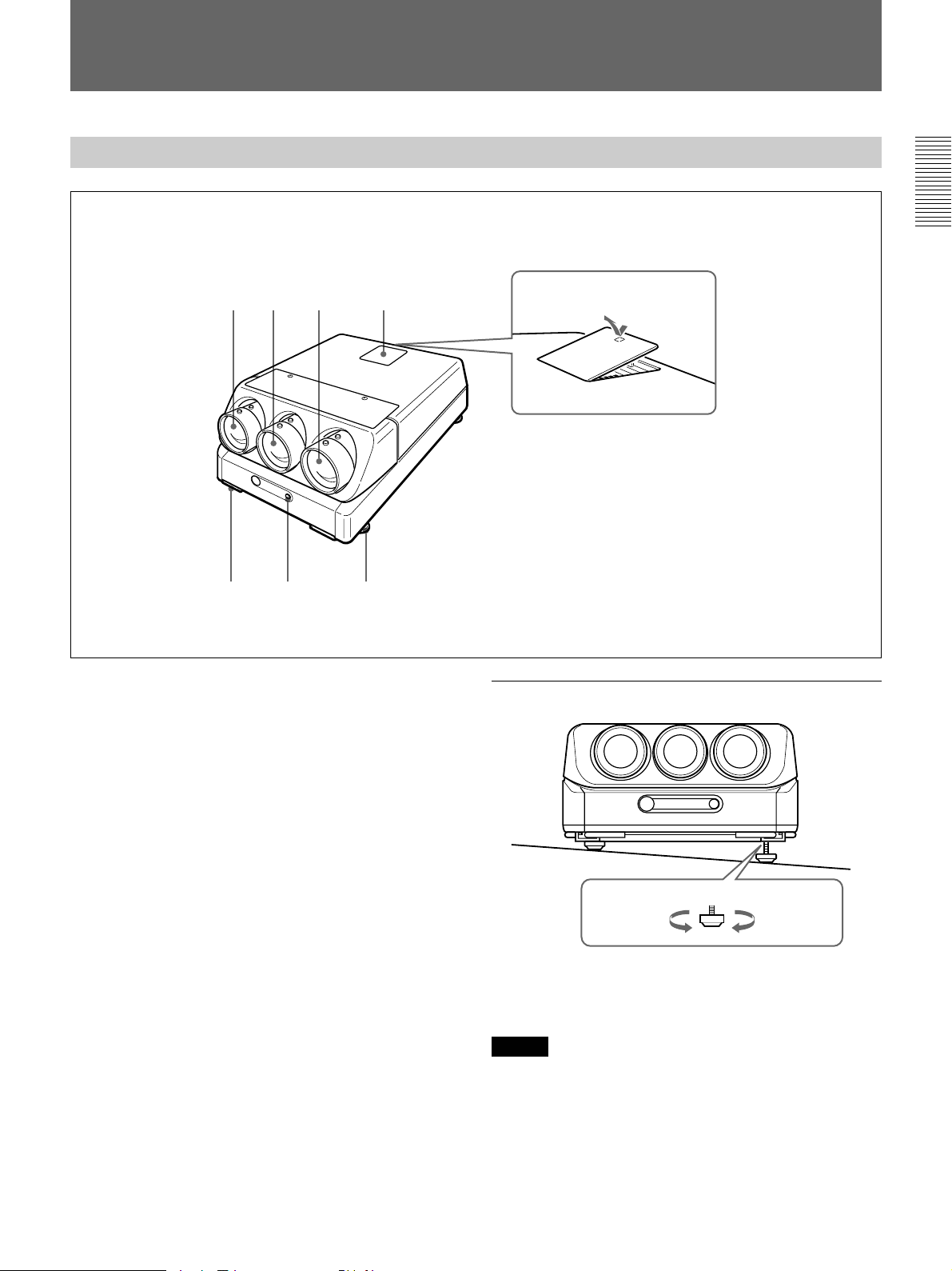
Front
1 Blue lens
2 Green lens
23 4
1
56 7
How to open the control
panel cover
How to use the adjusters
3 Red lens
4 Control panel cover
The control keys are inside the cover.
The locations and functions of the control keys are the
same as those of the remote control.
For details, see “Remote Control/Control Panel” on page
15.
5 Handles
Used for carrying the projector. The handles are
located on the front, rear, left and right sides.
6 Front remote control detector
7 Adjusters
Used to keep the projector level if it is installed on an
uneven surface (equipped with four adjusters).
To lower
the projector
To raise
the projector
While lifting the projector, turn the adjusters to adjust
the height so that the projector becomes level.
Note
Be careful not to let the projector down on your fingers.
11
Page 12

Location and Function of Controls
Using the handles
Pull out the front and rear handles or the side handles.
Putting away the handles
Push the handle release lever under each handle. The
handle is automatically retracted.
12
Page 13

Rear
1
REMOTE1
IN OUT
MODE
INPUT A
R
R-Y
P
G
Y
B
B-Y
P
SYNC
HD
VD
2
R
B
34
S VIDEO
TRIGGER
Y IN
C IN
IN
ABL LINK
OUT
IN
VIDEO
OUT
IN
OUT
CONTROL S
IN
PLUG IN
POWER
OUT
5
REMOTE
RS-422A
INDEX
67 8 9
1 Signal interface board attachment part (INPUT
B)
The IFB-40 Signal Interface Board is installed at the
factory. Other optional signal interface boards can be
attached to this section instead of the IFB-40.
Indicator (red): Lights up when the input of the IFB-
40 is selected.
REMOTE 1 IN connector (14-pin multi): When
connecting two projectors, connect to the REMOTE
1 OUT connector on the IFB-40 installed to another
projector.
REMOTE 1 OUT connector (14-pin multi): Connect
to the REMOTE 1 IN connector on the IFB-40.
MODE selector: Turn the control switch of the
MODE selector to the appropriate position according
to the length of the cable connected to the REMOTE
1 OUT connector.
Cable length
Type of cable
Position
up to 2 m
SIC-M-1
CCQ-2BRS
1
up to 10 m
SIC-M-5
CCQ-5BRS
CCQ-10BRS
2
up to 25 m
SIC-M-15
CCQ-25BRS
SIC-M-25
3
up to 50 m
SIC-M-50
CCQ-50BRS
4
!™
!£
POWER
STANDBY
IR
!¢
!∞
MAIN POWER
ONOFF
AC IN
100~120V 15A 250V
200V~240V T6.3A 250V
!º
!¡
2 INPUT A connectors (BNC type)
R/R-Y/P
R, G/Y, B/B-Y/PB, SYNC/HD, VD
connectors: Connect to the outputs of a computer or a
video camera. According to the connected
equipment, the RGB (R, G, B), component (R-Y, G,
B-Y) or HDTV (P
R, Y, PB) signal is selected.
3 S VIDEO IN/OUT connectors (VPH-G70Q/QM
only)
Y IN, C IN connectors (BNC type): Connects to the
Y and C video outputs of the video equipment.
S VIDEO IN/OUT connectors (4-pin, mini-DIN
type): Connects to the S video output or input of the
video equipment.
Note
The S VIDEO IN connector is disconnected when a cable is
connected to the Y/C IN connectors.
4 TRIGGER connector (minijack)
When the projector is turned on, 5 V is output and
when it is turned off, 0 V is output. However, the
connector is not used as the power source since the
power is not output.
13
Page 14

Location and Function of Controls
5 RS-422A REMOTE connector (D-sub 9-pin)
Used to expand the system connections using the RS422A interface.
Before using the connector, loosen the two screws to
remove the cap.
6 VIDEO IN/OUT connectors (VPH-G70Q/QM
only)
VIDEO IN connector (BNC type): Connects to the
composite video output of the video equipment.
VIDEO OUT connector (BNC type): Connects to the
composite video input of a color monitor.
7 ABL (Automatic Brightness Limiter) LINK IN/
OUT jacks (minijack)
When connecting multiple projectors, connects the
ABL LINK OUT jack to the ABL LINK IN jack on
another projector. You can synchronize the brightness
limiting point among the projectors, allowing to make
the whole screen brightness uniform.
8 CONTROL S jacks
IN/PLUG IN POWER (5 V) jack (stereo minijack):
Connects to the CONTROL S OUT jack of other
Sony equipment. Also connects to the CONTROL S
OUT jack of the supplied remote control with the
supplied remote control cable (stereo cable) to be
used as a wired remote control. In this case, this jack
supplys 5 V to the remote control as power source.
OUT jack (stereo minijack): Connects to the
CONTROL S IN jack of other Sony equipment.
!¡ MAIN POWER switch
!™ Error code window
An error code lights up when an operational error
occurs.
!£ POWER indicator
Lights in green when the power is turned on.
!¢ STANDBY indicator
Lights in orange when the MAIN POWER switch is
turned on. Once in the standby mode, you can turn the
projector on and off with the remote control.
!∞ Rear remote control detector
Note
When using this jack, the remote control detector on the
projector does not function.
9 INDEX NO. switches
When multiple projectors are connected, set the index
number of each projector.
To display the index number on the screen, press the
NORMAL key, and the ENTER key on the remote
control.
Note
If you set the index number to “00,” the projector does not
operate.
!º AC IN socket
Connect the supplied AC power cord.
14
Page 15

Remote Control/Control Panel
The locations and functions of the keys on the remote
control are the same as those on the control panel of
the projector. (Only the remote control is equipped
with the transmission indicator and the COMMAND
ON/OFF switch.)
The remote control may be used as a wired or wireless
remote control.
32
1
4
@£
@™
@¡
@º
!ª
!•
!¶
!§
LIGHT
MUTING
PIC
AUDIO OFF
LCD LENS CONTROL
ZOOM
NORMAL
PATTERN
VIDEO SELECT
A D
1
5
9
SHIFT
INPUT SELECT
VIDEO/S VIDEO
B
C
SWITCHER/INDEX
67
0(ALL)
SECOND
STATUS
ON
FOCUS
423
8
SWITCHER
INDEX
!∞
Note
The VOLUME +/– !¢, INPUT SELECT, C and D !¶,
AUDIO MUTING @¡ and LCD LENS CONTROL @™ keys
do not function with this projector.
COMMAND
OFF
RGB
SIZE
SHIFT
BLKG
5
ON
CENT
R
B
RESET
PICTURE CONTROL
6
MEMORY
7
BRIGHT
8
CONTR
OFF
9
POWER
ON
MENU
ENTER
POSITION
!º
!¡
!™
SHARP VOLUME
HUE COLOR
!£
!¢
1 LIGHT button
Illuminates the key indicators.
The key indicators turn off if you press the LIGHT
button again.
If you do not press any key for more than 30 seconds,
the indicators also turn off automatically.
If the COMMAND 6 switch on the remote control is
set to OFF, only the COMMAND switch is
illuminated.
When the remote control is connected to the
CONTROL S IN/PLUG IN POWER jack of the
projector via the remote control cable, the power is
supplied to the remote control from the projector.
2 Transmission indicator (only for the remote
control)
Lights each time you press a key. If it does not light,
replace the batteries with new ones.
3 STATUS ON/OFF key
Press OFF to eliminate the on-screen display.
Press ON to restore the on-screen display.
Note
The menus and warning messages appear even if the OFF
key is pressed.
15
Page 16

Location and Function of Controls
4 RGB SHIFT key
Enters the shift adjustment mode for the input signal.
Next adjust the position of the picture using the four
arrow keys. The picture shifts in the direction of the
arrow on the pressed key.
Press the MEMORY key 8 to store the adjusted value
and display the adjusted picture.
5 RGB SIZE key
Enters the size adjustment mode for the input signal.
Next adjust the size of the picture using the four arrow
keys.
B : to reduce horizontal size
b : to expand horizontal size
V : to expand vertical size
v : to reduce vertical size
Press the MEMORY key 8 to store the adjusted value
and display the adjusted picture.
6 COMMAND ON/OFF switch
No key on the remote control except the LIGHT button
1 function when this switch is set to OFF. This saves
the battery power.
7 CENT R/B keys
Enter the centering adjustment mode of the red and
blue.
R: Press to enter the red centering adjustment mode.
B: Press to enter the blue centering adjustment mode.
Perform the centering adjustment using the four arrow
keys.
8 MEMORY key
Stores various adjusted data into memory.
9 POWER ON/OFF keys
Turn on and off the projector when the MAIN
POWER switch on the projector is set to ON.
0 Menu operation keys
Used for various adjustment functions and for menu
operations.
MENU: Displays the main menu. Press it again to
turn off the menu.
Arrow keys: Adjusts the value or selects the item in
the menu.
ENTER: Stores the settings in the menu.
!¡ RESET key
Resets the adjusted levels to the factory preset or
service adjusted levels.
!™ POSITION +/– keys
Select the position to be adjusted on the screen in
blanking adjustment mode.
Also, set V SHIFT to WIDE or NARROW in the RGB
input signal’s SHIFT adjustment mode.
!£ PICTURE CONTROL keys
Adjust the picture conditions: CONTR (contrast),
BRIGHT (brightness), COLOR, HUE and SHARP
(sharpness).
!¢ VOLUME +/– keys
These keys do not function with this projector.
!∞ SWITCHER/INDEX select switch
Selects the function of the SWITCHER/INDEX keys.
Set to SWITCHER to select the input from the PC1271/1271M Signal Interface Switcher.
Set to INDEX to assign the index number of each
projector when multiple projectors are used.
!§ SWITCHER/INDEX keys
When the SWITCHER/INDEX select switch is set
to SWITCHER
When the PC-1271/1271M switcher (not supplied) is
connected to the projector, press a number key (1 – 8)
to select the input from the switcher. The number key
9 does not function.
To select the input from the second switcher (when the
SINGLE/SECOND/OTHER switch on the switcher is
set to SECOND), press a number key between 1 and 8
within two seconds after pressing the SECOND key.
When the SWITCHER/INDEX select switch is set
to INDEX
When multiple projectors are connected, select the
index number, which is set with the INDEX NO.
switch on the rear panel, of the projector to be
adjusted. Press a number key (1 – 9) to designate the
index number, then press the ENTER key. When
adjusting all the projectors simultaneously, press the 0
(ALL) key, then the ENTER key.
16
Page 17

!¶ INPUT SELECT keys
Select the input signal.
VIDEO: VPH-G70Q/QM The video or S video
signal input from the VIDEO IN or S VIDEO IN (or
Y/C IN) connectors
VPH-G70QMG Video or S video signal input from
the optional IFB-G70QMG Video Interface Board
(when installing the IFB-G70QMG to the projector)
SELECT VIDEO/S VIDEO: VPH-G70Q/QM
Selects the signal input from the VIDEO IN or S
VIDEO IN (or Y/C IN) connectors by pressing this
key after pressing the VIDEO key.
VPH-G70QMG Selects video or S video signal
input from the optional IFB-G70QMG (when
installing the IFB-G70QMG to the projector) after
pressing the VIDEO key.
A: The RGB, component or HDTV signal input from
the INPUT A connectors of the projector
B: The signal input from the INPUT B section when
the optional interface board other than the IFB-40 is
installed
C, D: These keys do not function with this projector.
Note
To switch the input signal from the INPUT A or INPUT B
to the S VIDEO IN (or Y/C IN) connectors, first press the
VIDEO key, then press the SELECT VIDEO/S VIDEO key.
!ª PATTERN key
Displays the internal test patterns of the projector.
Each press of the key displays CROSS HAIR,
HATCH (9 × 9), ME and COLOR BAR patterns,
sequentially.
@º NORMAL key
Erases the test pattern or cancels the various
adjustment modes.
@¡ MUTING keys
PIC (picture): Cuts off the picture. To restore the
picture, press the key again.
AUDIO: This key does not funcion with this
projector.
@™ LCD LENS CONTROL keys
These keys do not function with this projector.
@£ CONTROL S OUT jack (only for the remote
control)
Connects to the CONTROL S IN/PLUG IN POWER
jack on the projector for wired remote control
application.
!• BLKG (blanking) key
Enters the blanking adjustment mode.
You can adjust the blanking with the four arrow keys.
17
Page 18

Location and Function of Controls
Battery installation
1 Push to open the lid.
2 Install the three R6 (size AA) batteries (supplied)
with the correct polarity.
Be sure to install
the battery from
the ’ side.
Notes on wireless remote control operation
•Be sure that there is nothing to obstruct the infrared
beam between the remote control and the projector.
•The operation range is limited. The shorter the
distance between the remote control and the
projector, the wider the angle within which the
remote control can control the projector.
•The remote control detectors on the projector do not
operate when the remote control is being used as a
wired remote control. If you wish to use the remote
control as a wireless remote control, be sure to
remove the connecting cable from both the remote
control and the projector.
Connecting the remote control to the
projector
Rear of the projector
3 Replace the lid.
Notes on batteries
•Be careful that the battery orientation is correct when
inserting batteries.
•Do not mix old battery with new one, or different
types of batteries.
•If you do not intend to use the remote control for a
long time, remove the batteries to avoid damage from
battery leakage. If a battery has leaked, remove the
batteries, wipe the battery compartment dry and
replace the batteries with new ones.
CONTROL S
IN
PLUG IN
POWER
OUT
Remote control cable
(supplied)
CONTROL S IN
CONTROL
S OUT
18
Page 19

Projecting
1, 6
MAIN POWER
Projecting
u STANDBY indicator/
POWER indicator/
Rear remote control detector
Control panel (inside the cover)
ONOFF
Front remote control detector
Remote control
Point it toward the front
remote control detector.
4
SWITCHER/INDEX select switch
and number keys
LIGHT
MUTING
PIC ONAUDIO OFF
LCD LENS CONTROL
NORMAL
ZOOM
PATTERN
INPUT SELECT
VIDEO
SELECT
VIDEO/S VIDEO
ADBC
SWITCHER/INDEX
1423
5867
SECOND
9
0(ALL)
COMMAND
STATUS
ON
OFF
RGB
CENT
R
FOCUS
SHIFT
SHIFT
SHIFT
B
RESET
BLKG
PICTURE CONTROL
SHARP
SWITCHER
INDEX
MEMORY
BRIGHT
HUE
CONTR
COLOR
POWER
ONOFF
MENU
ENTER
POSITION
VOL
6
2
MENU key
5
1 Press the MAIN POWER switch on the rear of the projector.
The u STANDBY indicator lights in orange and the projector goes
into the standby mode.
2 Press the POWER ON key on the remote control or the control panel.
The POWER indicator lights in green.
A white screen with the message shown below (warming up screen)
appears on the screen. Make sure to allow the projector to warm up for
20 minutes after turning it on.
The message disappears temporarily in about 35 seconds, and will
appear subsequently for 5 seconds every 30 seconds.
INPUT-A
For optimum
performance
white screen will
remain for 20min.
For immediate use,
push [MENU] key.
Press the MENU key to cancel the warming up screen and see the
picture immediately after the projector is turned on if, for example, the
adjustment has been finished and warming up is not needed.
(continued)
19
Page 20

Projecting
3 Turn on the power of the connected equipment.
4 Select the input signal to be projected by pressing the INPUT SELECT
key.
VIDEO and SELECT keys: To project the signal input from the
equipment connected to the VIDEO IN or S VIDEO IN (or Y/C IN)
connectors. Select VIDEO or S VIDEO by pressing the VIDEO key,
then the SELECT key.
A: To project the RGB, component or the HDTV signal input from the
equipment connected to the INPUT A connectors.
B: To project the signal input from the equipment connected to the
optional interface board other than the IFB-40 installed to the
INPUT B section.
When the PC-1271/1271M Signal Interface Switcher is connected:
Set the SWITCHER/INDEX select switch to SWITCHER and then
select the input with the number keys 1 to 8. If two switchers are
connected, press the SECOND key and then the number key to
select the input from the second switcher.
Note
When you select the input signal connected to the INPUT A or INPUT B section,
be sure to select the correct signal in the SET SETTING menu. If an incorrect
signal is selected, picture may be distorted.
For details, see “The SET SETTING Menu” on page 33.
5 Adjust the picture.
For details, see “Adjusting the picture” on page 21.
6 To turn the power off, press the POWER OFF key on the remote
control or on the control panel of the projector, then set the MAIN
POWER switch on the projector to OFF.
To Press
Turn off the on-screen the STATUS OFF key.
display The menus and warning messages
appear even if the OFF key is pressed.
To restore the on-screen display, press
the STATUS ON key.
Cut off the picture the MUTING PIC key.
To restore the picture, press the
MUTING PIC key.
20
Note
To turn on the projector after the projector has been turned off due to a brief loss
of power, press the ON key on the remote commander, or turn off the MAIN
POWER switch so that the STANDBY indicator turns off and then turn on the
MAIN POWER switch.
Page 21

Adjusting the Picture
Adjust the picture for your preference. The adjustment data can be saved in
the memory.
1 Adjust with the PICTURE CONTROL +/– keys.
BRIGHT Brightness
CONTR Picture contrast
COLOR Color intensity
HUE Hue
SHARP Sharpness
The adjustment levels are digitally displayed with a range of MIN, 1, 2, ...
99, MAX.
BRIGHT: 50
Restoring the initial data
2 Press the MEMORY key to save the data.
Dynamic picture mode (only for the video or component input
pictures)
You can get high quality picture contrast by setting D.PICTURE to ON in
the PIC CTRL menu.
For details, see “PIC CTRL (Picture Control) menu” on page 28.
1 Press the PICTURE CONTROL key of the item which you want to
reset to the initial data.
2 Press the RESET key.
The selected item is reset to the initial data.
Notes
• The COLOR, SHARP and HUE keys do not function on the pictures input from
the RGB IN connectors.
• The HUE and COLOR keys do not function if the input signal is black and
white.
• The HUE key does not function with the PAL or SECAM color input source.
21
Page 22

Adjusting the Size And Shift of the Picture
The size and shift of the input picture can be adjusted to fit the screen.
SIZE adjustment
Adjust the picture size if it does not fit the screen.
1 Press the RGB SIZE key.
(Use the RGB SIZE key even for the signal other than RGB.)
SHIFT adjustment
2 Adjust the picture size with
the arrow keys.
V : The vertical size is
expanded.
v : The vertical size is
reduced.
b : The horizontal size is
expanded.
B : The horizontal size is
RGB SIZE ADJ
Hc: 80
Hf: 80
Vc: 80
Vf: 80
Picture
Screen
ADJ:
reduced.
3 Press the MEMORY key to save the adjustment data.
Resetting to the initial preset size
The picture size of the video signal can be reset to the initial preset size by
pressing the RESET key in RGB SIZE adjustment mode. (The picture size
of signals other than the video signal cannot be reset.)
If the picture needs to be shifted to fit the screen, adjust the position of the
picture.
22
1 Press the RGB SHIFT key.
(Use the RGB SHIFT key even for the signal other than RGB.)
2 Adjust the shift with the
arrow keys.
V :The picture is shifted
upward.
v :The picture is shifted
downward.
b :The picture is shifted
rightward.
B :The picture is shifted
leftward.
Note
When the RGB signal is input, the adjustable range of the vertical shift (V SHIFT)
can be set to WIDE or NARROW by pressing the POSITION +/– keys.
When the video signal is input, V SHIFT is automatically fixed to NARROW and
the adjustable range of the vertical shift will become narrower than that of the
RGB signal.
RGB SHIFT ADJ
V SHIFT:
NARROW
Hc: 50
Hf: 50
V :MIN
ADJ:
Screen
Picture
Page 23

Blanking adjustment
3 Press the MEMORY key to save the adjustment data.
Resetting to the initial preset position
The position of the picture of the video signal can be reset to the initial
preset position by pressing the RESET key in RGB SHIFT adjustment
mode. (The position of the picture of signals other than the video signal
cannot be reset.)
If the displayed picture is larger than the screen, cut off the excess parts.
1 Press the BLKG key.
2 Press the POSITION +/– keys to select the part to be adjusted.
• When you press the + key, the position cycles through the following
order:
TOP → BOTTOM → LEFT → RIGHT → TOP…
• When you press the – key, the position cycles in reverse order.
BLKG ADJ
TOP
T: 50
B: 50
L:MAX
R: 50
ADJ:
NEXT:
+ –
3 Adjust with the arrow keys.
• Press the V and v keys to adjust the TOP and BOTTOM positions.
• Press the B and b keys to adjust the LEFT and RIGHT positions.
4 Press the MEMORY key to save the adjustment data.
Note
When you connect multiple video input sources to the projector, such as when
using the switcher, adjust the picture size, picture shift and blanking for each input
connector.
23
Page 24

Centering Adjustment
The three colors, red, green and blue must converge for correct projection.
If they do not converge, centering adjustment is necessary.
Rear remote control detector
MAIN POWER switch (rear)
CENT R key
NORMAL
CENT B key
LIGHT
MUTING
PIC ONAUDIO OFF
LCD LENS CONTROL
ZOOM
SHIFT
PATTERN
INPUT SELECT
VIDEO
SELECT
VIDEO/S VIDEO
ADBC
SWITCHER/INDEX
1423
5867
SECOND
9
0(ALL)
STATUS
FOCUS
Control panel (inside the cover)
Front remote control detector
Remote control
Point it toward the front remote control detector.
ON key
COMMAND
ON
OFF
RGB
CENT
R
SHIFT
SHIFT
B
BLKG
RESET
PICTURE CONTROL
SHARP
SWITCHER
INDEX
MEMORY
BRIGHT
POWER
ONOFF
MENU
MEMORY key
Arrow keys (V, v, B, b)
ENTER
CONTR
POSITION
COLOR
HUE
VOL
1 Turn the projector on by switching on the MAIN POWER switch and
pressing the POWER ON key on the remote control.
2 Press the CENT R key.
The built-in CROSS HAIR test pattern appears and the red line will be
adjustable.
Blue
R CENT ADJ
R CENT ADJ
R CENT ADJ
Hc:128
Hc:128
Hf:128
Hc:128
Hf:128
Vc:118
Hf:128
Vc:118
Vf:130
Vc:118
Vf:130
Vf:130
Green Red
ADJ:
ADJ:
ADJ:
Red
Green
Blue
24
Page 25

3 Press the arrow keys to move the red line until the red and green lines
converge and become yellow.
The red line moves according to the direction of the arrow.
Blue Yellow
R CENT ADJ
R CENT ADJ
Yellow
Hc:128
Hc:128
Hf:128
Hf:128
Vc:118
Vc:118
Vf:130
Vf:130
ADJ:
ADJ:
Blue
4 Press the CENT B key.
The blue line will be adjustable.
Blue
B CENT ADJ
B CENT ADJ
Yellow
Yellow
Hc:128
Hc:128
Hf:128
Hf:128
Vc:118
Vc:118
Vf:130
Vf:130
ADJ:
ADJ:
Blue
5 Press the arrow keys to move the blue line until the blue and yellow
lines converge.
The blue line moves according to the direction of the arrow.
When all three color lines converge, the test pattern will become white.
B CENT ADJ
Hc:128
Hf:128
Vc:118
Vf:130
ADJ:
6 Press the MEMORY key.
The normal display is restored.
25
Page 26

INPUT-A
VIDEO:VIDEO
INPUT-A
INPUT-B
SWITCHER:SW'ER1-1
INPUT
SELECT
PIC
CTRL
INPUT
SETTING
SET
SETTING
INPUT
INFO.
SEL: SET:
ENTER
EXIT: MENU
Using the Menu
The projector is equipped with an on-screen menu for
making various adjustments and settings.
The language used in the menu can be changed to
French, German, Italian, Spanish, Japanese or Chinese.
For details, see “LANGUAGE” on page 34.
Basic Menu Operation
1 Press the MENU key.
The menu display appears.
The menu presently selected is highlighted in blue.
2 Use the v or V keys to select a menu, then press
the b key or the ENTER key.
The selected menu appears.
The setting items that are indicated in white
cannnot be selected.
To change the adjustment level
To increase the level, press the V or b key.
To decrease the level, press the v or B key.
Then press the ENTER key to store the adjusted level.
The original screen is restored.
CONTRAST: 80
To select an item
Use the v or V key to select an item in a pop-up menu,
then press the B key or the ENTER key. The selected
setting is stored and the pop-up menu disappears.
Pop-up menu
VIDEO MEMORY: OFF
INPUT
SELECT
1
CONTRAST 2
PIC
CTRL
BRIGHT 3
COLOR 4
INPUT
SETTING
HUE 5
SHARP
SET
SETTING
INPUT
INFO.
SEL: SET:
EXIT: MENU
ENTER
Menu items
VIDEO
VIDEO MEMORY:OFF
INPUT
SELECT
CONTRAST 80
PIC
CTRL
BRIGHT 50
COLOR 50
INPUT
SETTING
HUE 50
SHARP 50
SET
SETTING
INPUT
INFO.
Setting items
SEL: SET:
ENTER
RESET: RESET
EXIT: MENU
3 Use the v or V keys to select a setting item, then
press the b key or the ENTER key.
The adjustment menu or the setting menu (pop-up
menu) appears.
If there are two or more pages for a menu
The $ indication appears below the bottom item.
To go to the next page, move the cursor to the
bottom item with the v key, then press the v key.
To go back to the previous page, move the cursor
to the top item with the V key, then press the V key.
4 Make adjustment or setting on the menu.
For details on setting individual items, see the relevant
menu pages.
To clear the menu display
Press the MENU key.
The menu display also disappears automatically if no
key is pressed for about one minute.
To reset the settings that have been
adjusted
Press the RESET key. “Reset complete!” appears on
the screen and the settings appearing on the screen will
be reset to the factory preset or service adjusted levels.
Memory of the settings
The settings in the menus are automatically stored in
the projector memory. You can also store the settings
by pressing the MEMORY key.
26
Page 27

INPUT-A
VIDEO:VIDEO
INPUT-A
INPUT-B
SWITCHER:SW'ER1-1
INPUT
SELECT
PIC
CTRL
INPUT
SETTING
SET
SETTING
INPUT
INFO.
SEL: SET:
ENTER
EXIT: MENU
The INPUT SELECT Menu
INPUT-A
VIDEO:VIDEO
INPUT-A
INPUT-B
SWITCHER:SW'ER1-1
INPUT
SELECT
PIC
CTRL
INPUT
SETTING
SET
SETTING
INPUT
INFO.
SEL: SET:
ENTER
EXIT: MENU
Adjustments and settings using the menu
The INPUT SELECT menu is used for selecting the
input signal.
Items that can be selected are highlighted in green.
You cannot select the items indicated in white.
INPUT-A
VIDEO:VIDEO
INPUT
SELECT
INPUT-A
INPUT-B
PIC
CTRL
SWITCHER:SW'ER1-1
INPUT
SETTING
SET
SETTING
INPUT
INFO.
SEL: SET:
ENTER
EXIT: MENU
VIDEO
Selects signal input from the VIDEO IN or S VIDEO
IN (or Y/C IN) connectors (VPH-G70QMG: when
the IFB-G70QMG is installed to the projector).
DEO
VIDEO: VIDEO
INPUT
SELECT
INPUT- S-VIDEO
INPUT-
PIC
CTRL
SWITCHER:SW'ER1-1
INPUT
SETTING
SET
SETTING
INPUT
INFO.
SEL: SET:
EXIT: MENU
ENTER
Select VIDEO or S-VIDEO in the pop-up menu.
INPUT-A
INPUT-B
Selects signal input from the connectors on the signal
interface board (not supplied) installed to the INPUT B
section.
Notes
• When the PC-1271/1271M Signal Interface Switcher is
connected to the projector via the IFB-40 Signal Interface
Board installed to the INPUT B section, INPUT-B cannot
be selected.
• If the setting of INPUT B in the SET SETTING menu is
incorrect, the picture may be distorted.
For details, see page 33.
SWITCHER
When the PC-1271/1271M Signal Interface Switcher
is connected to the projector, selects signal input from
the Switcher.
INPUT-A
VIDEO:VIDEO
INPUT
SELECT
INPUT-A
INPUT-B
PIC
CTRL
SWITCHE SW ER 1-1
SW ER 1-2
INPUT
SETTING
SW ER 1-3
SW ER 1-4
SET
SETTING
INPUT
INFO.
SEL: SET:
EXIT: MENU
ENTER
Selects signal input from the INPUT A connectors.
Notes
• When the PC-1271/1271M Signal Interface Switcher is
connected to the INPUT A connectors using the 5BNC
cables, INPUT-A cannot be selected.
• If the setting of INPUT A in the SET SETTING menu is
incorrect, the picture may be distorted.
For details, see page 33.
You can select SW'ER1-1 to SW'ER2-8 in the pop-up
menu. They are always displayed in green even when
no signal is input.
Note
SWITCHER can be selected only when the IFB-40 Signal
Interface Board is installed to the INPUT B section, or when
5BNC MODE in the SET SETTING menu is set to ON.
27
Page 28

The PIC CTRL (Picture Control) Menu
The PIC CTRL menu is used for adjusting the picture.
Items that can be adjusted are highlighted in green.
You cannot select the items indicated in white.
Page 1
VIDEO
VIDEO MEMORY:OFF
INPUT
SELECT
CONTRAST 80
PIC
CTRL
BRIGHT 50
COLOR 50
INPUT
SETTING
HUE 50
SHARP 50
SET
SETTING
INPUT
INFO.
SEL: SET: ENTER
RESET: RESET
EXIT: MENU
Page 2
VIDEO
D.PICTURE:OFF
INPUT
SELECT
COLOR SYS:AUTO
SET UP:0
PIC
CTRL
INPUT
SETTING
SET
SETTING
INPUT
INFO.
SEL: SET:
ENTER
EXIT: MENU
CONTRAST
Adjusts the picture contrast.
CONTRAST: 80
The higher the setting, the greater the contrast.
The lower the setting, the lower the contrast.
BRIGHT
Adjusts the picture brightness.
BRIGHT: 50
The higher the setting, the brighter the picture.
The lower the setting, the darker the picture.
COLOR
Adjusts color intensity.
COLOR: 50
VIDEO MEMORY
Selects a memory number of the adjusted picture
levels.
VIDEO MEMORY: OFF
INPUT
SELECT
1
CONTRAST 2
PIC
CTRL
BRIGHT 3
COLOR 4
INPUT
SETTING
HUE 5
SHARP
SET
SETTING
INPUT
INFO.
SEL: SET:
EXIT: MENU
ENTER
Select a number from 1 to 10 in the pop-up menu, then
the picture levels that have been adjusted will be stored
in the number of the projector's memory.
If you want to use the data at the factory preset levels,
select OFF.
The items to be stored in the VIDEO MEMORY are
shown in the table of the memory architecture under
“Input memory” (except for the items, “clamp
position” and “registration” ).
28
The higher the setting, the greater the intensity.
The lower the setting, the lower the intensity.
HUE
Adjusts skin tones.
HUE: 50
At high settings, the picture becomes greenish.
At low settings, the picture becomes purplish.
SHARP
Adjusts the picture sharpness.
SHARP: 50
The higher the setting, the sharper the picture.
The lower the setting, the softer the picture.
Page 29

D. (Dynamic) PICTURE
INPUT
SELECT
PIC
CTRL
INPUT
SETTING
SET
SETTING
INPUT
INFO.
SEL: SET:
ENTER
EXIT: MENU
VIDEO
D.PICTURE:OFF
COLOR S O
SET UP: 0
7.5
SET UP
Emphasizes the black of the composite video, S video
(Y/C) or component signal.
VIDEO
D.PICTURE: ON
INPUT
SELECT
COLOR SYS: OFF
SET UP:0
PIC
CTRL
INPUT
SETTING
SET
SETTING
INPUT
INFO.
SEL: SET:
EXIT: MENU
ENTER
ON: Emphasizes the black to produce a bolder
“dynamic” picture.
OFF: Reproduces the dark portions of the picture
accurately, in accordance with the source signal.
COLOR SYS (System)
Selects the color system of the composite video or S
video (Y/C) signal.
VIDEO
D.PICTUR AUTO
INPUT
SELECT
COLOR SY NTSC3.58
SET UP:0 PAL
PIC
CTRL
SECAM
NTSC4.43
INPUT
SETTING
PAL-M
SET
SETTING
INPUT
INFO.
SEL: SET:
Normally, set to AUTO.
If the picture is distorted or colorless, select the color
system according to the input signal.
EXIT: MENU
ENTER
Changes the set up level (standard black level) to 0
IRE or 7.5 IRE according to the NTSC source signal.
0 IRE: Normally, set to this position.
7.5 IRE: Set to this position when the black color is
too light.
Input signals and adjustable/setting items
Input signal
3.58/
3.58/
Component
Y
Y
Y
N
Y
Y
N
N
HDTV
Y
Y
Y
Y
Y
N
N
N
RGB
Y
Y
N
N
N
N
N
N
Items
CONTRAST
BRIGHT
COLOR
HUE
SHARP
D. PICTURE
COLR SYS
SET UP
Video or S
video (Y/C)
Y
Y
Y
Y (NTSC
4.43
NTSC
system only)
Y
Y
Y
Y (NTSC
4.43
NTSC
system only)
Y: Adjustable/can be set
N: Not adjustable/can not be set
29
Page 30

The INPUT SETTING Menu
The INPUT SETTING menu is used to adjust the
input signal.
Items that can be adjusted are displayed in green.
You cannot select the items indicated in white.
Page 1
INPUT-A
COLOR TEMP:6500
INPUT
SELECT
CLAMP:AUTO
V SHIFT:WIDE
PIC
CTRL
SYNC SEL:AUTO
COMPONENT FORMAT:
INPUT
SETTING
SMPTE/EBU-N10
SYNC OSC:1
SET
SETTING
INPUT
INFO.
SEL: SET:
ENTER
EXIT: MENU
Page 2
INPUT-A
RGB SIZE
INPUT
SELECT
RGB SHIFT
BLKG
PIC
CTRL
INPUT
SETTING
SET
SETTING
INPUT
INFO.
SEL: SET:
ENTER
EXIT: MENU
COLOR TEMP (Temperature)
Selects the appropriate color temperature according to
your application and the input source signal.
COLOR TEMP 9300
INPUT
SELECT
CLAMP:AUTO 6500
V SHIFT:WI 5400
PIC/AU
CTRL
SYNC SEL:A 3200
COMPONENT PRESET
INPUT
SETTING
SMPTE
SYNC OSC:1
SET
SETTING
INPUT
INFO.
SEL: SET:
ENTER
EXIT: MENU
CLAMP
Corrects the luminance of the input picture.
INPUT-A
COLOR
INPUT
SELECT
CLAMP AUTO
V SHI SonG
PIC/AU
CTRL
SYNC H/C
COMPO HP
INPUT
SETTING
TRI-LEVEL S
SYNC
SET
SETTING
INPUT
INFO.
SEL: SET:
CLAMP is used as a standard for setting the black
level of a picture correctly. The standard position of
the clamp depends on the kind of sync signal being
used. Normally, the projector CPU judges the signal
and sets the position automatically. However, the CPU
can misjudge the signal because of noise. If the
luminance of the picture seems to be incorrect, the
clamp position may need to be changed.
ENTER
EXIT: MENU
30
AUTO: Automatic setting mode. Normally set to this
position.
SonG: Set to this position if the black seems too light
or greenish.
H/C: Set to this position if the picture is too dark or
luminance is unstable.
HP: If the luminance is still incorrect after changing
to the SonG or H/C position, set to this position
and perform the H-SHIFT adjustment.
TRI-LEVEL S: Set to this position if the picture is
dark when using the tri-level sync.
Note
If the luminance is still incorrect after changing the clamp
setting, check the input signal and the connections.
Page 31

V (Vertical) SHIFT
COMPONENT FORMAT
Sets the adjustable range of the vertical shift of the
input signal.
INPUT-A
COLOR TEMP:6500
INPUT
SELECT
CLAMP:AU
V SHIFT: WIDE
PIC/AU
CTRL
SYNC SEL NARROW
COMPONEN
INPUT
SETTING
SMPTE/EBU-N10
SYNC OSC:1
SET
SETTING
INPUT
INFO.
SEL: SET:
ENTER
EXIT: MENU
WIDE: Normally, set to this position (factory preset).
NARROW: When some signal such as a
superimposed signal with unstable vertical sync.
signal is input, the picture may be distorted
vertically. In this case, set to this position.
Adjustable range in the lower direction will
become narrow.
Note
When the video, S video or component signal is input, V
SHIFT is fixed to NARROW.
Note
SYNC SEL (select)
Selects the sync. signal.
Selects the format of the component input signal.
INPUT-A
COLOR TEMP:6500
INPUT
SELECT
CLAMP:AUTO
V SHIFT:WIDE
PIC/AU
CTRL
SYN
COM SMPTE/EBU-N10
INPUT
SETTING
BETACAM7.5
SYN
SET
SETTING
INPUT
INFO.
SEL: SET:
ENTER
EXIT: MENU
SMPTE/EBU-N10: Set to this position if the input
signal is the SMPTE or EBU-N10 format
component signal.
BETACAM7.5: Set to this position if the input
signal is the Betacam format component signal.
SYNC OSC (oscillation)
Normally, set to 1. When synchronization is distorted
according to the type of the input signal, set to 2.
INPUT-A
COLOR TEMP:6500
INPUT
SELECT
CLAMP:AUTO
V SHIFT:WIDE
PIC/AU
CTRL
SYNC SEL:AUTO
COMPONENT FORMAT:
INPUT
SETTING
SMPT U-N10
SYNC OSC: 1
SET
SETTING
2
INPUT
INFO.
SEL: SET:
ENTER
EXIT: MENU
INPUT-A
COLOR TEMP:6500
INPUT
SELECT
CLAMP:AUTO
V SHIFT:W
PIC/AU
CTRL
SYNC SEL: AUTO
COMPONENT SonG
INPUT
SETTING
SMPT H/C V
SYNC OSC:
SET
SETTING
INPUT
INFO.
SEL: SET:
ENTER
EXIT: MENU
AUTO: Automatic setting mode. Normally set to this
position.
SonG: Set to this position if you project the picture
using the sync on G signal.
H/C V: Set to this position if you project the picture
using the external sync signal.
When an HDTV signal is input
You can select the items below instead of the above
items.
INT: Set to this position when using the internal sync
signal.
EXT (C): Set to this position when using the external
composite sync signal.
EXT (HV): Set to this position when using the
external horizontal/vertical sync signal.
RGB SIZE
Adjusts the picture size of the input signal.
RGB SIZE ADJ
Hc:128
Hf:128
Vc:128
Vf:128
Use the B or b key to adjust the horizontal size.
Use the V or v key to adjust the vertical size.
Hc and Hf show the size adjustment levels for the
horizontal direction and Vc and Vf show those for the
vertical direction. The higher the setting level, the
greater the picture size.
ADJ:
SET:
ENTER
EXIT: MENU
31
Page 32

The INPUT SETTING Menu
RGB SHIFT
Adjusts the picture position of the input signal.
RGB SHIFT ADJ
V SHIFT:
WIDE
Hc:128
Hf:128
V :128
ADJ:
SET:
ENTER
EXIT: MENU
Use the B or b key to adjust the horizontal position.
Use the V or v key to adjust the vertical position.
Hc and Hf show the shift adjustment levels for the
horizontal direction and V shows the level for the
vertical direction.
BLKG (Blanking)
Cuts off the excess parts if the displayed picture is
larger than the screen.
Input signals and adjustable/setting items
Input signal
Items
Video or
S video (Y/C)
COLOR TEMP
CLAMP
V SHIFT
SYNC SEL
COMPONENT
Y
N
N
N
N
FORMAT
SYNC OSC
RGB SIZE
RGB SHIFT
BLKG
Y
Y
Y
Y
Y: Adjustable/can be set
N: Not adjustable/can not be set
Component
Y
N
N
N
Y
Y
Y
Y
Y
HDTV
Y
Y
Y
Y
N
Y
Y
Y
Y
RGB
Y
Y
Y
Y
N
Y
Y
Y
Y
INPUT-A
RGB SIZE
INPUT
SELECT
RGB
BLKG TOP
PIC
CTRL
BOTTOM
LEFT
INPUT
SETTING
RIGHT
SET
SETTING
INPUT
INFO.
SEL: SET:
ENTER
EXIT: MENU
Select the part to be adjusted among TOP, BOTTOM,
LEFT and RIGHT, then press the b key or the ENTER
key to display the blanking adjustment screen.
BLKG ADJ
TOP
T:MAX
B:MIN
L:MIN
R:MAX
ADJ:
SET:
ENTER
NEXT:
+ –
EXIT:
MENU
Use the V or v key to adjust the TOP and BOTTOM
parts.
Use the B or b key to adjust the LEFT and RIGHT
parts.
32
Page 33

The SET SETTING Menu
INPUT-A
STATUS:ON
PIC.MUTING: ON
INPUT-A:RGB OFF
INPUT-B:RGB
LANGUAGE:ENGLISH
ABG MODE:ON
INPUT
SELECT
PIC
CTRL
INPUT
SETTING
SET
SETTING
INPUT
INFO.
SEL: SET:
ENTER
EXIT: MENU
INPUT-A
STATUS:
PIC.MUT RGB
INPUT-A COMPONENT
INPUT-B HDTV-YPBPR
LANGUAG HDTV-GBR
ABG MOD VIDEO
S-VIDEO
INPUT
SELECT
PIC
CTRL
INPUT
SETTING
SET
SETTING
INPUT
INFO.
SEL: SET:
ENTER
EXIT: MENU
INPUT-A
STATUS:ON
PIC.MUT
INPUT-A RGB
INPUT-B COMPONENT
LANGUAG HDTV-YPBPR
ABG MOD HDTV-GBR
INPUT
SELECT
PIC
CTRL
INPUT
SETTING
SET
SETTING
INPUT
INFO.
SEL: SET:
ENTER
EXIT: MENU
The SET SETTING menu is used for changing the
default settings of the projector.
Items that can be adjusted are highlighted in green.
You cannot select the items indicated in white.
Page 1
INPUT-A
STATUS:ON
INPUT
SELECT
PIC.MUTING:OFF
INPUT-A:RGB
PIC
CTRL
INPUT-B:RGB
LANGUAGE:ENGLISH
INPUT
SETTING
ABG MODE:OFF
SET
SETTING
INPUT
INFO.
SEL: SET:
ENTER
EXIT: MENU
Page 2
INPUT-A
SCREEN SEL:1
INPUT
SELECT
SIRCS RECEIVER:
FRONT&REAR
PIC
CTRL
POWER SAVING:OFF
PATTERN:OFF
INPUT
SETTING
INDEX:01
5BNC MODE:OFF
SET
SETTING
INPUT
INFO.
SEL: SET:
ENTER
EXIT: MENU
PIC. (picture) MUTING
Set to ON to cut off the picture.
When set to ON, “PIC MUTING” appears on the
screen.
INPUT A
Selects the signal input from the INPUT A connectors.
RGB: Inputs the RGB signal.
COMPONENT: Inputs the component signal.
HDTV-YPBPR: Inputs the HDTV (YPBPR) signal.
HDTV-GBR: Inputs the HDTV (GBR) signal.
STATUS
Selects the on-screen display mode.
A
STATUS: ON
INPUT
SELECT
PIC.MUT OFF
INPUT-A ALL OFF
PIC
CTRL
INPUT-B
LANGUAGE:ENGLISH
INPUT
SETTING
ABG MODE:ON
SET
SETTING
INPUT
INFO.
SEL: SET:
ON: Shows all of the on-screen displays.
OFF: Turns off the on-screen displays except for
“NO INPUT,” “PIC MUTING,” warning
messages and menu displays.
ALL OFF: Turns off all of the on-screen displays
except for warning messages and menu displays.
INPUT B
Selects the signal input from the IFB-12 Signal
Interface Board (not supplied) installed to the INPUT
B section.
ENTER
EXIT: MENU
RGB: Inputs the RGB signal.
COMPONENT: Inputs the component signal.
HDTV-YPBPR: Inputs the HDTV (YP
BPR) signal.
HDTV-GBR: Inputs the HDTV (GBR) signal.
VIDEO: Inputs the composite video signal.
S-VIDEO: Inputs the S video signal.
Note
When a signal interface board other than the IFB-12 is
installed, the menu items cannot be selected.
33
Page 34

The SET SETTING Menu
INPUT-A
SCREEN SEL:1
SIRCS RECEIVER:
FRONT
POWER SAVING: ON
PATTERN:OFF OFF
INDEX:01
5BNC MODE:OFF
INPUT
SELECT
PIC
CTRL
INPUT
SETTING
SET
SETTING
INPUT
INFO.
SEL: SET:
ENTER
EXIT: MENU
LANGUAGE
Selects the language used in the on-screen displays.
STATUS:O ENGLISH
INPUT
SELECT
PIC.MUTI FRANCAIS
INPUT-A: DEUTSCH
PIC
CTRL
INPUT-B: ITALIANO
LANGUAGE ESPANOL
INPUT
SETTING
ABG MODE
SET
SETTING
INPUT
INFO.
SEL: SET:
ENTER
EXIT: MENU
Available languages are: English, French, German,
Italian, Spanish, Japanese and Chinese.
ABG (Automatic Background) MODE
Normally, set to ON (factory setting). Cutoff
luminance will be set to a certain level. Set to OFF if
you want to erase the horizontal luminescent line for
cutoff level detection that may appear at the upper part
of the picture.
INPUT-A
STATUS:ON
INPUT
SELECT
PIC.MUTING:OFF
INPUT-A:RGB
PIC
CTRL
INPUT-B:RGB
LANGUAGE:
INPUT
SETTING
ABG MODE: ON
OFF
SET
SETTING
INPUT
INFO.
SEL: SET:
ENTER
EXIT: MENU
SIRCS RECEIVER
Selects the remote control detectors on the front and
rear of the projector, if the wireless remote control
does not operate correctly due to the influence of a
fluorescent lamp, etc.
INPUT-A
SCREEN
INPUT
SELECT
SIRCS FRONT&REAR
FRONT
PIC
CTRL
POWER REAR
PATTER
INPUT
SETTING
INDEX:01
5BNC MODE:OFF
SET
SETTING
INPUT
INFO.
SEL: SET:
ENTER
EXIT: MENU
FRONT & REAR: Activates both the front and rear
detectors.
FRONT: Activates the front detector only.
REAR: Activates the rear detector only.
POWER SAVING
When set to ON, the projector goes into the power
saving mode if no signal is input for 10 minutes. The
screen enters cut-off mode. The power saving mode is
canceled when a signal is input or whenever any key is
pressed.
Note
When ABG MODE is set to OFF, the black level of the
white balance may change.
SCREEN SEL (Select)
Selects the screen to be used.
T-A
SCREEN SEL: 1
INPUT
SELECT
SIRCS RECEI 2
FRO AR
PIC
CTRL
POWER SAVING:OFF
PATTERN:OFF
INPUT
SETTING
INDEX:01
5BNC MODE:OFF
SET
SETTING
INPUT
INFO.
SEL: SET:
1: Bead screen
2: Mat screen
34
ENTER
EXIT: MENU
Page 35

PATTERN
Selects the type of the test pattern to be displayed.
INPUT-A
SCRE
INPUT
SELECT
SIRC OFF
CROSS HAIR
PIC
CTRL
POWER HATCH(9X9)
PATTE ME
INPUT
SETTING
INDEX COLOR BAR
5BNC
SET
SETTING
INPUT
INFO.
SEL: SET:
ENTER
EXIT: MENU
Selectable patterns are: CROSS HAIR, HATCH (9 ×
9), ME and COLOR BAR.
Set to OFF when you do not want to display a test
pattern.
INDEX (Index number)
Indicates the index number of the projector set with the
INDEX NO. switches on the rear panel.
INPUT-A
SCREEN SEL:1
INPUT
SELECT
SIRCS RECEIVER:
FRONT&REAR
PIC
CTRL
POWER SAVING:OFF
PATTERN:OFF
INPUT
SETTING
INDEX:01
5BNC MODE:OFF
SET
SETTING
INPUT
INFO.
SEL: SET:
ENTER
EXIT: MENU
5BNC MODE
Set to ON when you connect the MONITOR OUT
connector on the PC-1271/1271M Signal Interface
Switcher to the INPUT A connectors with the 5BNC
cables.
INPUT-A
SCREEN SEL:1
INPUT
SELECT
SIRCS RECEIVER:
FRONT&REAR
PIC
CTRL
POWER SAVING:OFF
PATTERN:OFF
INPUT
SETTING
INDEX:01
5BNC MODE: ON
SET
SETTING
OFF
INPUT
INFO.
SEL: SET:
ENTER
EXIT: MENU
35
Page 36

The INPUT INFO (Information) Menu
The INPUT INFO menu displays the information on
the current input signal.
INPUT-A
fH: 31.4KHz
INPUT
SELECT
fV: 59.9Hz
H/C-SYNC:POS
PIC
CTRL
V-SYNC:POS
SonG:NEG
INPUT
SETTING
INPUT SIGNAL:RGB
SET
SETTING
INPUT MEMORY No.02
No.11
INPUT
INFO.
SET:
SEL:
ENTER
n
EXIT: MENU
fH (Horizontal frequency)
Indicates the horizontal frequency of the input signal.
This indication is not an absolute value, but is only
used as a reference.
fV (Vertical frequency)
Indicates the vertical frequency of the input signal.
This indication is not an absolute value, but is only
used as a reference.
H/C (Horizontal/Composite)-SYNC
Indicates the polarity of the horizontal or composite
sync. signal. When the picture is being projected using
this type of sync signal, the POS (NEG) is displayed in
green. When the picture is being projected without
using this type of sync signal, the POS (NEG) is
displayed in white.
POS: The polarity of the sync signal is positive.
NEG: The polarity of the sync signal is negative.
– – –: No sync signal is input.
SonG (Sync on Green)
Indicates the polarity of the sync. on Green. When the
picture is being projected using this type of sync.
signal, the NEG is displayed in green. When the
picture is being projected without using this type of
sync. signal, the NEG is displayed in white.
NEG: The polarity of the sync. signal is negative.
– – –: No sync. signal is input.
INPUT SIGNAL
Displays the type of current input signal.
NTSC 3.58: NTSC
PAL: PAL input signal
SECAM: SECAM input signal
NTSC 4.43: NTSC
PAL-M: PAL-M input signal
B/W: Black and white input signal
Y/C: S video input signal
RGB: RGB input signal
COMPONENT: Component input signal
HDTV YPBPR: HDTV YP
HDTV GBR: HDTV GBR input signal
IDTV: IDTV input signal from the optional PC-
1271/1271M Signal Interface Switcher via the
optional IFB-3000 Interface Board installed to the
PC-1271/1271M.
3.58 input signal
4.43 input signal
BPR input signal
V (Vertical)-SYNC
Indicates the polarity of the vertical or the composite
sync. signal.
When the picture is being projected using this type of
sync. signal, the POS (NEG) is displayed in green.
When the picture is being projected without using this
type of sync. signal, the POS (NEG) is displayed in
white.
POS: The polarity of the sync. signal is positive.
NEG: The polarity of the sync. signal is negative.
– – –: No sync. signal is input.
36
Page 37

SEL: SET:
ENTER
EXIT: MENU
INT IDTV
INT.IDTV: ON
V APERTUR OFF
SEL: SET:
ENTER
EXIT: MENU
INT IDTV
INT.IDTV:OFF
V APERTURE: LOW
MID
HIGH
The OPTION Menu
INPUT MEMORY NO.
The upper number is the memory number of the data
automatically loaded when the current signal is input.
The lower number is the new memory number in
which the adjustment data of the current input signal is
stored. The existent memory number is displayed in
green, and a new memory number in yellow.
By default ten basic data are preset in the following
memory numbers.
Memory
number
00
01
02
03
04
05
06
07
08
09
Preset signal
frequencies
fH
15.7 kHz
24.8 kHz
31.5 kHz
48.3 kHz
64.0 kHz
75.0 kHz
93.7 kHz
106.3 kHz
31.5 kHz
33.8 kHz
fV
60 Hz
56 Hz
60 Hz
60 Hz
60 Hz
60 Hz
75 Hz
85 Hz
60 Hz
60 Hz
Types of the
input signal
Video (NTSC
RGB
RGB
RGB
RGB
RGB
RGB
RGB
IDTV (NTSC
HDTV (Y/P
B/PR)
3.58)
3.58)
The OPTION menu is used when installing the EXBDS10 Extension Board to the projector.
INPUT-A
INT IDTV
OPTION
SEL: SET:
ENTER
EXIT: MENU
INT. (internal) IDTV
Set to ON to project the video, S video, component or
RGB (15 kHz) signal at double density.
FREQUENCY SENSITIVITY
Selects the sensitivity to the frequency deviation of the
input signal, with which the INPUT MEMORY data is
switched automatically. This item can be selected only
for RGB input signals.
Press the b key or the ENTER key on the INPUT
INFO menu, and the INPUT MEM. OPTION menu
appears. Press the b key or the ENTER key again to
show the frequency sensitivity options.
INPUT-A
INPUT MEM.OPTION
FREQUENCY HIGH
SENSITIVIT LOW
HIGH: This position is selected at the factory.
LOW: Set to this position if the input signal is
unstable or flickers. This phenomenon may
appear during variable speed playback by the
VCR, etc.
SEL: SET:
V. (vertical) APERTURE
Corrects the sharpness in the vertical direction. You
can set the sharpness to the LOW, MID (middle) or
HIGH level.
ENTER
EXIT: MENU
37
Page 38

Installation Examples
Installation and the preliminary adjustments should be carried out by
Qualified Sony Personnel. This projector allows you to project the picture
between 60 and 300 inches.
Installation 1 Floor Installation Using Front Projection Flat Screen
Be sure that the projector is level to the floor.
Wall
G
E
A
D
Center of the green lens
B
Screen size
(inches)
A (Vsize) 914 1067 1219 1372 1524 1829 2286 2743 3048 3810 4572
B (Hcent) 725 794 865 935 1005 1145 1356 1566 1707 2058 2410
C (Width)
D (TD) 1727 1990 2256 2522 2787 3316 4117 4916 5446 6778 8117
E (Xlens) 1668 1921 2177 2434 2689 3200 3972 4743 5254 6539 7831
F (Lhole) 1888 2141 2397 2654 2910 3420 4193 4964 5475 6760 8051
G (Lmax) 2575 2828 3084 3341 3596 4107 4879 5650 6161 7446 8738
H (Lfront) 1627 1880 2136 2393 2648 3159 3931 4702 5213 6498 7790
60 70 80 90 100 120 150 180 200 250 300
(36) (42 1/8) (48) (54 1/8) (60) (72 1/8) (90) (108) (120) (150) (180)
(28 5/8) (31 3/8) (34 1/8) (36 7/8) (39 5/8) (45 1/8) (53 1/2) (61 3/4) (67 1/4) (81 1/8) (95)
(68) (78 3/8) (88 7/8) (99 3/8) (109 3/4) (130 5/8) (162 1/8) (193 5/8) (214 1/2) (266 7/8) (319 5/8)
(65 3/4) (75 3/4) (85 3/4) (92 1/4) (105 7/8) (126) (156 1/2) (186 3/4) (206 7/8) (257 1/2) (308 3/8)
(74 3/8) (84 3/8) (94 3/8) (104 1/2) (114 5/8) (134 3/4) (165 1/8) (195 1/2) (215 5/8) (266 1/4) (317)
(101 1/2) (111 3/8) (121 1/2) (131 5/8) (141 5/8) (161 3/4) (192 1/8) (222 1/2) (242 5/8) (293 1/4) (344 1/8)
(64 1/8) (74 1/8) (84 1/8) (94 1/4) (104 3/8) (124 3/8) (154 7/8) (185 1/8) (205 1/4) (255 7/8) (306 3/4)
Center of the screen
C
B: Difference in height between the projector’s bottom surface and the center of the screen
E: Horizontal distance between the center of the screen and the center of the green lens
F: Horizontal distance between the center of the screen and the standard hole for installation
Tolerances
15.2˚
274.8 (10 7/8)
H
F
B: ±5%
Other measurements: 0% to +5%
The distances in gray are the factory preset settings. Unit:mm (inches)
28a)32
(1 1/8) (1 5/16) (1 5/16)
b)
32
c)
Standard hole
for installation
Floor
a) Sony VPS-80FH and VPS-100FH
b) Sony VPS-100FM
c) Sony VPS-120FH and VPS-120FM
38
Page 39

Installation Examples
Installation 2 Ceiling Installation Using Front Projection Flat Screen
Use the PSS-70 projector suspension support (not supplied).
Installation/connection examples
F’
E
H
B
A
Screen size
(inches)
A (Vsize) 914 1067 1219 1372 1524 1829 2286 2743 3048 3810 4572
B (Hcent) 822 891 961 1032 1102 1241 1452 1663 1804 2155 2507
(32 3/8) (35 1/8) (37 7/8) (40 3/4) (43 1/2) (48 7/8) (57 1/4) (65 1/2) (71 1/8) (84 7/8) (98 3/4)
D (TD) 1727 1990 2256 2522 2787 3316 4117 4916 5446 6778 8117
E (Xlens) 1668 1921 2177 2434 2689 3200 3972 4743 5254 6539 7831
(65 3/4) (75 3/4) (85 3/4) (92 1/4) (105 7/8) (126 1/4) (156 1/2) (186 3/4) (206 7/8) (257 1/2) (308 3/8)
F’ (Lpss) 1990 2243 2500 2756 3012 3523 4295 5066 5577 6862 8154
(78 3/8) (88 3/8) (98 1/2) (108 5/8) (118 5/8) (138 3/4) (169 1/8) (199 1/2) (219 5/8) (270 1/4) (321 1/8)
G (Lmax) 2575 2828 3084 3341 3596 4107 4879 5650 6161 7446 8738
(101 1/2) (111 3/8) (121 1/2) (131 5/8) (141 5/8) (161 3/4) (192 1/8) (222 1/2) (242 5/8) (293 1/4) (312 1/8)
H (Lfront) 1627 1880 2136 2393 2648 3159 3931 4702 5213 6498 7790
(64 1/8) (74 1/8) (84 1/8) (94 1/4) (104 3/8) (124 3/8) (154 7/8) (185 1/8) (205 1/4) (255 7/8) (304 3/4)
Center of
the screen
Wall
60 70 80 90 100 120 150 180 200 250 300
(36) (42 1/8) (48) (54 1/8) (60) (72 1/8) (90) (108) (120) (150) (180)
(68) (78 3/8) (88 7/8) (99 3/8) (109 3/4) (130 5/8) (162 1/8) (193 5/8) (214 1/2) (266 7/8) (319 5/8)
15.2˚
D
G
E: Horizontal distance between the center of the screen and the center of the green lens
Tolerances
B: ±5%
Other measurements: 0% to +5%
372 (14 3/4)
274.8
(10 7/8)
Center of the green lens
Rotation axis of
the PSS-70
Ceiling
Unit:mm (inches)
39
Page 40

Connection Examples
When making connections:
•Before connecting any cables, make sure that each
piece of equipment to be connected is turned off.
•Use cables appropriate for the equipment to be
connected.
•A loose connection may cause hum or noise.
•When disconnecting a cable, pull it out from the plug;
not the cable itself.
•Also refer to the instruction manual of the equipment
to be connected.
Connecting Directly to the Projector
Use the IFU-1271/1271M Signal Interface Unit.
Connecting a BNC connector:
2 Twist to the right.
1 Align the pins with the pin holes and
push the plug into the socket.
Rear
IFU-1271/1271M
to RGB input
Computer
SYNC/HD
IFB-12
to RGB output
*IFB-G70QMG Video Interface Board
R
G
B
VD
REMOTE1
IN OUT
INPUT A
S VIDEO
R
R-Y
P
R
G
Y
B
B-Y
B
P
MODE
SYNC
HD
VD
TRIGGER
Y IN
C IN
IN
ABL LINK
OUT
IN
VIDEO
OUT
IN
OUT
VIDEO OUT
to video
to video input
to RGB output
Color
output
monitor
to RGB input
Color
monitor
REMOTE
RS-422A
CONTROL S
IN
INDEX
PLUG IN
POWER
OUT
Video equipment
MAIN POWER
ONOFF
AC IN
100~120V 15A 250V
200V~240V T6.3A 250V
S VIDEO INVIDEO IN
AC IN
AC power cord
(supplied)
to S Video
output
to a wall outlet
*VPH-G70QMG: connections when the optional
IFB-G70QMG Video Interface Board is installed.
40
Setting up
Set INPUT-A in the SET SETTING menu to RGB.
For details, see “The SET SETTING Menu” on page 33.
Page 41

Using the Signal Interface Switcher
When you connect the PC-1271/1271M Signal Interface Switcher (not
supplied) to the IFB-40 Signal Interface Board (installed on the projector
by default), you can connect easily various input sources.
IFB-40 Signal Interface Board
*IFB-G70QMG Video
Interface Board
REMOTE1
IN OUT
SIC-M or CCQ-BRS
connecting cable
PC-1271/1271M
Switcher
IN
to
REMOTE 1
OUT
R
to RGB output
INPUT A
S VIDEO
R
R-Y
R
P
G
Y
B
B-Y
B
P
MODE
SYNC
HD
VD
TRIGGER
Y IN
C IN
IN
ABL LINK
OUT
IN
VIDEO
OUT
IN
OUT
VIDEO IN
G
B
SYNC/HD
to video output
CONTROL S
OUT
VD
Rear
REMOTE
RS-422A
AC IN
MAIN POWER
ONOFF
AC IN
100~120V 15A 250V
200V~240V T6.3A 250V
AC power cord
IN
INDEX
PLUG IN
POWER
S VIDEO IN
(supplied)
to S Video output
to a wall outlet
Video
equipment
Computer
Video
equipment
*VPH-G70QMG: connections when the optional
IFB-G70QMG Video Interface Board is installed.
Choose the appropriate cable from the following table.
1 m 2 m 5 m 10 m 15 m 25 m 50 m
— CCQ-2BRS CCQ-5BRS CCQ-10BRS — CCQ-25BRS CCQ-50BRS
SIC-M-1 — SIC-M-5 — SIC-M-15 SIC-M-25 SIC-M-50
Notes
• Insert the female and male plugs of the SIC-M or CCQ-BRS cable correctly.
• You can extend the SIC-M or CCQ-BRS cable up to 50 m.
• The video signal input to the signal interface board installed to the INPUT B
section should not exceed 70 MHz. When projecting the video signal which
exceeds 70 MHz, connect the signal source to the INPUT A connectors using the
5BNC cables.
Setting up
•Set INPUT-A in the SET SETTING menu to RGB.
For details, see “The SET SETTING Menu” on page 33.
•Set the SINGLE/SECOND/OTHER select switch on the switcher to
SINGLE.
41
Page 42

Troubleshooting
If the projector appears to be operating erratically, try to diagnose and correct the problem using the following
guide. If the problem still persists, consult with qualified Sony personnel.
Symptom Cause Remedy
The power does not turn on.
The power turns on and
immediately turns off.
Picture does not appear.
Picture is too dark.
Picture is distorted.
Error code “10” appears and
the projector cannot accept
any other command than
channel selection.
The MAIN POWER switch is turned off.
There may be an internal problem.
If no menu appears, external signal and/
or sync is not input correctly.
If menu appears with no input, sync
connection is not correct.
If no menu appears with no input, there
may be an internal problem.
Contrast is set to minimum.
Clamp setting is not correct.
The input signal is not selected correctly.
The input signal is unstable.
Press the MAIN POWER switch on the projector
(see page 19).
Check the error code in the error code window on
the rear of the projector and consult with qualified
personnel.
Check the input signal and sync in the INPUT
INFO menu and connect them correctly (see page
36).
Check SYNC SEL in the INPUT SETTING menu
and connect the sync correctly, if necessary (see
page 30).
Consult with qualified personnel.
Adjust the contrast with the CONTR + key (see page
21).
Change the clamp setting in the INPUT SETTING
menu (see page 30).
Select a correct signal in the INPUT A or INPUT B
option in the SET SETTING menu (see page 33).
Check the input signal.
42
Page 43

Specifications
Maintenance / Other
Optical characteristics
Projection system
3 picture tubes, 3 lenses, horizontal
inline system
Picture tube 8-inch high luminance,
electromagnetic focus tubes, with
coolant sealed
Projection lens HACC (High-resolution Aspherical
and Color Corrected) multicoating
lenses
Projected picture size
Factory-adjusted to 120 inches
(diagonal measure)
Range: 60 to 300 inches (diagonal
measure) adjustable
Light output ANSI lumen
6500°K)
240 lm (fH: 110 kHz, fV: 50 Hz)
200 lm (fH: 15 kHz, fV: 60 Hz)
Peak white: 1200 lm
All white: 350 lm
1)
(color temperature:
INPUT A BNC type (5)
Electrical characteristics
Color system NTSC, PAL, SECAM, NTSC4.43,
and PAL-M switched automatically
Resolution 700 TV lines (video input)
1100 TV lines (HDTV input)
1700 × 1200 pixels (RGB input at fH:
75 kHz, fV: 60 Hz)
RGB inputs Horizontal frequency: 15 kHz to 110
kHz
Vertical frequency: 38 Hz to 150 Hz
Test signal Various test pattern generators
incorporated
Input/Output
VIDEO (VPH-G70Q/QM only)
VIDEO IN: BNC type (1)
Composite video input, 1 Vp-p ±
2 dB, sync negative, 75 ohms
terminated
VIDEO OUT: BNC type (1)
Loop-through output of VIDEO IN
S VIDEO (VPH-G70Q/QM only)
Y IN: BNC type (1)
Luminance signal, 1 Vp-p ± 2 dB,
..........................................................................................................................................................................................................
1) ANSI lumen is a measuring method of American National Standard IT 7.215.
sync negative, 75 ohms terminated
C IN: BNC type (1)
Chrominance signal, 1 Vp-p ± 2
dB, sync negative, 75 ohms
terminated
S VIDEO IN: 4-pin mini-DIN (1)
Y (luminance) signal: 1 Vp-p
± 2 dB, sync negative, 75 ohms
terminated
C (luminance) signal: 0.286 Vp-p
± 2 dB, 75 ohms terminated
(NTSC)
0.3 Vp-p ± 2 dB, 75 ohms
terminated (PAL)
S VIDEO OUT: 4-pin mini-DIN (1)
Loop-through output of S VIDEO
IN
Analog RGB/Component:
R/R-Y: 0.7 Vp-p ± 2 dB,
75 ohms terminated, positive
G: 0.7 Vp-p ± 2 dB, 75 ohms
terminated, positive
G with sync/Y: 1 Vp-p ± 2 dB, 75
ohms terminated, sync negative
B/B-Y: 0.7 Vp-p ± 2 dB, 75 ohms
terminated, positive
SYNC/HD: Composite sync: 0.6–8
Vp-p high impedance, sync
positive/negative
Vertical sync width: wider than
horizontal scanning interval
(2H)
VD:Vertical sync: 0.6–8 Vp-p high
impedance, sync positive/
negative
Vertical sync width: Wider than
horizontal scanning interval
(2H)
HDTV Y/P
Y: 1 Vp-p ± 2 dB, 75 ohms
terminated,
Tri-level sync: ±0.3 Vp-p,
Bi-level sync: 0.3 Vp-p
B/PR: 0.35 Vp-p ± 2 dB,
P
75 ohms terminated
HDTV GBR:
G with sync: 1 Vp-p ± 2 dB,
75 ohms terminated,
Tri-level sync: ±0.3 Vp-p,
Bi-level sync: 0.3 Vp-p
B/R: 0.7 Vp-p ± 2 dB,
75 ohms terminated
B/PR:
43
Page 44

Specifications
CONTROL S IN/PLUG IN POWER
stereo minijack type (1)
5 Vp-p, plug in power, DC 5 V
maximum output 60 mA
OUT
stereo minijack type (1)
loop-through output of CONTROL
S IN
TRIGGER Minijack type (1)
POWER ON: DC 5 V,
output impedance 4.7 kilohms
POWER OFF: 0 V
ABL LINK IN: minijack (1)
OUT: minijack (1)
RS-422A D-sub 9-pin type (1)
General
Dimensions 695 × 358 × 948 mm (27 3/8 × 14
Mass Approx. 83 kg (182 lb 16 oz)
Power requirements
Power consumption
Operating temperature
Operating humidity
Storage temperature
Storage humidity
Supplied Accessories
3
/32 × 37 5/16 inches) (w/h/d)
VPH-G70Q: AC 120 V, 50/60 Hz
VPH-G70QM/QMG: AC 220–240 V,
50/60 Hz
VPH-G70Q: Max. 750 W (Standby
mode: 7 W)
VPH-G70QM/QMG: Max. 720 W
(Standby mode: 7 W)
0°C to 40°C (32°F to 104°F)
35% to 85% (no condensation)
–20°C to 60°C (–4°F to 140°F)
10% to 90%
Remote control RM-PJ1000 (1)
size AA (R6) batteries (3)
Remote control cable (15 m (49.5
feet) long) (1)
AC Power cord (1)
Power plug adaptor (1)
Lens cap (3)
Lens cap for magnetic focus
adjustment (1)
Operating Instructions (1)
Acquired safety regulations
VPH-G70Q:
UL1950, CSA950
FCC class A, IC class A
DHHS, DNHW
VPH-G70QM/QMG:
TÜV (EN60950), PTB
CE-Marking, C-Tick Mark
Optional accessories
Signal Interface Switcher PC-1271/1271M
Signal Interface Unit IFU-1271/1271M
Projector Suspension Support PSS-70
Interface Board IFB-12/20/21/30/1000
Signal Interface Cable
SIC-10/20A/20B/20C/21/22/23/24/24A/24B/25/
26/26A/30/31/M1/5/15/25/50
CCQ-BRS2/5/10/25/50
Extension Board EXB-DS10 (Internal IDTV board)
Remote Commander RM-PJM800
Remote Control Unit RM-PJ10
Mouse Receiver Unit RM-PJ20
Signal Adaptor ADP-10/20
HD D-sub 15-pin to 5 BNC cable SMF-400
HD D-sub 15-pin to HD D-sub 15-pin cable SMF-401
9-pin remote cable for RS-422A RCC-5G/10G/30G
Screen
VPS-80FH (80" flat)
VPS-100FH (100" flat)
VPS-120FH (120" flat)
VPS-80FM (80" flat, powered)
VPS-100FM (100" flat, powered)
VPS-120FM (120" flat, powered)
Some items may not be available in certain areas. For
details, please consult your nearest Sony office.
44
Page 45

Pin assignment
REMOTE 1 connectors on IFB-40
S VIDEO connector (4-pin, mini-DIN)
(VPH-G70Q/QM only)
Chrominance
GND
Luminance
GND
RS-422A connector (D-sub 9-pin, female)
Pin No. Signal
1 GND Ground
2 TX Receive
3 RX Transmit
4 GND Ground
5 Not used
6 GND Ground
7 TX Receive
8 RX Transmit
9 GND Ground
IN (male)
12
345
6789
10 11 12
13 14
OUT (female)
21
543
9876
12 11 10
14 13
Pin No. Signal Signal level
1 GND Ground
2 HD/C. sync 1 Vp-p ± 3 dB
3 SIRCS 5 Vp-p ± 1 dB
4 N.C. Non connection
5 GND (SIRCS) Ground
6 B/C B: 0.7 Vp-p ± 3 dB, 75-ohm
C (NTSC): 0.286 Vp-p ± 3 dB, 75-ohm
C (PAL): 0.3 Vp-p ± 3 dB, 75-ohm
7 GND (B.R) Ground
8 GND (G) Ground
9 G/Y G: 0.7 Vp-p (sync-on-green: 1 Vp-p)
±3 dB, 75-ohm
Y: 1 Vp-p ± 3 dB, 75-ohm
10 RGB/Video 5V / 0V
11 R/C. video R: 0.7 Vp-p ± 3 dB, 75-ohm
C. Video: 1 Vp-p ± 3 dB, 75-ohm
12 C. Video/YC 5V / 0V
13 Audio 500 mVrms, output impedance 1 kohm
14 V. sync 1 Vp-p ± 3 dB, 75-ohm
45
Page 46

Specifications
Index
A
Ajusters 11
Adjusting
the blanking 23
the centering 24
the picture 21
the size/position of the picture 22
B
Battery
installation 18
notes 18
Blanking adjustment 23
C
Carrying the projector 12
Clamp setting 30
Connecting
remote control to the projector 18
directly to the projector 40
using the signal interface switcher
41
Control panel
location and function of controls
15
Cutting off the picture 20
D, E
Dynamic picture 21, 29
F
Frequency sensitivity 37
G, H
Handles 12
N
Notes
for wireless remote control operation
18
on batteries 18
O
Optional accessories 44
P, Q
Pin assignment 45
Precautions 8
Projecting the picture 19
R
Remote control
location and function of controls
15
notes 18
Resetting
picture settings to the initial preset levels
21
the size/position to the initial preset
levels 22, 23
S
Supplied accessories 44
T
Turning off the on-screen display 20
U, V
Using
the handles 12
I, J, K, L
Index 35
Initialization screen 19
Input signal selection 20
Installation
ceiling installation 39
diagrams 38, 39
floor installation 38
M
Menu
INPUT INFO menu 36
INPUT MEM. OPTION menu 37
INPUT SELECT menu 27
INPUT SETTING menu 30
Operation 26
OPTION menu 37
PIC CTRL menu 28
SET SETTING menu 33
46
W
Warming up screen 19
Page 47

47
Page 48

Sony Corporation Printed in Japan
 Loading...