

Page 1
3-858-829-15 (2)
Multiscan Pr ojector
Operating Instructions
Mode d’emploi
Manual de instrucciones
EN
F
E
VPH-D50Q
VPH-D50QM
©1996 by Sony Corporation
Page 2
English
WARNING
To prevent fire or shock hazard, do not
expose the unit to rain or moisture.
To avoid electrical shock, do not open the
cabinet. Refer servicing to qualified
personnel only.
This symbol is intended to alert the
user to the presence of uninsulated
“dangerous voltage” within the
product’s enclosure that may be of
sufficient magnitude to constitute a risk
of electric shock to persons.
This symbol is intended to alert the
user to the presence of important
operating and maintenance (servicing)
instructions in the literature
accompanying the appliance.
For the customers in the USA
This equipment has been tested and found to comply with
the limits for a Class B digital device, pursuant to Part 15 of
the FCC Rules. These limits are designed to provide
reasonable protection against harmful interference in a
residential installation. This equipment generates, uses, and
can radiate radio frequency energy and, if not installed and
used in accordance with the instructions, may cause
harmful interference to radio communications. However,
there is no guarantee that interference wll not occur in a
particular installation. If this equipment does cause harmful
interference to radio or television reception, which can be
determined by turning the equipment off and on, the user is
encouraged to try to correct the interference by one or more
of the following measures:
– Reorient or relocate the receiving antenna.
– Increase the separation between the equipment and
receiver.
– Connect the equipment into an outlet on a circuit different
from that to which the receiver is connected.
– Consult the dealer or an experienced radio/TV technician
for help.
You are cautioned that any changes or modifications not
expressly approved in this manual could void your authority
to operate this equipment.
For the customers in Canada
This Class B digital apparatus meets all requirements of the
Canadian Interference-Causing Equipment Regulations.
For the customers in the United Kingdom
WARNING
THIS APPARATUS MUST BE EARTHED
IMPORTANT
This wires in this mains lead are coloured in accordance
with the following code:
Green-and-Yellow: Earth
Blue: Neutral
Brown: Live
As the colours of the wires in the mains lead of this
apparatus may not correspond with the coloured markings
identifying the terminals in your plug proceed as follows:
The wire which is coloured green-and-yellow must be
connected to the terminal in the plug which is marked by the
letter E or by the safety earth symbol Y or coloured green
or green-and-yellow.
The wire which is coloured blue must be connected to the
terminal which is marked with the letter N or coloured black.
The wire which is coloured brown must be connected to the
terminal which is marked with the letter L or coloured red.
Voor de klanten in Nederland
• Dit apparaat bevat een Li-ion batterij voor memory back-
up.
• De batterij voor memory back-up van het geheugen is
bevestigd op IC2016 van plaat A.
• Raadpleeg uw leverancier over de verwijdering van de
batterij op het moment dat u het apparaat bij einde
levensduur afdankt.
• Gooi de batterij niet weg, maar lever hem in als KCA.
• Bij dit product zijn batterijen geleverd.
Wanneer deze leeg zijn, moet u ze niet
weggooien maar inleveren als KCA.
The socket-outlet should be installed near the equipment
and be easily accessible.
2 (EN)
Page 3

Table of Contents
Overview
Projecting
Adjustments and settings
using the menu
Precautions................................................................ 4 (EN)
Features ..................................................................... 6 (EN)
Location and Function of Controls ......................... 7 (EN)
Projecting................................................................. 17 (EN)
Adjusting the Picture.............................................. 19 (EN)
Adjusting the Size and Shift of the Picture .......... 20 (EN)
Centering Adjustment............................................. 22 (EN)
Using the Menu ....................................................... 24 (EN)
The INPUT SELECT Menu ...................................... 25 (EN)
The PIC CTRL (Picture Control) Menu .................. 26 (EN)
EN
English
Installation/connection
examples
Maintenance
Other
The INPUT SETTING Menu..................................... 28 (EN)
The SET SETTING Menu......................................... 31 (EN)
The INPUT INFO (Information) Menu..................... 34 (EN)
The OPTION Menu................................................... 35 (EN)
Installation Examples ............................................. 36 (EN)
Installation 1 Floor Installation Using Front Projection
Flat Screen......................................................... 36 (EN)
Installation 2 Ceiling Installation Using Front Projection
Flat Screen......................................................... 37 (EN)
Connection Examples............................................. 38 (EN)
Connecting Directly to the Projector...................... 38 (EN)
Using the Signal Interface Switcher....................... 39 (EN)
Troubleshooting...................................................... 40 (EN)
Specifications.......................................................... 41 (EN)
Index......................................................................... 44 (EN)
3 (EN)
Page 4

Precautions
On safety
On installation
•Check that the operating voltage of your unit is identical with the voltage
of your local power supply. If voltage adaptation is required, consult with
qualified Sony personnel.
•Should any liquid or solid object fall into the cabinet, unplug the unit and
have it checked by qualified personnel before operating it further.
•Unplug the unit from the wall outlet or set the MAIN POWER switch to
OFF if it is not to be used for several days.
•To disconnect the cord, pull it out by the plug. Never pull the cord itself.
•The wall outlet should be near the unit and easily accessible.
•The unit is not disconnected from the AC power source (mains) as long
as it is connected to the wall outlet, even if the unit itself has been turned
off.
•When the projector is mounted on the ceiling, the Sony PSS-70 Projector
Suspension Support must be used for installation. Read the installation
manual of the PSS-70 carefully, since the ceiling should be reinforced for
safety.
•Allow adequate air circulation to prevent internal heat build-up. Do not
place the unit on surfaces (rugs, blankets, etc.) or near materials (curtains,
draperies) that may block the ventilation holes. Leave space of more than
30 cm (12 inches) between the wall and the projector. Be aware that room
heat rises to the ceiling; check that the temperature near the installation
location is not excessive.
•Do not install the unit in a location near heat sources such as radiators or
air ducts, or in a place subject to direct sunlight, excessive dust or
humidity, mechanical vibration or shock.
•To avoid moisture condensation, do not install the unit in a location
where the temperature may rise rapidly.
•Fans are installed inside the projector to prevent internal heat build-up.
The fans produce a humming noise when the power is switched on, which
is normal. Should the noise sound abnormal, please consult qualified
Sony personnel.
On illumination
4 (EN)
•To obtain the best picture, the front of the screen should not be exposed
to direct lighting or sunlight.
•Ceiling-mounted spot lighting is recommended. Use a cover over
fluorescent lamps to avoid lowering the contrast ratio.
•Cover any windows that face the screen with opaque draperies.
•It is desirable to install the projector in a room where floor and walls are
not of light-reflecting material. If the floor and walls are of reflecting
material, it is recommended that the carpet and wall paper be changed to
a dark color.
Page 5

On operation
On cleaning
CRT burns
Overview
To turn on the projector after the projector has been turned off due to a
brief loss of power, press the POWER ON key on the remote control, or
turn off the MAIN POWER switch so that the STANDBY indicator turns
off and then turn on the MAIN POWER switch.
•To keep the cabinet looking new, periodically clean it with a soft cloth.
Stubborn stains may be removed with a cloth lightly dampened with a
mild detergent solution. Never use strong solvents, such as thinner,
benzene, or abrasive cleansers, since these will damage the cabinet.
•Avoid touching the lens. To remove dust on the lens, use a soft dry cloth.
Do not use a damp cloth, detergent solution, or thinner.
On repacking
When a static picture of a VCR or a computer is displayed for more than
about an hour, a CRT burn may result. This means that an after-image
impression of the static picture remains on the screen even after the picture
has changed. If it is necessary to display the same static picture for more
than an hour, we recommend that you set the CONTR (contrast) control to
the lowest setting.
Also, when a picture of different size is displayed beyond a certain length
of time, an after-image impression of the frame of the smaller picture may
be burnt on the screen (such as displaying a 16:9 wide size picture on a 4:3
screen). To avoid this, we recommend that you use the same picture size
when possible. However, if it is necessary to use a different picture size,
set the CONTR (contrast) control and the BRT (brightness) control of the
smaller picture to the lowest setting possible. This will minimize the risk
of creating an after-image impression.
If the CRT burns, it must be replaced. In this case, refer to the warranty
provided with this unit. Consult your Sony dealer or Qualified Service
Personnel.
Save the original shipping carton and packing material; they will come in
handy if you ever have to ship your unit. For maximum protection, repack
your unit as it was originally packed at the factory.
5 (EN)
Page 6

Features
Multiscan projector
This projector accepts and automatically detects horizontal scanning
frequencies between 15 kHz and 64 kHz and vertical scanning frequencies
between 38 Hz and 150 Hz.
In addition to high-resolution pictures from computers, you can also
project pictures from teletext decoders, VCRs and video cameras.
High resolution and brightness
A newly developed 7-inch CRT and a hybrid Sony HACC (Highresolution Aspherical and Color Corrected) lens are incorporated in the
projector to provide a sharp and bright high-quality picture with the high
resolution of 1280 × 1024 pixels and the high light output of 160 lumen.
Easy operation—remote control, on-screen display
Adjustments such as input selection, picture control and centering
adjustment can be remotely controlled from both the front and rear of the
projector with the supplied remote control. You can also use the control as
a wired remote control by connecting it to the projector with the supplied
remote control cable.
Compatible with various color systems
NTSC, PAL, SECAM, NTSC4.431) or PAL-M color system can be selected
automatically or manually.
Flexible setup
You can project a 60- to 250-inch picture (120-inch standard) with this
projector. The projector can be set up on the floor or ceiling, for front or
rear projection to suit the installation location, surrounding illumination,
usage, etc.
Illuminated control panel/remote control keys
The key names on the remote control and the control panel of the projector
can be illuminated for easy access in a dark place by pressing the LIGHT
button.
..........................................................................................................................................................................................................
1) NTSC4.43 is the color system used when playing back a video recorded on NTSC on a NTSC4.43 system VCR.
6 (EN)
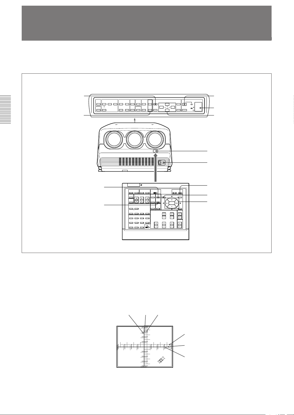
Page 7
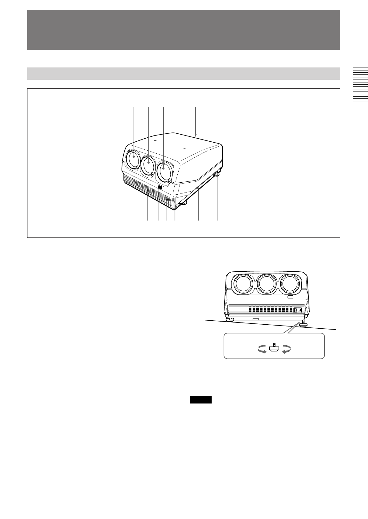
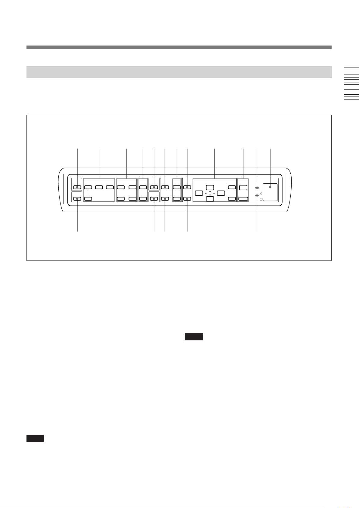
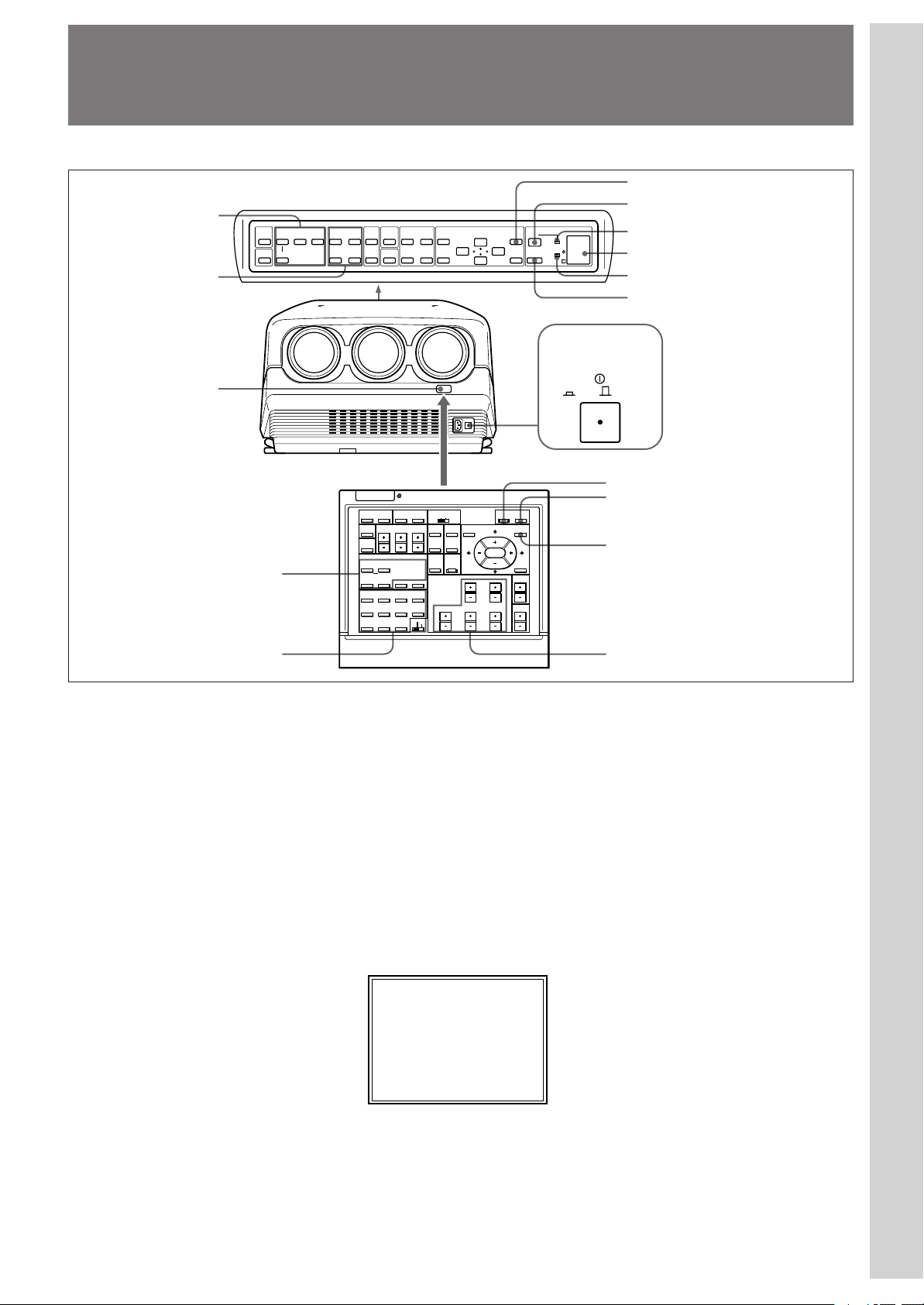
Location and Function of Controls
Front
23 4
1
5
1 Blue lens
2 Green lens
3 Red lens
4 Control panel
For details, see “Control Panel” on page 9 (EN).
5 Front ventilation hole
6 Front remote control detector
7 AC IN socket
8 MAIN POWER switch
9 Handles
Used for carrying the projector. The handles are
located on the right and left sides.
0 Adjusters
Used to keep the projector level if it is installed on an
uneven surface (equipped with four adjusters).
9876
!º
How to use the adjusters
To lower the
projector
While lifting the projector, turn the adjusters to adjust
the height so that the projector becomes level.
Note
Be careful not to let the projector down on your fingers.
To raise
the projector
7 (EN)
Page 8
Location and Function of Controls
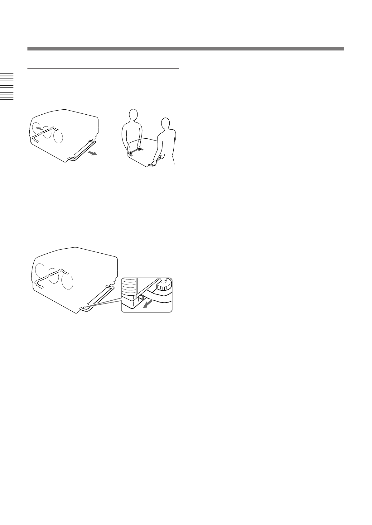
Using the handles
Pull out the side handles.
Putting away the handles
Pull the handle release lever under each handle
towards you. The handle is automatically retracted.
8 (EN)
Page 9
Control Panel
12 345678 9 !º!¡!™
The keys with the same names as those on the remote control have the
same functions. The functions of the keys and switches that are not on the
control panel can be selected with the menu operation.
LIGHT
NORMAL
INPUT SELECT
VIDEO
SELECT
VIDEO/S VIDEO
BA
PICTURE CONTROL
BRIGHT-CONTR
-
STATUS
ON
++
OFF
--
MUTING
PIO
BLKG
RGB
SIZE R
SHIFT
!£ !¢ !∞ !§ !¶
1 LIGHT key
Illuminates the key indicators on the control panel. The
key indicators turn off if you press the LIGHT key
again.
If you do not press any key for more than 30 seconds,
the indicators also turn off automatically.
2 INPUT SELECT keys
Select the input signal.
VIDEO: The video or S video signal input from the
VIDEO IN or S VIDEO IN (or Y/C IN) connectors
SELECT VIDEO/S VIDEO: Selects the signal input
from the VIDEO IN or S VIDEO IN (or Y/C IN)
connectors by pressing this key after pressing the
VIDEO key.
A: The RGB, component or HDTV signal input from
the INPUT A connectors
B: The signal input from the INPUT B section when
the optional interface board other than the IFB-40 is
installed
Note
To switch the input signal from the INPUT A or INPUT B
to the S VIDEO IN (or Y/C IN) connectors, first press the
VIDEO key, then press the SELECT VIDEO/S VIDEO key.
CENT
MEMORY
B
RESET
MENU
ENTER
POWER
ON
OFF
STANDBY
IR
3 PICTURE CONTROL keys
Adjust the picture conditions: CONTR (contrast) and
BRIGHT (brightness).
4 STATUS ON/OFF key
Press OFF to eliminate the on-screen display.
Press ON to restore the on-screen display.
Note
The menus and warning messages appear even if the OFF
key is pressed.
5 MUTING PIC key
Cuts off the picture. To restore the picture, press the
key again.
9 (EN)
Page 10

Location and Function of Controls
6 RGB SIZE key
Enters the size adjustment mode for the input signal.
Next adjust the size of the picture using the four arrow
keys.
B : to reduce horizontal size
b : to expand horizontal size
V : to expand vertical size
v : to reduce vertical size
Press the MEMORY key 8 to store the adjusted value
and display the adjusted picture.
7 CENT R/B keys
Enter the centering adjustment mode of the red and
blue.
R: Press to enter the red centering adjustment mode.
B: Press to enter the blue centering adjustment mode.
Perform the centering adjustment using the four arrow
keys.
8 MEMORY key
Stores various adjusted data into memory.
9 Menu operation keys
Used for various adjustment functions and for menu
operations.
MENU: Displays the main menu. Press it again to
turn off the menu.
Arrow keys: Adjusts the value or selects the item in
the menu.
ENTER: Stores the settings in the menu.
!∞ RGB SHIFT key
Enters the shift adjustment mode for the input signal.
Next adjust the position of the picture using the four
arrow keys. The picture shifts in the direction of the
arrow on the pressed key.
Press the MEMORY key 8 to store the adjusted value
and display the adjusted picture.
!§ RESET key
Resets the adjusted levels to the factory preset or service
adjusted levels.
!¶ u STANDBY indicator
Lights in orange when the projector is turned on with the
MAIN POWER switch.
!º POWER ON/OFF keys
Turn on and off the projector when the MAIN
POWER switch on the projector is set to ON.
!¡ POWER ON indicator
Lights in green when the power of the projector is on.
!™ Error code window/rear remote control detector
Indicates an error code when an operational error
occurs.
!£ NORMAL key
Erases the test pattern or cancels the various
adjustment modes.
!¢ BLKG (blanking) key
Enters the blanking adjustment mode.
You can adjust the blanking with the four arrow keys.
10 (EN)
Page 11
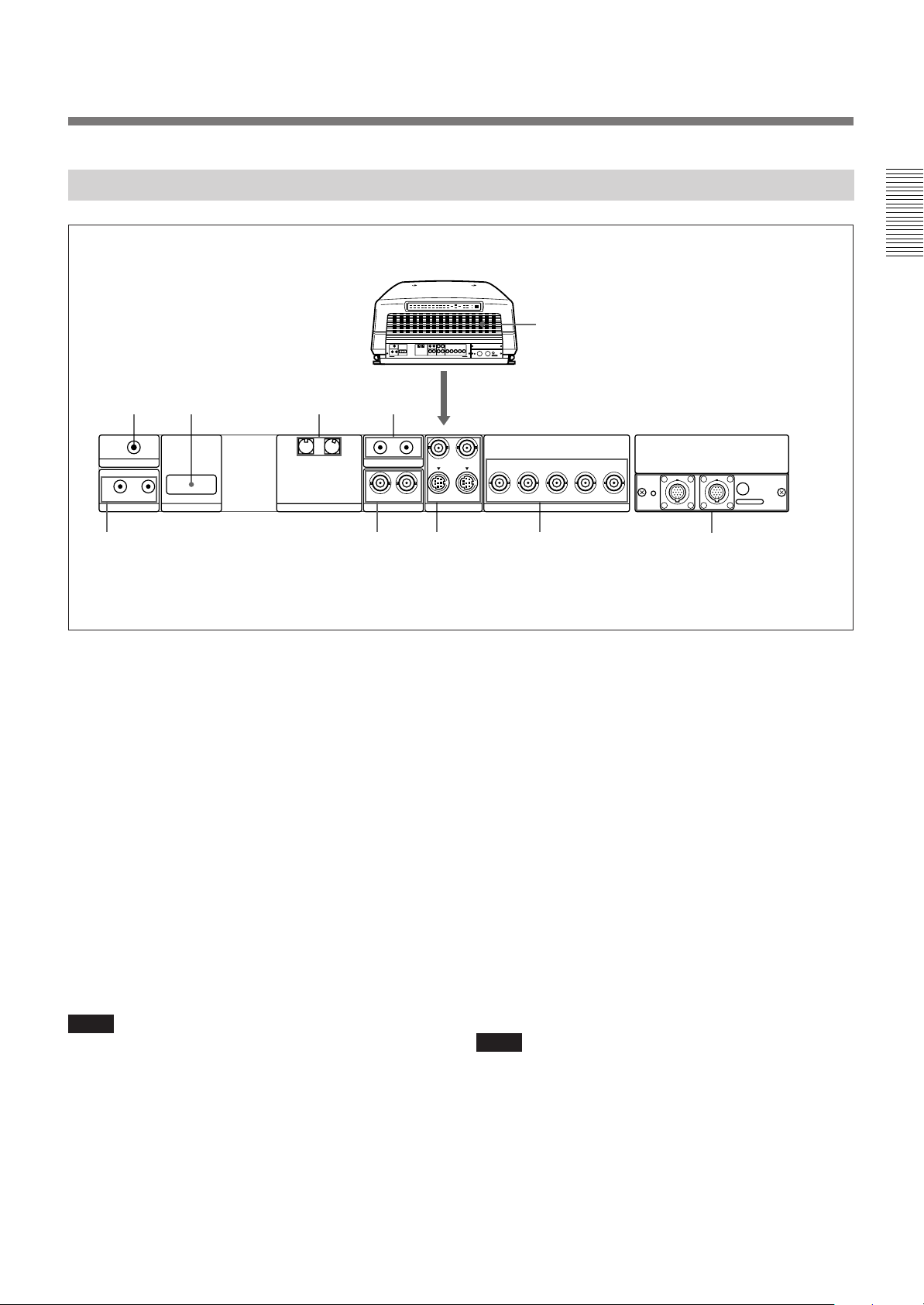
Rear
!º
12 3
TRIGGER
IN OUT
PLUG IN POWER
CONTROL S
RS-422A
REMOTE
INDEX
567
1 TRIGGER connector (minijack)
When the projector is turned on, 5 V is output and
when it is turned off, 0 V is output. However, the
connector is not used as the power source since the
power is not output.
4
IN OUT
ABL LINK
IN IN
VIDEO
Y IN
C IN
S VIDEO
R
OUTOUT
R-Y/P
R
YGB-Y/P
INPUT A
B SYNC/HD VD
B
8
4 ABL (Automatic Brightness Limiter) LINK IN/
OUT jacks (minijack)
When connecting multiple projectors, connects the
ABL LINK OUT jack to the ABL LINK IN jack on
another projector. You can synchronize the brightness
limiting point among the projectors, allowing to make
2 RS-422A REMOTE connector (D-sub 9-pin)
the whole screen brightness uniform.
Used to expand the system connections using the RS422A interface.
Before using the connector, remove the red cap.
5 CONTROL S jacks
IN/PLUG IN POWER (5 V) jack (stereo minijack):
Connects to the CONTROL S OUT jack of other
3 INDEX NO. switches
When multiple projectors are connected, set the index
number of each projector.
To display the index number on the screen, press the
NORMAL key, and the ENTER key on the remote
control.
Note
If you set the index number to “00,” the projector does not
operate.
Sony equipment. Also connects to the CONTROL S
OUT jack of the supplied remote control with the
supplied remote control cable (stereo cable) to be
used as a wired remote control. In this case, this jack
supplys 5 V to the remote control as power source.
OUT jack (stereo minijack): Connects to the
CONTROL S IN jack of other Sony equipment.
Note
When using this jack, the remote control detector on the
projector does not function.
REMOTE1
IN OUT
9
MODE
11 (EN)
Page 12
Location and Function of Controls
6 VIDEO IN/OUT connectors
VIDEO IN connector (BNC type): Connects to the
composite video output of the video equipment.
VIDEO OUT connector (BNC type): Connects to the
composite video input of a color monitor.
7 S VIDEO IN/OUT connectors
Y IN, C IN connectors (BNC type): Connects to the
Y and C video outputs of the video equipment.
S VIDEO IN/OUT connectors (4-pin, mini-DIN
type): Connects to the S video output or input of
the video equipment.
Note
The S VIDEO IN connector is disconnected when a cable is
connected to the Y/C IN connectors.
8 INPUT A connectors (BNC type)
R/R-Y/P
connectors: Connect to the outputs of a computer or a
video camera. According to the connected
equipment, the RGB (R, G, B), component (R-Y, G,
B-Y) or HDTV (P
R, G/Y, B/B-Y/PB, SYNC/HD, VD
R, Y, PB) signal is selected.
9 Signal interface board attachment part (INPUT
B)
The IFB-40 Signal Interface Board is installed by
default. Other optional signal interface boards can be
attached to this section instead of the IFB-40.
Indicator (red): Lights up when the input of the IFB-
40 is selected.
REMOTE 1 IN connector (14-pin multi): When
connecting two projectors, connect to the REMOTE
1 OUT connector on the IFB-40 installed to another
projector.
REMOTE 1 OUT connector (14-pin multi): Connect
to the REMOTE 1 IN connector on the IFB-40.
MODE selector: Turn the control switch of the
MODE selector to the appropriate position according
to the length of the cable connected to the REMOTE
1 OUT connector.
Cable length
Type of cable
Position
up to 2 m
SIC-M-1
CCQ-2BRS
1
up to 10 m
SIC-M-5
CCQ-5BRS
CCQ-10BRS
2
up to 25 m
SIC-M-15
CCQ-25BRS
SIC-M-25
3
up to 50 m
SIC-M-50
CCQ-50BRS
4
!º Rear ventilation hole
12 (EN)
Page 13
Remote Control
The remote control may be used as a wired or wireless
remote control.
The keys with the same names as those on the control
panel have the same functions.
1234 67895
@£
@™
@¡
@º
!ª
!•
!¶
!§
LIGHT
MUTING
PIC
AUDIO OFF
LCD LENS CONTROL
ZOOM
NORMAL
PATTERN
VIDEO SELECT
A D
1
5
9
SHIFT
INPUT SELECT
VIDEO/S VIDEO
B
C
SWITCHER/INDEX
67
0(ALL)
SECOND
STATUS
ON
FOCUS
423
8
SWITCHER
INDEX
!∞
Note
The VOLUME +/– !¢, INPUT SELECT C and D !¶,
AUDIO MUTING @¡ and LCD LENS CONTROL @™ keys
do not function with this projector.
CONTR
OFF
POWER
ON
MENU
ENTER
POSITION
!º
!¡
COMMAND
OFF
RGB
SIZE
SHIFT
BLKG
ON
CENT
R
MEMORY
B
RESET
PICTURE CONTROL
BRIGHT
!™
SHARP VOLUME
HUE COLOR
!£
!¢
1 LIGHT button
Illuminates the key indicators when the COMMAND
switch 6 is set to ON. If the COMMAND switch is
set to OFF, only the COMMAND switch is
illuminated. The key indicators turn off if you press
the LIGHT button again.
If you do not press any key for more than 30 seconds,
the indicators also turn off automatically.
When the remote control is connected to the
CONTROL S IN/PLUG IN POWER jack of the
projector via the remote control cable, the power is
supplied to the remote control from the projector.
2 Transmission indicator
Lights each time you press a key. If it does not light,
replace the batteries with new ones.
3 STATUS ON/OFF key
Press OFF to eliminate the on-screen display.
Press ON to restore the on-screen display.
Note
The menus and warning messages appear even if the OFF
key is pressed.
13 (EN)
Page 14

Location and Function of Controls
4 RGB SHIFT key
Enters the shift adjustment mode for the input signal.
Next adjust the position of the picture using the four
arrow keys. The picture shifts in the direction of the
arrow on the pressed key.
Press the MEMORY key 8 to store the adjusted value
and display the adjusted picture.
5 RGB SIZE key
Enters the size adjustment mode for the input signal.
Next adjust the size of the picture using the four arrow
keys.
B : to reduce horizontal size
b : to expand horizontal size
V : to expand vertical size
v : to reduce vertical size
Press the MEMORY key 8 to store the adjusted value
and display the adjusted picture.
6 COMMAND ON/OFF switch
No key on the remote control except the LIGHT button
1 function when this switch is set to OFF. This saves
battery power.
7 CENT R/B keys
Enter the centering adjustment mode of the red and
blue.
R: Press to enter the red centering adjustment mode.
B: Press to enter the blue centering adjustment mode.
Perform the centering adjustment using the four arrow
keys.
8 MEMORY key
Stores various adjusted data into memory.
9 POWER ON/OFF key
Turns on and off the projector when the MAIN
POWER switch on the projector is set to ON.
0 Menu operation keys
Used for various adjustment functions and for menu
operations.
MENU: Displays the main menu. Press it again to
turn off the menu.
Arrow keys: Adjusts the value or selects the item in
the menu.
ENTER: Stores the settings in the menu.
!™ POSITION +/– keys
Select the position to be adjusted on the screen in
blanking adjustment mode.
Also, set V SHIFT to WIDE or NARROW in the
RGB input signal’s SHIFT adjustment mode.
!£ PICTURE CONTROL keys
Adjust the picture conditions: CONTR (contrast),
BRIGHT (brightness), COLOR, HUE and SHARP
(sharpness).
!¢ VOLUME +/– keys
These keys do not function with this projector.
!∞ SWITCHER/INDEX select switch
Selects the function of the SWITCHER/INDEX keys.
Set to SWITCHER to select the input from the PC-
1271/1271M Signal Interface Switcher.
Set to INDEX to assign the index number of each
projector when multiple projectors are used.
!§ SWITCHER/INDEX keys
When the SWITCHER/INDEX select switch is set
to SWITCHER
When the PC-1271/1271M switcher (not supplied) is
connected to the projector, press a number key (1 – 8)
to select the input from the switcher. The number key
9 does not function.
To select the input from the second switcher (when
the SINGLE/SECOND/OTHER switch on the
switcher is set to SECOND), press a number key
between 1 and 8 within two seconds after pressing the
SECOND key.
When the SWITCHER/INDEX select switch is set
to INDEX
When multiple projectors are connected, select the
index number, which is set with the INDEX NO.
switch on the rear panel, of the projector to be
adjusted. Press a number key (1 – 9) to designate the
index number, then press the ENTER key. When
adjusting all the projectors simultaneously, press the 0
(ALL) key, then the ENTER key.
!¡ RESET key
Resets the adjusted levels to the factory preset or
service preset levels.
14 (EN)
Page 15

!¶ INPUT SELECT keys
Select the input signal.
VIDEO: The video or S video signal input from the
VIDEO IN or S VIDEO IN (or Y/C IN) connectors
SELECT VIDEO/S VIDEO: Selects the signal input
from the VIDEO IN or S VIDEO IN (or Y/C IN)
connectors by pressing this key after pressing the
VIDEO key.
A: The RGB, component or HDTV signal input from
the INPUT A connectors
B: The signal input from the INPUT B section when
the optional interface board other than the IFB-40 is
installed
C, D: These keys do not function with this projector.
Note
To switch the input signal from the INPUT A or INPUT B
to the S VIDEO IN (or Y/C IN) connectors, first press the
VIDEO key, then press the SELECT VIDEO/S VIDEO key.
!• BLKG (blanking) key
Enters the blanking adjustment mode.
You can adjust the blanking with the four arrow keys.
!ª PATTERN key
Displays the internal test patterns of the projector.
Each press of the key displays CROSS HAIR, HATCH
(9 × 9), ME and COLOR BAR patterns, sequentially.
@º NORMAL key
Erases the test pattern or cancels the various
adjustment modes.
@¡ MUTING keys
PIC (picture): Cuts off the picture. To restore the
picture, press the key again.
AUDIO: This key does not funcion with this projector.
@™ LCD LENS CONTROL keys
These keys do not function with this projector.
@£ CONTROL S OUT jack
Connects to the CONTROL S IN/PLUG IN POWER
jack on the projector for wired remote control
application.
15 (EN)
Page 16
Location and Function of Controls
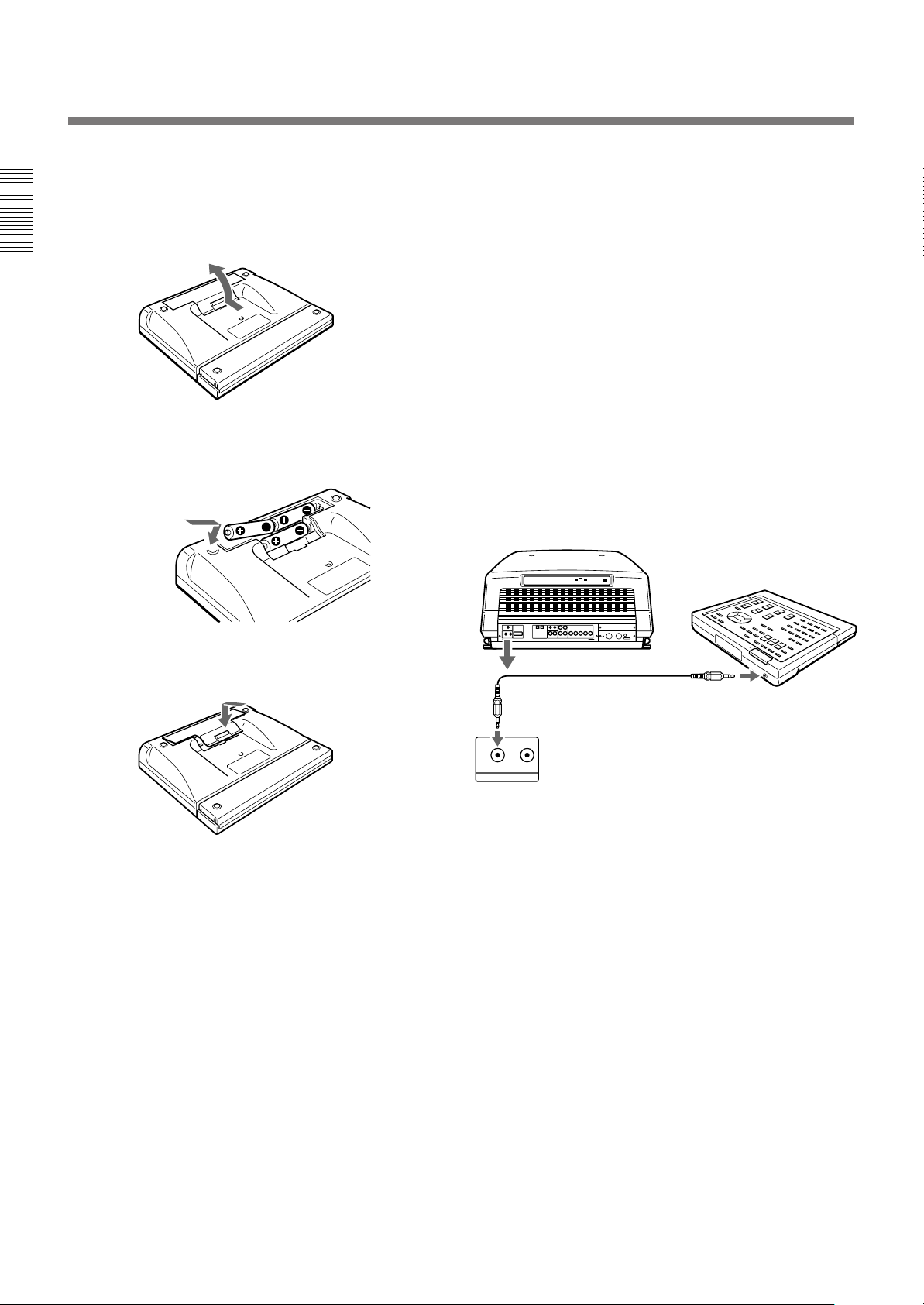
Battery installation
1 Push to open the lid.
2 Install the three size AA (R6) batteries (supplied)
with the correct polarity.
Be sure to install
the battery from
the ’ side.
Notes on wireless remote control operation
•Be sure that there is nothing to obstruct the infrared
beam between the remote control and the projector.
•The operation range is limited. The shorter the
distance between the remote control and the
projector, the wider the angle within which the
remote control can control the projector.
•The remote control detectors on the projector do not
operate when the remote control is being used as a
wired remote control. If you wish to use the remote
control as a wireless remote control, be sure to
remove the connecting cable from both the remote
control and the projector.
Connecting the remote control to the
projector
Rear of the projector
3 Replace the lid.
Notes on batteries
•Be careful that the battery orientation is correct when
inserting batteries.
•Do not mix old battery with new one, or different
types of batteries.
•If you do not intend to use the remote control for a
long time, remove the batteries to avoid damage from
battery leakage. If a battery has leaked, remove the
batteries, wipe the battery compartment dry and
replace the batteries with new ones.
Remote control cable (supplied)
CONTROL S IN
IN OUT
PLUG IN POWER
CONTROL S
CONTROL
S OUT
16 (EN)
Page 17
Projecting
4
5
Front remote control
detector
Control panel
INPUT SELECT
LIGHT
VIDEO
NORMAL
SELECT
VIDEO/S VIDEO
BA
PICTURE CONTROL
BRIGHT-CONTR
-
Projecting
MENU key
2
RGB
MUTING
CENT
PIO
SIZE R
MEMORY
RESET
SHIFT
B
BLKG
STATUS
ON
++
OFF
--
POWER
ON
MENU
STANDBY
ENTER
OFF
IR
POWER ON indicator
Rear remote control detector
u STANDBY indicator
6
1, 6
MAIN POWER
ON/ OFF
4
SWITCHER/INDEX select switch
and number keys
LIGHT
MUTING
PIC
AUDIO OFF
LCD LENS CONTROL
ZOOM
NORMAL
PATTERN
INPUT SELECT
VIDEO SELECT
VIDEO/S VIDEO
B
A D
SWITCHER/INDEX
1
5
67
9
0(ALL)
SECOND
STATUS
ON
FOCUS
SHIFT
C
423
8
SWITCHER
INDEX
COMMAND
ON
OFF
RGB
CENT
SIZE
R
MEMORY
SHIFT
B
RESET
BLKG
PICTURE CONTROL
CONTR
BRIGHT
SHARP VOLUME
HUE COLOR
POWER
ON
OFF
MENU
ENTER
POSITION
6
2
MENU key
5
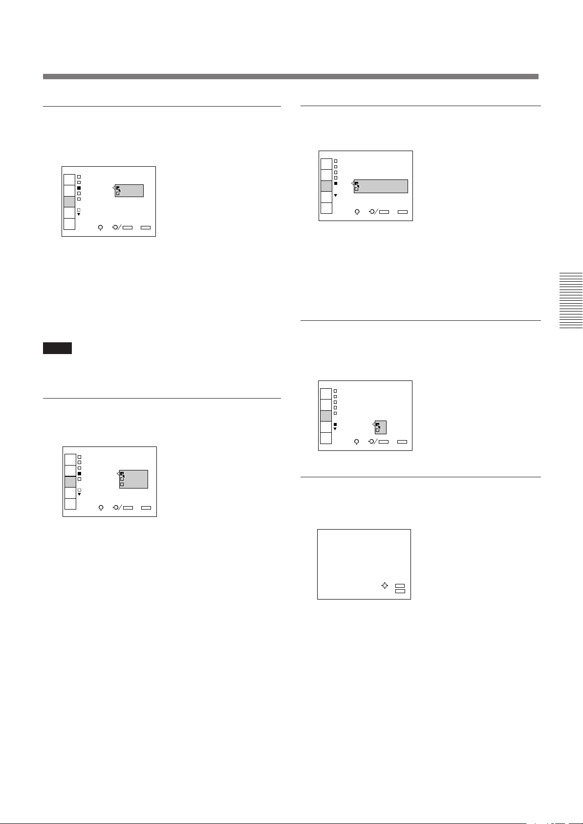
1 Press the MAIN POWER switch on the front of the projector.
The u STANDBY indicator on the control panel lights in orange and
the projector goes into the standby mode.
2 Press the POWER ON key on the remote control or the control panel.
The POWER ON indicator lights in green.
A white screen with the message shown below (warming up screen)
appears on the screen. Make sure to allow the projector to warm up for
20 minutes after turning it on.
The message disappears temporarily in about 35 seconds, and will
appear subsequently for 5 seconds every 30 seconds.
INPUT-A
For optimum
performance
white screen will
remain for 20min.
For immediate use,
push [MENU] key.
Press the MENU key to cancel the warming up screen and see the
picture immediately after the projector is turned on if, for example, the
adjustment has been finished and warming up is not needed.
(continued)
17 (EN)
Page 18
Projecting
3 Turn on the power of the connected equipment.
4 Select the input signal to be projected by pressing the INPUT SELECT
key.
VIDEO and SELECT keys: To project the signal input from the
equipment connected to the VIDEO IN or S VIDEO IN (or Y/C IN)
connectors. Select VIDEO or S VIDEO by pressing the VIDEO key,
then the SELECT key.
A: To project the RGB, component or the HDTV signal input from the
equipment connected to the INPUT A connectors.
B: To project the signal input from the equipment connected to the
optional interface board other than the IFB-40 installed to the
INPUT B section.
When the PC-1271/1271M Signal Interface Switcher is connected:
Set the SWITCHER/INDEX select switch on the remote control to
SWITCHER and then select the input with the number keys 1 to 8.
If two switchers are connected, press the SECOND key and then the
number key to select the input from the second switcher.
Note
When you select the input signal connected to the INPUT A or INPUT B section,
be sure to select the correct signal in the SET SETTING menu. If an incorrect
signal is selected, picture may be distorted.
For details, see “The SET SETTING Menu” on page 31 (EN).
5 Adjust the picture.
For details, see “Adjusting the Picture” on page 19 (EN).
6 To turn the power off, press the POWER OFF key on the remote
control or on the control panel of the projector, then set the MAIN
POWER switch on the projector to OFF.
To Press
Trun off the on-screen display
Cut off the picture the MUTING PIC key.
the STATUS OFF key. The menus and
warning messages appear even if the
OFF key is pressed.
To restore the on-screen display, press
the STATUS ON key.
To restore the picture, press the
MUTING PIC key.
18 (EN)
Page 19
Adjusting the Picture
Adjust the picture for your preference. The adjustment data can be saved in
the memory.
1 Adjust with the PICTURE CONTROL +/– keys.
Only the remote control is equipped with the COLOR, HUE and
SHARP keys.
BRIGHT Brightness
CONTR Picture contrast
COLOR Color intensity
HUE Hue
SHARP Sharpness
The adjustment levels are digitally displayed with a range of MIN, 1, 2, ...
99, MAX.
BRIGHT: 50
Restoring the initial data
2 Press the MEMORY key to save the data.
Dynamic picture mode (only for the video or component input
pictures)
You can get high quality picture contrast by setting D.PICTURE to ON in
the PIC CTRL menu.
For details, see “PIC CTRL (Picture Control) menu” on page 26 (EN).
1 Press the PICTURE CONTROL key of the item which you want to
reset to the initial data.
2 Press the RESET key.
The selected item is reset to the initial data.
Notes
• The COLOR, SHARP and HUE keys do not function on the pictures input from
the RGB IN connectors.
• The HUE and COLOR keys do not function if the input signal is black and
white.
• The HUE key does not function with the PAL or SECAM color input source.
19 (EN)
Page 20
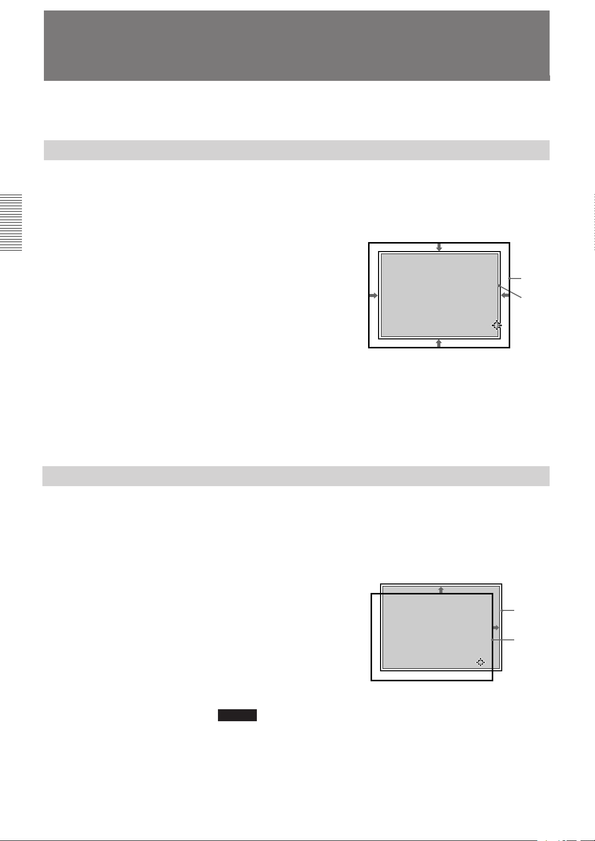
Adjusting the Size And Shift of the Picture
The size and shift of the input picture can be adjusted to fit the screen.
SIZE adjustment
Adjust the picture size if it does not fit the screen.
1 Press the RGB SIZE key.
(Use the RGB SIZE key even for the signal other than RGB.)
SHIFT adjustment
2 Adjust the picture size with
the arrow keys.
V : The vertical size is
expanded.
v : The vertical size is
reduced.
b : The horizontal size is
expanded.
B : The horizontal size is
reduced.
RGB SIZE ADJ
Hc: 80
Hf: 80
Vc: 80
Vf: 80
Picture
Screen
ADJ:
3 Press the MEMORY key to save the adjustment data.
Resetting to the initial preset size
The picture size of the video signal can be reset to the initial preset size by
pressing the RESET key in RBG SIZE adjustment mode. (The picture size
of signals other than the video signal cannot be reset.)
If the picture needs to be shifted to fit the screen, adjust the position of the
picture.
20 (EN)
1 Press the RGB SHIFT key.
(Use the RGB SHIFT key even for the signal other than RGB.)
2 Adjust the shift with the
arrow keys.
V : The picture is shifted
upward.
v : The picture is shifted
downward.
b : The picture is shifted
rightward.
B : The picture is shifted
leftward.
Notes
When the RGB signal is input, the adjustable range of the vertical shift (V SHIFT)
can be set to WIDE or NARROW by pressing the POSITION +/– keys.
When the video signal is input, V SHIFT is automatically fixed to NARROW and
the adjustable range of the vertical shift will become narrower than that of the
RGB signal.
RGB SHIFT ADJ
V SHIFT:
NARROW
Hc: 50
Hf: 50
V :MIN
ADJ:
Screen
Picture
Page 21
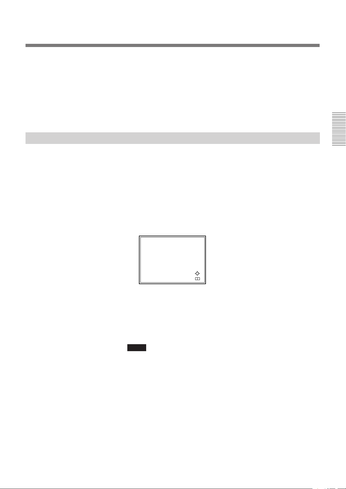
Blanking adjustment
3 Press the MEMORY key to save the adjustment data.
Resetting to the initial preset position
The position of the picture of the video signal can be reset to the initial
preset position by pressing the RESET key in RGB SHIFT adjustment
mode. (The position of the picture of signals other than the video signal
cannot be reset.)
If the displayed picture is larger than the screen, cut off the excess parts.
1 Press the BLKG key.
2 Press the POSITION +/– keys on the remote control to select the part
to be adjusted.
• When you press the + key, the position cycles through the following
order:
TOP → BOTTOM → LEFT → RIGHT → TOP…
• When you press the – key, the position cycles in reverse order.
BLKG ADJ
TOP
T: 50
B: 50
L:MAX
R: 50
ADJ:
NEXT:
+ –
3 Adjust with the arrow keys.
• Press the V and v keys to adjust the TOP and BOTTOM positions.
• Press the B and b keys to adjust the LEFT and RIGHT positions.
4 Press the MEMORY key to save the adjustment data.
Note
When you connect multiple video input sources to the projector, such as when
using the switcher, adjust the picture size, picture shift and blanking for each input
connector.
21 (EN)
Page 22
Centering Adjustment
The three colors, red, green and blue must converge for correct projection.
If they do not converge, centering adjustment is necessary.
MEMORY key
CENT R/B key
LIGHT
NORMAL
VIDEO
SELECT
INPUT SELECT
VIDEO/S VIDEO
BA
PICTURE CONTROL
BRIGHT-CONTR
-
Control panel
POWER ON key
STATUS
MUTING
RGB
ON
++
OFF
--
CENT
PIO
SIZE R
MEMORY
BLKG
SHIFT
B
RESET
POWER
ON
MENU
STANDBY
ENTER
OFF
IR
Rear remote control detector
Arrow keys (V, v, B, b)
Front remote control detector
MAIN POWER switch
CENT R key
CENT B key
LIGHT
MUTING
PIC
AUDIO OFF
LCD LENS CONTROL
ZOOM
NORMAL
PATTERN
INPUT SELECT
VIDEO SELECT
VIDEO/S VIDEO
B
A D
SWITCHER/INDEX
1
5
67
9
0(ALL)
SECOND
STATUS
ON
FOCUS
SHIFT
C
423
8
SWITCHER
INDEX
COMMAND
ON
OFF
RGB
CENT
SIZE
R
MEMORY
SHIFT
B
RESET
BLKG
PICTURE CONTROL
CONTR
BRIGHT
SHARP VOLUME
HUE COLOR
POWER
ON
OFF
MENU
ENTER
POSITION
POWER ON key
MEMORY key
Arrow keys (V, v, B, b)
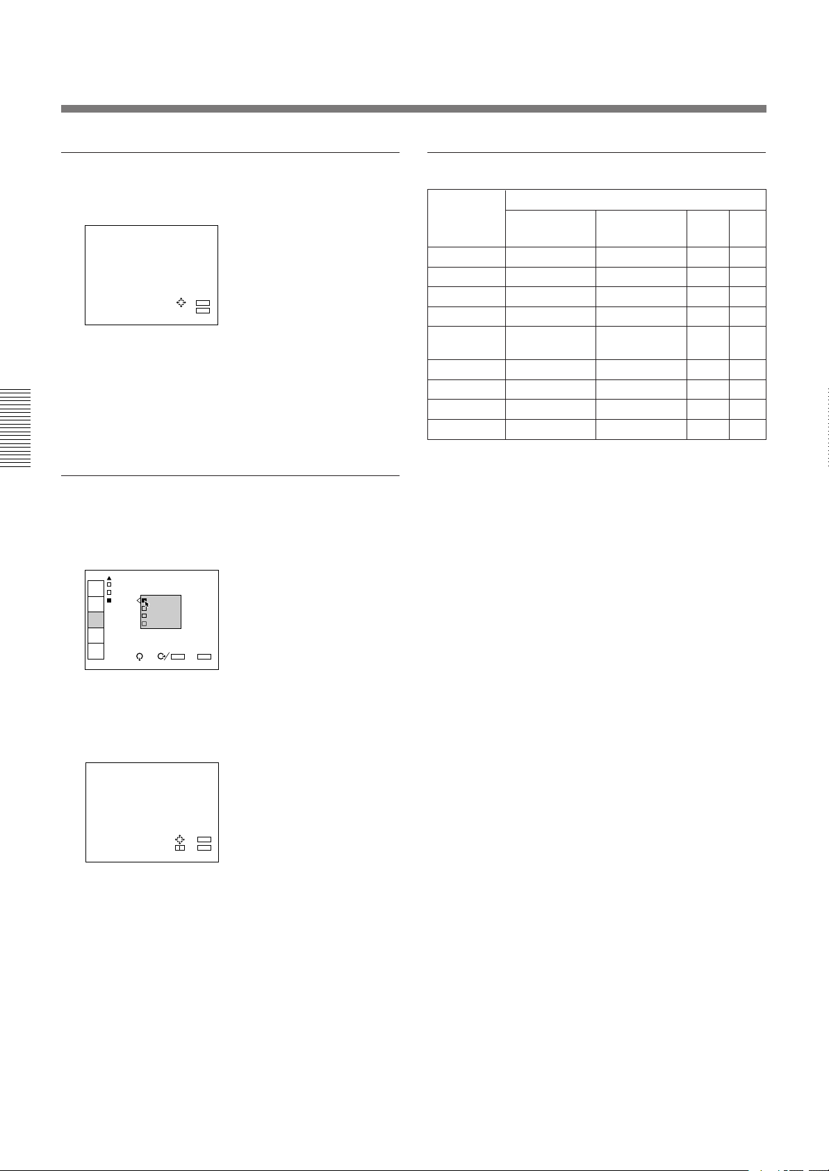
1 Turn the projector on by switching on the MAIN POWER switch and
pressing the POWER ON key on the remote control.
2 Press the CENT R key.
The built-in CROSS HAIR test pattern appears and the red line will be
adjustable.
Blue Green Red
22 (EN)
R CENT ADJ
R CENT ADJ
R CENT ADJ
Hc:128
Hc:128
Hf:128
Hc:128
Hf:128
Vc:118
Hf:128
Vc:118
Vf:130
Vc:118
Vf:130
Vf:130
ADJ:
ADJ:
ADJ:
Red
Green
Blue
Page 23
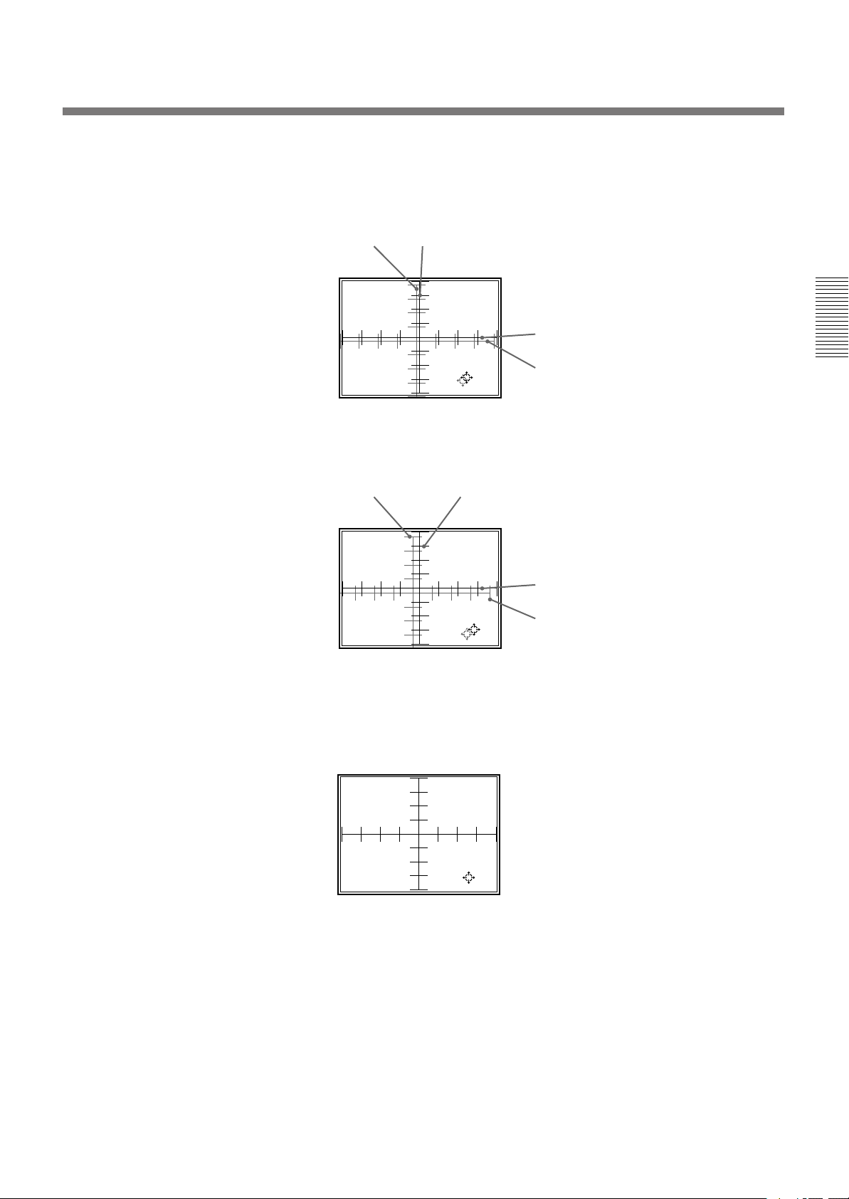
3 Press the arrow keys to move the red line until the red and green lines
converge and become yellow.
The red line moves according to the direction of the arrow.
Blue Yellow
R CENT ADJ
R CENT ADJ
Yellow
Hc:128
Hc:128
Hf:128
Hf:128
Vc:118
Vc:118
Vf:130
Vf:130
ADJ:
ADJ:
Blue
4 Press the CENT B key.
The blue line will be adjustable.
Blue
B CENT ADJ
B CENT ADJ
Hc:128
Hc:128
Hf:128
Hf:128
Vc:118
Vc:118
Vf:130
Vf:130
Yellow
ADJ:
ADJ:
Yellow
Blue
5 Press the arrow keys to move the blue line until the blue and yellow
lines converge.
The blue line moves according to the direction of the arrow.
When all three color lines converge, the test pattern will become white.
B CENT ADJ
Hc:128
Hf:128
Vc:118
Vf:130
ADJ:
6 Press the MEMORY key.
The normal display is restored.
23 (EN)
Page 24
INPUT-A
VIDEO:VIDEO
INPUT-A
INPUT-B
SWITCHER:SW'ER1-1
INPUT
SELECT
PIC
CTRL
INPUT
SETTING
SET
SETTING
INPUT
INFO.
SEL: SET:
ENTER
EXIT: MENU
Using the Menu
The projector is equipped with an on-screen menu for
making various adjustments and settings.
The language used in the menu can be changed to
French, German, Italian, Spanish, Japanese or Chinese.
For details, see “LANGUAGE” on page 32 (EN).
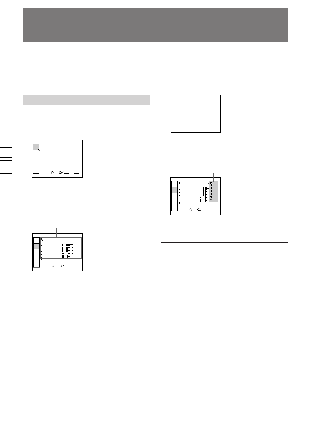
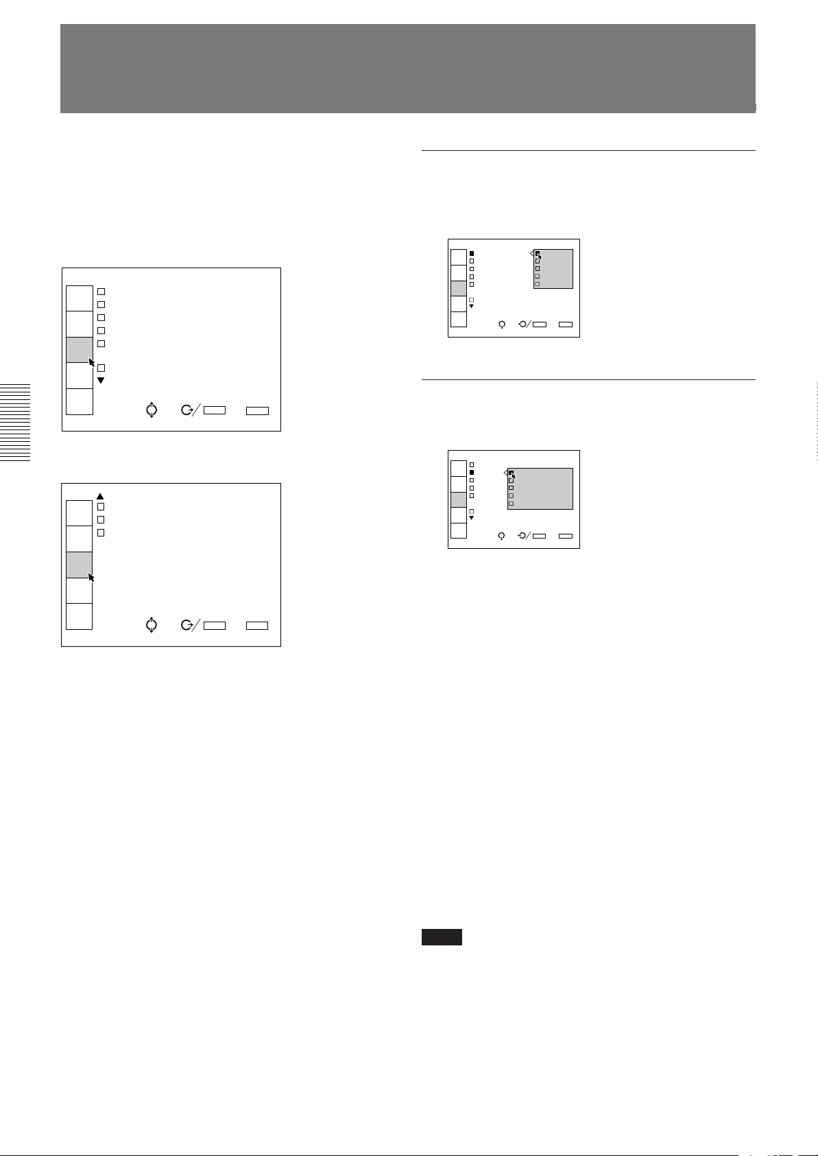
Basic Menu Operation
1 Press the MENU key.
The menu display appears.
The menu presently selected is highlighted in blue.
2 Use the v or V keys to select a menu, then press
the b key or the ENTER key.
The selected menu appears.
The setting items that are indicated in white
cannnot be selected.
To change the adjustment level
To increase the level, press the V or b key.
To decrease the level, press the v or B key.
Then press the ENTER key to store the level. The
original screen is restored.
CONTRAST: 80
To select an item
Use the v or V key to select an item in a pop-up menu,
then press the B key or the ENTER key. The selected
setting is stored and the pop-up menu disappears.
Pop-up menu
VIDEO MEMORY: OFF
INPUT
SELECT
1
CONTRAST 2
PIC
CTRL
BRIGHT 3
COLOR 4
INPUT
SETTING
HUE 5
SHARP
SET
SETTING
INPUT
INFO.
SEL: SET:
EXIT: MENU
ENTER
Menu items
VIDEO
VIDEO MEMORY:OFF
INPUT
SELECT
CONTRAST 80
PIC
CTRL
BRIGHT 50
COLOR 50
INPUT
SETTING
HUE 50
SHARP 50
SET
SETTING
INPUT
INFO.
Setting items
SEL: SET:
ENTER
RESET: RESET
EXIT: MENU
3 Use the v or V keys to select a setting item, then
press the b key or the ENTER key.
The adjustment menu or the setting menu (pop-up
menu) appears.
If there are two or more pages for a menu
The $ indication appears below the bottom item.
To go to the next page, move the cursor to the
bottom item with the v key, then press the v key.
To go back to the previous page, move the cursor
to the top item with the V key, then press the V key.
4 Make adjustment or setting on the menu.
For details on setting individual items, see the relevant
menu pages.
To clear the menu display
Press the MENU key.
The menu display also disappears automatically if no
key is pressed for about one minute.
To reset the settings that have been
adjusted
Press the RESET key. “Reset complete!” appears on
the screen and the settings appearing on the screen will
be reset to the factory preset or service adjusted levels.
Memory of the settings
The settings in the menus are automatically stored in
the projector memory. You can also store the setting
by pressing the MEMORY key.
24 (EN)
Page 25
INPUT-A
VIDEO:VIDEO
INPUT-A
INPUT-B
SWITCHER:SW'ER1-1
INPUT
SELECT
PIC
CTRL
INPUT
SETTING
SET
SETTING
INPUT
INFO.
SEL: SET:
ENTER
EXIT: MENU
INPUT-A
VIDEO:VIDEO
INPUT-A
INPUT-B
SWITCHER:SW'ER1-1
INPUT
SELECT
PIC
CTRL
INPUT
SETTING
SET
SETTING
INPUT
INFO.
SEL: SET:
ENTER
EXIT: MENU
The INPUT SELECT Menu
Adjustments and settings using the menu
The INPUT SELECT menu is used for selecting the
input signal.
Items that can be selected are highlighted in green.
You cannot select the items indicated in white.
INPUT-A
VIDEO:VIDEO
INPUT
SELECT
INPUT-A
INPUT-B
PIC
CTRL
SWITCHER:SW'ER1-1
INPUT
SETTING
SET
SETTING
INPUT
INFO.
SEL: SET:
ENTER
EXIT: MENU
VIDEO
Selects signal input from the VIDEO IN or S VIDEO
IN (or Y/C IN) connectors.
DEO
VIDEO: VIDEO
INPUT
SELECT
INPUT- S-VIDEO
INPUT-
PIC
CTRL
SWITCHER:SW'ER1-1
INPUT
SETTING
SET
SETTING
INPUT
INFO.
SEL: SET:
EXIT: MENU
ENTER
Select VIDEO or S-VIDEO in the pop-up menu.
INPUT-A
Selects signal input from the INPUT A connectors.
INPUT-B
Selects signal input from the connectors on the signal
interface board (not supplied) installed to the INPUT B
section.
Notes
• When the PC-1271/1271M Signal Interface Switcher is
connected to the projector via the IFB-40 Signal Interface
Board installed to the INPUT B section, INPUT-B cannot
be selected.
• If the setting of INPUT-B in the SET SETTING menu is
incorrect, the pictue may be distorted.
For details, see page 31 (EN).
SWITCHER
When the PC-1271/1271M Signal Interface Switcher
is connected to the projector, selects signal input from
the switcher.
INPUT-A
VIDEO:VIDEO
INPUT
SELECT
INPUT-A
INPUT-B
PIC
CTRL
SWITCHE SW ER 1-1
SW ER 1-2
INPUT
SETTING
SW ER 1-3
SW ER 1-4
SET
SETTING
INPUT
INFO.
SEL: SET:
EXIT: MENU
ENTER
Notes
• When the PC-1271/1271M Signal Interface Switcher is
connected to the INPUT A connectors using the 5BNC
cables, INPUT-A cannot be selected.
• If the setting of INPUT-A in the SET SETTING menu is
incorrect, the picture may be distorted.
For details, see page 31 (EN).
You can select SW'ER1-1 to SW'ER2-8 in the pop-up
menu. They are always displayed in green even when
no signal is input.
Note
SWITCHER can be selected only when the IFB-40 Signal
Interface Board is installed to the INPUT B section, or when
5BNC MODE in the SET SETTING menu is set to ON.
25 (EN)
Page 26
The PIC CTRL (Picture Control) Menu
The PIC CTRL menu is used for adjusting the picture.
Items that can be adjusted are highlighted in green.
You cannot select the items indicated in white.
Page 1
VIDEO
VIDEO MEMORY:OFF
INPUT
SELECT
CONTRAST 80
PIC
CTRL
BRIGHT 50
COLOR 50
INPUT
SETTING
HUE 50
SHARP 50
SET
SETTING
INPUT
INFO.
SEL: SET: ENTER
RESET: RESET
EXIT: MENU
Page 2
VIDEO
D.PICTURE:OFF
INPUT
SELECT
COLOR SYS:AUTO
SET UP:0
PIC
CTRL
INPUT
SETTING
SET
SETTING
INPUT
INFO.
SEL: SET:
ENTER
EXIT: MENU
CONTRAST
Adjusts the picture contrast.
CONTRAST: 80
The higher the setting, the greater the contrast.
The lower the setting, the lower the contrast.
BRIGHT
Adjusts the picture brightness.
BRIGHT: 50
The higher the setting, the brighter the picture.
The lower the setting, the darker the picture.
COLOR
Adjusts color intensity.
COLOR: 50
VIDEO MEMORY
Selects a memory number of the adjusted picture
levels.
VIDEO MEMORY: OFF
INPUT
SELECT
1
CONTRAST 2
PIC
CTRL
BRIGHT 3
COLOR 4
INPUT
SETTING
HUE 5
SHARP
SET
SETTING
INPUT
INFO.
SEL: SET:
EXIT: MENU
ENTER
Select a number from 1 to 10 in the pop-up menu, then
the picture levels that have been adjusted will be stored
in the number of the projector's memory.
If you want to use the data at the factory preset levels,
select OFF.
The items to be stored in the VIDEO MEMORY are
shown in the table of the memory architecture under
“Input memory” (except for the items, “clamp
position” and “registration” ).
26 (EN)
The higher the setting, the greater the intensity.
The lower the setting, the lower the intensity.
HUE
Adjusts skin tones.
HUE: 50
At high settings, the picture becomes greenish.
At low settings, the picture becomes purplish.
SHARP
Adjusts the picture sharpness.
SHARP: 50
The higher the setting, the sharper the picture.
The lower the setting, the softer the picture.
Page 27
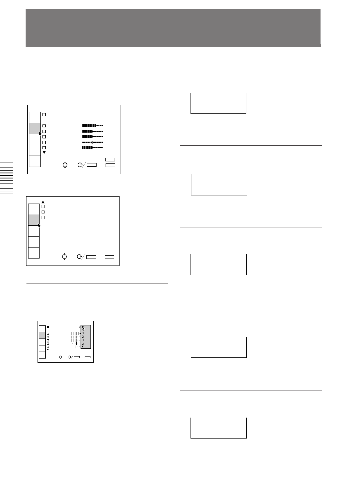
D. (Dynamic) PICTURE
SET UP
Emphasizes the black of the composite video, S video
(Y/C) or component signal.
VIDEO
D.PICTURE: ON
INPUT
SELECT
COLOR SYS: OFF
SET UP:0
PIC
CTRL
INPUT
SETTING
SET
SETTING
INPUT
INFO.
SEL: SET:
EXIT: MENU
ENTER
ON: Emphasizes the black to produce a bolder
“dynamic” picture.
OFF: Reproduces the dark portions of the picture
accurately, in accordance with the source signal.
COLOR SYS (System)
Selects the color system of the composite video or S
video (Y/C) signal.
VIDEO
D.PICTUR AUTO
INPUT
SELECT
COLOR SY NTSC3.58
SET UP:0 PAL
PIC
CTRL
SECAM
NTSC4.43
INPUT
SETTING
PAL-M
SET
SETTING
INPUT
INFO.
SEL: SET:
Normally, set to AUTO.
If the picture is distorted or colorless, select the color
system according to the input signal.
EXIT: MENU
ENTER
Changes the set up level (standard black level) to 0
IRE or 7.5 IRE according to the NTSC source signal.
VIDEO
D.PICTURE:OFF
INPUT
SELECT
COLOR S O
SET UP: 0
PIC
CTRL
7.5
INPUT
SETTING
SET
SETTING
INPUT
INFO.
SEL: SET:
EXIT: MENU
ENTER
0 IRE: Normally, set to this position.
7.5 IRE: Set to this position when the black color is
too light.
Input signals and adjustable/setting items
Input signal
3.58/
3.58/
Component
Y
Y
Y
N
Y
Y
N
N
HDTV
Y
Y
Y
Y
Y
N
N
N
RGB
Y
Y
N
N
N
N
N
N
Items
CONTRAST
BRIGHT
COLOR
HUE
SHARP
D. PICTURE
COLR SYS
SET UP
Video or S
video (Y/C)
Y
Y
Y
Y (NTSC
4.43
NTSC
system only)
Y
Y
Y
Y (NTSC
4.43
NTSC
system only)
Y: Adjustable/can be set
N: Not adjustable/cannot be set
27 (EN)
Page 28
The INPUT SETTING Menu
The INPUT SETTING menu is used to adjust the
input signal.
Items that can be adjusted are displayed in green.
You cannot select the items indicated in white.
Page 1
INPUT-A
COLOR TEMP:6500
INPUT
SELECT
CLAMP:AUTO
V SHIFT:WIDE
PIC
CTRL
SYNC SEL:AUTO
COMPONENT FORMAT:
INPUT
SETTING
SMPTE/EBU-N10
SYNC OSC:1
SET
SETTING
INPUT
INFO.
SEL: SET:
ENTER
EXIT: MENU
Page 2
INPUT-A
RGB SIZE
INPUT
SELECT
RGB SHIFT
BLKG
PIC
CTRL
INPUT
SETTING
SET
SETTING
INPUT
INFO.
SEL: SET:
ENTER
EXIT: MENU
COLOR TEMP (Temperature)
Selects the appropriate color temperature according to
your application and the input source signal.
COLOR TEMP 9300
INPUT
SELECT
CLAMP:AUTO 6500
V SHIFT:WI 5400
PIC/AU
CTRL
SYNC SEL:A 3200
COMPONENT PRESET
INPUT
SETTING
SMPTE
SYNC OSC:1
SET
SETTING
INPUT
INFO.
SEL: SET:
ENTER
EXIT: MENU
CLAMP
Corrects the luminance of the input picture.
INPUT-A
COLOR
INPUT
SELECT
CLAMP AUTO
V SHI SonG
PIC/AU
CTRL
SYNC H/C
COMPO HP
INPUT
SETTING
TRI-LEVEL S
SYNC
SET
SETTING
INPUT
INFO.
SEL: SET:
CLAMP is used as a standard for setting the black
level of a picture correctly. The standard position of
the clamp depends on the kind of sync signal being
used. Normally, the projector CPU judges the signal
and sets the position automatically. However, the CPU
can misjudge the signal because of noise. If the
luminance of the picture seems to be incorrect, the
clamp position may need to be changed.
ENTER
EXIT: MENU
28 (EN)
AUTO: Automatic setting mode. Normally set to this
position.
SonG: Set to this position if the black seems too light
or greenish.
H/C: Set to this position if the picture is too dark or
luminance is unstable.
HP: If the luminance is still incorrect after changing
to the SonG or H/C position, set to this position
and perform the H-SHIFT adjustment.
TRI-LEVEL/S: Set to this position if the picture is
dark when using the tri-level sync.
Note
If the luminance is still incorrect after changing the clamp
setting, check the input signal and the connections.
Page 29
V (vertical) SHIFT
COMPONENT FORMAT
Sets the adjustable range of the vertical shift of the
input signal.
INPUT-A
COLOR TEMP:6500
INPUT
SELECT
CLAMP:AU
V SHIFT: WIDE
PIC/AU
CTRL
SYNC SEL NARROW
COMPONEN
INPUT
SETTING
SMPTE/EBU-N10
SYNC OSC:1
SET
SETTING
INPUT
INFO.
SEL: SET:
ENTER
EXIT: MENU
WIDE: Normally, set to this position (factory preset).
NARROW: When some signal such as a
superimposed signal with unstable vertical sync.
signal is input, the picture may be distorted
vertically. In this case, set to this position.
Adjustable range in the lower direction will
become narrow.
Note
When the video, S video or component signal is input, V
SHIFT is fixed to NARROW.
SYNC SEL (select)
Selects the sync signal.
INPUT-A
COLOR TEMP:6500
INPUT
SELECT
CLAMP:AUTO
V SHIFT:W
PIC/AU
CTRL
SYNC SEL: AUTO
COMPONENT S on G
INPUT
SETTING
SMPT H/C V
SYNC OSC:
SET
SETTING
INPUT
INFO.
SEL: SET:
ENTER
EXIT: MENU
Selects the format of the component input signal.
INPUT-A
COLOR TEMP:6500
INPUT
SELECT
CLAMP:AUTO
V SHIFT:WIDE
PIC/AU
CTRL
SYN
COM SMPTE/EBU-N10
INPUT
SETTING
BETACAM7.5
SET
SETTING
INPUT
INFO.
SEL: SET:
ENTER
EXIT: MENU
SMPTE/EBU-N10: Set to this position if the input
signal is the SMPTE or EBU-N10 format
component signal.
BETACAM7.5: Set to this position if the input signal
is the Betacam format component signal.
SYNC OSC (oscillation)
Normally, set to 1. When synchronization is distorted
according to the type of the input signal, set to 2.
INPUT-A
COLOR TEMP:6500
INPUT
SELECT
CLAMP:AUTO
V SHIFT:WIDE
PIC/AU
CTRL
SYNC SEL:AUTO
COMPONENT FORMAT:
INPUT
SETTING
SMPT U-N10
SYNC OSC: 1
SET
SETTING
2
INPUT
INFO.
SEL: SET:
ENTER
EXIT: MENU
RGB SIZE
Adjusts the picture size of the input signal.
AUTO: Automatic setting mode. Normally set to this
position.
S on G: Set to this position if you project the picture
using the sync on G signal.
H/C V: Set to this position if you project the picture
using the external sync signal.
When an HDTV signal is input
You can select the items below instead of the above
items.
INT: Set to this position when using the internal sync
signal.
EXT (C): Set to this position when using the external
composite sync signal.
EXT (HV): Set to this position when using the
external horizontal/vertical sync signal.
RGB SIZE ADJ
Hc:128
Hf:128
Vc:128
Vf:128
ADJ:
SET:
ENTER
EXIT: MENU
Use the B or b key to adjust the horizontal size.
Use the V or v key to adjust the vertical size.
Hc and Hf show the size adjustment levels for the
horizontal direction and Vc and Vf show those for the
vertical direction. The higher the setting level, the
greater the picture size.
29 (EN)
Page 30
The INPUT SETTING Menu
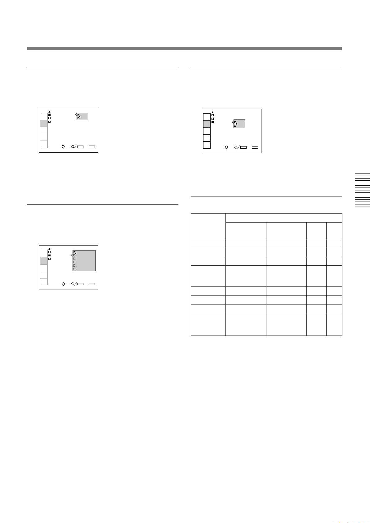
RGB SHIFT
Adjusts the picture position of the input signal.
RGB SHIFT ADJ
V SHIFT:
WIDE
Hc:128
Hf:128
V :128
ADJ:
SET:
ENTER
EXIT: MENU
Use the B or b key to adjust the horizontal position.
Use the V or v key to adjust the vertical position.
Hc and Hf show the shift adjustment levels for the
horizontal direction and V shows the level for the
vertical direction.
BLKG (Blanking)
Cuts off the excess parts if the displayed picture is
larger than the screen.
Input signals and adjustable/setting items
Input signal
Items
Video or
S video (Y/C)
COLOR TEMP
CLAMP
V SHIFT
SYNC SEL
COMPONENT
Y
N
N
N
N
FORMAT
SYNC OSC
RGB SIZE
RGB SHIFT
BLKG
Y
Y
Y
Y
Y: Adjustable/can be set
N: Not adjustable/cannot be set
Component
Y
N
N
N
Y
Y
Y
Y
Y
HDTV
Y
Y
Y
Y
N
Y
Y
Y
Y
RGB
Y
Y
Y
Y
N
Y
Y
Y
Y
INPUT-A
RGB SIZE
INPUT
SELECT
RGB
BLKG TOP
PIC
CTRL
BOTTOM
LEFT
INPUT
SETTING
RIGHT
SET
SETTING
INPUT
INFO.
SEL: SET:
ENTER
EXIT: MENU
Select the part to be adjusted among TOP, BOTTOM,
LEFT and RIGHT, then press the b key or the ENTER
key to display the blanking adjustment screen.
BLKG ADJ
TOP
T:MAX
B:MIN
L:MIN
R:MAX
ADJ:
SET:
ENTER
NEXT:
+ –
EXIT:
MENU
Use the V or v key to adjust the TOP and BOTTOM
parts.
Use the B or b key to adjust the LEFT and RIGHT
parts.
30 (EN)
Page 31

INPUT-A
STATUS:ON
PIC.MUTING: ON
INPUT-A:RGB OFF
INPUT-B:RGB
LANGUAGE:ENGLISH
ABG MODE:ON
INPUT
SELECT
PIC
CTRL
INPUT
SETTING
SET
SETTING
INPUT
INFO.
SEL: SET:
ENTER
EXIT: MENU
INPUT-A
STATUS:ON
PIC.MUT
INPUT-A RGB
INPUT-B COMPONENT
LANGUAG HDTV-YPBPR
ABG MOD HDTV-GBR
INPUT
SELECT
PIC
CTRL
INPUT
SETTING
SET
SETTING
INPUT
INFO.
SEL: SET:
ENTER
EXIT: MENU
INPUT-A
STATUS:
PIC.MUT RGB
INPUT-A COMPONENT
INPUT-B HDTV-YPBPR
LANGUAG HDTV-GBR
ABG MOD VIDEO
S-VIDEO
INPUT
SELECT
PIC
CTRL
INPUT
SETTING
SET
SETTING
INPUT
INFO.
SEL: SET:
ENTER
EXIT: MENU
The SET SETTING Menu
The SET SETTING menu is used for changing the
default settings of the projector.
Items that can be adjusted are highlighted in green.
You cannot select the items indicated in white.
Page 1
INPUT-A
STATUS:ON
INPUT
SELECT
PIC.MUTING:OFF
INPUT-A:RGB
PIC
CTRL
INPUT-B:RGB
LANGUAGE:ENGLISH
INPUT
SETTING
ABG MODE:OFF
SET
SETTING
INPUT
INFO.
SEL: SET:
ENTER
EXIT: MENU
Page 2
INPUT-A
SCREEN SEL:1
INPUT
SELECT
SIRCS RECEIVER:
FRONT&REAR
PIC
CTRL
POWER SAVING:OFF
PATTERN:OFF
INPUT
SETTING
INDEX:01
5BNC MODE:OFF
SET
SETTING
INPUT
INFO.
SEL: SET:
ENTER
EXIT: MENU
PIC. (picture) MUTING
Set to ON to cut off the picture.
When set to ON, “PIC MUTING” appears on the
screen.
INPUT-A
Selects the signal input from the INPUT A connectors.
RGB: Inputs the RGB signal.
COMPONENT: Inputs the component signal.
HDTV-YPBPR: Inputs the HDTV (YP
HDTV-GBR: Inputs the HDTV(GBR) signal.
BPR) signal.
STATUS
Selects the on-screen display mode.
A
STATUS: ON
INPUT
SELECT
PIC.MUT OFF
INPUT-A ALL OFF
PIC
CTRL
INPUT-B
LANGUAGE:ENGLISH
INPUT
SETTING
ABG MODE:ON
SET
SETTING
INPUT
INFO.
SEL: SET:
ON: Shows all of the on-screen displays.
OFF: Turns off the on-screen displays except for
“NO INPUT,” “PIC MUTING,” warning
messages and menu displays.
ALL OFF: Turns off all of the on-screen displays
except for warning messages and menu displays.
INPUT B
Selects the signal input from the IFB-12 Signal
Interface Board (not supplied) installed to the INPUT
B section.
ENTER
EXIT: MENU
RGB: Inputs the RGB signal.
COMPONENT: Inputs the component signal.
HDTV-YPBPR: Inputs the HDTV (YP
BPR) signal.
HDTV-GBR: Inputs the HDTV(GBR) signal.
VIDEO: Inputs the composite video signal.
S-VIDEO: Inputs the S video signal.
Note
When a signal interface board other than the IFB-12 is
installed, the menu items cannot be selected.
31 (EN)
Page 32

The SET SETTING Menu
LANGUAGE
Selects the language used in the on-screen displays.
STATUS:O ENGLISH
INPUT
SELECT
PIC.MUTI FRANCAIS
INPUT-A: DEUTSCH
PIC
CTRL
INPUT-B: ITALIANO
LANGUAGE ESPANOL
INPUT
SETTING
ABG MODE
SET
SETTING
INPUT
INFO.
SEL: SET:
ENTER
EXIT: MENU
Available languages are: English, French, German,
Italian, Spanish, Japanese and Chinese.
ABG (Automatic Background) MODE
Normally, set to ON (factory setting). Cutoff
luminance will be set to a certain level. Set to OFF if
you want to erase the horizontal luminescent line for
cutoff level detection that may appear at the upper part
of the picture.
INPUT-A
STATUS:ON
INPUT
SELECT
PIC.MUTING:OFF
INPUT-A:RGB
PIC
CTRL
INPUT-B:RGB
LANGUAGE:
INPUT
SETTING
ABG MODE: ON
OFF
SET
SETTING
INPUT
INFO.
SEL: SET:
Note
When ABG MODE is set to OFF, the black level of the
white balance may change.
ENTER
EXIT: MENU
SIRCS RECEIVER
Selects the remote control detectors on the front and
rear of the projector, if the wireless remote control
does not operate correctly due to the influence of a
fluorescent lamp, etc.
INPUT-A
SCREEN
INPUT
SELECT
SIRCS FRONT&REAR
FRONT
PIC
CTRL
POWER REAR
PATTER
INPUT
SETTING
INDEX:01
5BNC MODE:OFF
SET
SETTING
INPUT
INFO.
SEL: SET:
ENTER
EXIT: MENU
FRONT & REAR: Activates both the front and rear
detectors.
FRONT: Activates the front detector only.
REAR: Activates the rear detector only.
POWER SAVING
When set to ON, the projector goes into the power
saving mode if no signal is input for 10 minutes. The
screen enters cutoff mode. The power saving mode is
canceled when a signal is input or whenever any key is
pressed.
INPUT-A
SCREEN SEL:1
INPUT
SELECT
SIRCS RECEIVER:
FRONT
PIC
CTRL
POWER SAVING: ON
PATTERN:OFF OFF
INPUT
SETTING
INDEX:01
5BNC MODE:OFF
SET
SETTING
INPUT
INFO.
SEL: SET:
ENTER
EXIT: MENU
SCREEN SEL (Select)
Selects the screen to be used.
T-A
SCREEN SEL: 1
INPUT
SELECT
SIRCS RECEI 2
FRO AR
PIC
CTRL
POWER SAVING:OFF
PATTERN:OFF
INPUT
SETTING
INDEX:01
5BNC MODE:OFF
SET
SETTING
INPUT
INFO.
SEL: SET:
ENTER
EXIT: MENU
1: Bead screen
2: Mat screen
32 (EN)
Page 33

PATTERN
Selects the type of the test pattern to be displayed.
INPUT-A
SCRE
INPUT
SELECT
SIRC OFF
CROSS HAIR
PIC
CTRL
POWER HATCH(9X9)
PATTE ME
INPUT
SETTING
INDEX COLOR BAR
5BNC
SET
SETTING
INPUT
INFO.
SEL: SET:
ENTER
EXIT: MENU
Selectable patterns are: CROSS HAIR, HATCH (9 ×
9), ME and COLOR BAR.
Set to OFF when you do not want to display a test
pattern.
INDEX (Index number)
Indicates the index number of the projector set with the
INDEX NO. switches on the rear panel.
INPUT-A
SCREEN SEL:1
INPUT
SELECT
SIRCS RECEIVER:
FRONT&REAR
PIC
CTRL
POWER SAVING:OFF
PATTERN:OFF
INPUT
SETTING
INDEX:01
5BNC MODE:OFF
SET
SETTING
INPUT
INFO.
SEL: SET:
ENTER
EXIT: MENU
5BNC MODE
Set to ON when you connect the MONITOR OUT
connector on the PC-1271/1271M Signal Interface
Switcher to the INPUT A connectors with the 5BNC
cables.
INPUT-A
SCREEN SEL:1
INPUT
SELECT
SIRCS RECEIVER:
FRONT&REAR
PIC
CTRL
POWER SAVING:OFF
PATTERN:OFF
INPUT
SETTING
INDEX:01
5BNC MODE: ON
SET
SETTING
OFF
INPUT
INFO.
SEL: SET:
ENTER
EXIT: MENU
33 (EN)
Page 34

The INPUT INFO (Information) Menu
The INPUT INFO menu displays the information on
the current input signal.
INPUT-A
fH: 31.4KHz
INPUT
SELECT
fV: 59.9Hz
H/C-SYNC:POS
PIC
CTRL
V-SYNC:POS
SonG:NEG
INPUT
SETTING
INPUT SIGNAL:RGB
SET
SETTING
INPUT MEMORY No.02
No.11
INPUT
INFO.
SET:
SEL:
ENTER
n
EXIT: MENU
fH (Horizontal frequency)
Indicates the horizontal frequency of the input signal.
This indication is not an absolute value, but is only
used as a reference.
fV (Vertical frequency)
Indicates the vertical frequency of the input signal.
This indication is not an absolute value, but is only
used as a reference.
H/C (Horizontal/Composite)-SYNC
Indicates the polarity of the horizontal or composite
sync signal. When the picture is being projected using
this type of sync signal, the POS (NEG) is displayed in
green. When the picture is being projected without
using this type of sync signal, the POS (NEG) is
displayed in white.
POS: The polarity of the sync signal is positive.
NEG: The polarity of the sync signal is negative.
– – –: No sync signal is input.
SonG (Sync on Green)
Indicates the polarity of the sync on Green. When the
picture is being projected using this type of sync
signal, the NEG is displayed in green. When the
picture is being projected without using this type of
sync signal, the NEG is displayed in white.
NEG: The polarity of the sync signal is negative.
– – –: No sync. signal is input.
INPUT SIGNAL
Displays the type of current input signal.
NTSC 3.58: NTSC
PAL: PAL input signal
SECAM: SECAM input signal
NTSC 4.43: NTSC
PAL-M: PAL-M input signal
B/W: Black and white input signal
Y/C: S video input signal
RGB: RGB input signal
COMPONENT: Component input signal
HDTV YPBPR: HDTV YP
HDTV GBR: HDTV GBR input signal
IDTV: IDTV input signal from the optional PC-
1271/1271M Signal Interface Switcher via the
optional IFB-3000 Interface Board installed to the
PC-1271/1271M.
3.58 input signal
4.43 input signal
BPR input signal
V (Vertical)-SYNC
Indicates the polarity of the vertical or composite sync
signal.
When the picture is being projected using this type of
sync signal, the POS (NEG) is displayed in green.
When the picture is being projected without using this
type of sync signal, the POS (NEG) is displayed in
white.
POS: The polarity of the sync signal is positive.
NEG: The polarity of the sync signal is negative.
– – –: No sync signal is input.
34 (EN)
Page 35

The OPTION Menu
INPUT MEMORY NO.
The upper number is the memory number of the data
automatically loaded when the current signal is input.
The lower number is the new memory number in
which the adjustment data of the current input signal is
stored. The existent memory number is displayed in
green, and a new memory number in yellow.
By default seven basic data are preset in the following
memory numbers.
Memory
number
00
01
02
03
04
05
06
Preset signal
frequencies
fH
15.7 kHz
24.8 kHz
31.5 kHz
48.3 kHz
64.0 kHz
31.5 kHz
33.8 kHz
fV
60 Hz
56 Hz
60 Hz
60 Hz
60 Hz
60 Hz
60 Hz
Type of the
input signal
Video (NTSC
RGB
RGB
RGB
RGB
IDTV (NTSC
HDTV (Y/P
3.58)
3.58)
B/PR)
The OPTION menu is used when installing the EXBDS10 Extension Board to the projector.
INPUT-A
INT IDTV
OPTION
SEL: SET:
ENTER
EXIT: MENU
INT. (internal) IDTV
Set to ON to project the video, S video, component or
RGB (15 kHz) signal at double density.
INT IDTV
INT.IDTV: ON
V APERTUR OFF
FREQUENCY SENSITIVITY
Selects the sensitivity to the frequency deviation of the
input signal, with which the INPUT MEMORY data is
switched automatically. This item can be selected only
for RGB input signals.
Press the b key or the ENTER key on the INPUT
INFO menu, and the INPUT MEM. OPTION menu
appears. Press the b key or the ENTER key again to
show the frequency sensitivity options.
INPUT-A
INPUT MEM.OPTION
FREQUENCY HIGH
SENSITIVIT LOW
SEL: SET:
HIGH: This position is selected at the factory.
LOW: Set to this position if the input signal is
unstable or flickers. This phenomenon may
appear during variable speed playback by the
VCR, etc.
ENTER
EXIT: MENU
SEL: SET:
EXIT: MENU
ENTER
V. (vertical) APERTURE
Corrects the sharpness in the vertical direction. You
can set the sharpness to the LOW, MID (middle) or
HIGH level.
INT IDTV
INT.IDTV:OFF
V APERTURE: LOW
MID
HIGH
SEL: SET:
EXIT: MENU
ENTER
35 (EN)
Page 36

Installation Examples
Installation and the preliminary adjustments should be carried out by
Qualified Sony Personnel. This projector allows you to project the picture
between 60 and 250 inches.
Installation 1 Floor Installation Using Front Projection Flat Screen
Be sure that the projector is level to the floor.
Wall
G
A
E
Center of the green lens
D
B
Screen size
(inches)
A (Vsize) 914 1067 1219 1372 1524 1829 2286 2743 3048 3810
B (Hcent) 710 777 845 912 980 1114 1320 1526 1662 2005
C (Width)
D (TD) 1956 2240 2529 2816 3102 3673 4551 5425 6012 7466
(77 1/8) (88 1/4) (99 5/8) (111) (122 1/4) (144 5/8) (179 1/4) (213 5/8) (236 3/4) (294)
E (Xlens) 1902 2179 2459 2738 3016 3571 4424 5274 5844 7257
(74 7/8) (85 7/8) (96 7/8) (107 7/8) (118 7/8) (140 5/8) (174 1/4) (207 5/8) (230 1/8) (285 3/4)
F (Lhole) 2033 2310 2591 2869 3148 3703 4556 5405 5976 7389
(80 1/16) (91) (102) (113) (124) (145 7/8) (179 3/8) (212 7/8) (235 3/8) (291)
G (Lmax) 2535 2812 3092 3371 3649 4204 5057 5907 6477 7890
(99 7/8) (110 3/4) (121 3/4) (132 3/4) (143 3/4) (165 5/8) (199 1/8) (232 5/8) (255 1/8) (310 3/4)
H (Lfront) 1864 2141 2421 2700 2978 3533 4386 5236 5806 7219
(73 1/2) (84 3/8) (95 3/8) (106 3/8) (117 3/8) (139 1/8) (172 3/4) (206 1/4) (228 5/8) (284 1/4)
Center of the screen
C
B: Difference in height between the projector’s bottom surface and the center of the screen
E: Horizontal distance between the center of the screen and the center of the green lens
F: Horizontal distance between the center of the screen and the standard hole for installation
Tolerances
60 70 80 90 100 120 150 180 200 250
(36) (42) (48) (54) (60) (72) (90) (108) (120) (150)
(28) (30 5/8) (33 3/8) (36) (38 5/8) (43 7/8) (52) (60 1/8) (65 1/2) (79)
13.5˚
254 (10 )
H
F
B: ±5%
Other measurements: 0% to +5%
The distances in gray are the factory preset settings. Unit:mm (inches)
28a)32
(1 1/8) (1 5/16) (1 5/16)
b)
32
Standard hole
for installation
Floor
c)
a) Sony VPS-80FH and VPS-100FH
b) Sony VPS-100FM
c) Sony VPS-120FH and VPS-120FM
36 (EN)
Page 37

Installation Examples
Installation 2 Ceiling Installation Using Front Projection Flat Screen
Use the PSS-70 projector suspension support (not supplied).
Installation/connection examples
F’
E
H
B
A
Screen size
(inches)
A (Vsize) 914 1067 1219 1372 1524 1829 2286 2743 3048 3810
B (Hcent) 825 892 960 1027 1094 1229 1435 1640 1777 2120
D (TD) 1956 2240 2529 2816 3102 3673 4551 5425 6012 7466
E (Xlens) 1902 2179 2459 2738 3016 3571 4424 5274 5844 7257
F’ (Lpss) 2166 2442 2723 3001 3280 3835 4688 5537 6108 7521
G (Lmax) 2535 2812 3092 3371 3649 4204 5057 5907 6477 7890
H (Lfront) 1864 2141 2421 2700 2978 3533 4386 5236 5806 7219
Center of
the screen
Wall
60 70 80 90 100 120 150 180 200 250
(36) (42) (48) (54) (60) (72) (90) (108) (120) (150)
(32 1/2) (35 1/8) (37 7/8) (40 1/2) (43 1/8) (48 3/8) (56 1/2) (64 5/8) (70) (83 1/2)
(77) (88 1/4) (99 5/8) (110 7/8) (122 1/4) (144 5/8) (179 1/4) (213 5/8) (236 3/4) (294)
(74 7/8) (85 7/8) (96 7/8) (107 7/8) (118 7/8) (140 5/8) (174 1/4) (207 5/8) (230 1/8) (285 3/4)
(85 3/8) (96 1/4) (107 1/4) (118 1/4) (129 1/4) (151) (184 5/8) (218 1/8) (240 1/2) (296 1/8)
(99 7/8) (110 3/4) (121 3/4) (132 3/4) (143 3/4) (165 5/8) (199 1/8) (232 5/8) (255 1/8) (310 3/4)
(73 1/2) (84 3/8) (95 3/8) (106 3/8) (117 3/8) (139 1/8) (172 3/4) (206 1/4) (228 5/8) (284 1/4)
13.5˚
D
G
E: Horizontal distance between the center of the screen and the center of the green lens
Tolerances
B: ±5%
Other measurements: 0% to +5%
369(14 5/8)
254(10)
Center of the green lens
Rotation axis of
the PSS-70
Ceiling
Unit:mm (inches)
37 (EN)
Page 38

Connection Examples
When making connections:
•Before connecting any cables, make sure that each
piece of equipment to be connected is turned off.
•Use cables appropriate for the equipment to be
connected.
•A loose connection may cause hum or noise.
•When disconnecting a cable, pull it out by the plug;
not the cable itself.
•Also refer to the instruction manual of the equipment
to be connected.
Connecting Directly to the Projector
Use the IFU-1271/1271M Signal Interface Unit.
Connecting a BNC connector:
2 Twist to the right.
1 Align the pins with the pin holes and
push the plug into the socket.
Rear
TRIGGER
IN OUT
PLUG IN POWER
CONTROL S
RS-422A
REMOTE
Color monitor
Video equipment
INDEX
to video input
to video output
to S Video output
Setting up
•Set INPUT-A in the SET SETTING menu to RGB.
For details, see “The SET SETTING Menu” on page 31 (EN).
•Select VIDEO or S VIDEO by pressing the INPUT SELECT keys on the
remote control or by setting VIDEO in the INPUT SELECT menu.
For details, see “The INPUT SELECT Menu” on page 25 (EN).
IN OUT
ABL LINK
IN
VIDEO
VIDEO IN
Y IN
C IN
OUTOUT
R-Y/PRY B-Y/P
IN
S VIDEO
S VIDEO IN
VIDEO OUT
to RGB Input
R G B SYNC/HD VD
B
INPUT A
G
B
R
SYNC/HD
to RGB output
IFU-1271/1271M
IFB-12
to RGB output
VD
to RGB
input
REMOTE1
IN OUT
MODE
Color monitor
Computer
38 (EN)
Page 39

Using the Signal Interface Switcher
When you connect the PC-1271/1271M Signal Interface Switcher (not
supplied) to the IFB-40 Signal Interface Board (installed on the projector by
default), you can connect easily various input sources.
Rear
IFB-40 Signal Interface Board
TRIGGER
IN OUT
PLUG IN POWER
CONTROL S
RS-422A
REMOTE
Video
equipment
Computer
INDEX
to video output
to S video output
to RGB output
Choose the appropriate cable from the following table.
1 m 2 m 5 m 10 m 15 m 25 m 50 m
— CCQ-2BRS CCQ-5BRS CCQ-10BRS — CCQ-25BRS CCQ-50BRS
SIC-M-1 — SIC-M-5 — SIC-M-15 SIC-M-25 SIC-M-50
Notes
• Insert the female and male plugs of the SIC-M or CCQ-BRS cable correctly.
• You can extend the SIC-M or CCQ-BRS cable up to 50 m.
• The video signal input to the signal interface board installed to the INPUT B
section should not exceed 70 MHz. When projecting the video signal which
exceeds 70 MHz, connect the signal source to the INPUT A connectors using the
5BNC cables.
IN OUT
ABL LINK
OUT
IN
VIDEO
VIDEO IN
Y IN
C IN
OUT
IN
S VIDEO
S VIDEO IN
Video
equipment
R-Y/PRRYGB-Y/PB
INPUT A
R
G
B SYNC/HD VD
B
SYNC/HD
REMOTE1
IN OUT
VD
PC-1271/1271M
Switcher
MODE
IN
SIC-M or CCQ-BRS
connecting cable
to REMOTE 1 OUT
Setting up
•Set INPUT-A in the SET SETTING menu to RGB.
For details, see “The SET SETTING Menu” on page 31 (EN).
•Select VIDEO or S VIDEO by pressing the INPUT SELECT keys on the
remote control or by setting VIDEO in the INPUT SELECT menu.
For details, see “The INPUT SELECT Menu” on page 25 (EN).
•Set the SINGLE/SECOND/OTHER select switch on the switcher to
SINGLE.
39 (EN)
Page 40

Troubleshooting
If the projector appears to be operating erratically, try to diagnose and correct the problem using the following
guide. If the problem still persists, consult with qualified Sony personnel.
Symptom Cause Remedy
The power does not turn on.
The power turns on and
immediately turns off.
Picture does not appear.
Picture is too dark.
Picture is distorted.
Error code “10” appears and
the projector cannot accept
any other command than
channel selection.
The MAIN POWER switch is turned off.
There may be an internal problem.
If no menu appears, external signal and/
or sync is not input correctly.
If menu appears with no input, sync
connection is not correct.
If no menu appears with no input, there
may be an internal problem.
Contrast is set to minimum.
Clamp setting is not correct.
The input signal is not selected correctly.
The input signal is unstable.
Press the MAIN POWER switch on the projector
(see page 17 (EN)).
Check the error code in the error code window on
the rear of the projector and consult with qualified
personnel.
Check the input signal and sync in the INPUT
INFO menu and connect them correctly (see page
34 (EN)).
Check SYNC SEL in the INPUT SETTING menu
and connect the sync correctly, if necessary (see
page 29 (EN)).
Consult with qualified personnel.
Adjust the contrast with the CONTR + key (see page
19 (EN)).
Change the clamp setting in the INPUT SETTING
menu (see page 28 (EN)).
Select a correct signal in the INPUT A or INPUT B
option in the SET SETTING menu (see page 31
(EN)).
Check the input signal.
40 (EN)
Page 41

Specifications
Maintenance / Other
Optical characteristics
Projection system
3 picture tubes, 3 lenses, horizontal
inline system
Picture tube 7-inch high luminance, with
coolant sealed
Projection lens HACC (High-resolution Aspherical
and Color Corrected) multicoating
lenses
Projected picture size
Factory-adjusted to 120 inches
(diagonal measure)
Range: 60 to 250 inches (diagonal
measure) adjustable
Light output ANSI lumen
6500°K)
160 lm (fH: 64 kHz, fV: 50 Hz)
135 lm (fH: 15 kHz, fV: 60 Hz)
Peak white: 800 lm
All white: 200 lm
1)
(color temperature:
Electrical characteristics
Color system NTSC, PAL, SECAM, NTSC4.43,
and PAL-M switched automatically
Resolution 700 TV lines (video input)
1000 TV lines (HDTV input)
1280 × 1024 pixels (RGB input at fH:
64 kHz, fV: 60 Hz)
RGB inputs Horizontal frequency: 15 kHz to 64
kHz
Vertical frequency: 38 Hz to 150 Hz
Test signal Various test pattern generators
incorporated
Input/Output
VIDEO VIDEO IN: BNC type (1)
Composite video input, 1 Vp-p ±
2 dB, sync negative, 75 ohms
terminated
VIDEO OUT: BNC type (1)
Loop-through output of VIDEO IN
S VIDEO Y IN: BNC type (1)
Luminance signal, 1 Vp-p ± 2 dB,
sync negative, 75 ohms
terminated
C IN: BNC type (1)
Chrominance signal, 1 Vp-p ± 2 dB,
sync negative, 75 ohms
terminated
S VIDEO IN: 4-pin mini-DIN (1)
Y (luminance) signal: 1 Vp-p
± 2 dB, sync negative, 75 ohms
terminated
C (luminance) signal: 0.286 Vp-p
± 2 dB, 75 ohms terminated
(NTSC)
0.3 Vp-p ± 2 dB, 75 ohms
terminated (PAL)
S VIDEO OUT: 4-pin mini-DIN (1)
Loop-through output of S VIDEO
IN
INPUT A BNC type (5)
Analog RGB/Component:
R/R-Y: 0.7 Vp-p ± 2 dB, 75 ohms
terminated, positive
G: 0.7 Vp-p ± 2 dB, 75 ohms
terminated, positive
G with sync/Y: 1 Vp-p ± 2 dB,
75 ohms terminated, sync
negative
B/B-Y: 0.7 Vp-p ± 2 dB, 75 ohms
terminated, positive
SYNC/HD: Composite sync: 0.6–
8 Vp-p high impedance, sync
positive/negative
Vertical sync width: wider than
horizontal scanning interval (1H)
VD:Vertical sync: 0.6–8 Vp-p high
impedance, sync positive/negative
Vertical sync width: Wider than
horizontal scanning interval (1H)
HDTV Y/P
Y: 1 Vp-p ± 2 dB, 75 ohms
terminated
Tri-level sync: ±0.3 Vp-p,
Bi-level sync: 0.3 Vp-p
B/PR: 0.35 Vp-p ± 2 dB,
P
75 ohms terminated
B/PR:
..........................................................................................................................................................................................................
1) ANSI lumen is a measuring method of American National Standard IT 7.215.
41 (EN)
Page 42

Specifications
HDTV GBR:
G with sync: 1 Vp-p ± 2 dB,
75 ohms terminated,
Tri-level sync: ±0.3 Vp-p,
Bi-level sync: 0.3 Vp-p
B/R: 0.7 Vp-p ± 2 dB,
75 ohms terminated
CONTROL S IN/PLUG IN POWER: Stereo
minijack type (1)
5 Vp-p, plug in power, DC 5 V
maximum output 60 mA
OUT: stereo minijack type (1)
Loop-through output of
CONTROL S IN
TRIGGER Minijack type (1)
POWER ON: DC 5 V,
output impedance 4.7 kilohms
POWER OFF: 0 V
ABL LINK IN: minijack (1)
OUT: minijack (1)
RS-422A D-sub 9-pin DIN type (1)
General
Dimensions 603 × 345 × 671 mm (23 3/4 × 13 19/32
× 26 13/32 inches) (w/h/d)
Mass Approx. 54.2 kg (119 lb 8 oz)
Power requirements
VPH-D50Q: 120 V AC, 50/60Hz
VPH-D50QM: AC 220 – 240 V,
50/60 Hz
Power consumption
Max. 450 W
Standby mode: 7 W
Power saving mode: 185 W
Operating temperature
0°C to 40°C (32°F to 104°F)
Operating humidity
35% to 85% (no condensation)
Storage temperature
–20°C to 60°C (–4°F to 140°F)
Storage humidity
10% to 90%
Supplied Accessories
Remote control RM-PJ1000 (1)
Size AA (R6) batteries (3)
Remote control cable (15 m (49.5
feet) long) (1)
AC Power cord (1)
Power plug adaptor (1)
Lens cap (3)
Adjustment tool (1)
Operating Instructions (1)
42 (EN)
Acquired safety regulations
VPH-D50Q:
UL1950, CSA 950
FCC class B, IC class B
DHHS, DNHW
VPH-D50QM:
TÜV (EN60950), PTB
CE-Marking, C-Tick Mark
Optional accessories
Signal Interface Switcher PC-1271/1271M
Signal Interface Unit IFU-1271/1271M
Projector Suspension Support PSS-70, PSS-10
Interface Board IFB-12/20/21/30/1000
Signal Interface Cable
SIC-10/20A/20B/20C/21/22/23/24/24A/24B/25/
26/26A/30/31/M1/5/15/25/50
CCQ-BRS2/5/10/25/50
Extension Board EXB-DS10 (Internal IDTV board)
Remote Commander RM-PJM800
Remote Control Unit RM-PJ10
Mouse Receiver Unit RM-PJ20
Signal Adaptor ADP-10/20
HD D-sub 15-pin to 5 BNC cable SMF-400
HD D-sub 15-pin to HD D-sub 15-pin cable SMF-401
9-pin remote cable for RS-422A RCC-5G/10G/30G
Screen
VPS-80FH (80" flat)
VPS-100FH (100" flat)
VPS-120FH (120" flat)
VPS-80FM (80" flat, powered)
VPS-100FM (100" flat, powered)
VPS-120FM (120" flat, powered)
Some items may not be available in certain areas. For
details, please consult your nearest Sony office.
Page 43

Pin assignment
REMOTE 1 connectors on IFB-40
S VIDEO connector (4-pin, mini-DIN)
Chrominance
Luminance
GNDGND
RS-422A connector (D-sub 9-pin, female)
Pin No. Signal
1 GND Ground
2 TX Receive
3 RX Transmit
4 GND Ground
5 Not used
6 GND Ground
7 TX Receive
8 RX Transmit
9 GND Ground
IN (male)
12
345
6789
10 11 12
13 14
OUT (female)
21
543
9876
12 11 10
14 13
Pin No. Signal Signal level
1 GND Ground
2 HD/C. sync 1 Vp-p ± 3 dB
3 SIRCS 5 Vp-p ± 1 dB
4 N.C. Non connection
5 GND (SIRCS) Ground
6 B/C B: 0.7 Vp-p ± 3 dB, 75-ohm
C (NTSC): 0.286 Vp-p ± 3 dB, 75-ohm
C (PAL): 0.3 Vp-p ± 3 dB, 75-ohm
7 GND (B.R) Ground
8 GND (G) Ground
9 G/Y G: 0.7 Vp-p (sync-on-green: 1 Vp-p)
±3 dB, 75-ohm
Y: 1 Vp-p ± 3 dB, 75-ohm
10 RGB/Video 5V / 0V
11 R/C. video R: 0.7 Vp-p ± 3 dB, 75-ohm
C. Video: 1 Vp-p ± 3 dB, 75-ohm
12 C. Video/YC 5V / 0V
13 Audio 500 mVrms, output impedance 1 kohm
14 V. sync 1 Vp-p ± 3 dB, 75-ohm
43 (EN)
Page 44

Specifications
Index
A
Adjusters 7 (EN)
Adjusting
the blanking 21 (EN)
the centering 22 (EN)
the picture 19 (EN)
the size/position of the picture 20 (EN)
B
Battery
installation 16 (EN)
notes 16 (EN)
Blanking adjustment 21 (EN)
C
Carrying the projector 8 (EN)
Clamp setting 28 (EN)
Connecting
directly to the projector 38 (EN)
remote control to the projector
16 (EN)
using the signal interface switcher
39 (EN)
Control panel
location and function of controls
9 (EN)
Cutting off the picture 18 (EN)
N
Notes
for wireless remote control operation
16 (EN)
on batteries 16 (EN)
O
Optional accessories 42 (EN)
P, Q
Pin assignment 43 (EN)
Precautions 4 (EN)
Projecting the picture 17 (EN)
R
Remote control
location and function of controls
13 (EN)
notes 16 (EN)
Resetting
picture settings to the initial preset
levels 19 (EN)
the size/position to the initial preset
levels 20 (EN), 21 (EN)
S
Supplied accessories 42 (EN)
D, E
Dynamic picture 19 (EN), 27 (EN)
F
Frequency sensitivity 35 (EN)
G, H
Handles 8 (EN)
I, J, K, L
Initialization screen 17 (EN)
Input signal selection 18 (EN)
Installation
ceiling installation 37 (EN)
diagrams 36 (EN), 37 (EN)
floor installation 36 (EN)
M
Menu
INPUT INFO menu 34 (EN)
INPUT MEM. OPTION menu
35 (EN)
INPUT SELECT menu 25 (EN)
INPUT SETTING menu 28 (EN)
Operation 24 (EN)
OPTION menu 35 (EN)
PIC CTRL menu 26 (EN)
SET SETTING menu 31 (EN)
T
Turning off the on-screen display
18 (EN)
U, V
Using
the handles 8 (EN)
W
Warming up screen 17 (EN)
44 (EN)
Page 45

45 (EN)
Page 46

Français
AVERTISSEMENT
Afin d’éviter tout risque d’incendie et
d’électrocution, ne pas exposer l’appareil à la
pluie ou à l’humidité.
Pour éviter tout risque de décharge
électrique, ne pas ouvrir le boîtier. Confiez
l’entretien uniquement à un personnel
qualifié.
Pour les utilisateurs au Canada
Cet appareil numérique de la classe B respecte toutes les
exigences du Règlement sur le matériel brouilleur du
Canada.
La prise doit être près de l’appareil et facile d’accès.
2 (F)
Page 47

Table des matières
Aperçu
Projection
Ajustements et réglages à
l’aide du menu
Précautions................................................................... 4 (F)
Caractéristiques ........................................................... 6 (F)
Emplacement et fonction des commandes ............... 7 (F)
Projection.................................................................... 17 (F)
Réglage de la qualité de l’image............................... 19 (F)
Réglage de la taille et du décalage de l’image ........ 20 (F)
Réglage du centrage.................................................. 22 (F)
Utilisation du menu.................................................... 24 (F)
Le menu SELECT. ENT .............................................. 25 (F)
Exemples d’installation/
raccordement
Entretien
Le menu CTRL IMAGE ............................................... 26 (F)
Le menu REGL ENTREE............................................ 28 (F)
Le menu REGLAGE.................................................... 31 (F)
Le menu ENTREE INFO ............................................. 34 (F)
Le menu OPTION........................................................ 35 (F)
Exemples d’installation .............................................36 (F)
Installation 1 Installation au sol en vue de l’utilisation d’un
écran plat de projection frontale................................ 36 (F)
Installation 2 Installation au plafond en vue de l’utilisation
d‘un écran plat de projection frontale ....................... 37 (F)
Exemples de raccordement ...................................... 38 (F)
Raccordement direct au projecteur................................. 38 (F)
Utilisation du commutateur d’interface signal ............... 39 (F)
Dépannage.................................................................. 40 (F)
F
Français
Divers
Spécifications.............................................................41 (F)
Index............................................................................44 (F)
3 (F)
Page 48

Précautions
Sécurité
Installation
•Vérifiez si la tension de service de votre appareil est identique à la
tension secteur locale. Si une adaptation de la tension s’avère requise,
consultez votre revendeur Sony ou un personnel qualifié.
•Si des liquides ou des solides pénètrent dans le châssis, débranchez
l’appareil et faites-le vérifier par un personnel qualifié avant de le
remettre en service.
•Débranchez l’appareil de la prise murale ou réglez le commutateur MAIN
POWER sur OFF si vous prévoyez de ne pas l’utiliser pendant plusieurs
jours.
•Pour débrancher le cordon, saisissez-le par la fiche. Ne tirez jamais sur le
cordon proprement dit.
•La prise d’alimentation doit se trouver à proximité du moniteur et être
aisément accessible.
•Cet appareil n’est pas déconnecté de la source d’alimentation (secteur)
aussi longtemps qu’il reste branché sur la prise murale, même si
l’appareil proprement dit a été mis hors tension.
•Si vous montez le projecteur au plafond, vous devez utiliser le support de
suspension pour projecteur Sony PSS-70 pour l’installation. Lisez
attentivement le mode d’emploi du PSS-70, parce que le plafond doit être
renforcé pour des raisons de sécurité.
•Assurez une circulation d’air adéquate afin d’éviter toute surchauffe
interne. Ne placez pas l’appareil sur des surfaces textiles (tapis,
couvertures, etc.) ni à proximité de tissus (rideaux, tentures) qui risquent
d’obstruer les orifices de ventilation. Laissez un espace d’au moins 30 cm
(12 pouces) entre le mur et le projecteur. N’oubliez pas que la chaleur
dans une pièce monte; vérifiez donc si la température au niveau du lieu
d’installation n’est pas excessive.
•N’installez pas l’appareil à proximité de sources de chaleur telles que des
radiateurs ou des conduits d’air chaud et ne le soumettez pas au
rayonnement direct du soleil, à de la poussière ou à de l’humidité en
excès, ni à des vibrations mécaniques ou à des chocs.
•Pour éviter la condensation d’humidité, n’installez pas l’appareil là où la
température risque d’augmenter rapidement.
•Des ventilateurs ont été installés à l’intérieur du projecteur de façon à
éviter toute surchauffe interne. Les ventilateurs produisent un
bourdonnement lorsque l’appareil est sous tension, ce qui est
parfaitement normal. Si les ventilateurs produisent un son anormal,
consultez un personnel Sony qualiflé.
Eclairage
4 (F)
•Pour obtenir la meilleure qualité d’image possible, l’avant de l’écran ne
doit pas être directement exposé à la source d’éclairage ni au
rayonnement solaire.
•Nous préconisons un éclairage au moyen de spots fixés au plafond.
Placez un écran sur les lampes fluorescentes de façon à éviter une
altération du niveau de contraste.
•Occultez les fenêtres qui font face à l’écran au moyen de tentures
opaques.
•Il est préférable d’installer le projecteur dans une pièce où le sol et les
murs ne sont pas revêtus d’un matériau réfléchissant la lumière. Si le sol
et les murs réfléchissent la lumière, nous vous conseillons de remplacer le
revêtement du sol et des murs par une couleur sombre.
Page 49

Fonctionnement
Entretien
Aperçu
Pour remettre le projecteur sous tension après une brève coupure de
courant, appuyez sur la touche POWER ON de la télécommande ou bien
mettez hors tension avec l’interrupteur MAIN POWER pour que le témoin
STANDBY s’éteigne puis remettez sous tension.
•Pour conserver au châssis l’éclat du neuf, nettoyez-le régulièrement à
l’aide d’un chiffon doux. Les taches tenaces s’éliminent en frottant avec
un chiffon doux légèrement imprégné d’une solution détergente douce.
N’utilisez en aucun cas des solvants puissants tels que du diluant ou du
benzène ni de nettoyants abrasifs qui risqueraient d’altérer le fini du
châssis.
•Ne touchez pas l’objectif. Pour éliminer la poussière de l’objectif, utilisez
un chiffon doux et sec. N’utilisez pas de chiffon humide, de solution
détergente ni de diluant.
Brûlure des tubes cathodiques
L’affichage pendant plus d’une heure d’une image statique provenant d’un
magnétoscope ou d’un ordinateur est susceptible de provoquer une brûlure
du tube cathodique. En d’autres termes, un fantôme rémanent de l’image
statique continue à s’afficher sur l’écran même après la disparition de
l’image en tant que telle. S’il s’avère nécessaire d’afficher la même image
statique pendant plus d’une heure, nous vous recommandons d’amener la
commande CONTR (contraste) sur son niveau de réglage le plus faible.
De plus, si une image de format différent est affichée pendant un laps de
temps important, un fantôme rémanent correspondant au cadre de l’image
la plus petite risque de persister sur l’écran. (par exemple, affichage d’une
image de 16:9 de large sur un écran de 4:3). Pour éviter ce phénomène,
nous vous recommandons d’utiliser dans la mesure du possible le même
format d’image. Néanmoins, si vous devez utiliser un format d’image
différent, faites coïncider les commandes CONTR (contraste) et BRT
(luminosité) correspondant à l’image la plus petite avec leurs niveaux de
réglage les plus faibles. Cette précaution vous permettra de minimiser le
risque d’apparition d’une image rémanente.
Si le tube cathodique brûle, il faut le remplacer. En pareil cas, référez-vous
à la garantie fournie avec cet appareil. Consultez votre revendeur Sony ou
un technicien qualifié.
Remballage
Conservez le carton d’emballage et les matériaux de conditionnement, car
ils constituent une protection idéale en vue du transport de l’appareil. Pour
une protection maximale, remballez votre appareil comme il a été emballé
à l’origine en usine.
5 (F)
Page 50

Caractéristiques
Projecteur Multiscan
Ce projecteur accepte et détecte automatiquement les fréquences de
balayage horizontales comprises entre 15 kHz et 64 kHz et les fréquences
de balayage verticales comprises entre 38 Hz et 150 Hz.
En plus des images à haute définition transmises par des ordinateurs, vous
pouvez également projeter des images provenant de décodeurs de télétexte,
de magnétoscopes et de caméras vidéo.
Haute définition et grande luminosité
Un tube à rayons cathodiques de 7 pouces de conception nouvelle et un
objectif hybride Sony HACC (asphérique à haute définition et correction
d’erreur de chrominance) sont intégrés dans ce projecteur de manière à
fournir une image nette et lumineuse de haute qualité à haute définition de
1280 × 1024 pixels et une sortie lumineuse élevée de 160 lumen.
Simplicité de fonctionnement—télécommande, menus d’affichage
Les réglages tels que la sélection d’entrée, le contrôle de l’image et du
centrage peuvent être commandés à distance tant de l’avant que de l’arrière
du projecteur au moyen de la télécommande fournie. Vous pouvez
également utiliser la télécommande comme une télécommande filaire en la
raccordant au projecteur à l’aide du câble de télécommande fourni.
Compatible avec plusieurs systèmes couleur
Les systèmes couleur NTSC, PAL, SECAM, NTSC4,431) ou PAL-M
peuvent être sélectionnés de façon automatique ou manuelle.
Flexibilité de l’installation
Ce projecteur vous permet de projeter des images de 60 à 250 pouces
(format standard de 120 pouces). Vous pouvez l’installer au sol ou au
plafond, pour projection frontale ou pour rétroprojection en fonction du
local où il est installé, de l’éclairage ambiant, de l’utilisation qui en est
faite, etc.
Panneau de commande/touches de télécommande illuminées
Le nom des touches de la télécommande et du panneau de commande du
projecteur peut être illuminé par une simple pression sur la touche LIGHT
de façon à en faciliter l’utilisation dans un local sombre.
..........................................................................................................................................................................................................
1) NTSC4,43 est le système couleur utilisé lors de la reproduction d’enregistrements vidéo réalisés sur un magnétoscope
NTSC ou NTSC4,43.
6 (F)
Page 51

Emplacement et fonction des commandes
Avant
23 4
1
5
1 Objectif bleu
2 Objectif vert
3 Objectif rouge
4 Panneau de commande
Pour plus de détails, voir “Panneau de commande” à
la page 9 (F).
5 Orifice de ventilation frontal
6 Capteur de télécommande frontal
7 Prise AC IN
8 Commutateur MAIN POWER
9 Poignées
Servent au transport du projecteur. Les poignées se
situent sur les côtés gauche et droit.
!º Dispositifs de réglage
Servent à mettre le projecteur de niveau s’il est installé
sur une surface irrégulière (équipé de quatre dispositifs
de réglage).
9876
!º
Utilisation des dispositifs de réglage
Pour abaisser
le projecteur
Pendant que vous soulevez le projecteur, tournez les
dispositifs de réglage de façon à ajuster la hauteur du
projecteur et, partant, à le mettre de niveau.
Remarque
Veillez à ne pas laisser retomber le projecteur sur vos doigts.
Pour relever
le projecteur
7 (F)
Page 52

Emplacement et fonction des commandes
Utilisation des poignées
Extrayez les poignées latérales.
Rétraction des poignées
Tirez vers vous le levier de dégagement de poignée
situé sous chacune des poignées. La poignée se rétracte
automatiquement.
8 (F)
Page 53

Panneau de commande
12 345678 9 !º!¡!™
Les touches portant le même nom que sur la télécommande remplissent les
mêmes fonctions. Les fonctions des touches et des commutateurs qui ne
figurent pas sur le panneau de commande peuvent être sélectionnées à
l’aide des menus.
LIGHT
NORMAL
INPUT SELECT
VIDEO
SELECT
VIDEO/S VIDEO
BA
PICTURE CONTROL
BRIGHT-CONTR
++
-
STATUS
ON
OFF
--
MUTING
PIO
BLKG
RGB
SIZE R
SHIFT
!£ !¢ !∞ !§ !¶
1 Touche LIGHT
Cette touche commande l’illumination des indicateurs
de touche sur le panneau de commande. Les
indicateurs de touche s’éteignent si vous appuyez une
seconde fois sur la touche LIGHT.
Si vous n’actionnez aucune touche pendant au moins
30 secondes, les témoins s’éteignent automatiquement.
2 Touches INPUT SELECT
Pour sélectionner le signal d’entrée.
VIDEO: Entrée du signal vidéo ou S-VIDEO via les
connecteurs VIDEO IN ou S VIDEO IN (ou Y/C IN)
SELECT VIDEO/S VIDEO: Sélection de l’entrée du
signal via les connecteurs VIDEO IN ou S VIDEO
IN (ou Y/C IN) en appuyant sur cette touche après
avoir appuyé sur la touche VIDEO.
A: Entrée du signal RVB, composante ou HDTV
provenant des connecteurs INPUT A
B: Le signal entré de la section INPUT B lorsqu’une
carte d’interface en option autre que la carte IFB-40
est installée.
Remarque
Pour commuter le signal d’entrée des connecteurs INPUT A
ou INPUT B sur les connecteurs S VIDEO IN (ou Y/C IN),
appuyez d’abord sur la touche VIDEO et ensuite sur la
touche SELECT VIDEO/S VIDEO.
CENT
MEMORY
B
RESET
MENU
ENTER
POWER
ON
OFF
STANDBY
IR
3 Touches PICTURE CONTROL
Ces touches permettent de régler les paramètres de
définition de l’image: CONTR (contraste) et BRIGHT.
4 Touche STATUS ON/OFF
Appuyez sur OFF pour désactiver l’affichage sur
écran.
Appuyez sur ON pour restaurer l’affichage sur écran.
Remarque
Les menus et les messages d’avertissement s’affichent
même si vous avez appuyé sur la touche OFF.
5 Touche MUTING PIC
Coupe l’image. Pour restaurer l’image, appuyez à
nouveau sur la touche.
9 (F)
Page 54

Emplacement et fonction des commandes
6 Touche RGB SIZE
Cette touche active le mode de réglage du format de
l’image pour le signal d’entrée. Procédez ensuite au
réglage de la taille de l’image à l’aide des touches
fléchées.
B : pour diminuer la largeur de l’image
b : pour augmenter la largeur de l’image
V : pour augmenter la hauteur de l’image
v : pour diminuer la hauteur de l’image
Appuyez sur la touche MEMORY 8 pour mémoriser
la valeur réglée et afficher l’image réglée.
7 Touches CENT R/B
Ces touches permettent de régler le centrage du rouge
et du bleu.
R: Appuyez sur cette touche pour activer le mode de
réglage du centrage du rouge.
B: Appuyez sur cette touche pour activer le mode de
réglage du centrage du bleu.
Procédez au réglage du centrage à l’aide des touches
fléchées.
8 Touche MEMORY
Cette touche permet d’enregistrer diverses données de
réglage dans la mémoire.
9 Touches d’exploitation des menus
Ces touches servent à contrôler diverses fonctions de
réglage et à exploiter les menus.
MENU: Pour afficher le menu principal. Appuyez à
nouveau sur cette touche pour désactiver le menu.
Touches fléchées: Pour régler la valeur de réglage ou
sélectionner un paramètre dans le menu.
ENTER: Pour sauvegarder les réglages dans le menu.
!£ Touche NORMAL
Supprime la mire de test ou annule les différents
modes de réglage.
!¢ Touche BLKG (suppression)
Cette touche permet de passer en mode de réglage de
suppression.
Réglez les paramètres de suppression à l’aide des
quatre touches fléchées.
!∞ Touche RGB SHIFT
Cette touche permet d’activer le mode de réglage du
décalage pour le signal d’entrée. Procédez ensuite au
réglage du positionnement de l’image à l’aide des
quatre touches fléchées. L’image se déplace dans le
sens indiqué par la flèche de la touche actionnée.
Appuyez sur la touche MEMORY 8 pour mémoriser
la valeur réglée et afficher l’image réglée.
!§ Touche RESET
Cette touche permet de réinitialiser les paramètres aux
valeurs de réglage par défaut ou du mode de service.
!¶ Indicateur u STANDBY
S’allume en orange lorsque le projecteur est mis sous
tension à l’aide du commutateur MAIN POWER.
!º Touches POWER ON/OFF
Ces touches permettent de mettre le projecteur sous
tension et hors tension lorsque le commutateur MAIN
POWER du projecteur est réglé sur ON.
!¡ Indicateur POWER ON
S’allume en vert lorsque le projecteur est sous tension.
!™ Fenêtre de code d’erreur/capteur de
télécommande arrière
Indique le code d’erreur lorsque survient un
dysfonctionnement opérationnel.
10 (F)
Page 55

Arrière
!º
1
TRIGGER
IN OUT
PLUG IN POWER
CONTROL S
234
RS-422A
REMOTE
INDEX
IN OUT
ABL LINK
IN IN
VIDEO
Y IN
765
1 Connecteur TRIGGER (miniprise)
Lorsque le projecteur est sous tension, 5 V sont
transmis et, lorsqu’il est hors tension, 0 V. Ce
connecteur ne sert cependant pas de source
d’alimentation puisque l’alimentation n’est pas
transmise.
2 Connecteur RS-422A REMOTE (D-sub à 9
broches)
Utilisé pour étendre les connexions du système au
moyen de l’interface RS-422A.
Avant d’utiliser le connecteur, enlevez le couvercle
rouge.
3 Commutateurs INDEX NO.
Lorsque plusieurs projecteurs sont raccordés, réglez le
numéro d’index de chaque projecteur.
Pour afficher le numéro d’index à l’écran, appuyez sur
la touche NORMAL et puis sur la touche ENTER de la
télécommande.
Remarque
Si vous réglez le numéro d’index sur “00”, le projecteur ne
fonctionne pas.
C IN
S VIDEO
R
OUTOUT
R-Y/P
R
YGB-Y/P
INPUT A
8
B SYNC/HD VD
B
REMOTE1
IN OUT
9
MODE
4 Prises ABL (limiteur automatique de luminosité)
LINK IN/OUT (miniprise)
Si vous raccordez plusieurs projecteurs, raccordez la
prise ABL LINK OUT à la prise ABL LINK IN d’un
autre projecteur. Vous pouvez synchroniser le point
limite de luminosité des projecteurs, ce qui permet
d’assurer l’uniformité de la luminosité des écrans.
5 Prises CONTROL S
Prise IN/PLUG IN POWER (5 V) (miniprise stéréo):
Raccordez-la à la prise CONTROL S OUT d’un
autre appareil Sony. Raccordez-la aussi à la prise
CONTROL S OUT de la télécommande fournie à
l’aide du câble de télécommande (câble stéréo) pour
pouvoir l’utiliser comme une télécommande filaire.
Dans ce cas, cette prise sert de source d’alimentation
(5 V) pour la télécommande.
Prise OUT (miniprise stéréo): Raccordez-la à la prise
CONTROL S IN d’un autre appareil Sony.
Remarque
Lorsque vous utilisez cette prise, le capteur de
télécommande du projecteur est inopérant.
11 (F)
Page 56

Emplacement et fonction des commandes
6 Connecteurs VIDEO IN/OUT
Connecteur VIDEO IN (type BNC): Raccordez-le à
la sortie composite de l’appareil vidéo.
Connecteur VIDEO OUT (type BNC): Raccordez-le
à l’entrée composite d’un moniteur couleur.
7 Connecteurs S VIDEO IN/OUT
Connecteurs Y IN, C IN (type BNC): Raccordez-les
aux sorties vidéo Y et C de l’appareil vidéo.
Connecteurs S VIDEO IN/OUT (miniconnecteur
DIN à 4 broches): Raccordez-les à l’entrée ou à la
sortie S-VIDEO de l’appareil vidéo.
Remarque
Le connecteur S VIDEO IN est déconnecté lorsqu’un câble
est raccordé aux connecteurs Y/C IN.
8 Connecteurs INPUT A (type BNC)
Connecteurs R/R-Y/P
VD: Raccordez-les aux sorties d’un ordinateur ou
d’une caméra vidéo. Suivant l’appareil raccordé,
c’est le signal RVB (R, V, B), composante (R-Y, G,
B-Y) ou HDTV (P
R, G/Y, B/B-Y/PB, SYNC/HD,
R,Y, PB) qui est sélectionné.
9 Port de fixation de la carte d’interface signal
(INPUT B)
La carte d’interface signal IFB-40 est installée en
usine. D’autres cartes d’interface signal en option
peuvent être montées dans cette partie au lieu du IFB-
40.
Indicateur: S’allume en rouge lorsque l’entrée de la
carte IFB-40 est sélectionnée.
Connecteur REMOTE 1 IN (14 broches multi):
Lors de la connexion de deux projecteurs, raccordez-
le au connecteur REMOTE 1 OUT de la carte IFB-
40 installée dans un autre projecteur.
Connecteur REMOTE 1 OUT (14 broches multi):
raccordez-le au connecteur REMOTE 1 IN de la
carte IFB-40.
Sélecteur MODE: Mettez le commutateur de
commande du sélecteur MODE dans la position
appropriée en fonction de la longueur du câble
raccordé au connecteur REMOTE 1 OUT.
Longueur du câble
Type de câble
Position
jusqu’ à 2 m
SIC-M-1
CCQ-2BRS
1
jusqu’ à 10 m
SIC-M-5
CCQ-5BRS
CCQ-10BRS
2
jusqu’ à 25 m
SIC-M-15
CCQ-25BRS
SIC-M-25
3
jusqu’ à 50 m
SIC-M-50
CCQ-50BRS
4
!º Orifice de ventilation arrière
12 (F)
Page 57

Télécommande
La télécommande peut être utilisée comme une
télécommande filaire ou sans fil.
Les touches portant le même nom que sur le panneau
de commande remplissent les mêmes fonctions.
1234 67895
@£
@™
@¡
@º
!ª
!•
!¶
!§
LIGHT
MUTING
PIC
AUDIO OFF
LCD LENS CONTROL
ZOOM
NORMAL
PATTERN
VIDEO SELECT
A D
1
5
9
SHIFT
INPUT SELECT
VIDEO/S VIDEO
B
C
SWITCHER/INDEX
67
0(ALL)
SECOND
STATUS
ON
FOCUS
423
8
SWITCHER
INDEX
!∞
Remarque
Les touches VOLUME +/– !¢, INPUT SELECT C et D !¶,
AUDIO MUTING @¡ et LCD LENS CONTROL @™ sont
inopérantes avec ce projecteur.
CONTR
OFF
POWER
ON
MENU
ENTER
POSITION
!º
!¡
COMMAND
OFF
RGB
SIZE
SHIFT
BLKG
ON
CENT
R
MEMORY
B
RESET
PICTURE CONTROL
BRIGHT
!™
SHARP VOLUME
HUE COLOR
!£
!¢
1 Touche LIGHT
Cette touche commande l’illumination des témoins de
touche lorsque le commutateur COMMAND 6 est
réglé sur ON. Si le commutateur COMMAND est
réglé sur OFF, seul le commutateur COMMAND est
illuminé. Les témoins de touche s’éteignent si vous
appuyez à nouveau sur la touche LIGHT.
Si vous n’actionnez aucune des touches de la
télécommande pendant au moins 30 secondes, les
témoins s’éteignent automatiquement.
Si la télécommande est raccordée à la prise
CONTROL S IN/PLUG IN POWER du projecteur via
le câble de télécommande, la télécommande est
alimentée par le projecteur.
2 Indicateur de transmission
Cet indicateur s’allume chaque fois que vous appuyez
sur une touche. S’il ne s’allume pas, remplacez les
piles.
3 Touche STATUS ON/OFF
Appuyez sur OFF pour désactiver l’affichage sur
écran.
Appuyez sur ON pour restaurer l’affichage sur écran.
Remarque
Les menus et les messages d’avertissement s’affichent
même si vous avez appuyé sur la touche OFF.
13 (F)
Page 58

Emplacement et fonction des commandes
4 Touche RGB SHIFT
Cette touche permet d’activer le mode de réglage du
décalage pour le signal d’entrée. Procédez ensuite au
réglage du positionnement de l’image à l’aide des
quatre touches fléchées. L’image se déplace dans le
sens indiqué par la flèche de la touche actionnée.
Appuyez sur la touche MEMORY 8 pour mémoriser
la valeur réglée et afficher l’image réglée.
5 Touche RGB SIZE
Cette touche active le mode de réglage du format de
l’image pour le signal d’entrée. Procédez ensuite au
réglage de la taille de l’image à l’aide des touches
fléchées.
B : pour diminuer la largeur de l’image
b : pour augmenter la largeur de l’image
V : pour augmenter la hauteur de l’image
v : pour diminuer la hauteur de l’image
Appuyez sur la touche MEMORY 8 pour mémoriser
la valeur réglée et afficher l’image réglée.
6 Commutateur COMMAND ON/OFF
Aucune touche de la télécommande ne fonctionne à
l’exception de la touche LIGHT 1 lorsque ce
commutateur est mis sur OFF. Cela permet
d’économiser la batterie.
7 Touches CENT R/B
Ces touches permettent de régler le centrage du rouge
et du bleu.
R: Appuyez sur cette touche pour activer le mode de
réglage du centrage du rouge.
B: Appuyez sur cette touche pour activer le mode de
réglage du centrage du bleu.
Procédez au réglage du centrage à l’aide des touches
fléchées.
8 Touche MEMORY
Cette touche permet d’enregistrer diverses données de
réglage dans la mémoire.
9 Touches POWER ON/OFF
Ces touches permettent de mettre le projecteur sous
tension et hors tension lorsque le commutateur MAIN
POWER du projecteur est réglé sur ON.
0 Touches d’exploitation des menus
Ces touches servent à contrôler diverses fonctions de
réglage et à exploiter les menus.
MENU: Pour afficher le menu principal. Appuyez à
nouveau sur cette touche pour désactiver le menu.
Touches fléchées: Pour régler la valeur de réglage ou
sélectionner un paramètre dans le menu.
ENTER: Pour sauvegarder les réglages dans le menu.
!¡ Touche RESET
Cette touche permet de réinitialiser les paramètres aux
valeurs de réglage par défaut ou du mode de service.
!™ Touches POSITION +/–
Ces touches permettent de sélectionner la position à
régler sur l’écran en mode de réglage de la mise au
point, de l’alignement ou de suppression.
De même, mettez DEPL. V sur LARGE ou ETROIT
dans le mode d’ajustement de déplacement du signal
d’entrée RVB.
!£ Touches PICTURE CONTROL
Ces touches permettent de régler les paramètres de
définition de l’image: CONTR (contraste), BRIGHT
(luminosité), COLOR (couleur), HUE (teinte) et
SHARP (netteté).
!¢ Touches V OLUME +/–
Ces touches sont inopérantes avec ce projecteur.
!∞ Sélecteur SWITCHER/INDEX
Ce sélecteur permet de sélectionner la fonction des
touches SWITCHER/INDEX.
Réglez-le sur SWITCHER pour sélectionner l’entrée
du commutateur d’interface signal PC-1271/1271M.
Réglez-le sur INDEX pour attribuer un numéro
d’index aux moniteurs si vous en utilisez plusieurs
simultanément.
!§ Touches SWITCHER/INDEX
Si le sélecteur SWITCHER/INDEX est réglé sur
SWITCHER
Si le commutateur d’interface PC-1271/1271M (non
fourni) est raccordé au projecteur, appuyez sur une
touche numérique (1 – 8) pour sélectionner l’entrée du
commutateur. La touche 9 est inopérante.
Pour sélectionner l’entrée du second commutateur
(lorsque le sélecteur SINGLE/SECOND/OTHER du
commutateur est réglé sur SECOND), appuyez sur une
touche numérique entre 1 et 8 dans les deux secondes
après avoir appuyé sur la touche SECOND.
Si le sélecteur SWITCHER/INDEX est réglé sur
INDEX
Si plusieurs projecteurs sont raccordés, sélectionnez le
numéro d’index (défini par les commutateur INDEX
NO. du panneau arrière) du projecteur à ajuster.
Appuyez sur une touche numérique (1 – 9) pour
désigner le numéro d’index, puis appuyez sur la touche
ENTER. Lorsque vous ajustez les projecteurs
simultanément, appuyez sur la touche 0 (ALL), puis
sur la touche ENTER.
14 (F)
Page 59

!¶ Touches INPUT SELECT
Pour sélectionner le signal d’entrée.
VIDEO: Entrée du signal vidéo ou S-VIDEO via les
connecteurs VIDEO IN ou S VIDEO IN (ou Y/C IN)
SELECT VIDEO/S VIDEO: Sélection de l’entrée du
signal via les connecteurs VIDEO IN ou S VIDEO
IN (ou Y/C IN) en appuyant sur cette touche après
avoir appuyé sur la touche VIDEO.
A: Entrée du signal RVB, composante ou HDTV
provenant des connecteurs INPUT A
B: Le signal entré de la section INPUT B lorsqu’une
carte d’interface en option autre que la carte IFB-40
est installée.
Remarque
Pour commuter le signal d’entrée des connecteurs INPUT A
ou INPUT B sur les connecteurs S VIDEO IN (ou Y/C IN),
appuyez d’abord sur la touche VIDEO et ensuite sur la
touche SELECT VIDEO/S VIDEO.
!• Touche BLKG (suppression)
Cette touche permet de passer en mode de réglage de
suppression.
Réglez les paramètres de suppression à l’aide des
quatre touches fléchées.
@™ Touches LCD LENS CONTROL
Ces touches sont inopérantes avec ce projecteur.
@£ Prise CONTROL S OUT
Raccordez-la à la prise CONTROL S IN/PLUG IN
POWER du projecteur pour les applications à
télécommande filaire.
!ª Touche PATTERN
Cette touche commande l’affichage des mires de test
du projecteur.
Chaque pression sur cette touche fait successivement
apparaître les mires MIRE EN CROIX, HACHURES
(9 × 9), ME et à BARRE COUL.
@º Touche NORMAL
Supprime la mire de test ou annule les différents
modes de réglage.
@¡ Touches MUTING
PIC: Cette touche permet de supprimer l’image. Pour
rétablir l’image, appuyez de nouveau sur cette
touche.
AUDIO: Cette touche est inopérante avec ce
projecteur.
15 (F)
Page 60

Emplacement et fonction des commandes
Installation des piles
1 Pressez pour ouvrir le couvercle.
2 Installez trois piles AA (R6) (fournies) en tenant
compte de leur polarité.
Installer les piles
en commençant
par la borne ’.
Remarques sur le fonctionnement de la
télécommande sans fil
•Assurez-vous qu’aucun obstacle n’entrave la
transmission des signaux entre la télécommande et le
projecteur.
•La portée de la télécommande est limitée. Plus la
distance qui sépare la télécommande du projecteur est
courte, plus l’angle d’exploitation du projecteur par la
télécommande est important.
•Les capteurs de télécommande du projecteur sont
inopérants lorsque la télécommande est utilisée
comme une télécommande filaire. Si vous souhaitez
utiliser la télécommande comme une télécommande
sans fil, débranchez le câble de connexion de la
télécommande et du projecteur.
Raccordement de la télécommande sur le
projecteur
Arrière du projecteur
3 Refermez le couvercle.
Remarques sur les piles
•Veillez à positionner les piles dans le bon sens
lorsque vous les installez dans l’appareil.
•N’utilisez pas simultanément des piles neuves et
d’anciennes piles ni des piles de types différents.
•Si vous prévoyez de ne pas utiliser la télécommande
pendant une période prolongée, retirez-en les piles
afin d’éviter tout dommage causé par une fuite des
piles. Si une pile a fuit, retirez les piles, essuyez le
compartiment à piles et remplacez les piles par de
nouvelles piles.
Câble de télécommande (fourni)
CONTROL S IN
IN OUT
PLUG IN POWER
CONTROL S
CONTROL
S OUT
16 (F)
Page 61

Projection
Projection
4
5
Capteur de télécommande
avant
Sélecteur SWITCHER/INDEX et
touches numériques
Panneau de commande
PICTURE CONTROL
INPUT SELECT
LIGHT
VIDEO
BA
BRIGHT-CONTR
NORMAL
4
SELECT
VIDEO/S VIDEO
++
-
--
PIC
NORMAL
PATTERN
VIDEO SELECT
RGB
STATUS
MUTING
ON
PIO
SIZE R
OFF
SHIFT
BLKG
LIGHT
STATUS
MUTING
AUDIO OFF
LCD LENS CONTROL
ZOOM
SHIFT
INPUT SELECT
VIDEO/S VIDEO
B
C
A D
SWITCHER/INDEX
1
5
67
9
0(ALL)
SECOND
CENT
MEMORY
RESET
B
COMMAND
ON
ON
OFF
RGB
CENT
FOCUS
SIZE
R
SHIFT
B
RESET
BLKG
PICTURE CONTROL
423
SHARP VOLUME
8
SWITCHER
INDEX
MEMORY
BRIGHT
HUE COLOR
Touche MENU
2
POWER
ON
MENU
STANDBY
ENTER
OFF
IR
Indicateur POWER ON
Capteur de télécommande arrière
Indicateur u STANDBY
6
1, 6
MAIN POWER
ON/ OFF
6
POWER
ON
OFF
MENU
ENTER
POSITION
CONTR
2
Touche MENU
5
1 Appuyez sur le commutateur MAIN POWER à l’avant du projecteur.
L’indicateur u STANDBY du panneau de commande s’allume en
orange et le projecteur passe en mode de veille.
2 Appuyez sur la touche POWER ON de la télécommande ou du
panneau de commande.
L’indicateur POWER ON s’allume en vert.
Un écran blanc avec le message indiqué ci-dessous (écran de
préchauffage) apparaît. Laissez le projecteur préchauffer pendant 20
minutes après l’avoir mis sous tension.
Le message disparaît provisoirement au bout d’environ 35 secondes
pour réapparaître ensuite pendant 5 secondes toutes les 30 secondes.
ENT.A
Pour un résultat
optimum l’écran blanc
restera 20mn.
Pour une utilisation
immédiate, presser
la touche [MENU].
Appuyez sur la touche MENU pour désactiver l’écran de préchauffage
si vous souhaitez voir immédiatement l’image s’afficher à l’écran
après la mise sous tension du projecteur, par exemple dans le cas où les
réglages sont terminés et que le préchauffage n’est pas nécessaire.
(suite page suivante)
17 (F)
Page 62

Projecting
3 Mettez l’appareil raccordé sous tension.
4 Sélectionnez le signal d’entrée à projeter en appuyant sur la touche
INPUT SELECT.
Touches VIDEO et SELECT: Pour projeter le signal d’entrée
transmis par l’appareil raccordé aux connecteurs VIDEO IN ou S
VIDEO IN (ou Y/C IN). Sélectionnez VIDEO ou S VIDEO en
appuyant sur la touche VIDEO et ensuite sur la touche SELECT.
A: Pour projeter le signal d’entrée RVB, composante ou HDTV
transmis par l’appareil raccordé via les connecteurs INPUT A.
B: Pour projeter le signal entré via l’équipement raccordé à la carte
d’interface signal autre que IFB-40 installé dans la section INPUT
B.
Si le commutateur d’interface signal PC-1271/1271M est raccordé:
réglez le sélecteur SWITCHER/INDEX de la télécommande sur
SWITCHER et sélectionnez ensuite l’entrée à l’aide des touches
numériques 1 à 8. Si deux commutateurs sont raccordés, appuyez
sur la touche SECOND et ensuite sur les touches numériques pour
sélectionner l’entrée du second commutateur.
Remarque
Lorsque vous sélectionnez le signal d’entrée raccordé à la section INPUT A ou
INPUT B, veillez à sélectionner le signal correct dans le menu REGLAGE. Si un
signal incorrect est sélectionné, il est possible que l’image soit distordue.
Pour plus de détails, reportez-vous au “Menu REGLAGE” à la page 31 (F).
5 Réglez l’image.
Pour plus de détails, voir “Réglage de l’image” à la page 19 (F).
6 Pour mettre hors tension, appuyez sur la touche POWER OFF de la
télécommande ou du panneau de commande du projecteur, et réglez
ensuite le commutateur MAIN POWER du projecteur sur OFF.
Pour Appuyez sur
Désactiver l’affichage sur écran
Couper l’image la touche MUTING PIC.
la touche STATUS OFF.
Les menus et messages d’avertissement
apparaissent même si la touche OFF est
enfoncée.
Pour restaurer l’affichage sur écran,
appuyez sur la touche STATUS ON.
Pour restaurer l’image, appuyez sur la
touche MUTING PIC.
18 (F)
Page 63

Réglage de la qualité de l’image
Réglez la qualité de l’image selon vos préférences personnelles. Ces
données de réglage peuvent être sauvegardées dans la mémoire de
l’appareil.
1 Procédez aux réglages à l’aide des touches PICTURE CONTROL +/–.
Les touches COLOR, HUE et SHARP se trouvent uniquement sur la
télécommande.
BRIGHT Luminosité
CONTR Contraste de l’image
COLOR Intensité des couleurs
HUE Teinte
SHARP Netteté
Les valeurs de réglage sont affichées au moyen d’indications numériques
dans la plage suivante : MIN, 1, 2, ..., 99, MAX.
LUMIERE: 50
2 Appuyez sur la touche MEMORY pour sauvegarder les données de
Mode image dynamique (uniquement pour les images vidéo ou
composante)
Vous pouvez obtenir un contraste d’image de haute qualité en réglage
IMAGE D sur ON dans le menu CTRL IMAGE.
Pour plus de détails, voir “Menu CTRL IMAGE” à la page 26 (F).
Restitution des données initiales
1 Appuyez sur la touche PICTURE CONTROL du paramètre dont vous
2 Appuyez sur la touche RESET.
• Les touches COLOR, SHARP et HUE sont inopérantes sur les images entrées
• Les touches HUE et COLOR sont inopérantes si le signal d’entrée est noir et
• La touche HUE est inopérante avec une source d’entrée couleur PAL ou
réglage.
voulez réinitialiser les valeurs de réglage initiales.
Le paramètre sélectionné est réinitialisé aux valeurs de réglage
initiales.
Remarques
via les connecteurs RGB IN.
blanc.
SECAM.
19 (F)
Page 64

Réglage de la taille et du décalage de l’image
La taille et le décalage de l’image d’entrée peuvent être réglés pour
s’adapter au format de l’écran.
Réglage AMPL
Ajustez la taille de l’écran si elle ne s’adapte pas au format de l’écran.
1 Appuyez sur la touche RGB SIZE.
(Utilisez la touche RGB SIZE même pour un signal autre que RVB.)
Réglage DEPLMT
2 Réglez le format de l’image
à l’aide des touches
fléchées.
V :augmentation de la taille
verticale
v :réduction de la verticale
b :augmentation de la taille
horizontale
B :réduction de la taille
horizontale
REG. AMPL RVB
Ha: 80
Hf: 80
Va: 80
Vf: 80
Image
Ecran
REG:
3 Appuyez sur la touche MEMORY pour sauvegarder les données de
réglage.
Pour restaurer la taille par défaut
La taille de l’image du signal vidéo peut être réinitialisée sur la taille par
défaut en appuyant sur la touche RESET dans le mode de réglage AMPL
RVB. (La taille de l’image pour les signaux autres que le signal vidéo ne
peut être réinitialisée.)
Si l’image doit être décalée pour s’adapter au format de l’écran, ajustez la
position de l’image.
20 (F)
1 Appuyez sur la touche RGB SHIFT.
(Utilisez la touche RGB SHIFT même pour un signal autre que RVB.)
2 Réglez le décalage de
l’image à l’aide des touches
fléchées.
V :L’image est décalée vers
le haut.
v :L’image est décalée vers
le bas.
b :L’image est décalée vers
la droite.
B :L’image est décalée vers
la gauche.
Remarque
Lorsque le signal RVB est entré, la plage ajustable du déplacement vertical
(DEPL. V) peut se régler sur LARGE ou ETROIT en appuyant sur les touches
POSITION +/–.
Lorsque le signal vidéo est entré, DEPL. V est automatiquement fixé sur ETROIT
et la plage de réglage du décalage vertical se rétrécit par rapport à celle du signal
RVB.
REG,DEPL RVB
DEPL. V:
ETROIT
Ha: 50
Hf: 50
V :MIN
REG
Ecran
Image
Page 65

3 Appuyez sur la touche MEMORY pour sauvegarder les données de
Pour restaurer la position par défaut
La position de l’image pour le signal vidéo peut être réinitialisée à la
position par défaut en appuyant sur la touche RESET dans le mode de
réglage DEPLMT RVB. (La position de l’image pour les signaux autres
que le signal vidéo ne peut être réinitialisée.)
Réglage de la suppression
Si l’image affichée est plus grande que l’écran, coupez-en les parties
excédentaires.
1 Appuyez sur la touche BLKG.
2 Appuyez sur les touches POSITION +/– pour sélectionner la partie de
réglage.
l’image à régler.
• Lorsque vous appuyez sur la touche +, la position sélectionnée
change selon la séquence suivante:
HAUT → BAS → GAUCHE → DROITE →HAUT...
• Lorsque vous appuyez sur la touche –, la position sélectionnée
change suivant la séquence inverse.
REG BLKG
HAUT
H: 50
B: 50
G:MAX
D: 50
REG:
SUIV:
+
–
3 Procédez au réglage à l’aide des touches fléchées.
• Appuyez sur la touche V ou v pour régler les positions HAUT et
BAS.
• Appuyez sur la touche B ou b pour régler les positions GAUCHE et
DROITE.
4 Appuyez sur la touche MEMORY pour sauvegarder les données de
réglage.
Remarque
Lorsque vous raccordez plusieurs sources d’entrée vidéo au projecteur, comme
pour l’utilisation d’un commutateur, ajustez la taille de l’image, le déplacement de
l’image et la suppression pour chaque connecteur d’entrée.
21 (F)
Page 66

Réglage du centrage
Les trois couleurs rouge, vert et bleu doivent converger pour assurer une
projection correcte. Si elles ne convergent pas, le réglage du centrage doit
être exécuté.
Touche MEMORY
Touche CENT R/B
LIGHT
NORMAL
VIDEO
SELECT
INPUT SELECT
VIDEO/S VIDEO
BA
PICTURE CONTROL
BRIGHT-CONTR
Panneau de commande
Touche POWER ON
RGB
MUTING
CENT
PIO
SIZE R
MEMORY
RESET
SHIFT
B
BLKG
STATUS
ON
++
-
OFF
--
POWER
ON
MENU
STANDBY
ENTER
OFF
IR
Capteur de télécommande
arrière
Touches fléchées (V, v, B, b)
Capteur de télécommande avant
Commutateur MAIN POWER
Touche CENT R
Touche CENT B
LIGHT
MUTING
PIC
AUDIO OFF
LCD LENS CONTROL
ZOOM
NORMAL
PATTERN
INPUT SELECT
VIDEO SELECT
VIDEO/S VIDEO
B
A D
SWITCHER/INDEX
1
5
67
9
0(ALL)
SECOND
STATUS
ON
FOCUS
SHIFT
C
423
8
SWITCHER
INDEX
COMMAND
ON
OFF
RGB
CENT
SIZE
R
MEMORY
SHIFT
B
RESET
BLKG
PICTURE CONTROL
CONTR
BRIGHT
SHARP VOLUME
HUE COLOR
POWER
ON
OFF
MENU
ENTER
POSITION
Touche POWER ON
Touche MEMORY
Touches fléchées (V, v, B, b)
1 Mettez le projecteur sous tension en enclenchant le commutateur
MAIN POWER et en appuyant sur la touche POWER ON de la
télécommande.
2 Appuyez sur la touche CENT R.
La MIRE EN CROIX intégrée apparaît à l’écran et la ligne rouge peut
être réglée.
Bleu
RougeVert
22 (F)
REG CENTRE R
REG CENTRE R
REG CENTRE R
Ha:128
Ha:128
Hf:128
Hc:128
Hf:128
Va:118
Hf:128
Va:118
Vf:130
Vc:118
Vf:130
Vf:130
REG:
REG:
REG:
Rouge
Vert
Bleu
Page 67

3 Appuyez sur les touches fléchées pour déplacer la ligne rouge jusqu’à
ce que les lignes rouge et verte convergent et apparaissent jaunes.
La ligne rouge se déplace dans le sens de la touche fléchée.
Bleu Jaune
REG CENTRE R
REG CENTRE R
Jaune
Ha:128
Ha:128
Hf:128
Hf:128
Va:118
Va:118
Vf:130
Vf:130
REG:
REG:
Bleu
4 Appuyez sur la touche CENT B.
La ligne bleue peut à présent être réglée.
Bleu
REG CENTRE B
REG CENTRE R
Ha:128
Ha:128
Hf:128
Hf:128
Va:118
Va:118
Vf:130
Vf:130
Jaune
REG:
REG:
Jaune
Bleu
5 Appuyez sur les touches fléchées pour déplacer la ligne bleue jusqu’à
ce que les lignes bleue et jaune convergent.
La ligne bleue se déplace dans le sens de la touche fléchée.
Lorsque les trois lignes de couleur convergent, la mire de test apparaît
blanche.
REG CENTRE B
Ha:128
Hf:128
Va:118
Vf:130
REG:
6 Appuyez sur la touche MEMORY.
L’écran normale est restauré.
23 (F)
Page 68

Utilisation du menu
Ce projecteur est doté d’un menu d’affichage
permettant d’effectuer différents réglages.
Vous pouvez sélectionner la langue d’affichage du
menu suivant vos préférences : allemand, anglais,
chinois, espagnol, français, italien ou japonais.
Pour plus de détails, voir “LANGAGE” à la page 32 (F).
Exploitation de base du menu
1 Appuyez sur la touche MENU.
L’écran de menu apparaît.
Le menu sélectionné est mis en évidence en bleu.
ENT.A
VIDEO:VIDEO
SELECT.
ENT
ENT.A
ENT.B
CTRL
IMAGE
COMMU:COMMU1-1
REGL
ENTREE
REGLAGE
ENTREE
INFO
SEL: REGL:
SORTIE: MENU
ENTER
2 Utilisez la touche v ou V pour sélectionner un
menu et appuyez ensuite sur la touche b ou
ENTER.
Le menu sélectionné apparaît.
Les paramètres de réglage indiqués en blancs ne
peuvent être sélectionnés.
Paramètres
de menu
VIDEO
MEMOIRE VIDEO:OFF
SELECT.
ENT
CONTRASTE 80
CTRL
IMAGE
LUMIERE 50
COULEUR 50
REGL
ENTREE
TEINTE 50
NETTETE 50
REGLAGE
ENTREE
INFO
Paramètres
de réglage
SEL: REGL: ENTER
RESET: RESET
SORTIE: MENU
3 Utilisez la touche v ou V pour sélectionner un
paramètre et appuyez ensuite sur la touche b ou
ENTER.
Le menu de réglage ou le menu de programmation
(menu déroulant) apparaît.
Pour changer la valeur de réglage
Pour augmenter la valeur de réglage, appuyez sur la
touche V ou b.
Pour diminuer la valeur de réglage, appuyez sur la
touche v ou B.
Appuyez ensuite sur la touche ENTER pour mémoriser
la valeur de réglage. L’affichage revient ensuite à
l’écran de départ.
CONTRASTE: 80
Pour sélectionner un paramètre
Utilisez la touche v ou V pour sélectionner un
paramètre dans un menu déroulant et appuyez ensuite
sur la touche B ou ENTER. Le réglage est mémorisé et
le menu déroulant disparaît.
Menu déroulant
MEMOIRE VIDEO OFF
SELECT.
ENT
1
CONTRASTE 2
CTRL
IMAGE
LUMIERE 3
COULEUR 4
REGL
ENTREE
TEINTE 5
NETTETE
REGLAGE
ENTREE
INFO
REGL:
SEL: ENTER
SORTIE:
MENU
Pour plus de détails sur les différents paramètres, reportezvous aux pages de menu correspondantes.
Pour désactiver l’affichage des menus
Appuyez sur la touche MENU.
L’écran de menu disparaît automatiquement si aucune
touche n’est actionnée dans un délai d’environ une
minute.
Pour restaurer les valeurs de réglage par
défaut
Si un menu comporte deux pages ou plus
L’indication $ apparaît sous le dernier paramètre.
Pour passer à la page suivante, amenez le curseur
sur le dernier paramètre à l’aide de la touche v et
appuyez ensuite sur v.
Pour revenir à la page précédente, amenez le
curseur sur le paramètre à l’aide de la touche V
supérieur et appuyez ensuite sur la touche V.
4 Procédez au réglage ou à la programmation de
votre choix dans le menu.
24 (F)
Appuyez sur la touche RESET. L’indication “Reset
effectué!” apparaît à l’écran et les réglages
apparaissant à l’écran sont ramenés aux valeurs de
réglage par défaut ou du mode de service.
Mémorisation des réglages
Les réglages effectués dans les menus sont enregistrés
automatiquement dans la mémoire du projecteur. Vous
pouvez également sauvegarder les réglages en
appuyant sur la touche MEMORY.
Page 69

Le menu SELECT. ENT
ENT.A
VIDEO:VIDEO
ENT.A
ENT.B
COMMU:COMMU1-1
SELECT.
ENT
CTRL
IMAGE
REGL
ENTREE
REGLAGE
ENTREE
INFO
SEL: REGL:
ENTER
SORTIE: MENU
ENT.A
VIDEO:VIDEO
ENT.A
ENT.B
COMMU:COMMU1-1
SELECT.
ENT
CTRL
IMAGE
REGL
ENTREE
REGLAGE
ENTREE
INFO
SEL: REGL:
ENTER
SORTIE: MENU
Ajustements et réglages à láide du menu
Le menu SELECT. ENT sert à la sélection du signal
d’entrée.
Les paramètres qui peuvent être sélectionnés sont mis
en évidence en vert. Vous ne pouvez pas sélectionner
les paramètres indiqués en blanc.
ENT.A
VIDEO:
SELECT.
ENT
ENT.A
ENT.B
CTRL
IMAGE
COMMU:COMMU1-1
REGL
ENTREE
REGLAGE
ENTREE
INFO
REGL:
SEL:
ENTER
SORTIE: MENU
VIDEO
Sélection du signal d’entrée via les connecteurs
VIDEO IN ou S VIDEO IN (ou Y/C IN).
IDEO
VIDEO VIDEO
SELECT.
ENT
ENT.A S.VIDEO
ENT.B
CTRL
IMAGE
COMMU:COMMU1-1
REGL
ENTREE
REGLAGE
ENTREE
INFO
SEL: REGL:
SORTIE: MENU
ENTER
Sélectionnez VIDEO ou S-VIDEO dans le menu
déroulant.
ENT. A
ENT. B
Sélection du signal entré via les connecteurs de la carte
d’interface signal (non fourni) installée dans la section
INPUT B.
Remarques
• Lorsque le commutateur d’interface signal PC-1271/
1271M est raccordé au projecteur via la carte d’interface
signal IFB-40 installée dans la section INPUT-B, ENT. B
ne peut pas être sélectionné.
• Si le réglage de ENT. B dans le menu REGLAGE est
incorrect, il est possible que l’image soit distordue.
Pour plus de détails, voir page 31 (F).
COMMU
Si le commutateur d’interface signal PC-1271/1271M
est raccordé au projecteur, ce paramètre permet de
sélectionner le signal entré via le commutateur.
ENT.A
VIDEO:VIDEO
SELECT.
ENT
ENT.A
ENT.B
CTRL
IMAGE
COMMU:C COMMU 1-1
COMMU 1-2
REGL
ENTREE
COMMU 1-3
COMMU 1-4
REGLAGE
ENTREE
INFO
REGL:
SEL:
SORTIE: MENU
ENTER
Sélection du signal entré via les connecteurs INPUT
A.
Remarques
• Lorsque les connecteurs INPUT A sont raccordés au
commutateur PC-1271/1271M au moyen de câbles 5BNC,
ENT. A ne peut pas être sélectionné.
• Si le réglage de ENT. A dans le menu REGLAGE est
incorrect, il est possible que l’image soit distordue.
Pour plus de détails, voir page 31 (F).
Vous pouvez sélectionner COMMU1-1 à COMMU2-8
dans le menu déroulant. Ils sont toujours affichés en
vert même si aucun signal n’est entré.
Remarque
COMMU peut être sélectionné uniquement si la carte
d’interface signal IFB-40 est installée à la section INPUT B
ou lorsque MODE 5BNC du menu REGLAGE est mis sur
ON.
25 (F)
Page 70

CONTRASTE: 80
Le menu CTRL IMAGE
Le menu CTRL IMAGE est utilisé pour le réglage de
l’image.
Les paramètres qui peuvent être réglés sont mis en
évidence en vert. Vous ne pouvez pas sélectionner les
paramètres indiqués en blanc.
Page 1
VIDEO
MEMOIRE VIDEO:OFF
SELECT.
ENT
CONTRASTE 80
CTRL
IMAGE
LUMIERE 50
COULEUR 50
REGL
ENTREE
TEINTE 50
NETTETE 50
REGLAGE
ENTREE
INFO
SEL: REGL: ENTER
RESET: RESET
SORTIE: MENU
Page 2
VIDEO
IMAGE D.:OFF
SELECT.
ENT
STANDARD:AUTO
REGLAGE:0
CTRL
IMAGE
REGL
ENTREE
REGLAGE
ENTREE
INFO
SEL: REGL: ENTER
SORTIE: MENU
CONTRASTE
Réglage du contraste de l’image.
Plus la valeur de réglage est élevée, plus le contraste
est important.
Plus la valeur de réglage est faible, plus le contraste est
faible.
LUMIERE
Réglage de la luminosité de l’image.
LUMIERE: 50
Plus la valeur de réglage est élevée, plus la luminosité
est importante.
Plus la valeur de réglage est faible, plus la luminosité
est faible.
COULEUR
Réglage de l’intensité des couleurs.
COULEUR: 50
MEMOIRE VIDEO
Sélection d’un numéro de mémorisation pour les
valeurs de réglage des paramètres d’image.
Sélectionnez un numéro de 1 à 10 dans le menu
déroulant et les valeurs de réglage des paramètres
d’image sont enregistrés sous ce numéro dans la
mémoire du projecteur.
Si vous voulez utiliser les valeurs de réglage par
défaut, sélectionnez OFF.
Les paramètres à enregistrer dans la MEMOIRE
VIDEO sont spécifiés dans la section “Mémoire
d’entrée” du tableau d’architecture de la mémoire (à
l’exception des paramètres “position de verrouillage”
et “alignement”).
26 (F)
MEMOIRE VIDEO: OFF
SELECT.
ENT
CONTRASTE 1
LUMIERE 2
CTRL
IMAGE
COULEUR 3
TEINTE 4
REGL
ENTREE
NETTETE 5
REGLAGE
ENTREE
INFO
SEL: REGL: ENTER
SORTIE: MENU
Plus la valeur de réglage est élevée, plus les couleurs
sont intenses.
Plus la valeur de réglage est faible, moins les couleurs
sont intenses.
TEINTE
Réglage de la couleur des visages.
TEINTE: 50
Lorsque les valeurs de réglage sont élevées, les visages
deviennent verdâtres.
Lorsque les valeurs de réglage sont faibles, les visages
deviennent rougeâtres.
NETTETE
Réglage de la netteté de l’image.
NETTETE: 50
Plus la valeur de réglage est élevée, plus l’image est
nette.
Plus la valeur de réglage est faible, plus les contours de
l’image sont adoucis.
Page 71

IMAGE D.
REGLAGE
Renforce les noirs du signal vidéo composite, SVIDEO (Y/C) ou composante.
VIDEO
IMAGE D.: ON
SELECT.
ENT
STANDARD: OFF
REGLAGE:0
CTRL
IMAGE
REGL
ENTREE
REGLAGE
ENTREE
INFO
SEL: REGL:
SORTIE: MENU
ENTER
ON: Renforce les noirs pour produire une image plus
“dynamique”.
OFF: Reproduit les parties noires de l’image
fidèlement au signal source.
STANDARD
Sélection du système couleur ou du signal vidéo
composite ou S-VIDEO (Y/C).
VIDEO
IMAGE D. AUTO
SELECT.
ENT
STANDARD NTSC3.58
REGLAGE:0 PAL
CTRL
IMAGE
SECAM
NTSC4.43
REGL
ENTREE
PAL-M
REGLAGE
ENTREE
INFO
SEL: REGL:
En principe, réglez-le sur AUTO.
Si l’image présente des distorsions ou une altération
des couleurs, sélectionnez le système couleur en
fonction du signal d’entrée.
SORTIE:
MENU
ENTER
Change le niveau de réglage (niveau standard de noir)
sur 0 IRE à 7,5 IRE suivant le signal source NTSC.
VIDEO
IMAGE D.:OFF
SELECT.
ENT
STANDAR
REGLAGE 0
CTRL
IMAGE
7.5
REGL
ENTREE
REGLAGE
ENTREE
INFO
SEL: REGL:
SORTIE:
MENU
ENTER
0 IRE: En principe, réglez-le sur cette position.
7.5 IRE: Réglez-le sur cette position si les noirs sont
trop clairs.
Signaux d’entrée et paramètres réglables
Signal d’entrée
Paramètre
CONTRASTE
LUMIERE
COULEUR
TEINTE
NETTETE
IMAGE D.
STANDARD
REGLAGE
Vidéo ou SVIDEO (Y/C)
O
O
O
(système
O
3,58/NTSC4,43-
NTSC
uniquement)
O
O
O
(système
O
3,58/NTSC4,43-
NTSC
uniquement)
Composante
O
O
O
N
O
O
N
N
HDTV
O
O
O
O
O
N
N
N
RGB
O
O
N
N
N
N
N
N
O: Réglable/peut être réglé
N: Non réglable/ne peut être réglé
27 (F)
Page 72

Le menu REGL ENTREE
Le menu REGL ENTREE sert au réglage du signal
d’entrée.
Les paramètres qui peuvent être réglés sont mis en
évidence en vert. Vous ne pouvez pas sélectionner les
paramètres indiqués en blanc.
Page 1
ENT.A
TEMP COULEU:6500
SELECT.
ENT
CLAMP:AUTO
DEPL.V:LARGE
CTRL
IMAGE
SEL SYNC:AUTO
COMPOSANTES:
REGL
ENTREE
SMPTE/EBU-N10
OSC SYNC:1
REGLAGE
ENTREE
INFO
SEL: REGL: ENTER
SORTIE: MENU
Page 2
ENT.A
DIMEN RVB
SELECT.
ENT
DEPLMT RVB
BLKG
CTRL
IMAGE
REGL
ENTREE
REGLAGE
ENTREE
INFO
SEL: REGL: ENTER
SORTIE: MENU
TEMP COULEU
Sélection de la température de couleur appropriée en
fonction de votre application et du signal de la source
d’entrée.
TEMP COULE 9300
SELECT.
ENT
CLAMP:AUTO 6500
DEPL.V:L 5400
CTRL
IMAGE
SEL SYNC:A 3200
COMPOSANTE PREREG
REGL
ENTREE
SMPTE
OSC SYNC:1
REGLAGE
ENTREE
INFO
SEL:
REGL:
ENTER
SORTIE:
MENU
CLAMP
Correction de la luminance de l’image transmise.
ENT.A
TEMP
SELECT.
ENT
CLAMP AUTO
DEPL. SonG
CTRL
IMAGE
SEL S H/C
COMPO INPUL.H
REGL
ENTREE
OSC S
REGLAGE
ENTREE
INFO
CLAMP sert de valeur standard pour le réglage correct
du niveau de noir d’une image. La position de calage
standard dépend du type de signal de synchronisation
utilisé. En principe, l’unité centrale du projecteur
analyse le signal et règle la position automatiquement.
Il se peut toutefois que l’unité centrale commette une
erreur d’analyse en raison de parasites. Si la luminance
de l’image semble incorrecte, il peut être nécessaire de
changer la position de calage.
SEL:
REGL:
TRI-NIVEAU S
MENU
SORTIE:
ENTER
28 (F)
AUTO: Mode de réglage automatique. En principe,
réglez ce paramètre sur cette position.
SonG: Réglez-le sur cette position si les noirs
semblent trop clairs ou verdâtres.
H/C: Réglez-le sur cette position si l’image est trop
sombre ou si la luminance est instable.
INPUL. H: Si la luminance n’est toujours pas
correcte après avoir changé la position SonG ou
H/C, réglez-le sur cette position et procédez au
réglage DEPL. H.
TRI-NIVEAU S: Réglez-le sur cette position si
l’image est sombre lorsque vous utilisez la
synchronisation sur trois niveaux.
Remarque
Si la luminance est toujours incorrecte après avoir changé le
réglage de la position de calage, vérifiez le signal d’entrée et
les connexions.
Page 73

DEPL. V
Définit la plage de réglage du décalage vertical du
signal entré.
ENT.A
TEMP COULEU:6500
SELECT.
ENT
CLAMP:AU
DEPL.V LARGE
CTRL
IMAGE
SEL SYNC ETROIT
COMPOSAN
REGL
ENTREE
SMPTE/EBU-N10
OSC SYNC:1
REGLAGE
ENTREE
INFO
REGL:
SEL:
MENU
SORTIE:
ENTER
LARGE: En principe, réglez-le sur cette position.
ETROIT: Si un signal tel qu’un signal incrusté avec
un signal de synchronisation verticale instable est
entré, l’image risque de présenter des distorsions
verticales. Dans ce cas, réglez-le sur cette
position. La plage de réglage dans le sens inférieur
devient alors plus étroite.
Remarque
Lorsque le signal vidéo, S vidéo ou composante est entré,
DEPL. V est fixé sur ETROIT.
Si le signal HDTV est entré
Vous pouvez sélectionner les paramètres ci-dessous au
lieu des paramètres mentionnés ci-dessus.
INT: Réglez-le sur cette position si vous utilisez le
signal de synchronisation interne.
EXT (C): Réglez-le sur cette position si vous utilisez
le signal de synchronisation composite externe.
EXT (HV): Réglez-le sur cette position si vous
utilisez le signal de synchronisation horizontale/
verticale externe.
COMPOSANTES
Sélection du format du signal composante entré.
ENT.A
TEMP COULEU:6500
SELECT.
ENT
CLAMP:AUTO
DEPL.V:LARGE
CTRL
IMAGE
SEL
COM SMPTE/EBU-N10
REGL
ENTREE
BETACAM7.5
OSC
REGLAGE
ENTREE
INFO
REGL:
SEL:
MENU
SORTIE:
ENTER
SEL SYNC
Sélection du signal de synchronisation.
ENT.A
TEMP COULEU:6500
SELECT.
ENT
CLAMP:AUTO
DEPL.V:
CTRL
IMAGE
SEL SYNC: AUTO
COPOSANTE SonG
REGL
ENTREE
SMPT H/C V
OSC SYNC:1
REGLAGE
ENTREE
INFO
REGL:
SEL:
SORTIE:
MENU
ENTER
AUTO: Mode de réglage automatique. En principe,
réglez-le sur cette position.
SonG: Réglez-le dans cette position si vous projetez
l’image au moyen du signal sync G.
H/C V: Réglez-le sur cette position si vous projetez
l’image avec le signal de synchronisation externe.
SMPTE/EBU-N10: Réglez-le sur cette position si le
signal d’entrée est un signal composante de format
SMPTE ou EBU-N10.
BETACAM7.5: Réglez-le sur cette position si le
signal d’entrée est un signal composante de format
Betacam.
OSC SYNC
En principe, mettez-le sur 1. Lorsque la
synchronisation est distordue en fonction du type du
signal entré, mettez-le sur 2.
ENT.A
TEMP COULEU:6500
SELECT.
ENT
CLAMP:AUTO
DEPL.V:LARGE
CTRL
IMAGE
SEL SYNC:AUTO
COMPOSANTES:
REGL
ENTREE
SMPT U-N10
OSC SYNC: 1
REGLAGE
2
ENTREE
INFO
SEL:
REGL:
ENTER
MENU
SORTIE:
29 (F)
Page 74

Le menu REGL ENTREE
ENT.A
DIMEN RVB
DEPLMT
BLKG HAUT
BAS
GAUCHE
DROITE
SEL: ENTER
MENU
SELECT.
ENT
CTRL
IMAGE
REGL
ENTREE
REGLAGE
ENTREE
INFO
REGL:
SORTIE:
DIMEN RVB
Règle la taille de l’image du signal RVB et du signal
vidéo.
REG AMPL RVB
Ha:128
Hf:128
Va:128
Vf:128
AJT:
REGL:
ENTER
SORTIE:
MENU
Utilisez la touche B ou b pour régler la taille
horizontale.
Utilisez la touche V ou v pour régler la taille verticale.
Ha et Hf indiquent les valeurs de réglage de la taille de
l’image dans le sens horizontal et Va et Vf dans le sens
vertical. Plus la valeur de réglage est élevée, plus la
taille de l’image est importante.
DEPLMT RVB
Réglage de la position de l’image du signal RVB et du
signal vidéo.
REG DEPL. RVB
DEPL. V:
LARGE
Ha:128
Hf:128
V :128
Utilisez la touche B ou b pour régler la position
horizontale.
Utilisez la touche V ou v pour régler la position
verticale.
Ha et Hf indiquent les valeurs de réglage de la position
de l’image dans le sens horizontal et V dans le sens
vertical.
REG:
REGL:
ENTER
SORTIE:
MENU
BLKG
Coupe les zones d’image excédentaire si l’image
affichée est plus grande que l’écran.
Sélectionnez la zone à ajuster avec HAUT, BAS,
GAUCHE et DROITE et appuyez ensuite sur la touche
b ou ENTER pour afficher l’écran de réglage de la
suppression.
REG BLKG
HAUT
H:MAX
B:MIN
G:MIN
D:MAX
REG:
REGL:
ENTER
SUIV
+ –
SORTIE:
MENU
Utilisez la touche V ou v pour régler les zones HAUT
et BAS.
Utilisez la touche B ou b pour régler les zones
GAUCHE et DROITE.
Signaux d’entrée et paramètres réglables
Signal d’entrée
Paramètre
TEMP COULEU
CLAMP
DEPL. V
SEL SYNC
COMPOSANTES
OSC SYNC
DIMEN RVB
DEPLMT RVB
BLKG
Vidéo ou SVIDEO (Y/C)
O
N
N
N
N
O
O
O
O
Composante
O
N
N
N
O
O
O
O
O
HDTV
O
O
O
O
N
O
O
O
O
RGB
O
O
O
O
N
O
O
O
O
30 (F)
O: Réglable/peut être réglé
N: Réglable/ne peut être réglé
Page 75

ENT.A
ETAT:ON
SUP.IMAGE:O ON
ENT.A:RVB OFF
ENT.B:RVB
LANGAGE:FRANCAIS
MODE ABG:ON
SEL: ENTER
MENU
SELECT.
ENT
CTRL
IMAGE
REGL
ENTREE
REGLAGE
REGL:
SORTIE:
ENTREE
INFO
ENT.A
ETAT:ON
SUP.IMA RVB
ENT.A:R COMPOSANT
ENT.B:R HDTV-YPBPR
LANGAGE HDTV-GBR
MODE AB VIDEO
S-VIDEO
SEL: ENTER
MENU
SELECT.
ENT
CTRL
IMAGE
REGL
ENTREE
REGLAGE
ENTREE
INFO
REGL:
SORTIE:
ENT.A
ETAT:ON
SUP.IMA
ENT.A:R RVB
ENT.B:R COMPOSANT
LANGAGE HDTV-YPBPR
MODE AB HDTV-GBR
SEL: ENTER
MENU
SELECT.
ENT
CTRL
IMAGE
REGL
ENTREE
REGLAGE
ENTREE
INFO
REGL:
SORTIE:
Le menu REGLAGE
Le menu REGLAGE est utilisé pour changer les
réglages par défaut du projecteur.
Les paramètres qui peuvent être réglés sont mis en
évidence en vert. Vous ne pouvez pas sélectionner les
paramètres indiqués en blanc.
Page 1
ENT.A
ETAT:ON
SELECT.
ENT
SUP.IMAGE:OFF
ENT.A:RVB
CTRL
IMAGE
ENT.B:RVB
LANGAGE:FRANCAIS
REGL
ENTREE
MODE ABG:OFF
REGLAGE
ENTREE
INFO
REGL:
SEL: ENTER
SORTIE:
MENU
Page 2
ENT.A
SEL ECRAN:1
SELECT.
ENT
RECEPTEUR SIRCS:
AVANT&ARRIERE
CTRL
IMAGE
MODE ECO:OFF
MIRE:OFF
REGL
ENTREE
INDEX:01
MODE 5BNC:0FF
REGLAGE
ENTREE
INFO
REGL:
SEL: ENTER
SORTIE:
MENU
SUP. IMAGE
Réglez-le sur ON pour couper l’image.
Lorsqu’il est réglé sur ON, l’indication “SUP.
IMAGE” apparaît à l’écran.
ENT. A
Sélection du signal entré via INPUT A.
RVB: Entrée du signal RVB.
COMPOSANT: Entrée du signal composante.
HDTV-YPBPR: Entrée du signal HDTV (YP
HDTV-GBR: Entrée du signal HDTV (GBR).
BPR).
ETAT
Sélection du mode d’affichage des écrans.
A
ETAT:ON ON
SELECT.
ENT
SUP.IMA OFF
ENT.A:R
CTRL
IMAGE
ENT.B:R
LANGAGE:FRANCAIS
REGL
ENTREE
MODE ABG:ON
REGLAGE
ENTREE
INFO
SEL: ENTER
ON: Affiche tous les écrans.
OFF: Désactive l’affichage des écrans à l’exception
de “PAS D’ENTREE”, “SUP. IMAGE”, des
messages d’avertissement et des écrans de menu.
TOUT OFF: Désactive l’affichage de tous les écrans
à l’exception des messages d’avertissement et des
écrans de menu.
REGL:
TOUT OFF
SORTIE:
ENT. B
Sélection du signal d’entrée via la carte d’interface
signal IFB-12 (non fourni) installée dans la section
INPUT B.
MENU
RVB: Entrée du signal RVB.
COMPOSANT: Entrée du signal composante.
HDTV-YPBPR: Entrée du signal HDTV (YPBPR).
HDTV-GBR: Entrée du signal HDTV(GBR).
VIDEO: Entrée du signal vidéo composite.
S-VIDEO: Entrée du signal S-VIDEO.
Remarque
Si une carte d’interface signal autre que la carte IFB-12 est
installée, les paramètres du menu ne peuvent être
sélectionnés.
31 (F)
Page 76

Le menu REGLAGE
LANGAGE
Sélection de la langue d’affichage des écrans.
ETAT:ON ENGLISH
SELECT.
ENT
SUP.IMA FRANCAIS
ENT.A:R DEUTSCH
CTRL
IMAGE
ENT.B:R ITALIANO
LANGAGE ESPANOL
REGL
ENTREE
MODE AB
REGLAGE
ENTREE
INFO
SEL: ENTER
REGL:
SORTIE:
MENU
Vous avez le choix entre les langues suivantes :
allemand, anglais, chinois, espagnol, français, italien
ou japonais.
MODE ABG
En principe, réglez-le sur ON (réglage par défaut). La
luminance de coupure est réglée sur un niveau
déterminé. Réglez-le sur OFF si vous voulez effacer la
ligne de luminescence du faisceau pour la détection du
niveau de coupure qui pourrait apparaître dans la partie
supérieure de l’image.
ENT.A
ETAT:ON
SELECT.
ENT
SUP.IMAGE:OFF
ENT.A:RVB
CTRL
IMAGE
ENT.B:RVB
LANGAGE:F
REGL
ENTREE
MODE ABG: ON
OFF
REGLAGE
ENTREE
INFO
REGL:
SEL: ENTER
Remarque
Lorsque MODE ABG est mis sur OFF, le niveau de noir de
la balance des blancs peut varier.
SORTIE:
MENU
RECEPTEUR SIRCS
Sélection des capteurs de télécommande à l’avant et à
l’arrière du projecteur, si la télécommande sans fil ne
fonctionne pas correctement en raison de l’influence
d’une lampe flurorescente, etc.
ENT.A
SEL EC
SELECT.
ENT
RECEP
AVANT
CTRL
IMAGE
MODE ARRIERE
MIRE
REGL
ENTREE
INDEXE:01
MODE 5BNC:OFF
REGLAGE
ENTREE
INFO
AVANT&ARRIERE
REGL:
SEL: ENTER
SORTIE:
MENU
AVANT&ARRIERE: Active les capteurs avant et
arrière.
AVANT: Active uniquement le capteur avant.
ARRIERE: Active uniquement le capteur arrière.
MODE ECO
Lorsqu’il est réglé sur ON, le projecteur passe en mode
d’économie d’énergie si aucun signal n’est entré
pendant un délai de 10 minutes. L’écran passe en
mode inactif. Le mode d’économie d’énergie est
désactivé lorsqu’un signal est entré ou qu’une touche
est actionnée.
ENT.A
SEL ECRAN:1
SELECT.
ENT
RECEPTEUR SIRCS:
AVANT
CTRL
IMAGE
MODE ECO:OFF ON
MIRE:OFF OFF
REGL
ENTREE
INDEX:01
MODE 5BNC:OFF
REGLAGE
ENTREE
INFO
REGL:
SEL: ENTER
SORTIE:
MENU
SEL ECRAN
Sélection de l’écran à utiliser.
T.A
SEL ECRAN:S 1
SELECT.
ENT
RECEPTEUR S 2
AVANT ERE
CTRL
IMAGE
MODE ECO:OFF
MIRE:OFF
REGL
ENTREE
INDEX:01
MODE 5BNC:OFF
REGLAGE
ENTREE
INFO
REGL:
SEL: ENTER
SORTIE:
MENU
1: Ecran perlé
2: Ecran mat
32 (F)
Page 77

MIRE
Sélection du type de mire de test à afficher.
S
ENT.A
SEL
SELECT.
ENT
RECEP OFF
MIRE EN CROIX
CTRL
IMAGE
MODE: HACHURES(9x9)
MIRE:
REGL
ENTREE
INDEX BARRE COUL
MODE
REGLAGE
ENTREE
INFO
ME
REGL:
SEL: ENTER
SORTIE:
MENU
Les mires de tests suivantes peuvent être affichées:
MIRE EN CROIX, HACHURES (9 × 9), ME et
BARRE COUL.
Réglez-le sur OFF si vous ne voulez pas afficher de
mire de test.
INDEX
Indique le numéro d’index du projecteur réglé à l’aide
des commutateurs INDEX NO. sur le panneau arrière.
ENT.A
SEL ECRAN:1
SELECT.
ENT
RECEPTEUR SIRCS:
AVANT&ARRIERE
CTRL
IMAGE
MODE ECO:OFF
MIRE:OFF
REGL
ENTREE
INDEX:01
MODE 5BNC:OFF
REGLAGE
ENTREE
INFO
REGL:
SEL: ENTER
SORTIE:
MENU
MODE 5BNC
Réglez-le sur ON lorsque vous branchez le connecteur
MONITOR OUT du commutateur d’interface signal
PC-1271/1271M aux connecteurs INPUT A avec les
câbles 5BNC.
ENT.A
SEL ECRAN:1
SELECT.
ENT
RECEPTEUR SIRCS:
AVANT&ARRIERE
CTRL
IMAGE
MODE ECO:OFF
MIRE:OFF
REGL
ENTREE
INDEX:01
MODE 5BNC: ON
REGLAGE
OFF
ENTREE
INFO
REGL:
SEL:
ENTER
MENU
SORTIE:
33 (F)
Page 78

Le menu ENTREE INFO
Le menu ENTREE INFO affiche les informations
relatives à un signal d’entrée sélectionné.
ENT.A
fH: 31.4KHz
SELECT.
ENT
fV: 59.9Hz
SYNC H/C:POS
CTRL
IMAGE
SYNC V:POS
SonG:NEG
REGL
ENTREE
ENTREE SIGNAL:RVB
REGLAGE
No.MEM.ENTREE02
11
ENTREE
INFO
SEL:
REGL:
ENTER
n
SORTIE:
MENU
fH
Indique la fréquence horizontale du signal d’entrée.
Cette indication n’est pas une valeur absolue, mais sert
uniquement de référence.
fV
Indique la fréquence verticale du signal d’entrée. Cette
indication n’est pas une valeur absolue, mais sert
uniquement de référence.
SYNC V
Indique la polarité du signal de synchronisation
verticale ou composite.
Si l’image est projetée à l’aide de ce type de signal de
synchronisation, POS (NEG) est affiché en vert. Si
l’image est projetée sans ce type de signal de
synchronisation, POS (NEG) est affiché en blanc.
POS: La polarité du signal de synchronisation est
positive.
NEG: La polarité du signal de synchronisation est
négative.
– – –: Aucun signal de synchronisation n’est entré.
SonG
Indique la polarité du signal de synchronisation sur le
vert. Si l’image est projetée à l’aide de ce type de
signal de synchronisation, NEG est affiché en vert. Si
l’image est projetée sans ce type de signal de
synchronisation, NEG est affiché en blanc.
NEG: La polarité du signal de synchronisation est
négative.
– – –: Aucun signal de synchronisation n’est entré.
SYNC H/C
Indique la polarité du signal de synchronisation
horizontale ou composite. Si l’image est projetée à
l’aide de ce type de signal de synchronisation, POS
(NEG) est affiché en vert. Si l’image est projetée sans
ce type de signal de synchronisation, POS (NEG) est
affiché en blanc.
POS: La polarité du signal de synchronisation est
positive.
NEG: La polarité du signal de synchronisation est
négative.
– – –: Aucun signal de synchronisation n’est entré.
ENTREE SIGNAL
Affiche le type du signal d’entrée activé.
NTSC 3.58: Signal d’entrée NTSC
PAL: Signal d’entrée PAL
SECAM: Signal d’entrée SECAM
NTSC 4.43: Signal d’entrée NTSC
PAL-M: Signal d’entrée PAL-M
B/W: Signal d’entrée noir et blanc
Y/C: Signal d’entrée S-VIDEO
RVB: Signal d’entrée RVB
COMPOSANT: Signal d’entrée composante
HDTV YPBPR: Signal d’entrée HDTV YP
HDTV GBR: Signal d’entrée HDTV GBR
IDTV: Signal d’entrée IDTV transmis par la carte
d’interface signal PC-1271/1271M en option via
la carte d’interface IFB-3000 en option installée
sur le commutateur PC-1271/1271M.
3,58
4,43
BPR
34 (F)
Page 79

SEL:
MENU
ENTER
INT-IDTV
INT-IDTV: ON
OUVERTUR OFF
REGL:
SORTIE:
Le menu OPTION
No. MEM. ENTREE
Le numéro supérieur est le numéro de mémoire des
données chargées automatiquement lorsque le signal
en cours est entré. Le numéro inférieur est le nouveau
numéro de mémoire dans laquelle les données de
réglage du signal entré sont mémorisées. Le numéro de
mémoire existant est affiché en vert et un nouveau
numéro de mémoire en jaune.
Par défaut, sept données de base sont présélectionnées
dans les numéros de mémoire suivants.
Numéro de
mémoire
00
01
02
03
04
05
06
Fréquences signal
présélectionnées
fH
15,7 kHz
24,8 kHz
31,5 kHz
48,3 kHz
64,0 kHz
31,5 kHz
33,8 kHz
60 Hz
56 Hz
60 Hz
60 Hz
60 Hz
60 Hz
60 Hz
fV
Types de signal
d’entrée
Vidéo (NTSC 3,58)
RVB
RVB
RVB
RVB
IDTV (NTSC 3,58)
HDTV (Y/PB/PR)
Le menu OPTION est utilisé lors de l’installation de la
carte d’extension EXB-DS10 sur le projecteur.
ENT.A
INT-IDTV
OPTION
SEL: REGL:
ENTER
SORTIE: MENU
INT-IDTV
Mettez-le sur ON pour projeter le signal vidéo, S
vidéo, composante ou RVB (15 kHz) à double densité.
SENSIBILITE FREQUENCE
Sélectionne la sensibilité de déviation de fréquence du
signal entré avec lequel les données MEM. ENTREE
sont automatiquement commutées. Ce paramètre ne
peut être sélectionné que pour les signaux d’entrée
RVB.
Appuyez sur la touche b ou ENTER du menu
ENTREE INFO et le menu OPTION MEM. ENTREE
apparaît. Appuyez à nouveau sur la touche b ou
ENTER pour indiquer les options de sensibilité de
fréquence.
ENT.A
OPTION MEM.ENTREE
SENSIBILITE HAUT
FREQUENCE BAS
SEL: ENTER
HAUT: Cette position est sélectionnée par défaut.
BAS: Réglez-le sur cette position si le signal entré est
instable ou s’il scintille. Ce phénomène peut
apparaître en cours de lecture à vitesse variable
sur le magnétoscope, etc.
OUVERTUR V
Corrige la netteté dans le sens vertical. Vous pouvez
régler la netteté sur les niveaux BAS, MID (moyen) ou
HAUT.
INT-IDTV
INT-IDTV:OFF
OUVERTUR V: BAS
MID
HAUT
SEL:
REGL:
REGL:
SORTIE:
MENU
MENU
SORTIE:
ENTER
35 (F)
Page 80

Exemples d’installation
L’installation et les réglages préliminaires doivent être exécutés par le
personnel Sony qualifié. Ce projecteur vous permet de projeter l’image
entre 60 et 250 pouces.
Installation 1 Installation au sol en vue de l’utilisation d’un écran plat de projection frontale
Veillez à ce que le projecteur soit de niveau sur le sol.
Mur
G
A
E
Centre de l’objectif vert
D
B
Format de l’écran
(pouces)
A (Vsize) 914 1067 1219 1372 1524 1829 2286 2743 3048 3810
B (Hcent) 710 777 845 912 980 1114 1320 1526 1662 2005
C (Width)
D (TD) 1956 2240 2529 2816 3102 3673 4551 5425 6012 7466
(77 1/8) (88 1/4) (99 5/8) (111) (122 1/4) (144 5/8) (179 1/4) (213 5/8) (236 3/4) (294)
E (Xlens) 1902 2179 2459 2738 3016 3571 4424 5274 5844 7257
(74 7/8) (85 7/8) (96 7/8) (107 7/8) (118 7/8) (140 5/8) (174 1/4) (207 5/8) (230 1/8) (285 3/4)
F (Lhole) 2033 2310 2591 2869 3148 3703 4556 5405 5976 7389
(80 1/16) (91) (102) (113) (124) (145 7/8) (179 3/8) (212 7/8) (235 3/8) (291)
G (Lmax) 2535 2812 3092 3371 3649 4204 5057 5907 6477 7890
(99 7/8) (110 3/4) (121 3/4) (132 3/4) (143 3/4) (165 5/8) (199 1/8) (232 5/8) (255 1/8) (310 3/4)
H (Lfront) 1864 2141 2421 2700 2978 3533 4386 5236 5806 7219
(73 1/2) (84 3/8) (95 3/8) (106 3/8) (117 3/8) (139 1/8) (172 3/4) (206 1/4) (228 5/8) (284 1/4)
Centre de l’écran
C
B: différence de hauteur entre la base du projecteur et le centre de l’écran
E: distance horizontale entre le centre de l’écran et le centre de l’objectif vert
F: distance horizontale entre le centre de l’écran et l’orifice de référence d’installation
Tolérances
Les distances dans les cases ombrées représentent les réglages par défaut. Unité : mm (pouces)
60 70 80 90 100 120 150 180 200 250
(36) (42) (48) (54) (60) (72) (90) (108) (120) (150)
(28) (30 5/8) (33 3/8) (36) (38 5/8) (43 7/8) (52) (60 1/8) (65 1/2) (79)
13,5˚
254 (10 )
H
F
B: ±5%
Autres mesures: 0% à +5%
28a)32
(1 1/8) (1 5/16) (1 5/16)
Orifice de
référence
d’installation
Sol
b)
32
c)
a) Sony VPS-80FH et VPS-100FH
b) Sony VPS-100FM
c) Sony VPS-120FH et VPS-120FM
36 (F)
Page 81

Installation Examples
Installation 2 Installation au plafond en vue de l’utilisation d’un écran plat de projection frontale
Utilisez le support de suspension pour projecteur PSS-70 (non fourni).
Exemples d’installation/raccordement
F’
E
H
B
A
Format de l’écran
(pouces)
A (Vsize) 914 1067 1219 1372 1524 1829 2286 2743 3048 3810
B (Hcent) 825 892 960 1027 1094 1229 1435 1640 1777 2120
D (TD) 1956 2240 2529 2816 3102 3673 4551 5425 6012 7466
E (Xlens) 1902 2179 2459 2738 3016 3571 4424 5274 5844 7257
F’ (Lpss) 2166 2442 2723 3001 3280 3835 4688 5537 6108 7521
G (Lmax) 2535 2812 3092 3371 3649 4204 5057 5907 6477 7890
H (Lfront) 1864 2141 2421 2700 2978 3533 4386 5236 5806 7219
Centre de
l’écran
Mur
60 70 80 90 100 120 150 180 200 250
(36) (42) (48) (54) (60) (72) (90) (108) (120) (150)
(32 1/2) (35 1/8) (37 7/8) (40 1/2) (43 1/8) (48 3/8) (56 1/2) (64 5/8) (70) (83 1/2)
(77) (88 1/4) (99 5/8) (110 7/8) (122 1/4) (144 5/8) (179 1/4) (213 5/8) (236 3/4) (294)
(74 7/8) (85 7/8) (96 7/8) (107 7/8) (118 7/8) (140 5/8) (174 1/4) (207 5/8) (230 1/8) (285 3/4)
(85 3/8) (96 1/4) (107 1/4) (118 1/4) (129 1/4) (151) (184 5/8) (218 1/8) (240 1/2) (296 1/8)
(99 7/8) (110 3/4) (121 3/4) (132 3/4) (143 3/4) (165 5/8) (199 1/8) (232 5/8) (255 1/8) (310 3/4)
(73 1/2) (84 3/8) (95 3/8) (106 3/8) (117 3/8) (139 1/8) (172 3/4) (206 1/4) (228 5/8) (284 1/4)
13.5˚
G
E: distance horizontale entre le centre de l’écran et le centre de l’objectif vert
Tolérances
B: ±5%
Autres mesures: 0% à +5%
369(14 5/8)
D
Centre de l’objectif vert
254(10)
Axe de rotation du
PSS-70
Plafond
Unité : mm (pouces)
37 (F)
Page 82

Exemples de raccordement
Lors de l’établissement des connexions:
•Avant de raccorder des câbles, assurez-vous que
chaque composant à raccorder est hors tension.
•Utilisez les câbles appropriés à l’appareil à raccorder.
•Une connexion lâche peut provoquer du souffle ou
des parasites.
•Pour débrancher un câble, saisissez-le par la fiche; ne
tirez jamais sur le câble proprement dit.
•Consultez également le mode d’emploi de l’appareil à
raccorder.
Raccordement direct au projecteur
Utilisez le module d’interface signal IFU-1271/1271M.
Connexion d’un connecteur BNC:
2 Tournez vers la droite.
1 Alignez les broches sur les orifices
et enfoncez la fiche dans la prise.
Arrière
TRIGGER
IN OUT
PLUG IN POWER
CONTROL S
RS-422A
REMOTE
Moniteur couleur
Appareil vidéo
INDEX
vers l’entrée vidéo
vers la sortie vidéo
vers la sortie S-VIDEO
Installation
•Mettez ENT. A dans le menu REGLAGE sur RVB.
Pour plus de détails, voir “Le menu REGLAGE” à la page 31 (F).
•Sélectionnez VIDEO ou S VIDEO en appuyant sur les touches INPUT
SELECT de la télécommande ou en réglant VIDEO dans le menu
SELECT. ENT.
Pour plus de détails, voir “Le menu SELECT. ENT.” à la page 25 (F).
IN OUT
ABL LINK
IN
VIDEO
VIDEO IN
Y IN
C IN
R G B SYNC/HD VD
OUTOUT
R-Y/PRY B-Y/P
IN
S VIDEO
R
S VIDEO IN
VIDEO OUT
IFU-1271/1271M
vers l’entrée RGB
B
INPUT A
B
G
SYNC/HD
vers la sortie RGB
IFB-12
vers la sortie RGB
REMOTE1
VD
IN OUT
Moniteur couleur
vers
l’entrée
RGB
MODE
Ordinateur
38 (F)
Page 83

Utilisation du commutateur d’interface signal
Lorsque vous raccordez le commutateur d’interface signal PC-1271/
1271M (non fourni) sur la carte d’interface signal IFB-40 (installée sur le
projecteur par défaut), vous pouvez aisément raccorder différentes sources
d’entrée.
Arrière
Carte d’interface signal IFB-40
TRIGGER
IN OUT
PLUG IN POWER
CONTROL S
Appareil vidéo
Ordinateur
RS-422A
REMOTE
INDEX
vers la sortie vidéo
vers la sortie S-VIDEO
vers la sortie RVB
Choisissez le câble approprié dans le tableau suivant.
1 m 2 m 5 m 10 m 15 m 25 m 50 m
— CCQ-2BRS CCQ-5BRS CCQ-10BRS — CCQ-25BRS CCQ-50BRS
SIC-M-1 — SIC-M-5 — SIC-M-15 SIC-M-25 SIC-M-50
Remarque
• Insérez correctement les fiches femelle et mâle du câble de raccordement SIC-M
ou CCQ-BRS.
• Vous pouvez allonger le câble SIC-M ou CCQ-BRS jusqu’à 50 m.
• L’entrée du signal vidéo vers la carte d’interface signal installée dans la section
INPUT B ne doit pas dépasser 70 MHz. Lorsque vous projetez le signal vidéo
qui dépasse 70 MHz, raccordez la source du signal aux connecteurs INPUT A à
l’aide des câbles 5BNC.
IN OUT
ABL LINK
OUT
IN
VIDEO
VIDEO IN
Y IN
C IN
OUT
IN
S VIDEO
S VIDEO IN
Appareil vidéo
R-Y/PRRYGB-Y/PB
INPUT A
G
B
R
B SYNC/HD VD
SYNC/HD
REMOTE1
VD
MODE
IN OUT
IN
Câble de raccordement
SIC-M ou CCQ-BRS
vers REMOTE 1 OUT
Commutateur
PC-1271/1271M
Installation
•Mettez ENT. A dans le menu REGLAGE sur RVB.
Pour plus de détails, voir “Le menu REGLAGE” à la page 31 (F).
•Sélectionnez VIDEO ou S VIDEO en appuyant sur les touches INPUT
SELECT de la télécommande ou en réglant VIDEO dans le menu
SELECT. ENT.
Pour plus de détails, voir “Le menu SELECT. ENT” à la page 25 (F).
•Réglez l’interrupteur de sélection SINGLE/SECOND/OTHER du
commutateur sur SINGLE.
39 (F)
Page 84

Dépannage
Si le projecteur présente des irrégularités de fonctionnement, tentez de diagnostiquer et de remédier au problème
observé en vous aidant du guide de dépannage suivant. Si le problème persiste, consultez le personnel Sony
qualifié.
Symptôme Cause Remède
Le projecteur ne se met pas
sous tension.
Le projecteur se met sous
tension et se remet ensuite
immédiatement hors tension.
Aucune image n’apparaît.
L’image est trop sombre.
L’image est distordue.
Le code d’erreur “10” apparaît
et le projecteur ne peut
accepter aucune autre
instruction que la sélection de
chaînes.
Le commutateur MAIN POWER est
déclenché (OFF).
Il peut y avoir une défaillance interne.
Si aucun menu ne s’affiche, le signal
externe et/ou de synchronisation n’est
pas transmis correctement.
Si le menu s’affiche sans entrée, le
raccordement de synchronisation n’est
pas correct.
Si aucun menu ne s’affiche sans entrée,
il peut y avoir une défaillance interne.
Le contraste est réglé sur le minimum.
Le calage n’est pas correct.
Le signal d’entrée n’est pas sélectionné
correctement.
Le signal d’entrée est instable.
Appuyez sur le commutateur MAIN POWER du
projecteur (voir page 17 (F)).
Vérifiez le code d’erreur dans la fenêtre de code
d’erreur à l’arrière du projecteur et consultez le
personnel qualifié.
Vérifiez le signal d’entrée et de synchronisation
dans le menu ENTREE INFO et corrigez le
raccordement (voir page 34 (F)).
Vérifiez SEL SYNC dans le menu REGL ENTREE
et raccordez correctement le signal de
synchronisation si nécessaire (voir page 29 (F)).
Consultez le personnel qualifié.
Réglez le contraste avec la touche CONTR + (voir
page 19 (F)).
Changez le calage dans le menu REGL ENTREE
(voir page 28 (F)).
Sélectionnez un signal correct dans l’option ENT.
A et ENT. B du menu REGLAGE. (voir page 31 (F)).
Vérifiez le signal d’entrée.
40 (F)
Page 85

Spécifications
Entretien / Divers
Caractéristiques optiques
Système de projection
3 tubes image, 3 objectifs, système en
ligne horizontal
Tube image Tubes de 7 pouces à haute luminance,
liquide de refroidissement scellé
Objectif de projection
Objectifs HACC (asphériques à haute
définition et correction d’erreur de
chrominance) à revêtement
multicouche
Taille de l’image projetée
Réglée par défaut sur 120 pouces
(mesurée en diagonale)
Plage: réglable de 60 à 250 pouces
(mesurée en diagonale)
Source lumineuse
ANSI lumen
couleur: 6500°K)
160 lm (fH: 64 kHz, fV: 50 Hz)
135 lm (fH: 15 kHz, fV: 60 Hz)
Valeur de crête du blanc: 800 lm
Ecran blanc: 200 lm
1)
(température de
INPUT A type BNC (5)
Caractéristiques électriques
Système couleur NTSC, PAL, SECAM, NTSC4,43, et
PAL-M commutés automatiquement
Définition 700 lignes TV (entrée vidéo)
1000 lignes TV (entrée HDTV)
1280 × 1024 pixels (entrée RVB pour
fH: 64 kHz, fV: 60 Hz)
Entrées RVB Fréquence horizontale: 15 kHz à 64
kHz
Fréquence verticale: 38 Hz à 150 Hz
Signal de test Plusieurs générateurs de mires de test
incorporés
Entrées/sorties
VIDEO VIDEO IN: type BNC (1)
Entrée vidéo composite, 1 Vp-p ±
2 dB, sync négative, terminaison
à 75 ohms
VIDEO OUT: type BNC (1)
Sortie en boucle directe de
VIDEO IN
S VIDEO Y IN: type BNC (1)
Signal de luminance, 1 Vp-p ± 2
dB, sync négative, terminaison à
..........................................................................................................................................................................................................
75 ohms
C IN: type BNC (1)
Signal de chrominance, 1 Vp-p ±
2 dB, sync négative, terminaison
à 75 ohms
S VIDEO IN: miniconnecteur DIN
à 4 broches (1)
Signal Y (luminance): 1 Vp-p ± 2
dB, sync négative, terminaison à
75 ohms
Signal C (luminance): 0,286 Vp-p
± 2 dB, terminaison à 75 ohms
(NTSC)
0,3 Vp-p ± 2 dB, terminaison à
75 ohms (PAL)
S VIDEO OUT: miniconnecteur
DIN à 4 broches (1)
Sortie en boucle directe de S
VIDEO IN
RVB/composante analogique :
R/R-Y: 0,7 Vp-p ± 2 dB,
terminaison à 75 ohms, positive
G: 0,7 Vp-p ± 2 dB, terminaison à
75 ohms, positive
G avec sync/Y: 1 Vp-p ± 2 dB,
terminaison à 75 ohms, sync
négative
B/B-Y: 0,7 Vp-p ± 2 dB,
terminaison à 75 ohms, positive
SYNC/HD: synchronisation
composite: 0,6–8 Vp-p haute
impédance, sync positive/
négative
Largeur de synchronisation
verticale: plus large que
l’intervalle de balayage
horizontal (1H)
VD: synchronisation verticale: 0,6–
8 Vp-p haute impédance, sync
positive/négative
Largeur de synchronisation
verticale: plus large que
l’intervalle de balayage horizontal
(1 H)
HDTV Y/P
Y: 1 Vp-p ± 2 dB, terminaison à
75 ohms
Tri-niveau sync: ±0,3 Vp-p
Bi-niveau sync: 0,3 Vp-p
P
B/PR: 0,35 Vp-p ± 2 dB,
terminaison à 75 ohms
B/PR:
1) ANSI lumen est une méthode de mesure de l’American National Standard IT 7,215.
41 (F)
Page 86

Spécifications
HDTV GBR :
G avec synchronisation: 1 Vp-p ±
2 dB, terminaison à 75 ohms
Tri-niveau sync: ±0,3 Vp-p
Bi-niveau sync: 0,3 Vp-p
B/R: 0,7 Vp-p ± 2 dB,
terminaison à 75 ohms
CONTROL S IN/PLUG IN POWER: miniprise
stéréo (1)
5 Vp-p, auto-alimentée, sortie
maximum 5 V CC 60 mA
OUT: miniprise stéréo (1)
Sortie en boucle directe de
CONTROL S IN
TRIGGER Miniprise (1)
POWER ON: 5 V CC,
impédance de sortie 4,7
kilohms
POWER OFF: 0 V
ABL LINK IN: miniprise (1)
OUT: miniprise (1)
RS-422A D-sub DIN à 9 broches (1)
Accessoires fournis
Télécommande RM-PJ1000 (1)
Piles AA (R6) (3)
Câble de télécommande (15 m
(49,5 pieds)) (1)
Cordon d’alimentation secteur (1)
Adaptateur de fiche d’alimentation
(1)
Bouchon d’objectif (3)
Outil de réglage (1)
Mode d’emploi (1)
Agréations de sécurité
VPH-D50Q:
UL1950, CSA 950
FCC class B, IC class B
DHHS, DNHW
VPH-D50QM:
TÜV (EN60950), PTB
CE-Marking, C-Tick Mark
Accessoires en option
Caractéristiques générales
Dimensions 603 × 345 × 671 mm (23 3/4 ×
Poids Approx. 54,2 kg (119 lb 8 oz)
Puissance de raccordement
Consommation électrique
Température d’utilisation
Humidité d’utilisation
Température de stockage
Humidité de stockage
19
/32 × 26 13/32 pouces) (l/h/p)
13
VPH-D50Q: 120 V AC, 50/60Hz
VPH-D50QM: 220 – 240 V CA,
50/60 Hz
Max. 450 W
Mode de veille: 7W
Mode d’économie d’énergie:
185 W
0 à 40°C (32 à 104°F)
35 à 85 % (sans condensation)
–20 à 60°C (–4 à 140°F)
10 à 90 %
Commutateur d’interface signal PC-1271/1271M
Module d’interface signal IFU-1271/1271M
Support de suspension pour projecteur PSS-70, PSS-10
Carte d’interface IFB-12/20/21/30/1000
Câble d’interface signal
SIC-10/20A/20B/20C/21/22/23/24/24A/24B/25/
26/26A/30/31/M1/5/15/25/50
CCQ-BRS2/5/10/25/50
Carte d’extension EXB-DS10 (Carte IDTV interne)
Télécommande RM-PJM800
Unité de commande à distance RM-PJ10
Récepteur de souris RM-PJ20
Adaptateur signal ADP-10/20
Câble HD D-sub à 15 broches – 5 BNC SMF-400
Câble HD D-sub à 15 broches – HD D-sub à 15
broches SMF-401
Câble de télécommande à 9 broches pour RS-422A
RCC-5G/10G/30G
Ecrans
VPS-80FH (80" plat)
VPS-100FH (100" plat)
VPS-120FH (120" plat)
VPH-80FM (80" plat, électrique)
VPH-100FM (100" plat, électrique)
VPH-120FM (120" plat, électrique)
42 (F)
Certains de ces accessoires peuvent ne pas être
disponibles dans certaines régions. Pour plus de
détails, consultez votre revendeur Sony.
Page 87

Attribution des broches
Connecteurs REMOTE 1 sur le IFB-40
Connecteur S VIDEO (miniconnecteur DIN à 4
broches)
Chrominance Luminance
Masse
Masse
Connecteur RS-422A (D-sub à 9 broches,
femelle)
No° broche Signal
1 GND Masse
2 TX Réception
3 RX Transmission
4 GND Masse
5 Non utilisé
6 GND Masse
7 TX Réception
8 RX Transmission
9 GND Masse
OUT (femelle)
21
543
9876
12 11 10
14 13
Broche n°
Signal Niveau du signal
IN (mâle)
12
345
6789
10 11 12
13 14
1 GND Masse
2 HD/C. sync 1 Vp-p ± 3 dB
3 SIRCS 5 Vp-p ± 1 dB
4 N.C. Sans connexion
5
GND (SIRCS)
Masse
6 B/C B: 0,7 Vp-p ± 3 dB, 75-ohms
C (NTSC): 0,286 Vp-p ± 3 dB, 75-ohms
C (PAL): 0,3 Vp-p ± 3 dB, 75-ohms
7 GND (B.R) Masse
8 GND (G) Masse
9 G/Y G: 0,7 Vp-p (synchronisation sur le
vert: 1 Vp-p) ±3 dB, 75-ohms
Y: 1 Vp-p ± 3 dB, 75-ohms
10 RGB/Video 5V / 0V
11 R/C. video R: 0,7 Vp-p ± 3 dB, 75-ohms
C. Video: 1 Vp-p ± 3 dB, 75-ohms
12 C. Video/YC 5V / 0V
13 Audio
500 mVrms, impédance de sortie 1
kohm
14 V. sync 1 Vp-p ± 3 dB, 75-ohms
43 (F)
Page 88

Spécifications
Index
A, B
Accessoires en option 42 (F)
Accessoires fournis 42 (F)
Assignation des broches 43 (F)
C
Calage 28 (F)
Coupure de l’image 18 (F)
D
Désactivation des menus d’affichage
18 (F)
Dispositifs de réglage 7 (F)
E, F, G, H
Ecran de préchauffage 17 (F)
I, J, K, L
Image dynamique 19(F)
Initialisation de l’écran 17 (F)
Installation
au plafond 37 (F)
au sol 36 (F)
diagrammes 36 (F), 37 (F)
M, N, O
Menu
Exploitation 24 (F)
menu CTRL IMAGE 26 (F)
menu ENTREE INFO 34 (F)
menu OPTION 35(F)
menu OPTION MEM. ENTREE 35(F)
menu REGL ENTREE 28 (F)
menu REGLAGE 31 (F)
menu SELECT. ENT 25 (F)
P, Q
Panneau de commande
emplacement et fonction des
commandes 9 (F)
Piles
installation 16 (F)
remarques 16 (F)
Poignées 8 (F)
Précautions 4 (F)
Projection de l’image 17 (F)
R
Raccordement
direct au projecteur 38 ( F)
télécommande au projecteur 16 (F)
via le commutateur d’interface signal en
option 39 (F)
Réglage
de la suppression 21 (F)
de l’image 19 (F)
du centrage 22 (F)
de la taille/position de l’image 20 (F)
Réinitialisation
des réglages de l’image aux valeurs par
défaut 19 (F)
la taille/position per défaut 20 (F),
21 (F)
Remarques
sur l’utilisation de la télécommande sans
fil 16 (F)
sur les piles 16 (F)
S
Sélection du signal d’entrée 18 (F)
Sensibilité de fréquence 35 (F)
Suppression, réglage 21 (F)
T
Télécommande
emplacement et fonction des
commandes 13 (F)
remarques 16 (F)
Transport du projecteur 8 (F)
44 (F)
U, V, W
Utilisation
des poignées 8 (F)
Page 89

45 (F)
Page 90

Español
ADVERTENCIA
Para evitar riesgos de incendio o
electrocución, no exponga la unidad a la
lluvia ni a la humedad.
Para evitar recibir descargas eléctricas, no
abra el aparato. Contrate exclusivamente los
servicios de personal cualificado.
La toma mural debe estar instalada cerca del equipo y
debe accederse a ésta con facilidad.
2 (E)
Page 91

Indice
Descripción general
Proyección
Realización de ajustes con
los menús
Precauciones................................................................4 (E)
Funciones .....................................................................6 (E)
Posición y función de los controles .......................... 7 (E)
Proyección.................................................................. 17 (E)
Ajuste de la calidad de imagen................................. 19 (E)
Ajuste del tamaño y desplazamiento de la
imagen .................................................................. 20 (E)
Ajuste de centrado..................................................... 22 (E)
Uso de MENU..............................................................24 (E)
Menú SELEC ENTRA ................................................. 25 (E)
Ejemplos de instalación y
conexión
Mantenimiento
Menú CTRL IMAGEN.................................................. 26 (E)
Menú AJUS ENTRAD ................................................. 28 (E)
Menú AJUSTE.............................................................31 (E)
Menú ENTRAD INFO ..................................................34 (E)
Menú OPCION.............................................................35 (E)
Ejemplos de instalación ............................................ 36 (E)
Instalación 1 Instalación en el suelo utilizando una
pantalla plana de proyección frontal .................... 36 (E)
Instalación 2 Instalación en el techo utilizando una
pantalla plana de proyección frontal .................... 37 (E)
Ejemplos de conexión ...............................................38 (E)
Conexión directa al proyector ................................... 38 (E)
Uso del conmutador de interfaz de señales ............... 39 (E)
Solución de problemas..............................................40 (E)
E
E
Español
Otros
Especificaciones ........................................................41 (E)
Indice alfabético ......................................................... 44 (E)
3 (E)
Page 92

Precauciones
Seguridad
Instalación
•Asegúrese de que la tensión de funcionamiento de la unidad coincide con
la del suministro eléctrico local. Si es necesario adaptar la tensión,
póngase en contacto con un proveedor Sony especializado.
•Si se introduce algún objeto sólido o líquido en la unidad, desenchúfela y
haga que sea examinada por personal técnico especializado antes de
volver a utilizarla.
•Si no va a utilizar la unidad durante varios días, desenchúfela de la toma
de red o ajuste el interruptor MAIN POWER en OFF.
•Para desconectar el cable, tire del enchufe, nunca del propio cable.
•La toma de red debe estar situada cerca de la unidad y ser de fácil acceso.
•La unidad no estará desconectada de la fuente de alimentación de CA
(toma de corriente) mientras esté conectada a la toma de red, aunque haya
apagado la unidad.
•Para montar el proyector en el techo, es preciso utilizar el soporte de
suspensión para proyector Sony PSS-70 con el fin de instalarlo. Lea
detenidamente el manual de instalación del PSS-70, ya que es preciso
reforzar el techo como medida de seguridad.
•Con el fin de evitar el recalentamiento interno de la unidad, permita que
ésta reciba una ventilación adecuada. No sitúe la unidad sobre superficies
(mantas, alfombras, etc.) ni cerca de materiales (cortinas, telas) que
puedan bloquear los orificios de ventilación. Deje un espacio superior a
30 cm (12 pulgadas) entre la pared y el proyector. Tenga en cuenta que el
calor del ambiente se eleva hacia el techo; verifique que la temperatura
próxima al lugar de instalación no sea excesiva.
•No instale la unidad en lugares próximos a fuentes térmicas, como
radiadores o conductos de aire caliente, ni en lugares expuestos a la luz
solar directa, polvo excesivo, humedad o vibraciones y golpes mecánicos.
•Con el fin de evitar la condensación de humedad, no instale la unidad en
lugares donde la temperatura pueda aumentar rápidamente.
•El proyector contiene ventiladores en su interior para evitar el
recalentamiento interno, los cuales producen zumbidos al activar la
alimentación; esto es normal. Si dichos ventiladores producen demasiado
ruido, póngase en contacto con personal cualificado Sony.
Iluminación
4 (E)
•Para obtener la mejor calidad de imagen posible, no exponga la parte
frontal de la pantalla a iluminación o luz solar directas.
•Se recomienda instalar una lámpara proyectora en el techo. Cubra las
lámparas fluorescentes para evitar la disminución de la relación de
contraste.
•Cubra con telas opacas las ventanas que estén orientadas hacia la
pantalla.
•Es preferible instalar el proyector en una sala cuyos suelo y paredes no se
compongan de materiales que reflejen la luz. Si el suelo y las paredes se
componen de dichos tipos de materiales, se recomienda cambiar el color
de la alfombra y del papel pintado de la pared por otro oscuro.
Page 93

Operación
Limpieza
Descripción general
Conecte la alimentación del proyector después de que se haya
desconectado debido a una breve interrupción del suministro eléctrico,
presione la tecla POWER ON del controlador remoto, o accione el
interruptor MAIN POWER de forma que se apague el indicador
STANDBY, y después vuelva a accionar el interruptor MAIN POWER.
•Para mantener el exterior de la unidad como nuevo, límpielo
periódicamente con un paño suave. Para eliminar las manchas
persistentes, utilice un paño ligeramente humedecido con una solución
detergente poco concentrada. No emplee nunca disolventes concentrados,
como diluyentes, bencina o productos de limpieza abrasivos, ya que
pueden dañar el acabado.
•Evite tocar el objetivo. Para eliminar el polvo de éste, emplee un paño
seco y suave; no utilice un paño húmedo, soluciones detergentes ni
diluyentes.
Quemaduras del TRC
Embalaje
Cuando se visualiza una imagen estática de una videograbadora o de un
ordenador durante algo más de una hora, puede producirse una quemadura
de TRC. Esto significa que permanecerá una impresión de imagen
consecutiva, incluso después de haberla cambiado. Si es necesario
visualizar la misma imagen estática durante más de una hora, se
recomienda ajustar el control CONTR (contraste) al mínimo.
Además, cuando se visualiza una imagen de distinto tamaño durante un
determinado espacio de tiempo, una impresión de imagen consecutiva del
fotograma de la imagen más pequeña puede producir una quemadura en la
pantalla (por ejemplo, al mostrar una imagen de 16:9 de ancho en una
pantalla de 4:3). Para evitarlo, se recomienda utilizar, siempre que sea
posible, el mismo tamaño de imagen. Sin embargo, si es necesario usar un
tamaño de imagen distinto, ajuste el control CONTR (contraste) y el BRT
(brillo) de la imagen más pequeña al nivel más bajo posible. Esto
minimizará el riesgo de crear una impresión de imagen consecutiva.
Si se quema el TRC, es preciso reemplazarlo. En este caso, consulte la
garantía suministrada con esta unidad. Consulte a su proveedor Sony o a
personal cualificado.
Conserve la caja y los materiales de embalaje original, ya que le resultarán
útiles cuando vaya a transportar la unidad. Para obtener la máxima
protección posible, embale la unidad como la recibió de fábrica.
5 (E)
Page 94

Funciones
Proyector multiexploración
Este proyector admite y detecta automáticamente frecuencias de
exploración horizontal que oscilan entre 15 kHz y 64 kHz, así como
frecuencias de exploración vertical que oscilan entre 38 Hz y 150 Hz.
Además de proyectar imágenes de alta resolución procedentes de
ordenadores, también es posible proyectar imágenes de decodificadores de
teletexto, videograbadoras y videocámaras.
Alta resolución y brillo
El proyector incorpora un TRC de 7” recién diseñado y un objetivo híbrido
Sony HACC (Asférico de alta resolución y rectificación cromática) para
ofrecer una imagen nítida y brillante de alta calidad con un alto nivel de
resolución (1280 × 1024 pixels) y de rendimiento lumínico (160 lumen).
Fácil uso—mando a distancia, indicación en pantalla
Los ajustes, como la selección de entrada, el control de imagen y el ajuste
de centrado, pueden controlarse a distancia desde la parte frontal y trasera
del proyector utilizando el mando a distancia suministrado. También es
posible utilizar el mando a distancia con cable conectándolo al proyector
con el cable de mando a distancia suministrado.
Compatible con distintos sistemas de color
Es posible seleccionar automática o manualmente el sistema de color
NTSC, PAL, SECAM, NTSC
)
1
4,43
o PAL-M.
Instalación flexible
Es posible proyectar una imagen de 60 a 250 pulgadas (tamaño estándar:
120 pulgadas) con este proyector. El proyector puede instalarse en el suelo
o en el techo, y para proyección frontal o posterior, con el fin de cumplir
los requisitos de lugar de instalación, iluminación ambiente, uso, etc.
Teclas del panel de control/mando a distancia con iluminación
Los nombres de tecla del mando a distancia y del panel de control del
proyector pueden iluminarse pulsando el botón LIGHT para tener acceso
fácil en un lugar oscuro.
..........................................................................................................................................................................................................
1) NTSC4,43 es el sistema de color empleado al reproducir un vídeo grabado en NTSC en una videograbadora de sistema
NTSC4,43.
6 (E)
Page 95

Posición y función de los controles
Parte frontal
23 4
1
5
1 Objetivo azul
2 Objetivo verde
3 Objetivo rojo
4 Panel de control
Para obtener información detallada, consulte “Panel de
control” en la página 9 (E).
5 Orificio de ventilación frontal
6 Detector frontal de mando a distancia
7 Clavija AC IN
8 Interruptor MAIN POWER
9 Asas
Se emplean para transportar el proyector. Las asas
están situadas en los laterales derecho e izquierdo.
!º Graduadores
Se emplean para mantener nivelado el proyector si se
instala sobre una superficie no nivelada (equipado con
cuatro graduadores).
9876
!º
Uso de los graduadores
Para bajar el
proyector
Al tiempo que se levanta el proyector, gire los
graduadores para ajustar la altura de forma que el
proyector se nivele.
Nota
Tenga cuidado de no dejar caer el proyector sobre los dedos.
Para subir el
proyector
7 (E)
Page 96

Posición y función de los controles
Empleo de las asas
Tire de las asas laterales.
Cierre de las asas
Tire hacia sí de la palanca de desbloqueo de asa
situada debajo de cada asa. El asa se retracta
automáticamente.
8 (E)
Page 97

Panel de control
12 345678 9 !º!¡!™
Las teclas cuyos nombres coinciden con los del mando a distancia realizan
las mismas funciones. Las funciones de las teclas e interruptores que no se
encuentran en el panel de control pueden seleccionarse con el uso de los
menús.
LIGHT
NORMAL
INPUT SELECT
VIDEO
SELECT
VIDEO/S VIDEO
BA
PICTURE CONTROL
BRIGHT-CONTR
++
-
STATUS
ON
OFF
--
MUTING
PIO
BLKG
RGB
SIZE R
SHIFT
!£ !¢ !∞ !§ !¶
1 Tecla LIGHT
Ilumina los indicadores de tecla del panel de control.
Los indicadores de tecla se desactivan si vuelve a
pulsarse la tecla LIGHT.
Si no pulsa ninguna tecla durante más de 30 segundos,
los indicadores también se desactivan
automáticamente.
2 Teclas INPUT SELECT
Seleccionan la señal de entrada.
VIDEO: Entrada de señales de vídeo o S vídeo
procedente de los conectores VIDEO IN o S VIDEO
IN (o Y/C IN).
SELECT VIDEO/S VIDEO: Selecciona la entrada de
señales procedente de los conectores VIDEO IN o S
VIDEO IN (o Y/C IN) si se pulsa esta tecla después
de pulsar la tecla VIDEO.
A: Entrada de señales RGB, componente o HDTV
procedente de los conectores INPUT A
B: Recepción de señal de la sección INPUT B si se
instala una tarjeta opcional de interfaz que no sea la
IFB-40
CENT
MEMORY
B
RESET
MENU
ENTER
POWER
ON
OFF
STANDBY
IR
Nota
Para cambiar la señal de entrada de INPUT A o INPUT B a
los conectores S VIDEO IN (o Y/C IN), en primer lugar,
pulse la tecla VIDEO y, a continuación, pulse la tecla
SELECT VIDEO/S VIDEO.
3 Teclas PICTURE CONTROL
Ajustan las características de la imagen: CONTR
(contraste) y BRIGHT (brillo).
4 Tecla STATUS ON/OFF
Pulse OFF para eliminar la indicación de pantalla.
Pulse ON para restaurar la indicación de pantalla.
Nota
Los menús y mensajes de advertencia aparecen incluso
cuando se pulsa la tecla OFF.
5 Tecla MUTING PIC
Desactiva la imagen. Para restablecer la imagen,
vuelva a pulsar esta tecla.
9 (E)
Page 98

Posición y función de los controles
6 Tecla RGB SIZE
Introduce el modo de ajuste de tamaño para la señal de
entrada. A continuación, ajuste el tamaño de la imagen
utilizando las cuatro teclas de flecha.
B : para reducir el tamaño horizontal
b : para ampliar el tamaño horizontal
V : para ampliar el tamaño vertical
v : para reducir el tamaño vertical
Pulse la tecla MEMORY 8 para almacenar el valor
definido y visualizar la imagen ajustada.
7 Teclas CENT R/B
Introducen el modo de ajuste de centrado del rojo y el
azul.
R: Introduce el modo de ajuste de centrado del rojo.
B: Introduce el modo de ajuste de centrado del azul.
Para realizar el ajuste, utilice las cuatro teclas de
flecha.
8 Tecla MEMORY
Almacena distintos datos de ajuste en la memoria.
9 Teclas de funcionamiento del menú
Se emplean en distintas funciones de ajuste, así como
para utilizar el menú.
MENU: Muestra el menú principal. Para desactivarlo,
vuelva a pulsar esta tecla.
Teclas de flecha: Ajustan los valores o seleccionan
una opción del menú.
ENTER: Almacena los valores de ajuste en el menú.
!∞ Tecla RGB SHIFT
Introduce el modo de ajuste de desplazamiento para la
señal de entrada. A continuación, ajuste la posición de
la imagen utilizando las cuatro teclas de flecha. La
imagen se desplaza en la dirección de la flecha de la
tecla pulsada.
Pulse la tecla MEMORY 8 para almacenar el valor
definido y visualizar la imagen ajustada.
!§ Tecla RESET
Recupera los niveles ajustados de fábrica o los de
servicio.
!¶ Indicador u ST ANDBY
Se ilumina en color naranja cuando el proyector se
enciende con el interruptor MAIN POWER.
!º Teclas POWER ON/OFF
Activan y desactivan el proyector cuando el interruptor
MAIN POWER del mismo está ajustado en ON.
!¡ Indicador POWER ON
Se ilumina en verde cuando el proyector está
encendido.
!™ Ventana de códigos de error/detector posterior
de mando a distancia
Indica el código de error cuando se produce un error de
funcionamiento.
!£ Tecla NORMAL
Cancela el patrón de prueba o los distintos modos de
ajuste.
!¢ Tecla BLKG (supresión)
Introduce el modo de ajuste de supresión.
Es posible ajustar la supresión con las cuatro teclas de
flecha.
10 (E)
Page 99

Parte posterior
!º
1
TRIGGER
IN OUT
PLUG IN POWER
CONTROL S
2
RS-422A
REMOTE
56
1 Conector TRIGGER (minitoma)
Si el proyector está encendido, la salida será de 5 V,
mientras que si está apagado, tendrá una salida de 0 V.
No obstante, este conector no se emplea como fuente
de alimentación, ya que la alimentación no es una
salida.
3
INDEX
4
IN OUT
ABL LINK
IN IN
VIDEO
Y IN
C IN
R
OUTOUT
R-Y/P
R
S VIDEO
YGB-Y/P
78 9
4 Tomas ABL (Automatic Brightness Limiter)
LINK IN/OUT (minitoma)
Para la conexión de varios proyectores, conecte la
toma ABL LINK OUT a la toma ABL LINK IN de
otro proyector. Es posible sincronizar el punto de
límite de brillo entre los proyectores, consiguiendo así
un brillo uniforme en toda la pantalla.
2 Conector RS-422A REMOTE (D-sub de 9 pines)
Se emplea para ampliar las conexiones del sistema con
la interfaz RS-422A.
Antes de utilizar el conector, retire la tapa rojo.
5 Tomas CONTROL S
Toma IN/PLUG IN POWER (5 V) (minitoma
estéreo): Se conecta a la toma CONTROL S OUT de
otro equipo Sony. Asimismo, se conecta a la toma
3 Interruptores INDEX NO.
Si se conectan varios proyectores, defina el número de
índice de cada proyector.
Para mostrar el número de índice en la pantalla, pulse
la tecla NORMAL, y la tecla ENTER en el mando a
distancia.
Nota
Si define el número de índice en “00”, el proyector no
funciona.
CONTROL S OUT del mando a distancia
suministrado con el cable de mando a distancia
suministrado (cable estéreo) para utilizarse como
mando a distancia con cable. En este caso, esta toma
suministra 5 V al mando a distancia como fuente de
alimentación.
Toma OUT (minitoma estéreo): Se conecta a la toma
CONTROL S IN de otro equipo Sony.
Nota
Cuando se utiliza esta toma, el detector de mando a distancia
del proyector no funciona.
B SYNC/HD VD
B
INPUT A
REMOTE1
IN OUT
MODE
11 (E)
Page 100

Posición y función de los controles
6 Conectores VIDEO IN/OUT
Conector VIDEO IN (tipo BNC): Se conecta a la
salida de vídeo compuesta del equipo de vídeo.
Conector VIDEO OUT (tipo BNC): Se conecta a la
entrada de vídeo compuesta de un monitor en color.
7 Conectores S VIDEO IN/OUT
Conectores Y IN, C IN (tipo BNC): Se conecta a las
salidas de vídeo Y y C del equipo de vídeo.
Conectores S VIDEO IN/OUT (tipo mini-DIN de 4
pines): Se conecta a la salida o entrada S vídeo del
equipo de vídeo.
Nota
El conector S VIDEO IN se desactiva cuando se enchufa un
cable a los conectores Y/C IN.
8 Conectores INPUT A (tipo BNC)
Conectores R/R-Y/P
VD: Se conectan a las salidas de un ordenador o
videocámara. Dependiendo del equipo conectado,
se seleccionará la señal RGB (R, G, B),
componente (R-Y, G, B-Y) o HDTV (P
R, G/Y, B/B-Y/PB, SYNC/HD,
R,Y,PB).
9 Conexión de la tarjeta de interfaz de señales
(INPUT B)
La tarjeta de interfaz de señales IFB-40 ha sido
instalada en fábrica. Es posible conectar en esta
sección otras tarjetas opcionales de interfaz de señales
en lugar de la IFB-40.
Indicador (rojo): Se ilumina al seleccionar la entrada
de la IFB-40.
Conector REMOTE 1 IN (14 pines, múltiple): Al
conectar dos proyectores, realice la conexión al
conector REMOTE 1 OUT de la IFB-40 instalada en
otro proyector.
Conector REMOTE 1 OUT (14 pines, múltiple):
Conéctelo al conector REMOTE 1 IN de la IFB-40.
Selector MODE: Ajuste el interruptor de control del
selector MODE en la posición apropiada en función
de la longitud del cable conectado al conector
REMOTE 1 OUT.
Longitud del cable
Tipo de cable
Posición
hasta 2 m
SIC-M-1
CCQ-2BRS
1
hasta 10 m
SIC-M-5
CCQ-5BRS
CCQ-10BRS
2
hasta 25 m
SIC-M-15
CCQ-25BRS
SIC-M-25
3
hasta 50 m
SIC-M-50
CCQ-50BRS
4
!º Orificio de ventilación posterior
12 (E)
 Loading...