

Page 1
VPH-D50HTU/VPH-D50HTM
3-865-311-11 (1)
Multiscan
Projector
Installation Manual for Dealers
Before operating the unit, please read this manual
thoroughly and retain it for future reference.
Manuel d’installation destiné aux
revendeurs
Avant de mettre cet appareil en exploitation, veuillez lire
attentivement ce manuel et le ranger en lieu sûr aux fins
de consultation ultérieure.
Manual de instalación para
proveedores
Antes de utilizar la unidad, lea este manual en su
totalidad y consérvelo para realizar consultas.
GB
FR
ES
VPH-D50HTU
VPH-D50HTM
©1998 by Sony Corporation
Page 2

English
Table of Contents
Installation
Installation Procedures............................................. 4(GB)
Installation Diagrams ................................................ 5(GB)
Necessary Clearance for Installation and
Maintenance .............................................................. 5(GB)
Using the Handles to Carry the Projector ...................... 8(GB)
Floor Installation Using Front Projection Flat Screen ... 9(GB)
Ceiling Installation Using Front Projection
Flat Screen .............................................................. 12(GB)
Floor Installation Using Rear Projection Flat Screen .. 15(GB)
Notes on Screen ........................................................... 18(GB)
Modifying Parts........................................................ 20(GB)
Removing the Upper Cover ......................................... 20(GB)
Changing the Polarity .................................................. 20(GB)
Adjusting the CRT Conversion Angle ......................... 23(GB)
Connections
Before adjustment
Location and Function of Connectors................... 25(GB)
Switching the Connectors ...................................... 27(GB)
Connecting Directly to the Projector ..................... 30(GB)
Using the Linked ABL Function ............................. 31(GB)
Adjustment Procedures .......................................... 33(GB)
For Remote Control RM-PJ1001............................. 35(GB)
Preparation ................................................................... 35(GB)
Keys on the Remote Control ........................................ 38(GB)
Using the MENU....................................................... 41(GB)
Basic Menu Operation ................................................. 41(GB)
The INPUT SELECT Menu ......................................... 42(GB)
The PIC CTRL (Picture Control) Menu....................... 43(GB)
The INPUT SETTING Menu ....................................... 45(GB)
The SET SETTING Menu ........................................... 48(GB)
The INPUT INFO (Information) Menu ....................... 50(GB)
The SERVICE SETTING Menu .................................. 52(GB)
The SET INFO (information) Menu ............................ 53(GB)
The ABL (Automatic Brightness Limiter)
LINK Menu ............................................................. 54(GB)
The OPTION Menu ..................................................... 55(GB)
Test Patterns ........................................................... 56(GB)
Test Patterns ................................................................. 56(GB)
Test Paterns in Each Mode ........................................... 58(GB)
2 (GB)
Page 3
Adjustments
Adjusting the Focus ................................................ 59(GB)
Focus Adjustment Procedure ....................................... 59(GB)
Adjusting the Green Focus ........................................... 60(GB)
Adjusting the Red and Blue Focus ............................... 64(GB)
Adjusting the Registration...................................... 66(GB)
Procedure ..................................................................... 66(GB)
Preparation ................................................................... 67(GB)
Keys for Adjusting ....................................................... 68(GB)
Adjusting the Green Registration ................................. 69(GB)
Adjusting the Red Registration .................................... 78(GB)
Adjusting the Blue Registration ................................... 87(GB)
Saving the Standard Registration Data ........................ 88(GB)
Fine Adjustment for Each Input Signal.................. 89(GB)
Adjusting the Video Input Signal ................................. 89(GB)
Adjusting the RGB Input Signal .................................. 91(GB)
Adjusting the White Balance ....................................... 94(GB)
Saving the Adjustment Data................................... 96(GB)
Resetting the Data ................................................... 99(GB)
Resetting the data ....................................................... 100(GB)
Protecting the Setting ........................................... 101(GB)
Adjusting the Picture Quality ............................... 102(GB)
GB
English
Others
Changing the Initialization Period........................ 103(GB)
About Error Codes ................................................ 104(GB)
List of the Projection Distance by Angle of
Optical Axis............................................................ 105(GB)
Index ....................................................................... 114(GB)
3 (GB)
Page 4

Installation
Installation
Installation Procedures
By default, this projector is adjusted for 100-inch (4:3 aspect ratio) front
projection on the floor/desk. If you install the projector in other conditions,
you have to change some settings. Therefore, installation procedures
depend on the screen size or type, and installation method.
1 Verify the conditions of installation, such as angle of optical axis,
projection distance, height of the projector and screen.
.
2 Change the polarity according to the projection patterns. (page 20
(GB))
.
3 Install the projector and screen. (page 9 (GB))
.
4 Reset the registration data to factory setting. (page 100 (GB))
.
5 Adjust the CRT conversion angle. (page 23 (GB))
.
6 Adjust the lens focus and flapping of the lens. (page 60 (GB))
.
7 Adjust the registrations. (page 66 (GB))
.
8 Connect other equipment. (page 30 (GB))
.
9 Adjust each input signal. (pages 89 (GB) to 95 (GB))
• Fine adjustment for the registrations. (pages 89 (GB) and 92 (GB))
• Adjust the size or shift of the picture. (pages 90 (GB), 92 (GB) and
93 (GB))
• Adjust the blanking. (pages 91 (GB) and 93 (GB))
4 (GB) Installation
Page 5
Installation Diagrams
Installation Diagrams
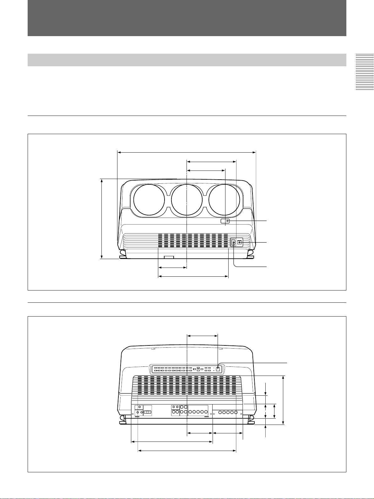
Necessary Clearance for Installation and Maintenance
Make sure to provide enough room for maintenance service. Install the
projector, making reference to the dimensions below.
There should be a space of at least 30 cm (1
ventilation holes. Never block the holes with any material.
Front
603 (23 3/4)
214 (8 7/16)
164.7 (6 15/32)
)
32
/
19
3
/16 inches) around the
Remote control detector
Installation
Rear
345 (13
125 (4 29/32)
302 (11 7/8) (Ventilation holes)
133 (5 1/4)
110 (4 11/32)
350 (13 25/32)
424 (16 11/16) (Ventilation holes)
128 (5 1/32)
MAIN POWER switch
AC IN socket
)
32
/
(1
59.4
)
32
/
11
(2
)
16
/
15
125.8 (4
27
13
35.5
)
16
/
1
(1
Unit: mm (inches)
Error code window/
Remote control detector
Unit: mm (inches)
Installation 5 (GB)
Page 6
Installation Diagrams
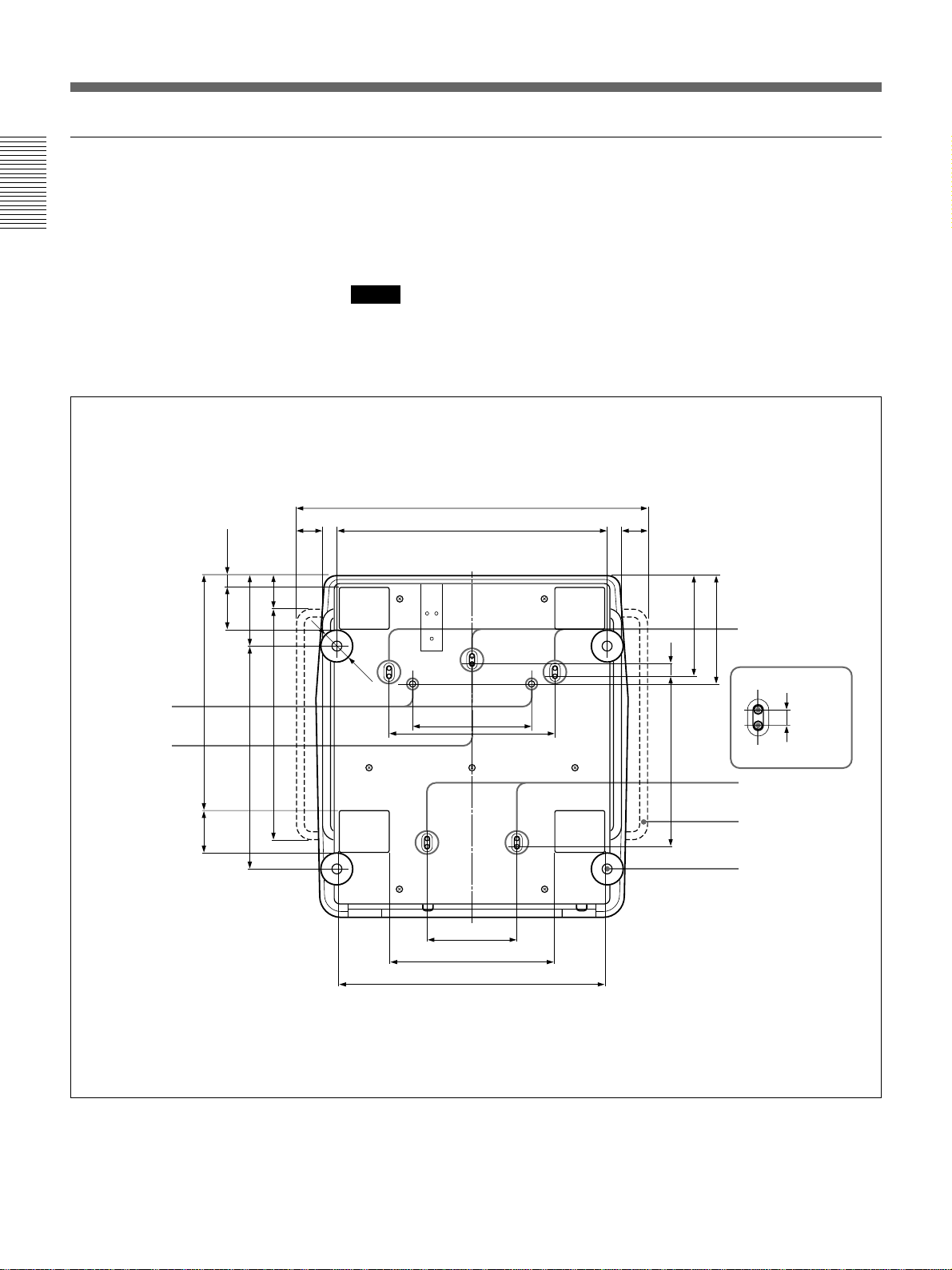
Bottom
Installation
The standard hole for installation on the bottom surface is useful for
reference when measuring for installation. There are seven holes on the
bottom surface of the projector. For ceiling installation using the optional
PSS-70 Projector Suspension Support, use five holes to attach the PSS-70.
The other two holes are spare ones.
Notes
• Use only the M8 meter screws of 10 mm (13/
inches) to 30 mm (1 3/
32
long for the attachment holes for the PSS-70.
• When attaching the PSS-70, use the M8 meter screws of 20 mm (
supplied with the PSS-70.
inches)
16
25
/32 inches)
Receptacles for
the projections
of the PSS-70
Standard hole
for installation
)
32
/
29
22.8 (
)
32
/
9
)
32
83 (3
/
1
457.8 (18
)
32
/
9
83 (3
)
16
/
7
137.8 (5
)
4
/
3
)
8
/
1
451 (17
435 (17
)
16
/
9
64.8 (2
50 (1 31/32)
Ø 60
679 (26 23/32)
524 (20 5/8)
230 (9 1/16)
174 (6 27/32)
318 (12 17/32)
515 (20 9/32)
322 (12 11/16)
50 (1 31/32)
)
32
/
21
11
194.6
(7
)
32
/
31
25 (
)
32
/
1
330.7 (13
)
Holes for attaching
32
/
the PSS-70/spare
holes (M8 meter
screws, 20 mm
(25/32 inches))
211.8 (8
Spare holes
Holes for attaching
the PSS-70
Holes for attaching the
PSS-70/Spare holes
Handle
Adjuster
)
16
/
9
14 (
6 (GB) Installation
Unit: mm (inches)
Page 7
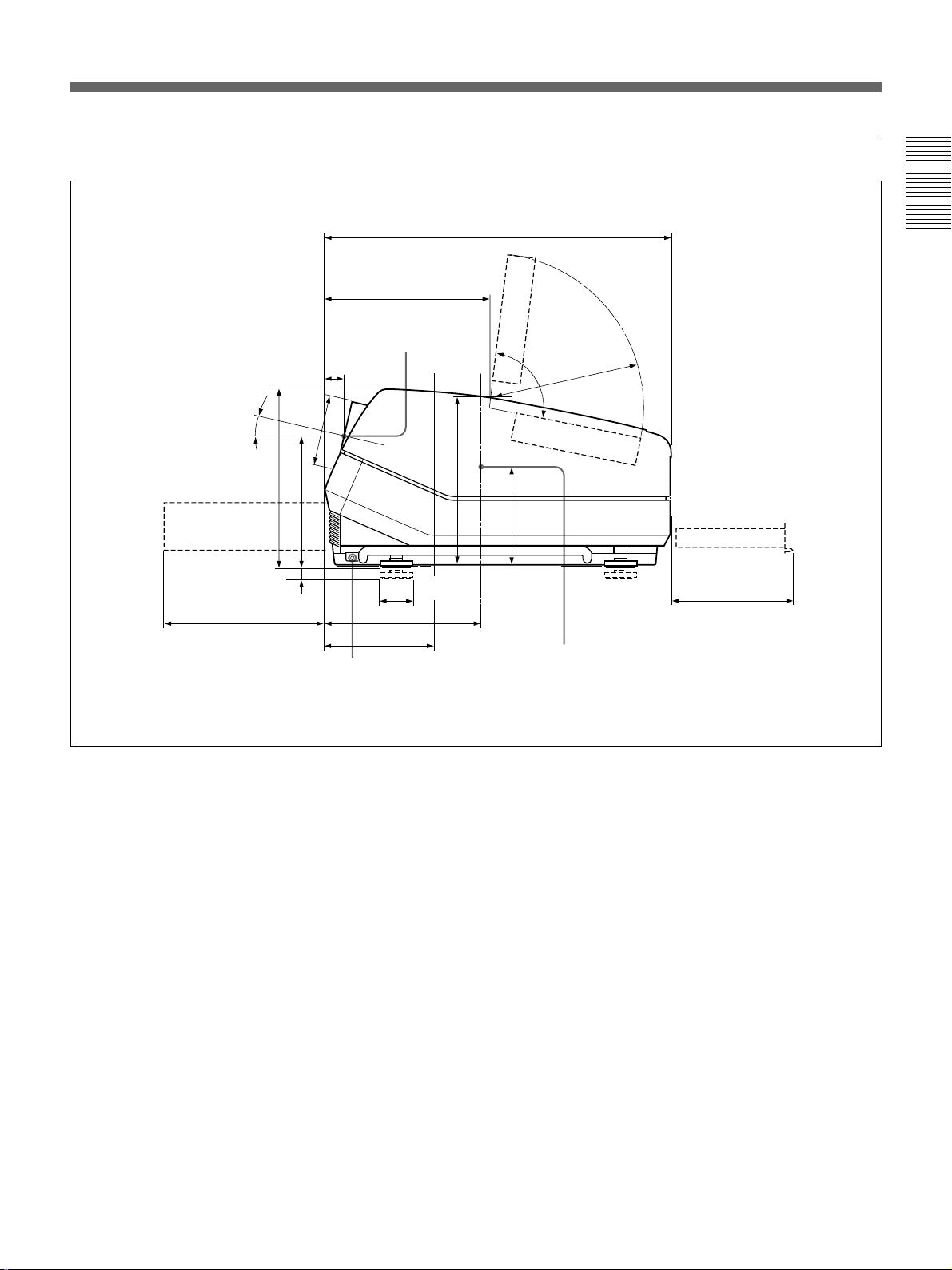
Side
Power supply/
High voltage
circuit block
311.2 (12 1/4)
38
(11/2)
)
32
/
12.5°
∅137
)
32
/
19
345 (13
254 (10)
)
32
/
20
25
(
13
(5
Handle release lever
319 (12 5/8)
Center of the
green lens
∅60 (2 3/8)
301.7 (11 7/8)
169.6 (6 11/16)
Location of the
standard hole
for installation
671 (26 13/32)
329 (13)
Deflection
board
95°
R298 (11
)
16
/
1
154
(6
Center of the gravity
of the projector
)
23
32
/
Adjuster
Installation
Signal board
235.7 (9 9/32)
Unit: mm (inches)
Installation 7 (GB)
Page 8
Installation Diagrams
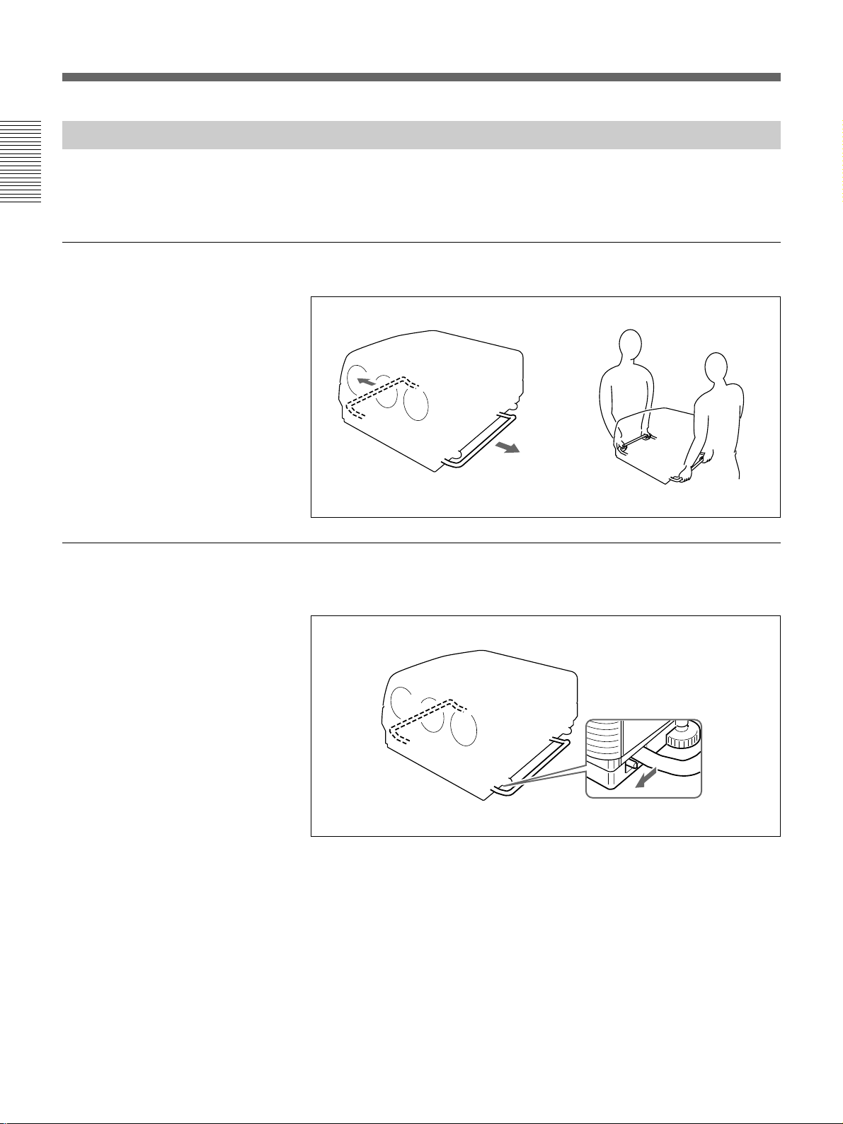
Using the Handles to Carry the Projector
Installation
Using the handles
You can carry the projector by using the side (right and left) handles.
Taking out the unit from the carton or moving the unit requires more than
one person.
Pull out the side handles.
Putting away the handles
Pull the handle release lever under each handle towards you. The handle is
automatically retracted.
8 (GB) Installation
Page 9
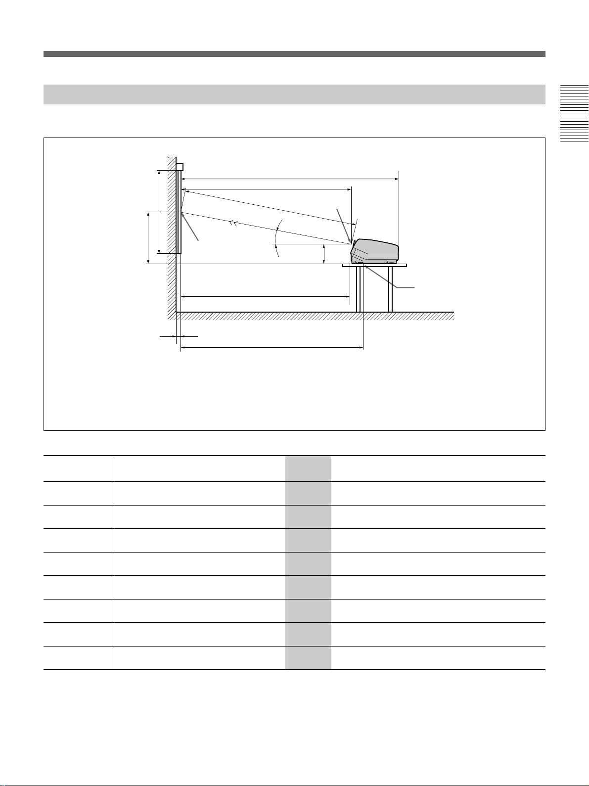
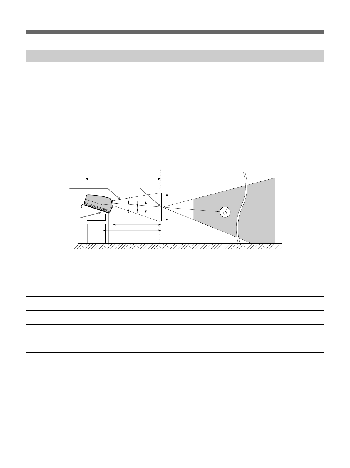
Floor Installation Using Front Projection Flat Screen
Be sure that the projector is level to the floor.
Wall
G
A
B
Center of the screen
C
B: Difference in height between the projector’s bottom surface and the center of the screen
E: Horizontal distance between the center of the screen and the center of the green lens
F: Horizontal distance between the center of the screen and the standard hole for installation
Tolerances
E
D
13.5˚
H
B: ±5%
Other measurements: 0% to +5%
Center of the
green lens
254 (10 )
F
Standard hole
for installation
Floor
Installation
Screen with 4:3 aspect ratio
Screen size
60 70 80 90 100 120 150 180 200 250
The distances in gray are the factory preset settings. Unit:mm (inches)
(inches)
A (Vsize) 914 1067 1219 1372 1524 1829 2286 2743 3048 3810
(36) (42) (48) (54) (60) (72) (90) (108) (120) (150)
B (Hcent) 710 777 845 912 980 1114 1320 1526 1662 2005
(28) (30 5/8) (33 3/8) (36) (38 5/8) (43 7/8) (52) (60 1/8) (65 1/2) (79)
C (Width)
28a)32
b)
32
c)
(1 1/8) (1 5/16) (1 5/16)
D (TD) 1956 2240 2529 2816 3102 3673 4551 5425 6012 7466
(77) (88 1/4) (99 5/8) (110 7/8) (122 1/4) (144 5/8) (179 1/4) (213 5/8) (236 3/4) (294)
E (Xlens) 1902 2179 2459 2738 3016 3571 4424 5274 5844 7257
(74 7/8) (85 7/8) (96 7/8) (107 7/8) (118 7/8) (140 5/8) (174 1/4) (207 5/8) (230 1/8) (285 3/4)
F (Lhole) 2033 2310 2591 2869 3148 3703 4556 5405 5976 7389
(80 1/8) (91) (102) (113) (124) (145 7/8) (179 3/8) (212 7/8) (235 3/8) (291)
G (Lmax) 2535 2812 3092 3371 3649 4204 5057 5907 6477 7890
(99 7/8) (110 3/4) (121 3/4) (132 3/4) (143 3/4) (165 5/8) (199 1/8) (232 5/8) (255 1/8) (310 3/4)
H (Lfront) 1864 2141 2421 2700 2978 3533 4386 5236 5806 7219
(73 1/2) (84 3/8) (95 3/8) (106 3/8) (117 3/8) (139 1/8) (172 3/4) (206 1/4) (228 5/8) (284 1/4)
a) Sony VPS-80FH and VPS-100FH
b) Sony VPS-100FM
c) Sony VPS-120FH and VPS-120FM
Installation 9 (GB)
Page 10
Installation Diagrams
Screen with 16:9 aspect ratio
Screen size
(inches)
Installation
A (Vsize) 747 872 996 1121 1245 1494 1868 2241 2490
B (Hcent) 746 820 893 967 1040 1188 1412 1636 1785
D (TD) 2109 2421 2734 3047 3358 3988 4942 5897 6532
E (Xlens) 2050 2354 2659 2962 3265 3877 4804 5733 6350
F (Lhole) 2182 2486 2791 3094 3397 4009 4936 5865 6482
G (Lmax) 2683 2987 3292 3595 3898 4510 5437 6366 6983
H (Lfront) 2012 2316 2621 2924 3227 3839 4766 5695 6312
(29 1/2) (34 3/8) (39 1/4) (44 1/4) (49 1/8) (58 7/8) (73 5/8) (88 1/4) (98 1/8)
(29 3/8) (32 3/8) (35 1/4) (38 1/8) (41) (46 7/8) (55 5/8) (64 1/2) (70 3/8)
(83 1/8) (95 3/8) (107 3/4) (120) (132 1/4) (157) (194 5/8) (232 1/4) (257 1/4)
(80 3/4) (92 3/4) (104 3/4) (116 5/8) (128 5/8) (152 5/8) (189 1/4) (225 3/4) (250)
(86) (98) (109 7/8) (121 7/8) (133 3/4) (157 7/8) (194 3/8) (231) (255 1/4)
(105 3/4) (117 5/8) (129 5/8) (141 5/8) (153 1/2) (177 5/8) (214 1/8) (250 3/4) (275)
(79 1/4) (91 1/4) (103 1/4) (115 1/8) (127 1/8) (151 1/4) (187 3/4) (224 1/4) (248 1/2)
Unit:mm (inches)
60 70 80 90 100 120 150 180 200
10 (GB) Installation
Page 11
When the Screen Size is not Mentioned in the Tables
You can calculate the installation measurements described below when you
use the screen whose size is not mentioned in the tables on pages 9 (GB),
10 (GB) and 12 (GB), 13 (GB).
Check your installation conditions:
• Screen size to be used (S)
• Installation measurements at the end of the manual, EL and BL for larger
screen size and ES and BS for smaller screen size
See the tables on pages 105 (GB) to 113 (GB).
B
Center of the screen
Installation
Center of the green lens
E
E: Projection distance
B: Screen heights
Now you can calculate the installation measurements as follows:
E (mm) = ES + ((S – smaller screen size) × (EL – ES) × 0.1)
B (mm) = BS + ((S – smaller screen size) × (BL – BS) × 0.1) + 254
Example: when using 124-inch screen
According to the tables on pages 106 (GB) and 107 (GB), the values E and
B are as follows:
ES = 3571, BS = 860 (As the smaller screen size is 120 inch.)
EL = 3856, BL = 929 (As the smaller screen size is 130 inch.)
Therefore,
E (mm) = 3571 + ((124 –120) × (3856 – 3571) × 0.1) = 3685 (mm)
B (mm) = 860 + ((124 – 120) × (929 – 860) × 0.1) + 254 = 1142 (mm)
Installation 11 (GB)
Page 12
Installation Diagrams
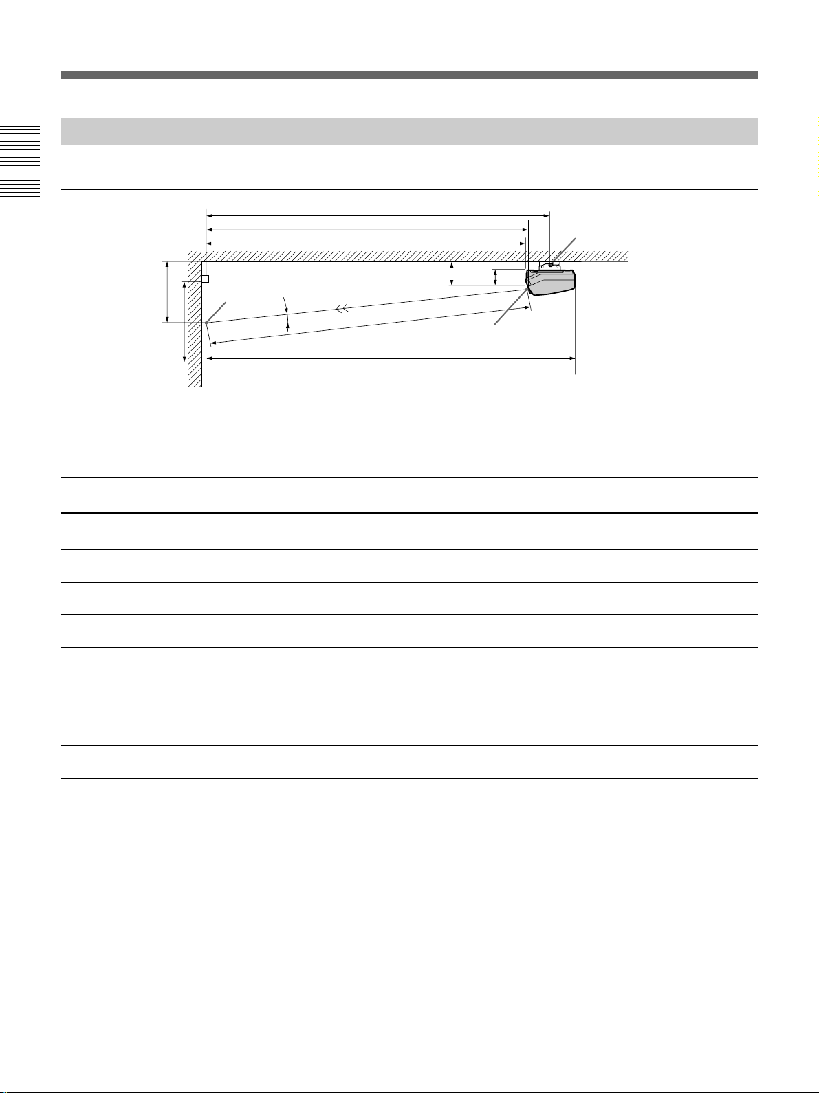
Ceiling Installation Using Front Projection Flat Screen
Use the PSS-70 Projector Suspension Support (not supplied).
Installation
B
A
Wall
Screen with 4:3 aspect ratio
Screen size
(inches)
A (Vsize) 914 1067 1219 1372 1524 1829 2286 2743 3048 3810
B (Hcent) 825 892 960 1027 1094 1229 1435 1640 1777 2120
(32 1/2) (35 1/8) (37 7/8) (40 1/2) (43 1/8) (48 3/8) (56 1/2) (64 5/8) (70) (83 1/2)
D (TD) 1956 2240 2529 2816 3102 3673 4551 5425 6012 7466
E (Xlens) 1902 2179 2459 2738 3016 3571 4424 5274 5844 7257
(74 7/8) (85 7/8) (96 7/8) (107 7/8) (118 7/8) (140 5/8) (174 1/4) (207 5/8) (230 1/8) (285 3/4)
F’ (Lpss) 2166 2442 2723 3001 3280 3835 4688 5537 6108 7521
(85 3/8) (96 1/4) (107 1/4) (118 1/4) (129 1/4) (151) (184 5/8) (218 1/8) (240 1/2) (296 1/8)
G (Lmax) 2535 2812 3092 3371 3649 4204 5057 5907 6477 7890
(99 7/8) (110 3/4) (121 3/4) (132 3/4) (143 3/4) (165 5/8) (199 1/8) (232 5/8) (255 1/8) (310 3/4)
H (Lfront) 1864 2141 2421 2700 2978 3533 4386 5236 5806 7219
(73 1/2) (84 3/8) (95 3/8) (106 3/8) (117 3/8) (139 1/8) (172 3/4) (206 1/4) (228 5/8) (284 1/4)
Center of
the screen
F’
E
H
369(14 5/8)
13.5˚
D
G
E: Horizontal distance between the center of the screen and the center of the green lens
Tolerances
B: ±5%
Other measurements: 0% to +5%
254(10)
Center of the green lens
Rotation axis of
the PSS-70
Ceiling
Unit:mm (inches)
60 70 80 90 100 120 150 180 200 250
(36) (42) (48) (54) (60) (72) (90) (108) (120) (150)
(77) (88 1/4) (99 5/8) (110 7/8) (122 1/4) (144 5/8) (179 1/4) (213 5/8) (236 3/4) (294)
12 (GB) Installation
Necessary parts modifications
Changing the polarity used for “Ceiling installation, front projection”
For details, see “Changing the Polarity” on page 20 (GB).
Page 13
Screen with 16:9 aspect ratio
Screen size
(inches)
A (Vsize) 747 872 996 1121 1245 1494 1868 2241 2490
B (Hcent) 861 935 1008 1082 1155 1303 1527 1751 1900
D (TD) 2109 2421 2734 3047 3358 3988 4942 5897 6532
E (Xlens) 2050 2354 2659 2962 3265 3877 4804 5733 6350
F’ (Lhole) 2314 2618 2923 3226 3529 4141 5068 5997 6614
G (Lmax) 2683 2987 3292 3595 3898 4510 5437 6366 6983
H (Lfront) 2012 2316 2621 2924 3227 3839 4766 5695 6312
60 70 80 90 100 120 150 180 200
(29 1/2) (34 3/8) (39 1/4) (44 1/4) (49 1/8) (58 7/8) (73 5/8) (88 1/4) (98 1/8)
(34) (36 7/8) (39 3/4) (42 5/8) (45 1/2) (51 3/8) (60 1/8) (69) (74 7/8)
(83 1/8) (95 3/8) (107 3/4) (120) (132 1/4) (157) (194 5/8) (232 1/4) (257 1/4)
(80 3/4) (92 3/4) (104 3/4) (116 5/8) (128 5/8) (152 5/8) (189 1/4) (225 3/4) (250)
(91 1/8) (103 1/8) (115 1/8) (127 1/8) (139) (163 1/8) (199 5/8) (236 1/8) (260 1/2)
(105 3/4) (117 5/8) (129 5/8) (141 5/8) (153 1/2) (177 5/8) (214 1/8) (250 3/4) (275)
(79 1/4) (91 1/4) (103 1/4) (115 1/8) (127 1/8) (151 1/4) (187 3/4) (224 1/4) (248 1/2)
Unit:mm (inches)
Installation
Installation 13 (GB)
Page 14
Installation Diagrams
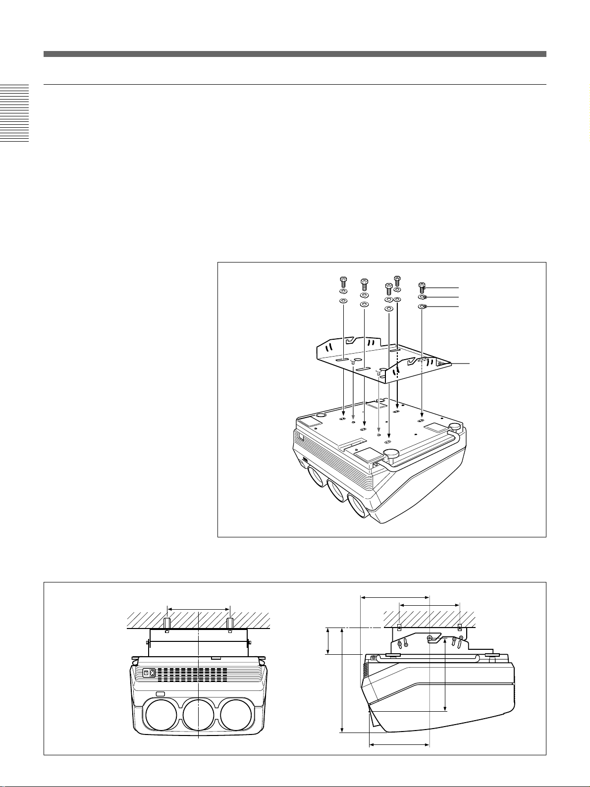
Attaching the PSS-70 Projector Suspension Support
Attach the projector mounting bracket to the bottom surface of the
projector.
Installation
Use five each of the M8×20 bolts, M8 washers and spring washers, all of
which are supplied with the PSS-70.
1 Align the two projections on the projector mounting bracket with the
receptacles on the bottom surface of the projector.
2 Fasten the five bolts and washers to fix the mounting bracket to the
five holes for attaching the PSS-70 on the bottom surface of the
projector.
M8×20 bolt
Spring washer
M8 washer
Installation dimensions
254 (10)
Projector
mounting
bracket
For attaching the PSS-70 to the ceiling, refer to the Installation Manual of the
PSS-70 Projector Suspension Support.
301.8 (11 7/8)
)
32
/
17
254
(10)
14 (GB) Installation
114.8 (14
457.4 (18)
263.8 (10 3/8)
)
16
/
11
322.5
(12
Page 15
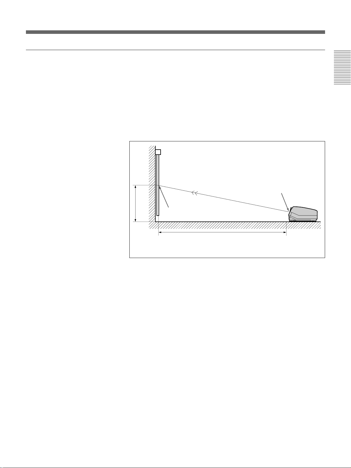
Floor Installation Using Rear Projection Flat Screen
What is the optical axis angle?
The optical axis angle is the angle between the horizontal level line and the
straight line from the center of the projector’s green lens to the center of
the screen. When using a rear projection screen, you can get the brightest
picture when the center of the screen is aligned with a straight line
extension of the center of the green lens.
Therefore, the most suitable optical axis angle varies depending on the
height of the screen and your line of sight.
When the optical axis angle is 2°
Wall
G
Optical axis
angle
15.5°
Standard hole for
installation
Center of the screen
2°
E
F
–
B
0
+
A
Installation
Floor
Screen with 4:3 aspect ratio
Screen size
(inches)
A (Vsize) 914 1067 1219 1372 1524 1829 2286 2743 3048 3810
B (Hcent) 140 130 120 110 100 80 49 18 -3 -54
E (Xlens) 1977 2265 2556 2846 3136 3712 4599 5482 6075 7544
F (Lhole) 2172 2460 2751 3041 3331 3907 4794 5677 6270 7739
G (Lmax) 2655 2943 3234 3524 3814 4390 5277 6160 6753 8222
60 70 80 90 100 120 150 180 200 250
(36) (42) (48) (54) (60) (72) (90) (108) (120) (150)
(5 5/8) (5 1/4) (4 3/4) (4 3/8) (4) (3 1/4) (1 15/16)(23/32)(-
(77 7/8) (89 1/4) (100 3/4) (112 1/8) (123 1/2) (146 1/4) (181 1/8) (215 7/8) (239 1/4) (297 1/8)
(85 5/8) (96 7/8) (108 3/8) (119 3/4) (131 1/8) (153 7/8) (188 3/4) (223 5/8) (246 7/8) (304 3/4)
(104 5/8) (115 7/8) (127 3/8) (138 3/4) (150 1/4) (172 7/8) (207 7/8) (242 5/8) (265 7/8) (323 3/4)
Unit: mm (inches)
1
/8) (-2 1/8)
Necessary parts modifications
Changing the polarity used for “Floor installation, rear projection”
For details, see “Changing the Polarity” on page 20 (GB).
Installation 15 (GB)
Page 16
Installation Diagrams
Screen with 16:9 aspect ratio
Screen size
(inches)
A (Vsize) 747 872 996 1121 1245 1494 1868 2241 2490
Installation
B (Hcent) 135 124 113 102 91 69 35 1 –21
E (Xlens) 2132 2447 2764 3079 3394 4030 4994 5960 6601
F (Lhole) 2327 2642 2959 3274 3589 4225 5189 6155 6796
G (Lmax) 2810 3125 3442 3757 4072 4708 5672 6638 7279
(29 1/2) (34 3/8) (39 1/4) (44 1/4) (49 1/8) (58 7/8) (73 5/8) (88 1/4) (98 1/8)
(5 3/8) (5) (4 1/2) (4 1/8) (3 5/8) (2 3/4) (1 7/16)(
(84) (96 3/8) (108 7/8) (121 1/4) (133 5/8) (158 3/4) (196 3/4) (234 3/4) (260)
(91 5/8) (104 1/8) (116 1/2) (129) (141 3/8) (166 3/8) (204 3/8) (242 3/8) (267 5/8)
(110 5/8) (123 1/8) (135 5/8) (148) (160 3/8) (185 3/8) (223 3/8) (261 3/8) (186 5/8)
60 70 80 90 100 120 150 180 200
1
/16)(–27/32)
Unit:mm (inches)
16 (GB) Installation
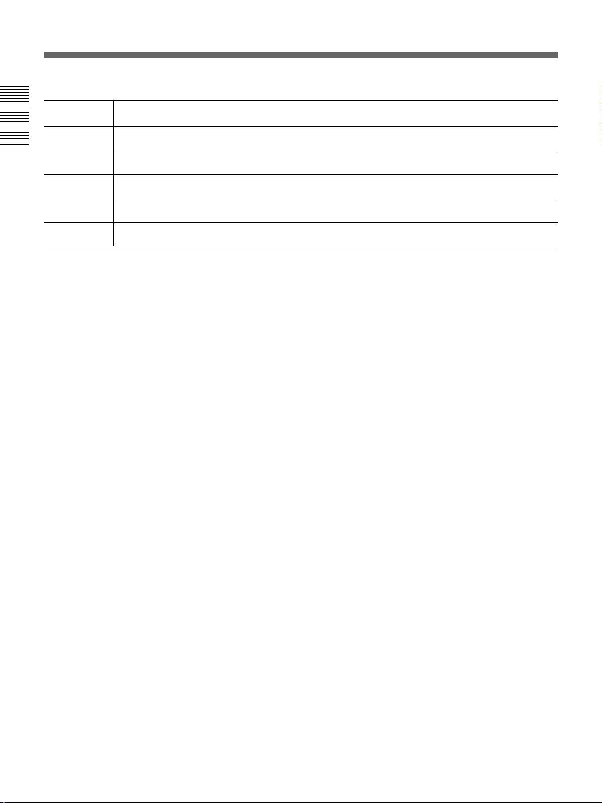
Page 17
Variable Range of the Optical Axis Angle in Rear Projection
You can change the optical axis angle within the following ranges by
adjusting flapping of the lens.
For adjusting flapping of the lens, see “Adjusting flapping of the green lens” on
page 62 (GB).
On floor installation
You can install the projector within an angle of optical axis –13.5° to +2°.
Wall
+2°
–13.5°
Installation
n : Optical axis
– · – · : Horizontal line
Floor
On ceiling installation
You can install the projector within an angle of optical axis +3° to +13.5°.
Ceiling
+13.5°
+3°
Wall
n : Optical axis
– · – · : Horizontal line
Installation 17 (GB)
Page 18
Installation Diagrams
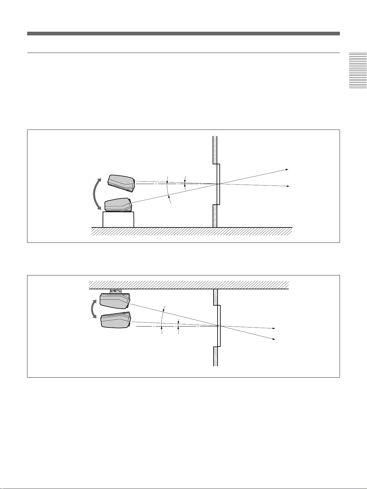
Notes on Screen
Screen size
Installation
The screen size is the diagonal length of the screen in
inches, while the aspect ratio of the screen is 4:3. The
ratio of the screen width, height, and diagonal is 4:3:5.
4
3
If you use a screen with 4:3 aspect ratio whose size is
not given in the table below, you can calculate the
screen height and width from the screen size (inches)
as follows.
Calculate at the conversion rate of 25.4 mm to the
inch.
Height (mm) = Screen size × 25.4 ×
Width (mm) = Screen size × 25.4 ×
Screen size and dimensions
Screen size (inches)
(Diagonal) Height (mm) Width (mm)
60 914 1219
70 1067 1422
80 1219 1626
90 1372 1829
100 1524 2032
120 1829 2438
150 2286 3048
180 2743 3658
200 3048 4064
250 3810 5080
5
3
/5
4
/5
Screens with an aspect ratio other than
4:3
When the height is greater
Calculate the screen size with 4:3 aspect ratio from the
screen height as shown below. Install the projector and
screen in accordance with the screen size obtained.
--- : Screen whose aspect
ratio is 4:3
5
1
/3) ×
/4) ×
1
/25.4
/25.4
Screen size (inch) = (height (mm) ×
Example: When the screen height is 1500 mm
5
1
/3) ×
(1500 (mm) ×
/25.4 = Approx. 98 inches
When the width is greater
Calculate the screen size with 4:3 aspect ratio from the
screen width as shown below. Install the projector and
screen in accordance with the screen size obtained.
---: Screen whose aspect
ratio is 4:3
Screen size (inch) = (width (mm) ×
5
Example: When the screen width is 2000 mm
5
1
/4) ×
(2000 (mm) ×
/25.4 = Approx. 98 inches
Screen with 16:9 aspect ratio
Screen size (inches)
(Diagonal) Height (mm) Width (mm)
60 747 1328
70 872 1549
80 996 1771
90 1121 1992
100 1245 2214
120 1494 2656
150 1868 3320
180 2241 4572
200 2490 4427
18 (GB) Installation
Page 19
Types of screen
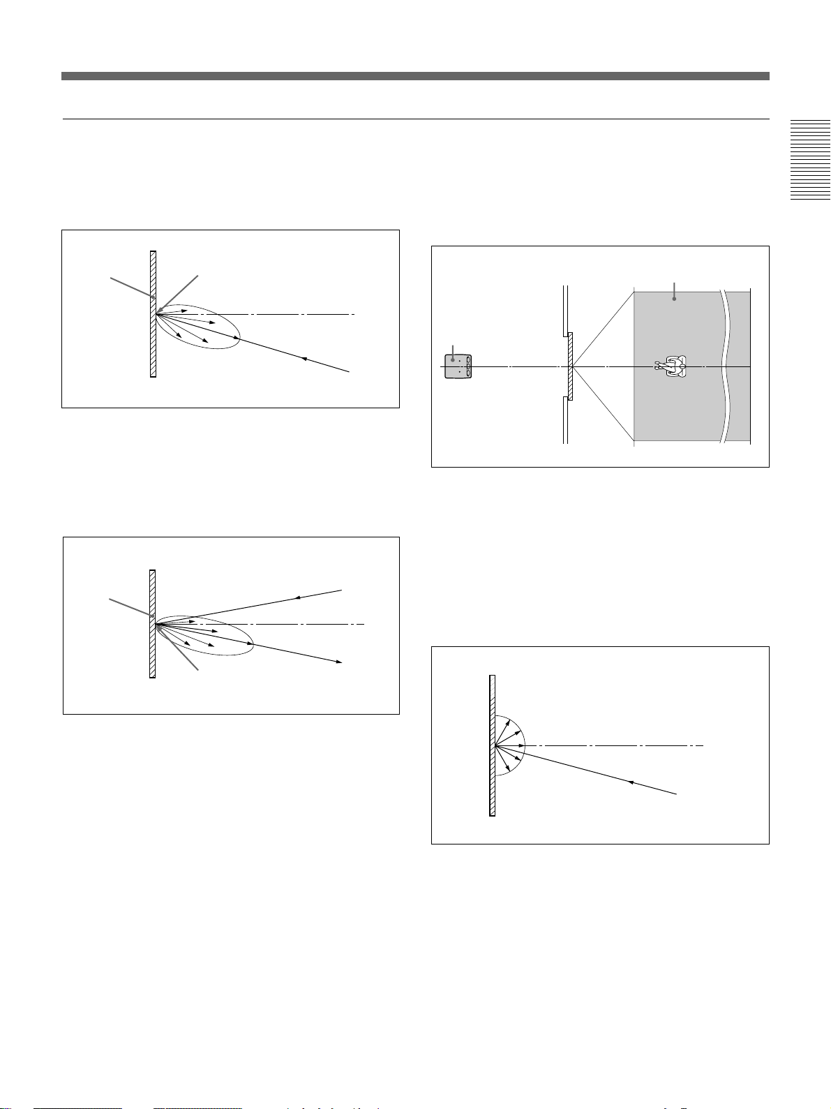
Front projection screen for floor installation
The bead screen is recommended. A screen of this type
reflects the brightest light.
Bead screen
Center of the screen
Brightest picture
Projector
Front projection screen for ceiling installation
The silver screen is recommended. You can get a
picture that is two to four times brighter than that of
the white screens.
Projector
Silver
screen
Rear projection screen
A screen manufactured using two sheets, the fresnel
and lenticular, is recommended for a bright and clear
full-screen picture projection.
Horizontal viewing areaScreen
Projector
White screen
When viewers watch the projected picture in a wide
area, you can obtain a picture that appears equally
bright from all parts of the room using the white
screen for both floor and ceiling installations. Note
that you will not be able to get a clear picture in this
case unless the room is dark.
Installation
Center of the screen
Brightest picture
Projector
Installation 19 (GB)
Page 20

Modifying Parts
Removing the Upper Cover
1 Turn off the main power of the projector.
Installation
2 Unlock the two screws on the projector by using a screwdriver or a
coin edge, and then open the upper cover.
Locked Unlocked
3 Slide the upper cover towards the rear and lift it to remove.
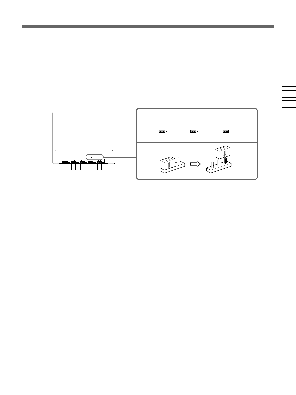
Changing the Polarity
20 (GB) Installation
The polarity of the projector is adjusted to use the projector for front
projection on the floor.
When the projector is installed on the ceiling or used in rear projection, it
is necessary to change the settings of the polarity switch and the polarity
connectors.
Page 21
How to change the polarity
1 Turn off the power of the projector.
2 Remove the upper cover.
For how to remove the upper cover, see page 20 (GB).
3 Press to open the connector cover.
4 Check the polarity switch position and the connecting position of the
polarity connectors.
For the installation methods of the projector and the settings of the switch and
the connectors, see the diagram on the next page.
Installation
Polarity switch position
Lens side
(Factorypreset)
Board
side
Connector cover
Connecting position of
the polarity connectors
Lens side
(Factory-preset)
Board side
5 Change the switch position and/or the connecting position of the
connectors, if necessary.
Polarity switch: Set to the lens side or board side position.
Polarity connectors: Disconnect the three connectors, then turn them
over (180°) and reinsert into the receptacles on the lens side or the
board side.
6 Make sure to insert the connectors correctly and to set the switch to the
correct position, then restore the connector cover and the upper cover.
Note
If the connector cover does not shut firmly, the power of the projector is not turned
on.
Installation 21 (GB)
Page 22
Modifying Parts
Installation methods and settings of the polarity switch and the polarity connectors
Installation
Polarity and on-screen display
Installation
methods
Front projection,
Position of the
switch
L
Connecting
position of the
connectors
L
On-screen display
by default (See
below.)
Correct
floor
Front projection,
B
B
C
ceiling
Rear projection,
L
B
A
floor
Rear projection,
B
L
B
ceiling
Others
Display letters on the screen so that you can determine
which changes to make.
For on-screen display and necessary changes, see below.
L: Lens side
B: Board side
Note
When installing the projector, make sure to leave space of more than 30 cm (12
inches) between the wall or floor and the ventilation holes of the projector.
When the projector is installed on the ceiling or used in rear projection
without changing the polarity, one of the following on-screen displays
appears. In this case, you have to change the polarity corresponding to the
installation methods.
A The letters are backward.
Change the connecting position of
the polarity connectors.
INPUT-A
For optimum
performance,
white screen will
remain for 20min.
For immediate use,
push [MENU] key.
B The letters are upside
down.
Change the polarity switch position.
push [MENU] key.
For immediate use,
remain for 20min.
white screen will
performance,
For optimum
INPUT-A
C The letters are upside down and backward.
Change the polarity switch position and the connecting position of the
polarity connectors.
push [MENU] key.
For immediate use,
remain for 20min.
white screen will
performance,
For optimum
INPUT-A
22 (GB) Installation
Page 23
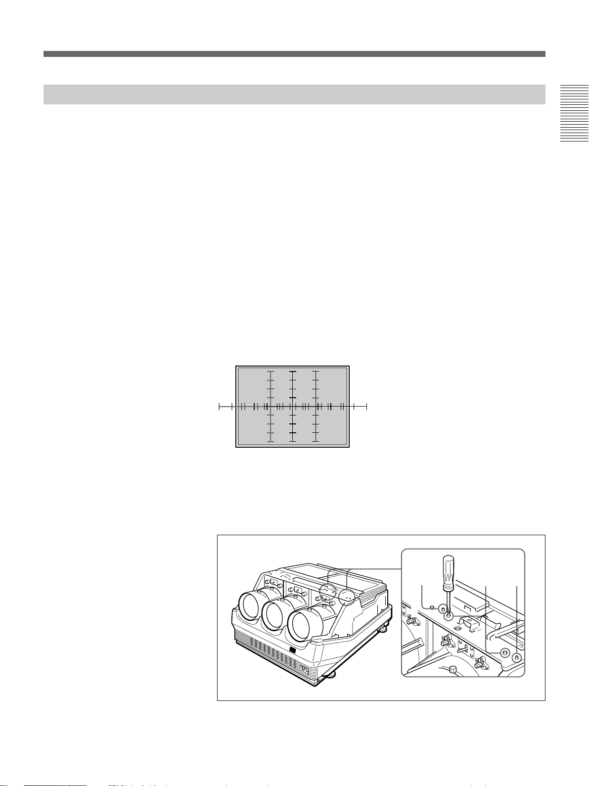
Adjusting the CRT Conversion Angle
Adjust the CRT conversion angle so that the three CRT images converge
exactly.
1 Remove the upper cover.
For how to remove the upper cover, see page 20 (GB).
2 Turn on the power of the projector.
3 Set the remote control to the service adjustment mode.
For details, see “Preparation” on page 35 (GB).
4 Reset the green, red and blue centering.
For details, see “Resetting the Data” on page 99 (GB).
5 Make sure that the on-screen display is shown as follows:
• The center of the green HATCH pattern aligns with the horizontal
center of the screen.
• The center of the red and blue HATCH patterns align at even
intervals from the green HATCH pattern.
Installation
If the center of the green HATCH pattern does not align with the center
of the screen, re-install the projector correctly.
6 Loosen the four red CRT fixing screws (black) by using the Philips
screwdriver. Make sure not to remove the screws.
Black
screws
Black
screws
Black
screws
(continued)
Installation 23 (GB)
Page 24

Modifying Parts
7 Move the red lens right and left to adjust the CRT conversion angle so
that the vertical line of the red HATCH pattern converges with that of
the green pattern.
Installation
8 When the HATCH pattern aligns with the green pattern correctly,
tighten the four CRT fixing screws loosened in step 6.
9 Repeat steps 6 to 8 to loosen the four blue CRT fixing screws (black),
adjust the blue CRT conversion angle and tighten the four CRT fixing
screws.
24 (GB) Installation
Page 25
Connections
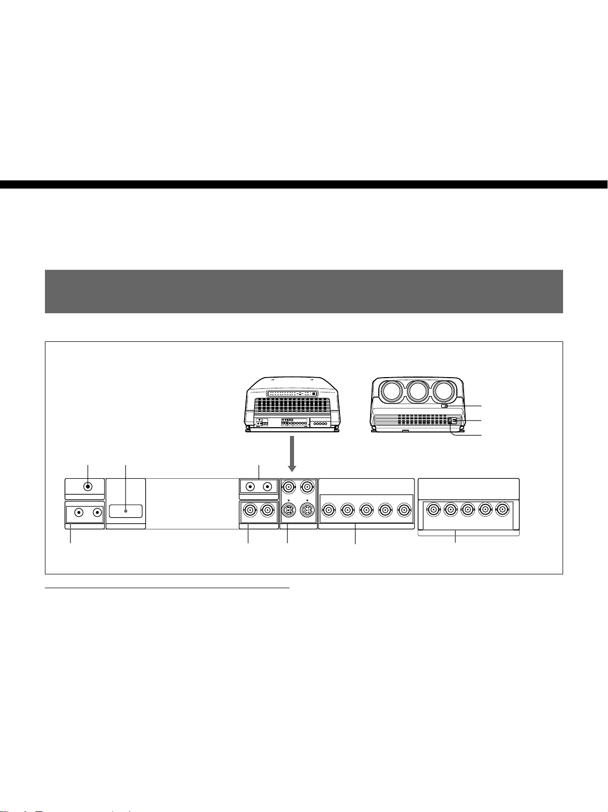
Location and Function of Connectors
Connections
1
TRIGGER
IN OUT
PLUG IN POWER
CONTROL S
2
RS-422A
REMOTE
3
IN OUT
ABL LINK
IN IN
VIDEO
Rear
1 TRIGGER connector (minijack)
When the projector is turned on, 12 V is output and
when it is turned off, 0 V is output. However, the
connector is not used as the power source since the
power is not output.
Rear
Y IN
S VIDEO
Front
!¡
0
9
C IN
R
OUTOUT
CR/R-Y/P
R
YGCB/B-Y/P
7654
B SYNC/HD VD
B
INPUT A
C
R
R
/R-Y/P
VIDEO
SYNC/HD
G
B
R
B
/B-Y/P
Y
C
C
Y
INPUT B
VD
B
8
3 ABL (Automatic Brightness Limiter) LINK IN/
OUT jacks (minijack)
When connecting multiple projectors, connects the
ABL LINK OUT jack to the ABL LINK IN jack on
another projector. You can synchronize the brightness
limiting point among the projectors, allowing to make
the whole screen brightness uniform.
2 RS-422A REMOTE connector (D-sub 9-pin)
Used to expand the system connections using the RS422A interface.
Before using the connector, remove the red cap.
Connections 25 (GB)
Page 26
Location and Function of Connectors
4 CONTROL S jacks
IN/PLUG IN POWER (5 V) jack (stereo minijack):
Connects to the CONTROL S OUT jack of other
Sony equipment. Also connects to the CONTROL
S OUT jack of the supplied remote control with the
supplied remote control cable (stereo cable) to be
used as a wired remote control. In this case, this
jack supplys 5 V to the remote control as power
source.
OUT jack (stereo minijack): Connects to the
CONTROL S IN jack of other Sony equipment.
Connections
Note
When using this jack, the remote control detector on the
projector does not function.
5 VIDEO IN/OUT connectors
VIDEO IN connector (BNC type): Connects to the
composite video output of the video equipment.
VIDEO OUT connector (BNC type): Connects to
the composite video input of a color monitor.
6 S VIDEO IN/OUT connectors
Y IN, C IN connectors (BNC type): Connects to the
Y and C video outputs of the video equipment.
S VIDEO IN/OUT connectors (4-pin, mini-DIN
type): Connects to the S video output or input
connector of the video equipment.
Front
9 AC IN socket
Connect the supplied AC power cord.
!º MAIN POWER switch
!¡ Front remote control detector
Note
The S VIDEO IN connector is disconnected when a cable
is connected to the Y/C IN connectors.
7 INPUT A connectors (BNC type)
R
/R-Y/PR, G/Y, B/CB/B-Y/PB, SYNC/HD, VD
R/C
connectors: Connect to the video equipment outputs.
According to the connected equipment, the RGB
(R, G, B), component (R-Y, G, B-Y) or HDTV (P
B) signal is selected.
Y, P
R
8 INPUT B connectors (BNC type)
R/R-Y/PR/VIDEO, G/Y Y/Y, B/CB/B-Y/PB/C,
R/C
SYNC/HD, VD connectors: Connect to the video
equipment outputs. According to the connected
equipment, the RGB (R, G, B), component (R-Y,
G, B-Y), HDTV (P
R, Y, PB), S VIDEO, VIDEO
signal is selected.
,
26 (GB) Connections
Page 27
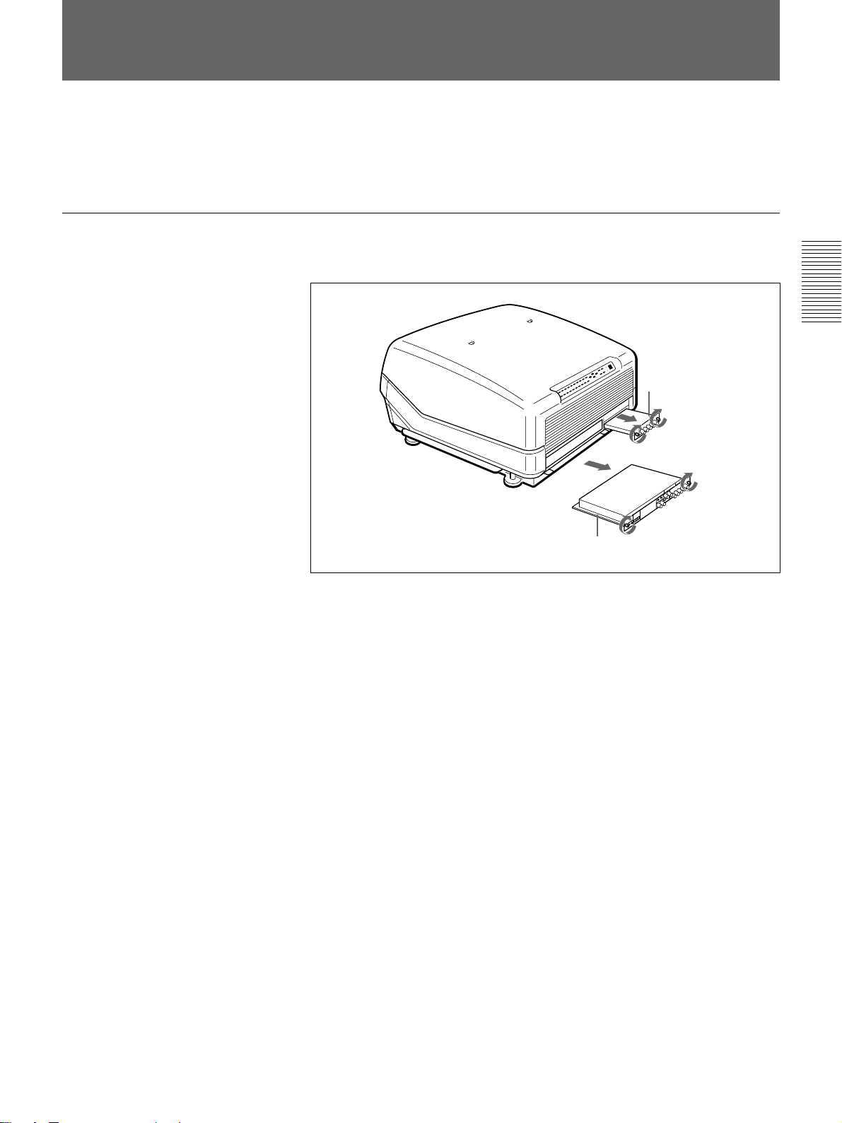
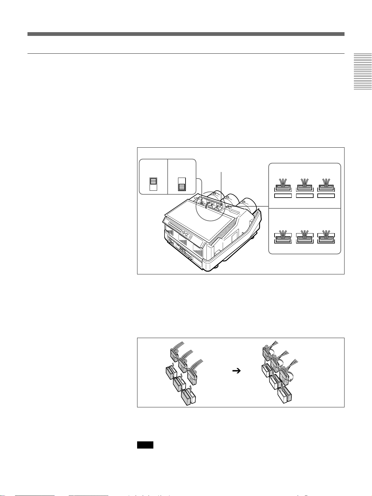
Switching the Connectors
Depending on the connections of the computer and color monitor to the
projector, it may be necessary to switch the 75-ohm terminate connectors
on the A board and the sync 75-ohm terminate connectors and sync
separate connector on the QB board at the rear of the projector.
Removing the A Board
1 Loosen the two screws on each board at the rear of the projector to
remove the connector panel.
Connections
QB board
A board
2 Switch the connectors on the A board and the QB board.
For details, see pages 28 (GB) and 29 (GB).
3 Replace the A board by reversing step 1.
Connections 27 (GB)
Page 28
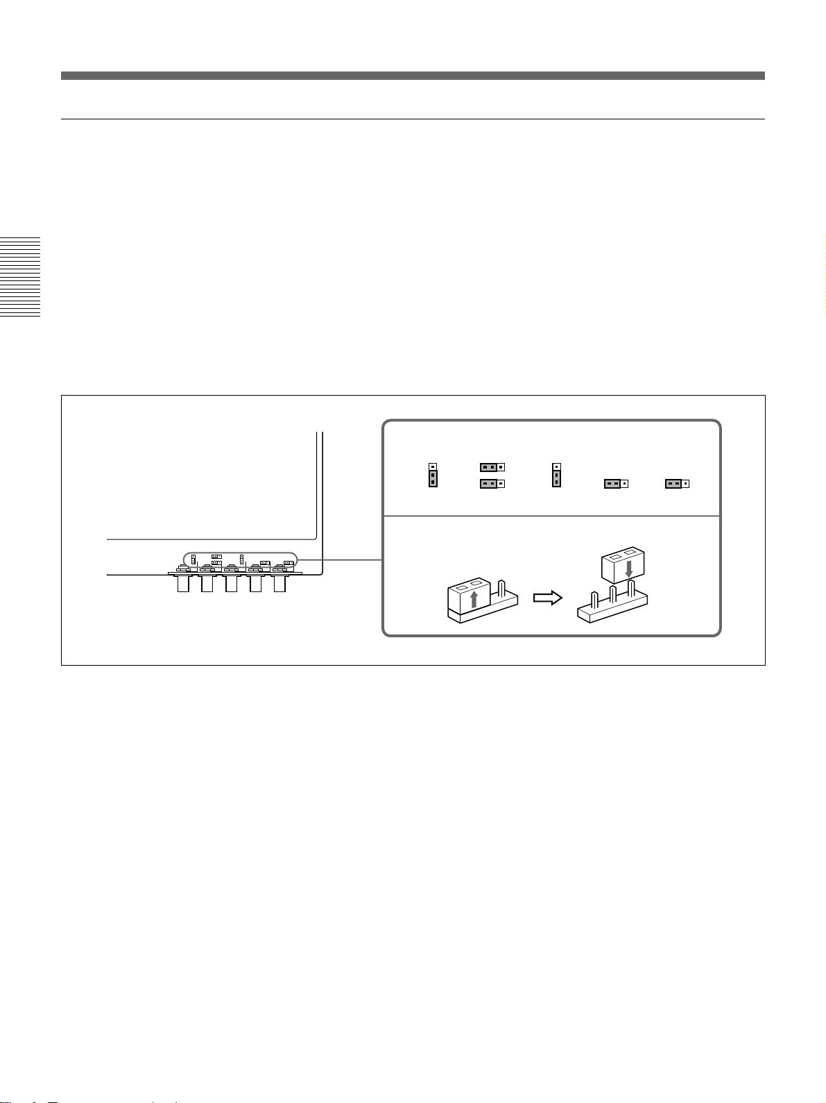
Switching the Connectors
INPUT A: Setting the A board
Connections
CN1001, CN1002 and CN1003 connectors
Sync 75-ohm terminate connector: Normally set to “1K”. Set the
CN1002 and CN1003 to “75” when the sync output signal is terminated
at 75 ohms.
Sync separate connector: Set the CN1001 to change the sync on green
signal to the separate sync signal. Set it to “HS SEP” when the HDTV
external sync signal, etc. is input.
CN1004, CN1005 and CN1006 connectors
75-ohm (pin position 3): This position is selected at the factory.
OPEN (pin position 1): Set to this position when the input signal is
distributed into other equipment using a branch connector and is
terminated at 75 ohms on that equipment.
Pin positions set at the factory
1
OPEN
2
75 75
3
CN1006
CN1001
321
HS HS SEP
NORM
321
CN1005
OPEN
CN1004
1
OPEN
2
75
3
1k 75
123
CN1003
1k 75
123
CN1002
A board
How to switch the connector
1
2
3
1
2
3
28 (GB) Connections
Page 29
INPUT B: Setting the QB board
Sync 75-ohm terminate connector: Normally set to “1K”. Set the CN10
and CN11 to “75” when the sync output signal is terminated at 75 ohms.
Sync separate connector: Set the CN12 to change the sync on green
signal to the separate sync signal. Set it to “HS SEP” when the HDTV
external sync signal, etc. is input.
QB board
Pin positions set at the factory
1k
75
H/C TERM
CN10 CN11
How to switch the connector
1
2
3
123123
1k
75
V TERM
Connections
HS FIX
HS SEP
HS NORM
123
CN12
1
2
3
Connections 29 (GB)
Page 30
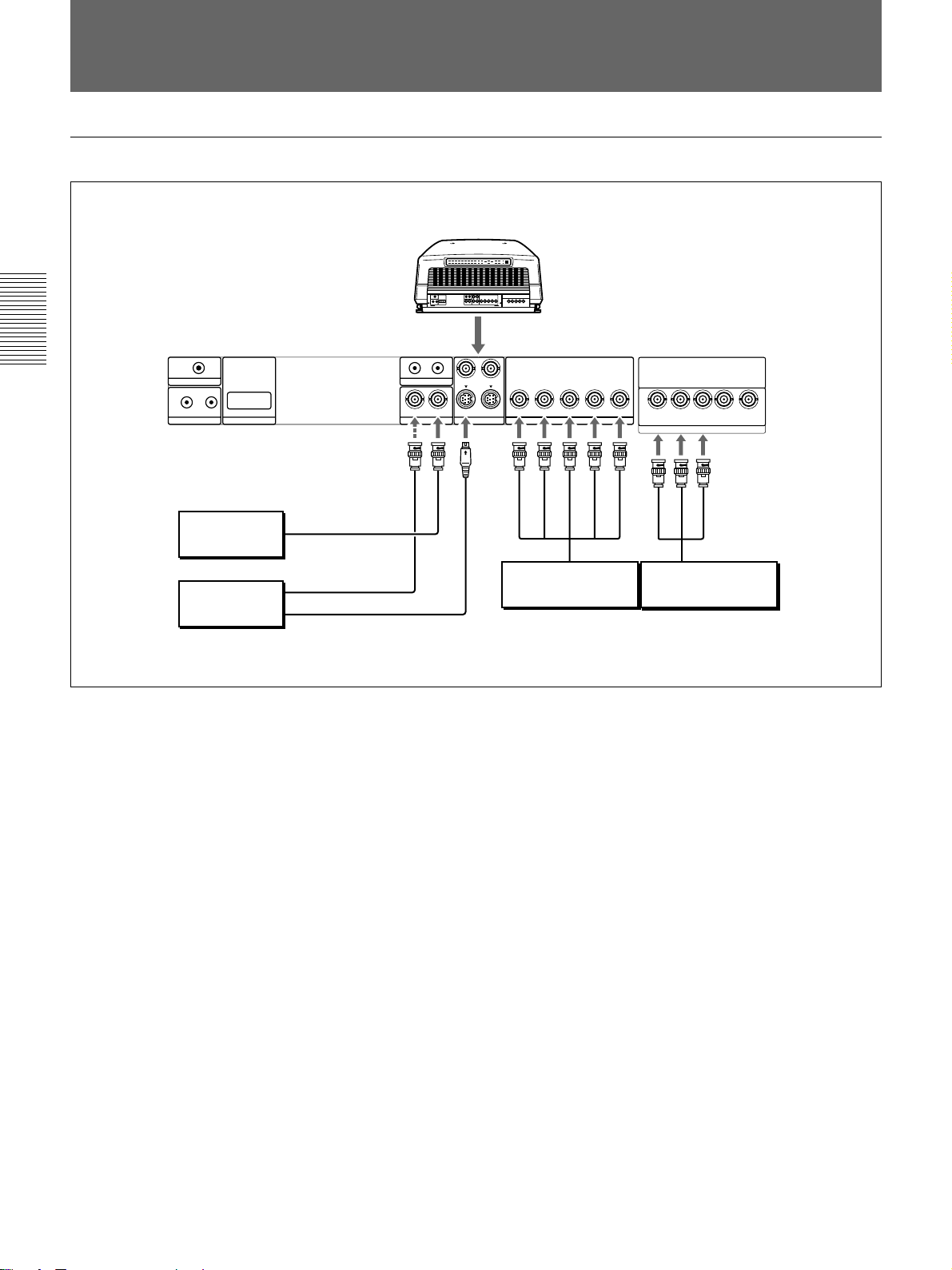
Connecting Directly to the Projector
When multiple input sources are connected to the projector
Rear
Connections
TRIGGER
IN OUT
PLUG IN POWER
CONTROL S
RS-422A
REMOTE
Color monitor
Video equipment
to video input
to video output
to S Video output
Setting up
• Set INPUT-A in the SET SETTING menu to RGB and INPUT-B to
COMPONENT.
For details, see “The SET SETTING Menu” on page 48 (GB).
• Select VIDEO or S VIDEO by pressing the INPUT SELECT keys on the
remote control or by setting VIDEO in the INPUT SELECT menu.
For details, see “The INPUT SELECT Menu” on page 42 (GB).
• Switch the 75-ohm terminate connectors according to the connections of
the computer and color monitor.
For details, see “Switching the Connectors” on page 27 (GB).
IN OUT
ABL LINK
IN
VIDEO
VIDEO IN
Y IN
C IN
OUTOUT
CR/R-Y/PRYCB/B-Y/P
IN
S VIDEO
R
S VIDEO IN
VIDEO OUT
R G B SYNC/HD
B
INPUT A
B
G
SYNC/HD
to RGB output
VD
VD
C
R
R
/R-Y/P
VIDEO
R-Y
SYNC/HD
G
R
B
/B-Y/P
Y
C
Y
INPUT B
VD
B
B
C
Y
B-Y
to component output
Video equipmentVideo equipment
30 (GB) Connections
Page 31

Using the Linked ABL Function
What is linked ABL function?
The ABL (Automatic Brightness Limiter) function is incorporated with the
projector. The ABL function prevents CRT burn by controlling the
brightness of the screen if it becomes too high.
If you connect the ABL LINK jacks of each projector when connecting
multiple projectors to display a malti-screen, the ABL functions on all
projectors once the ABL functions on any one projector. The linked ABL
function allows the malti-screen’s brightness uniform.
Second projector
TRIGGER
IN OUT
PLUG IN POWER
CONTROL S
RS-422A
REMOTE
First projector
TRIGGER
IN OUT
PLUG IN POWER
CONTROL S
RS-422A
REMOTE
Rear
OUT
IN
ABL LINK
IN
VIDEO
OUT
Y IN
IN
S VIDEO
C IN
OUT
ABL LINK IN
Connecting cable with
miniplugs (not supplied)
ABL LINK OUT
IN OUT
ABL LINK
IN
VIDEO
OUT
Y IN
IN
S VIDEO
C IN
OUT
R
CR/R-Y/P
R
CR/R-Y/PRCB/B-Y/P
G
R
Y
G
Y
B SYNC/HD VD
B
/B-Y/P
C
INPUT A
B SYNC/HD VD
INPUT A
Connections
B
C
R
/R-Y/P
VIDEO
R
SYNC/HD
G
R
Y
C
B
/B-Y/P
Y
INPUT B
VD
B
B
C
Video equipment
B
C
R
/R-Y/P
VIDEO
R
SYNC/HD
G
B
R
Y
C
B
/B-Y/P
Y
INPUT B
VD
B
C
Video equipment
Setting up
Set ABL LINK in the ABL LINK menu to ON.
For details, see “The ABL LINK Menu” on page 54 (GB).
Connections 31 (GB)
Page 32

Using the Linked ABL Function
Adjusting the ABL LINK
1 Set the remote control to the service adjustment mode.
For details, see “Preparation” on page 35 (GB).
2 Set the CONTRAST levels of all projectors to the same level.
3 Adjust the brightness of each projector to make its black level uniform.
4 Input an external signal to display the 1/16 window pattern.
Connections
5 Display the ABL LINK menu, select SUB CONTRAST with the V or
v key, then press the ENTER key.
For details, see “The ABL LINK Menu” on page 54 (GB).
S
INPUT-A
ABL LINK:ON
SERVICE
SETTING
SUB CONTRAST: 0
ABL LEVEL ADJ: 0
SET
INFO.
ABL
LINK
SET:
SEL:
EXIT: MENU
ENTER
6 Press the V or v key to adjust the projector so that the brightness looks
the same as that of the darkest projector, then press the ENTER key.
SUB CONTRAST: 0
7 Repeat steps 4 to 6 on each projector so that the brightness of all
projectors looks the same.
8 Input an external signal to display the all white pattern.
32 (GB) Connections
9 Select ABL LEVEL ADJ in the ABL LINK menu, then press the
ENTER key.
10 Press the V or v key to adjust the projector so that the brightness looks
the same as that of the darkest projector, then press the ENTER key.
ABL LEVEL ADJ: 0
11 Repeat steps 8 to 10 on each projector so that the brightness of all
projectors looks the same.
12 Set ABL LINK in the ABL LINK menu to ON, then press the ENTER
key.
If the ABL functions on any one projector, the brightness of all
projectors becomes uniform.
Page 33

Before adjustment
Adjustment Procedures
Warm-up before adjustment
Before adjusting the registration, make sure to turn on the projector and
allow it to warm up for 20 minutes.
The projector is designed with a warm-up period of about 20 minutes after
turning on the power. During this period, it displays a white screen with
the message shown below. 35 seconds after the warm–up starts, the
message will disappear temporarily and will appear subsequently for 5
seconds every 30 seconds.
Before adjustment
INPUT-A
For optimum
performance
white screen will
remain for 20min.
For immediate use,
push [MENU] key.
Press the MENU key to cancel the warm–up, if you wish to see the picture
immediately.
You may also set the projector for a shorter, longer or no warm–up period.
For details, see “Changing the Initialization Period” on page 103 (GB).
Before adjustment 33 (GB)
Page 34

Adjustment Procedures
Before adjustment
Adjustment procedures
Perform each adjustment with the supplied remote control before
connecting to the external equipment. After the adjustment, save the data.
Next, perform fine adjustment for each input signal connected to the
projector.
Follow the procedure below.
1 Prepare the remote control. (page 35 (GB))
.
2 Set the remote control to the service adjustment mode. (page 35 (GB))
.
3 Adjust roughly without input signal. (pages 60 (GB) to 87 (GB))
.
4 Save the adjustment data as the standard data. (page 88 (GB))
.
5 Adjust fine for each input signal. (pages 89 (GB) to 95 (GB))
.
6 Activate the memory protection of the remote control. (page 101 (GB))
.
7 Adjust the picture. (page 102 (GB))
34 (GB) Before adjustment
Page 35

For Remote Control RM-PJ1001
All adjustments, except focusing the lens and adjusting flapping of the
lens, can be made with the supplied remote control RM-PJ1001.
Normally, the adjustment keys on the remote control are inoperable to
prevent accidental adjustments. Cancel the protection before adjusting.
Since the remote control uses infrared, you can use it without a wire.
However, in order to correctly control the projector, you should connect
the remote control to the projector with the supplied remote control cable.
Preparation
1 Insert three of the supplied AA size batteries (R6) with the polarities
lined up correctly.
For details, see “Battery installation” on page 36 (GB).
2 Connect the remote control to the projector.
See “Connecting the remote control to the projector” on page 37 (GB).
3 Make sure that the COMMAND ON/OFF switch on the remote control
is set to ON.
4 Turn on the MAIN POWER switch on the projector, and then press the
ON key on the remote control.
5 Open the panel cover of the adjustment keys.
Slide the cover while pushing it.
Lift the cover slightly to open.
COMMAND
ON/OFF
switch
ON
PATTERN
Adjustment keys
LIGHT
MUTING
STATUS
PIC ONAUDIO OFF
NORMAL
DOT PHASE
APA
LCD LENS CONTROL
ZOOM
PATTERN
SHIFT
INPUT SELECT
VIDEO
SELECT
VIDEO/S VIDEO
ADBC
SWITCHER/VIDEO MEMORY/INDEX
1423
5867
SW NO/
9
10/0(ALL)
OFF/GROUP
CUT OFF
R
G
B
LIN
CENT SIZE
RGB
SIZE
FOCUS
SYS SET
VIDEO MEMORY
SWITCHER
RG
REGISTRATION
SKEW BOW
INDEX
COMMAND
OFF
SHIFT
BLKG
ADJ
SHARP
ON
CENT
R
MEMORY
B
RESET
FUNCTION
PICTURE CONTROL
BRIGHT
HUE
BIAS GAIN
B
KEY PIN ZONE
ONSTANDBY
MENU
ENTER
CONTR
POSITION
COLOR
VOL
FOCUS
W/B
MG FOCUS
LENS
POSITION
Before adjustment
Before adjustment 35 (GB)
Page 36

For Remote Control RM-PJ1001
6 Press the keys in the following order:
ENTER n ENTER n V n v n ENTER
The following display appears.
Do you wish to enter
into the SERVICE
CONTROL MODE?
YES
NO
Before adjustment
Battery installation
SEL: SET: ENTER
EXIT: MENU
7 Press the V or v key to select YES, then press the ENTER key.
The protection on the adjustment keys is removed and the service
adjustment keys are enabled (service adjustment mode).
After the adjustment, reactivate the protection.
For details, see “Protecting the Setting” on page 101 (GB).
Notes for wireless remote control operation
• Be sure that there are no obstructions between the remote control and the
projector.
• Operating range is limited. The shorter the distance between the remote control
and the projector, the wider the angle in which the remote control can control
the projector.
1 Push to open the lid.
36 (GB) Before adjustment
2 Install three size AA (R6) batteries (supplied) with the correct polarity.
3 Replace the lid.
Page 37

Notes on batteries
• If the projector does not operate properly, the batteries might be worn out.
Replace all three of them with new ones.
• The life of the batteries depends on frequency of usage and how often you use
the LIGHT button. If they are worn out quickly, replace them with new alkaline
batteries.
• To avoid damage from possible battery leakage, remove the batteries when the
remote control will not be used for a long time.
Connecting the remote control to the projector
Rear of the projector
CONTROL S OUT
Remote control cable (supplied)
CONTROL S IN
IN OUT
PLUG IN POWER
CONTROL S
Note
When you connect the remote control to the projector as mentioned above, the
remote control detector of the projector does not function. For wireless operation,
be sure to disconnect both plugs from the projector and the remote control.
Before adjustment
Before adjustment 37 (GB)
Page 38

For Remote Control RM-PJ1001
Keys on the Remote Control
Notes
• The VOL +/– !¢, MG FOCUS !∞, FOCUS LENS !§, INPUT SELECT C and D
@¢, LCD LENS CONTROL @• and AUDIO MUTING #º keys do not function
with this projector.
• The W/B BIAS/GAIN !•, REGISTRATION !ª, ADJ R/G/B @º and CUT OFF
R/G/B @¡ keys function only in service adjustment mode.
Before adjustment
#º
@ª
@•
@¶
@§
@∞
@¢
@£
@™
LIGHT
MUTING
PIC ONAUDIO OFF
NORMAL
ZOOM
PATTERN
INPUT SELECT
VIDEO
SELECT
ADBC
SWITCHER/VIDEO MEMORY/INDEX
1423
5867
9
10/0(ALL)
CUT OFF
R
CENT SIZE
STATUS
RGB
DOT PHASE
APA
LCD LENS CONTROL
SHIFT
VIDEO/S VIDEO
SW NO/
OFF/GROUP
G
B
LIN
43215
COMMAND
OFF
SIZE
SHIFT
FOCUS
SYS SET
BLKG
SHARP
VIDEO MEMORY
SWITCHER
INDEX
ADJ
RG
REGISTRATION
SKEW BOW
6
ON
CENT
R
MEMORY
B
RESET
FUNCTION
PICTURE CONTROL
BRIGHT
HUE
BIAS GAIN
B
KEY PIN ZONE
7
W/B
CONTR
COLOR
FOCUS
MG FOCUS
POSITION
8
MENU
ENTER
POSITION
ONSTANDBY
VOL
LENS
9
0
!¡
!™
!£
!¢
!∞
!§
@º@¡
!ª
1 LIGHT button
Illuminates the key indicators when the COMMAND
switch 5 is set to ON. If the COMMAND switch is
set to OFF, only the COMMAND switch is
illuminated.
The key indicators turn off if you press the LIGHT
button again.
If you do not press any key for more than 30 seconds,
the indicators also turn off automatically.
When the remote control is connected to the
CONTROL S IN/PLUG IN POWER jack of the
projector via the remote control cable, the power is
supplied to the remote control from the projector.
38 (GB) Before adjustment
!¶
!•
2 Transmission indicator
Lights each time you press a key. If it does not light,
replace the batteries with new ones.
3 STATUS ON/OFF keys
Press OFF to eliminate the on-screen display.
Press ON to restore the on-screen display.
Note
The menus and warning messages appear even if the OFF
key is pressed.
Page 39

4 RGB keys
Enter the adjustment mode for the input signal.
APA: This key does not function with this projector.
DOT PHASE: This key does not function with this
projector.
SIZE: Enters the size adjustment mode for the input
signal. Next adjust the size of the picture using the
four arrow keys.
B : to reduce horizontal size
b : to expand horizontal size
V : to expand vertical size
v : to reduce vertical size
Press the MEMORY key 7 to store the adjusted
value and display the adjusted picture.
SIFT: Enters the shift adjustment mode for the input
signal. Next adjust the position of the picture using
the four arrow keys. The picture shifts in the
direction of the arrow on the pressed key.
Press the MEMORY key 7 to store the adjusted
value and display the adjusted picture.
!¡ RESET key
Resets the adjusted levels to the factory preset or
service adjusted levels.
!™ POSITION +/– keys
Select the position to be adjusted on the screen in
focus, registration or blanking adjustment mode.
Also, set V SHIFT to WIDE or NARROW in the RGB
input signal’s SHIFT adjustment mode.
!£ PICTURE CONTROL keys
Adjust the picture conditions: CONTR (contrast),
BRIGHT (brightness), COLOR, HUE and SHARP
(sharpness).
!¢ VOL +/– keys
These keys do not function with this projector.
!∞MG FOCUS key
This key does not function with this projector.
Before adjustment
5 COMMAND ON/OFF switch
No keys on the remote control except the LIGHT key
1 function when this switch is set to OFF. This saves
battery power.
6 CENT R/B keys
Enter the centering adjustment mode of the red and
blue.
R: Press to enter the red centering adjustment mode.
B: Press to enter the blue centering adjustment mode.
Perform the centering adjustment using the four arrow
keys.
7 MEMORY key
Stores various adjusted data into memory.
8 ON/STANDBY keys
Turn on and off the projector when the MAIN POWER
switch on the projector is set to ON.
9 Menu operation keys
Used for various adjustment functions and for menu
operations.
MENU: Displays the main menu. Press it again to
turn off the menu.
Arrow keys: Adjusts the value or selects the item in
the menu.
ENTER: Stores the settings in the menu.
!º FUNCTION key
This key does not function with this projector.
!§ FOCUS LENS key
This key does not function with this projector.
!¶ POSITION +/– keys
Function the same as the POSITION +/– !™ keys.
Select the position to be adjusted on the screen in
focus, registration or blanking adjustment mode.
!• W/B (white balance) keys
Enter the white balance adjustment mode.
BIAS: Adjusts cut off.
GAIN: Adjusts drive.
!ª REGISTRATION keys
CENT/SIZE/LIN/SKEW/BOW/KEY/PIN/ZONE
Select the desired item for registration adjustment with
each key, then adjust the item with the arrow keys.
For details, see “Keys for Adjusting” on page 68 (GB).
@º ADJ R/G/B (adjust red/green/blue) keys
Select color to be adjusted when adjusting the focus,
registration and white balance adjustments.
R: Red signal
G: Green signal
B: Blue signal
@¡ CUT OFF keys
Select the color to be turned off when adjusting the
registration. Press again to turn on the color.
R: Red signal
G: Green signal
B: Blue signal
Before adjustment 39 (GB)
Page 40

For Remote Control RM-PJ1001
@™ SWITCHER/VIDEO MEMORY/INDEX select
switch
SWITCHER: This key does not function with this
projector.
VIDEO MEMORY: To select the preset or adjusted
data.
INDEX: This key does not function with this
projector.
@£ SWITCHER/VIDEO MEMORY/INDEX keys
Select the video memory number or OFF when the
SWITCHER/VIDEO MEMORY/INDEX select switch
is set to VIDEO MEMORY.
@¢ INPUT SELECT keys
Select the input signal.
VIDEO: The signal input from the VIDEO IN or S
Before adjustment
VIDEO IN (or Y/C IN) connectors
SELECT VIDEO/S VIDEO: Selects the signal input
from the VIDEO IN or S VIDEO IN (or Y/C IN)
connectors after pressing the VIDEO key.
A: The RGB, component or HDTV signal input from
the INPUT A connectors
B: The RGB, component, HDTV, S video or video
signal input from the INPUT B connectors
C, D: These keys do not function with this projector.
@§ BLKG (blanking) key
Enters the blanking adjustment mode.
You can adjust the blanking with the four arrow keys.
For details, see “Blanking Adjustment” on pages 91 (GB)
and 93 (GB).
@¶ PATTERN key
Displays the internal test patterns of the projector.
Each press of the key advances the test pattern
sequentially.
In the focus, registration or white balance adjustment
mode, only the test patterns suitable for the adjustment
will be displayed.
For details, see “Test Patterns” on page 56 (GB).
@• LCD LENS CONTROL keys
These keys do not function with this projector.
@ª NORMAL key
Erases the test pattern or cancels the various
adjustment modes.
#º MUTING keys
PIC (Picture): Cuts off the picture. To restore the
picture, press the key again.
AUDIO: This key does not funcion with this projector.
Note
To switch the input signal from the INPUT A or INPUT B to
the S VIDEO IN (or Y/C IN) connectors, first press the
VIDEO key, then press the SELECT VIDEO/S VIDEO key.
@∞SYS SET key
This key does not function with this projector.
40 (GB) Before adjustment
Page 41

Using the MENU
INPUT-A
VIDEO:VIDEO
INPUT-A
INPUT-B
SWITCHER:SW'ER1-1
INPUT
SELECT
PIC
CTRL
INPUT
SETTING
SET
SETTING
INPUT
INFO.
SEL: SET:
ENTER
EXIT: MENU
The projector is equipped with an on-screen menu for
making various adjustments and settings.
The language used in the menu can be changed to
French, German, Italian, Spanish, Japanese or
Chinese.
For details, see “LANGUAGE” on page 49 (GB).
Basic Menu Operation
1 Press the MENU key.
The menu display appears.
The menu presently selected is highlighted in blue.
2 Use the v or V keys to select a menu, then press
the b key or the ENTER key.
The selected menu appears.
The setting items that are indicated in white
cannnot be selected.
Menu items
Setting items
To change the adjustment level
To increase the level, press the V or b key.
To decrease the level, press the v or B key.
Then press the ENTER key to store the level. The
original screen is restored.
CONTRAST: 80
To select an item
Use the v or V key to select an item in a pop-up menu,
then press the B key or the ENTER key. The selected
setting is stored and the pop-up menu disappears.
Pop-up menu
VIDEO MEMORY: OFF
INPUT
SELECT
1
CONTRAST 2
PIC
CTRL
BRIGHT 3
COLOR 4
INPUT
SETTING
HUE 5
SHARP
SET
SETTING
INPUT
INFO.
SEL: SET:
For details on setting individual items, see the relevant
menu pages.
EXIT: MENU
ENTER
Before adjustment
VIDEO
VIDEO MEMORY:OFF
INPUT
SELECT
CONTRAST 80
PIC
CTRL
BRIGHT 50
COLOR 50
INPUT
SETTING
HUE 50
SHARP 50
SET
SETTING
INPUT
INFO.
3 Use the v or V keys to select a setting item, then
press the b key or the ENTER key.
The adjustment menu or the setting menu (pop-up
menu) appears.
If there are two or more pages for a menu
The $ indication appears below the bottom item.
To go to the next page, move the cursor to the
bottom item with the v key, then press the v key.
To go back to the previous page, move the cursor
to the top item with the V key, then press the V
key.
4 Make adjustment or setting on the menu.
SEL: SET:
To clear the menu display
Press the MENU key.
The menu display also disappears automatically if no
RESET: RESET
ENTER
EXIT: MENU
key is pressed for about one minute.
To reset the settings that have been
adjusted
Press the RESET key. “Reset complete!” appears on
the screen and the settings appearing on the screen will
be reset to the factory preset or service adjusted levels.
Memory of the settings
The settings in the menus are automatically stored in
the projector memory. You can also store the settings
by pressing the MEMORY key.
Before adjustment 41 (GB)
Page 42

INPUT-A
VIDEO:VIDEO
INPUT-A
INPUT-B
SWITCHER:SW'ER1-1
INPUT
SELECT
PIC
CTRL
INPUT
SETTING
SET
SETTING
INPUT
INFO.
SEL: SET:
ENTER
EXIT: MENU
INPUT-A
VIDEO:VIDEO
INPUT-A
INPUT-B
SWITCHER:SW'ER1-1
INPUT
SELECT
PIC
CTRL
INPUT
SETTING
SET
SETTING
INPUT
INFO.
SEL: SET:
ENTER
EXIT: MENU
Using the MENU
The INPUT SELECT Menu
The INPUT SELECT menu is used for selecting the
input signal.
Items that can be selected are highlighted in green.
You cannot select the items indicated in white.
INPUT-A
VIDEO:VIDEO
INPUT
SELECT
INPUT-A
INPUT-B
PIC
CTRL
SWITCHER:SW'ER1-1
INPUT
SETTING
SET
SETTING
INPUT
INFO.
Before adjustment
VIDEO
Selects signal input from the VIDEO IN or S VIDEO
IN (or Y/C IN) connectors.
SEL: SET:
ENTER
EXIT: MENU
INPUT-B
Selects signal input from the INPUT B connectors.
Note
If the setting of INPUT-B in the SET SETTING menu is
incorrect, the pictue may be distorted.
For details, see page 48 (GB).
SWITCHER
The switcher can not be selected.
DEO
VIDEO: VIDEO
INPUT
SELECT
INPUT- S-VIDEO
INPUT-
PIC
CTRL
SWITCHER:SW'ER1-1
INPUT
SETTING
SET
SETTING
INPUT
INFO.
SEL: SET:
EXIT: MENU
ENTER
Select VIDEO or S-VIDEO in the pop-up menu.
INPUT-A
Selects signal input from the INPUT A connectors.
Note
If the setting of INPUT-A in the SET SETTING menu is
incorrect, the picture may be distorted.
For details, see page 48 (GB).
42 (GB) Before adjustment
Page 43

The PIC CTRL (Picture Control)
Menu
The PIC CTRL menu is used for adjusting the picture.
Items that can be adjusted are highlighted in green.
You cannot select the items indicated in white.
CONTRAST
Adjusts the picture contrast.
CONTRAST: 80
Page 1
VIDEO
VIDEO MEMORY:OFF
INPUT
SELECT
CONTRAST 80
PIC
CTRL
BRIGHT 50
COLOR 50
INPUT
SETTING
HUE 50
SHARP 50
SET
SETTING
INPUT
INFO.
SEL: SET: ENTER
RESET: RESET
EXIT: MENU
Page 2
VIDEO
D.PICTURE:OFF
INPUT
SELECT
COLOR SYS:AUTO
SET UP:0
PIC
CTRL
INPUT
SETTING
SET
SETTING
INPUT
INFO.
SEL: SET:
ENTER
EXIT: MENU
The higher the setting, the greater the contrast.
The lower the setting, the lower the contrast.
BRIGHT (brightness)
Adjusts the picture brightness.
BRIGHT: 50
The higher the setting, the brighter the picture.
The lower the setting, the darker the picture.
COLOR
Adjusts color intensity.
COLOR: 50
The higher the setting, the greater the intensity.
The lower the setting, the lower the intensity.
Before adjustment
VIDEO MEMORY
Selects a memory number of the adjusted picture
levels.
VIDEO MEMORY: OFF
INPUT
SELECT
1
CONTRAST 2
PIC
CTRL
BRIGHT 3
COLOR 4
INPUT
SETTING
HUE 5
SHARP
SET
SETTING
INPUT
INFO.
SEL: SET:
Select a number from 1 to 10 in the pop-up menu, then
the picture levels that have been adjusted will be
stored in the number of the projector's memory.
If you want to reset the data to the input signal, select
OFF.
The items to be stored in the VIDEO MEMORY are
shown in the table of the memory architecture under
“Input memory” (except for the items, “clamp
position” and “registration”). (page 97 (GB))
EXIT: MENU
ENTER
HUE
Adjusts skin tones.
HUE: 50
At high settings, the picture becomes greenish.
At low settings, the picture becomes purplish.
SHARP (sharpness)
Adjusts the picture sharpness.
SHARP: 50
The higher the setting, the sharper the picture.
The lower the setting, the softer the picture.
Before adjustment 43 (GB)
Page 44

Using the MENU
D. (Dynamic) PICTURE
Emphasizes the black of the composite video, S video
(Y/C) or component signal.
VIDEO
D.PICTURE: ON
INPUT
SELECT
COLOR SYS: OFF
SET UP:0
PIC
CTRL
INPUT
SETTING
SET
SETTING
INPUT
INFO.
SEL: SET:
EXIT: MENU
ENTER
ON: Emphasizes the black to produce a bolder
“dynamic” picture.
OFF: Reproduces the dark portions of the picture
accurately, in accordance with the source signal.
COLOR SYS (System)
Before adjustment
Selects the color system of the composite video or S
video (Y/C) signal.
VIDEO
D.PICTUR AUTO
INPUT
SELECT
COLOR SY NTSC3.58
SET UP:0 PAL
PIC
CTRL
SECAM
NTSC4.43
INPUT
SETTING
PAL-M
SET
SETTING
INPUT
INFO.
SEL: SET:
EXIT: MENU
ENTER
Input signals and adjustable/setting items
Input signal
Item
Video or
S video (Y/C)
CONTRAST
BRIGHT
COLOR
HUE
Y
Y
Y
Y (NTSC
NTSC
4.43
3.58
/
system only)
SHARP
D. PICTURE
COLOR SYS
SET UP
Y
Y
Y
Y (NTSC
4.43
NTSC
3.58
/
system only)
Y: Adjustable/can be set
N: Not adjustable/cannot be set
Component
Y
Y
Y
N
Y
Y
N
N
HDTV
Y
Y
Y
Y
Y
N
N
N
RGB
Y
Y
N
N
N
N
N
N
Normally, set to AUTO.
If the picture is distorted or colorless, select the color
system according to the input signal.
SET UP
Changes the set up level (standard black level) to 0
IRE or 7.5 IRE according to the NTSC source signal.
VIDEO
D.PICTURE:OFF
INPUT
SELECT
COLOR S O
SET UP: 0
PIC
CTRL
7.5
INPUT
SETTING
SET
SETTING
INPUT
INFO.
SEL: SET:
0 IRE: Normally, set to this position.
7.5 IRE: Set to this position when the black color is
too light.
EXIT: MENU
ENTER
44 (GB) Before adjustment
Page 45

The INPUT SETTING Menu
COLOR TEMP (Temperature)
The INPUT SETTING menu is used to adjust the
input signal.
Items that can be adjusted are displayed in green.
You cannot select the items indicated in white.
Page 1
INPUT-A
COLOR TEMP:6500
INPUT
SELECT
CLAMP:AUTO
V SHIFT:WIDE
PIC
CTRL
SYNC SEL:AUTO
COMPONENT FORMAT:
INPUT
SETTING
SMPTE/EBU-N10
SYNC OSC:1
SET
SETTING
INPUT
INFO.
SEL: SET:
ENTER
EXIT: MENU
Page 2
INPUT-A
RGB SIZE
INPUT
SELECT
RGB SHIFT
BLKG
PIC
CTRL
INPUT
SETTING
SET
SETTING
INPUT
INFO.
SEL: SET:
ENTER
EXIT: MENU
Selects the appropriate color temperature according to
your application and the input source signal.
COLOR TEMP 9300
INPUT
SELECT
CLAMP:AUTO 6500
V SHIFT:WI 5400
PIC/AU
CTRL
SYNC SEL:A 3200
COMPONENT PRESET
INPUT
SETTING
SMPTE
SYNC OSC:1
SET
SETTING
INPUT
INFO.
SEL: SET:
ENTER
EXIT: MENU
If you wish to make the color of a particular input
signal uniform to that of a color monitor, select
PRESET, then adjust the white balance.
For details, see “Adjusting the White Balance” on page 94
(GB).
CLAMP
Corrects the luminance of the input picture.
INPUT-A
COLOR
INPUT
SELECT
CLAMP AUTO
V SHI SonG
PIC/AU
CTRL
SYNC H/C
COMPO HP
INPUT
SETTING
TRI-LEVEL S
SYNC
SET
SETTING
INPUT
INFO.
SEL: SET:
CLAMP is used as a standard for setting the black
level of a picture correctly. The standard position of
the clamp depends on the kind of sync signal being
used. Normally, the projector CPU judges the signal
and sets the position automatically. However, the CPU
can misjudge the signal because of noise. If the
luminance of the picture seems to be incorrect, the
clamp position may need to be changed.
ENTER
EXIT: MENU
Before adjustment
AUTO: Automatic setting mode. Normally set to this
position.
SonG: Set to this position if the black seems too light
or greenish.
H/C: Set to this position if the picture is too dark or
luminance is unstable.
HP: If the luminance is still incorrect after changing
to the SonG or H/C position, set to this position
and perform the H-SHIFT adjustment.
TRI-LEVEL S: Set to this position if the picture is
dark when using the tri-level sync.
Note
If the luminance is still incorrect after changing the clamp
setting, check the input signal and the connections.
Before adjustment 45 (GB)
Page 46

Using the MENU
V (Vertical) SHIFT
Sets the adjustable range of the vertical shift of the
input signal.
INPUT-A
COLOR TEMP:6500
INPUT
SELECT
CLAMP:AU
V SHIFT: WIDE
PIC/AU
CTRL
SYNC SEL NARROW
COMPONEN
INPUT
SETTING
SMPTE/EBU-N10
SYNC OSC:1
SET
SETTING
INPUT
INFO.
SEL: SET:
ENTER
EXIT: MENU
WIDE: Normally, set to this position (factory
preset).
NARROW: When some signal such as a
superimposed signal with unstable vertical sync.
signal is input, the picture may be distorted
vertically. In this case, set to this position.
Before adjustment
Adjustable range in the lower direction will
become narrow.
Note
When the video, S video or component signal is input, V
SHIFT is fixed to NARROW.
SYNC SEL (select)
Selects the sync signal.
INPUT-A
COLOR TEMP:6500
INPUT
SELECT
CLAMP:AUTO
V SHIFT:W
PIC/AU
CTRL
SYNC SEL: AUTO
COMPONENT S on G
INPUT
SETTING
SMPT H/C V
SYNC OSC:
SET
SETTING
INPUT
INFO.
SEL: SET:
AUTO: Automatic setting mode. Normally set to this
position.
SonG: Set to this position if you project the picture
using the sync on G signal.
H/C V : Set to this position if you project the picture
using the external sync signal.
ENTER
EXIT: MENU
When an HDTV signal is input
You can select the items below instead of the above
items.
INT: Set to this position when using the internal sync
signal.
EXT (C): Set to this position when using the
external composite sync signal.
EXT (HV): Set to this position when using the
external horizontal/vertical sync signal.
COMPONENT FORMAT
Selects the format of the component input signal.
INPUT-A
COLOR TEMP:6500
INPUT
SELECT
CLAMP:AUTO
V SHIFT:WIDE
PIC/AU
CTRL
SYN
COM SMPTE/EBU-N10
INPUT
SETTING
BETACAM7.5
SYN
SET
SETTING
INPUT
INFO.
SEL: SET:
ENTER
EXIT: MENU
SMPTE/EBU-N10: Set to this position if the input
signal is the SMPTE or EBU-N10 format
component signal.
BETACAM7.5: Set to this position if the input
signal is the Betacam format component signal.
SYNC OSC (oscillation)
Normally, set to 1. When synchronization is distorted
according to the type of the input signal, set to 2.
INPUT-A
COLOR TEMP:6500
INPUT
SELECT
CLAMP:AUTO
V SHIFT:WIDE
PIC/AU
CTRL
SYNC SEL:AUTO
COMPONENT FORMAT:
INPUT
SETTING
SMPT U-N10
SYNC OSC: 1
SET
SETTING
2
INPUT
INFO.
SEL: SET:
ENTER
EXIT: MENU
46 (GB) Before adjustment
Page 47

RGB SIZE
INPUT-A
RGB SIZE
RGB
BLKG TOP
BOTTOM
LEFT
RIGHT
INPUT
SELECT
PIC
CTRL
INPUT
SETTING
SET
SETTING
INPUT
INFO.
SEL: SET:
ENTER
EXIT: MENU
BLKG (Blanking)
Adjusts the picture size of the input signal.
RGB SIZE ADJ
Hc:128
Hf:128
Vc:128
Vf:128
ADJ:
SET:
ENTER
EXIT: MENU
Use the B or b key to adjust the horizontal size.
Use the V or v key to adjust the vertical size.
Hc and Hf show the size adjustment levels for the
horizontal direction and Vc and Vf show those for the
vertical direction. The higher the setting level, the
greater the picture size.
RGB SHIFT
Adjusts the picture position of the input signal.
RGB SHIFT ADJ
V SHIFT:
WIDE
Hc:128
Hf:128
V :128
Use the B or b key to adjust the horizontal position.
Use the V or v key to adjust the vertical position.
Hc and Hf show the shift adjustment levels for the
horizontal direction and V shows the level for the
vertical direction.
ADJ:
SET:
ENTER
EXIT: MENU
Cuts off the excess parts if the displayed picture is
larger than the screen.
Select the part to be adjusted among TOP, BOTTOM,
LEFT and RIGHT, then press the b key or the ENTER
key to display the blanking adjustment screen.
BLKG ADJ
TOP
T:MAX
B:MIN
L:MIN
R:MAX
ADJ:
SET:
ENTER
NEXT:
+ –
EXIT:
MENU
Use the V or v key to adjust the TOP and BOTTOM
parts.
Use the B or b key to adjust the LEFT and RIGHT
parts.
Input signals and adjustable/setting items
Input signal
Items
COLOR TEMP
CLAMP
V SHIFT
SYNC SEL
COMPONENT
FORMAT
SYNC OSC
RGB SIZE
RGB SHIFT
BLKG
Video or
S video (Y/C)
Y
N
N
N
N
Y
Y
Y
Y
Component
Y
N
N
N
Y
Y
Y
Y
Y
HDTV
Y
Y
Y
Y
N
Y
Y
Y
Y
RGB
Y
Y
Y
Y
N
Y
Y
Y
Y
Before adjustment
Y: Adjustable/can be set
N: Not adjustable/cannot be set
Before adjustment 47 (GB)
Page 48

Using the MENU
INPUT-A
STATUS:ON
PIC.MUTING: ON
INPUT-A:RGB OFF
INPUT-B:RGB
LANGUAGE:ENGLISH
ABG MODE:ON
INPUT
SELECT
PIC
CTRL
INPUT
SETTING
SET
SETTING
INPUT
INFO.
SEL: SET:
ENTER
EXIT: MENU
INPUT-A
STATUS:
PIC.MUT RGB
INPUT-A COMPONENT
INPUT-B HDTV-YPBPR
LANGUAG HDTV-GBR
ABG MOD VIDEO
S-VIDEO
INPUT
SELECT
PIC
CTRL
INPUT
SETTING
SET
SETTING
INPUT
INFO.
SEL: SET:
ENTER
EXIT: MENU
INPUT-A
STATUS:ON
PIC.MUT
INPUT-A RGB
INPUT-B COMPONENT
LANGUAG HDTV-YPBPR
ABG MOD HDTV-GBR
INPUT
SELECT
PIC
CTRL
INPUT
SETTING
SET
SETTING
INPUT
INFO.
SEL: SET:
ENTER
EXIT: MENU
The SET SETTING Menu
The SET SETTING menu is used for changing the
default settings of the projector.
Items that can be adjusted are highlighted in green.
You cannot select the items indicated in white.
Page 1
INPUT-A
STATUS:ON
INPUT
SELECT
PIC.MUTING:OFF
INPUT-A:RGB
PIC
CTRL
INPUT-B:RGB
LANGUAGE:ENGLISH
INPUT
SETTING
ABG MODE:OFF
SET
SETTING
INPUT
INFO.
Before adjustment
Page 2
INPUT-A
SCREEN SEL:1
INPUT
SELECT
SIRCS RECEIVER:
FRONT&REAR
PIC
CTRL
POWER SAVING:OFF
PATTERN:OFF
INPUT
SETTING
INDEX:01
5BNC MODE:OFF
SET
SETTING
INPUT
INFO.
SEL: SET:
SEL: SET:
ENTER
ENTER
EXIT: MENU
EXIT: MENU
PIC. (Picture) MUTING
Set to ON to cut off the picture.
When set to ON, “PIC MUTING” appears on the
screen.
INPUT-A
Selects the signal input from the INPUT A connectors.
RGB: Inputs the RGB signal.
COMPONENT: Inputs the component (Y/R-Y/B-Y,
B/CR) signal.
Y/C
HDTV-YPBPR: Inputs the HDTV (YP
HDTV-GBR: Inputs the HDTV(GBR) signal.
BPR) signal.
STATUS
Selects the on-screen display mode.
A
STATUS: ON
INPUT
SELECT
PIC.MUT OFF
INPUT-A ALL OFF
PIC
CTRL
INPUT-B
LANGUAGE:ENGLISH
INPUT
SETTING
ABG MODE:ON
SET
SETTING
INPUT
INFO.
SEL: SET:
ON: Shows all of the on-screen displays.
OFF: Turns off the on-screen displays except for
“NO INPUT,” “PIC MUTING,” warning
messages and menu displays.
ALL OFF: Turns off all of the on-screen displays
except for warning messages and menu displays.
48 (GB) Before adjustment
INPUT-B
Selects the signal input from the INPUT B connectors.
ENTER
EXIT: MENU
RGB: Inputs the RGB signal.
COMPONENT: Inputs the component (Y/R-Y/B-Y,
B/CR) signal.
Y/C
HDTV-YPBPR: Inputs the HDTV (YP
BPR) signal.
HDTV-GBR: Inputs the HDTV(GBR) signal.
VIDEO: Inputs the composite video signal.
S-VIDEO: Inputs the S video signal.
Page 49

LANGUAGE
INPUT-A
SCREEN SEL:1
SIRCS RECEIVER:
FRONT
POWER SAVING: ON
PATTERN:OFF OFF
INDEX:01
5BNC MODE:OFF
INPUT
SELECT
PIC
CTRL
INPUT
SETTING
SET
SETTING
INPUT
INFO.
SEL: SET:
ENTER
EXIT: MENU
SIRCS RECEIVER
Selects the language used in the on-screen displays.
STATUS:O ENGLISH
INPUT
SELECT
PIC.MUTI FRANCAIS
INPUT-A: DEUTSCH
PIC
CTRL
INPUT-B: ITALIANO
LANGUAGE ESPANOL
INPUT
SETTING
ABG MODE
SET
SETTING
INPUT
INFO.
SEL: SET:
ENTER
EXIT: MENU
Available languages are: English, French, German,
Italian, Spanish, Japanese and Chinese.
ABG (Automatic Background) MODE
Normally, set to ON (factory setting). Cutoff
luminance will be set to a certain level. Set to OFF if
you want to erase the horizontal luminescent line for
cutoff level detection that may appear at the upper part
of the picture.
INPUT-A
STATUS:ON
INPUT
SELECT
PIC.MUTING:OFF
INPUT-A:RGB
PIC
CTRL
INPUT-B:RGB
LANGUAGE:
INPUT
SETTING
ABG MODE: ON
OFF
SET
SETTING
INPUT
INFO.
SEL: SET:
ENTER
EXIT: MENU
Selects the remote control detectors on the front and
rear of the projector, if the wireless remote control
does not operate correctly due to the influence of a
fluorescent lamp, etc.
INPUT-A
SCREEN
INPUT
SELECT
SIRCS FRONT&REAR
FRONT
PIC
CTRL
POWER REAR
PATTER
INPUT
SETTING
INDEX:01
5BNC MODE:OFF
SET
SETTING
INPUT
INFO.
SEL: SET:
ENTER
EXIT: MENU
FRONT & REAR: Activates both the front and rear
detectors.
FRONT: Activates the front detector only.
REAR: Activates the rear detector only.
POWER SAVING
When set to ON, the projector goes into the power
saving mode if no signal is input for 10 minutes. The
screen enters cut-off mode. The power saving mode is
canceled when a signal is input or whenever any key is
pressed.
Before adjustment
Note
When ABG MODE is set to OFF, the black level of the
white balance may change.
SCREEN SEL (Select)
Selects the screen to be used.
T-A
SCREEN SEL: 1
INPUT
SELECT
SIRCS RECEI 2
FRO AR
PIC
CTRL
POWER SAVING:OFF
PATTERN:OFF
INPUT
SETTING
INDEX:01
5BNC MODE:OFF
SET
SETTING
INPUT
INFO.
SEL: SET:
1: Bead screen
2: Mat screen
ENTER
EXIT: MENU
Before adjustment 49 (GB)
Page 50

Using the MENU
PATTERN
Selects the type of the test pattern to be displayed.
INPUT-A
SCRE
INPUT
SELECT
SIRC OFF
CROSS HAIR
PIC
CTRL
POWER HATCH(9X9)
PATTE HATCH(17X17)
INPUT
SETTING
INDEX DOT(9X9)
5BNC
SET
SETTING
INPUT
INFO.
SEL: SET:
ENTER
EXIT: MENU
Selectable patterns are: CROSS HAIR, HATCH (9 ×
9), HATCH (17 × 17), DOT (9 × 9), H, H INV
(inverse), ME, ME INV (inverse), ALL WHITE,
WINDOW, WINDOW&LINE and COLOR BAR
(service adjustment mode).
Set to OFF when you do not want to display a test
pattern.
For displaying the test patterns, see “Test Patterns” on page
Before adjustment
56 (GB).
INDEX (Index number)
The index number of this projector is set to 01.
The INPUT INFO. (Information)
Menu
The INPUT INFO. menu displays the information on
the current input signal.
INPUT-A
fH: 31.4KHz
INPUT
SELECT
fV: 59.9Hz
H/C-SYNC:POS
PIC
CTRL
V-SYNC:POS
SonG:NEG
INPUT
SETTING
INPUT SIGNAL:RGB
SET
SETTING
INPUT MEMORY No.02
No.11
INPUT
INFO.
SET:
SEL:
fH (Horizontal frequency)
Indicates the horizontal frequency of the input signal.
This indication is not an absolute value, but is only
used as a reference.
ENTER
n
EXIT: MENU
INPUT-A
SCREEN SEL:1
INPUT
SELECT
SIRCS RECEIVER:
FRONT&REAR
PIC
CTRL
POWER SAVING:OFF
PATTERN:OFF
INPUT
SETTING
INDEX:01
5BNC MODE:OFF
SET
SETTING
INPUT
INFO.
SEL: SET:
ENTER
EXIT: MENU
5BNC MODE
This menu does not function with this projector.
fV (Vertical frequency)
Indicates the vertical frequency of the input signal.
This indication is not an absolute value, but is only
used as a reference.
H/C (Horizontal/Composite)-SYNC
Indicates the polarity of the horizontal or composite
sync signal. When the picture is being projected using
this type of sync signal, the POS (NEG) is displayed in
green. When the picture is being projected without
using this type of sync signal, the POS (NEG) is
displayed in white.
POS: The polarity of the sync signal is positive.
NEG: The polarity of the sync signal is negative.
– – –: No sync signal is input.
50 (GB) Before adjustment
Page 51

V (Vertical)-SYNC
INPUT-A
INPUT MEM.OPTION
FREQUENCY HIGH
SENSITIVIT LOW
SEL: SET:
ENTER
EXIT: MENU
INPUT MEMORY No.
Indicates the polarity of the vertical or composite sync
signal.
When the picture is being projected using this type of
sync signal, the POS (NEG) is displayed in green.
When the picture is being projected without using this
type of sync signal, the POS (NEG) is displayed in
white.
POS: The polarity of the sync signal is positive.
NEG: The polarity of the sync signal is negative.
– – –: No sync signal is input.
SonG (Sync on Green)
Indicates the polarity of the sync on Green. When the
picture is being projected using this type of sync
signal, the NEG is displayed in green. When the
picture is being projected without using this type of
sync signal, the NEG is displayed in white.
NEG: The polarity of the sync signal is negative.
– – –: No sync signal is input.
INPUT SIGNAL
Displays the type of current input signal.
NTSC 3.58: NTSC
PAL: PAL input signal
SECAM: SECAM input signal
NTSC 4.43: NTSC
PAL-M: PAL-M input signal
B/W: Black and white input signal
Y/C: S video input signal
RGB: RGB input signal
COMPONENT: Component (Y/R-Y/B-Y, Y/C
input signal
HDTV YPBPR: HDTV YP
HDTV GBR: HDTV GBR input signal
IDTV: When ON is selected.
input signal
3.58
input signal
4.43
input signal
BPR
B/CR)
The upper number is the memory number of the data
automatically loaded when the current signal is input.
The lower number is the new memory number in
which the adjustment data of the current input signal is
stored. The existent memory number is displayed in
green, and a new memory number in yellow.
For details, see “Memory structure” on page 96 (GB).
By default seven basic data are stored in the following
memory numbers.
Memory
number
00
01
02
03
04
05
06
Preset signal
frequencies
fH
15.7 kHz
24.8 kHz
31.5 kHz
48.3 kHz
64.0 kHz
31.5 kHz
33.8 kHz
fV
60 Hz
56 Hz
60 Hz
60 Hz
60 Hz
60 Hz
60 Hz
Types of the
input signal
Video (NTSC
RGB
RGB
RGB
RGB
IDTV (NTSC
HDTV (Y/PB/PR)
3.58)
3.58)
FREQUENCY SENSITIVITY
Selects the sensitivity to the frequency deviation of the
input signal, with which the INPUT MEMORY data is
switched automatically. This item can be selected only
for RGB input signals.
Press the b key or the ENTER key on the INPUT
INFO menu, and the INPUT MEM. OPTION menu
appears. Press the b key or the ENTER key again to
show the frequency sensitivity options.
Before adjustment
HIGH: This position is selected at the factory.
LOW: Set to this position if the input signal is
unstable or flickers. This phenomenon may appear
during variable speed playback by the VCR, etc.
Before adjustment 51 (GB)
Page 52

Using the MENU
The SERVICE SETTING Menu
The SERVICE SETTING menu is used for
adjustments performed in service adjustment mode.
“S” appears at the top left corner of the menu,
indicating service adjustment mode.
Page 1
S
INPUT-A
INT.OSC PATTERN:P2
SERVICE
SETTING
INT.OSC MODE:OFF
DIRECT POWER ON:OFF
SET
INFO.
RS-422A:38.4K
ABL
LINK
SEL: SET:
Before adjustment
Page 2
S
INPUT-A
POWER ON DELAY:OFF
SERVICE
SERVICE
SETTING
SETTING
PIC.ORBITING:OFF
ALL WHITE MODE:
SET
SET
INFO.
INFO.
20min
ABL
ABL
LINK
LINK
ENTER
EXIT: MENU
INT. (internal) OSC (ocillation) MODE
Set to ON to activate the internal oscillator.
S
INPUT-A
INT.OSC PATTE
SERVICE
SETTING
INT.OSC MODE: ON
DIRECT POWER OFF
SET
INFO.
RS-422A:38.4K
ABL
LINK
SEL: SET:
Note
When no signal is input, you cannot select this item.
ENTER
EXIT: MENU
DIRECT POWER ON
Set to ON to turn on the projector by pressing the
MAIN POWER switch on the projector. Set to OFF to
enter standby mode by pressing the MAIN POWER
switch.
S
INPUT-A
INT.OSC PATTERN:P1
SERVICE
SETTING
INT.OSC MODE
DIRECT POWER ON
SET
INFO.
RS-422A:38.4 OFF
ABL
LINK
SEL: SET:
ENTER
EXIT: MENU
SEL: SET:
ENTER
EXIT: MENU
INT. (internal) OSC (oscillation) PATTERN
Selects the oscillation frequency pattern generated
with the internal oscillator.
The horizontal and vertical frequencies for the selected
pattern are displayed in the pop-up menu on the
screen.
S
IN
INT.OSC PATTER P0
SERVICE
SETTING
INT.OSC MODE:O P1
DIRECT POWER O P2
SET
INFO.
RS-422A:38.4K
UNI
FORMITY
fH=15.7KHz
fV=60Hz
ABL
LINK
SEL: SET:
P0: fH = 15.7 kHz, fV = 60 Hz
P1: fH = 24.8 kHz, fV = 56 Hz
P2: fH = 31.5 kHz, fV = 60 Hz
P3: fH = 48.3 kHz, fV = 60 Hz
P4: fH = 64.0 kHz, fV = 60 Hz
ENTER
EXIT: MENU
Note
When the projector is in standby mode (it is turned off by
pressing the POWER OFF key on the remote control) with
DIRECT POWER ON set to ON, the projector will be
turned on automatically if the power interruption occured
and has been restored.
RS-422A
Sets the communication baud rate for the RS-422A
terminal to 38.4K, 19.2K, 9600 or 4800.
S
INPUT-A
INT.OSC PATTERN:P1
SERVICE
SETTING
INT.OSC MODE:OFF
DIRECT POWER ON:OFF
SET
INFO.
RS-422A: 38.4K
19.2K
ABL
LINK
9600
4800
SEL: SET:
ENTER
EXIT: MENU
52 (GB) Before adjustment
Page 53

OPERATION TIMER
00001HRS
CRT TIMER:
R:0001HRS
G:0001HRS
B:0001HRS
SEL: SET:
ENTER
EXIT: MENU
RESET: RESET
POWER ON DELAY
When connecting multiple projectors, set to ON to
turn on the projectors sequencially one by one.
S
I
POWER ON DELA ON
SERVICE
SETTING
PIC.ORBITING: OFF
ALL WHITE MOD
SET
INFO.
20min
ABL
LINK
SEL: SET:
ENTER
EXIT: MENU
PIC. (picture) ORBITING
The SET INFO. (information)
Menu
The SET INFO. menu displays the information on the
projector such as the serial number, a ROM version,
the use time of the projector.
S
INPUT-A
SER.No.:XXXXXXX
SERVICE
SETTING
ROM VER.
SET
INFO.
M: 1.00 S1:1.00
S2:1.00 S3:1.00
ABL
LINK
TIMER
Set to ON to activate the function which shifts the
picture slightly to reduce CRT burn.
S
INPUT-A
POWER ON DELA
SERVICE
SETTING
PIC.ORBITING: ON
ALL WHITE MOD OFF
SET
INFO.
20min
ABL
LINK
SEL: SET:
ENTER
EXIT: MENU
ALL WHITE MODE
Sets the duration of all white mode during a warm-up
period.
ALL WHITE MODE:20mln
Use the V, v, B or b key to set the duration in 1
minute increments from 0 to 99 minutes.
To set the projector to display the picture immediately
after the projector is turned on, set the duration to “0
min.”
For details, see “Changing the Initialization Period” on
page 103 (GB).
SEL: SET:
ENTER
EXIT: MENU
SER. (serial) No.
Indicates the serial number of the projector.
ROM VER. (version)
Indicates the ROM version (M, S1, S2 and S3) used
for the projector.
TIMER
Indicates the use time of the projector and that of each
CRT.
OPERATION TIMER: Indicates the total use time
of the projector.
CRT TIMER: Indicates the use time of the red,
green and blue CRTs, respectively.
Before adjustment
Before adjustment 53 (GB)
Page 54

Using the MENU
The ABL (Automatic Brightness
Limiter) LINK Menu
The ABL LINK menu is used for adjusting to make
the brightness of the multi-screen uniform when
connecting multiple projectors.
S
INPUT-A
ABL LINK:ON
SERVICE
SETTING
SUB CONTRAST: 0
ABL LEVEL ADJ: 0
SET
INFO.
ABL
LINK
SEL: SET:
Before adjustment
For details, see “Using the Linked ABL Function” on page
31 (GB).
ABL LINK
ENTER
EXIT: MENU
ABL LEVEL ADJ (adjust)
When ABL LINK is set to ON, adjust the brightness of
each projector so that the brightness of all projectors
looks the same.
ABL LEVEL ADJ: 0
When set to ON, the ABL (Automatic Brightness
Limiter; to control the brightness of the picture when it
is too high) functions on all projectors once the ABL
functions on any projector.
S
UT-A
ABL LINK: ON
SERVICE
SETTING
SUB CONTR OFF
ABL LEVEL
SET
INFO.
ABL
LINK
SEL: SET:
EXIT: MENU
ENTER
SUB CONTRAST
When ABL LINK is set to ON, adjust the brightness of
each projector so that the brightness of all projectors
looks the same.
SUB CONTRAST: 0
54 (GB) Before adjustment
Page 55

The OPTION Menu
The density and sharpness in the vertical direction of
the input signal can be adjusted.
INPUT-A
INT IDTV
OPTION
SEL: SET:
ENTER
EXIT: MENU
INT. (internal) IDTV
Set to ON to project the video, S video, component or
RGB (15 kHz) signal at double density.
INT IDTV
INT.IDTV: ON
V APERTUR OFF
SEL: SET:
EXIT: MENU
ENTER
V. (vertical) APERTURE
Corrects the sharpness in the vertical direction. You
can set the sharpness to the LOW, MID (middle) or
HIGH level.
INT IDTV
INT.IDTV:OFF
V APERTURE: LOW
MID
HIGH
SEL: SET:
EXIT: MENU
ENTER
Before adjustment
Before adjustment 55 (GB)
Page 56

Test Patterns
Test Patterns
In each adjustment mode, an appropriate test pattern appears. In addition,
you can display other test patterns by pressing the PATTERN key.
1 CROSS HAIR 2 HATCH (9 x 9) 3 HATCH (17 x 17) 4 DOT (9 x 9)
5 H 6 H INV (inverse) 7 ME 8 ME INV (inverse)
H
H
H
H
H
H
H
H
H
H
H
H
H
H
H
H
H
H
H
H
H
Before adjustment
H
H
H
H
H
H
H
H
H
H
H
H
H
H
H
H
H
H
H
H
H
H
H
H
H
H
H
H
H
H
H
H
H
H
H
H
H
H
H
H
H
H
H
H
H
H
H
H
H
H
H
H
H
H
H
H
H
H
H
H
H
H
H
H
H
H
H
H
H
H
H
H
H
H
H
H
H
H
H
H
H
H
H
H
H
H
H
H
H
H
H
H
H
H
H
H
H
H
H
H
H
H
H
H
H
H
H
H
H
H
H
H
H
H
H
H
H
H
H
H
H
H
H
H
H
H
H
H
H
H
H
H
H
H
H
H
H
H
H
H
H
H
H
H
H
H
H
H
H
H
H
H
H
H
H
H
H
H
H
H
H
H
H
H
H
H
H
H
H
H
H
H
H
H
H
H
H
H
H
H
H
H
H
H
H
H
H
H
H
H
H
H
H
H
H
H
H
H
H
H
H
H
H
H
H
H
H
H
H
H
H
H
H
H
H
H
H
H
H
H
H
H
H
H
H
H
H
H
H
H
H
H
H
H
H
H
H
H
H
H
H
H
H
H
H
H
H
H
H
H
H
H
H
H
H
H
H
H
H
H
H
H
H
H
H
H
H
H
H
H
H
H
H
H
H
H
H
H
H
H
H
H
H
H
H
H
H
H
H
H
H
H
H
H
H
H
H
H
H
H
H
H
H
H
H
H
H
H
H
H
H
H
H
H
H
H
H
H
H
H
H
H
H
H
H
H
H
H
H
H
H
H
H
H
H
H
H
H
H
H
H
H
H
H
H
H
H
H
H
H
H
H
H
H
H
H
H
H
H
H
H
H
H
H
H
H
H
H
H
H
H
H
H
H
H
H
H
H
H
H
H
H
H
H
H
H
H
H
H
H
H
H
H
H
H
H
H
H
H
H
H
H
H
H
H
H
H
H
H
H
H
H
H
H
H
H
H
H
H
H
H
H
H
H
H
H
H
H
H
H
H
H
H
H
H
H
H
H
H
H
H
H
H
H
H
H
H
H
H
H
H
H
H
H
H
H
H
H
H
H
H
H
H
H
H
H
H
H
H
H
H
H
H
H
H
H
H
H
H
H
H
H
H
H
H
H
H
H
H
H
H
9 ALL WHITE 0 WINDOW !¡ WINDOW&LINE !™ COLOR BAR
!£ HACHT INV (invert) (17 x
17) (for adjusting
registration only)
!¢ Sub-pattern 1 (subsidiary
adjustment pattern 1) (for
adjusting SIZE, LIN,
SKEW and BOW only)
!∞ Sub-pattern 2 (subsidiary
adjustment pattern 2) (for
adjusting KEY and PIN
only)
!§ CROSS (9 x 9)
(for adjusting ZONE only)
56 (GB) Before adjustment
Page 57

!¶ PLUGE (for adjusting
BIAS only)
!• Stair step (for adjusting
GAIN only)
The patterns 1 to !™ appear in numerical order when pressing the
PATTERN key in service adjustment mode.
The patterns !£ to @º appear in specified adjustment modes only.
The outmost bold line of each pattern in the illustration stands for the edge
of the screen.
!ª 5 IRE
(for adjusting BIAS only)
@º 100 IRE
(for adjusting GAIN and
BIAS only)
Before adjustment
Before adjustment 57 (GB)
Page 58

Test Patterns
Test Patterns in Each Mode
The patterns cycle through the following order by pressing the PATTERN
key.
Before adjustment
Adjustment mode
CENT
SIZE
LIN
SKEW
BOW
KEY
PIN
KEY BALANCE
PIN BALANCE
ZONE
GAIN
BIAS
BLKG
RGB SIZE
RGB SHIFT
Service adjustment
mode
User adjustment mode
Test pattern
CROSS HAIR n HATCH (9 × 9) n HATCH (17 × 17) n
HATCH INV (17 × 17) n External signal / HATCH (17 ×
17) n External signal n CROSS HAIR ...
CROSS HAIR n Sub-pattern 1 n HATCH (17 × 17) n
HATCH INV (17 × 17) n External signal / HATCH (17 ×
17) n External signal n CROSS HAIR ...
HATCH (9 × 9) n Sub-pattern 2 n HATCH (17 × 17) n
HATCH INV (17 × 17) n External signal / HATCH (17 ×
17) n External signal n HATCH (9 × 9) ...
HATCH (9 × 9) n CROSS (9 × 9) n HATCH (17 × 17) n
HATCH INV (17 × 17) n External signal / HATCH (9 × 9)
n External signal n HATCH (9 × 9) ...
Stair step n 100 IRE n WINDOW n External signal n
Stair step ...
PLUGE n 5 IRE n 100 IRE n External signal n
PLUGE...
External signal / HATCH (17 × 17) ˜ External signal
External signal ˜ External signal / HATCH (17 × 17)
Test patterns 1 to !™ shown on page 56 (GB).
CROSS HAIR n HATCH (9 × 9) n ME n COLOR BAR
n CROSS HAIR ...
58 (GB) Before adjustment
Page 59

Adjustments
Adjusting the Focus
Focus Adjustment Procedure
Before starting the adjustments
• Make sure that the projector is installed correctly and the CRT
conversion angle is adjusted correctly.
• When the picture is larger than the screen or is projected from the rear of
the screen, roughly adjust the registration before proceeding to the focus
adjustment.
Procedure
1 Remove the upper cover. (page 20 (GB))
2 Set the remote control to the service adjustment mode. (page 35 (GB))
3 Select the NO INPUT mode. (page 60 (GB))
4 Select the internal oscillation pattern (fH = 31.5 kHz). (page 60 (GB))
5 Display the H-pattern. (page 60 (GB))
6 Reset both CONTRAST and BRIGHT levels. (page 61 (GB))
7 Adjust the green lens focus. (page 61 (GB))
8 Adjust flapping of the green lens. (page 62 (GB))
9 Adjust the red lens focus. (page 64 (GB))
0 Adjust flapping of the red lens. (page 64 (GB))
!¡ Adjust the blue lens focus. (page 65 (GB))
!™ Adjust flapping of the blue lens. (page 65 (GB))
Proceed to the registration adjustment.
Adjustments
.
.
.
.
.
.
.
.
.
.
.
.
Adjustments 59 (GB)
Page 60

Adjusting the Focus
Adjusting the Green Focus
1 Adjusting the green lens focus
1 Remove the upper cover.
2 Set the remote control to the service adjustment mode.
3 Press one of the INPUT SELECT keys on the remote control
For how to remove the upper cover, see page 20 (GB).
For details, see “Preparation” on page 35 (GB).
corresponding to a line that is not connected to a signal.
Or, set the SWITCHER/INDEX select switch to SWITCHER, and then
press a number key from 1 to 8 corresponding to a line that is not
connected to a signal.
“NO INPUT” appears on the screen.
INPUT-A NO INPUT
Adjustments
4 Display the SERVICE SETTING menu and set INT. OSC PATTERN
to P2 (fH = 31.5 kHz).
For details, see “The SERVICE SETTING Menu” on page 52 (GB).
S
IN
INT.OSC PATTER P0
SERVICE
SETTING
INT.OSC MODE:O P1
DIRECT POWER O P2
SET
INFO.
RS-422A:38.4K
ABL
LINK
fH=31.5KHz
fV=60Hz
SEL: SET:
ENTER
EXIT: MENU
5 Reset the centering adjustment data of the green signal.
For details, see “Resetting the Data” on page 99 (GB).
6 Press the NORMAL key on the remote control to turn off the test
pattern.
7 Press the PATTERN key on the remote control until the H-pattern
appears.
H H H H H H H H H H H H H H H H
H H H H H H H H H H H H H
H
H H H H H H H H H H H H H
H
H H H H H H H H H H H H H
H
H H H H H H H H H H H H H
H
H H H H H H H H H H H H H
H
H H H H H H H H H H H H H
H
H H H H H H H H H H H H H
H
H H H H H H H H H H H H H
H
H H H H H H H H H H H H H
H
H H H H H H H H H H H H H
H
H H H H H H H H H H H H H
H
H H H H H H H H H H H H H
H
H H H H H H H H H H H H H
H
H H H H H H H H H H H H H
H
H H H H H H H H H H H H H
H
H H
H H
H H
H H
H H
H H
H H
H H
H H
H H
H H
H H
H H
H H
H H
60 (GB) Adjustments
Page 61

8 Reset the CONTRAST and BRIGHT levels.
The CONTR level resets to 80 by pressing the RESET key after
pressing the PICTURE CONTROL CONTR key.
The BRIGHT level resets to 50 by pressing the RESET key after
pressing the PICTURE CONTROL BRIGHT key.
For details, see “Adjusting the Picture Quality” on page 102 (GB).
9 Press the CUT OFF R and B keys to display the green signal only.
10 Adjust the center-focus.
Loosen the G1 screw, slide it so that the letters H at the center of the
screen are in focus, and then tighten the screw.
G1 screw R1 screwB1 screw
B2 screw G2 screw R2 screw
11 Adjust the corner-focus.
Loosen the G2 screw, slide it so that the letters H at all four corners of
the screen (white areas illustrated below) are in focus, and then tighten
the screw.
Repeat steps 10 and 11 until the green focus adjustment is completed.
(If the corner-focus cannot be adjusted completely, adjust it again after
finishing the flapping adjustment of the green lens.)
H H H H H H H H H H H H H H H H
H H H H H H H H H H H H H
H
H H H H H H H H H H H H H
H
H H H H H H H H H H H H H
H
H H H H H H H H H H H H H
H
H H H H H H H H H H H H H
H
H H H H H H H H H H H H H
H
H H H H H H H H H H H H H
H
H H H H H H H H H H H H H
H
H H H H H H H H H H H H H
H
H H H H H H H H H H H H H
H
H H H H H H H H H H H H H
H
H H H H H H H H H H H H H
H
H H H H H H H H H H H H H
H
H H H H H H H H H H H H H
H
H H H H H H H H H H H H H
H
Hint for the lens focus adjustment
The letter “H” is made up of dots. Adjust the focus so that dots of the letter
“H” can be clearly seen as illustrated below.
Placing a white paper over the front of the screen will make it easier to see
the dots.
H H
H H
H H
H H
H H
H H
H H
H H
H H
H H
H H
H H
H H
H H
H H
Adjustments
Proceed to the adjustment for flapping of the green lens.
Adjustments 61 (GB)
Page 62

Adjusting the Focus
2 Adjusting flapping of the green lens
After finishing the lens focus adjustment, adjust flapping of the green lens
(angle of the green CRT) so that the upper and lower parts, and the left and
right parts of the screen are equally in focus.
1 Place a white paper over the front of the screen. Note whether the focal
surfaces on the upper, lower, left and right parts of the screen appear to
be leaning forward or backward.
H H H H H H H H H H H H H H H H
H H H H H H H H H H H H H
H
H H H H H H H H H H H H H
H
H H H H H H H H H H H H H
H
H H H H H H H H H H H H H
H
H H H H H H H H H H H H H
H
H H H H H H H H H H H H H
H
H H H H H H H H H H H H H
H
H H H H H H H H H H H H H
H
H H H H H H H H H H H H H
H
H H H H H H H H H H H H H
H
H H H H H H H H H H H H H
H
H H H H H H H H H H H H H
H
H H H H H H H H H H H H H
H
H H H H H H H H H H H H H
H
H H H H H H H H H H H H H
H
2 Adjust the focus on the upper and lower parts with the V screw on the
green CRT using the supplied tool.
Loosen the screw for fixing the washer a, then turn the V screw b.
Make sure to tighten the screw to fix the washer after adjustment.
H H
H H
H H
H H
H H
H H
H H
H H
H H
H H
H H
H H
H H
H H
H H
Adjustments
a
b
V screw
H screw
Note
Normally, adjust only the V screw for the green CRT. Adjusting the H screw is
required only for non-standard installation.
For flapping adjustments of the red and blue lenses, adjust both the H and V
screws.
62 (GB) Adjustments
Page 63

By turning the V screw, the CRT moves vertically to adjust the vertical tilt
of the focal surface.
Up
V screw
Lens
B A
Focal
surface
Screen (Side view)
Moves vertically.
B
A
By turning the H screw, the CRT moves horizontally to adjust the
horizontal tilt of the focal surface.
Right
H screw
D C
Focal
surface
Moves horizontally.
D
C
Lens
Screen (Top view)
Repeat the above process until the upper and lower parts and the right and
left parts of the screen are in focus.
Proceed to the red lens focus adjustment if the green signal is
completely in focus.
Adjustments
Adjustments 63 (GB)
Page 64

Adjusting the Focus
Adjusting the Red and Blue Focus
3 Adjusting the red lens focus
1 Reset the centering adjustment data of the red signal.
For details, see “Resetting the data” on page 99 (GB).
2 Press the PATTERN key until the H-pattern is displayed.
3 Press the CUT OFF G and B keys to display the red signal only.
4 Loosen the R1 screw, slide it so that the letters H at the center of the
screen are in focus, then tighten the screw.
For details, see “Adjusting the green lens focus”on page 60 (GB).
5 Loosen the R2 screw, slide it so that the letters H at all four corners of
the screen are in focus, then tighten the screw.
Repeat steps 4 and 5 until the red focus adjustment is completed.
4 Adjusting flapping of the red lens
Adjustments
Proceed to adjust flapping of the red lens.
After adjusting the red lens focus, adjust flapping of the red lens (angle of
the red CRT).
Check the tilt of the focal surfaces at the upper, lower, left and right parts of
the screen, then adjust the focus with the H and V screws on the red CRT.
For details, see “Adjusting flapping of the green lens” on page 62 (GB).
Proceed to the blue lens focus adjustment if the red signal is
completely in focus.
64 (GB) Adjustments
Page 65

5 Adjusting the blue lens focus
1 Reset the centering adjustment data of the blue signal.
For details, see “Resetting the data” on page 99 (GB).
2 Press the PATTERN key until the H-pattern is displayed.
3 Press the CUT OFF G and R keys to display the blue signal only.
4 Loosen the B1 screw, slide it so that the letters H at the center of the
screen are in focus, then tighten the screw.
For details, see “Adjusting the green lens focus” on page 60 (GB).
5 Loosen the B2 screw, slide it so that the letters H at all four corners of
the screen are in focus, then tighten the screw.
Repeat steps 4 and 5 until the blue focus adjustment is completed.
Proceed to adjust flapping of the blue lens.
6 Adjusting flapping of the blue lens
After adjusting the blue lens focus, adjust flapping of the blue lens (angle
of the blue CRT).
Check the tilt of the focal surfaces at the upper, lower, left and right parts
of the screen, then adjust the focus with the H and V screws on the blue
CRT.
For details, see “Adjusting flapping of the green lens” on page 62 (GB).
Adjustments
Proceed to adjust the registration if the blue signal is
completely in focus.
Adjustments 65 (GB)
Page 66

Adjusting the Registration
Adjusting the Registration
Procedure
Adjustments
1 Mark the center of the screen. (page 67 (GB))
v
2 Set the remote control to the service adjustment mode.
(page 35 (GB))
v
3 Select NO INPUT mode.
v
4 Select the internal oscillation pattern to be used for the registration
adjustment.
5 Reset the registration data to the factory preset levels. (Only if the
adjustment data has been modified before)
6 Adjust the green registration.
1 CENT adjustment
2 SIZE and LIN adjustments
3 SKEW and BOW adjustments
4 KEY and PIN adjustments
5 KEY BALANCE and PIN BALANCE adjustments
7 Adjust the red registration.
1 CENT adjustment
2 SIZE and LIN adjustments
3 SKEW and BOW adjustments
4 KEY and PIN adjustments
5 KEY BALANCE and PIN BALANCE adjustments
6 ZONE adjustment
8 Adjust the blue registration.
1 CENT adjustment
2 SIZE and LIN adjustments
3 SKEW and BOW adjustments
4 KEY and PIN adjustments
5 KEY BALANCE and PIN BALANCE adjustments
6 ZONE adjustment
9 Save the adjusted data as the standard data.
!º Adjust fine for each input signal.
1 Adjustment of video input signal
2 Adjustment of RGB input signal
3 White balance adjustment
!¡ Activate the protection of the remote control.
!™ Adjust the picture.
(page 67 (GB))
v
v
v
v
v
v
v
v
v
Complete
(page 67 (GB))
(page 99 (GB))
(pages 69 (GB) to 77 (GB))
(pages 78 (GB) to 86 (GB))
(page 87 (GB))
(page 88 (GB))
(pages 89 (GB) to 95 (GB))
(page 101 (GB))
(page 102 (GB))
66 (GB) Adjustments
Page 67

Preparation
1 Mark the center of the screen.
Measure the height and width of the screen to determine the center.
Marking five points with white tape, as illustrated below, will help you
adjust registration.
5
123
4
2 Set the remote control to the service adjustment mode.
For details, see “For Remote Control” on page 35 (GB).
3 Press one of the INPUT SELECT keys corresponding to a line that is
not connected to a signal so that “NO INPUT” appears.
Or, set the SWITCHER/INDEX select switch to SWITCHER and then
press the number key from
connected to a signal.
1 to 8, corresponding to a line that is not
INPUT-A NO INPUT
4 Display the SERVICE SETTING menu, select INT. OSC PATTERN,
then select the frequency to be used for the adjustment.
For details, see “The SERVICE SETTING Menu” on page 52 (GB).
S
IN
INT.OSC PATTER P0
SERVICE
SETTING
INT.OSC MODE:O P1
DIRECT POWER O P2
SET
INFO.
RS-422A:38.4K
ABL
LINK
fH=31.5KHz
fV=60Hz
SEL: SET:
ENTER
EXIT: MENU
5 Reset the standard data to the factory preset level.
(Only when you have adjusted the registration and have saved the
adjustment data.)
For details, see “Resetting the Data” on page 99 (GB).
Notes
• The center of the screen and the center of the CROSS HAIR pattern can be
aligned by performing the centering adjustment.
For details, see “Green CENT (centering) adjustment” on page 69 (GB).
• When the optical axis angle is smaller, the HATCH pattern becomes trapezoidal.
Perform the KEY (keystone) adjustment to correct the distortion.
For details, see “Green KEY and PIN adjustments” on page 74 (GB).
Adjustments
Adjustments 67 (GB)
Page 68

Adjusting the Registration
Keys for Adjusting
LIGHT
MUTING
STATUS
PIC ONAUDIO OFF
NORMAL
DOT PHASE
APA
LCD LENS CONTROL
ZOOM
PATTERN
SHIFT
INPUT SELECT
VIDEO
SELECT
VIDEO/S VIDEO
ADBC
SWITCHER/VIDEO MEMORY/INDEX
1423
5867
SW NO/
9
10/0(ALL)
OFF/GROUP
CUT OFF
R
G
B
CENT SIZE
LIN
RGB
FOCUS
SYS SET
VIDEO MEMORY
SWITCHER INDEX
SIZE
R G
REGISTRATION
SKEW BOW
COMMAND
OFF
SHIFT
BLKG RESET
SHARP
ADJ
ON
CENT
R
MEMORY
B
FUNCTION
PICTURE CONTROL
BRIGHT
HUE
BIAS GAIN
B
KEY PIN ZONE
PATTERN key
NORMAL key
ONSTANDBY
MENU
BLKG key
RESET key
Arrow (B/b/V/v) keys
ENTER
CONTR
POSITION
COLOR
VOL
FOCUS
W/B
MG FOCUS
LENS
POSITION
POSITION +/– keys
CUT OFF R/G/B keys
ADJ R/G/B keys
POSITION +/– keys
REGISTRATION
(CENT/SIZE/LIN/SKEW/BOW/KEY/
PIN/ZONE) keys
Adjustments
Indications on the REGISTRATION keys and the adjustment
items
Indicated on the control Adjustment Items
CENT Centering
SIZE Size
LIN Linearity
SKEW Skew
BOW Bow
KEY Keystone, Keystone balance
PIN Pincushion, Pincushion balance
ZONE Zone
68 (GB) Adjustments
Page 69

Adjusting the Green Registration
Be sure to adjust the green registration first.
When adjusting green, do not greatly change the ZONE adjustment. If you
change the green ZONE in the large range considerably, the adjustment for
red and blue may be difficult.
1 Green CENT (centering) adjustment
Adjust so that the center of the test pattern is aligned with the center of the
screen.
1 Press the CENT key.
The CROSS HAIR pattern and the cursor appear.
2 Press the ADJ G key.
3 Press the CUT OFF R and B keys to display green only.
4 Press the arrow keys to align the center of the CROSS HAIR pattern
with the center of the screen.
G CENT ADJ
Hc:128
Hf:128
Vc:128
Vf:128
Notes
• If the test pattern is off-centered by a large amount, check if the projector is
installed or adjusted correctly.
• If the upper, lower, left or right part of the screen is de-focused, check if
flapping of the lenses is adjusted correctly.
For details, see “Adjusting flapping of the green lens” on page 62 (GB).
ADJ:
Adjustments
Adjustments 69 (GB)
Page 70

Adjusting the Registration
2 Green SIZE and LIN (linearity) adjustment
Adjustments
b
a
b
Adjust the picture size with respect to the screen, and the picture’s up,
down, left and right balance.
1 Press the LIN key.
a
The CROSS HAIR pattern appears.
You can also change to the 9 × 9 HATCH pattern by pressing the
PATTERN key.
2 Press the ADJ G key.
Pay attention only to the encircled portions illustrated on the left.
3 Adjust with the B and b keys until parts (a) (distances from the right
and left ends of the screen to the first vertical lines) are of equal length.
B :The left and right vertical lines are shifted to the
left while the vertical center line remains
unmoved.
b :The left and right vertical lines are shifted to the
right while the vertical center line remains
unmoved.
4 Press the SIZE key.
5 Adjust with the B and b keys until parts (a) on the left and right are
15 to 20 mm long.
B :The horizontal scale is reduced.
b :The horizontal scale is expanded.
6 If they are not aligned, press the LIN key and repeat steps 3 to 5.
7 If the CROSS HAIR pattern is off-centered on the screen, adjust the
centering again and repeat steps 1 to 6 for the horizontal scale
adjustment.
For details of the centering adjustment, see “Green CENT (centering)
adjustment” on page 69 (GB).
70 (GB) Adjustments
Page 71

8 Press the LIN key.
9 Adjust with the V and v keys until parts (b) (distances from the top
and bottom ends of the screen to the first horizontal lines) are of equal
length.
V : The upper and lower horizontal lines are shifted
upward while the horizontal center line remains
unmoved.
v : The upper and lower horizontal lines are shifted
downward while the horizontal center line remains
unmoved.
10 Press the SIZE key.
11 Adjust with the V and v keys until parts (b) at the top and bottom are
about 15 to 20 mm long.
V : The vertical scale is expanded.
v : The vertical scale is reduced.
12 If they are not aligned, repeat steps 8 to 11.
13 If the CROSS HAIR pattern is off-centered on the screen, adjust the
centering again and then repeat steps 8 to 12 for the vertical scale
adjustment.
For details of the centering adjustment, see “Green CENT (centering)
adjustment” on page 69 (GB).
Adjustments
Adjustments 71 (GB)
Page 72

Adjusting the Registration
3 Green SKEW and BOW adjustments
Adjust the bow-like or skew distortion of the horizontal and vertical center
lines to make them parallel to the screen edges.
A Horizontal line adjustment
If the horizontal line of the picture is as shown by the dotted line in the
illustrations below, adjust it with the corresponding arrow key so that it is
perpendicular to the vertical line (bold line illustrated on the left).
1 Press the BOW key.
The CROSS HAIR pattern appears.
You can also change to the 9 × 9 HATCH pattern by pressing the
PATTERN key.
2 Adjust the distortion as illustrated below with the V and v keys.
Adjustments
V :The left and right ends of the horizontal line curve
upward while the center remains unchanged.
v : The left and right ends of the horizontal line curve
downward while the center remains unchanged.
3 Press the SKEW key.
4 Adjust the distortion as illustrated below with the V and v keys.
V : The horizontal line rotates counter-clockwise,
rotating around the center.
v : The horizontal line rotates clockwise, rotating
around the center.
72 (GB) Adjustments
5 Repeat steps 1 to 4 until the horizontal lines become parallel to the
screen edges.
Page 73

B Vertical line adjustment
If the vertical line of the picture is as shown by the dotted line in the
illustrations below, adjust it with the corresponding arrow key so that it is
perpendicular to the horizontal line (bold line illustrated on the left).
1 Press the BOW key.
The CROSS HAIR pattern appears.
You can also change to the 9 × 9 HATCH pattern by pressing the
PATTERN key.
2 Adjust the distortion as illustrated below with the B and b keys.
B :The upper and lower ends of the vertical line
curve towards the left while the center remains
unchanged.
b :The upper and lower ends of the vertical line
curve towards the right while the center remains
unchanged.
3 Press the SKEW key.
4 Adjust the distortion as illustrated below with the B and b keys.
B :The vertical line rotates counter-clockwise,
rotating around the center.
b :The vertical line rotates clockwise, rotating around
the center.
5 Repeat steps 1 to 4 until the vertical lines become parallel to the screen
edges.
Adjustments
Adjustments 73 (GB)
Page 74

Adjusting the Registration
4 Green KEY (keystone) and PIN (pincushion) adjustments
Adjust the trapezoidal distortion and the pin-cushion distortion in the
vertical and horizontal directions.
A Horizontal line adjustment
If the picture’s borders are as shown by the dotted line in the illustrations
below, adjust them with the corresponding arrow key so that they are
parallel (bold lines illustrated on the left).
1 Press the KEY key.
The HATCH pattern appears.
2 Adjust the distortion as illustrated below with the V and v keys.
V :The lines spread apart on the right side and come
together on the left side while the center remains
unmoved.
Adjustments
v : The lines spread apart on the left side and come
together on the right side while the center remains
unmoved.
3 Press the PIN key.
4 Adjust the distortion as illustrated below with the V and v keys.
V :The ends of the top and bottom lines spread apart
while the center remains unmoved.
v : The ends of the top and bottom lines come
together while the center remains unmoved.
5 Repeat steps 1 to 4 until the horizontal lines become parallel to the
screen edges.
74 (GB) Adjustments
Page 75

B Vertical line adjustment
If the picture’s bor ders are as shown by the dotted line in the illustrations
below, adjust them with the corresponding arrow key so that they are
parallel (bold lines illustrated on the left).
1 Press the KEY key.
The HATCH pattern appears.
2 Adjust the distortion as illustrated below with the B and b keys.
B :The lines spread apart at the bottom and come
together at the top while the center remains
unmoved.
b :The lines spread apart at the top and come
together at the bottom while the center remains
unmoved.
3 Press the PIN key.
4 Adjust the distortion as illustrated below with the B and b keys.
B :The ends of the left and right side lines come
together while the center remains unmoved.
b :The ends of the left and right lines spread apart
while the center remains unmoved.
5 Repeat steps 1 to 4 until the vertical lines become parallel to the screen
edges.
Adjustments
Adjustments 75 (GB)
Page 76

Adjusting the Registration
5 Green KEY (keystone) BALANCE and PIN (pincushion) BALANCE
Adjust the trapezoidal and pincushion distortion which may still remain
even after completing the KEY and PIN adjustments.
A Horizontal line adjustment
If the picture’s borders are as shown by the dotted line in the illustrations
below, adjust them with the corresponding arrow key so that they are
parallel (bold lines illustrated on the left).
1 Press the KEY key twice.
The 9 × 9 HATCH pattern appears.
2 Adjust the distortion as illustrated below with the V and v keys.
V : The right ends of the lines are raised and the left
ends are lowered while the center remains
unmoved.
Adjustments
v : The left ends of the lines are raised and the right
ends are lowered while the center remains
unmoved.
3 Press the PIN key twice.
4 Adjust the distortion as illustrated below with the V and v keys.
V : The ends of the top and bottom lines curve upward
while the center remains unmoved.
v : The ends of the lines curve downward while the
center remains unmoved.
5 Repeat steps 1 to 4 until the horizontal lines become parallel to the
screen edges.
76 (GB) Adjustments
Page 77

B Vertical line adjustment
If the picture’s borders are as shown by the dotted line in the illustrations
below, adjust them with the corresponding arrow key so that they are
parallel (bold lines illustrated on the left).
1 Press the KEY key twice.
The 9 × 9 HATCH pattern appears.
2 Adjust the distortion as illustrated below with the B and b keys.
B: The upper ends of the lines move towards the left
and the lower ends move towards the right while
the center remains unmoved.
b: The upper ends of the lines move towards the right
and the lower ends move towards the left while
the center remains unmoved.
3 Press the PIN key twice.
4 Adjust the distortion as illustrated below with the B and b keys.
B: The upper and lower ends of the lines curve
towards the left while the center remains
unmoved.
b: The upper and lower ends of the lines curve
towards the right while the center remains
unmoved.
5 Repeat steps 1 to 4 until the vertical lines become parallel to the screen
edges.
6 After the adjustment is complete, press the MEMORY key to save the
adjustment data.
The green registration adjustment is all completed.
Proceed to the adjustment for the red signal.
Adjustments
Adjustments 77 (GB)
Page 78

Adjusting the Registration
Adjusting the Red Registration
Adjust the red signal so that it converges with the green signal and is seen
as yellow.
Note
When you have adjusted the red registration data and have saved the adjustment
data, reset the red centering to the factory preset level.
For the procedure to reset, see page 99 (GB).
6 Red CENT (centering) adjustment
Adjust so that the center of the red CROSS HAIR pattern is aligned with
that of the green CROSS HAIR pattern.
1 Press the CENT key.
The CROSS HAIR pattern and the cursor appear.
2 Press the ADJ R key.
3 Press the CUT OFF B key to display green and red.
4 Press the arrow keys to align the center of the red CROSS HAIR
Adjustments
7 Red SIZE and LIN (linearity) adjustments
b
a
b
a
pattern with that of the green pattern.
Notes
• If the red vertical line is not aligned with that of the green pattern, adjust the red
CRT conversion angle again.
For details, see “Adjusting the CRT Conversion Angle” on page 23 (GB).
• If the upper, lower, left or right part of the screen is de-focused, adjust flapping
of the red lens again.
For details, see “Adjusting flapping of the red lens” on page 64 (GB).
1 Press the LIN key.
The CROSS HAIR pattern appears.
You can also change to the 9 × 9 HATCH pattern by pressing the
PATTERN key.
2 Press the ADJ R key.
Pay attention only to the encircled portions in the illustration on the
left.
78 (GB) Adjustments
3 Adjust with the B and b keys until the parts (a) on the left and right
are of equal length.
B: The left and right vertical lines are shifted to the left while the
vertical center line remains unmoved.
b: The left and right vertical lines are shifted to the right while the
vertical center line remains unmoved.
Page 79

4 Press the SIZE key.
5 Adjust with the B and b keys so that the red and green lines in the
right and left encircled portions converge.
B: The horizontal scale is reduced.
b: The horizontal scale is expanded.
6 If the lines do not converge, press the LIN key and repeat steps 3 to 5.
7 If the CROSS HAIR pattern is off-centered on the screen, adjust the
centering again and repeat steps 1 to 6 for the horizontal scale
adjustment.
For details of the centering adjustment, see “Red CENT (centering)
adjustment” on page 78 (GB).
8 Press the LIN key.
9 Adjust with the V and v keys until parts (b) at the top and bottom are
of equal length.
V: The upper and lower horizontal lines are shifted upward while the
horizontal center line remains unmoved.
v: The upper and lower horizontal lines are shifted downward while
the horizontal center line remains unmoved.
10 Press the SIZE key.
11 Adjust with the V and v keys so that the red and green lines at the top
and bottom encircled portions converge.
V: The vertical scale is expanded.
v: The vertical scale is reduced.
12 If the lines do not converge, repeat steps 8 to 11.
13 If the CROSS HAIR pattern is off-centered on the screen, adjust the
centering again and repeat steps 8 to 12 for the vertical scale
adjustment.
For details of the centering adjustment, see “Red CENT (centering)
adjustment” on page 78 (GB).
Adjustments
Adjustments 79 (GB)
Page 80

Adjusting the Registration
8 Red SKEW and BOW adjustments
A Horizontal line adjustment
If the horizontal line of the picture is as shown by the dotted line in the
illustrations below, adjust it with the corresponding arrow key so that it is
perpendicular to the vertical line (bold line illustrated on the left).
1 Press the BOW key.
The CROSS HAIR pattern appears.
You can also change to the 9 × 9 HATCH pattern by pressing the
PATTERN key.
2 Adjust the distortion as illustrated below with the V and v keys.
V :The left and right ends of the horizontal line curve
upward while the center remains unchanged.
Adjustments
v : The right and left ends of the horizontal line curve
downward while the center remains unchanged.
3 Press the SKEW key.
4 Adjust the distortion as illustrated below with the V and v keys.
V : The horizontal line rotates counter-clockwise,
rotating around the center.
v : The horizontal line rotates clockwise, rotating
around the center.
5 Repeat steps 1 to 4 until the red horizontal line converges with the
green line.
80 (GB) Adjustments
Page 81

B Vertical line adjustment
If the vertical line of the picture is as shown by the dotted line in the
illustrations below, adjust it with the corresponding arrow key so that it is
perpendicular to the vertical line (bold line illustrated on the left).
1 Press the BOW key.
The CROSS HAIR pattern appears.
You can also change to the 9 × 9 HATCH pattern by pressing the
PATTERN key.
2 Adjust the distortion as illustrated below with the B and b keys.
B :The upper and lower ends of the vertical line
curve towards the left while the center remains
unchanged.
b :The upper and lower ends of the vertical line
curve towards the right while the center remains
unchanged.
3 Press the SKEW key.
4 Adjust the distortion as illustrated below with the B and b keys.
B :The vertical line rotates counter-clockwise,
rotating around the center.
b :The vertical line rotates clockwise, rotating around
the center.
5 Repeat steps 1 to 4 until the red vertical line converges with the green
line.
Adjustments
Adjustments 81 (GB)
Page 82

Adjusting the Registration
9 Red KEY (keystone) and PIN (pincushion) adjustments
A Horizontal line adjustment
If the picture’s borders are as shown by the dotted line in the illustrations
below, adjust them with the corresponding arrow key so that they are
parallel (bold lines illustrated on the left).
1 Press the KEY key.
The HATCH pattern appears.
2 Adjust the distortion as illustrated below with the V and v keys.
V :The lines spread apart on the right side and come
together on the left side while the center remains
unmoved.
Adjustments
v : The lines spread apart on the left side and come
together on the right side while the center remains
unmoved.
3 Press the PIN key.
4 Adjust the distortion as illustrated below with the V and v keys.
V :The ends of the top and bottom lines spread apart
while the center remains unmoved.
v : The ends of the top and bottom lines come
together while the center remains unmoved.
5 Repeat steps 1 to 4 until the red horizontal lines converge with the
green lines.
82 (GB) Adjustments
Page 83

B Vertical line adjustment
If the picture’s borders are as shown by the dotted line in the illustrations
below, adjust them with the corresponding arrow key so that they are
parallel (bold lines illustrated on the left).
1 Press the KEY key.
The HATCH pattern appears.
2 Adjust the distortion as illustrated below with the B and b keys.
B :The lines spread apart at the bottom and come
together at the top while the center remains
unmoved.
b :The lines spread apart at the top and come
together at the bottom while the center remains
unmoved.
3 Press the PIN key.
4 Adjust distortion as illustrated below with the B and b keys.
B :The ends of the left and right side lines come
together while the center remains unmoved.
b :The ends of the left and right lines spread apart
while the center remains unmoved.
5 Repeat steps 1 to 4 until the red vertical lines converge with the green
lines.
Adjustments
Adjustments 83 (GB)
Page 84

Adjusting the Registration
0 Red KEY (keystone) BALANCE and PIN (pincushion) BALANCE
Adjust the trapezoidal and pincushion distortion which may still remain
even after completing the KEY and PIN adjustments.
A Horizontal line adjustment
If the picture’s borders are as shown by the dotted line in the illustrations
below, adjust them with the corresponding arrow key so that they are
parallel (bold lines illustrated on the left).
1 Press the KEY key twice.
The 9 × 9 HATCH pattern appears.
2 Adjust the distortion as illustrated below with the V and v keys.
V : The right ends of the lines are raised and the left
ends are lowered while the center remains
unmoved.
Adjustments
v : The left ends of the lines are raised and the right
ends are lowered while the center remains
unmoved.
3 Press the PIN key twice.
4 Adjust the distortion as illustrated below with the V and v keys.
V : The ends of the top and bottom lines curve upward
while the center remains unmoved.
v : The ends of the lines curve downward while the
center remains unmoved.
5 Repeat steps 1 to 4 until the red horizontal lines converge with the
green lines.
84 (GB) Adjustments
Page 85

B Vertical line adjustment
If the picture’s borders are as shown by the dotted line in the illustrations
below, adjust them with the corresponding arrow key so that they are
parallel (bold lines illustrated on the left).
1 Press the KEY key twice.
The 9 × 9 HATCH pattern appears.
2 Adjust the distortion as illustrated below with the B and b keys.
B :The upper ends of the lines move towards the left
and the lower ends move towards the right while
the center remains unmoved.
b :The upper ends of the lines move towards the right
and the lower ends move towards the left while
the center remains unmoved.
3 Press the PIN key twice.
4 Adjust the distortion as illustrated below with the B and b keys.
B :The upper and lower ends of the lines curve
towards the left while the center remains
unmoved.
b :The upper and lower ends of the lines curve
towards the right while the center remains
unmoved.
5 Repeat steps 1 to 4 until the red vertical lines converge with the green
lines.
Adjustments
Adjustments 85 (GB)
Page 86

Adjusting the Registration
!¡ Red ZONE adjustment
Adjust red ZONE after the red lines have converged with the green lines
by performing the adjustments 6 to !º.
1 Press the ZONE key.
The 9 × 9 HATCH pattern and the cursor appear.
2 Press the POSITION +/– keys to select the part to be adjusted.
When you press the + key, the cursor moves in the numerical order as
illustrated.
When you press the – key, the cursor moves in the reverse order.
The selected position number appears at the upper right corner.
12
6
18
10
19
11
13
7
14
8
20
2
1
3
16
54
17
21
15
9
Adjustments
If you press the ZONE key again in ZONE adjustment mode, you can
move the cursor to the desired position with the V, v, B, b keys. When
you press the ZONE key again after selecting the position, the
projector enters the adjustment mode of that postion.
3 Adjust the red line distortion in the cursor positioning area with the
arrow keys.
4 After the adjustment is complete, press the MEMORY key to save the
adjustment data.
The red registration adjustment is complete.
Proceed to the registration adjustment of the blue signal.
86 (GB) Adjustments
Page 87

Adjusting the Blue Registration
Adjust the blue signal so that it converges with the red signal which has
been adjusted. When the blue and red test patterns converge, the pattern is
seen as magenta.
Note
When you have adjusted the blue registration data and have saved the adjustment
data, reset the blue centering to the factory preset level.
For the procedure to reset, see page 99 (GB).
!™ Blue CENT (centering) adjustment
Adjust so that the center of the blue CROSS HAIR pattern is aligned with
that of the red pattern.
1 Press the CENT key.
The CROSS HAIR pattern and the cursor appear.
2 Press the ADJ B key.
3 Press the CUT OFF G key to display blue and red.
4 Press the arrow keys to align the center of the blue CROSS HAIR
pattern with that of the red pattern.
Notes
• If the blue vertical lines are not aligned with those of the red pattern, adjust the
CRT conversion angle again.
For details, see “Adjusting the CRT Conversion Angle” on page 23 (GB).
• If the upper, lower, left or right part of the screen is de-focused, adjust flapping
of the lens again.
For details, see “Adjusting flapping of the green lens” on page 62 (GB).
!£ Blue SIZE, LIN (linearity), SKEW, BOW, KEY (keystone), PIN (pincushion) KEY
BALANCE, PIN BALANCE and ZONE adjustments
Adjust so that the blue signal converges with the red signal in each
adjustment. The procedures are the same as for adjusting the red
registration.
For details, see pages 78 (GB) to 86 (GB).
Make sure that “– – B” appears on the screen when adjusting the blue
signal.
SIZE ADJ
--B
Adjustments
The blue adjustment is complete. Save the adjustment data as
the standard data.
Adjustments 87 (GB)
Page 88

Adjusting the Registration
MEMORY DATA
saving is
complete!
Saving the Standard Registration Data
After adjusting all the registrations for the green, red and blue signals, save
the adjustment data as the standard data for the projector.
1 Hold down the MEMORY key for more than 5 seconds.
The adjustment data is saved in the memory as the data for the
frequency selected in INT. OSC PATTERN of the SERVICE
SETTING menu, and the projector enters the standard data saving
mode.
MEMORY DATA
is saving!
No key may be applicable
during the indication of
this mode.
/
/
Adjustments
The registration data
will be used as standard
for all inputs OK?
YES
NO
SEL: SET:
EXIT: MENU
ENTER
2 Press the v or V key to select YES, then press the ENTER key.
All the registration data will be converted into internal signal data and
are saved as standard data.
Notes
• No keys function while the data is being saved.
• If the adjustment data is saved as the standard data, the registration data stored
in INPUT MEMORY will be converted into the standard data.
88 (GB) Adjustments
Page 89

Fine Adjustment for Each Input Signal
After the registration adjustment is performed without an input source and
the adjustment data is saved as the standard data, input an external signal
and fine adjust for each input signal.
Adjusting the Video Input Signal
1 Input the video signal to the VIDEO IN connector on the projector or to
the signal interface board installed to the INPUT B section.
2 Select the video input source by pressing the INPUT SELECT VIDEO
and SELECT keys or the INPUT SELECT B key on the remote control.
3 Display the INPUT INFO menu to check that the horizontal frequency
of the input signal (fH) indicates 15.7 kHz.
To display the INPUT INFO menu, press the MENU key, select INPUT
INFO with the V or v key, then press the ENTER key.
Fine registration adjustment
1 Press the PATTERN key to display the CROSS HAIR pattern.
2 If necessary, fine adjust the registrations.
For details of the adjustment procedure, see “Adjusting the Registration” on
pages 66 (GB) to 87 (GB).
3 Press the MEMORY key and release it to save the adjustment data.
Note
Do not hold down the MEMORY key in step 3.
Adjustments
Adjustments 89 (GB)
Page 90

Fine Adjustment for Each Input Signal
SIZE adjustment
Adjust the picture size if it does not fit the screen.
1 Press the RGB SIZE key.
(Use the RGB SIZE key even for the signal other than RGB.)
2 Adjust the picture size with the arrow keys.
V :The vertical size is expanded.
v :The vertical size is reduced.
b :The horizontal size is expanded.
B :The horizontal size is reduced.
RGB SIZE ADJ
Picture
SHIFT adjustment
Adjustments
Hc: 80
Hf: 80
Vc: 80
Vf: 80
ADJ:
Screen
3 Press the MEMORY key to save the adjustment data.
If the picture needs to be shifted to fit the screen, adjust the position of the
picture.
1 Press the RGB SHIFT key.
(Use the RGB SHIFT key even for the signal other than RGB.)
2 Adjust the shift with the arrow keys.
V :The picture is shifted upward.
v :The picture is shifted downward.
b :The picture is shifted rightward.
B :The picture is shifted leftward.
RGB SHIFT ADJ
V SHIFT:
NARROW
Screen
90 (GB) Adjustments
Picture
Note
Hc: 50
Hf: 50
V :MIN
ADJ:
When the video signal is input, V SHIFT is automatically fixed to NARROW and
the adjustable range of the horizontal shift will become narrower than that of the
RGB signal.
3 Press the MEMORY key to save the adjustment data.
Page 91

Blanking adjustment
If the displayed picture is larger than the screen, cut off the excess parts.
1 Press the BLKG key.
2 Press the POSITION +/– keys to select the part to be adjusted.
• When you press the + key, the position cycles through the following
order:
TOP → BOTTOM → LEFT → RIGHT → TOP…
• When you press the – key, the position cycles in reverse order.
BLKG ADJ
TOP
T: 50
B: 50
L:MAX
R: 50
ADJ:
NEXT:
+ –
3 Adjust with the arrow keys.
• Press the V and v keys to adjust the TOP and BOTTOM positions.
• Press the B and b keys to adjust the LEFT and RIGHT positions.
4 Press the MEMORY key to save the adjustment data.
Note
When you connect multiple video input sources to the projector2, such as when
using the switcher, adjust the picture size, picture shift and blanking for each input
connector.
Adjusting the RGB Input Signal
1 Input the RGB signal to the INPUT A connectors on the projector or to
the signal interface board installed to the INPUT B section.
2 Press the INPUT SELECT A or B key on the remote control to select
the RGB input signal.
3 Fine adjust the registration if necessary.
For details, see “Adjusting the Registration” on pages 66 (GB) to 88 (GB).
Adjustments
Adjustments 91 (GB)
Page 92

Fine Adjustment for Each Input Signal
Fine registration adjustment
1 Press the PATTERN key to display the CROSS HAIR pattern.
2 If necessary, fine adjust the registration.
For details, see “Adjusting the Registration” on pages 66 (GB) to 88 (GB).
3 When you connect two or more RGB input sources, fine adjust the
registration for each input signal.
4 Press the MEMORY key and release it to save the adjustment data.
SIZE adjustment
Adjust the picture size if it does not fit the screen.
1 Press the RGB SIZE key.
2 Adjust the picture size with the arrow keys.
V :The vertical size is expanded.
v :The vertical size is reduced.
b :The horizontal size is expanded.
B :The horizontal size is reduced.
Adjustments
SHIFT adjustment
RGB SIZE ADJ
Picture
Hc: 80
Hf: 80
Vc: 80
Vf: 80
ADJ:
Screen
3 Press the MEMORY key to save the adjustment data.
If the picture needs to be shifted to fit the screen, adjust the RGB SHIFT.
1 Press the RGB SHIFT key.
2 Select the adjustable range of the vertical shift (V SHIFT) with the
POSITION +/– keys.
WIDE: Normally, set to this position.
NARROW: Set to this position to make the adjustable range in the
vertical direction narrow.
92 (GB) Adjustments
Page 93

3 Adjust the shift with the arrow keys.
V :The picture is shifted upward.
v :The picture is shifted downward.
b :The picture is shifted rightward.
B :The picture is shifted leftward.
RGB SHIFT ADJ
V SHIFT:
WIDE
Screen
Blanking adjustment
Hc: 50
Hf: 50
V :MIN
ADJ:
Picture
4 Press the MEMORY key to save the adjustment data.
If the displayed picture is larger than the screen, cut off the excess parts.
1 Press the BLKG key.
2 Press the POSITION +/– keys to select the part to be adjusted.
• When you press the + key, the position cycles through the following
order:
TOP n BOTTOM n LEFT n RIGHT n TOP …
• When you press the – key, the position cycles in reverse order.
BLKG ADJ
TOP
T: 50
B: 50
L:MAX
R: 50
ADJ:
NEXT:
+
–
Adjustments
3 Adjust with the arrow keys.
• Press the V and v keys to adjust the TOP and BOTTOM positions.
• Press the B and b keys to adjust the LEFT and RIGHT positions.
4 Press the MEMORY key to save the adjustment data.
Note
When you connect two or more RGB input sources to the projector, such as when
using the switcher, adjust the picture size, picture shift and blanking for each RGB
signal that has a different characteristic. The characteristics are shown in the
INPUT INFO menu.
Adjustments 93 (GB)
Page 94

Fine Adjustment for Each Input Signal
Adjusting the White Balance
The color temperatures are preset at the factory to 9300K, 6500K, 5400K
and 3200K. However, if you change these levels or set a color temperature
other than the factory preset levels, you can adjust the white balance and
save it in the memory.
Setting the white balance
1 Press the MENU key, select INPUT SETTING with the V or v key,
then press the ENTER key.
The INPUT SETTING menu is displayed.
2 Press the V or v key to select COLOR TEMP, then press the ENTER
key.
3 Press the V or v key to select the desired color temperature, then press
the ENTER key.
COLOR TEMP 9300
INPUT
SELECT
CLAMP:AUTO 6500
V SHIFT:WI 5400
PIC/AU
CTRL
SYNC SEL:A 3200
COMPONENT PRESET
INPUT
SETTING
SMPTE
SYNC OSC:1
SETTING
INPUT
INFO.
Adjustments
Normally set to 6500.
Select the appropriate color temperature according to your application
and the picture source.
SET
SEL: SET:
ENTER
EXIT: MENU
Adjusting the white balance
4 Press the MEMORY key to save the adjustment data.
If you wish to make the color of a particular input signal (eg. HDTV
system picture) uniform to that of the color monitor, you can adjust the
white balance.
Display the same input signal on the projector and the monitor.
Adjusting the black level (BIAS adjustment)
1 Reset the CONTRAST level to 80 and BRIGHT level to 50.
For details, see “Adjusting the Picture Quality” on page 102 (GB).
2 Press the W/B BIAS key.
The PLUGE pattern appears. Press the PATTERN key repeatedly to
display the external signal.
3 Press the ADJ R, G or B key to select the color to be adjusted.
When selecting the color, pay attention to the black part of the
picture displayed on the screen and note which color stands out
compared to that of the monitor.
94 (GB) Adjustments
Page 95

4 Press the B or b key so that the black part in the picture on the screen
looks the same as that of the monitor.
If the brightness of that part does not look the same as that of the
monitor, adjust the other colors by pressing the ADJ R, G or B key and
the B or b key.
5 Press the MEMORY key to save the adjustment data.
Adjusting the white level (GAIN adjustment)
1 Reset the CONTRAST level to 80 and BRIGHT level to 50.
For details, see “Adjusting the Picture Quality” on page 102 (GB).
2 Press the W/B GAIN key.
When the GAIN adjustment is followed by the BIAS adjustment, the
external signal appears automatically.
When you start with the GAIN adjustment, the stair step pattern
appears. Press the PATTERN key repeatedly to display the external
signal.
3 Press the ADJ R, G or B key to select the color to be adjusted.
When selecting the color, pay attention to the white part of the picture
displayed on the screen and note which color stands out compared to
that of the monitor.
4 Press the B or b key so that the white part in the picture on the screen
looks the same as that of the monitor.
If the brightness does not look the same as that of the monitor, adjust
the other colors by pressing the ADJ R, G or B key and the B or b key.
Adjustments
5 Press the MEMORY key to save the adjustment data.
When using multiple projectors
Input the same signal to the base projector and the projector to be adjusted.
Set COLOR TEMP in the INPUT SETTING menu to the same position on
both projectors, and then follow the procedures described above to make
the black and white colors uniform between the base projector and the
projector to be adjusted.
Notes
• When adjusting the white balance, use the external color monitor for the
reference of the color.
• To adjust the white balance easily without the on-screen display, press the
STATUS OFF key on the remote control or set the STATUS option in the SET
SETTING menu to OFF.
• You can adjust the white balance more easily if you set the color level to MIN to
display the black and white picture.
Adjustments 95 (GB)
Page 96

Fine Adjustment for Each Input Signal
Saving the Adjustment Data
Memory structure
The memory structure of this projector consists of three memory blocks
and a normal adjustment data block.
Adjustments
Factory data
Load
block
Normal
adjustment data
block
Service data
Save as the
service
data.
User data block
Save
block
Factory data block: The seven basic adjustment data for different types of
signals shown in the table on page 97 (GB) are preset at the factory.
The adjustment data in this block connot be changed.
Service data block: The seven basic adjustment data for different types of
signals shown in the table on page 97 (GB) are preset at the factory.
The data saved in the user data block can be saved as the service data.
User data block: The seven basic adjustment data for different types of
signals shown in the table on page 97 (GB) are preset at the factory.
When a new signal is input, the data that has the nearest frequency is
automatically selected from among the seven basic data and the
existing data saved as input memory and loaded. If any of the data for
the signal is adjusted, the data is saved as an input memory in one of
the memory numbers 00 to 49. (If no data is adjusted, it is not saved.)
The adjustment data for each input signal, if any one of the signal input
conditions—vertical or horizontal frequency, type of sync signal, type
of input signal and input connector—is different, is saved in different
memory number as an individual input memory.
The memory number of the loaded data and that of the saved data are
displayed as ”INPUT MEMORY No.” on the INPUT INFO menu.
If the same signal has already been input, the same memory number
appears on two rows.
96 (GB) Adjustments
INPUT-A
fH: 31.4KHz
INPUT
SELECT
fV: 59.9Hz
H/C-SYNC:POS
PIC
CTRL
V-SYNC:POS
SonG:NEG
INPUT
SETTING
INPUT SIGNAL:RGB
SET
SETTING
INPUT MEMORY No.02
No.11
INPUT
INFO.
SET:
SEL:
ENTER
n
EXIT: MENU
Memory number of the loaded data
Memory number of the saved data
Normal adjustment data block: The data during adjustment is
temporarily saved in this block. When you press the ENTER or
MEMORY key after adjustment, the adjustment data is stored in the
user data block.
Page 97

Preset data at the factory
Standard registration data and the input memory
If the adjusted registration data is saved as the standard data after installing
the projector, the registration data for all of the input memories will be
changed to reflect the new data in that installation condition. Therefore,
you can easily adjust the registration for each input signal.
For the procedure of how to save the standard data, see page 88 (GB).
The projector presets seven types of basic data in memory numbers 00 to
06 of the factory data and service data blocks.
Memory architecture
Memory number
00 15.7 kHz 60 Hz Video (NTSC3.58)
01 24.8 kHz 56 Hz RGB
02 31.5 kHz 60 Hz RGB
03 48.3 kHz 60 Hz RGB
04 64.0 kHz 60 Hz RGB
05 31.5 kHz 60 Hz IDTV (NTSC3.58)
06 33.8 kHz 60 Hz HDTV (Y/PB/PR)
Horizontal
frequency (fH)
Vertical
frequency (fV)
Type of the
input signal
The following adjustment data will be saved in three memory blocks.
Memory Adjustment data Number of memories
Input memory
Color temperature
memory
Setting memory
Picture control (CONTRAST,
BRIGHT, COLOR, HUE,
SHARP)
SIZE/SHIFT
Blanking
Color temperature
Clamp position
V SHIFT
Registration
White balance
(BIAS/GAIN data for
each color temperature
of each screen)
Baud rate, CRT timer,
STATUS ON/OFF, language,
index, video memory, etc.
Memory numbers 00–49
(50 at maximum)
Four color temperature
settings (9300K/6500K/
5400K/3200K)
One for each projector
Adjustments
Adjustments 97 (GB)
Page 98

Saving the Adjustment Data
Fine Adjustment for Each Input Signal
Picture aspect data of the video memory preset at the factory
The following picture aspect data are preset at the factory.
NO. Picture aspect
OFF (IDTV ON) 4:3 (1.33:1)/Standard TV
OFF (IDTV OFF) 4:3 (1.33: 1)/Standard TV
1 1.66:1/European Vista (IDTV ON)
2 16:9 (1.78:1)/wide (IDTV ON)
3 1.85:1/American Vista (IDTV ON)
4 2:1 (IDTV ON)
5 2.35:1 (Cinema scope (IDTV ON)
6 1.66:1/European Vista (IDTV OFF)
7 16:9 (1.78:1)/wide (IDTV OFF)
8 1.85:1/American Vista (IDTV OFF)
9 2:1 (IDTV OFF)
10 2.35:1 (Cinema scope (IDTV OFF)
Video memory architecture
Adjustments
The data is memozised:
• When the MEMORY key is pressed
• When the input signal is changed
• When the input channel is changed
• When the adjustment mode is changed
Memory Adjustment data Number of memories
Video memory Memory numbers 1 to 10
Color temperature, D. picture,
V shift, Set up, Component
format, V aperture, Picture
control (CONTRAST, BRIGHT,
COLOR, HUE, SHARP), RGB
size, RGB shift, Blanking
98 (GB) Adjustments
Page 99

Resetting the Data
There are three ways to reset the data, as shown below.
Factory data reset
Resets to the factory preset data saved in the factory data block.
Service data reset
Resets to the data saved in the service data block.
128 data reset (ZONE only)
Resets the ZONE adjustment data to 128.
User data block
Factory data
block
Service data
block
128 data
Factory data reset
Service data reset
128 data reset (ZONE only)
Load
Normal
adjustment data
block
Save
Adjustments
Adjustments 99 (GB)
Page 100

Resetting the Data
Fine Adjustment for Each Input Signal
Resetting the data
1 Select the adjustment mode to be reset.
2 Press the RESET key.
The following display appears. (Example: To reset the red registration
data to the factory preset data)
REGISTRATION RED
DATA RESET MODE
Service Data
Factory Data
Adjustments
SEL: SET:
ENTER
EXIT: NORMAL
3 Press the V or v key to select the reset mode, then press the ENTER
key.
To cancel reset mode, press the NORMAL key.
RESET complete!
All red registration adjustment data will be reset to the factory preset
data.
100 (GB) Adjustments
 Loading...