

Page 1
VPD-S1800Q/S1800QM
Data P
Operating Instruct
Mode d’emploi
Manual de instruc
VPD-S18
VPD-S18
1997 by Sony Corporation
Page 2

English
WARNING
To prevent fire or shock hazard, do not
expose the unit to rain or moisture.
To avoid electrical shock, do not open the
cabinet. Refer servicing to qualified
personnel only.
This symbol is intended to alert the
user to the presence of uninsulated
“dangerous voltage” within the
product’s enclosure that may be of
suffcient magnitude to constitute a risk
of electric shock to persons.
This symbol is intended to alert the
user to the presence of important
operating and maintenance (servicing)
instructions in the literature
accompanying the appliance.
For the customers in the USA
This equipment has been tested and found to comply with
the limits for a Class A digital device, pursuant to Part 15 of
the FCC Rules. These limits are designed to provide
reasonable protection against harmful interference when the
equipment is operated in a commercial environment. This
equipment generates, uses, and can radiate radio frequency
energy and, if not installed and used in accordance with the
instruction manual, may cause harmful interference to radio
communications. Operation of this equipment in a residential
area is likely to cause harmful interference in which case the
user will be required to correct the interference at his own
expense.
For the customers in the United Kingdom
WARNING
THIS APPARATUS MUST BE EARTHED
IMPORTANT
This wires in this mains lead are coloured in accordance with
the following code:
Green-and-Yellow: Earth
Blue: Neutral
Brown: Live
As the colours of the wires in the mains lead of this
apparatus may not correspond with the coloured markings
identifying the terminals in your plug proceed as follows:
The wire which is coloured green-and-yellow must be
connected to the terminal in the plug which is marked by the
letter E or by the safety earch symbol Y or coloured green or
green-and-yellow.
The wire which is coloured blue must be connected to the
terminal which is marked with the letter N or coloured black.
The wire which is coloured brown must be connected to the
terminal which is marked with the letter L or coloured red.
Voor de klanten in Nederland
• Dit apparaat bevat een Li-ion batterij voor memory back-
up.
• De IC3004/3011 van plaat Y is voorzien van een batterij
voor noodvoeding van het geheugen.
• Raadpleeg uw leverancier over de verwijdering van de
batterij op het moment dat u het apparaat bij einde
levensduur afdankt.
• Gooi de batterij niet weg, maar lever hem in als KCA.
• Bij dit produkt zijn batterijen geleverd.
Wanneer deze leeg zijn, moet u ze niet
weggooien maar inleveren als KCA.
The socket-outlet should be installed near the equipment
and be easily accessible.
You are cautioned that any changes or modifications not
expressly approved in this manual could void your authority
to operate this equipment.
For the customers in Canada
This Class A digital apparatus meets all requirements of the
Canadian Interference-Causing Equipment Regulations.
2 (EN)
Page 3
Table of Contents
Overview
Projecting
Adjustments and Settings
Using the Menu
Precautions.........................................................................4
Features ..............................................................................6
Location and Function of Controls .................................. 7
Projecting the Picture on the Screen .............................16
Using the Menu ................................................................ 19
The INPUT SELECT Menu ............................................... 20
The PICTURE CTRL Menu ............................................... 21
The INPUT SETTING Menu .............................................. 23
The SET SETTING Menu.................................................. 26
The INPUT INFO Menu ..................................................... 30
Installation/Connection
Examples
Maintenance
Others
Installation Examples ...................................................... 32
About the Installation of the Projector ............................ 32
Floor Installation ............................................................. 33
Ceiling Installation .......................................................... 35
Stack Installation ............................................................. 37
Connection Examples......................................................42
Connecting a Computer or a VCR .................................. 42
Connecting 15k RGB/Component Equipment ................ 43
Connecting the Switchers ................................................ 44
Using Stacked Projectors ................................................ 45
Replacing the Lamp ......................................................... 48
Troubleshooting ............................................................... 49
Specifications ................................................................... 51
Index .................................................................................. 54
EN
English
3 (EN)
Page 4

Precautions
On safety
Overview
On installation
• Check that the operating voltage of your unit is identical with the voltage
of your local power supply. If voltage adaptation is required, consult
qualified service personnel.
• Should any liquid or solid object fall into the cabinet, unplug the unit and
have it checked by qualified service personnel before operating it further.
• Unplug the unit from the wall outlet or set the BREAKER ON/OFF
switch to OFF if you do not use the unit for several days.
• To disconnect the cord, pull it out by the plug. Never pull the cord itself.
• The wall outlet should be near the unit and easily accessible.
• The unit is not disconnected from the AC power source (mains) as long
as it is connected to the wall outlet, even if the unit itself has been turned
off.
• When the projector is mounted on the ceiling, the Sony PSS-70 Projector
Suspension Support must be used for installation.
• Allow adequate air circulation to prevent internal heat build-up. Do not
place the unit on surfaces (rugs, blankets, etc.) or near materials (curtains,
draperies) that may block the ventilation holes. Leave space of more than
30 cm (11
room heat rises to the ceiling; check that the temperature near the
installation location is not excessive.
• Do not install the unit in a location near heat sources such as radiators or
air ducts, or in a place subject to direct sunlight, excessive dust or
humidity, mechanical vibration or shock.
• To avoid moisture condensation, do not install the unit in a location
where the temperature may rise rapidly.
7
/8 inches) between the wall and the projector. Be aware that
On illumination
4 (EN)
Caution
The projector is equipped with ventilation holes (intake) on the front and
on the sides, and ventilation holes (exhaust) on the rear. Do not block these
holes. Otherwise, internal heat build-up may occur, causing picture
degradation or damage to the projector.
• To obtain the best picture, do not expose the front of the screen to direct
lighting or sunlight.
• Ceiling-mounted spot lighting is recommended. Use a cover over
fluorescent lamps to avoid lowering the contrast ratio.
• Cover any windows that face the screen with opaque draperies.
• It is desirable to install the projector in a room where floor and walls are
not of light-reflecting material. If the floor and walls are of reflecting
material, we recommended that the carpet and wall paper be changed to a
dark color.
Page 5

On cleaning
On repacking
• To keep the cabinet looking new, periodically clean it with a soft cloth.
Stubborn stains may be removed with a cloth lightly dampened with a
mild detergent solution. Never use strong solvents, such as thinner,
benzene, or abrasive cleansers, since these will damage the cabinet.
• Avoid touching the lens. To remove dust on the lens, use a soft dry cloth.
Do not use a damp cloth, detergent solution, or thinner.
• Save the original shipping carton and packing material; they will come in
handy if you ever have to ship your unit. For maximum protection,
repack your unit as it was originally packed at the factory.
Overview
Overview
5 (EN)
Page 6

Features
High brightness, high picture quality
The combination of 1 kW short arc Xenon lamp and DLP
TM2)
) system provides superb light output of 1800 ANSI
Overview
Light Processing
lumen while assuring excellent uniformity on the entire screen.
Various input signals
The scan converter allows the projector to accept signals at horizontal
frequencies of 15 to 65 kHz, including composite video, component video
and VGA
3)
signals.
Easy system flexibility
The projector is designed to be flexibly configured into the system. The
RS-422A remote interface is provided as a standard feature, and various
optional interface boards are also available. Furthermore, the projector has
an indexing function which comes in handy when you operate a number of
projectors together.
Optional 1.5 times zoom standard focus lens, 2 times zoom long focus lens and fixed
short focus lens available
TM1)
(Digital
Easy setup
Attaching the optional lens makes projection suitable for your purpose.
• Easy setup with external equipment
The projector has 36 preset data for input signals. You can obtain an
optimum picture by simply connecting external equipment to the
projector.
• Flexible setup
The picture shift function allows for a wide range of installation position
of the projector, eliminating keystone distortion (the picture going out of
square). The electric focus and zoom functions also allow you to change
the size of the projection image without moving the projector.
• Stack installation
The picture shift function allows you to produce a uniform high-intensity
picture from the stacked projectors. Up to four projectors can be stacked.
..........................................................................................................................................................................................................
1) DLPTM is a trademark of Texas Instruments Incorporated, U.S.A.
2) Digital Light ProcessingTM is a trademark of Texas Instruments Incorporated, U.S.A.
3) VGA is a trademark of International Business Machines Corporation, U.S.A.
6 (EN)
Page 7
Location and Function of Controls
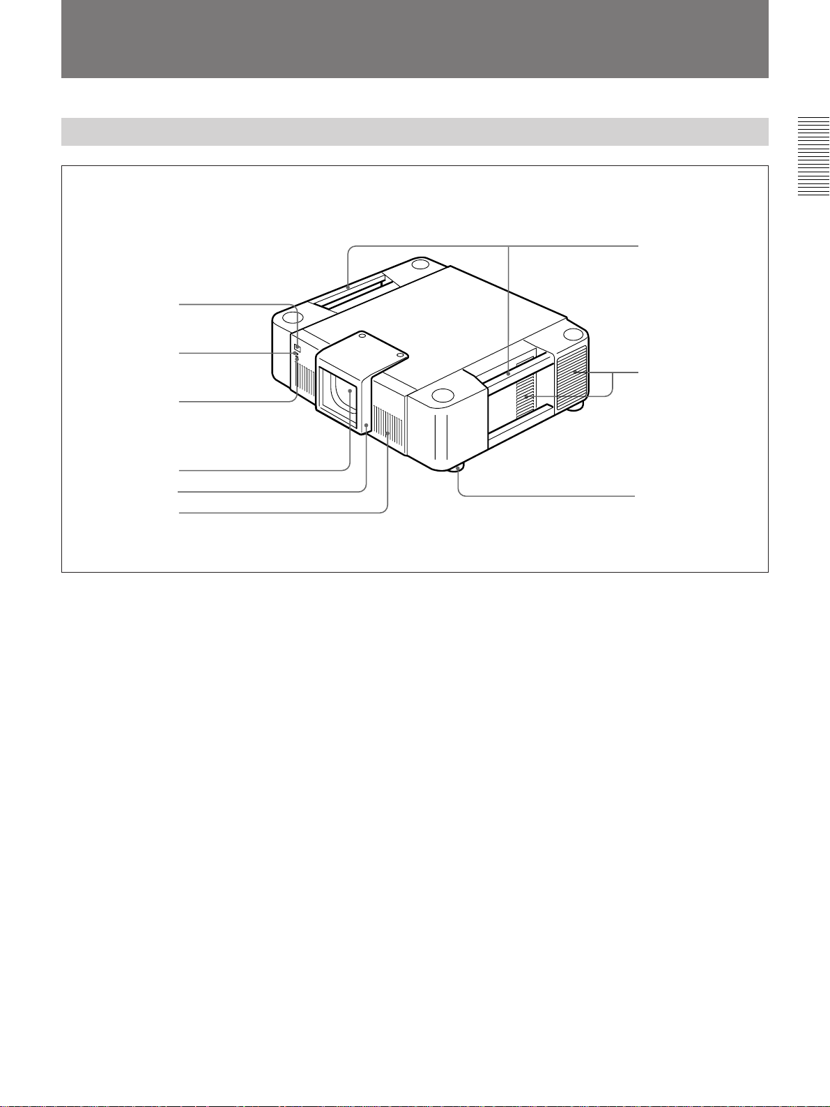
Front
1
2
3
Overview
7
8
4
5
6
1 Front remote control detector
2 POWER ON lamp
3 STANDBY lamp
4 Lens mount
Attach the projection lens.
5 Lens cover
6 Ventilation holes (intake)
7 Side handles
Used to carry the projector.
9
8 Ventilation holes (intake)
There are also ventilation holes on the opposite side.
9 Adjusters
Used to keep the projector level if it is installed on an
uneven surface.
7 (EN)
Page 8
Location and Function of Controls
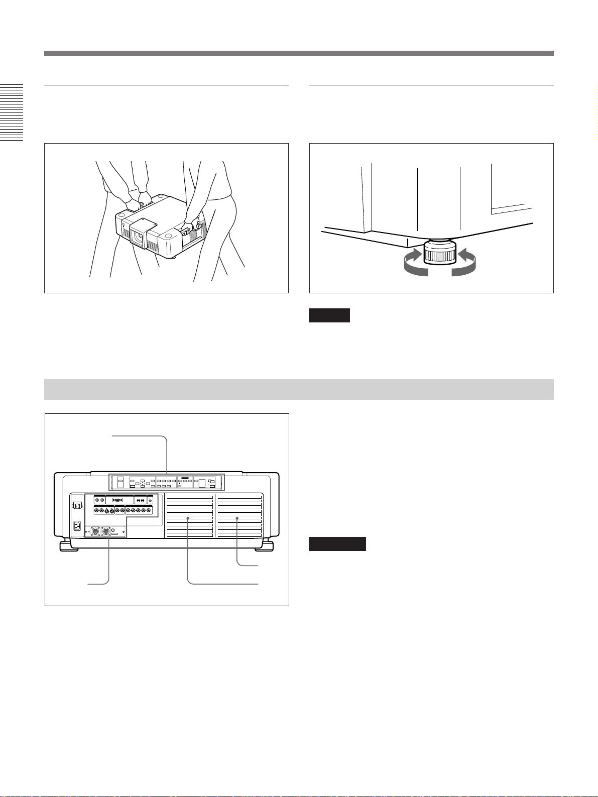
To carry the projector
Use the side handles as illustrated below.
Overview
To use the adjusters
Turn the screw to adjust the height so that the projector
becomes level.
To raise
the projector
Note
Be careful not to let the projector down on your
fingers.
To lower
the projector
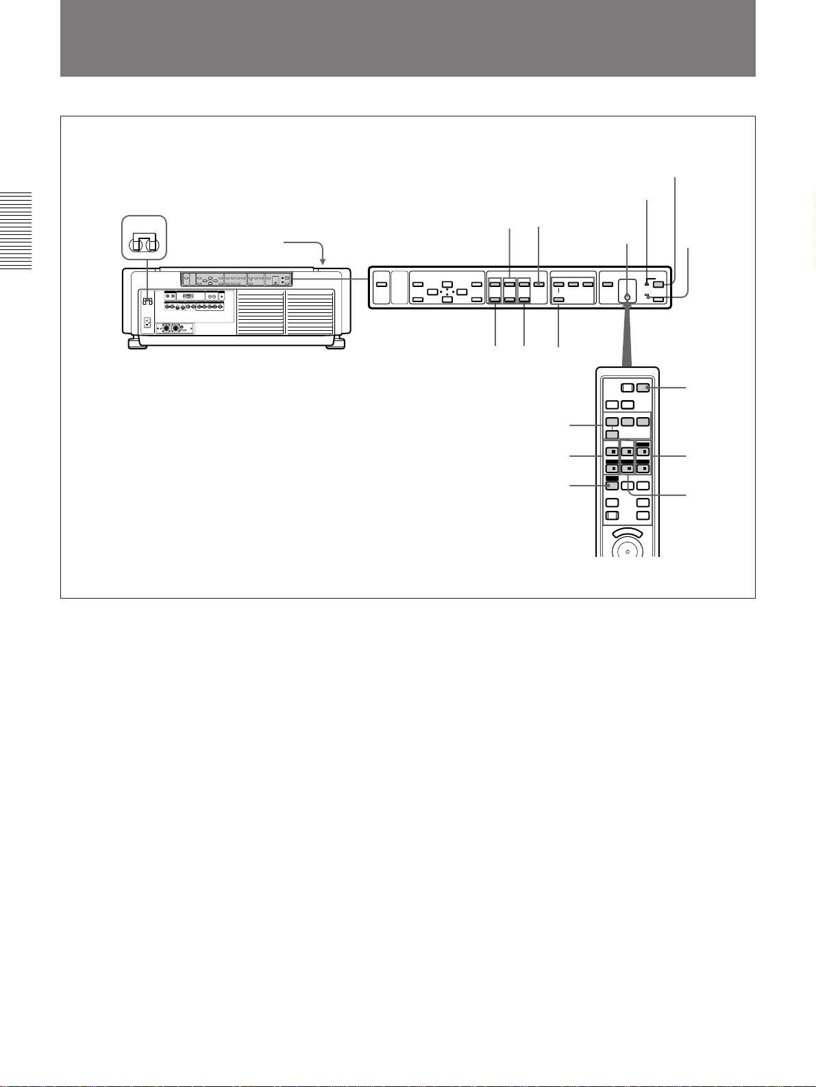
Rear
BREAKER ON/OFF
ON ON
AC IN
4
1
CONTROL S
IN
OUT
PLUG IN
POWER
S VIDEO VIDEO INPUT A
Y IN C IN IN OUT IN OUT
REMOTE 1
IN
MODE
OUT
MUTING
PICTURE
REMOTE
RS-422A
MEMORY
RESET
INDEX
0 0
R/R-Y G/Y B/B-YSYNC/HD VD
MENU SHIFT PATTERNZOOM FOCUS
ENTER
TRIG
1 Control panel
For details, see page 9.
2 Lamp cover
LENS CONTROL
INPUT SELECT
POWER
BAVIDEO
LIGHT
+–+–+
–
SELECT
VIDEO/S VIDEO
ON
STANDBY u
OFF
g
3 Ventilation holes (exhaust)
4 Input/output connectors
For details, see page 11.
Caution
2
3
Do not block the ventilation holes (both intake and
exhaust). Otherwise, internal heat may build up,
causing fire or damage to the projector.
8 (EN)
Page 9
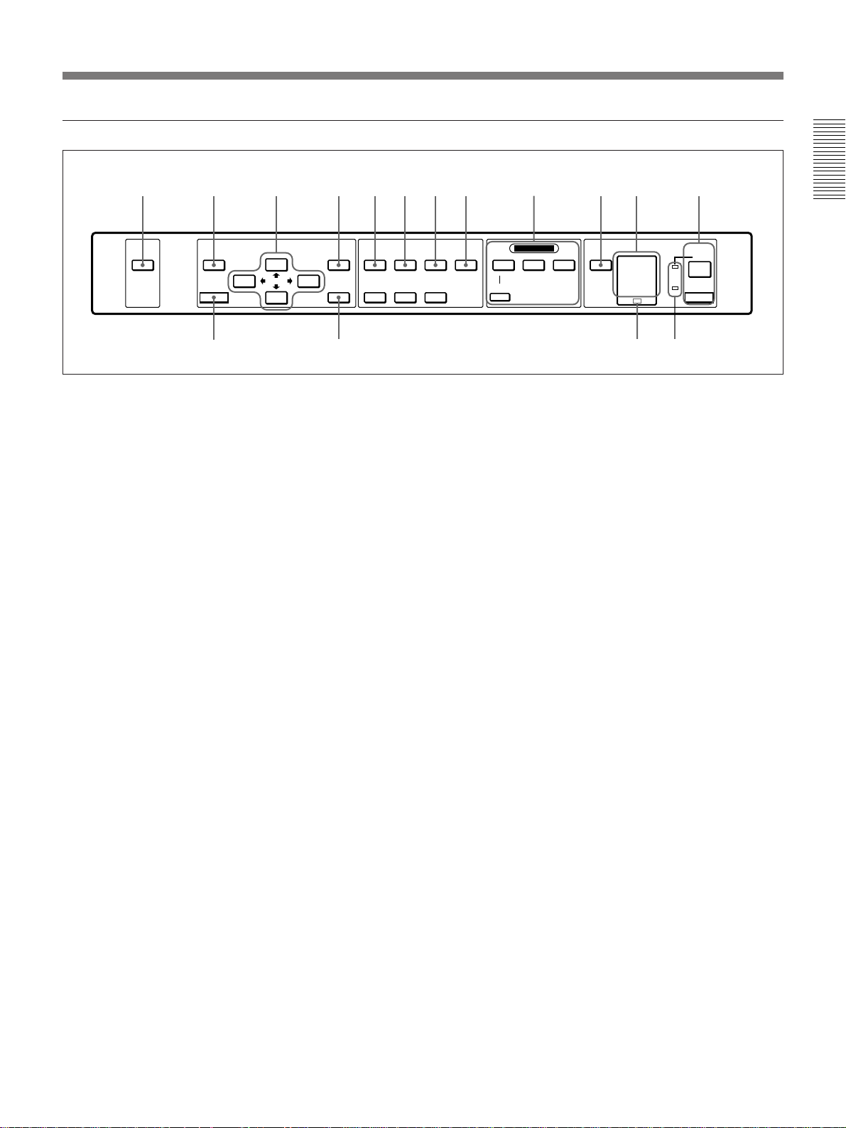
Control panel
31 2 4 5678 0
MUTING
PICTURE
MEMORY
RESET
!⁄
MENU SHIFT PATTERNZOOM FOCUS
+
–
ENTER
!
1 MUTING PICTURE key
Cuts off the picture. The screen turns in black. Press
again to restore the picture.
2 MEMORY key
Stores various adjustment data in the INPUT
SETTING menu into memory.
3 Arrow keys (V/v/B /b)
Used to select the menu or to make various
adjustments.
9
LENS CONTROL
+
+
–
–
SELECT
INPUT SELECT
VIDEO/S VIDEO
9 INPUT SELECT keys
Select the input video signal.
VIDEO: Selects the signal input from the VIDEO or
S VIDEO connectors. To switch the signal, use
the SELECT key.
SELECT: Switches the signal input from the VIDEO
or S VIDEO connectors.
INPUT A: Selects the signal input from the INPUT
A connectors.
INPUT B: Selects the signal input from the INPUT B
section when the optional interface board other
than the IFB-40 is installed.
!` !“
Overview
STANDBY u
!£
POWER
ON
OFF
BAVIDEO
LIGHT
g
!¢
4 MENU key
Displays the on-screen menu. Press again to clear the
menu.
5 SHIFT +/– keys
Adjust the vertical position of the picture.
+ : Picture moves upward.
– : Picture moves downward.
6 ZOOM +/– keys
Adjust the picture size.
+ : Picture size is enlarged.
– : Picture size is reduced.
7 FOCUS +/– keys
Adjust the focus.
+ : Picture focuses forward.
– : Picture focuses farther back.
8 PATTERN key
Displays the test pattern on the screen for focus, zoom
and shift adjustments. Press again to clear the test
pattern.
!… LIGHT key
Turns on the back lighting for the keys on the control
panel when the power is turned on. Press again to turn
off the back lighting. If you do not press any key for
30 seconds, the back lighting turns off automatically.
!` Error code display window
Displays the error codes.
For details on the error codes, see “Error codes” on page
50.
!“ POWER ON/OFF keys
ON : Turns on the projector when the projector is in
standby mode. The POWER indicator lights in
green when the power is turned on.
OFF : Sets the projector to standby mode.
(Continued)
9 (EN)
Page 10

Location and Function of Controls
!£ Indicators
POWER: Lights in green when the power is turned
on.
Flashes in green while the cooling fan runs after
Overview
turning off the power with the POWER OFF key.
The fan runs for about 15 minutes after turning off
the power.
STANDBY: Lights in red when the BREAKER ON/
OFF switch on the rear panel is turned on.
Once in standby mode, you can turn the projector
on and off with the POWER ON/OFF keys on the
control panel or the Remote Commander.
!¢ Rear remote control detector
! ENTER key
Enters the settings of items in the menu.
!⁄ RESET key
Resets the value of an item to its factory preset value.
This key functions when the menu or a setting item is
displayed on the screen.
10 (EN)
Page 11
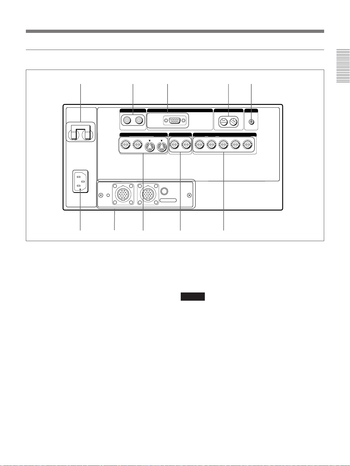
Input/output connectors
123 45
CONTROL S
BREAKER ON/OFF
ON ON
AC IN
REMOTE 1
IN
06
98 7
OUTIN
PLUG IN
POWER
S VIDEO VIDEO INPUT A
Y IN C IN IN OUT IN OUT
MODE
OUT
1 BREAKER ON/OFF switch
Turns the main power on and off.
2 CONTROL S IN/OUT (control S signal input/
output) jacks (stereo minijack)
Connect to the CONTROL S connectors of other Sony
equipment.
CONTROL S IN/PLUG IN POWER (5 V output)
jack: Connects to the CONTROL S OUT jack on
the supplied Remote Commander with the
supplied Remote Commander cable when using it
as a wired Remote Commander. The power for the
Remote Commander is supplied via this jack.
CONTROL S OUT jack: Outputs the control S
signal.
3 REMOTE RS-422A connector (D-sub 9-pin,
female)
Connects to a computer to control the projector.
REMOTE
RS-422A
INDEX
0
R/R-Y G/Y B/B-Y SYNC/HD VD
TRIG
1
4 INDEX (index number) switches
Set the index number for each projector when using
multiple projectors. You can set the numbers between
01 to 99.
You can check the index number using the menu.
Note
Do not use the index number “9” when using the
supplied Remote Commander.
5 TRIG (trigger output) jack (minijack)
Transmits approximately 5 V trigger signal to external
equipment when the power is on. This is not a power
source.
6 INPUT A connectors
Input the video signals of a component VCR or a
computer.
RGB input connectors (R-R/Y, G/Y, B/B-Y,
SYNC/HD, VD) (BNC-type): Connect to the
monitor output connectors on a component VCR
or a computer.
Overview
(Continued)
11 (EN)
Page 12
Location and Function of Controls
7 VIDEO connectors (BNC-type)
Connect to external video equipment such as a VCR.
You can use the VIDEO IN connector for bridge
connection.
Overview
IN: Connects to the video output connector of
external video equipment.
OUT: Connects to the video input connector of
external video equipment.
8 S VIDEO connectors
Connect to external video equipment such as a VCR.
You can use the Y IN/C IN connectors or IN connector
for bridge connection.
Y IN/C IN (BNC-type): Connect to the video output
connector of external video equipment.
IN (mini DIN 4-pin): Connects to the Y/C video
output connector of external video equipment.
OUT (mini DIN 4-pin): Outputs the video signal
input through the Y IN/C IN connectors or IN
connector.
Note
If you connect external video equipment to both the Y
IN/C IN connectors and IN connector, the signal from
the Y IN/C IN connectors is selected. In this case,
75-ohm termination is impossible. When projecting the
video signal from the IN connector, do not connect a
signal to the Y IN/C IN connectors.
9 Signal interface board attachment part (INPUT
B)
The IFB-40 Signal Interface Board is installed at the
factory. Other optional signal interface boards can be
inserted to this section instead of the IFB-40.
Indicator (red): Lights up when the input of the
IFB-40 is selected.
REMOTE 1 IN connector (14-pin multi):
Connect to the PC-1271/1271M Signal Interface
Switcher. When connecting two projectors,
connect to the REMOTE 1 OUT connector on the
IFB-40 installed in another projector.
REMOTE 1 OUT connector (14-pin multi):
Connect to the REMOTE 1 IN connector on the
IFB-40.
MODE selector: Turn the control switch of the
MODE selector to the appropriate position
according to the length of the cable connected to
the REMOTE 1 OUT connector.
Cable length
Cable type
Position
SIC-M-1
CCQ-2BRS
1
up to 10 mup to 2 m
SIC-M-5
CCQ-5BRS
CCQ-10BRS
2
SIC-M-15
CCQ-25BRS
SIC-M-25
up to 50 mup to 25 m
SIC-M-50
CCQ-50BRS
43
!… AC IN socket
Connects the supplied AC power cord.
This socket accepts 120 V AC power (for the VPDS1800Q) or 220 to 240 V AC (for the VPDS1800QM).
12 (EN)
Page 13
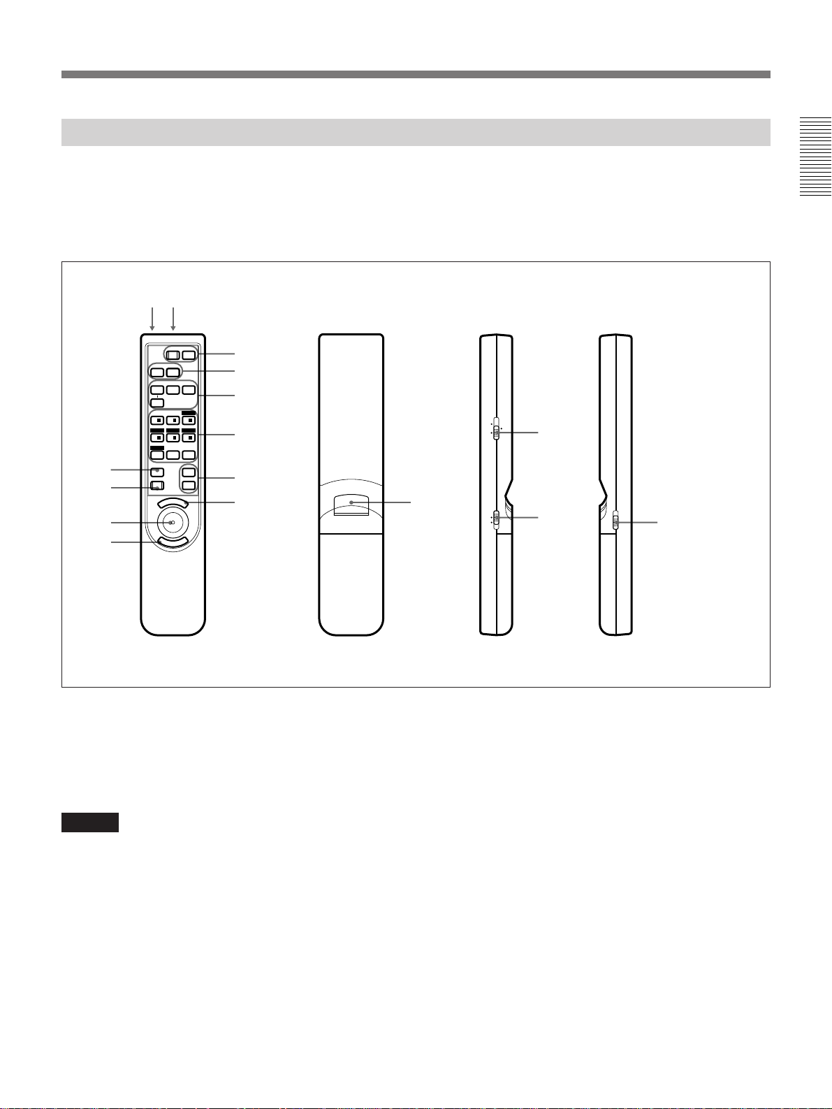
Remote Commander
The Remote Commander can be used as a wireless or
wired Remote Commander.
The keys which have the same names as on the control
panel function identically.
!“ !£
POWER
OFF
!`
!…
MUTING
AUDIO
INPUT SELECT
SELECT
VIDEO/S VIDEO
SWITCHER
+
1/
ZOOMSHIFT
4/ – 5/ – 6/
PATTERN
MEMORY
RESET
M
PIC
AVIDEO
2/ + 3/
87 ALL
N
U
E
/ LENS /INDEX
FOCUS
SECOND
VOLUME
ON
B
+
–
+
–
1
2
3
5
6
7
9
E
R
N
E
8
T
When you use the RM-PJ21 Mouse Receiver (not
supplied), you can control the connected computer
using the Remote Commander.
For details, refer to the instruction manual of the RM-PJ21
Mouse Receiver.
INDEX
LENS SWITCHER
8
MOUSE MENU
4
!¢
LIGHT
!
Overview
Front Rear
1 POWER ON/OFF keys
2 MUTING PIC/AUDIO key
Functions in the same way as the MUTING PICTURE
key on the control panel.
Note
The MUTING AUDIO key does not function with this
unit.
3 INPUT SELECT keys
4 SWITCHER/INDEX/LENS switch
Switches the function of the SWITCHER/INDEX/
LENS keys.
SWITCHER: Designates the input from the signal
interface switcher (not supplied).
INDEX: Selects the index number for each projector
when multiple projectors are connected.
LENS: Adjusts the focus, zoom and shift.
Side (right)
Side (left)
5 SWITCHER/INDEX/LENS keys
Function as described below by switching the position
of the SWITCHER/INDEX/LENS switch.
When the SWITCHER/INDEX/LENS switch is
set to SWITCHER
The SWITCHER/INDEX/LENS keys designate the
input when the signal interface switcher (not supplied)
is connected to the projector.
The SECOND key is used when two switchers are
connected to the projector. To select the input from the
second switcher (when the SINGLE/SECOND/
OTHER switch on the switcher is set to SECOND),
press the SECOND key, and then a number key
between 1 and 8.
(Continued)
13 (EN)
Page 14
Location and Function of Controls
+
FOCUSZOOMSHIFT
PATTERN
++
–
––
Overview
1
4
Designate the input from the switcher.
23
56
SECOND
87
When the SWITCHER/INDEX/LENS switch is
set to INDEX
The SWITCHER/INDEX/LENS keys are used to
select the index number preset for each projector when
multiple projectors are connected. Press the index
number and ENTER key.
When you select the index number using the Remote
Commander, “INDEX: xx” is displayed on the screen.
(“xx” is the index number of the projector.) On the
screen of the projector that is currently selected, the
index number is displayed in green. The index
numbers for other projectors are displayed in yellow.
This color designation shows you which projector is
currently selected.
Adjusts the shift.
Adjusts the zoom.
Adjusts the focus.
Displays or clears the test pattern.
6 VOLUME +/– keys
These keys do not function with this unit.
7 MENU key
8 ENTER key
9 Joy stick
Used to select the menu or to make various
adjustments.
!… RESET key
1 23
4
Select the index number for each projector.
56
87 ALL
When the SWITCHER/INDEX/LENS switch is
set to LENS
The SWITCHER/INDEX/LENS keys are used for
focus, zoom and shift adjustments and for displaying
or clearing the test pattern on the screen.
!` MEMORY key
!“ CONTROL S OUT (control S signal output)
jack (stereo minijack)
Connects to the CONTROL S IN jack on the projector
when using the Remote Commander as a wired
Remote Commander. In this case, you do not need to
install the batteries in the Remote Commander since
the power is supplied from the CONTROL S IN/PLUG
IN POWER jack on the projector.
!£ Infrared transmitter
!¢ MOUSE/MENU switch
Normally set to MENU.
Set to MOUSE when controlling a computer connected
to the RM-PJ21 Mouse Receiver from the Remote
Commander.
When the MOUSE/MENU switch is set to MOUSE,
the MENU key, ENTER key and joy stick function as
listed on the next page.
14 (EN)
Page 15
Key Function
IBM1) PC/AT
2)
Macintosh
3)
compatible
MENU Left click ENTER/click
ENTER (front) Right click ENTER/click
ENTER (rear) Right click ENTER/click
Joy stick Corresponds to the movement of the
mouse
! LIGHT switch
Turns on the back lighting for the keys on the Remote
Commander. Press again to turn off the back lighting.
If you do not press any key for 30 seconds, the back
lighting turns off automatically.
Notes on wireless Remote Commander
operation
• Make sure that there is nothing to obstruct the
infrared beam between the Remote Commander and
the remote control detector on the projector.
• The operation range is limited. The shorter the
distance between the Remote Commander and the
projector is, the wider the angle within which the
commander can control the projector.
• The remote control detectors on the projector do not
operate when the Remote Commander is being used
as a wired Remote Commander. When using the
Remote Commander as a wireless Remote
Commander, remove the Remote Commander cable
from both the Remote Commander and the projector.
Overview
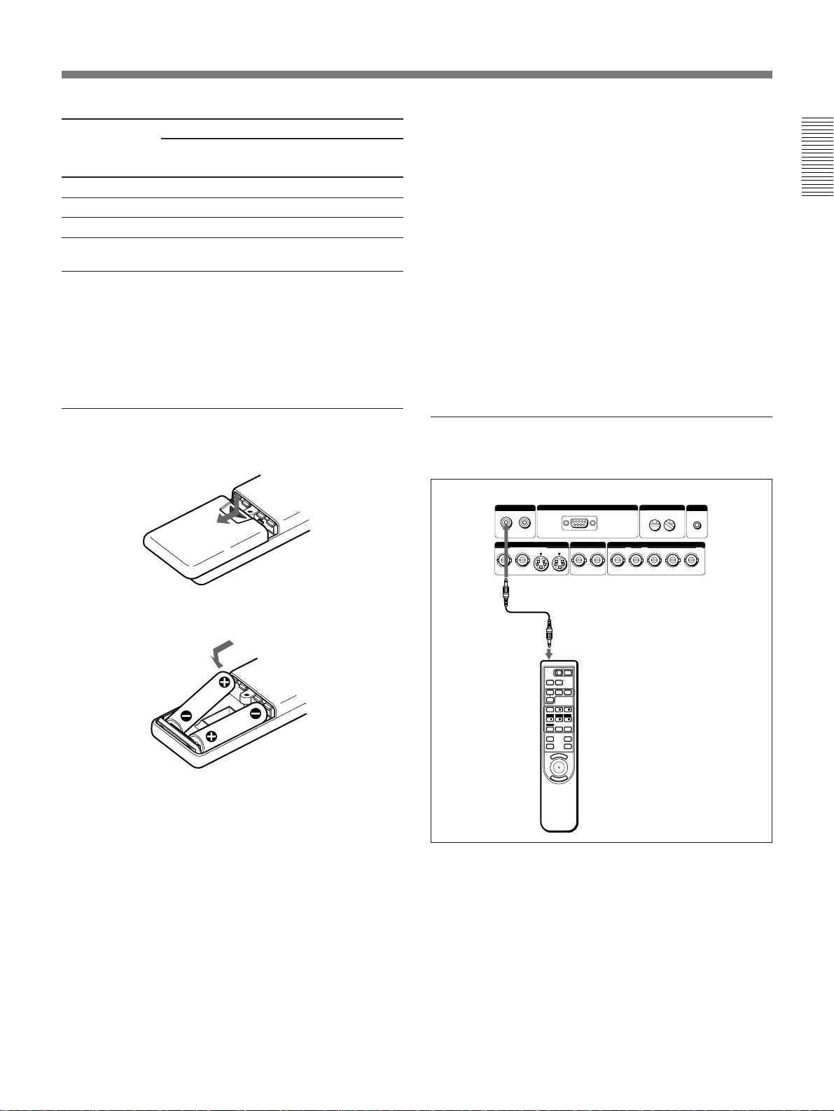
Battery installation
1 Push and slide to open the lid.
2 Install the two size AA (R6) batteries (supplied)
with the correct polarity.
Install the battery
from the end.
3 Replace the lid.
Notes on batteries
• Make sure that the battery orientation is correct when
inserting batteries.
• Do not mix an old battery with a new one, or
different types of batteries.
• If you will not use the Remote Commander for a long
time, remove the batteries to avoid damage from
battery leakage. If batteries have leaked, remove
them, wipe the battery compartment dry and replace
the batteries with new ones.
To connect the Remote Commander to the
projector
Rear
CONTROL S
IN
OUT
PLUG IN
POWER
S VIDEO VIDEO INPUT A
Y IN C IN IN OUT IN OUT
REMOTE
RS-422A
R/R-Y G/Y B/B-Y SYNC/HD VD
Remote Commander
cable (supplied)
POWER
OFF
ON
MUTING
PIC
AUDIO
INPUT SELECT
AVIDEO
B
SELECT
VIDEO/S VIDEO
/ LENS /INDEX
SWITCHER
+
+
1/
2/ + 3/
FOCUS
ZOOMSHIFT
–
4/ – 5/ – 6/
SECOND
PATTERN
87 ALL
MEMORY
+
VOLUME
RESET
–
N
E
U
M
E
R
N
E
T
Note on wired Remote Commander operation
You do not need to install the batteries since the power
is supplied from the CONTROL S IN jack on the
projector. Even if batteries are installed in the Remote
Commander, they are not used.
INDEX
0
TRIG
1
..........................................................................................................................................................................................................
1) IBM is a trademark of International Business Machines Corporation, U.S.A.
2) IBM PC/AT is a trademark of International Business Machines Corporation, U.S.A.
3) Macintosh is a trademark of Apple Computer Inc.
15 (EN)
Page 16
Projecting the Picture on the Screen
2
POWER indicator
Projecting
1
BREAKER ON/OFF
ON ON
BREAKER ON/OFF
ON ON
AC IN
Front remote control
detector
REMOTE
RS-422A
OUT
S VIDEO VIDEO INPUT A
R/R-Y G/Y B/B-YSYNC/HD VD
MODE
OUT
INDEX
TRIG
0 0
CONTROL S
PLUG IN
POWER
Y IN C IN IN OUT IN OUT
REMOTE 1
IN
IN
MUTING
PICTURE MEMORY
RESET
MENU
ENTER
64
LENS CONTROL
ZOOM
SHIFT
+
+
–
–
Rear remote
control detector
INPUT SELECT
PATTERNFOCUS
VIDEO
+
–
SELECT
VIDEO/S VIDEO
LIGHTB
A
STANDBY u
g
POWER
ON
OFF
STANDBY
indicator
357
POWER
OFF
3
7
4
AUDIO
VIDEO
SELECT
SWITCHER
1/
4/
PATTERN
MEMORY
RESET
MUTING
PIC
INPUT SELECT
VIDEO/S VIDEO
+
2/ + 3/
ZOOMSHIFT
–
5/ – 6/
7
E
M
A
/ LENS /INDEX
8 ALL
VOLUME
N
U
FOCUS
SECOND
ON
B
+
–
+
–
2
5
6
1 Set the BREAKER ON/OFF switch on the rear panel to ON.
The STANDBY indicator lights in red and the projector goes into the
standby mode.
2 Press the POWER ON key on the Remote Commander or the control
panel.
The POWER indicator lights in green.
3 Turn on the equipment connected to the projector, and then press the
INPUT SELECT keys on the Remote Commander or the control panel
to select the input source.
VIDEO: Selects the video signal input from the VIDEO or S
VIDEO connectors. To switch the video signal, use the
SELECT key.
SELECT: Switches the video signal input from the VIDEO or S
VIDEO connectors.
INPUT A: Selects the video signal input from the INPUT A
connectors.
INPUT B: Selects the signal input from the INPUT B section when
the optional interface board other than the IFB-40 is
installed.
16 (EN)
Page 17
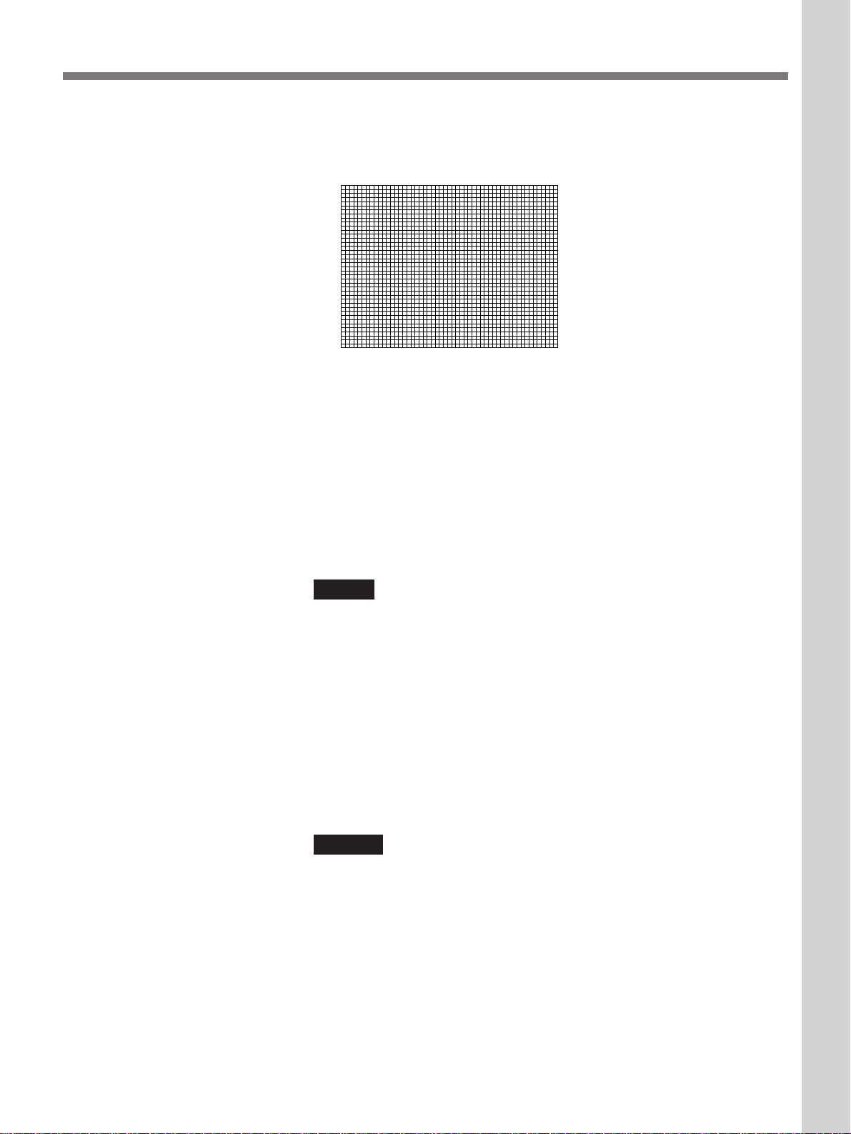
4 Press the PATTERN key on the Remote Commander or the control
panel to display the test pattern.
To clear the test pattern, press the PATTERN key again.
5 Press the FOCUS +/– keys on the Remote Commander or the control
panel to adjust the focus.
“FOCUS” appears on the screen during adjustment.
Projecting
Projecting
6 Press the ZOOM +/– keys on the Remote Commander or the control
panel to adjust the zoom.
“ZOOM” appears on the screen during adjustment.
Note
When the VPDL-FP30 fixed short focus lens is attached to the projector,
you cannot use the zoom function.
7 Press the SHIFT +/– keys on the Remote Commander or the control
panel to adjust the vertical position of the picture.
“PICTURE SHIFT” appears on the screen during adjustment.
To cut off the picture
Press the MUTING PICTURE key on the control panel or the MUTING
PIC key on the Remote Commander. To restore the picture, press the
MUTING PICTURE or MUTING PIC key again.
Notes
• The operating temperature guaranteed for the projector is 10°C to 35°C
(50°F to 95°F). When the temperature around the projector is out of the
operating temperature range, no picture may appear on the screen even if
you turn the power on. (75 or 27 lights up in the error code display
window.) In this case, adjust the temperature around the projector.
When the temperature sensor for the lamp power or the lamp housing
functions, the lamp may turn off. (23 or 24 lights up in the error code
display window.)
For details on the error codes, see “Error codes” on page 50.
• Do not look into the lens when the projector lamp is on.
• When you adjust the focus, zoom and shift using the Remote
Commander, set the SWITCHER/INDEX/LENS switch to LENS.
17 (EN)
Page 18

Projecting the Picture on the Screen
To turn off the power
1 Press the POWER OFF key on the Remote Commander or the control
panel.
The fan continues to run for about 15 minutes to reduce the internal
heat. The POWER indicator flashes in green.
Projecting
2 Make sure that the fan has stopped running and the STANDBY
indicator lights in red, and then set the BREAKER ON/OFF switch to
OFF.
Note
Do not turn off the power with the BREAKER ON/OFF switch while the
fan is still running. Otherwise, internal heat may not be dissipated, causing
damage to the projector.
18 (EN)
Page 19
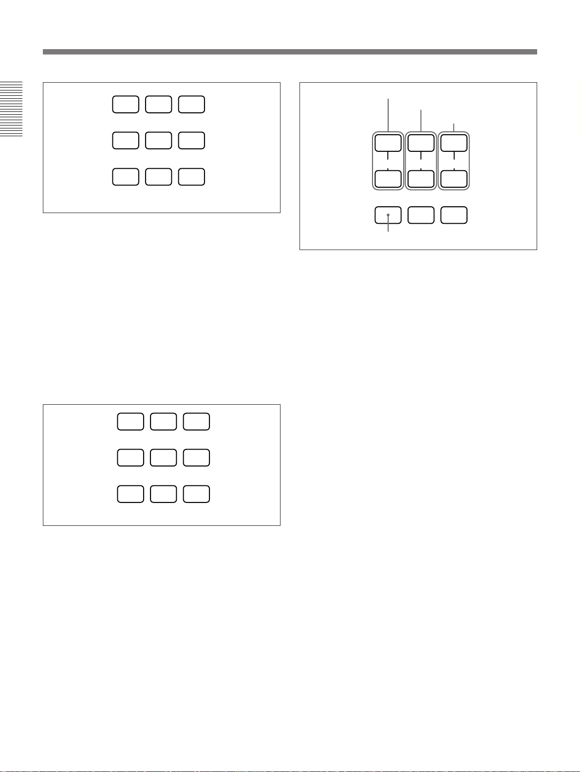
Using the Menu
Adjustments and Settings Using the Menu
The projector is equipped with an on-screen menu for
making various adjustments and settings.
To select the language used in the menu, see page
28.
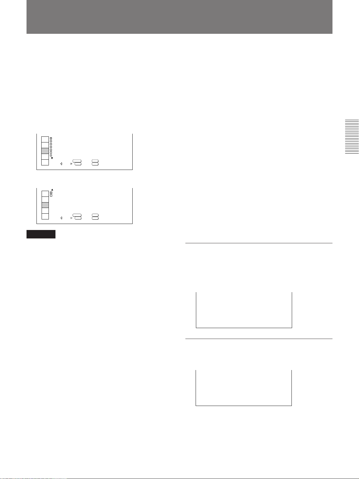
Basic operation
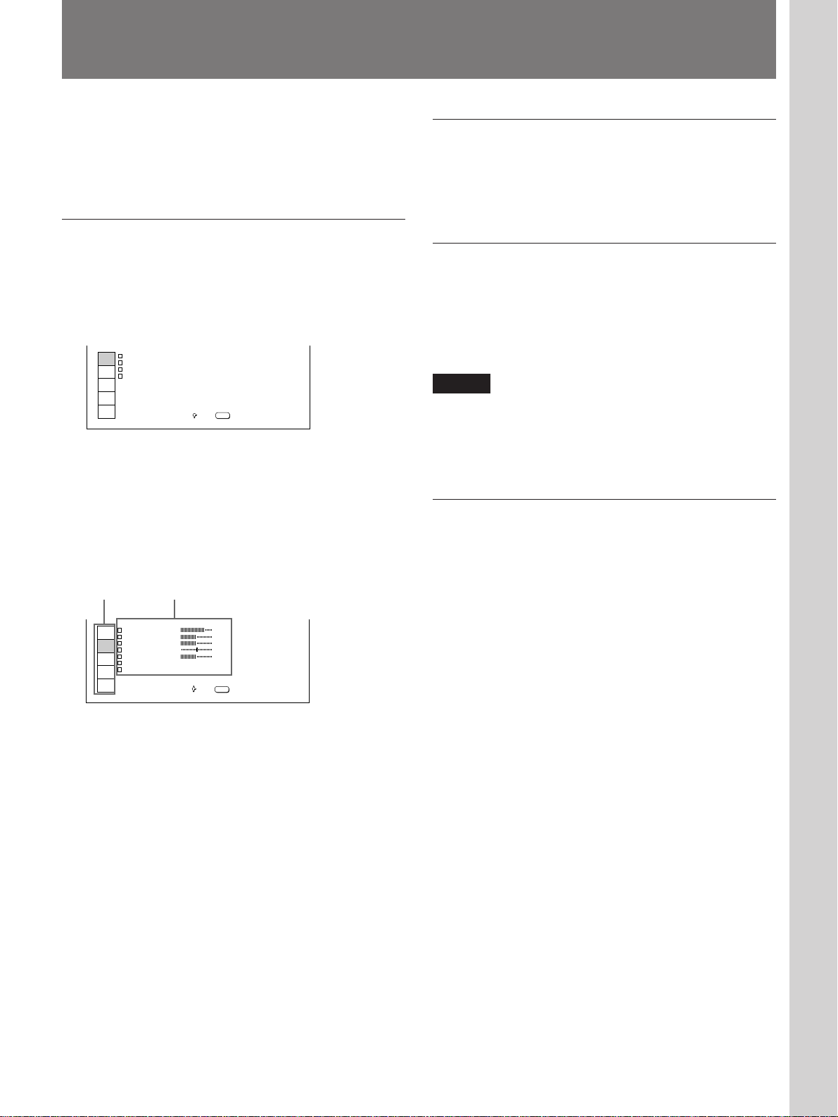
1 Press the MENU key.
The menu display appears.
The menu presently selected is highlighted in blue.
INPUT
SELECT
PICTURE
CTRL
INPUT
SETTING
SET
SETTING
INPUT
INFO
NPUT SELECTI
V DEOI
V DEOI:
I NPUT- A
I NPUT- B
SW TCHER
SW ER - 1
I:
SEL: EXIT:
'1
MENU
2 Select a menu using the V or v key on the control
panel, then press the b or ENTER key.
On the Remote Commander, move the joy stick up
or down to select a menu, then move it to the right
or press the ENTER key.
Now you can select the item in the menu.
Menus Items
P CTURE CTRL I
INPUT
CONTRAST
SELECT
BR GHTI
PICTURE
COLOR
CTRL
HUE
INPUT
SHARP
SETTING
COLOR SYS :AUTO
SET
S GI TYPE :NORMAL
SETTING
INPUT
INFO
SEL: EXIT:
80
50
50
50
50
MENU
To clear the menu display
Press the MENU key.
The menu display disappears automatically if no key is
pressed for approximately one minute.
To reset the setting
Press the RESET key.
The message “RESET complete!” appears on the
screen, and the setting displayed on the screen is reset
to its factory preset setting.
Adjustments and Settings Using the Menu
Note
When you press the RESET key for the items that
cannot be reset, the message “Not applicable!” appears
on the screen. The settings are not reset to their factory
preset settings.
Memory of the settings
The settings other than in the INPUT SETTING menu
are automatically stored in memory. For the settings in
the INPUT SETTING menu, press the MEMORY key
on either the control panel or the supplied Remote
Commander.
3 Make adjustment or setting on the selected item.
For details, see the relevant menu pages.
19 (EN)
Page 20
The INPUT SELECT Menu
The INPUT SELECT menu is used for selecting the
input signal.
Adjustable items are displayed in green.
INPUT
SELECT
PICTURE
CTRL
INPUT
SETTING
SET
SETTING
INPUT
INFO
NPUT SELECTI
V DEOI
V DEOI:
I NPUT- A
I NPUT- B
SW TCHER
SEL: EXIT:
SW ER - 1
SET:
/
'1
ENTER
I:
MENU
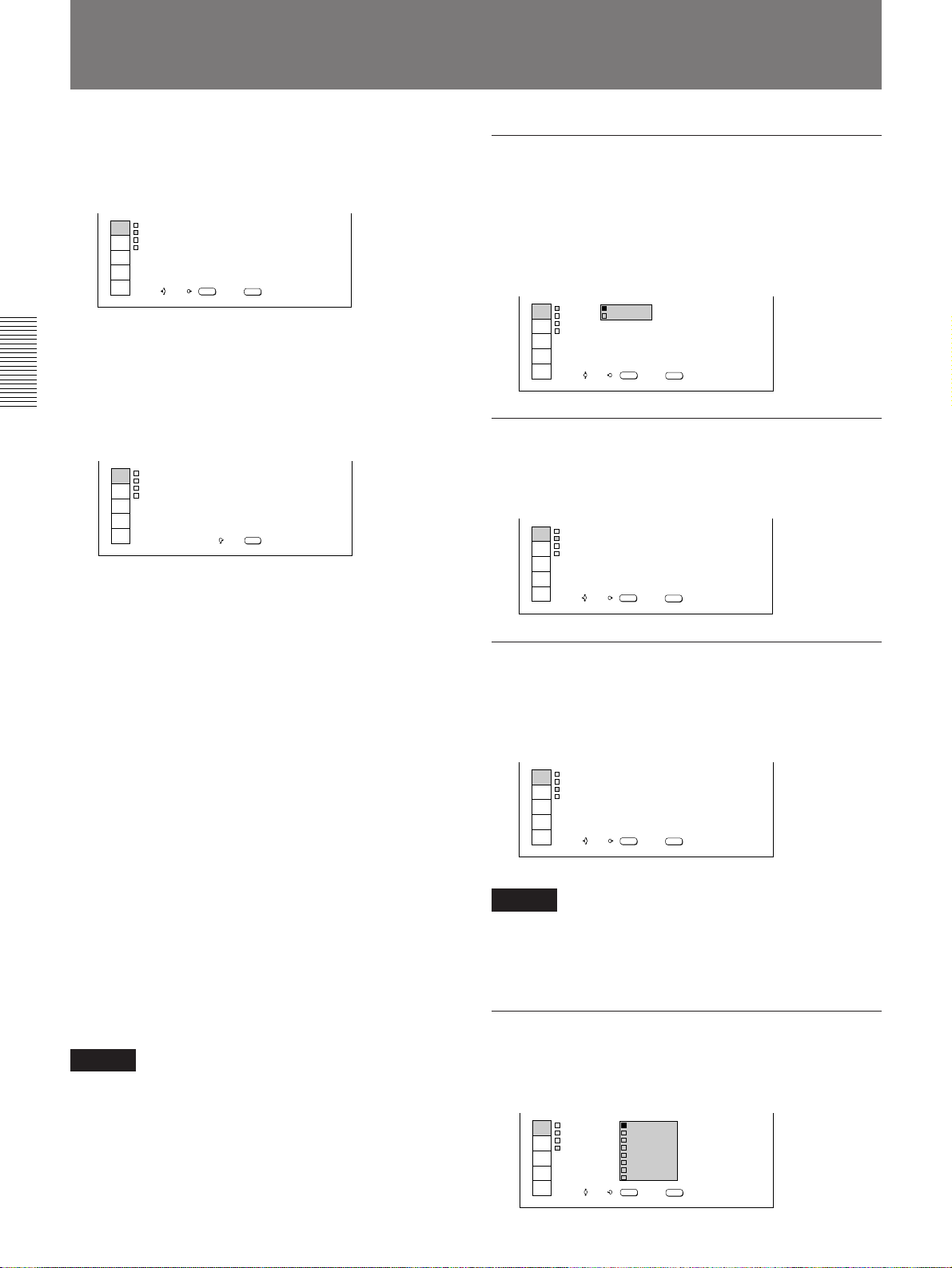
Operation
1 Press the MENU key.
Adjustments and Settings Using the Menu
The menu display appears.
The menu presently selected is highlighted in blue.
INPUT
SELECT
PICTURE
CTRL
INPUT
SETTING
SET
SETTING
INPUT
INFO
NPUT SELECTI
V DEOI:
V DEOI
I NPUT- A
I NPUT- B
SW TCHER
SW ER - 1
I:
SEL: EXIT:
'1
MENU
2 Select the INPUT SELECT menu using the V or v
key on the control panel, then press the b or
ENTER key.
On the Remote Commander, move the joy stick up
or down to select the INPUT SELECT menu, then
move it to the right or press the ENTER key.
Now you can select the item in the menu.
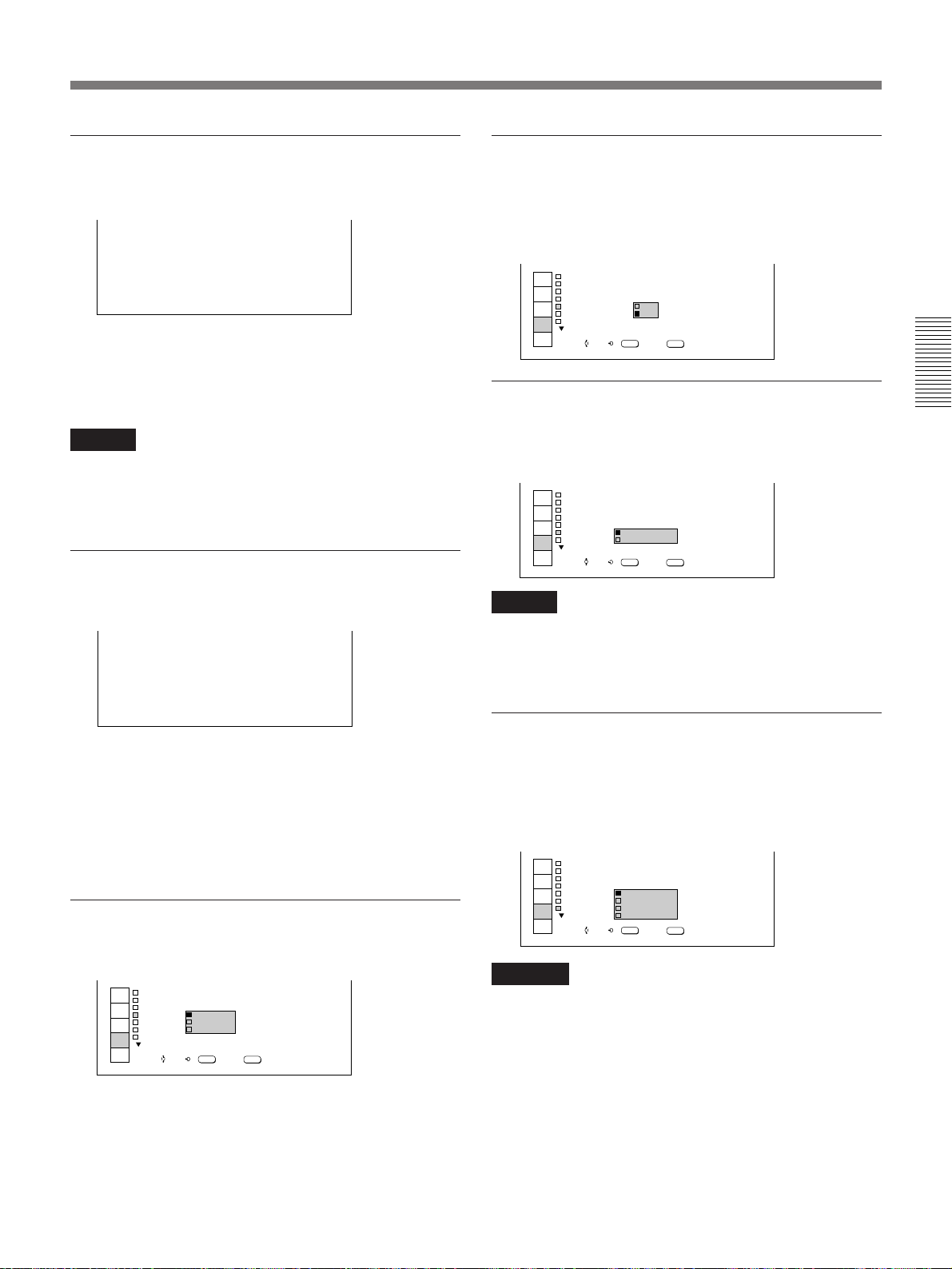
3 Select the input signal using the V or v key on the
control panel.
On the Remote Commander, move the joy stick up
or down to select the input signal.
When you select “VIDEO” or “SWITCHER,”
settings to be selected are displayed.
Select the input signal following the procedure
below.
Select the input signal using the V or v key on the
control panel, then press the B or ENTER key.
On the Remote Commander, move the joystick up
or down to select the input signal, then move it to
the left or press the ENTER key.
The previous screen is restored.
VIDEO
Selects the video signal input from the VIDEO or S
VIDEO connectors.
If you select S-VIDEO when you have connected video
equipment to both the Y IN/C IN and IN connectors, the
signal from the Y IN/C IN connectors is selected.
INPUT
SELECT
PICTURE
CTRL
INPUT
SETTING
SET
SETTING
INPUT
INFO
NPUT SELECTI
V DEOI
V DEOI:
I NPUT- S
I NPUT- B
SW TCHER
- V DEOI
SW ER - 1
SET:
/
'1
ENTER
I:
SEL: EXIT:
MENU
INPUT-A
Selects the video signal input from the INPUT A
connectors.
INPUT
SELECT
PICTURE
CTRL
INPUT
SETTING
SET
SETTING
INPUT
INFO
NPUT SELECTI
V DEOI
V DEOI:
I NPUT- A
I NPUT- B
SW TCHER
SEL: EXIT:
SW ER - 1
SET:
/
'1
ENTER
I:
MENU
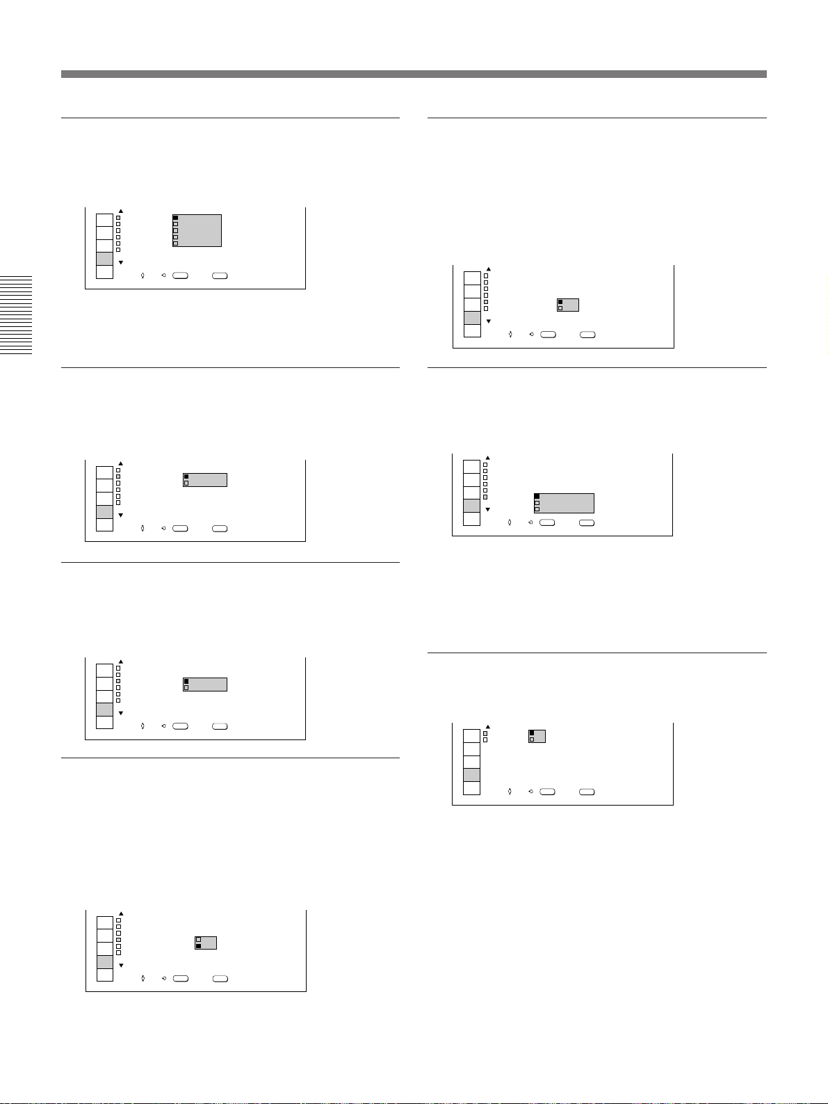
INPUT-B
Selects the signal input from the INPUT B section
when the optional interface board other than the IFB40 is installed.
INPUT
SELECT
PICTURE
CTRL
INPUT
SETTING
SET
SETTING
INPUT
INFO
NPUT SELECTI
V DEOI
V DEOI:
I NPUT- A
I NPUT- B
SW TCHER
SEL: EXIT:
SW ER - 1
SET:
/
'1
ENTER
I:
MENU
Note
When the IN/OUT switch on the IFB-12 Signal
Interface Board (not supplied) installed in the projector
is set to OUT, you cannot select this item.
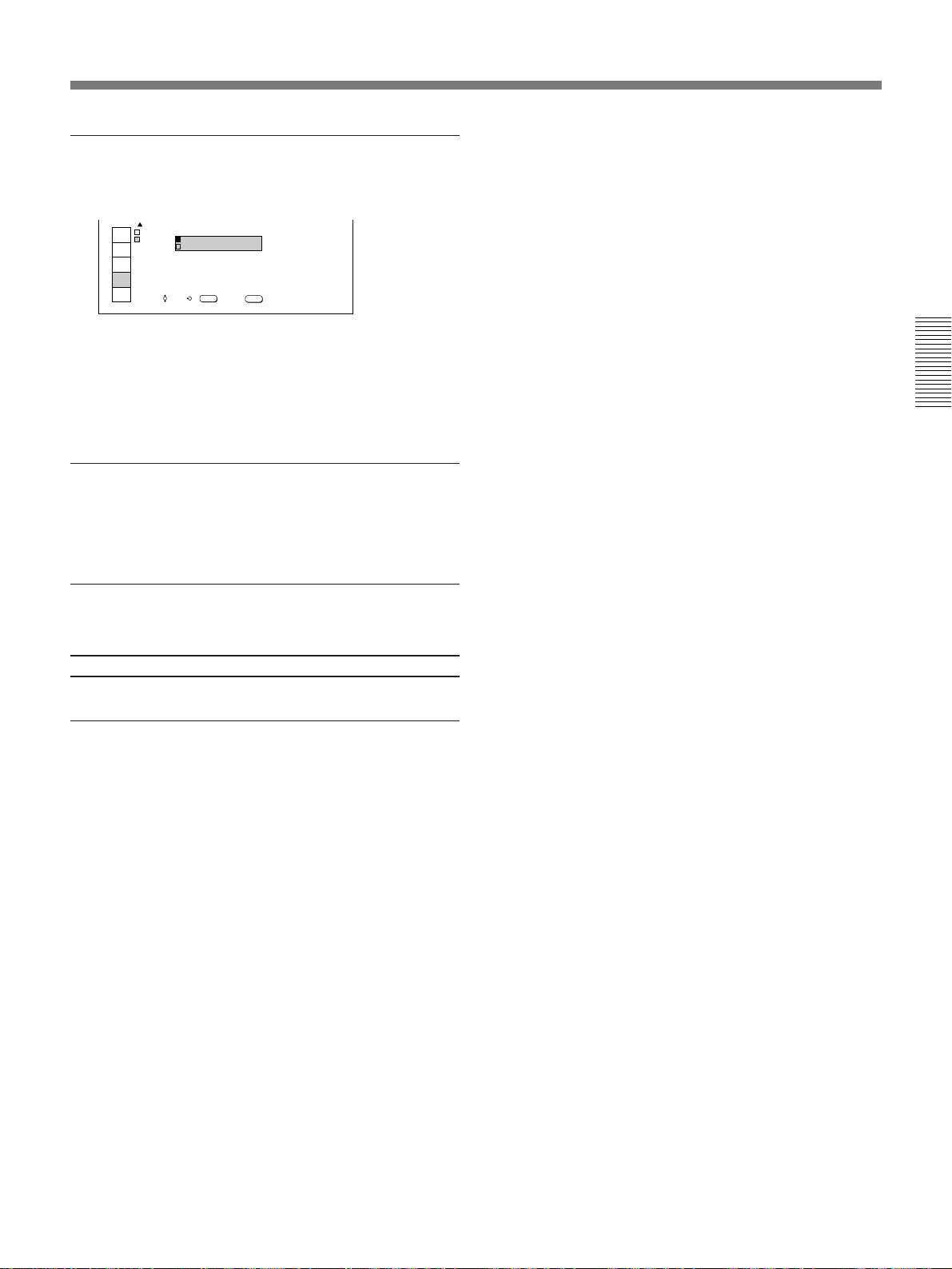
SWITCHER
Note
When you change the input signal, the picture size may
also change.
20 (EN)
Selects the input signal from the equipment connected
to the signal interface switcher (not supplied).
INPUT
SELECT
PICTURE
CTRL
INPUT
SETTING
SET
SETTING
INPUT
INFO
NPUT SELECTI
V DEOI
I NPUT- A
I NPUT- B
SW TCHER
SW ER - 1'1
V DI
SW ER - 2'1
SW ER - 3'1
SW ER - 4'1
I:
SW ER - 5'1
SW ER - 6'1
SW ER - 7'1
SW ER - 8'1
ENTER
SET:SEL: EXIT:
/
MENU
Page 21
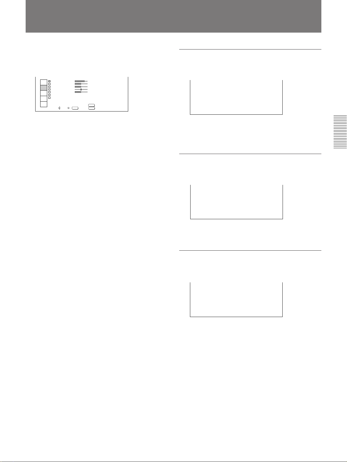
The PICTURE CTRL Menu
The PICTURE CTRL menu is used for adjusting the
picture.
Adjustable items are displayed in green.
P CTURE CTRL I
INPUT
CONTRAST
SELECT
BR GHTI
PICTURE
COLOR
CTRL
HUE
INPUT
SHARP
SETTING
COLOR SYS :AUTO
SET
S GI TYPE :NORMAL
SETTING
INPUT
INFO
SET:SEL: EXIT:
/
ENTER
RESET:
80
50
50
50
50
RESET
MENU
Operation
1 Press the MENU key.
The menu display appears.
The menu presently selected is highlighted in blue.
2 Select the PICTURE CTRL menu using the V or v
key on the control panel, then press the b or
ENTER key.
On the Remote Commander, move the joy stick up
or down to select the PICTURE CTRL menu, then
move it to the right or press the ENTER key.
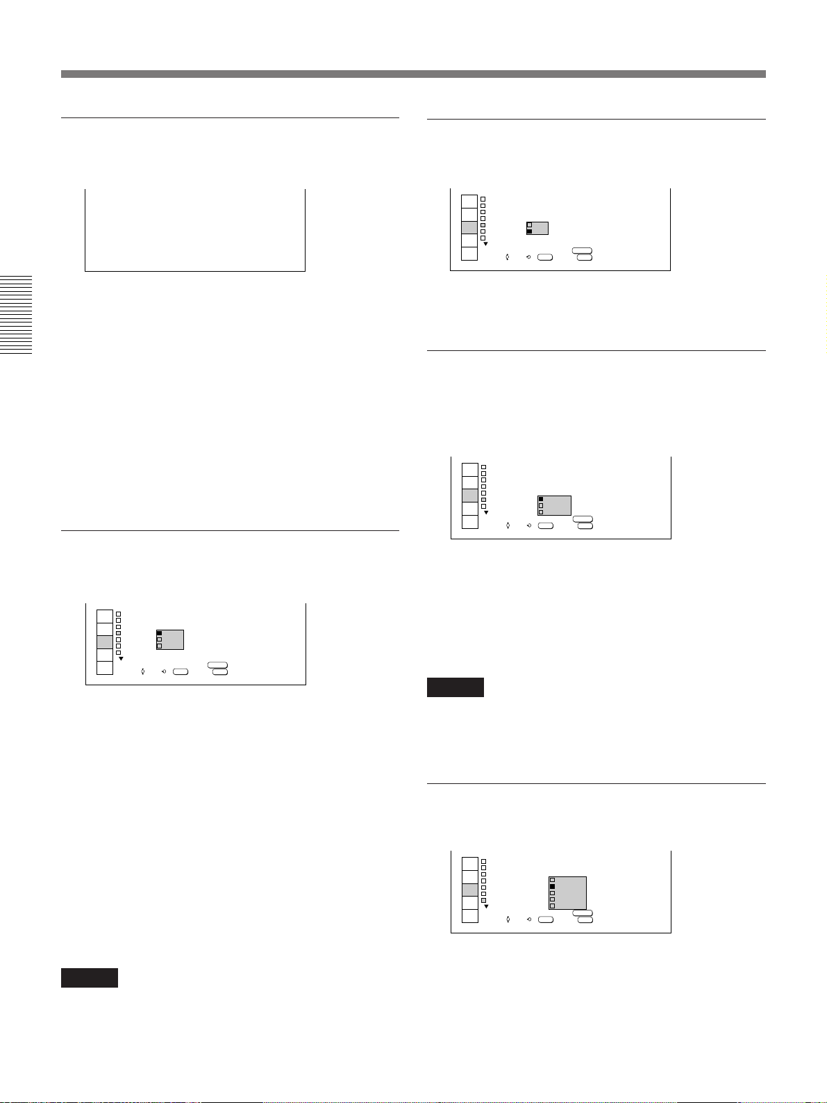
CONTRAST
Adjusts the picture contrast.
CONTRAST :80
The higher the setting level is, the stronger the
contrast.
The lower the setting level is, the weaker the contrast.
Adjustments and Settings Using the Menu
BRIGHT (brightness)
Adjusts the picture brightness.
BR GHT :50I
Now you can select the item in the menu.
3 Select an item using the V or v key on the control
panel, then press the b or ENTER key.
On the Remote Commander, move the joy stick up
or down to select an item, then move it to the right
or press the ENTER key.
4 Make adjustment or setting on the selected item.
When changing the adjustment level:
To increase the value, press the V or b key.
On the Remote Commander, move the joy stick up
or to the right.
To decrease the value, press the v or B key.
On the Remote Commander, move the joy stick
down or to the left.
To enter the value and return to the previous
screen, press the ENTER key.
When changing the setting:
Use the V or v key on the control panel to change
the setting, then press the B or ENTER key.
On the Remote Commander, move the joy stick up
or down to change the setting, then move it to the
left or press the ENTER key.
The previous screen is restored.
The higher the setting level is, the brighter the picture.
The lower the setting level is, the darker the picture.
COLOR (color intensity)
Adjusts the color intensity.
COLOR:50
The higher the setting level is, the deeper the intensity.
The lower the setting level is, the lighter the intensity.
(Continued)
21 (EN)
Page 22
The PICTURE CTRL Menu
HUE
Adjusts the skin tone.
HUE :50
As the setting level goes higher, the picture becomes
greenish.
As the setting level goes lower, the picture becomes
purplish.
Adjustments and Settings Using the Menu
SHARP (sharpness)
Adjusts the picture sharpness.
SHARP :50
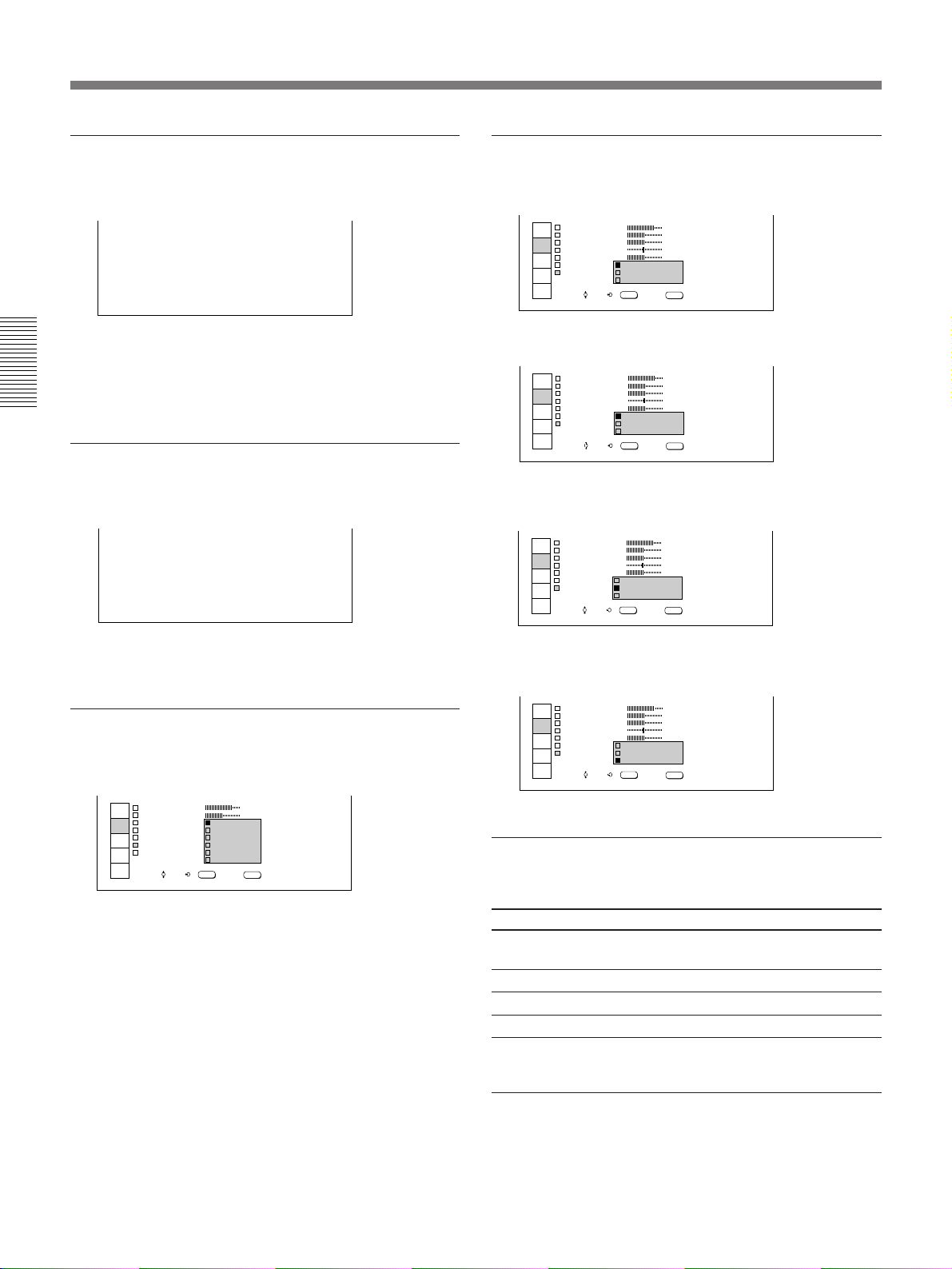
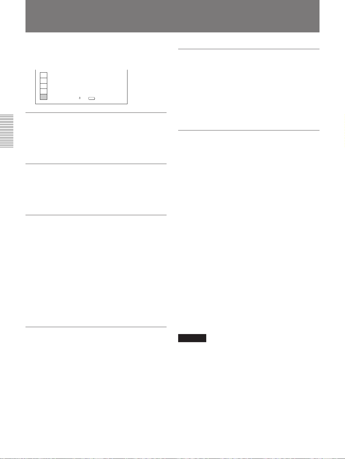
SIG TYPE (signal type)
Selects the normal, letter box, or squeeze signal.
P CTURE CTRL I
INPUT
CONTRAST
SELECT
BR GHTI
PICTURE
COLOR
CTRL
HUE
INPUT
SHARP
SETTING
COLOR SY
SET
S GI TYPE
SETTING
INPUT
INFO
SET:SEL: EXIT:
/
NORMAL: Normally set to this position.
P CTURE CTRL I
INPUT
CONTRAST
SELECT
BR GHTI
PICTURE
COLOR
CTRL
HUE
INPUT
SHARP
SETTING
COLOR SY
SET
S GI TYPE
SETTING
INPUT
INFO
SET:SEL: EXIT:
LETTER BOX: Set to this position when black
zones appear at the top and bottom of the screen.
P CTURE CTRL I
INPUT
CONTRAST
SELECT
BR GHTI
PICTURE
COLOR
CTRL
HUE
INPUT
SHARP
SETTING
COLOR SY
SET
S GI TYPE
SETTING
INPUT
INFO
SET:SEL: EXIT:
/
NORMAL
LETTER BOX
SQUEEZE
ENTER
NORMAL
LETTER BOX
SQUEEZE
ENTER
/
NORMAL
LETTER BOX
SQUEEZE
ENTER
80
50
50
50
50
80
50
50
50
50
80
50
50
50
50
MENU
MENU
MENU
The higher the setting level is, the sharper the picture.
The lower the setting level is, the softer the picture.
COLOR SYS (color system)
Selects the color system of the input signal.
P CTURE CTRL I
INPUT
CONTRAST
SELECT
BR GHTI
PICTURE
COLOR
CTRL
HUE
INPUT
SHARP
SETTING
COLOR SYS
SET
S GI TYPE :
SETTING
INPUT
INFO
SET:SEL: EXIT:
/
Normally set to AUTO.
If the picture is distorted or colorless, select the color
system corresponding to the input signal.
:
N
ENTER
AUTO
NTSC
PAL
SECAM
NTSC
PAL M-
80
50
3. 58
4. 43
MENU
SQUEEZE: Set to this position when a wide-screen
picture appears on the screen.
P CTURE CTRL I
INPUT
CONTRAST
SELECT
BR GHTI
PICTURE
COLOR
CTRL
HUE
INPUT
SHARP
SETTING
COLOR SY
SET
S GI TYPE
SETTING
INPUT
INFO
SET:SEL: EXIT:
NORMAL
LETTER BOX
SQUEEZE
ENTER
/
80
50
50
50
50
MENU
The items that cannot be adjusted
depending on the type of input signal
Item Cannot be adjusted with
COLOR HDTV signal, RGB (other than 15 kHz)
HUE Input signal other than on NTSC 3.58/4.43
SHARP RGB (other than 15 kHz) signal
COLOR SYS Signals other than video signal
SIG TYPE Input signal on PAL or SECAM, HDTV
signal or black-and-white signal
signal, RGB (other than 15 kHz/60 Hz)
signal or component signal
1)
..........................................................................................................................................................................................................
1) NTSC4.43 is the color system for playing back a video tape recorded on NTSC using an NTSC4.43 system VCR.
22 (EN)
Page 23
The INPUT SETTING Menu
The INPUT SETTING menu is used for adjusting the
input signal.
Adjustable items are displayed in green.
The INPUT SETTING menu consists of two pages.
To change the page, press the V or v key until the page
changes when selecting an item.
On the Remote Commander, move the joy stick up or
down until the page changes when selecting an item.
<Page 1>
INPUT
SELECT
PICTURE
CTRL
INPUT
SETTING
SET
SETTING
INPUT
INFO
NPUT SETT NGI
DOT PHASE
DOT
CLOCK
SH FTI::H
CLAMP
F LTER
I
SYNC SEL
COLOR
MEMORY:
I
:
4
123
123 :V 123
:
AUTO
OFF
:
: AUTO
: 6500
TEMP
MEMORY
RESET:
ENTER
SET:SEL: EXIT:
/
RESET
MENU
<Page 2>
INPUT
SELECT
PICTURE
CTRL
INPUT
SETTING
SET
SETTING
INPUT
INFO
NPUT SETT NGI
SCAN CONV::
BLKG
MEMORY:
I
ON
ON
MEMORY
RESET:
ENTER
SET:SEL: EXIT:
/
RESET
MENU
Note
Depending on the input signal, page 2 may not be
displayed.
4 Make adjustment or setting on the selected item.
When changing the adjustment level:
To increase the value, press the V or b key.
On the Remote Commander, move the joy stick up
or to the right.
To decrease the value, press the v or B key.
On the Remote Commander, move the joy stick
down or to the left.
To enter the value and return to the previous
screen, press the ENTER key.
When changing the setting:
Use the V or v key on the control panel to change
the setting, then press the B or ENTER key.
On the Remote Commander, move the joy stick up
or down to change the setting, then move it to the
left or press the ENTER key.
The previous screen is restored.
5 Press the MEMORY key on either the control
panel or the supplied Remote Commander after
adjustment or setting.
DOT PHASE
Adjustments and Settings Using the Menu
Operation
1 Press the MENU key.
The menu display appears.
The menu presently selected is highlighted in blue.
2 Select the INPUT SETTING menu using the V or
v key on the control panel, then press the b or
ENTER key.
On the Remote Commander, move the joy stick up
or down to select the INPUT SETTING menu,
then move it to the right or press the ENTER key.
Now you can select the item in the menu.
3 Select an item using the V or v key on the control
panel, then press the b or ENTER key.
On the Remote Commander, move the joy stick up
or down to select an item, then move it to the right
or press the ENTER key.
Adjusts the dot phase to fit picture pixel of the input
signal to that of DMD
TM 1)
.
Adjust the setting level to obtain the sharpest picture.
DOT PHASE :4
DOT CLOCK
Adjusts the horizontal length of the picture.
DOT
CLOCK : 123
(Continued)
..........................................................................................................................................................................................................
1) DMDTM is a trademark of Texas Instruments Incorporated, U.S.A.
23 (EN)
Page 24
The INPUT SETTING Menu
SHIFT
Adjusts the position of the picture.
SH FTI:H 123 :V 123
H (horizontal): Adjusts the horizontal position of
the picture. As the value increases, the picture
moves to the right. As the value decreases, the
picture moves to the left.
Adjustments and Settings Using the Menu
V (vertical): Adjusts the vertical position of the
picture. As the value increases, the picture moves
up. As the value decreases, the picture moves
down.
Use the B or the b key to adjust the horizontal
position, and the V or v key to adjust the vertical
position.
CLAMP
Corrects the luminance of the picture.
INPUT
SELECT
PICTURE
CTRL
INPUT
SETTING
SET
SETTING
INPUT
INFO
NPUT SETT NGI
DOT PHASE
DOT
CLOCK
SH FTI::H
CLAMP
I
F LTER
SYNC S TO
COLOR
CLAMP is used as a standard for correctly setting the
black level of a picture. The standard position of the
clamp depends on the kind of sync signal being used.
Normally, the projector CPU judges the signal and sets
the position automatically. However, the CPU can
misjudge the signal because of noise. If the luminance
of the picture seems to be incorrect, change the clamp
position.
AUTO: Automatic setting mode. Normally set to this
position.
SonG (sync on green): Set to this position if the
black seems too light or greenish.
H/C (horizontal/composite): Set to this position if
the picture is too dark or luminance is unstable.
I
:
4
123
123 :V 123
:
AUTO
SonG
H/C
TEMP
: 6500
MEMORY:
ENTER
SET:SEL: EXIT:
/
MEMORY
MENU
FILTER
Reduces the line patterns that appear on the picture.
INPUT
DOT PHASE
SELECT
DOT
PICTURE
SH FTI::H
CTRL
CLAMP
INPUT
F LTER
SETTING
SYNC SE TO
SET
COLOR
SETTING
INPUT
INFO
NPUT SETT NGI
CLOCK
I
I
:
4
123
123 :V 123
AUTO
:
ON
:
OFF
: 6500
TEMP
MEMORY:
ENTER
SET:SEL: EXIT:
/
MEMORY
MENU
The picture will lose some clarity, but the line patterns
will be reduced.
SYNC SEL (sync signal selection)
Selects the sync signal when both the S on G signal
and separate sync signal/composite sync signal are
input as RGB signals.
INPUT
DOT PHASE
SELECT
DOT
PICTURE
SH FTI::H
CTRL
CLAMP
INPUT
F LTER
I
SETTING
SYNC SEL :
SET
COLOR
SETTING
INPUT
INFO
NPUT SETT NGI
CLOCK
I
:
4
123
123 :V 123
:
AUTO
: OFF
AUTO
S
oGn
TEM
C,V/
H
MEMORY:
ENTER
SET:SEL: EXIT:
/
MEMORY
MENU
AUTO: Selects the sync signal automatically.
Normally set to this position.
SonG (sync on green): Selects the S on G signal.
H/C, V (horizontal/composite, vertical): Selects
the separate (horizontal/vertical) sync signal or
composite sync signal.
Note
If the luminance is still incorrect after changing the
clamp setting, check the input signal and the
connections.
COLOR TEMP (color temperature)
Selects the color temperature.
INPUT
SELECT
PICTURE
CTRL
INPUT
SETTING
SET
SETTING
INPUT
INFO
NPUT SETT NGI
DOT PHASE
DOT
CLOCK
SH FTI::H
CLAMP
I
F LTER
SYNC SEL : AU
COLOR
I
:
4
123
123
9300
AUTO
:
6500
: OFF
5400
3200
:
TEMP
PRESET
MEMORY:
ENTER
SET:SEL: EXIT:
/
MEMORY
MENU
Note
If the luminance is still incorrect after changing the
clamp setting, check the input signal and the
connections.
24 (EN)
Page 25
SCAN CONV (scan convertor)
Change the setting when the input signal is other than
800 × 600 pixels.
INPUT
SELECT
PICTURE
CTRL
INPUT
SETTING
SET
SETTING
INPUT
INFO
NPUT SETT NGI
SCAN CONV::
BLKG
ON: Displays the picture according to the screen size.
The picture will lose some clarity.
OFF: Displays the picture while matching one pixel
of input picture elements to that of the DMD. The
picture will be clear. When the input signal is
more than 800 × 600 pixels, a part of the screen
may be cut off.
Notes
• When you switch the input signal, the size of the
picture may be changed.
• You may not be able to select OFF when the vertical
frequency of the input signal is 62 Hz or less and the
horizontal frequency is 60 kHz or more.
I
ON
OFF
ON
MEMORY:
ENTER
SET:SEL: EXIT:
/
MEMORY
MENU
The items that cannot be adjusted
depending on the type of input signal
Item Cannot be adjusted with
DOT PHASE Signals other than RGB signal (except 15
kHz)
DOT CLOCK Signals other than RGB signal (except 15
kHz)
SHIFT Signals other than RGB signal (except 15
kHz)
CLAMP Signals other than RGB signal (except 15
kHz)
FILTER Signals other than RGB signal (except 15
kHz)
SCAN CONV Composite video, Y/C video input signal,
HDTV signal or some input signals at
horizontal frequency of 62 Hz or less or at
vertical frequency of 60 kHz or more
BLKG RGB signal (except 15 kHz)
Adjustments and Settings Using the Menu
BLKG (blanking)
Set to ON to mask the upper, lower, left and right parts
of the screen. A noise on these parts will be reduced
(“ON” is the factory setting.)
Set to OFF if necessary as the picture to be displayed
is small.
INPUT
SELECT
PICTURE
CTRL
INPUT
SETTING
SET
SETTING
INPUT
INFO
NPUT SETT NGII
SCAN CONV::
BLKG
ON
ON
OFF
MEMORY:
ENTER
SET:SEL: EXIT:
/
MEMORY
MENU
25 (EN)
Page 26
The SET SETTING Menu
The SET SETTING menu is used for changing the
default settings.
Adjustable items are displayed in green.
The SET SETTING menu consists of three pages.
To change the page, press the V or v key until the page
changes when selecting an item.
On the Remote Commander, move the joy stick up or
down until the page changes when selecting an item.
<Page 1>
INPUT
SELECT
PICTURE
CTRL
INPUT
SETTING
Adjustments and Settings Using the Menu
SET
SETTING
INPUT
INFO
SET SETT NG
FOCUS
ZOOM
P CTUREI
STATUS
I
P C
I NPUT- A
I NPUT- B :RGB
I
SH FTI
O
:
N
: OFF
MUT NGI
:RGB
ENTER
SET:SEL: EXIT:
/
MENU
<Page 2>
INPUT
SELECT
PICTURE
CTRL
INPUT
SETTING
SET
SETTING
INPUT
INFO
SET SETT NG
LANGUAGE
H
POLAR TY
V POLAR TY
POWER
L GHT
I
IS RCS
I
: ENGL SHI
NORMAL
I
:
:
NORMAL
I
SAV NG
I : OFF
:O
N
BOOST
I
RECE VER
FRONT&REAR
ENTER
SET:SEL: EXIT:
/
MENU
<Page 3>
INPUT
SELECT
PICTURE
CTRL
INPUT
SETTING
SET
SETTING
INPUT
INFO
SET SETT NGI
1
:S
SCREEN
CONPONENT
SMPTE
NDEX
1
I:0
SET:SEL: EXIT:
/
FORMAT
/ EBU N1 0
ENTER
:
-
MENU
Operation
3 Select an item using the V or v key on the control
panel, then press the b or ENTER key.
On the Remote Commander, move the joy stick up
or down to select an item, then move it to the right
or press the ENTER key.
4 Make adjustment or setting on the selected item.
When changing the adjustment level:
To increase the value, press the V or b key.
On the Remote Commander, move the joy stick up
or to the right.
To decrease the value, press the v or B key.
On the Remote Commander, move the joy stick
down or to the left.
To enter the value and return to the previous
screen, press the ENTER key.
When changing the setting:
Use the V or v key on the control panel to change
the setting, then press the B or ENTER key.
On the Remote Commander, move the joy stick up
or down to change the setting, then move it to the
left or press the ENTER key.
The previous screen is restored.
FOCUS
Adjusts the focus.
1 Press the MENU key.
The menu display appears.
The menu presently selected is highlighted in blue.
2 Select the SET SETTING menu using the V or v
key on the control panel, then press the b or
ENTER key.
On the Remote Commander, move the joy stick up
or down to select the SET SETTING menu, then
move it to the right or press the ENTER key.
Now you can select the item in the menu.
26 (EN)
+
FOCUS
To adjust the focus, press the V/b key or v/B key. On
the Remote Commander, move the joy stick up/right or
down/left.
Page 27
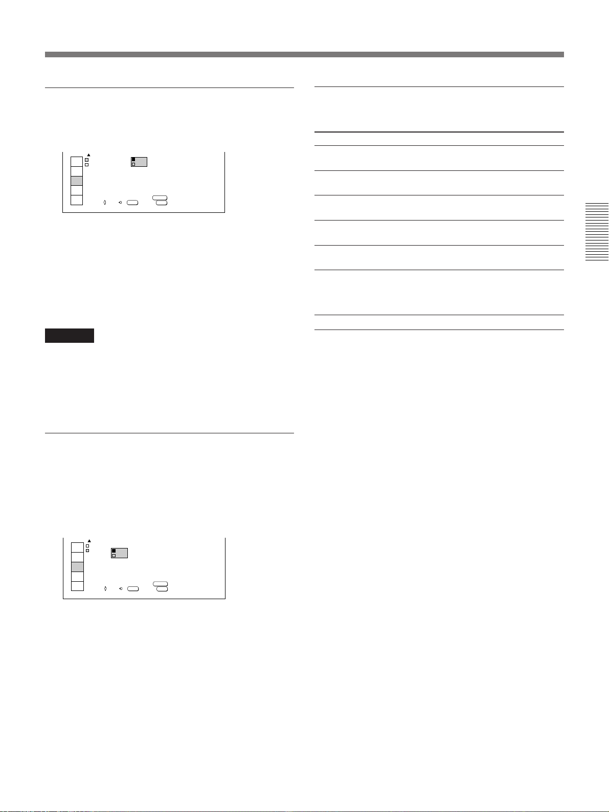
ZOOM
PIC MUTING (picture muting)
Adjusts the zoom.
+
ZOOM
To zoom in, press the V or b key. On the Remote
Commander, move the joy stick up or to the right.
To zoom out, press the v or B key. On the Remote
Commander, move the joy stick down or to the left.
Note
When the VPDL-FP30 fixed short focus lens is
attached to the projector, you cannot use the zoom
function.
PICTURE SHIFT
Adjusts the vertical position of the picture.
Set to ON to cut off the picture.
When set to ON, “PIC MUTING” appears on the
screen.
INPUT
SELECT
PICTURE
CTRL
INPUT
SETTING
SET
SETTING
INPUT
INFO
SET SETT NG
FOCUS
ZOOM
P CTUREI
STATUS
I
P C
I NPUT- A
I NPUT- B
I
SH FTI
ON
:
ON
:
MUT NGI
RGB
:
OFF
RGB
:
ENTER
SET:SEL: EXIT:
/
MENU
INPUT-A
Selects the RGB or component signal input from the
INPUT A connectors.
INPUT
SELECT
PICTURE
CTRL
INPUT
SETTING
SET
SETTING
INPUT
INFO
SET SETT NG
FOCUS
ZOOM
P CTUREI
STATUS
I
P C
I NPUT- A
I NPUT- B
Note
Unless the signal type is correctly selected, the picture
noise may appear. For example, color balance may be
incorrect.
I
SH FTI
ON
:
: OFF
MUT NGI
RGB
:
COMPOMENT
:
ENTER
SET:SEL: EXIT:
/
MENU
Adjustments and Settings Using the Menu
PICTURE SHIFT
+
To move the picture up, press the V or b key. On the
Remote Commander, move the joy stick up or to the
right.
To move the picture down, press the v or B key. On
the Remote Commander, move the joy stick down or
to the left.
STATUS (on-screen display)
Sets up the on-screen display.
INPUT
SELECT
PICTURE
CTRL
INPUT
SETTING
SET
SETTING
INPUT
INFO
SET SETT NG
FOCUS
ZOOM
P CTUREI
STATUS
I
P C
I NPUT- A
I NPUT- B :RGB
ON: Displays all the on-screen displays.
OFF: Turns off the on-screen displays except “NO
INPUT,” “PIC MUTING,” and warning messages.
ALL OFF: Turns off all the on-screen displays
except warning messages.
I
SH FTI
ON
:
OFF
MUT
A OFFLL
ENTER
SET:SEL: EXIT:
/
MENU
INPUT-B
Selects the RGB, component, composite video or Svideo signal input from the connectors on the IFB-12
Signal Interface Board (not supplied) installed in the
INPUT B slot of the projector.
INPUT
SELECT
PICTURE
CTRL
INPUT
SETTING
SET
SETTING
INPUT
INFO
SET SETT NG
FOCUS
ZOOM
P CTUREI
STATUS
I
P C
I NPUT- A
I NPUT- B
Notes
• You cannot select this item when you have not
installed the IFB-12 Signal Interface Board (not
supplied) in the projector.
• Unless the signal type is correctly selected, the
picture noise may appear. For example, color balance
may be incorrect.
I
SH FTI
ON
:
RGB
MUT I
COMPONENT
:
V DEO
I
:
V DEO
S
I
-
ENTER
SET:SEL: EXIT:
/
MENU
(Continued)
27 (EN)
Page 28
The SET SETTING Menu
LANGUAGE
Selects the language used for the menu and on screen
displays.
INPUT
SELECT
PICTURE
CTRL
INPUT
SETTING
SET
SETTING
INPUT
INFO
SET SETT NG
LANGUAGE
H
POLAR T
V POLAR T
POWER
L GHT
I
IS RCS
I
ENGL SH
:
I
I
FRANCA S
DEUTSCH
I
SAV
TAL ANO
I
I
ESPANOL
BOO
I
RECE VER
FRONT&REAR
ENTER
SET:SEL: EXIT:
/
I
MENU
Available languages are English, French, German,
Italian, and Spanish.
Adjustments and Settings Using the Menu
H POLARITY (horizontal polarity)
Set to REVERSE to reverse the horizontal orientation
of the picture.
INPUT
SELECT
PICTURE
CTRL
INPUT
SETTING
SET
SETTING
INPUT
INFO
SET SETT NG
LANGUAGE
H
POLAR TY
V POLAR TY
POWER
L GHT
I
IS RCS
I
: ENGL SHI
NORMAL
I
:
:
REVERSE
I
SAV NG
I : OFF
:O
N
BOOST
I
RECE VER
FRONT&REAR
ENTER
SET:SEL: EXIT:
/
MENU
LIGHT BOOST
When you set this item to ON, the lamp power is
boosted and the display gets brighter. You can select
ON when you use the projector at 200 to 240 V.
If you use the projector at 100 to 120 V, you cannot
select this item.
INPUT
SELECT
PICTURE
CTRL
INPUT
SETTING
SET
SETTING
INPUT
INFO
SET SETT NG
LANGUAGE
H
POLAR TY
V POLAR TY
POWER
L GHT
I
IS RCS
I
: ENGL SHI
NORMAL
I
:
:
REVERSE
I
SAV NG
:
OFF
I
ON
:
BOOST
OFF
I
RECE V
FRONT&REAR
ENTER
SET:SEL: EXIT:
/
MENU
SIRCS RECEIVER
Selects the remote control detectors on the front or rear
of the projector.
INPUT
SELECT
PICTURE
CTRL
INPUT
SETTING
SET
SETTING
INPUT
INFO
SET SETT NG
LANGUAGE
H
POLAR TY
V POLAR TY
POWER
L GHT
I
IS RCS
I
: ENGL SHI
NORMAL
I
:
:
NORMAL
I
SAV NG
:
OFF
I
:
BOOST
ON
FRONT&REAR
RE
FRONT
REAR
ENTER
SET:SEL: EXIT:
/
MENU
V POLARITY (vertical polarity)
Set to REVERSE to reverse the vertical orientation of
the picture.
INPUT
SELECT
PICTURE
CTRL
INPUT
SETTING
SET
SETTING
INPUT
INFO
SET SETT NG
LANGUAGE
POLAR TY
H
V POLAR TY
POWER
L GHT
I
IS RCS
I
: ENGL SHI
NORMAL
:
I
:
NORMAL
I
SAV N
I
REVERSE
N
:O
BOOST
I
RECE VER
FRONT&REAR
ENTER
SET:SEL: EXIT:
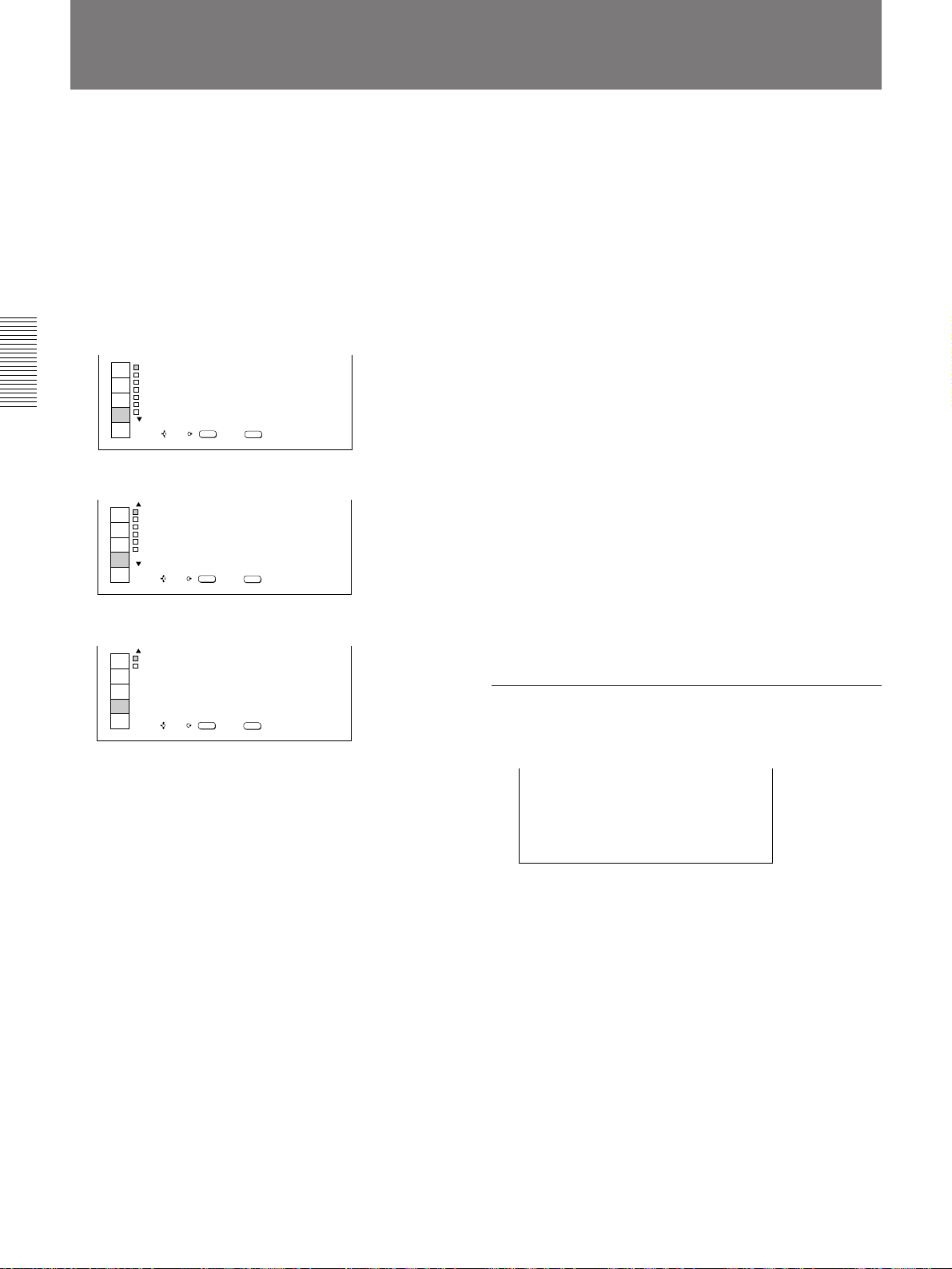
/
MENU
POWER SAVING
Set to ON to enter the power saving mode.
When no signal is input for 10 minutes or more, the
projector goes into the power saving mode, and the
lamp goes off. The power saving mode is released
when any key is pressed.
INPUT
SELECT
PICTURE
CTRL
INPUT
SETTING
SET
SETTING
INPUT
INFO
SET SETT NG
LANGUAGE
H
POLAR TY
V POLAR TY
POWER
L GHT
I
IS RCS
I
: ENGL SHI
NORMAL
I
:
:
NORMAL
I
SAV NG
BOOST
RECE VER
SET:SEL: EXIT:
ON
:
I
OFF
:O
:
I
FRONT&REAR
ENTER
/
MENU
FRONT & REAR: Activates both the front and rear
detectors.
FRONT: Activates the front detector only.
REAR: Activates the rear detector only.
SCREEN
Selects “S1” or “S2” according to the screen.
INPUT
SELECT
PICTURE
CTRL
INPUT
SETTING
SET
SETTING
INPUT
INFO
S1: Set to this position when you use a “bead”
screen. (Glass particles are spread over the screen
surface.)
S2: Set to this position when you use a mat screen.
(normal screen)
SET SETT NGI
SCREEN
COMPONT
SMPTE
NDEX
I
SET:SEL: EXIT:
S
1
:
FORMAT
S2
:
0
/
/ EBU1N1
ENTER
:
-
0
MENU
28 (EN)
Page 29
COMPONENT FORMAT
Selects the format of the component input signal.
INPUT
SELECT
PICTURE
CTRL
INPUT
SETTING
SET
SETTING
INPUT
INFO
SET SETT NGI
SCREEN
COMPO
NDEX
I
SET:SEL: EXIT:
S
:
SMPTE1/ EBU1N1
BETACAM 7
:
0
ENTER
/
0
-
5.
MENU
SMPTE/EBU-N10: Set to this position when the
input signal conforms to the SMPTE/EBU-N10
level.
BETACAM 7.5: Set to this position when the input
signal is in BETACAM 7.5 format.
INDEX
Displays the index number set with the INDEX
switches on the rear of the projector.
The item that cannot be adjusted
depending on the type of input signal
Item Cannot be adjusted with
COMPONENT Signals other than component signal
FORMAT
Adjustments and Settings Using the Menu
29 (EN)
Page 30
The INPUT INFO Menu
The INPUT INFO menu displays information on the
input signal being used.
NPUT NFO
I
:H
31 . 4KHz
SYNC
NEG
nG :
I
NEG
:
NEGSYNC
:
S GNAL
I
:
RGB
SEL: EXIT:
MENU
INPUT
SELECT
PICTURE
CTRL
INPUT
SETTING
SET
SETTING
INPUT
INFO
f
f:V59.9Hz
HC
/
V
S
o
I NPUT
MEMORY NO . 6
fH (horizontal frequency)
Indicates the horizontal frequency of the input signal.
Use this indication as a reference. This is not the
absolute value.
Adjustments and Settings Using the Menu
fV (vertical frequency)
Indicates the vertical frequency of the input signal.
Use this indication as a reference. This is not the
absolute value.
H/C SYNC (horizontal/composite sync
signal)
Indicates the polarity of the horizontal or composite
sync signal. When the picture is projected with the
sync signal, POS or NEG is displayed in green. When
the picture is projected without the sync signal, POS or
NEG is displayed in white.
POS (positive): The polarity of the sync signal is
positive.
NEG (negative): The polarity of the sync signal is
negative.
---: No sync signal is input.
V SYNC (vertical sync signal)
Indicates the polarity of the vertical sync signal. When
the picture is projected with the sync signal, POS or
NEG is displayed in green. When the picture is
projected without the sync signal, POS or NEG is
displayed in white.
POS (positive): The polarity of the sync signal is
positive.
NEG (negative): The polarity of the sync signal is
negative.
---: No sync signal is input.
SonG (sync on green)
Indicates the polarity of the sync on green. When the
picture is projected with the sync signal, NEG is
displayed in green. When the picture is projected
without the sync signal, NEG is displayed in white.
NEG (negative): The polarity of the sync signal is
negative.
---: No sync signal is input.
INPUT SIGNAL
Indicates the type of the input signal.
NTSC 3.58: Video signal on NTSC 3.58 color
system
PAL: Video signal on PAL color system
SECAM: Video signal on SECAM color system
NTSC 4.43: Video signal on NTSC 4.43 color
system
PAL-M: Video signal on PAL-M color system
B&W: Black and white video signal
COMPONENT: Component video signal
RGB: RGB signal
NTSC 3.58 S-VIDEO: S-video signal based on
NTSC 3.58 color system
PAL S-VIDEO: S-video signal based on PAL color
system
SECAM S-VIDEO: S-video signal based on
SECAM color system
NTSC 4.43 S-VIDEO: S-video signal based on
NTSC 4.43 color system
PAL-M S-VIDEO: S-video signal based on PAL M
color system
B&W S-VIDEO: Black and white S-video signal
HDTV: Signal on 1125/60 interlaced HDTV studio
standard system
Notes
• To input the HDTV signal, the IFB-1301 (not
supplied) should be inserted in the signal interface
board attachment part (INPUT B).
• Because of the limited pixel number of the DMD, the
original resolution of the HDTV cannot be
reproduced.
30 (EN)
Page 31

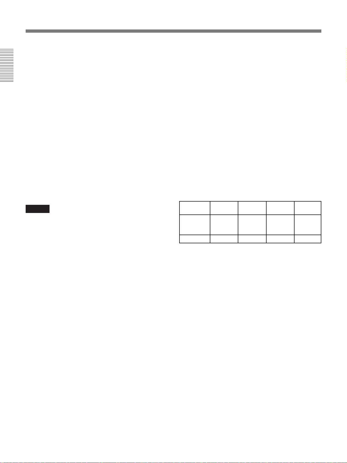
Preset Data List
Types of preset signals, fH (horizontal frequency), fV
(vertical frequency) and sync signals are listed below.
Preset signal fH (kHz) fV (Hz) Sync
Video 60 Hz 15.734 59.94 —
Video 50 Hz 15.625 50.0 —
15k RGB/ 15.734 59.94 C sync /
Component 60 Hz S on G
15k RGB/ 15.625 50.0 C sync /
Component 50 Hz S on G
1)
1 (640×350) 31.468 70.086 H-pos
VGA
VGA 2 (640×400) 31.468 70.086 H-neg
VGA 3 Graphics 31.468 59.940 H-neg
(640×480) V-neg
IBM 8514A/XGA 35.524 43.478 H-pos
IBM XGA 2-3 61.080 75.781 —
2)
VGA (fV:72 Hz) 37.860 72.809 H-neg
VESA
VESA VGA (fV:75 Hz) 37.500 75.000 H-neg
VESA VGA (fV:85 Hz) 43.269 85.008 H-neg
VESA S VGA 1 35.156 56.250 H-neg
(fV:56 Hz) V-neg
VESA S VGA 2 37.879 60.317 H-pos
(fV:60 Hz) V-pos
VESA S VGA 3 48.077 72.188 H-pos
(fV:72 Hz) V-pos
VESA S VGA 4 46.875 75.000 H-pos
(fV:75 Hz) V-pos
VESA S VGA 5 53.674 85.061 H-pos
(fV:85 Hz) V-pos
VESA XGA 1 48.363 60.000 H-neg
(fV:60 Hz) V-neg
VESA XGA 2 56.476 70.069 H-neg
(fV:70 Hz) V-neg
VESA XGA 3 60.023 75.029 H-pos
(fV:75 Hz) V-pos
VESA 1280 × 1024 63.981 60.020 H-pos
(fV:60 Hz) V-pos
IBM PS-55 1 46.474 115.200 H-pos
IBM PS-55 2 45.995 116.000 H-pos
V-neg
V-pos
V-pos
V-neg
V-neg
V-neg
V-pos
V-pos
Preset signal fH (kHz) fV (Hz) Sync
Macintosh
Macintosh 13" Mode 35.0 66.667 S on G
Macintosh 16" Mode 49.724 74.550 H-neg
Macintosh 19" Mode 60.241 74.927 H-neg
Macintosh 48.190 74.550 S on G
Super mac 1
NEC
Normal mode V-neg
NEC H98 Hi reso 32.840 80.000 H-neg
Sony News 63.337 59.978 S on G
Sony News 63.337 59.978 H-neg
Sunmicro 61.800 65.9 H-neg
Silicon Graphics 48.732 59.94 S on G
Silicon Graphics 63.839 59.943 S on G
HDTV
13" Mode 35.0 66.645 H-neg
3)
PC9801 24.83 56.4 H-neg
4)
33.750 60.000 S on G
V-neg
V-neg
V-neg
V-neg
V-neg
V-neg
Notes
• With video input signals, “SCAN CONV” cannot be
set to OFF.
• When the resolution is 1024 × 768 pixels or more,
you may not set “SCAN CONV” to OFF.
Adjustments and Settings Using the Menu
.........................................................................................................................................................................................................
1) VGA is a trademark of the International Business Machines Corporation, U.S.A.
2) VESA is a trademark of Video Electronics Standard Association.
3) NEC is a trademark of the NEC Corporation.
4) 1125/60 interlaced HDTV studio standard. You need to install the IFB-1301 Interface Board (not supplied).
31 (EN)
Page 32

Installation Examples
About the Installation of the
Projector
Even if the temperature of the environment is in
acceptable range (10˚C to 35˚C (50˚F to 95˚F)), the
protection circuit may turn the projector (or the lamp)
off automatically due to internal heat build-up if an air
circulation around the projector is inadequate.
The projector inhales air from the ventilation holes
located on the front panel and the sides, and exhausts
from the ventilation holes located on the rear panel.
The following are recommended so that exhaust
around the rear panel does not flow into the ventilation
holes on the front panel and sides.
• Install an air conditioner so that cool air blows to the
Installation/Connection Examples
projector. Be sure not to block the projection light
with the ventilator of the air conditioner.
Air conditioner
Cool air
Ventilation hole
• The air from the projector exhausts downward at an
angle of 45˚. Place a stand for installation so that the
stand does not block the exhaust.
Do not block the exhaust.
• Even if enough space cannot be provided between the
wall and the projector, leave a space of 30 cm (11
7
/8
inches) at the minimum.
• When you perform stack installation in a location
where enough space cannot be provided between the
wall and the projectors, leave a minimum of the
following space depending on the number of stacked
projectors:
N: number of stacked projectors
Minimum space: N x 30 cm (11
7
/8 inches)
32 (EN)
Top view
Page 33

Floor Installation
Wall
x
Center of the screen
Center of the lens
Installation/Connection Examples
b
c
Installation/Connection Examples
a
a: Distance between the screen and the center of the lens
b: Distance from the floor to the center of the lens
c: Distance from the floor to the bottom of the projector
x: Free
To calculate the installation measurement
(unit:mm)
SS: screen size diagonal (inches)
When using the VPDL-ZP50 1.5 times zoom standard
focus lens
a (minimum): (1+SS × 25.4/17) × 35–61.2
a (maximum): (1+SS × 25.4/17) × 52.5–37.1
b (minimum): X–SS × 25.4 × 0.3
b (maximum): X+SS × 25.4 × 0.3
c (minimum): X–SS × 25.4 × 0.3–180
c (maximum): X+SS × 25.4 × 0.3–160
Floor
When using the VPDL-ZP80 2 times zoom long focus
lens
a (minimum): (1+SS × 25.4/17) × 52.5–103.9
a (maximum): (1+SS × 25.4/17) × 105–176.5
b (minimum): X–SS × 25.4 × 0.3
b (maximum): X+SS × 25.4 × 0.3
c (minimum): X–SS × 25.4 × 0.3–180
c (maximum): X+SS × 25.4 × 0.3–160
When using the VPDL-FP30 fixed short focus lens
a: (1+SS × 25.4/17) × 17.5–35.5
b (minimum): X–SS × 25.4 × 0.3
b (maximum): X+SS × 25.4 × 0.3
c (minimum): X–SS × 25.4 × 0.3–180
c (maximum): X+SS × 25.4 × 0.3–160
(Continued)
33 (EN)
Page 34

Installation Examples
When using the VPDL-ZP50 1.5 times zoom standard focus lens
Screen size (inches) 100 120 150 180 200 250 300 350 400 500 600
Minimum
a
Maximum
Minimum
b
Maximum
Minimum
c
Maximum
When using the VPDL-ZP80 2 times zoom long focus lens
Installation/Connection Examples
Screen size (inches) 100 120 150 180 200 250 300 350 400 500 600
Minimum
a
Maximum
Minimum
b
Maximum
Minimum
c
Maximum
5200 6250 7820 9390 10430 13050 15660 18280 20890 26120 31350
(204 7/8) (246 1/8) (307 7/8) (369 5/8) (410 3/4) (513 3/4) (616 5/8) (719 5/8) (822 1/2) (1028 1/2) (1234 3/8)
7860 9430 11780 14130 15700 19630 23550 27470 31390 39240 47080
(309 1/2) (371 1/4) (463 7/8) (556 1/2) (618 3/8) (772 3/4) (927 1/8) (1081 1/2) (1236) (1544 3/4) (1853 5/8)
x–762 x–914 x–1143 x–1372 x–1524 x–1905 x–2286 x–2667 x–3048 x–3810 x–4572
(30) (36) (45) (54) (60) (75) (90) (105) (120) (150) (180)
x+762 x+914 x+1143 x+1372 x+1524 x+1905 x+2286 x+2667 x+3048 x+3810 x+4572
(30) (36) (45) (54) (60) (75) (90) (105) (120) (150) (180)
x–942 x–1094 x–1323 x–1552 x–1704 x–2085 x–2466 x–2847 x–3228 x–3990 x–4752
(37 1/8) (43 1/8) (52 1/8) (61 1/8) (67 1/8) (82 1/8) (97 1/8) (112 1/8) (127 1/8) (157 1/8) (187 1/8)
x+602 x+754 x+983 x+1212 x+1364 x+1745 x+2126 x+2507 x+2888 x+3650 x+4412
(23 3/4) (29 3/4) (38 3/4) (47 3/4) (53 3/4) (68 3/4) (83 3/4) (98 3/4) (113 3/4) (143 3/4) (173 3/4)
7790 9360 11710 14070 15640 19560 23480 27400 31330 39170 47010
(306 7/8) (368 5/8) (461 1/4) (553 7/8) (615 5/8) (770 1/8) (924 1/2) (1078 7/8) (1233 3/8) (1542 1/8) (1851)
15620 18750 23460 28170 31300 39150 46990 54840 62680 78370 94060
(614 7/8) (738 3/8) (923 3/4) (1109) (1232 1/2) (1541 3/8) (1850 1/4) (2159) (2467 7/8) (3085 1/2) (3703 1/8)
x–762 x–914 x–1143 x–1372 x–1524 x–1905 x–2286 x–2667 x–3048 x–3810 x–4572
(30) (36) (45) (54) (60) (75) (90) (105) (120) (150) (180)
x+762 x+914 x+1143 x+1372 x+1524 x+1905 x+2286 x+2667 x+3048 x+3810 x+4572
(30) (36) (45) (54) (60) (75) (90) (105) (120) (150) (180)
x–942 x–1094 x–1323 x–1552 x–1704 x–2085 x–2466 x–2847 x–3228 x–3990 x–4752
(37 1/8) (43 1/8) (52 1/8) (61 1/8) (67 1/8) (82 1/8) (97 1/8) (112 1/8) (127 1/8) (157 1/8) (187 1/8)
x+602 x+754 x+983 x+1212 x+1364 x+1745 x+2126 x+2507 x+2888 x+3650 x+4412
(23 3/4) (29 3/4) (38 3/4) (47 3/4) (53 3/4) (68 3/4) (83 3/4) (98 3/4) (113 3/4) (143 3/4) (173 3/4)
Unit: mm (inches)
Unit: mm (inches)
When using the VPDL-FP30 fixed short focus lens
Unit: mm (inches)
Screen size (inches) 100 120 150 180 200 250 300 350 400 500 600
a
Minimum
b
Maximum
Minimum
c
Maximum
2600 3120 3900 4690 5210 6520 7830 9130 10440 13060 15670
(102 1/4) (122 7/8) (153 3/4) (184 5/8) (205 1/4) (256 3/4) (308 1/8) (359 5/8) (411 1/8) (514) (617)
x–762 x–914 x–1143 x–1372 x–1524 x–1905 x–2286 x–2667 x–3048 x–3810 x–4572
(30) (36) (45) (54) (60) (75) (90) (105) (120) (150) (180)
x+762 x+914 x+1143 x+1372 x+1524 x+1905 x+2286 x+2667 x+3048 x+3810 x+4572
(30) (36) (45) (54) (60) (75) (90) (105) (120) (150) (180)
x–942 x–1094 x–1323 x–1552 x–1704 x–2085 x–2466 x–2847 x–3228 x–3990 x–4752
(37 1/8) (43 1/8) (52 1/8) (61 1/8) (67 1/8) (82 1/8) (97 1/8) (112 1/8) (127 1/8) (157 1/8) (187 1/8)
x+602 x+754 x+983 x+1212 x+1364 x+1745 x+2126 x+2507 x+2888 x+3650 x+4412
(23 3/4) (29 3/4) (38 3/4) (47 3/4) (53 3/4) (68 3/4) (83 3/4) (98 3/4) (113 3/4) (143 3/4) (173 3/4)
Note on the installation measurement “c”
To secure enough space, make sure that “c” is more than 500mm (19
3
/4 inches).
34 (EN)
Page 35

Ceiling Installation
For ceiling installation, consult qualified service personnel.
Center of the screen
d
Projector Suspension Support PSS-70
(not supplied)
a
Ceiling
b
c
Center of the lens
Installation/Connection Examples
Wall
a: Distance between the screen and the center of lens
b: Distance between the ceiling and the bottom of the projector
c: Distance between the ceiling and the center of the lens
d: Distance between the ceiling and the center of the screen
To calculate the installation measurement
(unit:mm)
SS: screen size diagonal (inches)
When using the VPDL-ZP50 1.5 times zoom standard
focus lens
a (minimum): (1+SS × 25.4/17) × 35–61.2
a (maximum): (1+SS × 25.4/17) × 52.5–37.1
c (minimum): b+SS/250+153
c (maximum): b+155
d (minimum): SS × 25.4 × 0.3
d (maximum): b+SS × 25.4 × 0.3+155
When using the VPDL-ZP80 2 times zoom long focus
lens
a (minimum): (1+SS × 25.4/17) × 52.5–103.9
a (maximum): (1+SS × 25.4/17) × 105–176.5
c (minimum): b+SS/250+153
c (maximum): b+155
d (minimum): SS × 25.4 × 0.3
d (maximum): b+SS × 25.4 × 0.3+155
When using the VPDL-FP30 fixed short focus lens
a: (1+SS × 25.4/17) × 17.5–35.5
c (minimum): b+SS/250+153
c (maximum): b+155
d (minimum): SS × 25.4 × 0.3
d (maximum): b+SS × 25.4 × 0.3+155
(Continued)
35 (EN)
Page 36

Installation Examples
When using the VPDL-ZP50 1.5 times zoom standard focus lens
Screen size (inches) 100 120 150 180 200 250 300 350 400 500 600
Minimum
a
Maximum
b
Minimum
c
Maximum
Minimum
d
Maximum
Installation/Connection Examples
When using the VPDL-ZP80 2 times zoom long focus lens
Screen size (inches) 100 120 150 180 200 250 300 350 400 500 600
Minimum
a
Maximum
b
Minimum
c
Maximum
Minimum
d
Maximum
5200 6250 7820 9390 10430 13050 15660 18280 20890 26120 31350
(204 7/8) (246 1/8) (307 7/8) (369 5/8) (410 3/4) (513 3/4) (616 5/8) (719 5/8) (822 1/2) (1028 1/2) (1234 3/8)
7860 9430 11780 14130 15700 19630 23550 27470 31390 39240 47080
(309 1/2) (371 1/4) (463 7/8) (556 1/2) (618 3/8) (772 3/4) (927 1/8) (1081 1/2) (1236) (1544 3/4) (1853 5/8)
115 115 115 115 115 115 115 115 115 115 115
(4 5/8) (4 5/8) (4 5/8) (4 5/8) (4 5/8) (4 5/8) (4 5/8) (4 5/8) (4 5/8) (4 5/8) (4 5/8)
b+153 b+153 b+154 b+154 b+154 b+154 b+154 b+154 b+155 b+155 b+155
(6 1/8) (6 1/8) (6 1/8) (6 1/8) (6 1/8) (6 1/8) (6 1/8) (6 1/8) (6 1/8) (6 1/8) (6 1/8)
b+155 b+155 b+155 b+155 b+155 b+155 b+155 b+155 b+155 b+155 b+155
(6 1/8) (6 1/8) (6 1/8) (6 1/8) (6 1/8) (6 1/8) (6 1/8) (6 1/8) (6 1/8) (6 1/8) (6 1/8)
762 914 1143 1372 1524 1905 2286 2667 3048 3810 4572
(30) (36) (45) (54) (60) (75) (90) (105) (120) (150) (180)
b+917 b+1069 b+1298 b+1527 b+1679 b+2060 b+2441 b+2822 b+3203 b+3965 b+4727
(36 1/8) (42 1/8) (51 1/8) (60 1/8) (66 1/8) (81 1/8) (96 1/8) (111 1/8) (126 1/8) (156 1/8) (186 1/8)
7790 9360 11710 14070 15640 19560 23480 27400 31330 39170 47010
(306 7/8) (368 5/8) (461 1/4) (553 7/8) (615 5/8) (770 1/8) (924 1/2) (1078 7/8) (1233 3/8) (1542 1/8) (1851)
15620 18750 23460 28170 31300 39150 46990 54840 62680 78370 94060
(614 7/8) (738 3/8) (923 3/4) (1109) (1232 1/2) (1541 3/8) (1850 1/4) (2159) (2467 7/8) (3085 1/2) (3703 1/8)
115 115 115 115 115 115 115 115 115 115 115
(4 5/8) (4 5/8) (4 5/8) (4 5/8) (4 5/8) (4 5/8) (4 5/8) (4 5/8) (4 5/8) (4 5/8) (4 5/8)
b+153 b+153 b+154 b+154 b+154 b+154 b+154 b+154 b+155 b+155 b+155
(6 1/8) (6 1/8) (6 1/8) (6 1/8) (6 1/8) (6 1/8) (6 1/8) (6 1/8) (6 1/8) (6 1/8) (6 1/8)
b+155 b+155 b+155 b+155 b+155 b+155 b+155 b+155 b+155 b+155 b+155
(6 1/8) (6 1/8) (6 1/8) (6 1/8) (6 1/8) (6 1/8) (6 1/8) (6 1/8) (6 1/8) (6 1/8) (6 1/8)
762 914 1143 1372 1524 1905 2286 2667 3048 3810 4572
(30) (36) (45) (54) (60) (75) (90) (105) (120) (150) (180)
b+917 b+1069 b+1298 b+1527 b+1679 b+2060 b+2441 b+2822 b+3203 b+3965 b+4727
(36 1/8) (42 1/8) (51 1/8) (60 1/8) (66 1/8) (81 1/8) (96 1/8) (111 1/8) (126 1/8) (156 1/8) (186 1/8)
Unit: mm (inches)
Unit: mm (inches)
When using the VPDL-FP30 fixed short focus lens
Unit: mm (inches)
Screen size (inches) 100 120 150 180 200 250 300 350 400 500 600
a
b
Minimum
c
Maximum
Minimum
d
Maximum
2600 3120 3900 4690 5210 6520 7830 9130 10440 13060 15670
(102 1/4) (122 7/8) (153 3/4) (184 5/8) (205 1/4) (256 3/4) (308 1/8) (359 5/8) (411 1/8) (514) (617)
115 115 115 115 115 115 115 115 115 115 115
(4 5/8) (4 5/8) (4 5/8) (4 5/8) (4 5/8) (4 5/8) (4 5/8) (4 5/8) (4 5/8) (4 5/8) (4 5/8)
b+153 b+153 b+154 b+154 b+154 b+154 b+154 b+154 b+155 b+155 b+155
(6 1/8) (6 1/8) (6 1/8) (6 1/8) (6 1/8) (6 1/8) (6 1/8) (6 1/8) (6 1/8) (6 1/8) (6 1/8)
b+155 b+155 b+155 b+155 b+155 b+155 b+155 b+155 b+155 b+155 b+155
(6 1/8) (6 1/8) (6 1/8) (6 1/8) (6 1/8) (6 1/8) (6 1/8) (6 1/8) (6 1/8) (6 1/8) (6 1/8)
762 914 1143 1372 1524 1905 2286 2667 3048 3810 4572
(30) (36) (45) (54) (60) (75) (90) (105) (120) (150) (180)
b+917 b+1069 b+1298 b+1527 b+1679 b+2060 b+2441 b+2822 b+3203 b+3965 b+4727
(36 1/8) (42 1/8) (51 1/8) (60 1/8) (66 1/8) (81 1/8) (96 1/8) (111 1/8) (126 1/8) (156 1/8) (186 1/8)
36 (EN)
Page 37

Stack Installation
You can stack up to four projectors. This section
describes the stack installation of two projectors as an
example.
There are two types of stack installations as follows:
Type 1: floor installation when you match the
horizontal level of the center of the screen and the
center of the lens of the two projectors
Type 2: floor installation when you match the
horizontal level of the bottom of the screen and
the center of the lens of the lower projector
Note
You cannot stack the projectors when using the VPDLFP30 fixed short focus lens.
Stand for stack installation
When you stack the projectors, prepare a stand as
shown below.
Pillar
Flat board
Installation/Connection Examples
Front view when you use a stand
40 mm (1 5/8
inches) maximum
Side view when you use a stand
40 mm (1 5/8
inches) maximum
Notes
• Use a material that is strong enough to withstand the
weight of the stacked projectors (approximately 60 kg
(132 lb 4 oz) per unit).
• When adjusting the stacked pictures from the two
projectors, adjust the position of either projector.
• Make sure that the pillars do not block the ventilation
holes.
(Continued)
37 (EN)
Page 38

Installation Examples
Type 1
This section describes the floor installation when you
match the horizontal level of the center of the screen
and the center of the lens of the two projectors.
Wall
Installation/Connection Examples
x
a: Distance between the screen and the center of the lens
b: Distance from the floor to the center of the lens of the two
projectors
c: Distance from the floor to the bottom of the second projector
x: Free
Center of the screen
Center of the lens
(first projector)
Center of the lens of
the two projectors
Center of the lens
(second projector)
b
c
Floor
a
To calculate the installation measurement
(unit:mm)
SS: screen size diagonal (inches)
When using the VPDL-ZP50 1.5 times zoom standard
focus lens
a (minimum): (1+SS × 25.4/17) × 35–61.2
a (maximum): (1+SS × 25.4/17) × 52.5–37.1
When using the VPDL-ZP80 2 times zoom long focus
lens
a (minimum): (1+SS × 25.4/17) × 52.5–103.9
a (maximum): (1+SS × 25.4/17) × 105–176.5
38 (EN)
Page 39

When using the VPDL-ZP50 1.5 times zoom standard focus lens
Unit: mm (inches)
Screen size (inches) 100 120 150 180 200 250 300 350 400 500 600
Minimum
a
Maximum
b
c
Maximum
Minimum
5200 6250 7820 9390 10430 13050 15660 18280 20890 26120 31350
(204 7/8) (246 1/8) (307 7/8) (369 5/8) (410 3/4) (513 3/4) (616 5/8) (719 5/8) (822 1/2) (1028 1/2) (1234 3/8)
7860 9430 11780 14130 15700 19630 23550 27470 31390 39240 47080
(309 1/2) (371 1/4) (463 7/8) (556 1/2) (618 3/8) (772 3/4) (927 1/8) (1081 1/2) (1236) (1544 3/4) (1853 5/8)
xxxxxxxxxxx
(x) (x) (x) (x) (x) (x) (x) (x) (x) (x) (x)
x–308 x–308 x–308 x–308 x–308 x–308 x–308 x–308 x–308 x–308 x–308
(12 1/4) (12 1/4) (12 1/4) (12 1/4) (12 1/4) (12 1/4) (12 1/4) (12 1/4) (12 1/4) (12 1/4) (12 1/4)
x–285 x–285 x–285 x–285 x–285 x–285 x–285 x–285 x–285 x–285 x–285
(11 1/4) (11 1/4) (11 1/4) (11 1/4) (11 1/4) (11 1/4) (11 1/4) (11 1/4) (11 1/4) (11 1/4) (11 1/4)
Recommended distance between the screen and the center of the lens
Unit: mm (inches)
Screen size (inches) 100 120 150 180 200 250 300 350 400 500 600
a
7480 8970 11220 13460 14950 18690 22420 26160 29890 37360 44830
(294 5/8) (353 3/8) (441 5/8) (529 7/8) (588 3/4) (735 3/4) (882 3/4) (1029 7/8) (1176 7/8) (1471) (1765 1/8)
a = (1+SS × 25.4/17) × 50–40
When using the VPDL-ZP80 2 times zoom long focus lens
Unit: mm (inches)
Screen size (inches) 100 120 150 180 200 250 300 350 400 500 600
Minimum
a
Maximum
b
c
Maximum
Minimum
7790 9360 11710 14070 15640 19560 23480 27400 31330 39170 47010
(306 7/8) (368 5/8) (461 1/4) (553 7/8) (615 5/8) (770 1/8) (924 1/2) (1078 7/8) (1233 3/8) (1542 1/8) (1851)
15620 18750 23460 28170 31300 39150 46990 54840 62680 78370 94060
(614 7/8) (738 3/8) (923 3/4) (1109) (1232 1/2) (1541 3/8) (1850 1/8) (2159) (2467 7/8) (3085 1/2) (3703 1/8)
xxxxxxxxxxx
(x) (x) (x) (x) (x) (x) (x) (x) (x) (x) (x)
x–308 x–308 x–308 x–308 x–308 x–308 x–308 x–308 x–308 x–308 x–308
(12 1/4) (12 1/4) (12 1/4) (12 1/4) (12 1/4) (12 1/4) (12 1/4) (12 1/4) (12 1/4) (12 1/4) (12 1/4)
x–285 x–285 x–285 x–285 x–285 x–285 x–285 x–285 x–285 x–285 x–285
(11 1/4) (11 1/4) (11 1/4) (11 1/4) (11 1/4) (11 1/4) (11 1/4) (11 1/4) (11 1/4) (11 1/4) (11 1/4)
Installation/Connection Examples
Recommended distance between the screen and the center of the lens
Unit: mm (inches)
Screen size (inches) 100 120 150 180 200 250 300 350 400 500 600
a
11580 13910 17410 20910 23240 29060 34890 40720 46540 58200 69850
(456) (547 7/8) (685 1/2) (823 1/8) (914 7/8) (1144 1/4) (1373 3/4) (1603 1/8) (1832 1/2) (2291 3/8) (2750 1/8)
a = (1+SS × 25.4/17) × 78–150
39 (EN)
Page 40

Installation Examples
Type 2
This section describes the floor installation when you
match the horizontal level of the bottom of the screen
and the center of the lens of the lower projector.
Wall
Center of the screen
Installation/Connection Examples
x
Center of the lens
(first projector)
Center of the lens of
the two projectors
Center of the lens
(second projector)
Bottom of the screen
a
a: Distance between the screen and the center of the lens
b: Distance from the floor to the center of the lens of the two
projectors
c: Distance from the floor to the bottom of the second projector
x: Free
To calculate the installation measurement
(unit:mm)
SS: screen size diagonal (inches)
When using the VPDL-ZP50 1.5 times zoom standard
focus lens
a (minimum): (1+SS × 25.4/17) × 35–61.2
a (maximum): (1+SS × 25.4/17) × 52.5–37.1
Note
When the screen size is 200 inches or less, the
actual minimum distance is longer than the
calculated one.
b (minimum): X–SS × 25.4 × 0.3+130
b (maximum): X–SS × 25.4 × 0.3+153
c (minimum): X–SS × 25.4 × 0.3–180
c (maximum): X–SS × 25.4 × 0.3–170
b
c
Floor
When using the VPDL-ZP80 2 times zoom long focus
lens
a (minimum): (1+SS × 25.4/17) × 52.5–103.9
a (maximum): (1+SS × 25.4/17) × 105–176.5
Notes
• When the screen size is 150 inches or less, the
actual minimum distance is longer than the
calculated one.
• When the screen size is 180 inches or less, the
actual maximum distance is shorter than the
calculated one.
b (minimum): X–SS × 25.4 × 0.3+130
b (maximum): X–SS × 25.4 × 0.3+153
c (minimum): X–SS × 25.4 × 0.3–180
c (maximum): X–SS × 25.4 × 0.3–170
40 (EN)
Page 41

When using the VPDL-ZP50 1.5 times zoom standard focus lens
Unit: mm (inches)
Screen size (inches) 180 200 250 300 350 400 500 600
Minimum
a
Maximum
Minimum
b
Maximum
Minimum
c
Maximum
10250 10430 13050 15660 18280 20890 26120 31350
(403 5/8) (410 3/4) (513 3/4) (616 5/8) (719 5/8) (822 1/2) (1028 1/2) (1234 3/8)
14130 15700 19630 23550 27470 31390 39240 47080
(556 1/2) (618 3/8) (772 3/4) (927 1/8) (1081 1/2) (1236) (1544 3/4) (1853 5/8)
x–1240 x–1390 x–1780 x–2160 x–2540 x–2920 x–3680 x–4440
(49) (55) (70) (85) (100) (115) (145) (175)
x–1220 x–1370 x–1750 x–2130 x–2510 x–2900 x–3660 x–4420
(48) (54) (69) (84) (99) (114) (144) (174)
x–1550 x–1700 x–2090 x–2470 x–2850 x–3230 x–3990 x–4750
(61 1/8) (67 1/8) (82 1/8) (97 1/8) (112 1/8) (127 1/8) (157 1/8) (187 1/8)
x–1540 x–1690 x–2080 x–2460 x–2840 x–3220 x–3980 x–4740
(60 3/4) (66 3/4) (81 3/4) (96 3/4) (111 3/4) (126 3/4) (156 3/4) (186 3/4)
Recommended distance between the screen and the center of the lens
Unit: mm (inches)
Screen size (inches) 180 200 250 300 350 400 500 600
a
13460 14950 18690 22420 26160 29890 37360 44830
(529 7/8) (588 3/4) (735 3/4) (882 3/4) (1029 7/8) (1176 7/8) (1471) (1765 1/8)
a = (1+SS × 25.4/17) × 50–40
Installation/Connection Examples
When using the VPDL-ZP80 2 times zoom long focus lens
Unit: mm (inches)
Screen size (inches) 100 120 150 180 200 250 300 350 400 500 600
Minimum
a
Maximum
Minimum
b
Maximum
Minimum
c
Maximum
8920 10710 11710 14070 15640 19560 23480 27400 31330 39170 47010
(351 1/4) (421 7/8) (461 1/4) (553 7/8) (615 5/8) (770 1/8) (924 1/2) (1078 7/8) (1233 3/8) (1542 1/8) (1851)
12460 14970 18730 28170 31300 39150 46990 54840 62680 78370 94060
(490 1/2) (589 3/8) (737 5/8) (1109) (1232 1/2) (1541 3/8) (1850 1/4) (2159) (2467 7/8) (3085 1/2) (3703 1/8)
x–632 x–784 x–1010 x–1240 x–1390 x–1780 x–2160 x–2540 x–2920 x–3680 x–4440
(25) (31) (40) (49) (55) (70) (85) (100) (115) (145) (175)
x–609 x–761 x–990 x–1220 x–1370 x–1750 x–2130 x–2510 x–2900 x–3660 x–4420
(24) (30) (39) (48) (54) (69) (84) (99) (114) (144) (174)
x–942 x–1090 x–1320 x–1550 x–1700 x–2090 x–2470 x–2850 x–3230 x–3990 x–4750
(37 1/8) (43 1/8) (52 1/8) (61 1/8) (67 1/8) (82 1/8) (97 1/8) (112 1/8) (127 1/8) (157 1/8) (187 1/8)
x–932 x–1080 x–1310 x–1540 x–1690 x–2080 x–2460 x–2840 x–3220 x–3980 x–4740
(36 3/4) (42 3/4) (51 3/4) (60 3/4) (66 3/4) (81 3/4) (96 3/4) (111 3/4) (126 3/4) (156 3/4) (186 3/4)
Recommended distance between the screen and the center of the lens
Unit: mm (inches)
Screen size (inches) 100 120 150 180 200 250 300 350 400 500 600
a
11580 13910 17410 20910 23240 29060 34890 40720 46540 58200 69850
(456) (547 7/8) (685 1/2) (823 1/8) (914 7/8) (1144 1/4) (1373 3/4) (1603 1/8) (1832 1/2) (2291 3/8) (2750 1/8)
a = (1+SS × 25.4/17) × 78–150
Note on the installation measurement “c”
To secure enough space, make sure that “c” is more than 500mm (19
3
/4 inches).
41 (EN)
Page 42

Connection Examples
This section describes connecting the projector to
external equipment.
For details on the external equipment, refer to its instruction
manuals.
Notes on making connections
• Turn off all equipment before making connections.
• Use the proper cables for the connectors on each
piece of equipment.
• Insert the plugs of the cables properly. Otherwise,
noise may be generated.
• When disconnecting a cable, pull it out by the plug,
not the cable itself.
Connecting a Computer or a VCR
Installation/Connection Examples
Connecting a BNC connector
1 Align the pins with the pin holes and
push the plug into the socket.
2 Twist to the right.
VCR
to video outputto S-video output
to a wall outlet
AC power cord
(supplied)
Rear
AC IN
BREAKER ON/OFF
ON ON
AC IN
REMOTE 1
IN
CONTROL S
IN
PLUG IN
POWER
Y IN C IN IN OUT IN OUT
MUTING
PICTURE
REMOTE
RS-422A
OUT
S VIDEO VIDEO INPUT A
R/R-Y G/Y B/B-YSYNC/HD VD
MODE
OUT
S-video cable
(not supplied)
MODE
OUT
RS-422A
REMOTE
VIDEO IN
S VIDEO IN
CONTROL S
LENS CONTROL
INPUT SELECT
MENU SHIFT PATTERNZOOM FOCUS
MEMORY
+–+–+
–
ENTER
RESET
INDEX
TRIG
0
1
POWER
BAVIDEO
LIGHT
ON
STANDBY u
SELECT
OFF
VIDEO/S VIDEO
g
BREAKER ON/OFF
ON ON
AC IN
REMOTE 1
OUTIN
PLUG IN
POWER
S VIDEO VIDEO INPUT A
Y IN C IN IN OUT IN OUT
IN
Video cable
(not supplied)
INDEX
1
0
R/R-Y G/Y B/B-Y SYNC/HD VD
TRIG
INPUT-A
SMF-400 conversion cable
(5×BNC HD D-sub 15-pin)
(not supplied)
• Use the ADP-20 Signal
Adapter (not supplied) when
connecting with a Macintosh
Computer
computer.
• When connecting the
projector to the Macintosh II
Ci1) computer, do not use H
and V types of 5 BNC cables.
..........................................................................................................................................................................................................
1) “Macintosh II Ci” is a trademark of Apple computer Inc., U.S.A..
42 (EN)
Page 43

Connecting 15k RGB/Component Equipment
Rear
to a wall outlet
AC power cord
(supplied)
AC IN
BREAKER ON/OFF
ON ON
AC IN
REMOTE 1
IN
CONTROL S
IN
PLUG IN
POWER
Y IN C IN IN OUT IN OUT
MUTING
PICTURE
REMOTE
RS-422A
OUT
S VIDEO VIDEO INPUT A
MODE
OUT
MEMORY
RESET
INDEX
0 0
R/R-Y G/Y B/B-YSYNC/HD VD
MENU SHIFT PATTERNZOOM FOCUS
ENTER
TRIG
LENS CONTROL
INPUT SELECT
POWER
BAVIDEO
LIGHT
+–+–+
–
ON
STANDBY u
SELECT
OFF
VIDEO/S VIDEO
g
15k RGB/component equipment
to RGB/component output
Connecting cable (not
supplied)
(5X BNC 5X BNC)
BREAKER ON/OFF
ON ON
AC IN
CONTROL S
IN
PLUG IN
POWER
Y IN C IN IN OUT IN OUT
REMOTE 1
IN
OUT
S VIDEO VIDEO INPUT A
MODE
REMOTE
RS-422A
OUT
INDEX
0 0
R/R-Y G/Y B/B-Y SYNC/HD VD
INPUT-A
TRIG
Installation/Connection Examples
Note
Select the RGB or component signal with the “INPUTA” item in the SET SETTING menu.
43 (EN)
Page 44

Connection Examples
Connecting the Switchers
Use the optional PC-1271/1271M Signal Interface
Switcher to connect multiple video equipment,
computers, etc. You can easily switch the input by
pressing the SWITCHER/INDEX/LENS keys on the
Remote Commander.
For details on designating the input from the switcher, see
pages 13 and 20.
Installation/Connection Examples
BREAKER ON/OFF
Rear
MUTING
LENS CONTROL
INPUT SELECT
MEMORY
MENU SHIFT PATTERNZOOM FOCUS
PICTURE
ENTER
RESET
INDEX
CONTROL S
TRIG
REMOTE
RS-422A
IN
OUT
BREAKER ON/OFF
ON ON
AC IN
REMOTE
IN
PLUG IN
POWER
S VIDEO VIDEO INPUT A
Y IN C IN IN OUT IN OUT
MODE
OUT
R/R-Y G/Y B/B-YSYNC/HD VD
0 0
POWER
BAVIDEO
LIGHT
ON
+–+–+
STANDBY u
–
SELECT
OFF
VIDEO/S VIDEO
g
ON ON
Video equipment
to S-video output
S-video cable
(not supplied)
S VIDEO IN
AC IN
Notes
• When you designate the input from the switcher, set
the SWITCHER/INDEX/LENS switch on the
Remote Commander to SWITCHER.
• Turn the control switch of the MODE selector to the
appropriate position according to the length of the
cable connected to the REMOTE 1 OUT connector.
For details, see page 12.
to video output
Video cable
(not supplied)
VIDEO
IN
CONTROL S
OUTIN
PLUG IN
POWER
S VIDEO VIDEO INPUT A
Y IN C IN IN OUT IN OUT
REMOTE
RS-422A
INDEX
0
1
R/R-Y G/Y B/B-Y SYNC/HD VD
INPUT-A
TRIG
Computer
SMF-400 conversion
cable
(5×BNC HD D-sub
15-pin)
(not supplied)
• Use the ADP-20
Signal Adapter (not
supplied) when
connecting with a
Macintosh computer.
• When connecting the
projector to the
Macintosh II Ci
computer, do not use
H and V types of 5
BNC cables.
44 (EN)
REMOTE 1
REMOTE 1 IN
Video equipment
MODE
IN
OUT
Connecting cable
(not supplied)
to remote 1 output
PC-1271/1271M Signal Interface Switcher
Computer
Computer
Page 45

Using Stacked Projectors
You can stack up to four projectors. This section
describes connections for using stacked projectors.
For details on designating the input, see pages 13 and 20.
To set the index number
Set the index number of each projector so that you can
select it by the index number from the Remote
Commander.
To set the index number, use the INDEX switches on
the rear of the projector.
Ten’s digit
0
1
Unit’s digit
Notes
• Do not set the same index number twice in one
system.
• Do not make intervals of over 8 between the index
numbers.
• Do not use the index number “9” when selecting the
projector with the supplied Remote Commander.
• When the index number is “00,” you cannot use the
Remote Commander.
(Continued)
Installation/Connection Examples
45 (EN)
Page 46

Connection Examples
Connection without the PC-1271/1271M Signal Interface Switcher
This section describes connections for using two
stacked projectors.
Detach the IFB-40 Signal Interface Board from the
first projector and install the optional IFB-12 Signal
Interface Board. Set the IN/OUT switch on the IFB-12
to OUT.
For details on installing the IFB-12, refer to its instruction
manual.
Video equipment
to S-video output
Installation/Connection Examples
BREAKER ON/OFF
Rear (first unit)
MUTING
MEMORY
PICTURE
RESET
CONTROL S
REMOTE
RS-422A
OUTIN
BREAKER ON/OFF
PLUG IN
POWER
S VIDEO VIDEO INPUT A
R/R-Y G/Y B/B-YSYNC/HD VD
Y IN C IN IN OUT IN OUT
ON ON
AC IN
LENS CONTROL
INPUT SELECT
MENU SHIFT PATTERNZOOM FOCUS
ENTER
INDEX
TRIG
0 0
POWER
BAVIDEO
LIGHT
ON
+–+–+
STANDBY u
–
SELECT
OFF
VIDEO/S VIDEO
g
ON ON
AC IN
S-video cable
(not supplied)
S VIDEO IN
CONTROL S
IN
PLUG IN
POWER
Y IN C IN IN OUT IN OUT
When using three stacked projectors, install the IFB-12
in the first and second projectors. When using four
stacked projectors, install the IFB-12 in the first,
second and third projectors. In both cases, make
connections while referring to the illustration below.
Note
When using the IN/OUT switch on the IFB-12, turn
the power off.
to video output
Video cable
(not supplied)
VIDEO IN
REMOTE
OUT
S VIDEO VIDEO INPUT A
RS-422A
R/R-Y G/Y B/B-Y SYNC/HD VD
VIDEO OUT
INDEX
0
2
INPUT-A
TRIG
Computer
SMF-400 conversion cable
(5×BNC HD D-sub 15-pin)
(not supplied)
• Use the ADP-20 Signal
Adapter (not supplied)
when connecting with a
Macintosh computer.
• When connecting the
projector to the Macintosh
II Ci computer, do not use
H and V types of 5 BNC
cables.
Rear (second unit)
MUTING
PICTURE
CONTROL S
REMOTE
RS-422A
OUT
IN
BREAKER ON/OFF
PLUG IN
POWER
S VIDEO VIDEO INPUT A
ON ON
Y IN C IN IN OUT IN OUT
AC IN
46 (EN)
MEMORY
RESET
R/R-Y G/Y B/B-YSYNC/HD VD
to IFB-12
Connecting cable
(not supplied)
VIDEO IN
CONTROL S
IN
BREAKER ON/OFF
LENS CONTROL
INPUT SELECT
MENU SHIFT PATTERNZOOM FOCUS
ENTER
INDEX
TRIG
0 0
POWER
BAVIDEO
LIGHT
ON
+–+–+
STANDBY u
–
SELECT
OFF
VIDEO/S VIDEO
g
ON ON
AC IN
REMOTE 1
IN
OUT
PLUG IN
POWER
S VIDEO VIDEO INPUT A
Y IN C IN IN OUT IN OUT
MODE
OUT
REMOTE
RS-422A
R/R-Y G/Y B/B-Y SYNC/HD VD
Connecting cable
(not supplied)
(5×BNC 5×BNC)
INPUT-A
INDEX
TRIG
1
0
Page 47

Connection using the PC-1271/1271M Signal Interface Switcher
This section describes connections for using two
stacked projectors.
Connect the PC-1271/1271M Signal Interface
Switcher to the first projector. You can easily switch
the input from the switcher by pressing the
SWITCHER/INDEX/LENS keys on the supplied
Remote Commander.
For details on designating the input from the switcher, see
pages 13 and 20.
Rear (second unit)
MUTING
LENS CONTROL
INPUT SELECT
MEMORY
MENU SHIFT PATTERNZOOM FOCUS
PICTURE
ENTER
RESET
INDEX
CONTROL S
TRIG
REMOTE
RS-422A
OUTIN
BREAKER ON/OFF
ON ON
AC IN
PLUG IN
POWER
S VIDEO VIDEO INPUT A
Y IN C IN IN OUT IN OUT
R/R-Y G/Y B/B-YSYNC/HD VD
0 0
POWER
BAVIDEO
LIGHT
ON
+–+–+
STANDBY u
–
SELECT
OFF
VIDEO/S VIDEO
g
REMOTE 1
IN
REMOTE 1 IN
Notes
• When you designate the input from the switcher, set the
SWITCHER/INDEX/LENS switch on the Remote
Commander to SWITCHER.
• Turn the control switch of the MODE selector to the
appropriate position according to the length of the cable
connected to the REMOTE 1 OUT connector.
For details, see page 12.
• When connecting two or more stacked projectors to the
PC-1271/1271M Signal Interface Switcher, you
sometimes cannot perform a proper input selection
using “SWITCHER” in the INPUT SELECT menu. In
this case, designate the input channel using the
SWITCHER key on the Remote Commander or the
SELECT key on the switcher.
Installation/Connection Examples
MODE
OUT
Rear (first unit)
MUTING
MEMORY
PICTURE
RESET
INDEX
CONTROL S
REMOTE
RS-422A
OUTIN
BREAKER ON/OFF
ON ON
AC IN
PLUG IN
POWER
S VIDEO VIDEO INPUT A
Y IN C IN IN OUT IN OUT
R/R-Y G/Y B/B-YSYNC/HD VD
0
Connecting cable
(not supplied)
REMOTE 1 OUT
LENS CONTROL
INPUT SELECT
MENU SHIFT PATTERNZOOM FOCUS
ENTER
TRIG
2
POWER
BAVIDEO
LIGHT
ON
+–+–+
STANDBY u
SELECT
–
OFF
VIDEO/S VIDEO
g
REMOTE 1
IN
MODE
OUT
REMOTE 1 IN
PC-1271/1271M Signal Interface Switcher
ComputerVideo equipment Computer
47 (EN)
Page 48

Replacing the Lamp
When it is time to replace the lamp, the message
“Please replace the LAMP.” appears on the screen
when you turn on the projector.
For details on replacing the lamp, consult qualified service
personnel.
lP ease replace the LAMP.
The message disappears when you press any key on
the control panel or the Remote Commander.
Note
If you continue to use the projector after the message
above has appeared, the following message appears,
and no key except the POWER ON/OFF keys will
function.
Maintenance
Pl ease replace
Poss i b ledamage
cont niue use!
wi t h
t he L AMP.
d
Caution
When 20 flashes in the error code display window, it
means the lamp is out of order. Never open the lamp
cover yourself; consult qualified service personnel.
48 (EN)
Page 49

Troubleshooting
If you run into any problem using the projector, use the following list to troubleshoot the problem. If the problem
still persists, consult qualified service personnel.
Maintenance
Symptom
The power is not turned on.
No picture appears on the screen.
The picture is distorted.
On-screen displays do not appear.
Color balance is incorrect.
The picture is too dark.
The picture is not clear.
The picture luminance is incorrect.
The Remote Commander does not
function.
Cause
The main power is turned off.
The lamp cover is detached.
The lens cover is detached.
The cable is disconnected.
Input selection is incorrect.
The picture is cut off.
The projector is in power saving mode.
The temperature around the projector is
too low. (75 lights up in the error code
display window.)
The temperature around the projector is
too high. (27 lights up in the error code
display window.)
The temperature sensor for the lamp
power or the lamp housing has functioned,
and the lamp has turned off. (23 or 24
lights up in the error code display window.)
The signal type is incorrect.
STATUS in the SET SETTING menu is set
to OFF or ALL OFF.
The picture is not adjusted properly.
The appropriate color system is not used.
The lamp is near the end of its life.
The contrast or brightness is not adjusted
properly.
The picture is out of focus.
Moisture has condensed on the lens.
The clamp position is incorrect.
The batteries are dead.
The MOUSE/MENU switch is set to
MOUSE.
You are using the Remote Commander
connected to the projector as a wireless
Remote Commander.
Remedy
Turn on the projector using the
BREAKER ON/OFF switch at the
rear of the projector (page 11).
Close the lamp cover securely.
Close the lens cover securely.
Check the connections.
(pages 42 to 47)
Select the input source correctly.
(pages 9 and 16)
Press the MUTING keys to release
the muting function. (pages 9 and 13)
Press any key.
Warm up the inside of the projector
for a while with the lamp lit. The
picture will appear as the
temperature around the projector is
adjusted to be in acceptable range
(10°C to 35°C (50°F to 95°F)).
Adjust the room temperature so that
the temperature around the projector
becomes within acceptable range
(10°C to 35°C (50°F to 95°F)).
Adjust the room temperature so that
the temperature around the projector
becomes within acceptable range
(10°C to 35°C (50°F to 95°F)).
Select the appropriate signal using
INPUT-A or INPUT-B in the SET
SETTING menu according to the
input signal. (page 27)
Set STATUS in the SET SETTING
menu to ON. (page 27)
Adjust the picture. (page 21)
Set COLOR SYS in the PICTURE
CTRL menu to the appropriate color
system for the input signal. (page 22)
Consult qualified service personnel.
Adjust the contrast or brightness
using the PICTURE CTRL menu.
(page 21)
Adjust the focus. (pages 17 and 26)
Leave the projector for about two
hours with the power on.
Set it correctly using CLAMP in the
INPUT SETTING menu. (page 24)
Replace with new batteries.
(page 15)
Set the switch to MENU.
Disconnect the Remote Commander
cable.
Maintenance
49 (EN)
Page 50

Troubleshooting
Symptom
The Remote Commander does not
function.
No key except the POWER ON/OFF
keys functions.
Cause
The unit is near a fluorescent lamp.
The lamp is near the end of its life.
Warning messages
Use the list below to check the meaning of the messages displayed on the screen.
Message
NO INPUT
Not applicable!
Frequency is out of range!
This input signal cannot be projected
as the frequency is out of range!
Please replace the LAMP.
Possible damage with continued use!
Maintenance
Meaning
No input signal
You have pressed the wrong key.
This input signal cannot be projected as
the horizontal frequency is out of the
acceptable range of the projector.
The lamp is near the end of its life.
Error codes
Remedy
Change the setting of SIRCS
RECEIVER in the SET SETTING
menu. (page 28)
Consult qualified service personnel.
Remedy
Check the connections.
Press the appropriate key.
Input a signal within the acceptable
range of the horizontal frequency.
Ask qualified service personnel to
replace the lamp.
Use the list below to check the meaning of the error codes displayed in the error code display window.
Error code
10, 11, 12, 13
20
21
22
23
24
27
75
1A
1B
Other error codes
Meaning
The fan is not running
The lamp is out of order. (The
lamp does not light up.)
The lamp is not installed.
The cooling fan for the lamp is out
of order.
Temperature of the lamp power is
too high.
Temperature of the lamp housing
is too high.
Temperature around the projector
is too high.
Temperature around the projector
is too low.
The front lens cover is detached.
The rear lamp cover is detached.
Remedy
Consult qualified service personnel.
Adjust the room temperature so that the temperature around the
projector becomes within acceptable range (10°C to 35°C (50°F
to 95°F)). Leave the projector for about one hour without
ventilation holes blocked to let the temperature go down. When
the lamp does not light up even if the room temperature becomes
within acceptable range, consult qualified service personnel.
Adjust the room temperature so that the temperature around the
projector becomes within acceptable range (10°C to 35°C (50°F
to 95°F)). (No picture may appear when the temperature around
the projector is too high.)
Warm up the inside of the projector for a while with the lamp lit.
The picture will appear as the temperature around the projector is
adjusted to be in acceptable range (10°C to 35°C (50°F to 95°F)).
Close the lens cover securely.
Close the internal lamp cover securely.
Consult qualified service personnel.
50 (EN)
Page 51

Specifications
Others
Optical characteristics
Projection system Digital Micromirror Device
(DMD) 3 panel prism color
integration system
DMD 508,800 pixels (848 (horizontal) ×
600 (vertical))
Light output 1800 ANSI lm
2)
(when using 200 V
AC or more and LIGHT BOOST
set to ON)
1200 ANSI lm
2)
(when using 100 to
120 V AC or using 200 to 240 V
with LIGHT BOOST set to OFF)
Lamp 1 kW Xenon lamp
Projection picture size
Range: 100 to 600 inches
(diagonally measured)
TM1)
Electrical characteristics
Color system NTSC3.58/PAL/SECAM/NTSC4.43/
PAL-M system, switched
automatically
Resolution 500 horizontal TV lines (video
input)
848 × 600 pixels (RGB input)
Acceptable computer signal
fH:15 to 65 kHz
fV:50 to 120 Hz
Input/Output
CONTROL S IN/PLUG IN POWER:
Stereo minijack type, 5 Vp-p,
Plug in power: DC 5 V, maximum
output 60 mA
OUT: Stereo minijack type, loop
through output of CONTROL S
IN
REMOTE RS-422A: D-sub 9-pin (female)
(For details, see “Pin assignment”
on page 53.)
TRIG Monaural minijack type, 5 Vp-p,
impedance more than 4.7 kohms
S VIDEO (priority to Y IN/C IN)
IN/OUT: Mini DIN 4-pin type
(male)
Y (luminance) signal: 1 Vp-p
±2 dB sync negative, 75 ohms
terminated
C (chrominance) signal: Burst
0.286 Vp-p ±2 dB 75 ohms
terminated (NTSC), 0.3 Vp-p
±2 dB 75 ohms terminated (PAL)
Y IN: BNC-type
Y (luminance) signal: 1 Vp-p ±2
dB sync negative, 75 ohms
terminated
C IN: BNC-type
C (chrominance) signal: Burst
0.286 Vp-p ±2 dB sync negative,
75 ohms terminated (NTSC),
0.3 Vp-p ±2 dB sync negative,
75 ohms terminated (PAL)
VIDEO IN/OUT: BNC-type (loop-through
between IN and OUT),
Composite video: 1 Vp-p ±2 dB
sync negative, 75 ohms
terminated
INPUT A Analog RGB/component
R/R-Y: BNC-type
Red input: 0.7 Vp-p ±2 dB
positive, 75 ohms terminated
G/Y: BNC-type
Green input: 0.7 Vp-p ±2 dB
positive, 75 ohms terminated
Green with sync:BNC-type,
1 Vp-p ±2 dB sync negative,
75 ohms terminated
B/B-Y: BNC-type
Blue input: 0.7 Vp-p ±2 dB
positive, 75 ohms terminated
SYNC/HD: BNC-type
Composite sync: 0.6 to 8 Vp-p,
high
impedance, positive/negative
Horizontal sync: 0.6 to 8 Vp-p,
high
impedance, positive/negative
VD: BNC-type
Vertical sync: 0.6 to 8 Vp-p, high
impedance, positive/negative
INPUT B REMOTE 1 IN/OUT: 14-pin
(For details, see “Pin assignment”
on page 53.)
Others
..........................................................................................................................................................................................................
1) Digital Micromirror DeviceTM is a trademark of Texas Instruments Incorporated, U.S.A.
2) ANSI lumen is a measuring method of American National Standard IT 7.215.
51 (EN)
Page 52

Specifications
Safety regulations VPD-S1800Q: UL1950, CSA
C22.2 No. 950, FCC Class A, IC
Class A
VPD-S1800QM: EN60 950, CE
General
Dimensions 726 × 274 × 684 mm
Mass Approx. 60 kg (132 lb 4 oz)
Power requirements
Power consumption
Others
Operating temperature
Operating humidity
Storage temperature
Storage humidity 10% to 90%
Supplied Accessories
5
(28
/8 × 10 7/8 × 27 inches)
(w/h/d)
VPD-S1800Q: AC 100 to 120 V
(±10%), 12A, 50/60 Hz
to 240 V
VPD-S1800QM: AC 220 to 240 V
(±10%), 8A, 50/60 Hz
VPD-S1800Q:
1.5 kW (100 to 120 V AC, 220 to
240 V AC with LIGHT BOOST
set to OFF)
1.7 kW (220 to 240 V AC with
LIGHT BOOST set to ON)
VPD-S1800QM:
1.5 kW (220 to 240 V AC with
LIGHT BOOST set to OFF)
1.7 kW (220 to 240 V AC with
LIGHT BOOST set to ON)
+10°C to +35°C (50°F to 95°F)
35% to 85% (no condensation)
–20°C to +60°C (–4°F to +140°F)
RM-PJM800 Remote Commander
(1)
Size AA (R6) batteries (2)
Remote Commander cable (1)
Conversion adaptor (1)
(for U.S. and Canadian model
only)
AC power cord (1)
Operating Instructions (1)
3)
, AC 220
Optional accessories
PK-PJ1800 Projector Lamp (for replacement)
PSS-10 Projector Suspension Support
PSS-70 Projector Suspension Support
RM-PJ21 Mouse Receiver
RM-PJ1000 Remote Commander
Signal Adapter
ADP-10 (HD D-sub 15-pin D-sub 9-pin)
ADP-20 (Macintosh VGA)
Conversion cable
SMF-400 (HD D-sub 15-pin (female) 5 × BNC
(female))
9-pin remote cable
RCC-5G (5 m (16 feet and 5 inches))
RCC-10G (10 m (32 feet and 10 inches))
RCC-30G (30 m (98 feet and 5 inches))
Interface board
IFB-12
IFB-20
IFB-21
IFB-30
IFB-1000
IFB-1200
IFB-1301
Notes
• The projector does not conform to the HDTV input
signal when the IFB-12 is used. When inputting the
HDTV signal, use the IFB-1301.
• When the RGB/COMP switches on the IFB-1200
are set to RGB, the picture may not appear properly
on the screen. In this case, set the RGB/COMP
switches to COMP.
SIC cable
SIC-20C (D-sub 15-pin (female) D-sub 15-pin
(male) D-sub 9-pin (female))
SIC-22 (HD D-sub 15-pin (female) HD D-sub
15-pin (female) D-sub 9-pin (female))
Projection lens
VPDL-ZP50 1.5 times zoom standard focus lens
VPDL-ZP80 2 times zoom long focus lens
VPDL-FP30 fixed short focus lens
Design and specifications are subject to change
without notice.
..........................................................................................................................................................................................................
3) UL listed for 120V operation
52 (EN)
Page 53

Pin assignment
REMOTE 1 connectors on IFB-40 (14-pin,
multi)
RS-422A connector (D-sub 9-pin, female)
5 4 3 2 1
9 8 7 6
1 GND 6 GND
2TX 7TX
3RX 8RX
4 GND 9 GND
5NC
S VIDEO connector (4 pin, mini-DIN)
4
21
1 Ground for luminance signal
2 Ground for carrier chrominance signal
3 Luminance signal input or output
4 Carrier chrominance signal input or output
3
IN (male)
Pin No. Signal Signal level
1 GND Ground
2 HD/C. sync 1 Vp-p ±3 dB
3 SIRCS 5 Vp-p ±1 dB
4 N.C. Non connection
5 GND (SIRCS) Ground
6 B/C B: 0.7 Vp-p ±3 dB, 75-ohm
C (NTSC): 0.286 Vp-p ±3 dB, 75-ohm
C (PAL): 0.3 Vp-p ±3 dB, 75-ohm
7 GND (B.R) Ground
8 GND (G) Ground
9 G/Y G: 0.7 Vp-p (sync-on-green: 1 Vp-p)
±3 dB, 75-ohm
Y: 1 Vp-p ±3 dB, 75-ohm
10 RGB/Video 5 V/0 V
11 R/C. video R: 0.7 Vp-p ±3 dB, 75-ohm
C. Video: 1 Vp-p ±3 dB, 75-ohm
12 C. Video/YC 5 V/0 V
13 Audio 500 mVrms, output impedance 1 kohm
14 V. sync 1 Vp-p ±3 dB, 75-ohm
OUT (female)
Others
53 (EN)
Page 54

Specifications
Index
A
Adjusters 8
Adjusting
the blanking 25
the picture 21
the position of the picture 17, 24, 27
the picture luminance (clamp setting)
24
the zoom 17, 27
B
Battery installation 15
Blanking adjustment 25
C, D
Clamp setting 24
Connections
15k RGB/component equipment 43
a computer 42
power cord 42
Remote Commander 15
switcher 44
VCR 42
Control panel 9
Cutting off the picture 17
E
Error codes 50
F, G
Others
Focus adjustment 17, 26
H
Handles 8
M, N
Memory save 19
Menu
clearing the menu screen 19
INPUT INFO menu 30
INPUT SELECT menu 20
INPUT SETTING menu 23
operation 19
PICTURE CTRL menu 21
SET SETTING menu 26
O
On-screen display 27
On-screen messages 50
Optional accessories 52
P, Q
Pin assignment 53
Power
turn on 16
turn off 18
Precautions 4
Projecting a picture 16
R
Remote Commander
location and function of controls 13
notes 15
Resetting the item 19
S, T, U, V, W, X, Y
Shift adjustment 17, 27
Specifications 51
Supplied accessories 52
I, J, K
Index 13, 29, 45
Input signal selection 9, 16, 20
Installation
on a ceiling 35
on a floor 33
stack installation 37
Interface board 12, 20, 27, 46, 52
L
Lamp replacement 48
54 (EN)
Z
Zoom adjustment 17, 27
Page 55

Others
55 (EN)
Page 56

Français
AVERTISSEMENT
Pour prévenir tout risque d’incendie ou
d’électrocution, gardez cet appareil à l’abri de
la pluie et de l’humidité.
Pour prévenir tout risque d’électrocution,
abstenez-vous d’ouvrir le boîtier. Confiez
l’entretien de cet appareil exclusivement à un
personnel qualifié.
Pour les utilisateurs au Canada
Cet appareil numérique de la classe A respecte toutes les
exigences du Réglement sur le matériel brouilleur du
Canada.
2 (F)
Page 57

Table des matières
Présentation
Projection
Réglages et sélections à
l’aide du menu
Précautions.........................................................................4
Caractéristiques ................................................................. 6
Emplacement et fonction des commandes .....................7
Projection de l’image sur l’écran.................................... 16
Utilisation du menu .......................................................... 19
Le menu SELECT. ENT .................................................... 20
Le menu CTRL IMAGE ..................................................... 21
Le menu REGL ENTREE.................................................. 23
Le menu REGLAGE..........................................................26
Le menu ENTREE INFO ...................................................30
Exemples d’installation/
raccordement
Entretien
Autres
Exemples d’installation ...................................................32
A propos de l’installation du projecteur .......................... 32
Installation au sol ............................................................ 33
Installation au plafond ..................................................... 35
Installation empilée ......................................................... 37
Exemples de raccordement ............................................ 42
Raccordement d’un ordinateur ou d’un magnétoscope ... 42
Raccordement d’un appareil RVB/composantes 15k ..... 43
Raccordement des commutateurs .................................... 44
Utilisation de projecteurs empilés ................................... 45
Remplacement de la lampe ............................................. 48
Dépannage ........................................................................ 49
Spécifications ................................................................... 51
Index .................................................................................. 54
F
Français
3 (F)
Page 58

Sécurité
Présentation
Précautions
• Vérifiez si la tension de service de votre appareil est identique à la
tension secteur locale. Si une adaptation de la tension s’avère nécessaire,
consultez le personnel de service après-vente qualifié.
• Si des liquides ou des solides pénètrent dans le châssis, débranchez
l’appareil et faites-le vérifier par un personnel qualifié avant de le
remettre en service.
• Débranchez l’appareil de la prise murale ou réglez le commutateur
BREAKER ON/OFF sur OFF si vous prévoyez de ne pas l’utiliser
pendant plusieurs jours.
• Pour débrancher le cordon, saisissez-le par la fiche. Ne tirez jamais sur le
cordon proprement dit.
• La prise d’alimentation doit se trouver à proximité du moniteur et être
aisément accessible.
• Cet appareil n’est pas déconnecté de la source d’alimentation (secteur)
aussi longtemps qu’il reste branché sur la prise murale, même si
l’appareil proprement dit a été mis hors tension.
Installation
• Si vous installez le projecteur au plafond, vous devez utiliser le support
de suspension pour projecteur Sony PSS-70.
• Assurez une circulation d’air adéquate afin d’éviter toute surchauffe
interne. Ne placez pas l’appareil sur des surfaces textiles (tapis,
couvertures, etc.) ni à proximité de tissus (rideaux, draperies) qui risquent
d’obstruer les orifices de ventilation. Laissez un espace d’au moins 30 cm
(11 7/8 pouces) entre le mur et le projecteur. N’oubliez pas que la chaleur
dans une pièce s’élève vers le plafond; vérifiez donc si la température au
niveau du lieu d’installation n’est pas excessive.
• N’installez pas l’appareil à proximité de sources de chaleur telles que des
radiateurs ou des conduits d’air chaud et ne l’exposez pas au
rayonnement direct du soleil, à de la poussière ou à de l’humidité en
excès, ni à des vibrations mécaniques ou à des chocs.
• Pour éviter la condensation d’humidité, n’installez pas l’appareil là où la
température risque d’augmenter rapidement.
Attention
Le projecteur est muni d’orifices de ventilation à l’avant et sur les côtés
(prises d’air) et à l’arrière (sortie d’air). N’obstruez pas ces orifices car
l’accumulation de chaleur à l’intérieur pourrait provoquer une dégradation
de l’image ou endommager l’appareil.
4 (F)
Page 59

Eclairage
Entretien
• Pour obtenir la meilleure qualité d’image possible, l’avant de l’écran ne
doit pas être directement exposé à la source d’éclairage ni au
rayonnement solaire.
• Nous préconisons un éclairage au moyen de spots fixés au plafond.
Placez un écran sur les lampes fluorescentes de façon à éviter une
altération du niveau de contraste.
• Occultez les fenêtres qui font face à l’écran au moyen de draperies
opaques.
• Il est préférable d’installer le projecteur dans une pièce où le sol et les
murs ne sont pas revêtus d’un matériau réfléchissant la lumière. Si le sol
et les murs réfléchissent la lumière, nous vous conseillons de remplacer le
revêtement du sol et des murs par une couleur sombre.
• Pour conserver au châssis l’éclat du neuf, nettoyez-le régulièrement à
l’aide d’un chiffon doux. Les taches tenaces s’éliminent en frottant avec
un chiffon doux légèrement imprégné d’une solution détergente douce.
N’utilisez en aucun cas des solvants puissants tels que du diluant ou du
benzène ni de nettoyants abrasifs qui risqueraient d’altérer le fini du
châssis.
• Ne touchez pas l’objectif. Pour éliminer la poussière de l’objectif, utilisez
un chiffon doux et sec. N’utilisez pas de chiffon humide, de solution
détergente ni de diluant.
Présentation
Présentation
Remballage
• Conservez le carton d’emballage et les matériaux de conditionnement, car
ils constituent une protection idéale en vue du transport de l’appareil.
Pour une protection maximale, remballez votre appareil comme il a été
emballé à l’origine en usine.
5 (F)
Page 60

Caractéristiques
Luminosité élevée, haute qualité d’image
La combinaison d’une lampe au xénon à arc court de 1 kW et du système
DLP
Présentation
Compatible avec différents signaux d’entrée
Flexibilité de configuration
lumen ANSI tout en assurant une excellente uniformité sur toute la surface
de l’écran.
Le convertisseur de balayage permet au projecteur d’accepter des signaux
de fréquences horizontales comprises entre 15 et 65 kHz tels que des
signaux vidéo composites, des signaux vidéo composantes et des signaux
VGA
Ce projecteur a été conçu de manière à offrir une grande flexibilité de
configuration dans le système. L’interface de télécommande RS-422A fait
partie de l’équipement standard du projecteur tandis que différentes cartes
d’interface optionelles sont également disponibles. Le projecteur comporte
en outre une fonction d’indexation qui s’avère bien pratique lorsque vous
exploitez plusieurs projecteurs ensemble.
TM1)
(Digital Light Processing
3)
.
TM2)
) offre une luminosité élevée de 1800
Zoom 1,5x à focale standard, zoom 2x à focale longue et objectif à courte focale fixe
disponibles en option
L’adaptation de l’objectif en option approprié vous permet d’ajuster la
projection en fonction de vos besoins spécifiques.
Installation simplifiée
• Installation simplifiée avec un appareil externe
Le projecteur comporte 36 réglages présélectionnés pour les signaux
d’entrée. Vous pouvez obtenir une qualité d’image optimale en
raccordant simplement un appareil externe au projecteur.
• Installation flexible
La fonction de déplacement de l’image vous permet d’installer le
projecteur dans de nombreuses positions, ce qui permet d’éliminer la
distorsion en trapèze (déformation de l’orthogonalité de l’image). Les
fonctions de mise au point et de zoom motorisés vous permettent
également de modifier la taille de l’image projetée sans devoir bouger le
projecteur.
• Installation empilée
La fonction de déplacement de l’image vous permet de produire une
image uniforme de haute intensité à partir des projecteurs empilés. Vous
pouvez empiler jusqu’à quatre projecteurs.
..........................................................................................................................................................................................................
1) DLPTM est une marque de commerce de Texas Instruments Incorporated, U.S.A.
2) Digital Light ProcessingTM est une marque de commerce de Texas Instruments Incorporated, U.S.A.
3) VGA est une marque de commerce d’International Business Machines Corporation, U.S.A.
6 (F)
Page 61

Emplacement et fonction des commandes
Avant
1
2
3
Présentation
7
8
4
5
6
1 Capteur de télécommande
2 Témoin POWER ON
3 Témoin STANDBY (veille)
4 Monture de l’objectif
Montez l’objectif de projection.
5 Couvercle d’objectif
6 Orifices de ventilation (prise d’air)
7 Poignées latérales
Servent au transport du projecteur.
9
8 Orifices de ventilation (sortie)
Il y a également des orifices de ventilation du côté
opposé.
9 Dispositifs de réglage
Servent à la mise à niveau du projecteur lorsqu’il est
installé sur une surface inégale.
7 (F)
Page 62

Emplacement et fonction des commandes
Transport du projecteur
Utilisez les poignées latérales comme illustré cidessous.
Présentation
Utilisation des dispositifs de réglage
Tournez la molette pour régler la hauteur du projecteur
de façon à le mettre de niveau.
Pour relever
le projecteur
Remarque
Veillez à ne pas laisser retomber le projecteur sur vos
doigts.
Pour abaisser
le projecteur
Arrière
BREAKER ON/OFF
ON ON
AC IN
REMOTE 1
IN
4
1
MUTING
PICTURE
CONTROL S
REMOTE
RS-422A
IN
OUT
PLUG IN
POWER
S VIDEO VIDEO INPUT A
Y IN C IN IN OUT IN OUT
MODE
OUT
MEMORY
RESET
INDEX
0 0
R/R-Y G/Y B/B-YSYNC/HD VD
MENU SHIFT PATTERNZOOM FOCUS
ENTER
TRIG
1 Panneau de commande
Pour plus de détails, voir page 9.
2 Couvercle de la lampe
LENS CONTROL
INPUT SELECT
POWER
BAVIDEO
LIGHT
+–+–+
–
SELECT
VIDEO/S VIDEO
ON
STANDBY u
OFF
g
3 Orifices de ventilation (sortie)
4 Connecteurs d’entrée/sortie
Pour plus de détails, voir page 11.
Attention
2
3
N’obstruez pas les orifices de ventilation (tant la prise
d’air que la sortie), car une accumulation de chaleur à
l’intérieur risque d’entraîner un incendie ou un
endommagement du projecteur.
8 (F)
Page 63

Panneau de commande
31 2 4 5678 0
MUTING
PICTURE
MEMORY
RESET
!⁄
MENU SHIFT PATTERNZOOM FOCUS
+
–
ENTER
!
1 Touche MUTING PICTURE
Désactive l’image. L’écran devient noir. Appuyez à
nouveau sur cette touche pour restaurer l’image.
2 Touche MEMORY
Enregistre dans la mémoire différentes données de
réglage du menu REGL ENTREE.
3 Touches fléchées (V/v/B /b)
Utilisez ces touches pour sélectionner le menu ou pour
effectuer différents réglages.
4 Touche MENU
Affiche le menu à l’écran. Appuyez à nouveau sur la
touche pour désactiver le menu.
5 Touches SHIFT +/–
Servent au réglage de la position verticale de l’image.
+ : L’image se déplace vers le haut.
– : L’image se déplace vers le bas.
6 Touches ZOOM +/–
Servent au réglage de la taille de l’image.
+ : L’image est agrandie.
– : L’image est réduite.
7 Touches FOCUS +/–
Servent au réglage de la mise au point.
+ : Mise au point de l’image sur le plan focal
antérieur.
– : Mise au point de l’image sur le plan focal
postérieur.
LENS CONTROL
+
+
–
–
SELECT
9
INPUT SELECT
VIDEO/S VIDEO
BAVIDEO
LIGHT
g
!` !“
POWER
STANDBY u
!£
!¢
8 Touche PATTERN
Affiche la mire de test sur l’écran pour le réglage de la
mise au point, du zoom et du déplacement de l’image.
Appuyez à nouveau sur la touche pour désactiver la
mire de test.
9 Touches INPUT SELECT
Sélectionnent le signal d’entrée vidéo.
VIDEO : Sélectionne le signal d’entrée via les
connecteurs VIDEO ou S VIDEO. Pour commuter
le signal, utilisez la touche SELECT.
SELECT : Commute le signal d’entrée transmis via
les connecteurs VIDEO ou S VIDEO.
INPUT A : Sélectionne le signal d’entrée transmis
via les connecteurs INPUT A.
INPUT B : Sélectionne le signal d’entrée de la
section INPUT B lorsqu’une carte d’interface en
option autre que la carte IFB-40 est installée.
0 Touche LIGHT
Active le rétro-éclairage des touches du panneau de
commande lorsque le projecteur est sous tension.
Appuyez à nouveau sur la touche pour désactiver le
rétro-éclairage. Si vous n’actionnez aucune touche
pendant un délai de 30 secondes, le rétro-éclairage est
automatiquement désactivé.
!` Fenêtre d’affichage des codes d’erreur
Affiche les codes d’erreur.
Pour plus de détails sur les codes d’erreur, reportez-vous à
“Codes d’erreur” à la page 50.
Présentation
ON
OFF
(suite page suivante)
9 (F)
Page 64

Emplacement et fonction des commandes
!“ Touches POWER ON/OFF
ON : Active la mise sous tension lorsque le
projecteur se trouve en mode de veille.
L’indicateur POWER s’allume en vert lorsque le
Présentation
projecteur se met sous tension.
OFF : Active le projecteur en mode de veille.
!£ Indicateurs
POWER : S’allume en vert lorsque le projecteur est
sous tension.
Clignote en vert lorsque le ventilateur de
refroidissement tourne après la mise hors tension
au moyen de la touche POWER OFF. Le
ventilateur tourne pendant environ 15 minutes
après la mise hors tension.
STANDBY : S’allume en rouge lorsque le
commutateur BREAKER ON/OFF situé sur le
panneau arrière est enclenché.
Lorsque le projecteur se trouve en mode de veille,
vous pouvez le mettre sous et hors tension à l’aide
des touches POWER ON/OFF du panneau de
commande ou de la télécommande.
!¢ Capteur de télécommande arrière
! Touche ENTER
Appuyez sur cette touche pour introduire les réglages
des paramètres dans le menu.
!⁄ Touche RESET
Appuyez sur cette touche pour restaurer la valeur de
réglage par défaut d’un paramètre. Cette touche est
opérante lorsque le menu ou un paramètre de réglage
est affiché à l’écran.
10 (F)
Page 65

Connecteurs d’entrée/sortie
123 45
Présentation
CONTROL S
BREAKER ON/OFF
ON ON
AC IN
REMOTE 1
IN
06
98 7
OUTIN
PLUG IN
POWER
S VIDEO VIDEO INPUT A
Y IN C IN IN OUT IN OUT
MODE
OUT
REMOTE
RS-422A
R/R-Y G/Y B/B-Y SYNC/HD VD
INDEX
0
TRIG
1
1 Commutateur BREAKER ON/OFF
Commande la mise sous et hors tension.
2 Prises CONTROL S IN/OUT (entrée/sortie du
signal CONTROL S) (miniprise stéréo)
Raccordez-les aux connecteurs CONTROL S d’un
autre appareil Sony.
Prise CONTROL S IN/PLUG IN POWER (sortie
5 V) : Raccordez-la à la prise CONTROL S OUT
de la télécommande fournie au moyen du câble de
télécommande fourni si vous l’utilisez comme une
commande à distance filaire.
L’alimentation de la télécommande est assurée par
cette prise.
Prise CONTROL S OUT : Transmet le signal de
sortie CONTROL S.
3 Connecteur REMOTE RS-422A (D-sub à 9
broches, femelle)
Raccordez-le à un ordinateur pour commander le
projecteur.
4 Commutateurs INDEX (numéro d’index)
Permettent de sélectionner le numéro d’index pour
chaque projecteur si vous utilisez plusieurs projecteurs.
Vous pouvez sélectionner des numéros entre 01 et 99.
Vous pouvez vérifier le numéro d’index à l’aide du
menu.
Remarque
Ne sélectionnez pas le numéro d’index “9” si vous
utilisez la télécommande fournie.
5 Prise TRIG (sortie de déclenchement)
(miniprise)
Transmet un signal de déclenchement
d’approximativement 5 V à l’appareil externe lorsque
le système est sous tension. Il ne s’agit pas d’une
source d’alimentation.
6 Connecteurs INPUT A
Assure l’entrée des signaux vidéo d’un magnétoscope
ou d’un ordinateur.
Connecteurs d’entrée RGB (R-R/Y, G/Y, B/B-
Y, SYNC/HD, VD) (type BNC) : Raccordez-les
aux connecteurs de sortie du moniteur d’un
magnétoscope ou d’un ordinateur.
(suite page suivante)
11 (F)
Page 66

Emplacement et fonction des commandes
7 Connecteurs VIDEO (type BNC)
Raccordez-les à un appareil vidéo externe comme un
magnétoscope. Vous pouvez utiliser le connecteur
VIDEO IN pour une connexion en pont.
Présentation
IN : Raccordez-le au connecteur de sortie vidéo d’un
appareil vidéo externe.
OUT : Raccordez-le au connecteur d’entrée vidéo
d’un appareil vidéo externe.
8 Connecteurs S VIDEO
Raccordez-les à un appareil vidéo externe comme un
magnétoscope.
Vous pouvez utiliser les connecteurs Y IN/C IN ou le
connecteur IN pour une connexion en pont.
Y IN/C IN (type BNC) : Raccordez-le au connecteur
de sortie vidéo d’un appareil vidéo externe.
IN (miniconnecteur à 4 broches) : Raccordez-le
au connecteur de sortie vidéo Y/C d’un appareil
vidéo externe.
OUT (miniconnecteur DIN à 4 broches) : Sort
le signal vidéo entré via les connecteurs Y IN/C
IN ou le connecteur IN.
9 Elément de fixation de carte d’interface signal
(INPUT B)
La carte d’interface signal IFB-40 est installée en
usine. D’autres cartes d’interface signal en option
peuvent être installées dans cette section au lieu de la
carte IFB-40.
Indicateur (rouge) : S’allume lorsque l’entrée de la
carte IFB-40 est sélectionnée.
Connecteur REMOTE 1 IN (multiconnecteur à
14 broches) : Raccordez-le au commutateur
d’interface signal PC-1271/1271M. Si vous
raccordez deux projecteurs, raccordez-le au
connecteur REMOTE 1 OUT de la carte IFB-40
installée sur l’autre projecteur.
Connecteur REMOTE 1 OUT
(multiconnecteur à 14 broches) : Raccordez-
le au connecteur REMOTE 1 IN de la carte IFB-
40.
Sélecteur MODE : Tournez le commutateur de
commande du sélecteur MODE sur la position
appropriée en fonction de la longueur du câble
raccordé au connecteur REMOTE 1 OUT.
Remarque
Si vous raccordez un appareil vidéo externe
simultanément aux connecteurs Y IN/C IN et au
connecteur IN, c’est le signal transmis via les
connecteurs Y IN/C IN qui est sélectionné. Dans ce
cas, la terminaison à 75 ohms est impossible. Lorsque
vous projetez le signal vidéo transmis via le
connecteur IN, ne transmettez pas de signal via les
connecteurs Y IN/C IN.
Longueur
du câble
Type du
câble
Position
jusqu’à
2 m
SIC-M-1
CCQ-2BRS
1
jusqu’à
10 m
SIC-M-5
CCQ-5BRS
CCQ-10BRS
2
jusqu’à
25 m
SIC-M-15
CCQ-25BRS
SIC-M-25
jusqu’à
50 m
SIC-M-50
CCQ-50BRS
43
!… Prise AC IN
Branchez-y le cordon d’alimentation fourni.
Cette prise accepte une source d’alimentation de 120 V
CA (VPD-S1800Q) ou de 220 à 240 V CA (VPDS1800QM).
12 (F)
Page 67

Télécommande
La télécommande peut être utilisée comme une
télécommande sans fil ou avec fil.
Les touches qui portent le même nom que sur le
panneau de commande remplissent les mêmes
fonctions.
!“ !£
POWER
OFF
!`
!…
MUTING
AUDIO
INPUT SELECT
SELECT
VIDEO/S VIDEO
SWITCHER
+
1/
ZOOMSHIFT
4/ – 5/ – 6/
PATTERN
MEMORY
RESET
M
PIC
AVIDEO
2/ + 3/
87 ALL
N
U
E
ON
/ LENS /INDEX
FOCUS
SECOND
VOLUME
B
+
–
+
–
1
2
3
5
6
7
9
E
R
N
E
8
T
Si vous utilisez le récepteur de souris RM-PJ21 (non
fourni), vous pouvez contrôler l’ordinateur raccordé à
l’aide de la télécommande.
Pour plus de détails, reportez-vous au mode d’emploi fourni
avec le récepteur de souris RM-PJ21.
INDEX
LENS SWITCHER
8
MOUSE MENU
4
!¢
LIGHT
!
Présentation
Avant
Arrière
1 Touches POWER ON/OFF
2 Touche MUTING PIC/AUDIO
Fonctionne de la même manière que la touche
MUTING PICTURE du panneau de commande.
Remarque
La touche MUTING AUDIO est inopérante avec cet
appareil.
3 Touches INPUT SELECT
4 Commutateur SWITCHER/INDEX/LENS
Commute la fonction des touches SWITCHER/
INDEX/LENS.
SWITCHER : Désigne l’entrée du commutateur
d’interface signal (non fourni).
INDEX : Sélectionne le numéro d’index pour chaque
projecteur dans le cas où plusieurs projecteurs sont
raccordés.
LENS : Réglage de la mise au point, du zoom et du
déplacement de l’image.
Côté droit
Côté gauche
5 Touches SWITCHER/INDEX/LENS
Fonctionnent comme décrit ci-dessous en commutant
la position du commutateur SWITCHER/INDEX/
LENS.
Lorsque le commutateur SWITCHER/INDEX/
LENS est réglé sur SWITCHER
Les touches SWITCHER/INDEX/LENS désignent
l’entrée lorsque le commutateur d’interface signal (non
fourni) est raccordé au projecteur.
La touche SECOND est utilisée lorsque deux
commutateurs sont raccordés au projecteur. Pour
sélectionner l’entrée du second commutateur (lorsque
le sélecteur SINGLE/SECOND/OTHER du
commutateur est réglé sur SECOND), appuyez sur la
touche SECOND et sur une touche numérique entre 1
et 8.
(suite page suivante)
13 (F)
Page 68

Emplacement et fonction des commandes
+
FOCUSZOOMSHIFT
PATTERN
++
–
––
Présentation
1
4
Désigne l’entrée du commutateur.
23
56
SECOND
87
Lorsque le commutateur SWITCHER/INDEX/
LENS est réglé sur INDEX
Les touches SWITCHER/INDEX/LENS sont utilisées
pour sélectionner le numéro d’index présélectionné
pour chaque projecteur dans le cas où plusieurs
projecteurs sont raccordés. Appuyez sur le numéro
d’index et puis sur la touche ENTER.
Si vous sélectionnez le numéro d’index à l’aide de la
télécommande, “INDEXE: xx” s’affiche à l’écran.
(“xx” est le numéro d’index du projecteur.) Sur l’écran
du projecteur sélectionné, le numéro d’index s’affiche
en vert. Les numéros d’index pour d’autres projecteurs
sont affichés en jaune. Cette désignation des couleurs
indique que chaque projecteur est actuellement
sélectionné.
Réglage du déplacement
Réglage du zoom
Réglage de la mise au point
Affichage ou désactivation de la mire de test
6 Touches VOLUME +/–
Ces touches sont inopérantes avec cet appareil.
7 Touche MENU
8 Touche ENTER
9 Manette de commande
Utilisez la manette de commande pour sélectionner le
menu ou effectuer différents réglages.
0 Touche RESET
!` Touche MEMORY
1 23
4
Sélectionne le numéro d’index pour chaque projecteur.
56
87 ALL
Lorsque le commutateur SWITCHER/INDEX/
LENS est réglé sur LENS
Les touches SWITCHER/INDEX/LENS sont utilisées
pour le réglage de la mise au point, du zoom et du
déplacement de l’image ainsi que pour l’affichage ou
la désactivation de la mire de test à l’écran.
!“ Prise CONTROL S OUT (sortie du signal
CONTROL S) (miniprise stéréo)
Raccordez-la à la prise CONTROL S IN du projecteur
lorsque vous utilisez la télécommande comme une
commande à distance filaire. Dans ce cas, vous ne
devez pas installer les piles dans la télécommande
puisque l’alimentation est assurée par la prise
CONTROL S IN/PLUG IN POWER du projecteur.
!£ Transmetteur infrarouge
!¢ Commutateur MOUSE/MENU
En principe, réglez-le sur MENU.
Réglez-le sur MOUSE pour commander un ordinateur
raccordé au récepteur de souris RM-PJ21 via la
télécommande.
Lorsque le commutateur MOUSE/MENU est réglé sur
MOUSE, les touches MENU, ENTER et la manette de
commande fonctionnent comme indiqué à la page
suivante.
14 (F)
Page 69

Touche Fonction
IBM
1)
PC/AT
2)
Macintosh
3)
compatible
MENU Cliquer bouton gauche ENTER/cliquer
ENTER (avant) Cliquer bouton droit ENTER/cliquer
ENTER (arrière) Cliquer bouton droit ENTER/cliquer
Manette de Correspond au mouvement de la souris
commande
! Commutateur LIGHT
Active le rétro-éclairage des touches de la
télécommande. Appuyez à nouveau sur la touche pour
désactiver le rétro-éclairage. Si vous n’actionnez
aucune touche pendant un délai de 30 secondes, le
rétro-éclairage est automatiquement désactivé.
Installation des piles
Remarques sur le fonctionnement de la
télécommande sans fil
• Veillez à ce qu’aucun obstacle entre la télécommande
et le projecteur n’entrave le faisceau infrarouge entre
la télécommande et le capteur de télécommande du
projecteur.
• La portée de la télécommande est limitée. Plus la
distance entre la télécommande et le projecteur est
courte, plus le champ dans lequel la télécommande
peut commander le projecteur est large.
• Les capteurs de télécommande du projecteur sont
inopérants si la télécommande est utilisée comme une
télécommande filaire. Si vous souhaitez utiliser la
télécommande comme une télécommande sans fil,
débranchez le câble de connexion de la
télécommande et du projecteur.
Présentation
1 Appuyez sur le couvercle et faites-le glisser pour
l’ouvrir.
2 Installez les deux piles AA (R6) (fournies) en en
respectant la polarité.
Installez la pile en
commençant par le
pôle .
3 Refermez le couvercle.
Remarques sur les piles
• Veillez à orienter les piles dans le bon sens lorsque
vous les installez dans la télécommande.
• N’utilisez pas en même temps des piles neuves et des
piles usagées, ni des piles de types différents.
• Si vous prévoyez de ne pas utiliser la télécommande
pendant une période prolongée, retirez les piles de
façon à éviter tout dommage causé par une fuite des
piles. Si une pile a fuit, retirez les piles, nettoyez le
compartiment à piles et remplacez les piles.
Pour brancher la télécommande au
projecteur
Arrière
CONTROL S
OUTIN
PLUG IN
POWER
S VIDEO VIDEO INPUT A
Y IN C IN IN OUT IN OUT
REMOTE
RS-422A
R/R-Y G/Y B/B-Y SYNC/HD VD
Câble de
télécommande
(fourni)
POWER
OFF
ON
MUTING
PIC
AUDIO
INPUT SELECT
AVIDEO
B
SELECT
VIDEO/S VIDEO
SWITCHER
/ LENS /INDEX
+
+
1/
2/ + 3/
FOCUS
ZOOMSHIFT
–
4/ – 5/ – 6/
PATTERN
SECOND
87 ALL
MEMORY
+
RESET
VOLUME
–
N
E
U
M
E
R
N
E
T
Remarques sur le fonctionnement de la
télécommande filaire
Vous ne devez pas installer les piles puisque
l’alimentation est assurée par la prise CONTROL S IN
du projecteur. Même si des piles sont installées dans la
télécommande, elles ne sont pas sollicitées.
INDEX
0
TRIG
1
..........................................................................................................................................................................................................
1) IBM est une marque de commerce d’International Business Machines Corporation, U.S.A.
2) IBM PC/AT est une marque de commerce d’International Business Machines Corporation, U.S.A.
3) Macintosh est une marque de commerce d’Apple Computer Inc.
15 (F)
Page 70

Projection
Projection de l’image sur l’écran
BREAKER ON/OFF
1
ON ON
BREAKER ON/OFF
CONTROL S
IN
PLUG IN
POWER
ON ON
Y IN C IN IN OUT IN OUT
AC IN
REMOTE 1
IN
REMOTE
RS-422A
OUT
S VIDEO VIDEO INPUT A
R/R-Y G/Y B/B-YSYNC/HD VD
MODE
OUT
Capteur de
télécommande
frontal
INDEX
TRIG
0 0
MUTING
PICTURE MEMORY
RESET
MENU
ENTER
2
Indicateur POWER
4
6
LENS CONTROL
ZOOM
SHIFT
+
+
+
–
–
–
VIDEO
PATTERNFOCUS
SELECT
Capteur de
télécommande
arrière
INPUT SELECT
LIGHTB
A
VIDEO/S VIDEO
g
STANDBY u
POWER
ON
OFF
Indicateur
STANDBY
357
POWER
OFF
3
7
4
AUDIO
VIDEO
SELECT
SWITCHER
1/
4/
PATTERN
MEMORY
RESET
MUTING
PIC
INPUT SELECT
VIDEO/S VIDEO
+
2/ + 3/
ZOOMSHIFT
–
5/ – 6/
7
E
M
A
/ LENS /INDEX
8 ALL
VOLUME
N
U
FOCUS
SECOND
ON
B
+
–
+
–
2
5
6
16 (F)
1 Réglez le commutateur BREAKER ON/OFF du panneau arrière sur
ON.
L’indicateur STANDBY s’allume en rouge et le projecteur passe en
mode de veille.
2 Appuyez sur la touche POWER ON de la télécommande ou du
panneau de commande.
L’indicateur POWER s’allume en vert.
3 Mettez sous tension l’appareil raccordé au projecteur et appuyez
ensuite sur les touches INPUT SELECT de la télécommande ou du
panneau de commande pour sélectionner la source d’entrée.
VIDEO : Sélectionne le signal vidéo entré via les connecteurs
VIDEO ou S VIDEO. Pour commuter le signal vidéo,
utilisez la touche SELECT.
SELECT : Commute le signal vidéo entré via les connecteurs VIDEO
ou S VIDEO.
INPUT A : Sélectionne le signal vidéo entré via les connecteurs
INPUT A.
INPUT B : Sélectionne le signal d’entrée de la section INPUT B
lorsqu’une carte d’interface en option autre que la carte
IFB-40 est installée.
Page 71

4 Appuyez sur la touche PATTERN de la télécommande ou du panneau
de commande pour afficher la mire de test.
Pour désactiver la mire de test, appuyez à nouveau sur la touche
PATTERN.
5 Appuyez sur les touches FOCUS +/– de la télécommande ou du
panneau de commande pour régler la mise au point.
L’indication “FOCUS” s’affiche à l’écran durant le réglage.
6 Appuyez sur les touches ZOOM +/– de la télécommande ou du
panneau de commande pour régler le zoom.
Projection
Projection
L’indication “ZOOM” apparaît à l’écran durant le réglage.
Remarque
Lorsque l’objectif à focale courte fixe VPDL-FP30 est installé sur le
projecteur, vous ne pouvez pas utiliser la fonction de zoom.
7 Appuyez sur les touches SHIFT +/– de la télécommande ou du
panneau de commande pour régler la position verticale de l’image.
L’indication “DEPLACMT IMAGE” apparaît à l’écran durant le
réglage.
Pour couper l’image
Appuyez sur la touche MUTING PICTURE du panneau de commande ou
MUTING PIC de la télécommande. Pour restaurer l’image, appuyez à
nouveau sur la touche MUTING PICTURE ou MUTING PIC.
Remarques
•
La température de service garantie pour le projecteur est comprise entre 10
˚C et 35 ˚C (50 ˚F et 95 ˚F). Lorsque la température autour du projecteur
ne se situe plus dans la plage de température de fonctionnement, il est
possible qu’aucune image n’apparaisse à l’écran, même si vous mettez
l’appareil sous tension. (75 ou 27 s’allume dans la fenêtre d’affichage des
codes d’erreur.) Dans ce cas, réglez la température autour du projecteur.
Lorsque la sonde de température d’alimentation de la lampe ou du
logement de la lampe fonctionne, il est possible que la lampe s’éteigne.
(23 ou 24 s’allume dans la fenêtre d’affichage des codes d’erreur.)
Pour plus de détails sur les codes d’erreur, reportez-vous à “Codes d’erreur” à
la page 50.
• Ne regardez pas vers l’objectif lorsque la lampe du projecteur est
allumée.
• Lorsque vous réglez la mise au point, le zoom et le déplacement de
l’image à partir de la télécommande, réglez le commutateur SWITCHER/
INDEX/LENS sur la position LENS.
17 (F)
Page 72

Projection de l’image sur l’écran
Pour mettre le projecteur hors tension
Projection
1 Appuyez sur la touche POWER OFF de la télécommande ou du
panneau de commande.
Le ventilateur continue à tourner pendant environ 15 minutes pour
réduire la température interne du projecteur. L’indicateur POWER
clignote en vert.
2 Assurez-vous que le ventilateur s’est arrêté et que l’indicateur
STANDBY s’est allumé en rouge avant de régler le commutateur
BREAKER ON/OFF sur OFF.
Remarque
Ne mettez pas le projecteur hors tension à l’aide du commutateur
BREAKER ON/OFF si le ventilateur tourne toujours. Sinon, la chaleur
accumulée à l’intérieur du projecteur ne pourra être dissipée, ce qui risque
d’entraîner des dommages au projecteur.
18 (F)
Page 73

Utilisation du menu
Réglages et sélections à l’aide du menu
Ce projecteur est doté d’une fonction d’écran de menu
permettant de réaliser différents réglages et sélections.
Pour sélectionner la langue d’affichage du menu,
reportez-vous à la page 28.
Opérations de base
1 Appuyez sur la touche MENU.
L’écran de menu apparaît.
Le menu sélectionné est mis en évidence en bleu.
INPUT
SELECT
PICTURE
CTRL
INPUT
SETTING
SET
SETTING
INPUT
INFO
SE ECL T ENT
V DEOI
V DEOI:
ENT..A
ENT . B
COMMU COMMU
:
SEL:
-1
1
SORTIE:
MENU
2 Sélectionnez un menu à l’aide de la touche V ou v
du panneau de commande et appuyez ensuite sur la
touche b ou ENTER.
Sur la télécommande, poussez la manette de
commande vers le haut ou vers le bas pour
sélectionner un menu et puis vers la droite ou
appuyez sur la touche ENTER.
Pour désactiver l’écran de menu
Appuyez sur la touche MENU.
L’écran de menu disparaît automatiquement si vous
n’appuyez sur aucune touche pendant environ une
minute.
Pour restaurer le paramètre aux valeurs
initiales
Appuyez sur la touche RESET.
Le message “Reset effectué!” apparaît sur l’écran et
les réglages affichés sont restaurés à leur valeur par
défaut.
Remarque
Lorsque vous appuyez sur la touche RESET pour des
paramètres ne pouvant être réinitialisés, le message
“Non applicable!” apparaît à l’écran. Les réglages ne
sont pas réinitialisés à leurs valeurs d’usine.
Mémorisation des réglages
Réglages et sélections à l’aide du menu
Vous pouvez à présent sélectionner un paramètre
dans le menu.
Menus Paramètres
CTRL MAGE
INPUT
CO ASTENTR
SELECT
LUMIIERE
PICTURE
COULEUR
CTRL
TE NTE
INPUT
NETTETE
SETTING
STANDARD :AUTO
SET
SETTING
INPUT
INFO
I
S GITYPE : NORMAL
SEL:
SORTIE:
80
50
50
50
50
MENU
3 Procédez au réglage ou à la sélection du paramètre.
Pour plus de détails, reportez-vous aux pages de menu
correspondantes.
Les réglages autres que ceux du menu REGL
ENTREE sont automatiquement enregistrés dans la
mémoire. Pour les réglages du menu REGL ENTREE,
appuyez sur la touche MEMORY du panneau de
commande ou de la télécommande fournie.
19 (F)
Page 74

Le menu SELECT. ENT
Le menu SELECT. ENT permet de sélectionner le
signal d’entrée.
Les paramètres pouvant être réglés apparaissent en
vert.
INPUT
SELECT
PICTURE
CTRL
INPUT
SETTING
SET
SETTING
INPUT
INFO
SE ECL T ENT
V DEOI:
V DEOI
ENT..A
ENT . B
COMMU COMMU
:
ENTER
REGL:SEL:
/
-11
SORTIE:
MENU
Procédure
1 Appuyez sur la touche MENU.
Réglages et sélections à l’aide du menu
L’écran de menu apparaît.
Le menu sélectionné est mis en évidence en bleu.
INPUT
SELECT
PICTURE
CTRL
INPUT
SETTING
SET
SETTING
INPUT
INFO
SE ECL T ENT
V DEOI
V DEOI:
ENT..A
ENT . B
COMMU COMMU
:
SEL:
1
-1
SORTIE:
MENU
2 Sélectionnez le menu SELECT. ENT à l’aide de la
touche V ou v du panneau de commande et
appuyez ensuite sur la touche b ou ENTER.
Sur la télécommande, poussez la manette de
commande vers le haut ou vers le bas pour
sélectionner le menu SELECT. ENT et poussez-la
ensuite vers la droite ou appuyez sur la touche
ENTER.
Vous pouvez à présent sélectionner un paramètre
dans le menu.
3 Sélectionnez le signal d’entrée à l’aide de la touche
V ou v du panneau de commande.
Sur la télécommande, poussez la manette de
commande vers le haut ou vers le bas pour
sélectionner le signal d’entrée. Lorsque vous
sélectionnez “VIDEO” ou “COMMU”, les
réglages à sélectionner sont affichés.
Sélectionnez le signal d’entrée en appliquant la
procédure ci-dessous.
Sélectionnez le signal d’entrée à l’aide de la touche
V ou v du panneau de commande et appuyez
ensuite sur B ou ENTER.
Sur la télécommande, poussez la manette de
commande vers le haut ou vers le bas pour
sélectionner le signal d’entrée et poussez-la ensuite
vers la gauche ou appuyez sur la touche ENTER.
L’écran précédent est restauré.
Remarque
Lorsque vous changez le signal d’entrée, il se peut que
la taille de l’image change également.
VIDEO
Sélectionne le signal vidéo entré via les connecteurs
VIDEO ou S VIDEO.
Si vous sélectionnez S-VIDEO alors que vous avez
raccordé l’appareil aux connecteurs Y IN/C IN et IN,
c’est le signal transmis via les connecteurs Y IN/C IN
qui est sélectionné.
INPUT
SELECT
PICTURE
CTRL
INPUT
SETTING
SET
SETTING
INPUT
INFO
SE ECL T ENT
V DEOI
:
V DEOI
ENT..A
S
ENT . B
COMMU COMMU
- V DEOI
:
ENTER
REGL:SEL:
/
-11
SORTIE:
MENU
ENT. A
Sélectionne le signal vidéo entré via les connecteurs
INPUT A.
INPUT
SELECT
PICTURE
CTRL
INPUT
SETTING
SET
SETTING
INPUT
INFO
SE ECL T ENT
V DEOI
V DEOI
ENT..A
ENT . B
COMMU COMMU
ENTER
REGL:SEL:
/
-11
SORTIE:
MENU
ENT. B
Sélectionne le signal d’entrée de la section INPUT B
lorsqu’une carte d’interface en option autre que la
carte IFB-40 est installée.
INPUT
SELECT
PICTURE
CTRL
INPUT
SETTING
SET
SETTING
INPUT
INFO
SE ECL T ENT
V DEOI:
V DEOI
ENT..A
ENT . B
:
COMMU COMMU
ENTER
REGL:SEL:
/
-11
SORTIE:
MENU
Remarque
Si le commutateur IN/OUT de la carte d’interface
signal IFB-12 (non fournie) installée sur le projecteur
est réglé sur OUT, vous ne pouvez pas sélectionner ce
paramètre.
COMMU
Sélectionne le signal de l’appareil raccordé au
commutateur d’interface signal (non fourni).
INPUT
SELECT
PICTURE
CTRL
INPUT
SETTING
SET
SETTING
INPUT
INFO
SE ECL T ENT
COMMU - 11
V DEOI
:
COMMU - 21
ENT..A
COMMU - 31
ENT . B
COMMU - 41
COMMU
:
COMMU - 51
COMMU - 61
COMMU - 71
COMMU - 81
ENTER
REGL:SEL:
/
SORTIE:
MENU
20 (F)
Page 75

Le menu CTRL IMAGE
Le menu CTRL IMAGE sert au réglage de l’image.
Les paramètres pouvant être réglés sont affichés en
vert.
CTRL MAGE
INPUT
CO ASTENTR
SELECT
LUMIIERE
PICTURE
COULEUR
CTRL
TE NTE
INPUT
NETTETE
SETTING
STANDARD :AUTO
SET
SETTING
INPUT
INFO
SEL:
I
S GITYPE :NORMAL
ENTER
REGL:
/
RESET:
SORTIE:
80
50
50
50
50
RESET
MENU
Procédure
1 Appuyez sur la touche MENU.
L’écran de menu apparaît.
Le menu sélectionné est mis en évidence en bleu.
2 Sélectionnez le menu CTRL IMAGE à l’aide de la
touche V ou v du panneau de commande et
appuyez ensuite sur la touche b ou ENTER.
Sur la télécommande, poussez la manette de
commande vers le haut ou vers le bas pour
sélectionner le menu CTRL IMAGE et poussez-la
ensuite vers la droite ou appuyez sur la touche
ENTER.
Vous pouvez à présent sélectionner le paramètre
dans le menu.
3 Sélectionnez un paramètre à l’aide de la touche
V ou v du panneau de commande et appuyez
ensuite sur la touche b ou ENTER.
Sur la télécommande, poussez la manette de
commande vers le haut ou vers le bas pour
sélectionner un paramètre et poussez-la ensuite
vers la droite ou appuyez sur la touche ENTER.
CONTRASTE
Réglage du contraste de l’image.
CO ASTENTR
:80
Plus la valeur de réglage est élevée, plus le contraste
est important.
Plus la valeur de réglage est basse, moins le contraste
est important.
LUMIERE (luminosité)
Réglage de la luminosité de l’image.
:50LUM I ERE
Plus la valeur de réglage est élevée, plus l’image est
lumineuse.
Plus la valeur de réglage est basse, moins l’image est
lumineuse.
COULEUR (intensité des couleurs)
Réglages et sélections à l’aide du menu
4 Procédez au réglage ou à la sélection du paramètre
sélectionné.
Pour changer le niveau de réglage :
Pour augmenter la valeur, appuyez sur la touche
V ou b.
Sur la télécommande, poussez la manette de
commande vers le haut ou vers la droite.
Pour diminuer la valeur, appuyez sur la touche
v ou B.
Sur la télécommande, poussez la manette de
commande vers le bas ou vers la gauche.
Pour introduire la valeur et revenir à l’écran
précédent, appuyez sur la touche ENTER.
Pour changer la sélection :
Utilisez la touche V ou v du panneau de
commande pour changer la sélection et appuyez
ensuite sur la touche B ou ENTER.
Sur la télécommande, poussez la manette de
commande vers le haut ou vers le bas pour changer
la sélection et poussez-la ensuite vers la gauche ou
appuyez sur la touche ENTER.
L’écran précédent est restauré.
Réglage de l’intensité des couleurs.
:50COULEUR
Plus la valeur de réglage est élevée, plus les couleurs
sont intenses.
Plus la valeur de réglage est basse, moins les couleurs
sont intenses.
(suite page suivante)
21 (F)
Page 76

Le menu CTRL IMAGE
TEINTE
Réglage de la couleur des visages.
ITE NTE
:50
Lorsque la valeur de réglage augmente, l’image
devient plus verdâtre.
Lorsque la valeur de réglage diminue, l’image devient
plus rougeâtre.
Réglages et sélections à l’aide du menu
NETTETE
Réglage de la netteté de l’image.
:50NET TETE
Plus la valeur de réglage est élevée, plus l’image est
nette.
Plus la valeur de réglage est basse, plus les contours de
l’image sont doux.
TYPE SIG (type du signal)
Sélectionne le signal normal, boîte aux lettres ou
comprimé.
CTRL MAGE
INPUT
CO ASTENTR
SELECT
LUMIIERE
PICTURE
COULEUR
CTRL
TE NTE
INPUT
NETTETE
SETTING
STANDARD
SET
SETTING
INPUT
INFO
NORMAL : En principe, réglez-le sur cette position.
INPUT
CO ASTENTR
SELECT
LUMIIERE
PICTURE
COULEUR
CTRL
TE NTE
INPUT
NETTETE
SETTING
STANDARD
SET
SETTING
INPUT
INFO
BTE LETTRE : Réglez-le sur cette position si des
zones noires apparaissent dans le haut et dans le
bas de l’écran.
INPUT
CO ASTENTR
SELECT
LUMIIERE
PICTURE
COULEUR
CTRL
TE NTE
INPUT
NETTETE
SETTING
STANDARD
SET
SETTING
INPUT
INFO
PRESSER : Réglez-le sur cette position si une
image grand écran s’affiche.
I
NORMAL
S GITYPE
BTE LETTRE
PRESSER
ENTER
REGL:SEL:
/
CTRL MAGE
I
NORMAL
S GITYPE
BTE LETTRE
PRESSER
ENTER
REGL:SEL:
/
CTRL MAGE
I
NORMAL
S GITYPE
BTE LETTRE
PRESSER
ENTER
REGL:SEL:
/
SORTIE:
SORTIE:
80
50
50
50
50
SORTIE:
80
50
50
50
50
MENU
80
50
50
50
50
MENU
MENU
CTRL MAGE
I
80
50
50
50
50
NORMAL
S GITYPE
BTE LETTRE
PRESSER
ENTER
REGL:SEL:
/
SORTIE:
MENU
kHz), ou signal noir et blanc
1)
4.43
STANDARD (système couleur)
Sélectionne le système couleur du signal d’entrée.
CTRL MAGE
S GITYPE :
REGL:SEL:
I
/
ENTER
AUTO
NTSC
PAL
SECAM
NTSC
PAL M-
SORTIE:
3. 58
4. 43
80
50
MENU
INPUT
CO ASTENTR
SELECT
LUMIIERE
PICTURE
COULEUR
CTRL
TE NTE
INPUT
NETTETE
SETTING
STANDARD :
SET
SETTING
INPUT
INFO
En principe, réglez-le sur AUTO.
Si l’image présente des distorsions ou n’a pas de
couleurs, sélectionnez le système couleur en fonction
du signal d’entrée.
INPUT
CO ASTENTR
SELECT
LUMIIERE
PICTURE
COULEUR
CTRL
TE NTE
INPUT
NETTETE
SETTING
STANDARD
SET
SETTING
INPUT
INFO
Paramètres ne pouvant être réglés en
fonction du type de signal d’entrée
Paramètre Ne peut être réglé avec
COULEUR Signal HDTV, signal RVB (autre que 15
TEINTE Signal d’entrée autre que sur NTSC 3.58/
NETTETE Signal RVB (autre que 15 kHz)
STANDARD Signaux autres que le signal vidéo
TYPE SIG Signal d’entrée sur PAL ou SECAM, signal
HDTV, signal RVB (autre que 15 kHz/60 Hz)
ou signal composante
..........................................................................................................................................................................................................
1) NTSC4.43 est le système couleur permettant de reproduire une cassette vidéo enregistrée en NTSC sur un
magnétoscope utilisant le système NTSC4.43.
22 (F)
Page 77

Le menu REGL ENTREE
Le menu REGL ENTREE sert au réglage du signal
d’entrée.
Les paramètres pouvant être réglés sont affichés en
vert.
Le menu REGL ENTREE comprend deux pages.
Pour changer de page lors de la sélection d’un
paramètre, appuyez sur la touche V ou v jusqu’à ce
que la page change.
Sur la télécommande, poussez la manette de
commande vers le haut ou vers le bas jusqu’à ce que la
page change.
<Page 1>
INPUT
SELECT
PICTURE
CTRL
INPUT
SETTING
SET
SETTING
INPUT
INFO
REGL ENTREE
PHASE
:
4
TA
DEPLMT
:
AUTO
CLAMP
:
I LTRE
F
SEL SYNC
TEMP
COULEU
MEMOIRE:
REGL:
SEL:
M
II AGELLE ::H123
123 :V 123
OFF
: AUTO
: 6500
MEMORY
RESET:
ENTER
SORTIE:
/
RESET
MENU
<Page 2>
INPUT
SELECT
PICTURE
CTRL
INPUT
SETTING
SET
SETTING
INPUT
INFO
REGL ENTREE
CONV FREQ
ON:ONBLKG
MEMOIRE:
REGL:
SEL:
:
MEMORY
ENTER
/
RESET:
SORTIE:
RESET
MENU
Remarque
Suivant le signal d’entrée, il se peut que la page 2 ne
s’affiche pas.
Procédure
1 Appuyez sur la touche MENU.
L’écran de menu apparaît.
Le menu sélectionné est mis en évidence en bleu.
3 Sélectionnez un paramètre à l’aide de la touche V
ou v du panneau de commande et appuyez ensuite
sur la touche b ou ENTER.
Sur la télécommande, poussez la manette de
commande vers le haut ou vers le bas pour
sélectionner un paramètre et poussez-la ensuite
vers la droite ou appuyez sur la touche ENTER.
4 Procédez au réglage ou à la sélection du paramètre.
Pour changer la valeur de réglage :
Pour augmenter la valeur, appuyez sur la touche V
ou b.
Sur la télécommande, poussez la manette de
commande vers le haut ou vers la droite.
Pour diminuer la valeur, appuyez sur la touche v
ou B.
Sur la télécommande, poussez la manette de
commande vers le bas ou vers la gauche.
Pour introduire la valeur et revenir à l’écran
précédent, appuyez sur la touche ENTER.
Pour changer la valeur de réglage :
Utilisez la touche V ou v du panneau de
commande pour changer le réglage et appuyez
ensuite sur la touche B ou ENTER.
Sur la télécommande, poussez la manette de
commande vers le haut ou vers le bas pour changer
la sélection et poussez-la ensuite vers la gauche ou
appuyez sur la touche ENTER.
L’écran précédent est restauré.
5 Appuyez sur la touche MEMORY du panneau de
commande ou de la télécommande fournie après le
réglage ou la sélection.
PHASE
Réglages et sélections à l’aide du menu
2 Sélectionnez le menu REGL ENTREE à l’aide de
la touche V ou v du panneau de commande et
appuyez ensuite sur la touche b ou ENTER.
Sur la télécommande, poussez la manette de
commande vers le haut ou vers le bas pour
Règle la phase de point pour adapter les éléments
d’image du signal d’entrée à ceux de DMD
TM1)
.
Réglez la valeur de manière à obtenir l’image la plus
nette possible.
sélectionner le menu REGL ENTREE et poussezla ensuite vers la droite ou appuyez sur la touche
ENTER.
Vous pouvez à présent sélectionner un paramètre
PHASE : 4
dans le menu.
..........................................................................................................................................................................................................
1) DMDTM est une marque de commerce de Texas Instruments Incorporated, U.S.A.
23 (F)
Page 78

Le menu REGL ENTREE
TAILLE IMAGE
Règle la dimension horizontale de l’image.
MII AGELLE : 123TA
DEPLMT
Règle la position de l’image.
Réglages et sélections à l’aide du menu
DEPLMT :H 123 :V 123
H (horizontal) : Règle la position horizontale de
l’image. Plus la valeur augmente, plus l’image se
déplace vers la droite. Plus la valeur diminue, plus
l’image se déplace vers la gauche.
V (vertical) : Règle la position verticale de l’image.
Plus la valeur augmente, plus l’image se déplace
vers le haut. Plus la valeur diminue, plus l’image
se déplace vers le bas.
AUTO : Mode de réglage automatique. En principe,
réglez-le sur cette position.
SonG (synchronisation sur le vert) : Réglez-le
sur cette position si les noirs semblent trop clairs
ou verdâtres.
H/C (horizontal/composite) : Réglez-le sur cette
position si l’image est trop sombre ou si la
luminance est instable.
Remarque
Si la luminance est toujours incorrecte après avoir
changé le réglage du calage, vérifiez le signal d’entrée
et les connexions.
FILTRE
Atténue les zébrures qui apparaissent sur l’image.
INPUT
SELECT
PICTURE
CTRL
INPUT
SETTING
SET
SETTING
INPUT
INFO
L’image perd en clarté, mais les zébrures sont
atténuées.
REGL ENTREE
PHASE
:
4
M
II AGELLE ::H123
TA
DEPLMT
CLAMP
F
I LTRE
SEL SYN
TEMP
AUTO
:
:
COULEU
REGL:SEL:
123 :V 123
ON
OFF
ENTER
/
TO
: 6500
MEMOIRE:
SORTIE:
MEMORY
MENU
Utilisez la touche B ou b pour régler la position
horizontale et la touche V ou v pour régler la position
verticale.
CLAMP
Corrige la luminance de l’image.
INPUT
SELECT
PICTURE
CTRL
INPUT
SETTING
SET
SETTING
INPUT
INFO
CLAMP est la valeur standard pour le réglage correct
du niveau de noir d’une image. La position de calage
standard dépend du type de signal de synchronisation
utilisé. En principe, le processeur du projecteur
identifie le signal et règle automatiquement la position.
Il est cependant possible que le processeur n’identifie
pas correctement le signal en raison de parasites. Si la
luminance de l’image semble incorrecte, changez la
position de calage.
REGL ENTREE
PHASE
:
TA
DEPLMT
CLAMP
:
F
I LTRE
SEL SY
COULEU
TEMP
REGL:SEL:
4
M
II AGELLE ::H123
123 :V 123
AUTO
SonG
TO
H/C
: 6500
MEMOIRE:
ENTER
/
MEMORY
SORTIE:
MENU
SEL SYNC (sélection du signal de
synchronisation)
Sélectionne le signal de synchronisation lorsque le
signal de synchronisation sur le vert et le signal de
synchronisation séparé/signal de synchronisation
composite sont entrés comme des signaux RVB.
INPUT
SELECT
PICTURE
CTRL
INPUT
SETTING
SET
SETTING
INPUT
INFO
AUTO : Sélectionne automatiquement le signal de
synchronisation. En principe, réglez-le sur cette
position.
SonG (synchronisation sur le vert) :
Sélectionne le signal SonG.
H/C, V (horizontal/composite, vertical) :
Sélectionne le signal de synchronisation séparé
(horizontal/vertical) ou le signal de synchronisation
composite.
REGL ENTREE
PHASE
:
4
M
II AGELLE ::H123
TA
DEPLMT
CLAMP
I LTRE
F
SEL SYNC
TEMP
:
COUL
REGL:SEL:
AUTO
123 :V 123
OFF
:
AUTO
:
SonG
H/C
ENTER
/
00
,V
MEMORY
MEMOIRE:
SORTIE:
MENU
24 (F)
Page 79

Remarque
Si la luminance est toujours incorrecte après avoir
changé le réglage du calage, vérifiez le signal d’entrée
et les connexions.
TEMP COULEU (température des
couleurs)
BLKG (suppression)
Réglez-le sur ON pour masquer les parties supérieure,
inférieure, gauche et droite de l’écran. Les parasites
dans ces parties de l’image seront atténués (le réglage
par défaut est “ON”).
Réglez-le si nécessaire sur OFF si l’image à afficher
est de faibles dimensions.
Sélectionne la température des couleurs.
INPUT
SELECT
PICTURE
CTRL
INPUT
SETTING
SET
SETTING
INPUT
INFO
REGL ENTREE
:
4
PHASE
TA
DEPLMT
:
AUTO
CLAMP
F
I LTRE
SEL SYNC
TEMP
COULEU
REGL:SEL:
II AGELLE ::H123
M
123 :V 123
9300
6500
5400
:
AUT
3200
:
PREREG
MEMOIRE:
ENTER
SORTIE:
/
MEMORY
MENU
CONV FREQ (convertisseur de balayage)
Change le réglage si le signal d’entrée est différent de
800 × 600 pixels.
INPUT
SELECT
PICTURE
CTRL
INPUT
SETTING
SET
SETTING
INPUT
INFO
ON : Affiche l’image en fonction du format de
l’écran. L’image perd un peu en clarté.
OFF : Affiche l’image en faisant correspondre un
pixel des éléments d’image entrés à ceux de
DMD. L’image est claire. Si le signal d’entrée
compte plus de 800 × 600, il se peut qu’une partie
de l’écran soit coupée.
REGL ENTREE
CONV FREQ
ON:BLKG
REGL:SEL:
/
:
ENTER
ON
OFF
MEMORY
MEMOIRE:
SORTIE:
MENU
INPUT
SELECT
PICTURE
CTRL
INPUT
SETTING
SET
SETTING
INPUT
INFO
REGL ENTREE
CONV FREQ
ON
BLKG
OFF
REGL:SEL:
/
::ON
ENTER
MEMOIRE:
SORTIE:
MEMORY
MENU
Paramètres ne pouvant être réglés en
fonction du type de signal d’entrée
Paramètre Ne peut être réglé avec
PHASE Signaux autres que le signal RVB (excepté
15 kHz)
TAILLE IMAGE Signaux autres que le signal RVB (excepté
15 kHz)
DEPLMT Signaux autres que le signal RVB (excepté
15 kHz)
CLAMP Signaux autres que le signal RVB (excepté
FILTRE Signaux autres que le signal RVB (excepté
CONV FREQ Signal vidéo composite, signal d’entrée
BLKG Signal RVB (excepté 15 kHz)
15 kHz)
15 kHz)
vidéo Y/C, signal HDTV ou quelques
signaux d’entrée d’une fréquence
horizontale de 62 Hz ou moins ou d’une
fréquence verticale de 60 kHz ou plus
Réglages et sélections à l’aide du menu
Remarques
• Lorsque vous commutez le signal d’entrée, il se peut
que la taille de l’image change.
• Il se peut que vous ne puissiez pas sélectionner OFF
lorsque la fréquence verticale du signal d’entrée est
de 62 Hz ou moins et la fréquence horizontale de 60
kHz ou plus.
25 (F)
Page 80

Le menu REGLAGE
Le menu REGLAGE sert à modifier les réglages par
défaut du projecteur.
Les paramètres pouvant être réglés sont affichés en vert.
Le menu REGLAGE comprend trois pages écran.
Pour changer de page lors de la sélection d’un
paramètre, appuyez sur la touche V ou v jusqu’à ce
que la page change.
Sur la télécommande, poussez la manette de
commande vers le haut ou vers le bas jusqu’à ce que la
page change.
<Page 1>
Réglages et sélections à l’aide du menu
INPUT
SELECT
PICTURE
CTRL
INPUT
SETTING
SET
SETTING
INPUT
INFO
REGLAGE
FOCUS
ZOOM
DEPLACMT
:O
ETAT
SUP
I MAGE
: RVB
ENT
.A
ENT
..B : RVB
REGL:SEL:
I MAGE
N
: OFF
ENTER
MENU
SORTIE:
/
<Page 2>
INPUT
SELECT
PICTURE
CTRL
INPUT
SETTING
SET
SETTING
INPUT
INFO
REGLAGE
LANGAGE
: FRANCA S I
H
REGL:SEL:
ECO
LUM
V
: OFF
ENTER
/
NORMAL
:
:
NORMAL
S RCS
I
POLAR TEI
POLAR TEI
MODE
HAUSSE ::.O
RECEPTEUR
N
IARR EREAVANT&
SORTIE:
MENU
<Page 3>
INPUT
SELECT
PICTURE
CTRL
INPUT
SETTING
SET
SETTING
INPUT
INFO
REGLAGE
1
ECRAN
E
COMPOSANTES::
NDEXE
I:0
SMPTE
REGL:SEL:
/ EBU N1 0
1
ENTER
/
-
SORTIE:
MENU
3 Sélectionnez un paramètre à l’aide de la touche V
ou v du panneau de commande et appuyez ensuite
sur la touche b ou ENTER.
Sur la télécommande, poussez la manette de
commande vers le haut ou vers le bas pour
sélectionner un paramètre et poussez-la ensuite
vers la droite ou appuyez sur la touche ENTER.
4 Procédez au réglage ou à la sélection du paramètre
sélectionné.
Pour changer la valeur de réglage :
Pour augmenter la valeur, appuyez sur la touche V
ou b.
Sur la télécommande, poussez la manette de
commande vers le haut ou vers la droite.
Pour diminuer la valeur, appuyez sur la touche v
ou B.
Sur la télécommande, poussez la manette de
commande vers le bas ou vers la gauche.
Pour introduire la valeur et revenir à l’écran
précédent, appuyez sur la touche ENTER.
Pour changer le réglage :
Utilisez la touche V ou v du panneau de
commande pour changer la valeur de réglage et
appuyez ensuite sur la touche B ou ENTER.
Sur la télécommande, poussez la manette de
commande vers le haut ou vers le bas pour changer
la sélection et poussez-la ensuite vers la gauche ou
appuyez sur la touche ENTER.
L’écran précédent est restauré.
Procédure
1 Appuyez sur la touche MENU.
L’écran de menu apparaît.
Le menu sélectionné est mis en évidence en bleu.
2 Sélectionnez le menu REGLAGE à l’aide de la
touche V ou v du panneau de commande et
appuyez ensuite sur la touche b ou ENTER.
Sur la télécommande, poussez la manette de
commande vers le haut ou vers le bas pour
sélectionner le menu REGLAGE et poussez-la
ensuite vers la droite ou appuyez sur la touche
ENTER.
Vous pouvez à présent sélectionner un paramètre
dans le menu.
26 (F)
FOCUS
Règle la mise au point.
+
FOCUS
Pour régler la mise au point, appuyez sur la touche V/b
ou v/B. Sur la télécommande, poussez la manette de
commande vers le haut/la droite ou vers le bas/la
gauche.
Page 81

ZOOM
ETAT (affichage sur écran)
Règle le zoom.
+
ZOOM
Pour agrandir l’image en zoom avant, appuyez sur la
touche V ou b. Sur la télécommande, poussez la
manette de commande vers le haut ou vers la droite.
Pour réduire l’image en zoom arrière, appuyez sur la
touche v ou B. Sur la télécommande, poussez la
manette de commande vers le bas ou vers la gauche.
Remarque
Lorsque l’objectif à focale courte fixe VPDL-FP30 est
installé sur le projecteur, vous ne pouvez pas utiliser la
fonction de zoom.
DEPLACMT IMAGE
Règle la position verticale de l’image.
Règle l’affichage sur écran.
INPUT
SELECT
PICTURE
CTRL
INPUT
SETTING
SET
SETTING
INPUT
INFO
REGLAGE
FOCUS
ZOOM
DEPLACMT
:
ETAT
SUP
I
ENT
.A
ENT
..B RVB
REGL:SEL:
I MAGE
ON
OFF
TOUT OFF
ENTER
/
SORTIE:
MENU
ON : Active les écrans d’affichage.
OFF : Désactive les écrans d’affichage, à l’exception
de “PAS D’ENTREE”, “SUP. IMAGE” et des
messages d’avertissement.
TOUT OFF : Désactive tous les écrans d’affichage à
l’exception des messages d’avertissement.
SUP. IMAGE (suppression de l’image)
Réglez-le sur ON pour couper l’image.
Lorsque ce paramètre est réglé sur ON, l’indication
“SUP. IMAGE” apparaît à l’écran.
INPUT
SELECT
PICTURE
CTRL
INPUT
SETTING
SET
SETTING
INPUT
INFO
REGLAGE
FOCUS
ZOOM
DEPLACMT
:O
ETAT
SUP
I MAGE
: RVB
ENT
.A
ENT
..B : RVB
REGL:SEL:
I MAGE
N
ON
:
OFF
ENTER
MENU
SORTIE:
/
Réglages et sélections à l’aide du menu
DEPLACMT IMAGE
+
Pour déplacer l’image vers le haut, appuyez sur la
touche V ou b. Sur la télécommande, poussez la
manette de commande vers le haut ou vers la droite.
Pour déplacer l’image vers le bas, appuyez sur la
touche v ou B. Sur la télécommande, poussez la
manette de commande vers le bas ou vers la gauche.
ENT. A
Sélectionne le signal RVB ou composantes entré via
les connecteurs INPUT A.
INPUT
SELECT
PICTURE
CTRL
INPUT
SETTING
SET
SETTING
INPUT
INFO
Remarque
A moins que le type de signal soit correctement
sélectionné, il se peut que des parasites apparaissent
dans l’image. Par exemple, la balance des couleurs
peut être incorrecte.
REGLAGE
FOCUS
ZOOM
DEPLACMT
ETAT
:O
SUP
I MAGE
:
ENT
.A
ENT
..B:
REGL:SEL:
I MAGE
N
: OFF
RVB
COMPOSANT
ENTER
/
SORTIE:
MENU
(suite page suivante)
27 (F)
Page 82

Le menu REGLAGE
ENT. B
Sélectionne le signal RVB, composante, vidéo
composite ou S-VIDEO entré via les connecteurs de la
carte d’interface IFB-12 (non fournie) installée dans la
fente INPUT B du projecteur.
INPUT
SELECT
PICTURE
CTRL
INPUT
SETTING
SET
SETTING
INPUT
INFO
Réglages et sélections à l’aide du menu
Remarques
REGLAGE
FOCUS
ZOOM
DEPLACMT
ETAT
:O
SUP
IM
:
ENT
.A
ENT
..B:
REGL:SEL:
I MAGE
N
RVB
COMPOSANT
V DEO
I
V DEO
S
I
-
ENTER
/
SORTIE:
MENU
• Vous ne pouvez pas sélectionner ce paramètre si vous
n’avez pas installé la carte d’interface signal IFB-12
(non fournie) sur le projecteur.
• A moins que le type de signal soit correctement
sélectionné, il se peut que des parasites apparaissent
dans l’image. Par exemple, la balance des couleurs
peut être incorrecte.
LANGAGE
Sélectionne la langue d’affichage des écrans de menu.
POLARITE V (polarité verticale)
Réglez-le sur INVERSE pour inverser l’orientation
verticale de l’image.
INPUT
SELECT
PICTURE
CTRL
INPUT
SETTING
SET
SETTING
INPUT
INFO
REGLAGE
: FRANCA S I
LANGAGE
POLAR TEI
POLAR TEI
MODE
HAUSSE ::.O
RECEPTEUR
REGL:SEL:
ECO
LUM
H
V::
:OF
/
ENTER
NORMAL
NORMAL
I
S RCS
I NVERSE
N
IARR EREAVANT&
MENU
SORTIE:
MODE ECO
Réglez-le sur ON pour activer le mode d’économie
d’énergie.
Si aucun signal n’est entré pendant 10 minutes ou plus,
le projecteur passe en mode d’économie d’énergie et le
témoin s’éteint. Le mode d’économie d’énergie est
désactivé dès qu’un signal est entré ou qu’une touche
est actionnée.
INPUT
SELECT
PICTURE
CTRL
INPUT
SETTING
SET
SETTING
INPUT
INFO
REGLAGE
LANGAGE
POLAR TEI
POLAR TEI
ECO
MODE
HAUSSE
LU N
RECEPTEUR
REGL:SEL:
: FRANCA S I
NORMAL
H
V::
NORMAL
ON
:
OFF
I
S RCS
ENTER
/
:
IARR EREAVANT&
SORTIE:
MENU
INPUT
SELECT
PICTURE
CTRL
INPUT
SETTING
SET
SETTING
INPUT
INFO
REGLAGE
LANGAGE
POLAR TEI
POLAR TEI
ECO
MODE
HAUSSE
RECEPTEUR
REGL:SEL:
ENGL SH
:F I
FRANCA S
DEUTSCH
TAL ANO
:
I
ESPANOL
LU
S RCS
I
ENTER
/
I
I
:
IARR EREAVANT&
SORTIE:
I
MENU
Vous avez le choix entre les langues suivantes :
allemand, anglais, espagnol, français et italien.
POLARITE H (polarité horizontale)
Réglez-le sur INVERSE pour inverser l’orientation
horizontale de l’image.
INPUT
SELECT
PICTURE
CTRL
INPUT
SETTING
SET
SETTING
INPUT
INFO
REGLAGE
LANGAGE
: FRANCA S I
REGL:SEL:
ECO
: OFF
LUM
/
H
V::
ENTER
S RCS
I
POLAR TEI
POLAR TEI
MODE
HAUSSE ::.O
RECEPTEUR
NORMAL
I NVERSE
N
IARR EREAVANT&
SORTIE:
MENU
HAUSSE LUM.
Si vous réglez ce paramètre sur ON, la puissance de la
lampe est augmentée et l’affichage devient plus
lumineux. Vous pouvez sélectionner ON lorsque vous
utilisez le projecteur sur une tension de 200 à 240 V.
Si vous utilisez le projecteur sur une tension de 100 à
120 V, vous ne pouvez pas sélectionner ce paramètre.
INPUT
SELECT
PICTURE
CTRL
INPUT
SETTING
SET
SETTING
INPUT
INFO
REGLAGE
LANGAGE
: FRANCA S I
POLAR TEI
POLAR TEI
MODE
ECO
HAUSSE :.
RECEPTEUR
: OFF
LUM
REGL:SEL:
/
H
NORMAL
V::
NORMAL
S
I
ENTER
ON
OFF
IARR EREAVANT&
SORTIE:
MENU
28 (F)
Page 83

RECEPTEUR SIRCS
INDEXE
Sélectionne les capteurs de télécommande à l’avant et
à l’arrière du projecteur.
INPUT
SELECT
PICTURE
CTRL
INPUT
SETTING
SET
SETTING
INPUT
INFO
REGLAGE
: FRANCA S I
LANGAGE
POLAR TEI
POLAR TEI
MODE
HAUSSE :.O
RECEP
ECO
REGL:SEL:
: OFF
LUM
AVANT
/
NORMAL
H
V::
NORMAL
IARR ERE
ENTER
N
IARR EREAVANT&
SORTIE:
MENU
AVANT&ARRIERE : Active les capteurs avant et
arrière.
AVANT : Active le capteur avant uniquement.
ARRIERE : Active le capteur arrière uniquement.
ECRAN
Sélectionne “E1” ou “E2” en fonction de l’écran.
INPUT
SELECT
PICTURE
CTRL
INPUT
SETTING
SET
SETTING
INPUT
INFO
REGLAGE
E1
ECRAN
COMP ESOS ::
E2
SMPTE
NDEXE
I:0
/ EBU N1 0
1
ENTER
REGL:SEL:
/
-
SORTIE:
MENU
Affiche le numéro d’index défini à l’aide des
commutateurs INDEXE à l’arrière du projecteur.
Paramètre ne pouvant être réglé en
fonction du type de signal d’entrée
Paramètre Ne peut être réglé avec
COMPOSANTES Signaux autres que le signal
composante
Réglages et sélections à l’aide du menu
E1 : Sélectionnez cette position si vous utilisez un
écran “perlé”. (Des particules de verre sont
disséminées à la surface de l’écran.)
E2 : Sélectionnez cette position si vous utilisez un
écran mat. (écran normal)
COMPOSANTES
Sélectionne le format du signal d’entrée composantes.
INPUT
SELECT
PICTURE
CTRL
INPUT
SETTING
SET
SETTING
INPUT
INFO
SMPTE/EBU-N10 : Réglez-le sur cette position si
le signal d’entrée est conforme au niveau SMPTE/
EBU-N10.
BETACAM 7.5 : Réglez-le sur cette position si le
signal d’entrée est de format BETACAM 7.5.
REGLAGE
ECRAN
:E
1
COMPO
SMPTE / EBU N1
BETACAM 7
NDEXE
I:0
REGL:SEL:
1
ENTER
/
-
5.
SORTIE:
0
MENU
29 (F)
Page 84

Le menu ENTREE INFO
Le menu ENTREE INFO affiche des informations
relatives au signal d’entrée utilisé.
INPUT
SELECT
PICTURE
CTRL
INPUT
SETTING
SET
SETTING
INPUT
INFO
ENTREE
30 . 4KHz
:H
f
f:V59.9Hz
SYNC
S
o
nG :
ENTREE
NO MEM 6
HC:
/
:
NEGSYNC
V
NEG
S GNAL
I
NEG
SEL:
NFO
:
RVB
SORTIE:
MENU
I
fH (fréquence horizontale)
Indique la fréquence horizontale du signal d’entrée.
Utilisez cette indication à titre de référence. Il ne s’agit
pas d’une valeur absolue.
Réglages et sélections à l’aide du menu
fV (fréquence verticale)
Indique la fréquence verticale du signal d’entrée.
Utilisez cette indication à titre de référence. Il ne s’agit
pas d’une valeur absolue.
SYNC H/C (signal de synchronisation
horizontale/composite)
Indique la polarité du signal de synchronisation
horizontale ou composite. Lorsque l’image est projetée
avec le signal de synchronisation, l’indication POS ou
NEG est affichée en vert. Lorsque l’image est projetée
sans le signal de synchronisation, l’indication POS ou
NEG est affichée en blanc.
POS (positive) : La polarité du signal de
synchronisation est positive.
NEG (négative) : La polarité du signal de
synchronisation est négative.
---: Aucun signal de synchronisation n’est entré.
SYNC V (signal de synchronisation
verticale)
Indique la polarité du signal de synchronisation
verticale. Lorsque l’image est projetée avec le signal
de synchronisation, l’indication POS ou NEG est
affichée en vert. Lorsque l’image est projetée sans le
signal de synchronisation, l’indication POS ou NEG
est affichée en blanc.
POS (positive) : La polarité du signal de
synchronisation est positive.
NEG (négative) : La polarité du signal de
synchronisation est négative.
---: Aucun signal de synchronisation n’est entré.
SonG (synchronisation sur le vert)
Indique la polarité du signal de synchronisation sur le
vert. Lorsque l’image est projetée avec le signal de
synchronisation, l’indication NEG est affichée en vert.
Lorsque l’image est projetée sans le signal de
synchronisation, l’indication NEG est affichée en
blanc.
NEG (négative) : La polarité du signal de
synchronisation est négative.
--- : Aucun signal de synchronisation n’est entré.
ENTREE SIGNAL
Indique le type du signal d’entrée.
NTSC 3.58 : Signal vidéo basé sur le système
couleur NTSC 3.58
PAL : Signal vidéo basé sur le système couleur PAL
SECAM : Signal vidéo basé sur le système couleur
SECAM
NTSC 4.43 : Signal vidéo basé sur le système
couleur NTSC 4.43
PAL-M : Signal vidéo basé sur le système couleur
PAL-M
B&W : Signal vidéo noir et blanc
COMPOSANT : Signal vidéo composantes
RVB : Signal RVB
NTSC 3.58 S-VIDEO : Signal S-VIDEO basé sur le
système couleur NTSC 3.58
PAL S-VIDEO : Signal S-VIDEO basé sur le
système couleur PAL
SECAM S-VIDEO : Signal S-VIDEO basé sur le
système couleur SECAM
NTSC 4.43 S-VIDEO : Signal S-VIDEO basé sur le
système couleur NTSC 4.43
PAL-M S-VIDEO : Signal S-VIDEO basé sur le
système couleur PAL M
B&W S-VIDEO : Signal S-VIDEO noir et blanc
HDTV : Signal système standard de studio HDTV
1125/60 entrelacé
Remarques
• Pour entrer le signal HDTV, la carte IFB-1301 (non
fournie) doit être insérée dans l’élément de fixation
de carte d’interface signal (INPUT B).
• En raison du nombre de pixels limité du DMD, la
définition originale du signal HDTV ne peut être
reproduite.
30 (F)
Page 85

Liste de données prédéfinies
Les types de signaux présélectionnés, la fréquence
horizontale (fH), la fréquence verticale (fV) et les
signaux de synchronisation sont repris dans la liste cidessous.
Signal présélectionné fH (kHz) fV (Hz) Sync
Vidéo 60 Hz 15,734 59,94 —
Vidéo 50 Hz 15,625 50,0 —
RVB/composante 15,734 59,94 Synchro C /
15k 60 Hz Synchro sur V
RVB/composante 15,625 50,0 Synchro C /
15k 50 Hz Synchro sur V
VGA1) 1 (640×350) 31,468 70,086 H-pos
VGA 2 (640×400) 31,468 70,086 H-nég
Graphique VGA 3 31,468 59,940 H-nég
(640×480) V-nég
IBM 8514A/XGA 35,524 43,478 H-pos
IBM XGA 2-3 61,080 75,781 —
VESA2) VGA (fV:72 Hz)
VESA VGA (fV:75 Hz) 37,500 75,000 H-nég
VESA VGA (fV:85 Hz) 43,269 85,008 H-nég
VESA S VGA 1 35,156 56,250 H-nég
(fV:56 Hz) V-nég
VESA S VGA 2 37,879 60,317 H-pos
(fV:60 Hz) V-pos
VESA S VGA 3 48,077 72,188 H-pos
(fV:72 Hz) V-pos
VESA S VGA 4 46,875 75,000 H-pos
(fV:75 Hz) V-pos
VESA S VGA 5 53,674 85,061 H-pos
(fV:85 Hz) V-pos
VESA XGA 1 48,363 60,000 H-nég
(fV:60 Hz) V-nég
VESA XGA 2 56,476 70,069 H-nég
(fV:70 Hz) V-nég
VESA XGA 3 60,023 75,029 H-pos
(fV:75 Hz) V-pos
VESA 1280 × 1024 63,981 60,020 H-pos
(fV:60 Hz) V-pos
37,860 72,809 H-nég
V-nég
V-pos
V-pos
V-nég
V-nég
V-nég
Signal présélectionné fH (kHz) fV (Hz) Sync
IBM PS-55 1 46,474 115,200 H-pos
IBM PS-55 2 45,995 116,000 H-pos
Mode Macintosh 13" 35,0 66,645 H-nég
Mode Macintosh 13" 35,0 66,667 S on G
Mode Macintosh 16" 49,724 74,550 H-nég
Mode Macintosh 19" 60,241 74,927 H-nég
Macintosh Super 48,190 74,550 Synchro sur V
mac 1
Mode normal 24,83 56,4 H-nég
NEC3) PC9801 V-nég
Haute résolution 32,840 80,000 H-nég
NEC H98 V-nég
Sony News 63,337 59,978 Synchro sur V
Sony News 63,337 59,978 H-nég
Sunmicro 61,800 65,9 H-nég
Silicon Graphics 48,732 59,94 Synchro sur V
Silicon Graphics 63,839 59,943 Synchro sur V
4)
HDTV
33,750 60,000 Synchro sur V
V-pos
V-pos
V-nég
V-nég
V-nég
V-nég
V-nég
Remarques
• Avec des signaux d’entrée vidéo, “CONV FREQ” ne
peut être réglé sur OFF.
• Si la résolution est de 1024 × 768 pixels ou plus, vous
ne pouvez pas régler “CONV FREQ” sur OFF.
Réglages et sélections à l’aide du menu
.........................................................................................................................................................................................................
1) VGA est une marque de commerce d’International Business Machines Corporation, U.S.A.
2) VESA est une marque de commerce de Video Electronics Standard Association.
3) NEC est une marque de commerce de NEC Corporation.
4) Norme studio 1125/60 entrelacée. vous devez installer une carte d’interface IFB-1301 (non fournie).
31 (F)
Page 86

Exemples d’installation
A propos de l’installation du
projecteur
Même si la température ambiante est comprise dans la
plage admise (10 à 35 °C (50 à 95 °F)), il se peut que
le circuit de protection mette automatiquement le
projecteur (ou la lampe) hors tension à la suite d’une
surchauffe interne si la circulation de l’air autour du
projecteur est inadéquate.
Le projecteur aspire de l’air par les orifices de
ventilation situés sur le panneau avant ainsi que sur les
côtés, et le rejette par les orifices de ventilation du
panneau arrière. Nous vous conseillons de prendre les
précautions suivantes pour que l’air rejeté via le
panneau arrière ne soit par aspiré par les orifices de
ventilation d’entrée du panneau frontal et des côtés.
Exemples d’installation/raccordement
• Installez un système de conditionnement d’air de
manière à projeter de l’air frais en direction du
projecteur. Veillez à ne pas gêner le faisceau
lumineux de projection avec le ventilateur du système
de conditionnement d’air.
Système de
conditionnement
d’air
Air frais
• L’air est rejeté par les orifices d’évacuation du
projecteur suivant un angle négatif de 45°. Placez un
support d’installation de telle manière que le support
n’obstrue pas les orifices d’évacuation d’air.
N’obstruez pas les orifices
d’évacuation d’air.
• Même s’il n’est pas possible de laisser suffisamment
de place entre le mur et le projecteur, prévoyez au
minimum un espace de 30 cm (11
7
/8 pouces).
• Si vous procédez à une installation par empilage dans
un endroit où il n’est pas possible de laisser
suffisamment d’espace entre le mur et les projecteurs,
prévoyez au minimum l’espace stipulé ci-dessous en
fonction du nombre de projecteurs empilés:
N: nombre de projecteurs empilés
Espace minimum: N x 30 cm (11
7
/8 pouces)
32 (F)
Orifice de ventilation
Vue du dessus
Page 87

Installation au sol
Mur
x
Centre de l’écran
Axe de l’objectif
Exemples d’installation/raccordement
b
c
Exemples d’installation/raccordement
a
a : Distance entre l’écran et l’axe de l’objectif
b : Distance entre le sol et l’axe de l’objectif
c : Distance entre le sol et la base du projecteur
x : Libre
Pour calculer la mesure d’installation
(unité:mm)
SS: diagonale de l’écran (pouces)
Si vous utilisez le zoom 1,5x à focale standard VPDLZP50
a (minimum): (1+SS × 25,4/17) × 35–61,2
a (maximum): (1+SS × 25,4/17) × 52,5–37,1
b (minimum): X–SS × 25,4 × 0,3
b (maximum): X+SS × 25,4 × 0,3
c (minimum): X–SS × 25,4 × 0,3–180
c (maximum): X+SS × 25,4 × 0,3–160
Sol
Si vous utilisez le zoom 2x à longue focale VPDLZP80
a (minimum): (1+SS × 25,4/17) × 52,5–103,9
a (maximum): (1+SS × 25,4/17) × 105–176,5
b (minimum): X–SS × 25,4 × 0,3
b (maximum): X+SS × 25,4 × 0,3
c (minimum): X–SS × 25,4 × 0,3–180
c (maximum): X+SS × 25,4 × 0,3–160
Si vous utilisez l’objectif à courte focale fixe VPDLFP30
a: (1+SS × 25,4/17) × 17,5–35,5
b (minimum): X–SS × 25,4 × 0,3
b (maximum): X+SS × 25,4 × 0,3
c (minimum): X–SS × 25,4 × 0,3–180
c (maximum): X+SS × 25,4 × 0,3–160
(suite page suivante)
33 (F)
Page 88

Exemples d’installation
Si vous utilisez le zoom 1,5x à focale standard VPDL-ZP50
Taille de l’écran (pouces) 100 120 150 180 200 250 300 350 400 500 600
Minimum
a
Maximum
Minimum
b
Maximum
Minimum
c
Maximum
Si vous utilisez le zoom 2x à longue focale VPDL-ZP80
Exemples d’installation/raccordement
Taille de l’écran (pouces) 100 120 150 180 200 250 300 350 400 500 600
Minimum
a
Maximum
Minimum
b
Maximum
Minimum
c
Maximum
5200 6250 7820 9390 10430 13050 15660 18280 20890 26120 31350
(204 7/8) (246 1/8) (307 7/8) (369 5/8) (410 3/4) (513 3/4) (616 5/8) (719 5/8) (822 1/2) (1028 1/2) (1234 3/8)
7860 9430 11780 14130 15700 19630 23550 27470 31390 39240 47080
(309 1/2) (371 1/4) (463 7/8) (556 1/2) (618 3/8) (772 3/4) (927 1/8) (1081 1/2) (1236) (1544 3/4) (1853 5/8)
x–762 x–914 x–1143 x–1372 x–1524 x–1905 x–2286 x–2667 x–3048 x–3810 x–4572
(30) (36) (45) (54) (60) (75) (90) (105) (120) (150) (180)
x+762 x+914 x+1143 x+1372 x+1524 x+1905 x+2286 x+2667 x+3048 x+3810 x+4572
(30) (36) (45) (54) (60) (75) (90) (105) (120) (150) (180)
x–942 x–1094 x–1323 x–1552 x–1704 x–2085 x–2466 x–2847 x–3228 x–3990 x–4752
(37 1/8) (43 1/8) (52 1/8) (61 1/8) (67 1/8) (82 1/8) (97 1/8) (112 1/8) (127 1/8) (157 1/8) (187 1/8)
x+602 x+754 x+983 x+1212 x+1364 x+1745 x+2126 x+2507 x+2888 x+3650 x+4412
(23 3/4) (29 3/4) (38 3/4) (47 3/4) (53 3/4) (68 3/4) (83 3/4) (98 3/4) (113 3/4) (143 3/4) (173 3/4)
7790 9360 11710 14070 15640 19560 23480 27400 31330 39170 47010
(306 7/8) (368 5/8) (461 1/4) (553 7/8) (615 5/8) (770 1/8) (924 1/2) (1078 7/8) (1233 3/8) (1542 1/8) (1851)
15620 18750 23460 28170 31300 39150 46990 54840 62680 78370 94060
(614 7/8) (738 3/8) (923 3/4) (1109) (1232 1/2) (1541 3/8) (1850 1/4) (2159) (2467 7/8) (3085 1/2) (3703 1/8)
x–762 x–914 x–1143 x–1372 x–1524 x–1905 x–2286 x–2667 x–3048 x–3810 x–4572
(30) (36) (45) (54) (60) (75) (90) (105) (120) (150) (180)
x+762 x+914 x+1143 x+1372 x+1524 x+1905 x+2286 x+2667 x+3048 x+3810 x+4572
(30) (36) (45) (54) (60) (75) (90) (105) (120) (150) (180)
x–942 x–1094 x–1323 x–1552 x–1704 x–2085 x–2466 x–2847 x–3228 x–3990 x–4752
(37 1/8) (43 1/8) (52 1/8) (61 1/8) (67 1/8) (82 1/8) (97 1/8) (112 1/8) (127 1/8) (157 1/8) (187 1/8)
x+602 x+754 x+983 x+1212 x+1364 x+1745 x+2126 x+2507 x+2888 x+3650 x+4412
(23 3/4) (29 3/4) (38 3/4) (47 3/4) (53 3/4) (68 3/4) (83 3/4) (98 3/4) (113 3/4) (143 3/4) (173 3/4)
Unité : mm (pouces)
Unité : mm (pouces)
Si vous utilisez l’objectif à courte focale fixe VPDL-FP30
Unité : mm (pouces)
Taille de l’écran (pouces) 100 120 150 180 200 250 300 350 400 500 600
a
Minimum
b
Maximum
Minimum
c
Maximum
2600 3120 3900 4690 5210 6520 7830 9130 10440 13060 15670
(102 1/4) (122 7/8) (153 3/4) (184 5/8) (205 1/4) (256 3/4) (308 1/8) (359 5/8) (411 1/8) (514) (617)
x–762 x–914 x–1143 x–1372 x–1524 x–1905 x–2286 x–2667 x–3048 x–3810 x–4572
(30) (36) (45) (54) (60) (75) (90) (105) (120) (150) (180)
x+762 x+914 x+1143 x+1372 x+1524 x+1905 x+2286 x+2667 x+3048 x+3810 x+4572
(30) (36) (45) (54) (60) (75) (90) (105) (120) (150) (180)
x–942 x–1094 x–1323 x–1552 x–1704 x–2085 x–2466 x–2847 x–3228 x–3990 x–4752
(37 1/8) (43 1/8) (52 1/8) (61 1/8) (67 1/8) (82 1/8) (97 1/8) (112 1/8) (127 1/8) (157 1/8) (187 1/8)
x+602 x+754 x+983 x+1212 x+1364 x+1745 x+2126 x+2507 x+2888 x+3650 x+4412
(23 3/4) (29 3/4) (38 3/4) (47 3/4) (53 3/4) (68 3/4) (83 3/4) (98 3/4) (113 3/4) (143 3/4) (173 3/4)
Remarque sur les distances d’installation “c”
Pour garantir un espace suffisant, assurez-vous que “c” est supérieur à 500 mm (19
3
/4 pouces).
34 (F)
Page 89

Installation au plafond
Pour une installation au plafond, consultez un personnel qualifié.
a
Centre de l’écran
d
Axe de l’objectif
Support de suspension pour
projecteur PSS-70 (non fourni)
Plafond
b
c
Exemples d’installation/raccordement
Mur
a : Distance entre l’écran et l’axe de l’objectif
b : Distance entre le plafond et la base du projecteur
c : Distance entre le plafond et l’axe de l’objectif
d : Distance entre le plafond et le centre de l’écran
Pour calculer la mesure d’installation
(unité:mm)
SS: diagonale de l’écran (pouces)
Si vous utilisez le zoom 1,5x à focale standard VPDLZP50
a (minimum): (1+SS × 25,4/17) × 35–61,2
a (maximum): (1+SS × 25,4/17) × 52,5–37,1
c (minimum): b+SS/250+153
c (maximum): b+155
d (minimum): SS × 25,4 × 0,3
d (maximum): b+SS × 25,4 × 0,3+155
Si vous utilisez le zoom 2x à longue focale VPDLZP80
a (minimum): (1+SS × 25,4/17) × 52,5–103,9
a (maximum): (1+SS × 25,4/17) × 105–176,5
c (minimum): b+SS/250+153
c (maximum): b+155
d (minimum): SS × 25,4 × 0,3
d (maximum): b+SS × 25,4 × 0,3+155
Si vous utilisez l’objectif à courte focale fixe VPDLFP30
a: (1+SS × 25,4/17) × 17,5–35,5
c (minimum): b+SS/250+153
c (maximum): b+155
d (minimum): SS × 25,4 × 0,3
d (maximum): b+SS × 25,4 × 0,3+155
(suite page suivante)
35 (F)
Page 90

Exemples d’installation
Si vous utilisez le zoom 1,5x à focale standard VPDL-ZP50
Taille de l’écran (pouces) 100 120 150 180 200 250 300 350 400 500 600
Minimum
a
Maximum
b
Minimum
c
Maximum
Minimum
d
Maximum
Exemples d’installation/raccordement
Si vous utilisez le zoom 2x à longue focale VPDL-ZP80
Taille de l’écran (pouces) 100 120 150 180 200 250 300 350 400 500 600
Minimum
a
Maximum
b
Minimum
c
Maximum
Minimum
d
Maximum
5200 6250 7820 9390 10430 13050 15660 18280 20890 26120 31350
(204 7/8) (246 1/8) (307 7/8) (369 5/8) (410 3/4) (513 3/4) (616 5/8) (719 5/8) (822 1/2) (1028 1/2) (1234 3/8)
7860 9430 11780 14130 15700 19630 23550 27470 31390 39240 47080
(309 1/2) (371 1/4) (463 7/8) (556 1/2) (618 3/8) (772 3/4) (927 1/8) (1081 1/2) (1236) (1544 3/4) (1853 5/8)
115 115 115 115 115 115 115 115 115 115 115
(4 5/8) (4 5/8) (4 5/8) (4 5/8) (4 5/8) (4 5/8) (4 5/8) (4 5/8) (4 5/8) (4 5/8) (4 5/8)
b+153 b+153 b+154 b+154 b+154 b+154 b+154 b+154 b+155 b+155 b+155
(6 1/8) (6 1/8) (6 1/8) (6 1/8) (6 1/8) (6 1/8) (6 1/8) (6 1/8) (6 1/8) (6 1/8) (6 1/8)
b+155 b+155 b+155 b+155 b+155 b+155 b+155 b+155 b+155 b+155 b+155
(6 1/8) (6 1/8) (6 1/8) (6 1/8) (6 1/8) (6 1/8) (6 1/8) (6 1/8) (6 1/8) (6 1/8) (6 1/8)
762 914 1143 1372 1524 1905 2286 2667 3048 3810 4572
(30) (36) (45) (54) (60) (75) (90) (105) (120) (150) (180)
b+917 b+1069 b+1298 b+1527 b+1679 b+2060 b+2441 b+2822 b+3203 b+3965 b+4727
(36 1/8) (42 1/8) (51 1/8) (60 1/8) (66 1/8) (81 1/8) (96 1/8) (111 1/8) (126 1/8) (156 1/8) (186 1/8)
7790 9360 11710 14070 15640 19560 23480 27400 31330 39170 47010
(306 7/8) (368 5/8) (461 1/4) (553 7/8) (615 5/8) (770 1/8) (924 1/2) (1078 7/8) (1233 3/8) (1542 1/8) (1851)
15620 18750 23460 28170 31300 39150 46990 54840 62680 78370 94060
(614 7/8) (738 3/8) (923 3/4) (1109) (1232 1/2) (1541 3/8) (1850 1/4) (2159) (2467 7/8) (3085 1/2) (3703 1/8)
115 115 115 115 115 115 115 115 115 115 115
(4 5/8) (4 5/8) (4 5/8) (4 5/8) (4 5/8) (4 5/8) (4 5/8) (4 5/8) (4 5/8) (4 5/8) (4 5/8)
b+153 b+153 b+154 b+154 b+154 b+154 b+154 b+154 b+155 b+155 b+155
(6 1/8) (6 1/8) (6 1/8) (6 1/8) (6 1/8) (6 1/8) (6 1/8) (6 1/8) (6 1/8) (6 1/8) (6 1/8)
b+155 b+155 b+155 b+155 b+155 b+155 b+155 b+155 b+155 b+155 b+155
(6 1/8) (6 1/8) (6 1/8) (6 1/8) (6 1/8) (6 1/8) (6 1/8) (6 1/8) (6 1/8) (6 1/8) (6 1/8)
762 914 1143 1372 1524 1905 2286 2667 3048 3810 4572
(30) (36) (45) (54) (60) (75) (90) (105) (120) (150) (180)
b+917 b+1069 b+1298 b+1527 b+1679 b+2060 b+2441 b+2822 b+3203 b+3965 b+4727
(36 1/8) (42 1/8) (51 1/8) (60 1/8) (66 1/8) (81 1/8) (96 1/8) (111 1/8) (126 1/8) (156 1/8) (186 1/8)
Unité : mm (pouces)
Unité : mm (pouces)
Si vous utilisez l’objectif à courte focale fixe VPDL-FP30
Unité : mm (pouces)
Taille de l’écran (pouces) 100 120 150 180 200 250 300 350 400 500 600
a
b
Minimum
c
Maximum
Minimum
d
Maximum
2600 3120 3900 4690 5210 6520 7830 9130 10440 13060 15670
(102 1/4) (122 7/8) (153 3/4) (184 5/8) (205 1/4) (256 3/4) (308 1/8) (359 5/8) (411 1/8) (514) (617)
115 115 115 115 115 115 115 115 115 115 115
(4 5/8) (4 5/8) (4 5/8) (4 5/8) (4 5/8) (4 5/8) (4 5/8) (4 5/8) (4 5/8) (4 5/8) (4 5/8)
b+153 b+153 b+154 b+154 b+154 b+154 b+154 b+154 b+155 b+155 b+155
(6 1/8) (6 1/8) (6 1/8) (6 1/8) (6 1/8) (6 1/8) (6 1/8) (6 1/8) (6 1/8) (6 1/8) (6 1/8)
b+155 b+155 b+155 b+155 b+155 b+155 b+155 b+155 b+155 b+155 b+155
(6 1/8) (6 1/8) (6 1/8) (6 1/8) (6 1/8) (6 1/8) (6 1/8) (6 1/8) (6 1/8) (6 1/8) (6 1/8)
762 914 1143 1372 1524 1905 2286 2667 3048 3810 4572
(30) (36) (45) (54) (60) (75) (90) (105) (120) (150) (180)
b+917 b+1069 b+1298 b+1527 b+1679 b+2060 b+2441 b+2822 b+3203 b+3965 b+4727
(36 1/8) (42 1/8) (51 1/8) (60 1/8) (66 1/8) (81 1/8) (96 1/8) (111 1/8) (126 1/8) (156 1/8) (186 1/8)
36 (F)
Page 91

Installation empilée
Vous pouvez empiler un maximum de quatre
projecteurs. Cette section prend pour exemple de
description l’installation empilée de deux projecteurs.
Il existe deux types d’installation empilée:
Type 1: installation au sol lorsque vous alignez le
niveau horizontal du centre de l’écran sur le centre
de l’objectif des deux projecteurs.
Type 2: installation au sol lorsque vous alignez le
niveau horizontal du bas de l’écran sur le centre de
l’objectif du projecteur inférieur.
Remarque
Vous ne pouvez pas empiler les projecteurs si vous
utilisez un objectif à courte focale fixe VPDL-FP30.
Support pour installation empilée
Lorsque vous empilez les projecteurs, préparez un
support comme illustré ci-dessous.
Pilier
Planche plane
Exemples d’installation/raccordement
Vue avant lorsque vous utilisez
un support
40 mm (1 5/8
pouces) maximum
Vue latérale lorsque vous utilisez
un support
40 mm (1 5/8
pouces) maximum
Remarques
• Utilisez un matériau suffisamment rigide pour résister
au poids des projecteurs empilés (environ 60 kg (132
lb 4 oz) par appareil).
• Lorsque vous ajustez les images empilées des deux
projecteurs, ajustez la position de l’un ou l’autre
projecteur.
• Veillez à ce que les piliers n’obstruent pas les orifices
de ventilation.
(suite page suivante)
37 (F)
Page 92

Exemples d’installation
Type 1
Cette section décrit l’installation au sol lorsque vous
alignez le niveau horizontal du centre de l’écran sur le
centre de l’objectif des deux projecteurs.
Mur
Exemples d’installation/raccordement
x
a: Distance entre l’écran et le centre de l’objectif
b: Distance du sol jusqu’au centre des objectifs des deux projecteurs
c: Distance du sol au bas du second projecteur
x: libre
Centre de l’écran
Centre de l’objectif
(premier projecteur)
Centre des objectifs
des deux projecteurs
Centre de l’objectif
(second projecteur)
b
c
Sol
a
Pour calculer la mesure d’installation
(unité:mm)
SS: diagonale de l’écran (pouces)
Si vous utilisez le zoom 1,5x à focale standard VPDLZP50
a (minimum): (1+SS × 25,4/17) × 35–61,2
a (maximum): (1+SS × 25,4/17) × 52,5–37,1
Si vous utilisez le zoom 2x à longue focale VPDLZP80
a (minimum): (1+SS × 25,4/17) × 52,5–103,9
a (maximum): (1+SS × 25,4/17) × 105–176,5
38 (F)
Page 93

Si vous utilisez le zoom 1,5x à focale standard VPDL-ZP50
Unité : mm (pouces)
Taille de l’écran (pouces) 100 120 150 180 200 250 300 350 400 500 600
Minimum
a
Maximum
b
c
Maximum
Minimum
5200 6250 7820 9390 10430 13050 15660 18280 20890 26120 31350
(204 7/8) (246 1/8) (307 7/8) (369 5/8) (410 3/4) (513 3/4) (616 5/8) (719 5/8) (822 1/2) (1028 1/2) (1234 3/8)
7860 9430 11780 14130 15700 19630 23550 27470 31390 39240 47080
(309 1/2) (371 1/4) (463 7/8) (556 1/2) (618 3/8) (772 3/4) (927 1/8) (1081 1/2) (1236) (1544 3/4) (1853 5/8)
xxxxxxxxxxx
(x) (x) (x) (x) (x) (x) (x) (x) (x) (x) (x)
x–308 x–308 x–308 x–308 x–308 x–308 x–308 x–308 x–308 x–308 x–308
(12 1/4) (12 1/4) (12 1/4) (12 1/4) (12 1/4) (12 1/4) (12 1/4) (12 1/4) (12 1/4) (12 1/4) (12 1/4)
x–285 x–285 x–285 x–285 x–285 x–285 x–285 x–285 x–285 x–285 x–285
(11 1/4) (11 1/4) (11 1/4) (11 1/4) (11 1/4) (11 1/4) (11 1/4) (11 1/4) (11 1/4) (11 1/4) (11 1/4)
Distance préconisée entre l’écran et le centre de l’objectif
Unité : mm (pouces)
Taille de l’écran (pouces) 100 120 150 180 200 250 300 350 400 500 600
a
7480 8970 11220 13460 14950 18690 22420 26160 29890 37360 44830
(294 5/8) (353 3/8) (441 5/8) (529 7/8) (588 3/4) (735 3/4) (882 3/4) (1029 7/8) (1176 7/8) (1471) (1765 1/8)
a = (1+SS × 25,4/17) × 50–40
Si vous utilisez le zoom 2x à longue focale VPDL-ZP80
Unité : mm (pouces)
Taille de l’écran (pouces) 100 120 150 180 200 250 300 350 400 500 600
Minimum
a
Maximum
b
c
Maximum
Minimum
7790 9360 11710 14070 15640 19560 23480 27400 31330 39170 47010
(306 7/8) (368 5/8) (461 1/4) (553 7/8) (615 5/8) (770 1/8) (924 1/2) (1078 7/8) (1233 3/8) (1542 1/8) (1851)
15620 18750 23460 28170 31300 39150 46990 54840 62680 78370 94060
(614 7/8) (738 3/8) (923 3/4) (1109) (1232 1/2) (1541 3/8) (1850 1/8) (2159) (2467 7/8) (3085 1/2) (3703 1/8)
xxxxxxxxxxx
(x) (x) (x) (x) (x) (x) (x) (x) (x) (x) (x)
x–308 x–308 x–308 x–308 x–308 x–308 x–308 x–308 x–308 x–308 x–308
(12 1/4) (12 1/4) (12 1/4) (12 1/4) (12 1/4) (12 1/4) (12 1/4) (12 1/4) (12 1/4) (12 1/4) (12 1/4)
x–285 x–285 x–285 x–285 x–285 x–285 x–285 x–285 x–285 x–285 x–285
(11 1/4) (11 1/4) (11 1/4) (11 1/4) (11 1/4) (11 1/4) (11 1/4) (11 1/4) (11 1/4) (11 1/4) (11 1/4)
Distance préconisée entre l’écran et le centre de l’objectif
Unité : mm (pouces)
Taille de l’écran (pouces) 100 120 150 180 200 250 300 350 400 500 600
a
11580 13910 17410 20910 23240 29060 34890 40720 46540 58200 69850
(456) (547 7/8) (685 1/2) (823 1/8) (914 7/8) (1144 1/4) (1373 3/4) (1603 1/8) (1832 1/2) (2291 3/8) (2750 1/8)
Exemples d’installation/raccordement
a = (1+SS × 25,4/17) × 78–150
39 (F)
Page 94

Exemples d’installation
Type 2
Cette section décrit l’installation au sol lorsque vous
alignez le niveau horizontal du bas de l’écran sur le
centre de l’objectif du projecteur inférieur.
Mur
Centre de l’écran
Centre de l’objectif
(premier projecteur)
Centre des objectifs
des deux projecteurs
Centre de l’objectif
(second projecteur)
Exemples d’installation/raccordement
a: Distance entre l’écran et le centre de l’objectif
b: Distance du sol jusqu’au centre des objectifs des deux projecteurs
c: Distance du sol au bas du second projecteur
x: libre
x
Bas de l’écran
Pour calculer la mesure d’installation
(unité:mm)
SS: diagonale de l’écran (pouces)
Si vous utilisez le zoom 1,5x à focale standard VPDLZP50
a (minimum): (1+SS × 25,4/17) × 35–61,2
a (maximum): (1+SS × 25,4/17) × 52,5–37,1
Remarque
Lorsque la taille de l’écran est inférieure ou
égale à 200 pouces, la distance minimale réelle
est supérieure à la distance calculée.
b (minimum): X–SS × 25,4 × 0,3+130
b (maximum): X–SS × 25,4 × 0,3+153
c (minimum): X–SS × 25,4 × 0,3–180
c (maximum): X–SS × 25,4 × 0,3–170
b
c
Sol
a
Si vous utilisez le zoom 2x à longue focale VPDLZP80
a (minimum): (1+SS × 25,4/17) × 52,5–103,9
a (maximum): (1+SS × 25,4/17) × 105–176,5
Remarques
• Lorsque la taille de l’écran est inférieure ou
égale à 150 pouces, la distance minimale réelle
est supérieure à la distance calculée.
• Lorsque la taille de l’écran est inférieure ou
égale à 180 pouces, la distance maximale réelle
est inférieure à la distance calculée.
b (minimum): X–SS × 25,4 × 0,3+130
b (maximum): X–SS × 25,4 × 0,3+153
c (minimum): X–SS × 25,4 × 0,3–180
c (maximum): X–SS × 25,4 × 0,3–170
40 (F)
Page 95

Si vous utilisez le zoom 1,5x à focale standard VPDL-ZP50
Unité : mm (pouces)
Taille de l’écran (pouces) 180 200 250 300 350 400 500 600
Minimum
a
Maximum
Minimum
b
Maximum
Minimum
c
Maximum
10250 10430 13050 15660 18280 20890 26120 31350
(403 5/8) (410 3/4) (513 3/4) (616 5/8) (719 5/8) (822 1/2) (1028 1/2) (1234 3/8)
14130 15700 19630 23550 27470 31390 39240 47080
(556 1/2) (618 3/8) (772 3/4) (927 1/8) (1081 1/2) (1236) (1544 3/4) (1853 5/8)
x–1240 x–1390 x–1780 x–2160 x–2540 x–2920 x–3680 x–4440
(49) (55) (70) (85) (100) (115) (145) (175)
x–1220 x–1370 x–1750 x–2130 x–2510 x–2900 x–3660 x–4420
(48) (54) (69) (84) (99) (114) (144) (174)
x–1550 x–1700 x–2090 x–2470 x–2850 x–3230 x–3990 x–4750
(61 1/8) (67 1/8) (82 1/8) (97 1/8) (112 1/8) (127 1/8) (157 1/8) (187 1/8)
x–1540 x–1690 x–2080 x–2460 x–2840 x–3220 x–3980 x–4740
(60 3/4) (66 3/4) (81 3/4) (96 3/4) (111 3/4) (126 3/4) (156 3/4) (186 3/4)
Distance préconisée entre l’écran et le centre de l’objectif
Unité : mm (pouces)
Taille de l’écran (pouces) 180 200 250 300 350 400 500 600
a
13460 14950 18690 22420 26160 29890 37360 44830
(529 7/8) (588 3/4) (735 3/4) (882 3/4) (1029 7/8) (1176 7/8) (1471) (1765 1/8)
a = (1+SS × 25,4/17) × 50–40
Exemples d’installation/raccordement
Si vous utilisez le zoom 2x à longue focale VPDL-ZP80
Unité : mm (pouces)
Taille de l’écran (pouces) 100 120 150 180 200 250 300 350 400 500 600
Minimum
a
Maximum
Minimum
b
Maximum
Minimum
c
Maximum
8920 10710 11710 14070 15640 19560 23480 27400 31330 39170 47010
(351 1/4) (421 7/8) (461 1/4) (553 7/8) (615 5/8) (770 1/8) (924 1/2) (1078 7/8) (1233 3/8) (1542 1/8) (1851)
12460 14970 18730 28170 31300 39150 46990 54840 62680 78370 94060
(490 1/2) (589 3/8) (737 5/8) (1109) (1232 1/2) (1541 3/8) (1850 1/4) (2159) (2467 7/8) (3085 1/2) (3703 1/8)
x–632 x–784 x–1010 x–1240 x–1390 x–1780 x–2160 x–2540 x–2920 x–3680 x–4440
(25) (31) (40) (49) (55) (70) (85) (100) (115) (145) (175)
x–609 x–761 x–990 x–1220 x–1370 x–1750 x–2130 x–2510 x–2900 x–3660 x–4420
(24) (30) (39) (48) (54) (69) (84) (99) (114) (144) (174)
x–942 x–1090 x–1320 x–1550 x–1700 x–2090 x–2470 x–2850 x–3230 x–3990 x–4750
(37 1/8) (43 1/8) (52 1/8) (61 1/8) (67 1/8) (82 1/8) (97 1/8) (112 1/8) (127 1/8) (157 1/8) (187 1/8)
x–932 x–1080 x–1310 x–1540 x–1690 x–2080 x–2460 x–2840 x–3220 x–3980 x–4740
(36 3/4) (42 3/4) (51 3/4) (60 3/4) (66 3/4) (81 3/4) (96 3/4) (111 3/4) (126 3/4) (156 3/4) (186 3/4)
Distance préconisée entre l’écran et le centre de l’objectif
Unité : mm (pouces)
Taille de l’écran (pouces) 100 120 150 180 200 250 300 350 400 500 600
a
11580 13910 17410 20910 23240 29060 34890 40720 46540 58200 69850
(456) (547 7/8) (685 1/2) (823 1/8) (914 7/8) (1144 1/4) (1373 3/4) (1603 1/8) (1832 1/2) (2291 3/8) (2750 1/8)
a = (1+SS × 25,4/17) × 78–150
Remarque sur les distances d’installation “c”
Pour garantir un espace suffisant, assurez-vous que “c” est supérieur à 500 mm (19
3
/4 pouces).
41 (F)
Page 96

Exemples de raccordement
Cette section décrit la procédure de raccordement du
projecteur à un appareil externe.
Pour plus de détails sur l’appareil externe, consultez le
mode d’emploi qui l’accompagne.
Remarques sur l’établissement des
connexions
• Mettez tous les appareils hors tension avant d’établir
des connexions.
• Utilisez les câbles appropriés aux connecteurs de
chaque appareil.
• Enfichez correctement les fiches des câbles. Sinon,
cela risque de générer des parasites.
• Pour débrancher un câble, saisissez-le par la fiche. Ne
tirez jamais sur le cordon proprement dit.
Raccordement d’un ordinateur ou d’un magnétoscope
Exemples d’installation/raccordement
Branchement d’un connecteur BNC
1 Alignez les broches sur les orifices
destinés à les accueillir et
enfoncez la fiche dans la prise.
2 Tournez vers la droite.
Magnétoscope
vers la sortie
S-VIDEO
vers la sortie
vidéo
vers une prise
d’alimentation
Cordon
d’alimentation
(fourni)
Arrière
AC IN
BREAKER ON/OFF
ON ON
AC IN
REMOTE 1
IN
CONTROL S
IN
PLUG IN
POWER
Y IN C IN IN OUT IN OUT
MUTING
PICTURE
REMOTE
RS-422A
OUT
S VIDEO VIDEO INPUT A
R/R-Y G/Y B/B-YSYNC/HD VD
MODE
OUT
Câble S-VIDEO
(non fourni)
MODE
OUT
RS-422A
REMOTE
VIDEO IN
S VIDEO IN
CONTROL S
LENS CONTROL
INPUT SELECT
MENU SHIFT PATTERNZOOM FOCUS
MEMORY
+–+–+
–
ENTER
RESET
INDEX
TRIG
0
1
POWER
BAVIDEO
LIGHT
ON
STANDBY u
SELECT
OFF
VIDEO/S VIDEO
g
BREAKER ON/OFF
ON ON
AC IN
REMOTE 1
OUTIN
PLUG IN
POWER
S VIDEO VIDEO INPUT A
Y IN C IN IN OUT IN OUT
IN
Câble vidéo
(non fourni)
INDEX
1
0
R/R-Y G/Y B/B-Y SYNC/HD VD
TRIG
INPUT-A
Câble de conversion SMF-400
(5 × BNC HD D-sub à 15
broches) (non fourni)
• Utilisez l’adaptateur de signal
ADP-20 (non fourni) si vous
raccordez un ordinateur
Ordinateur
Macintosh.
• Si vous raccordez le projecteur
à un ordinateur Macintosh II Ci1),
n’utilisez pas de câbles 5 BNC
de type H et V.
..........................................................................................................................................................................................................
1) “Macintosh II Ci” est une marque de commerce d’Apple Computer Inc., U.S.A.
42 (F)
Page 97

Raccordement d’un appareil RVB/composantes 15k
Appareil RVB/composantes 15k
vers la sortie RVB/
composantes
Câble de connexion
(non fourni) (5× BNC
5× BNC)
INPUT-A
Arrière
vers une prise
d’alimentation
Cordon
d’alimentation
(fourni)
BREAKER ON/OFF
AC IN
ON ON
AC IN
REMOTE 1
IN
CONTROL S
IN
PLUG IN
POWER
Y IN C IN IN OUT IN OUT
MUTING
PICTURE
REMOTE
RS-422A
OUT
S VIDEO VIDEO INPUT A
MODE
OUT
MEMORY
RESET
INDEX
0 0
R/R-Y G/Y B/B-YSYNC/HD VD
MENU SHIFT PATTERNZOOM FOCUS
ENTER
TRIG
LENS CONTROL
INPUT SELECT
POWER
BAVIDEO
LIGHT
+–+–+
–
ON
STANDBY u
SELECT
OFF
VIDEO/S VIDEO
g
Remarque
Sélectionnez le signal RVB ou composantes avec le
paramètre “ENT. A” dans le menu REGLAGE.
BREAKER ON/OFF
ON ON
AC IN
CONTROL S
PLUG IN
POWER
Y IN C IN IN OUT IN OUT
REMOTE 1
IN
REMOTE
RS-422A
OUTIN
S VIDEO VIDEO INPUT A
MODE
OUT
R/R-Y G/Y B/B-Y SYNC/HD VD
INDEX
0 0
TRIG
Exemples d’installation/raccordement
43 (F)
Page 98

Exemples de raccordement
Raccordement des commutateurs
Utilisez le commutateur d’interface signal PC-1271/
1271M en option pour raccorder plusieurs appareils
vidéo, ordinateurs, etc. Vous pouvez commuter
l’entrée très simplement en appuyant sur les touches
SWITCHER/INDEX/LENS de la télécommande.
Pour plus de détails sur la désignation de l’entrée à partir
du commutateur, voir pages 13 et 20.
Exemples d’installation/raccordement
BREAKER ON/OFF
Arrière
BREAKER ON/OFF
ON ON
AC IN
REMOTE
IN
CONTROL S
OUT
IN
PLUG IN
POWER
S VIDEO VIDEO INPUT A
Y IN C IN IN OUT IN OUT
MODE
OUT
MUTING
LENS CONTROL
INPUT SELECT
MEMORY
MENU SHIFT PATTERNZOOM FOCUS
PICTURE
ENTER
RESET
INDEX
TRIG
REMOTE
RS-422A
0 0
R/R-Y G/Y B/B-YSYNC/HD VD
POWER
BAVIDEO
LIGHT
ON
+–+–+
u
STANDBY
–
SELECT
OFF
VIDEO/S VIDEO
g
ON ON
Appareil vidéo
vers la sortie
S-VIDEO
Câble S-VIDEO
(non fourni)
AC IN
S VIDEO IN
CONTROL S
OUTIN
PLUG IN
POWER
S VIDEO VIDEO INPUT A
Y IN C IN IN OUT IN OUT
Remarques
• Si vous désignez l’entrée à partir du commutateur,
réglez le commutateur SWITCHER/INDEX/LENS
de la télécommande sur SWITCHER.
• Réglez le commutateur de commande du sélecteur
MODE sur la position appropriée en fonction de la
longueur du câble raccordé au connecteur REMOTE
1 OUT.
Pour plus de détails, voir page 12.
Ordinateur
vers la sortie
vidéo
Câble vidéo
(non fourni)
VIDEO
IN
REMOTE
RS-422A
INDEX
0
1
R/R-Y G/Y B/B-Y SYNC/HD VD
INPUT-A
TRIG
Câble de conversion
SMF-400
(5 × BNC HD Dsub 15 broches (non
fourni))
• Utilisez l’adaptateur
de signal ADP-20
(non fourni) si vous
raccordez un
ordinateur
Macintosh.
• Si vous raccordez le
projecteur à un
ordinateur Macintosh
II Ci, n’utilisez pas
de câbles 5 BNC de
type H et V.
44 (F)
REMOTE 1
REMOTE 1 IN
Commutateur d’interface signal PC-1271/1271M
IN
Câble de connexion
(non fourni)
vers la sortie REMOTE 1
OrdinateurAppareil vidéo
MODE
OUT
Ordinateur
Page 99

Utilisation de projecteurs empilés
Vous pouvez empiler jusqu’à quatre projecteurs. Cette
section décrit la procédure de raccordement pour
l’utilisation de projecteurs empilés.
Pour plus de détails sur la désignation de l’entrée, voir
pages 13 et 20.
Pour définir le numéro d’index
Définissez le numéro d’index de chaque projecteur de
façon à pouvoir le sélectionner avec son numéro
d’index à l’aide de la télécommande.
Pour définir le numéro d’index, utilisez les
commutateurs INDEX à l’arrière du projecteur.
Chiffre des
dizaines
0
1
Chiffre des
unités
Exemples d’installation/raccordement
Remarques
• Ne sélectionnez pas deux fois le même numéro
d’index dans un système.
• Ne laissez pas d’intervalle de plus de 8 entre les
numéros d’index.
• N’utilisez pas le numéro d’index “9” pour
sélectionner le projecteur avec la télécommande
fournie.
• Si le numéro d’index est “00”, vous ne pouvez pas
utiliser la télécommande.
(suite page suivante)
45 (F)
Page 100

Exemples de raccordement
Raccordement sans le commutateur d’interface signal PC-1271/1271M
Cette section décrit la procédure de raccordement pour
l’utilisation de deux projecteurs empilés.
Déposez la carte d’interface signal IFB-40 du premier
projecteur et installez la carte d’interface signal IFB-12
en option. Mettez le commutateur IN/OUT de la carte
IFB-12 sur OUT.
Pour plus de détails sur l’installation de la carte IFB-12,
reportez-vous au mode d’emploi qui l’accompagne.
Exemples d’installation/raccordement
BREAKER ON/OFF
Arrière (premier appareil)
MUTING
LENS CONTROL
INPUT SELECT
MEMORY
MENU SHIFT PATTERNZOOM FOCUS
BAVIDEO
PICTURE
RESET
CONTROL S
REMOTE
RS-422A
OUTIN
BREAKER ON/OFF
PLUG IN
POWER
S VIDEO VIDEO INPUT A
R/R-Y G/Y B/B-YSYNC/HD VD
Y IN C IN IN OUT IN OUT
ON ON
AC IN
LIGHT
+–+–+
STANDBY u
–
SELECT
ENTER
VIDEO/S VIDEO
INDEX
0 0
g
TRIG
POWER
ON
OFF
ON ON
AC IN
Appareil vidéo
vers la sortie
S-VIDEO
Câble S-VIDEO
(non fourni)
S VIDEO IN
CONTROL S
IN
OUT
PLUG IN
POWER
S VIDEO VIDEO INPUT A
Y IN C IN IN OUT IN OUT
Si vous utilisez trois projecteurs empilés, installez la
carte IFB-12 dans les premier et deuxième projecteurs.
Si vous utilisez quatre projecteurs empilés, installez la
carte IFB-12 dans les premier, deuxième et troisième
projecteurs. Dans un cas comme dans l’autre,
établissez les connexions conformément à
l’illustration ci-dessous.
Remarque
Si vous utilisez le commutateur IN/OUT de la carte
IFB-12, mettez hors tension.
Ordinateur
vers la sortie
vidéo
Câble vidéo
(non fourni)
VIDEO IN
REMOTE
RS-422A
INDEX
0
2
R/R-Y G/Y B/B-Y SYNC/HD VD
VIDEO OUT
INPUT-A
TRIG
Câble de conversion
SMF-400
(5 × BNC HD D-sub
à 15 broches) (non
fourni)
• Utilisez l’adaptateur de
signal ADP-20 (non
fourni) si vous
raccordez un
ordinateur Macintosh.
• Si vous raccordez le
projecteur à un
ordinateur Macintosh II
Ci, n’utilisez pas de
câbles 5 BNC de type
H et V.
Arrière (second appareil)
MUTING
PICTURE
CONTROL S
REMOTE
RS-422A
OUT
IN
BREAKER ON/OFF
PLUG IN
POWER
S VIDEO VIDEO INPUT A
ON ON
R/R-Y G/Y B/B-YSYNC/HD VD
Y IN C IN IN OUT IN OUT
AC IN
46 (F)
vers la carte
Câble de connexion
(non fourni)
IFB-12
Câble de connexion
(non fourni)
(5 × BNC 5 × BNC)
VIDEO IN
CONTROL S
IN
BREAKER ON/OFF
LENS CONTROL
INPUT SELECT
MEMORY
MENU SHIFT PATTERNZOOM FOCUS
ENTER
RESET
INDEX
TRIG
0 0
POWER
BAVIDEO
LIGHT
ON
+–+–+
STANDBY u
–
SELECT
OFF
VIDEO/S VIDEO
g
ON ON
AC IN
REMOTE 1
IN
OUT
PLUG IN
POWER
S VIDEO VIDEO INPUT A
Y IN C IN IN OUT IN OUT
MODE
OUT
REMOTE
RS-422A
R/R-Y G/Y B/B-Y SYNC/HD VD
INDEX
0
INPUT-A
TRIG
1
 Loading...