

SONY VPD-MX10 User Manual

Data Projector VPD-MX10
4-085-966-11 (3)
Data Projector
Operating Instructio ns
Mode d’emploi
Manual de instrucciones
VPD-MX10
GB
FR
ES
© 2001 Sony Corporation
WARNING
To prevent fire or shock hazard, do
not expose the unit to rain or
moisture.
To avoid electrical shock, do not
open the cabinet. Refer servicing to
qualified personnel only.
This symbol is intended to
alert the user to the presence
of uninsulated “dangerous
voltage” within the
product’s enclosure that may
be of sufficient magnitude to
constitute a risk of electric
shock to persons.
This symbol is intended to
alert the user to the presence
of important operating and
maintenance (servicing)
instructions in the literature
accompanying the
appliance.
For the customers in the USA
If you have any questions about this product,
you may contact:
Sony Electronics Inc.
Attn: Business Information Center (BIC)
12451 Gateway Boulevard
Ft. Myers, Florida 33913
Telephone No.: 800-686-7669
The number below is for FCC related
matters only.
Declaration of Conformity
Trade Name: SONY
Model No.: VPD-MX10
Responsible Party: Sony Electronics Inc.
Address: 680 Kinderkamack Road, Oradell,
NJ 07649 U.S.A.
Telephone No.: 201-930-6972
This device complies with Part 15 of the
FCC Rules. Operation is subject to the
following two conditions: (1) This device
may not cause harmful interference, and (2)
this device must accept any interference
received, including interference that may
cause undesired operation.
This equipment has been tested and found to
comply with the limits for a Class B digital
device, pursuant to Part 15 of the FCC
Rules. These limits are designed to provide
reasonable protection against harmful
interference in a residential installation.
This equipment generates, uses, and can
radiate radio frequency energy and, if not
installed and used in accordance with the
instructions, may cause harmful interference
to radio communications. However, there is
no guarantee that interference will not occur
in a particular installation. If this equipment
does cause harmful interference to radio or
television reception, which can be
determined by turning the equipment off and
on, the user is encouraged to try to correct
the interference by one or more of the
following measures:
- Reorient or relocate the receiving antenna.
- Increase the separation between the
equipment and receiver.
- Connect the equipment into an outlet on a
circuit different from that to which the
receiver is connected.
- Consult the dealer or an experienced radio/
TV technician for help.
You are cautioned that any changes or
modifications not expressly approved in this
manual could void your authority to operate
this equipment.
GB
2

For the customers in Canada
This Class B digital apparatus complies with
Canadian ICES-003.
Voor de klanten in Nederland
Bij dit product zijn batterije n
geleverd. Wanneer deze leeg
zijn, moet u ze niet
weggooien maar inleveren
als KCA.
The socket-outlet should be installed ne ar
the equipment and be easily accessible.
Memory Stick and are trademarks
of Sony Corporation.
GB
3

GB
4
Table of Contents
Overview
Precautions ......................................... 6
Features .............................................. 7
Location and Function of Controls ...8
Front/Side/Bottom ........................8
Rear/Left Side ...............................8
Control Panel ..............................10
Connector Panel .........................11
Remote Commander ...................12
Setting Up and Projecting
Installing the Projector .....................14
Connecting the Projector ..................15
Connecting with a Computer ......15
Connecting with a VCR or 15k
RGB/Component
Equipment .......................17
Selecting the Menu Language ..........19
Projecting .........................................21
Effective Tools for Your
Presentation .....................24
Maintenance
Maintenance .................................... 31
Replacing the Lamp ................... 31
Troubleshooting ..............................33
Warning Messages .....................35
Caution Messages ...................... 35
Other
Notes on Installation ........................ 36
Unsuitable Installation ............... 36
Unsuitable Conditions ................ 36
Specifications .................................. 37
Index ...............................................43
Please read the attached “Operating
Instructions for Memory Stick” for
using the Memory Stick.
GB
Adjustments and Settings
Using the Menu
Using the MENU .............................25
The PICTURE CTRL Menu ............26
The INPUT SETTING Menu ...........27
The SET SETTING Menu ...............29
The INSTALL SETTING Menu ......30
GB
5

Overview
B
Precautions
On safety
• Check that the operating voltage of your
unit is identical with the voltage of your
local power supply.
• Should any liquid or solid object fall into
the cabinet, unpl ug the unit an d ha v e it
checked by qualified personnel before
operating it further.
• Unplug the unit from the wall outlet i f it is
not to be used for sev e ral days.
• To disconnect the cord, pull it out by the
plug. Never pull the cord itself.
• The wall outlet should be ne ar the unit and
easily accessible.
• The unit is not disconnected to the AC
power source (mains) as long as it is
connected to the wall outlet , even if the
unit itself has been turned off.
• Do not look into the lens while t he lamp is
on.
• Do not place your hand or objects near the
ventilation holes. The air coming out is
hot.
• Be careful not to catch your fingers by the
adjuster when you adjust th e heig ht o f th e
projector. Do not push hard on the top of
the projector with the adjuster out.
On illumination
• To obtain the best picture, the front of the
screen should not be exposed to direct
lighting or sunlight.
• Ceiling-mounted spot lighting is
recommended. Use a cover over
fluorescent lamps to avoid lowering the
contrast ratio.
• Cover any windows that face the screen
with opaque draperies.
• It is desirable to install the projector in a
room where floor and walls are not of
light-reflecting material. If the floor and
walls are of reflecting material, it is
recommended that the carpet and wall
paper be changed to a dark color.
On preventing internal heat buildup
After you turn off the power with the I / 1
key, do not disconnect the unit from the wall
outlet while the cooling fan is still running.
Caution
The projector is equipped with ven ti lation
holes (intake) and ven tilation holes
(exhaust). Do not block or place anything
near these holes, or internal heat build-up
may occur, causing picture degradation or
damage to the projector.
On cleaning
• To keep the cabinet looking new,
periodically clean it with a soft cloth.
Stubborn stains ma y be removed with a
cloth lightly dampened with a mild
detergent solution. Never use strong
solvents, such as thinner, benzene, or
abrasive cleansers, since these will
damage the cabinet.
• Avoid touching the lens. To remove dust
on the lens, use a sof t dry cloth. Do no t use
a damp cloth, dete rgent solution, or
thinner.
On repacking
• Save the original shipping carton and
packing material; they will come in handy
if you ever have to ship your unit. For
maximum protection, repack your unit as
it was originally packed at th e factory.
On data projector
• The data projector is manufactured using
high-precision technology. You may,
however, see tiny black points and/or
bright points (red, blue, or green) that
continuously appear on the data projector.
This is a normal result of the
manufacturing process and does not
indicate a malfunction.
GB
6
Precautions

Features
High portability
• Light weight/small size/simple design
This projector has been miniaturized to
approx. 2 kg (4 lb 6 oz) in weight and B5file size.
Y ou can carry it easi ly with your computer .
Quiet operation
Because the proje c tor uses Sony’s unique
cooling mechanism, it operates quietly.
High brightness, high picture
quality, high contrast
• High brightness
Adopting the 130 W UHP lamp allows
high brightne ss (light output 1000 ANSI
lumen) and excellent uniformity on the
picture.
• High resolution
The 0.7-inch, about 790,000 pixel, XGA
panel provides a resolution of 1024 × 768
dots for RGB input and 750 ho rizontal TV
lines for video input.
• High contrast
Adopting the Digital Light Processing
technology made by Texas Instruments
allows high contrast on the picture.
Easy presentation
• Simple setup with external equipment
This projector is preset for 37 kinds of
input signals. You can project images from
an external signal source just by
connecting the equipment with the
supplied cabl e an d pu s hin g the AP A key .
• Compatible with USB (Universal Serial
Bus) function
You can use the supplied Remote
Commander as the wireless mouse by
connecting to the computer with the USB
cable. You can also control the projector
by using the application software (CDROM) supplied with the projector from a
computer operated with Windows 98,
Windows 98 SE, Windows ME or
Windows 2000.
Using this application software, you can
open a file you want to use for your
presentation with the supplied Remote
Commander.
You can communicate da ta between the
Memory Stick attached to the projector
and the computer.
TM
• Memory Stick slot
Because the projector is supplied with th e
Memory Stick slot, you can make the
presentation easily without the computer
by using the file saved by the supplied
application software, in the Memory
Stick.
• Easy-to-use Remote Commander
The Remote Commander is equipped with
various convenient keys, including the D
ZOOM key for zooming in on the image,
the FREEZE key for keeping the image
projected even if the equipment is
disconnected, the D KEYSTONE key for
correcting trapezoidal distortion of the
picture, and MS SLIDE key for startin g
the slide show by using the presentation
material saved in the Memor y Stick.
Accepts various input signals
• Scan converter loaded
This projector has a build-in scan
converter that converts the input signal
within 1024 × 768 do ts.
• Compatible input signals
This projector accepts video signals of
composite, S video, and component as
well as VGA, SVGA, XGA, and SXGA
signals, which all can be displayed.
• Compatible with six color systems
NTSC, PAL, SECAM, NTSC
M, or PAL-N color system can be selected
automatically or manually.
1)NTSC4.43 is the color system used when
playing back a video recorded o n NTSC
on a NTSC 4.43 sy st em VCR.
...............................................................................
• Windows is a registered trademark of
Microsoft Corporation in th e United States
and/or other countr i es .
• VGA, SVGA, XGA and SXGA are
registered trademarks of the International
Business Ma ch i n es C or poration, U.S.A.
• Macintosh is a register ed trademark of
Apple Computer, Inc.
• IBM PC/AT is a registered trademark of
International Business Machines
Corporation, U.S.A.
• VESA is a registered trademark of Video
Electronics Standard Associat ion.
• Display Data Channel is a trademark of
Video Electronics Standard Association.
• PC-98 is a trademark of NEC Corporation.
• Digital Light Processing, DLP, DMD are
trademarks of Texas Inst r uments.
• The DLP logo is a trademark of Texas
Instruments.
4.43
1)
, PAL-
Overview
Features
GB
7
Location and
Function of Controls
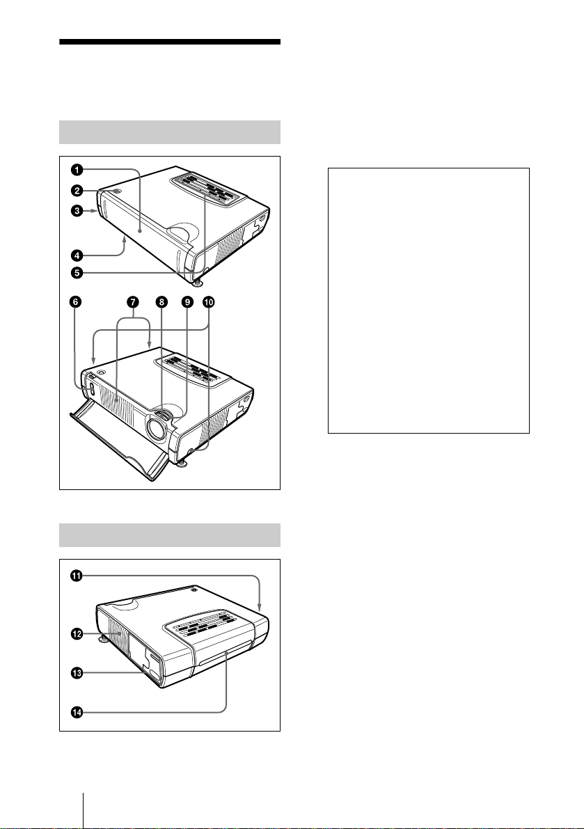
1 Front cover
Press the OPEN button to open the front
cover.
2 OPEN button
Front/Side/Bottom
Rear/Left Side
3 Security lock (right side)
Connects to an optional security cable
(Kensington’s).
The security lock corresponds to
Kensington’s MicroSaver
System.
If you require further information,
contact
Kensington
2855 Campus Drive
San Mateo, CA 94403
in North America
Phone: 800-235 -6708
Fax: 800-247-1317
Outside North America
Phone: 847-541 -9500
Home page address:
http://www.kensington.com/
®
Security
4 Lamp cover (bottom)
5 Control panel
For details, see “Control Panel” on
page 10.
6 Front remote control detector
(SIRCS receiver)
GB
Location and Function of Controls
8
7 Ventilation holes (exhaust)
8 Focus lever
Adjusts the picture focus.
9 Zoom lever
Adjusts the picture size.
q;
q; Adjuster adjustment buttons
q;q;
For details,see “How to use the
adjuster” on pag e 9.
qa
qa Speaker
qaqa
qs Ventilation holes (intake)
Notes
• Do not place anything near the
ventilation holes as it may cause in ternal
heat build-up.
• Do not place your hand or objects near
the ventilation holes as it may cause the
air coming out heat build-up.
qd Connector panel
For details, see “Connector Panel” on
page 11.
qf Rear remote control detector
(SIRCS receiver)
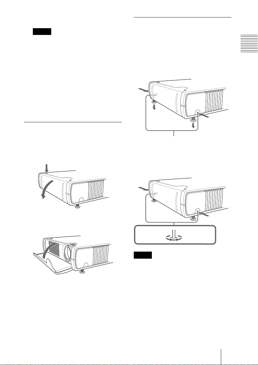
How to open/close the front cover
How to use the adjuster
To adjust the height
Adjust the height of the proje ctor as follows:
1 Lift the projector and press the
adjuster adjustment buttons.
The adjusters will extend from the
projector.
Overview
To open the front cover
Press the OPEN button.
The front cover is opened and set on the
front of the project or.
To close the front cover
Restore the front cover by hand.
• Do not tilt the projector ou t of the range of
the adjuster setting when you open the
front cover. If the projector is tilted too
much, the front cover opens speedily or
slowly.
• The lamp goes o ut if the front cover is kept
closed while the power is on.
Adjuster adjustment buttons
2 While pressing the buttons, lower the
projector. Then, release the buttons.
For fine adjustment, turn the adjusters
to the right and the left.
to lower the
projector
Notes
• Be careful not to let the projector down
on your fingers.
• Do not push hard on the top of the
projector with the adjusters out.
It may be occurred malfunction.
to raise the
projector
Location and Function of Controls
GB
9
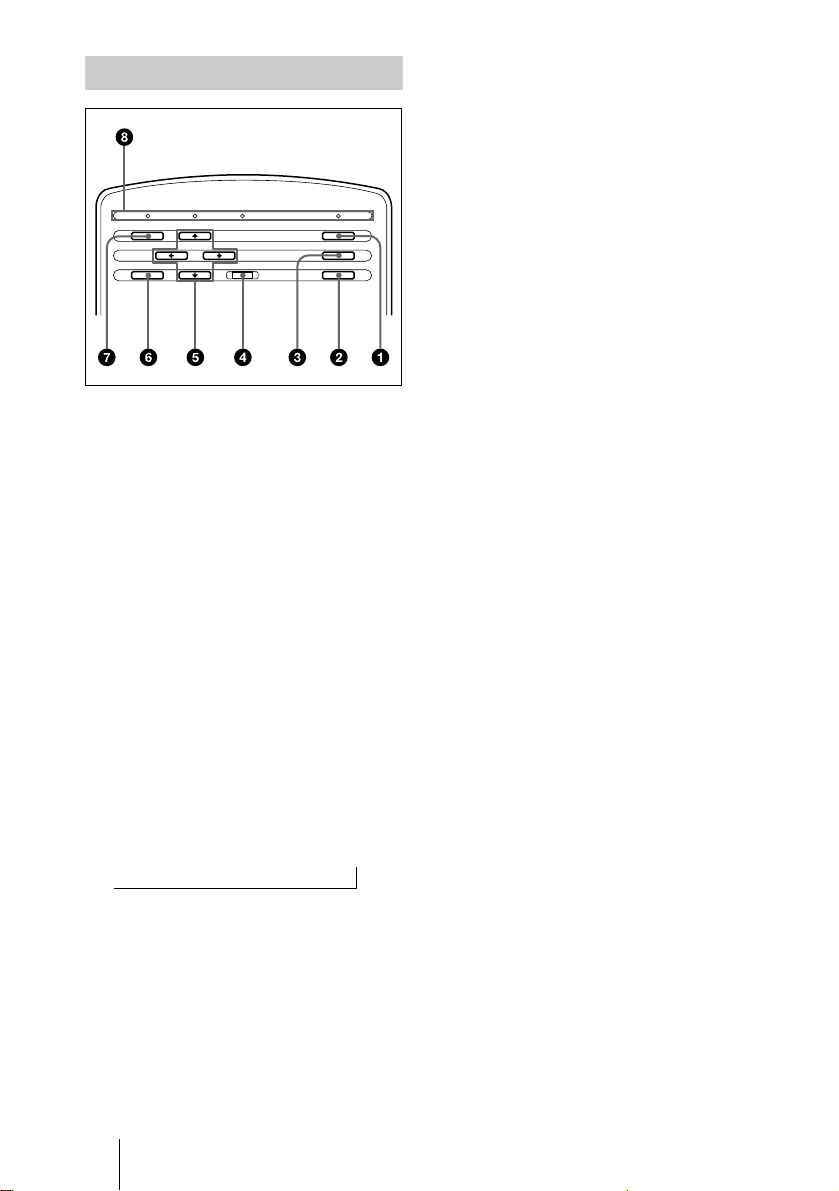
Control Panel
LAMP/COVER
MENU POWER
1 I / 1111 (on/standby) key
Turns on and off the projector when the
projector is in standby mode. The ON/
STANDBY indicator lights in green
when the power is turned on.
When turning off the power, press
the I / 1 key twice followin g the
message on the screen, or press and hold
the key for about on e sec ond.
For details on steps for turning off the
power, see “To turn off the power” on
page 23.
2 APA (Auto Pixel Alignment) key
Adjusts a picture clearest automatically
while a signal is input from a computer.
3 INPUT key
Selects the input signal. Each time you
press the key, the input signal switches
as follows:
INPUT AtINPUT BtMStVIDEOtS VIDEO
t
4 RESET key
Resets the value of an item back to its
factory preset value. This key functions
when the menu or a setting item is
displayed on the screen.
5 Arrow keys (MMMM/mmmm/<<<</,,,,)
Select the menu or to make various
adjustments.
POWERSAVING ON/STANDBY
TEMP/FAN
INPUT
APARESETENTER
6 ENTER key
Enters the settings of items in the menu
system.
7 MENU key
Displays the on-screen menu. Press
again to clear t he me nu.
8 Indicators
• LAMP/COVER: Lights up or flashes
under the following conditions:
– Lights up when the lamp has
reached the end of its life or
becomes a high temperature.
– Flashes when the lamp cover is not
secured firmly or the front cover is
kept closed and the lam p goe s out.
• TEMP (Temperature)/FAN: Lights
up or flashes under the following
conditions:
– Lights up when temperature inside
the projector becomes unusually
high.
– Flashes when the fan is broken.
• POWER SAVING: Lights up when
the projector is in power savi ng mode.
When POWER SAVING in the SET
SETTING menu is set to ON, the
projector goes into power saving mode
if no signal is input for 10 minutes.
Although the lamp goes out, the
cooling fan keeps running. In power
saving mode, no keys function for the
first 60 seconds. The power saving
mode is canceled when a signal is
input or any key is pressed.
• ON/STANDBY: Lights up or f lashes
under the following conditions:
– Lights in red when a AC power cord
is plugged into a wall o utlet. Once in
standby mode, you can turn on the
projector with the I / 1 key.
– Lights in green when the power is
turned on.
– Flashes in green while the cooling
fan runs after the power is turned off
with the I / 1 key. The fan runs for
about 90 seconds after the power is
turned off.
The ON/STANDBY indicator
flashes quickly for the first 60
seconds. During this time, you
GB
Location and Function of Controls
10

cannot light up the ON/STANDBY
indicator w ith the I / 1 key.
For details on the LAMP/COVER and
the TEMP/FAN indicators, see on
pages 34, 35.
Connector Panel
Left side
~AC IN
INPUT A
S VIDEOVIDEOAUDIO
INPUT A
~AC IN
INPUT B
4 INPUT B connector (RGB (DVI))
(DVI-D)
Connect to a equipment equipped with
DVI (digital) output connector with a
DVI cable.
5 INPUT A connector (HD D-sub
15-pin, female)
Connect to external equipment such as a
computer.
Connects to the monitor output on a
computer using the su pp lie d ca b le .
When inputting a component or 15k
RGB signal, use an optional cable.
6 USB connector (USB plug for
upstream, 4-pin)
Connect to the USB connector on a
computer. When you connect the
projector to the computer, you can
control the mouse function with the
supplied Remote Commander. The
supplied application software can be
installed in the computer attached to this
connector.
Overview
1 Memory Stick slot
The Memory Stick can be attached.
Never insert an object other than the
Memory Stick.
For details, see the attached “Operating
Instructions for Memory Stick”.
2 Video input connector
Connect to external video equipment
such as a VCR.
• VIDEO (phono type): Connects to
the composite vi deo output of vide o
equipment.
• S VIDEO (mini DIN 4-pin):
Connects to the S video output (Y/C
video output) of video equipment.
3 AUDIO (stereo minijack)
connector
When listening to soun d output fro m the
computer, connect to the audio output of
the computer.
When listening to soun d output fro m the
VCR, connect to the audio output of the
VCR.
7 AC IN socket
Connects the supplied AC power cord.
8 Access lamp
Lights during havin g access to the
Memory Stick.
Do not remove the Memory S tick while
the access lamp is lit.
Location and Function of Controls
11
GB

Remote Commander
The keys that have the same names as those
on the control panel function identically.
You can control a connected computer using
the Remote Commander.
For details, see “To control the computer
using the supplied Remote Co mmand er” on
page 22.
qh
qg
qf
qd
qs
qa
0
9
8
FREEZE
INPUT
MENU ENTER
+
–
D ZOOM
12
MS SLIDE
D KEYSTONE
RESET
FUNCTION
I / 1
APA
R
CLICK
1
2
3
4
5
6
7
6 R CLICK key
Functions as the right butto n on a mouse.
7 FUNCTION 1, 2 keys
These keys function when th e supplied
application software is used.
When you connect the projector with a
computer, you can open a file on the
screen by just pressing the FUNCTION
key. This will enhance your
presentation. To use this function,
allocate a file to the FUNCTION ke y by
using the application software.
For details, see the README file and
the HELP file supplied with the
application softwa re .
8 RESET key
Resets the value of an item back to its
factory preset value or returns the
enlarged image back to its original size.
9 D ZOOM +/– key
Enlarges the image at a desired location
on the screen.
+:Pressing the + key on ce displays the
icon. This icon indicates the point yo u
want to enlarge. Use an arrow key (M/
m/</,) to move the icon to the
point to be enlarged. Press the + key
repeatedly until the image is en larged
to your requirements.
–: Pressing the – key reduces an image
that has been enlarged with the D
ZOOM + key.
q; L CLICK key
Functions as the left button on a mouse.
qa MENU key
1
I / 1111
key
2 APA (Auto Pixel Alignment) key
3 ENTER key
4 Joystick
Functions as the mouse of the computer
connected to the unit.
5 Arrow keys (MMMM/mmmm/<<<</,,,,)
GB
Location and Function of Controls
12
qs D KEYSTONE key
Adjusts trapezoidal distortion of the
picture that may occur depending on the
projector angle. Use an arrow key (M/m/
</,) to square the image.
qd INPUT key
qf FREEZE key
Used to freeze the picture project ed. To
cancel the frozen pictu re, press the key
again.
qg MS SLIDE key
Used to execute the slide show. The
input signal switches to MS and the slide
show begins.
qh Infrared transmitter
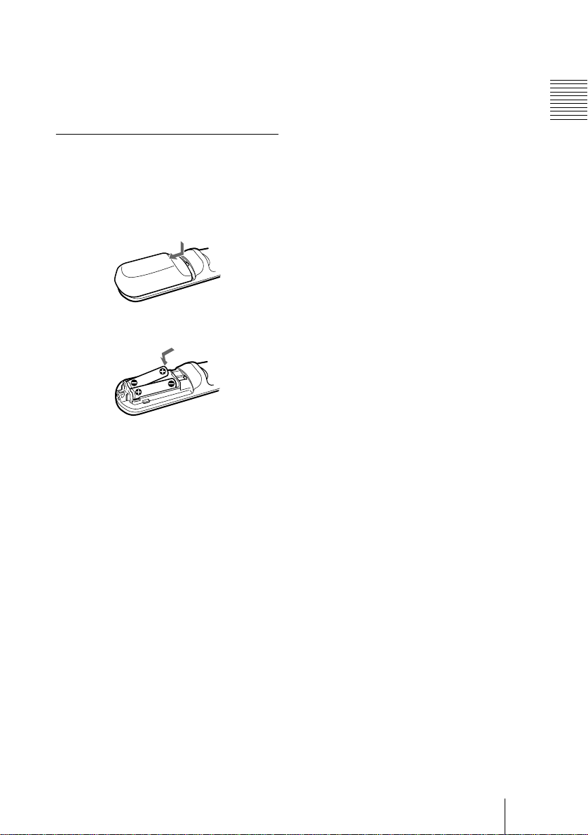
To install batteries
Push and slide to op e n the lid, the n
1
install the two size AA (R6) ba tte rie s
(supplied ) with the cor r e c t p olarity.
While pressing the lid, slide it.
the angle within which the commander can
control the projector becom es.
Overview
Be sure to install the battery
from the
Replace the lid.
2
Notes on batteries
• Mak e sure tha t the batte ry orien tation is
correc t when inserting batteries.
• Do not mix an old b attery w ith a new on e or
differen t types of batteries.
• If you do not us e the Remote Comma nder for
a long time, remove the batteries to avoid
damage from battery leakage. If batteries
have leaked, remove them, wipe and dry the
battery compartmen t, an d replace the
batteries with new ones.
Notes on Remote Commander
operation
• Make sure that nothing obstructs the
infrared beam between the Remote
Commander and the remote control
detector on the projector. Direct the
Remote Commander toward the front or
rear remote control detector.
• The operation range is limited . The shorter
the distance between the Remote
Commander and the projector is, the wider
#
side.
Location and Function of Controls
13
GB
Setting Up and Projecting
B
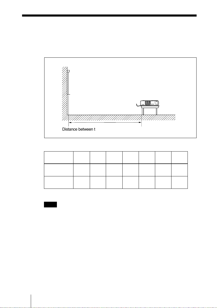
Installing the Projector
This section describes ho w to install the projector.
The distance between the lens and the screen varies depending on the size of
the screen. Use the following table as a guide.
Distance between the screen and the center of the lens
Unit: m (fee t)
Screen size
(inches)
Minimum
Distance
Maximum
Distance
40 60 80 100 120 150 200
1.5
(4.9)
1.9
(6.2)
2.3
(7.5)
2.8
(9.1)
3.1
(10.1)
3.7
(12.1)
3.9
(12.7)
4.7
(15.4)
4.7
(15.4)
5.6
(18.3)
5.9
(19.3)
7.1
(23.2)
7.9
(25.9)
9.4
(30.8)
GB
Note
You can not install the projector upside down, such as on a ceiling.
Installing the Projector
14
(Tolerance of measurement is ±5 %.)

Connecting the Projector
To connect the projector, refer to the illustrations on the next and the
following pages.
• Turn off all equipmen t before making any connections.
• Use the proper cables for each connection.
• Insert the cable p lugs properly ; plugs that are not fully inse r ted often
generate no ise. Whe n pulling o ut a cable, be sure to pull it ou t from the p lug,
not the ca ble itse lf .
Connecting with a Computer
This section describes how to connect the projector to a computer.
For mor e informatio n, refer to the c omputer’s instruction manual.
Notes
• The projector accepts VGA, SVGA, XGA, and SXGA signals. However, we
recommend that you set the output mode of your computer to XGA mode for the
external monitor.
• If you set your computer, such as a notebook type, to output the signal to both your
computer’s display and the ex tern al mo nitor, the p icture o f the extern al m onito r may
not appear properly. Set your computer to output the signal to only the external
monitor.
For deta i ls, refer to the compu ter ’s operating instructions supplied with your
computer.
• This p rojector is compatible with a DDC2 B (Digital Dat a Channel 2B). If you r
comp uter is co m p atibl e w ith a D DC , tu rn the pro jec tor o n a cco rdin g to th e fo llow in g
procedures.
1 Connect the projector to the computer by using the supplied HD D-sub 15 pin cable.
2 Turn the projector on.
3 Start the computer.
Setting Up and Projecting
Connecting the Projector
15
GB
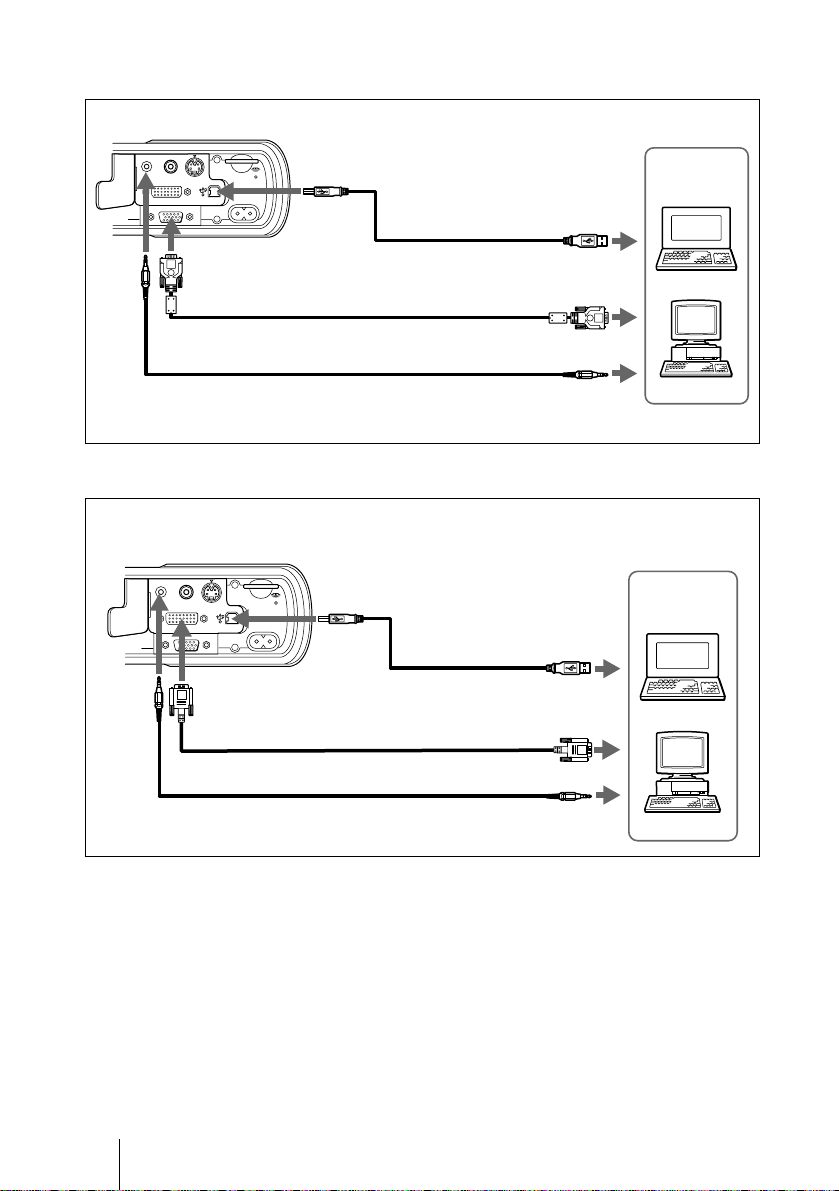
To connect an IBM PC/AT compatible computer
Left side
S VIDEOVIDEOAUDIO
INPUT A
~AC IN
USB cable*
(supplied)
INPUT B
HD D-sub 15-pin cable (supplied)
Audio connecting cable (not supplied)
To connect a DVI compatible equipment
Left side
S VIDEOVIDEOAUDIO
INPUT A
~AC IN
USB cable*
INPUT B
(supplied)
DVI cable SMF-421 (not supplied)
24 pins (male) (DVI ↔ DVI)
Computer
to USB connector
to monitor output
to audio output
Computer
to USB connector
to DVI output
GB
* When you want to use the wireless mouse function and the supplied application
software (Projector Station), connect your computer with the supplied USB cable.
Connecting the Projector
16
Audio connecting cable (not supplied)
to audio output

On the USB function
When connecting the projector to a computer by using the USB cable for the
first time, the c ompute r r ec ognizes th e f ollowing devices automatically.
1 USB hub (general use)
2 USB human interface device (wireless mouse function)
3 USB human in te r fac e device (pro je c tor control fu n c tion)
Recommended operating environment
When y ou use the USB function , connec t your com puter as illustrated o n page
16. This application software and the USB function can be used on a compu ter
loaded with Windows 98, Windows 98 SE, Windows ME or Windows 2000
preinstall m odels.
Notes
• Your computer may not start correctly when connected to the projector
via the USB cable. In this case, disconnect the USB cable, restart the
computer, then connect the computer to the projector using the USB
cable.
• This projector is not guaranteed for suspend, standby mode. When you
use the projector in suspend, standby mode, disconnect the projector
from the USB port on the computer.
• Operations are not guaranteed for all the recommended computer
environments.
To connect a Macintosh computer
To connect a Macintosh computer equipped with video output connector of a
type having two rows of pins, use a com m ercially available plug adaptor.
However, you can not control the mouse of the computer by the Remote
Commander.
Setting Up and Projecting
Connecting with a VCR or 15k RGB/Component Equipment
This section describes how to connect the projector to a VCR and 15k RG B /
component equipment.
For mor e information, refer to the instruction manuals of the equipment you
are connecting.
Connecting the Projector
17
GB
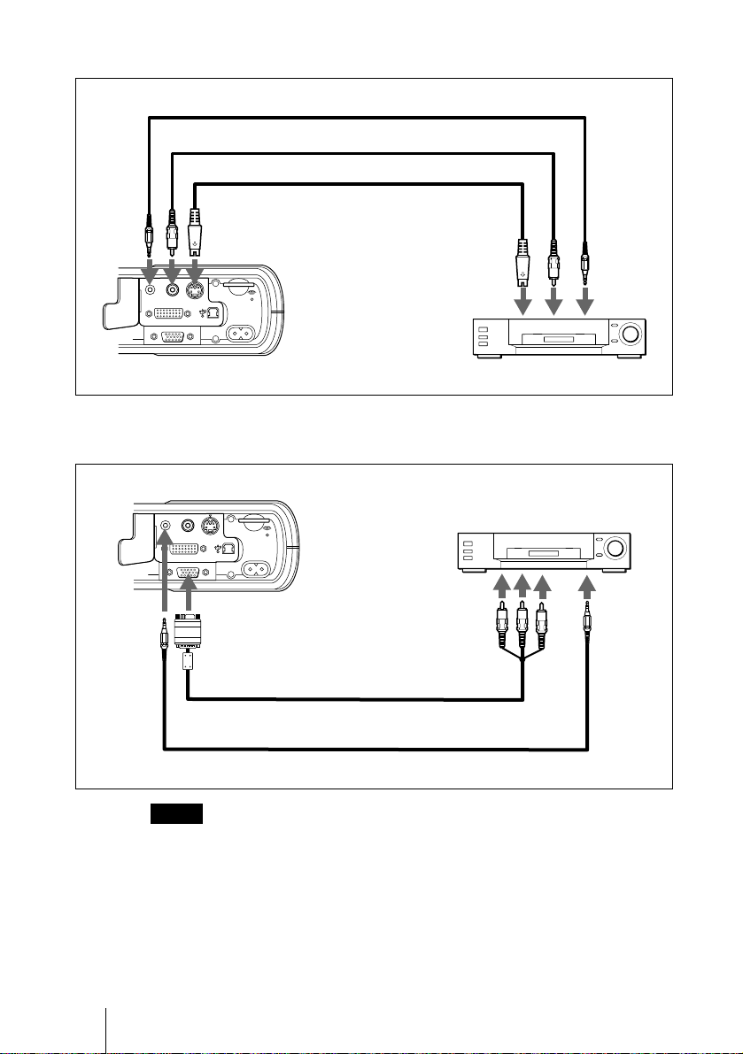
To connect a VCR
Audio connecting cable (not supplied)
Video cable (not supplied)
S-Video cable (not supplied)
Left side
S VIDEOVIDEOAUDIO
INPUT A
~AC IN
INPUT B
To connect a 15k RGB/Component equipment
Left side
S VIDEOVIDEOAUDIO
INPUT A
~AC IN
INPUT B
to video output
to S video
output
VCR
15k RGB/Component equipment
to RGB/
component
output
to audio
output
to audio
output
GB
Notes
et the aspect ratio using ASPECT in the INPUT SETTING menu
• S
according to the input signal.
• When
select video GBR or component with the INPUT-A setting in the SET
SETTING menu.
se the composite sync signal when you input the external sync signal
• U
from 15k RGB/component equipment.
Connecting the Projector
18
SMF-402 Signal Cable (not supplied)
HD D-sub 15-pin (male) ↔ 3 × phono jack
Audio connecting cable (not supplied)
you connect the unit to 15k RGB or component video equipment,
Selecting the Menu Language
You can select one of nine languages for d isplaying the m e nu and oth er onscreen disp lays. The fac tory setting is E nglish.
Front remote
control detector
I / 1
MS SLIDE
FREEZE
D KEYSTONE
INPUT
MENU ENTER
APA
TEMP/FAN
LAMP/COVER
MENU POWER
POWERSAVING ON/STANDBY
Setting Up and Projecting
INPUT
APARESETENTER
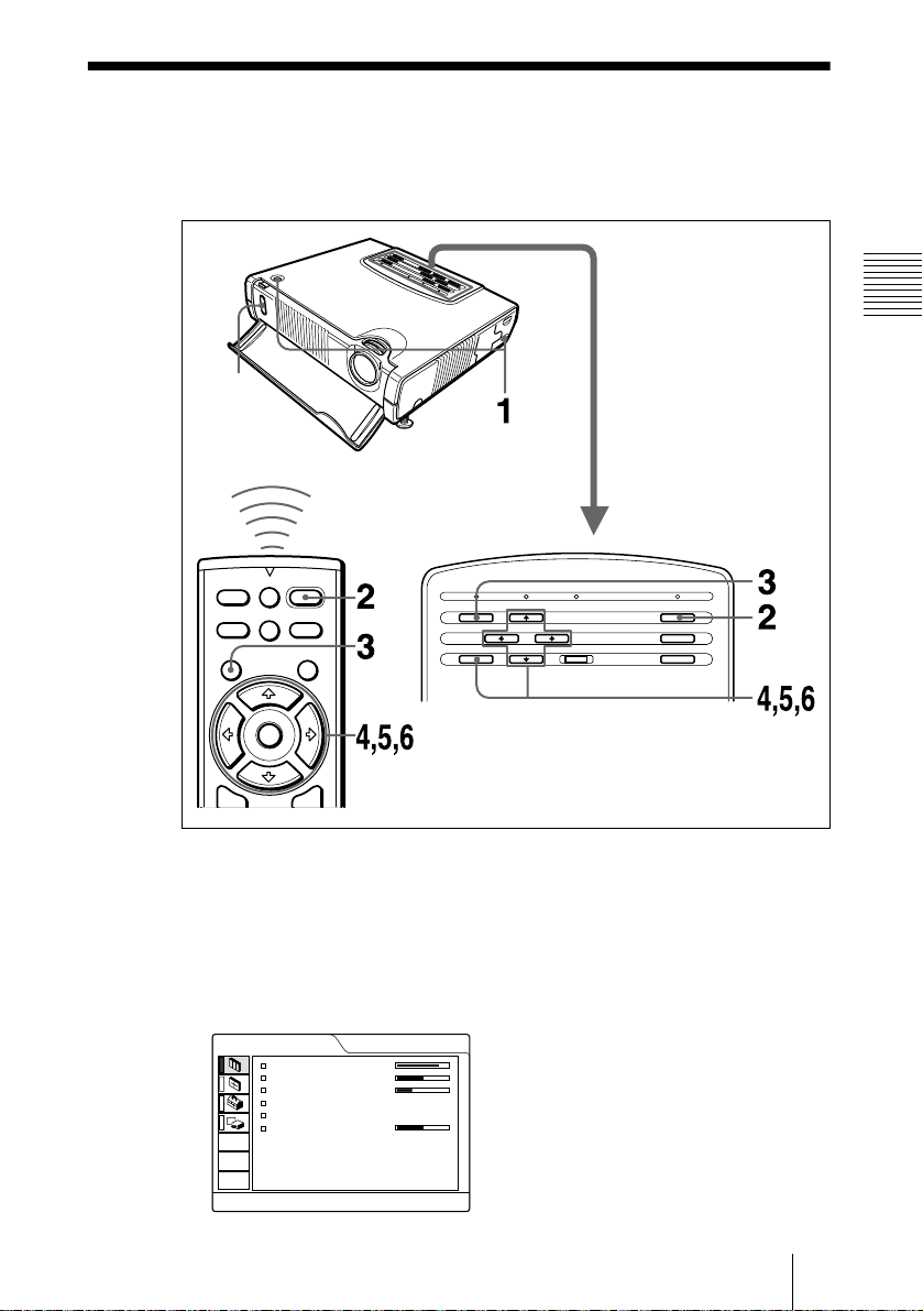
1
Plug the AC power cord into a wall o utlet, then open the fro n t cover.
2
Press the I / 1 key to turn on the projector.
3
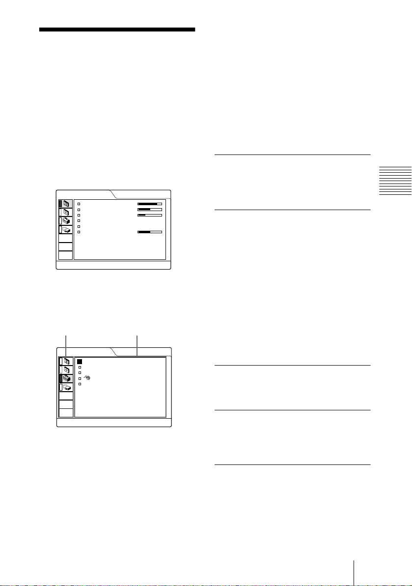
Press the M E NU key.
The menu appears.
The menu presently selected is shown as a yellow button.
PICTURE CTRL
CONTRAST:
BRIGHT:
RGB ENHANCER
GAMMA MODE:
COLOR TEMP:
VOLUME:
:
80
50
30
GRAPHICS
HIGH
50
INPUT-A
Selecting the Menu Language
19
GB
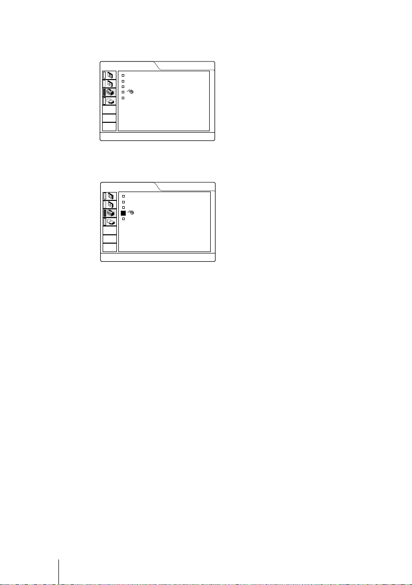
4
Press the M or m key to select the SET SETTING menu, then press the ,
or ENTER key.
The selected menu appears.
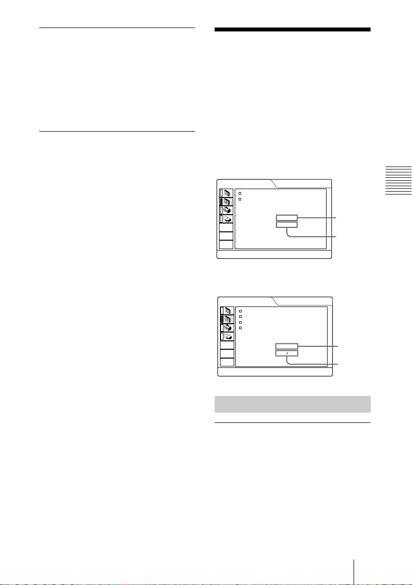
SET SETTING
STATUS:
INPUT-A:
AUTO INPUT SEL
POWER SAVING
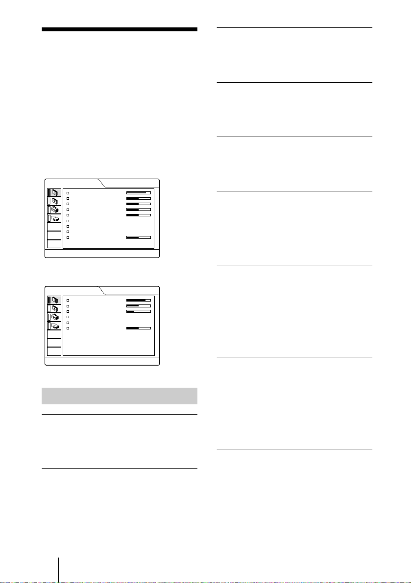
5
Press the M or m key to select “LANGUAGE,” then press the , or
LANGUAGE
ON
COMPUTER
:
OFF
:
ENGLISH
:
OFF
INPUT-A
ENTER key.
SET SETTING
STATUS:
INPUT-A:
AUTO INPUT SEL
POWER SAVING
6
Press the M or m key to se le c t a la nguage, then pres s the < or ENTER
LANGUAGE
ON
COMPUTER
:
OFF
:
ENGLISH
:
OFF
INPUT-A
key.
The menu changes to the selected language.
To clear the menu
Press the MENU key.
The menu disappe a rs a uto matically if a key is not pr e sse d for one m inute.
GB
Selecting the Menu Language
20
Projecting
I / 1
MS SLIDE
FREEZE
D KEYSTONE
INPUT
MENU ENTER
APA
Rear remote control
detector
LAMP/COVER
TEMP/FAN
MENU POWER
POWERSAVING ON/STANDBY
Setting Up and Projecting
ON/STANDBY
indicators
INPUT
APARESETENTER
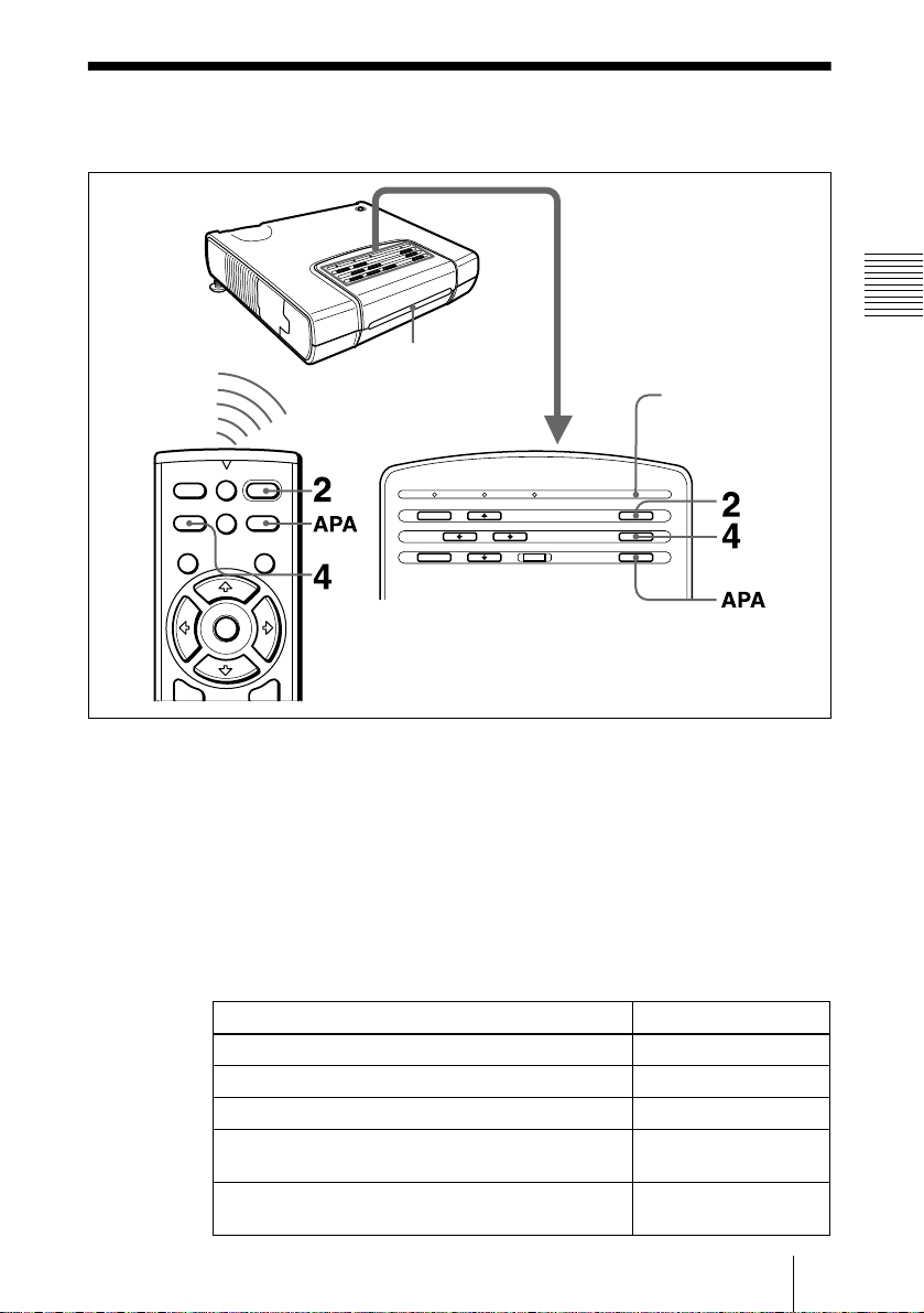
1
Plug the A C pow er cord into a wall o utlet, and connec t all equipm ent, the n
open the front cover.
The ON/STAN DBY indicator lights in red and the projector goes into
standby mode.
2
Press the I / 1 key.
The ON/STAND BY indicator lights in green.
3
Turn on the equipment connected to the projector.
4
Press the IN PUT ke y to select the in put source.
To inp u t from Press INPUT to displ a y
Computer c onnecte d to the INPUT A co n nector INPU T A
Computer connected to the INPUT B connector INPUT B
Memory Stick inserted to th e Memoty Stick slot MS
V ideo equipment connected to the VIDEO input
connector
V ideo equipment connected to the S VIDEO input
connector
VIDEO
S VIDEO
Projecting
21
GB
5
Turn the zoom lever to adjust the size of the picture.
6
Turn the f ocus lever to a djust the focu s.
Attention
Looking into the lens when projecting may cause injury to your eyes.
To adjust the volume
The volume can be adjusted in the on-screen menu. See “VOLUME” in the
PICTURE C T RL menu on pag e 27 .
To control the computer using the supplied Remote Commander
When you connect an IBM PC /A T co m patible to the projector by using the
USB cable, you can control the mouse of the com pu ter using the Rem o te
Commander.
The R/L CLICK keys and joystick fun c tion as follows.
Key and joystick Function
R CLICK (front) Right button
L CLI CK (rea r) Left button
Joystick Corresponds with the mov e ments of the mo us e
Note
Make sure that nothing o bstructs t he infrared beam between the Remo te Com mander
and the remoter control detector on the projector.
To get the clearest picture
You can adjust pictur e q uality whe n projecting a signal from the computer.
GB
22
1
Project a still picture fro m the computer.
2
Press the APA key.
“Com p le te !” appears on the screen when the picture is adjusted properly.
Notes
• Press the APA key when the full image is displayed on the screen. If there are black
edges around the image, the APA function will not function properly and the image
may extend beyond the screen.
• When you switch the input signal or re-connect a computer, press the APA key again
to adjust the picture again.
• You can cancel the adjustment by pressing the APA key again while “ADJUSTING”
appears on the screen.
• The picture may not be adjusted prope rly depe ndin g on the kind s of input signa ls.
• Adjust the items in the INPUT SETTING menu when you adjust the picture manually.
Projecting

To turn off the power
Press the I / 1 key.
1
“POWER OFF? Please press I / 1 key again.” app ears to confirm that you
want to turn off the power.
Note
A mess ag e dis ap pears if you pres s any key exce p t th e I / 1 key, or if you do not
press any key for five seconds.
Press the I / 1 key again.
2
The ON/STANDBY indicator flashes in green and the fan continues to run for
about 90 seconds to reduce the internal heat. Also, the ON/STANDBY
indicator flashes quickly for the first 60 secon ds. During this time, you will not
be able to light up the ON/STANDBY indicator with the I / 1 key.
Unplug th e A C pow e r cord from th e wall outlet a nd close the fr o nt cover
3
after the fan stops running and the ON/STANDBY indicator lights in red.
When you cannot confirm the on-screen message
When you cannot confirm the on-screen message in a certain condition, you can
turn off the power by holding the I / 1 key for about one second.
Notes
• Do not unplug the AC power cord while the fan is still running; otherwise, the fan
will stop even thou gh the interna l heat is still high, w hich cou ld result in a breakdow n
of the projector.
• Do not cl os e the fron t c o v er while th e f a n is runn in g ; otherwis e , the inter nal heat
does not drop, which could result in a breakdown of the projector.
Setting Up and Projecting
Projecting
23
GB
Effective Tools for Your Presentation
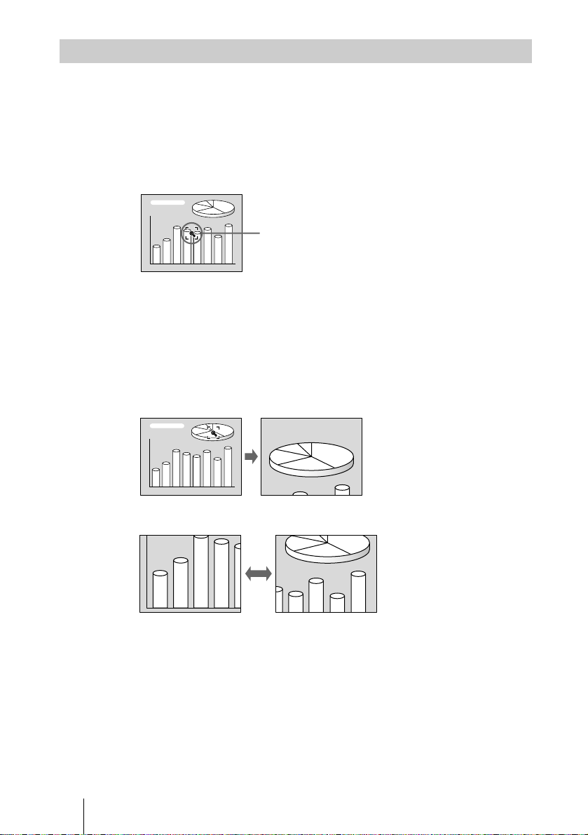
To enlarge the image (Digital Zoom function)
You can se le ct a point in th e image to e nla r g e . This functio n works wh e n a
signal from a computer is input and the picture saved in the Memory Stick is
projected.
Press the D ZOOM + k e y o n the Remote Commander.
1
The digital zoom icon appears the center of the image.
Digital zoom icon
Move th e icon to the point on the image yo u want to enlarge. U se the arrow
2
key (M/m/</,) to move the icon.
Press the D ZOOM + k ey ag ain.
3
The image where the icon is located is enlarged. The enlargement ratio is
displayed on the scr e e n f or a f e w s ec o nd s .
By pressing the + key repeatedly, the image size increases (ratio of
enlargement: max. 4 times.)
Use the arrow key (M/m/</,) to scroll the enlarged image.
To return the image back to its original size
Press the D ZOOM – key.
Just pressing the RESET key retu rns the imag e back to its or iginal size
immediately.
To freeze the image projected (Freeze function)
Press the FREEZE key. “FREEZE” appears when the key is pressed. Th is
function works when a signal from a computer is input and the picture saved
in the Memory Stick is projected.
To restore the original screen, press the FREEZE key again.
GB
Projecting
24
Adjustments and Settings Using the Menu
B
• When changing the adjustmen t level:
Using the MENU
To increase the number, press the
,
To decrease the number, press the m
The projector is equipped with an on-screen
menu for making various adjustments and
settings. You can change the men u language
displayed in the on-sc r e e n menu.
To change the menu language, see
“Selecting the M enu Lang uage” on page 19.
1
Press the MENU key.
The menu appears.
The menu presently selected is shown as
a yellow button.
PICTURE CTRL
CONTRAST:
BRIGHT:
RGB ENHANCER
GAMMA MODE:
COLOR TEMP:
VOLUME:
:
80
50
30
GRAPHICS
HIGH
50
INPUT-A
or < key.
Press the ENTER key to restore the
original screen.
• When changing the setting:
Press the M or m key to change the
setting.
Press the ENTER or < key to restore
the original screen.
To clear the menu
Press the MENU key.
The menu disappears automatically if a key
is not pressed for one minute.
To reset items that have been
adjusted
Press the RESET key.
“Complete!” appears on the screen and the
settings appearing on the screen are reset
to their factory preset values.
Items that can be reset are:
2
Use the M or m key to select a menu,
then pres s the , or ENTER key.
The selected menu appears.
Menus
Setting items
•“CONTRAST,” “BRIGHT,” “COLOR,”
“HUE,” “SHARP”, and “RGB
ENHANCER” in the PICTURE CTRL
menu
•“DOT PHASE,” “SIZE H,” and “SHIFT”
in the INPUT SETTING menu
•“DIGIT KEYSTONE” in the INSTALL
SET SETTING
STATUS:
INPUT-A:
AUTO INPUT SEL
LANGUAGE
POWER SAVING
:
ON
COMPUTER
:
OFF
:
ENGLISH
OFF
INPUT-A
SETTING menu.
About the memory of the settings
The settings are automatically stored in the
projector memory.
key.
or
M
Adjustments and Settings Using the Menu
3
Select an item.
Use the M or m key to selec t the item ,
then pres s the , or ENTER key.
4
Make the setting or a d justment on a n
item.
If no signal is input
If there is no input signal, “NO INPU T –
Cannot adjust this item.” appears on the
screen.
About the menu display
You can set the display positio n of the menu,
intensity of the background picture and tone
of the menu items as you like.
For details, see page 30.
Using the MENU
25
GB
The PICTURE CTRL
Menu
COLOR
Adjusts color intensity. The higher the
setting, the greater the intensity. The lower
the setting, the lower the intensity.
The PICTURE CTRL (control) menu is used
for adjusting the picture.
Items that cannot be ad justed depending on
the input signal are not displayed in the
menu.
For details on the unadjustable items, see
page 40.
When the video signal is input
PICTURE CTRL
CONTRAST:
BRIGHT:
COLOR:
HUE:
SHARP:
D. PICTURE:
COLOR TEMP:
COLOR SYS:
VOLUME:
80
50
50
50
50
OFF
LOW
AUTO
50
VIDEO
When the RGB signal is input
PICTURE CTRL
CONTRAST:
BRIGHT:
RGB ENHANCER
GAMMA MODE:
COLOR TEMP:
VOLUME:
:
80
50
30
GRAPHICS
HIGH
50
INPUT-A
Menu Items
CONTRAST
Adjusts the picture contrast. The hi gher the
setting, the greater the contrast. The lower
the setting, the lower the contrast.
BRIGHT
Adjusts the picture brightness. The higher
the setting, the brighter the picture. The
lower the setting, the darker the picture.
HUE
Adjusts color tones. The higher the setting,
the picture becomes greenish. The lower the
setting, the picture beco mes purplish.
SHARP
Adjusts the picture sharpness. The higher the
setting, the sharper the picture. The lower
the setting, the softer the picture.
RGB ENHANCER
Adjusts the picture sharpness when RGB
signals are input.
The higher the setting, the sharper the
picture. The lower the setting, the softer the
picture.
D. (Dynamic) PICTURE
Emphasizes the black color.
ON: Emphasizes the black color to produce
a bolder “dynamic” picture.
OFF: Reproduces the dark portions of the
picture accurately, in accordance with
the source signal.
GAMMA MODE
Selects a gamma correction curve .
GRAPHICS: Improves th e re pr oduc tion of
halftones. Phot os can be reproduced in
natural tones.
TEXT: Contrasts black and white. Suitable
for images that contain lots of text.
COLOR TEMP
Adjusts the color temperature.
HIGH: Makes the white color bluish.
LOW: Makes the white color r e ddish.
GB
The PICTURE CTRL Menu
26
COLOR SYS (System)
Selects the color system of the input signal.
• AUTO: NTSC
NTSC
• PAL-M/N: PAL-M/PAL-N and NTSC
(switched automatically)
Normally, set to AUTO. If the picture is
distorted or colorless, select the color system
according to the input s ig nal.
3.58
4.43
, PAL, SECAM and
(switched automatically)
3.58
VOLUME
Adjusts the volume. The volume can be
adjusted for each of INPUT A, INPUT B,
MS, VIDEO and S VIDEO input.
The INPUT SETTING
Menu
The INPUT S ETTING menu is used to
adjust the input signal.
Items that cannot be adjusted depending on
the input signal are not displayed in the
menu.
For details on the unadjustable items, see
page 40.
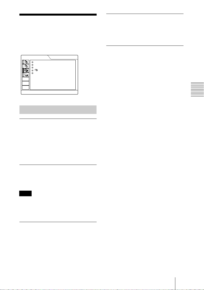
When the video signal is input
INPUT SETTING
SHIFT:
ASPECT:
H: 200 V: 30
4:3
VIDEO
Adjustments and Settings Using the Menu
No. 01
VIDEO/60
Memory
No.
Signal
type
When the RGB signal is input
INPUT SETTING
DOT PHASE:
SIZE H:
SHIFT:
SCAN CONV:
15
800
H: 200 V: 30
ON
No. 13
640 480
INPUT-A
Memory
No.
Signal
type
MENU Items
DOT PHASE
Adjusts the dot phase of the DMD
and the signal input fr om the INPU T A
connector.
Adjust the picture further for finer picture
after the picture is adjusted by pressi ng the
APA key.
Adjust the picture to where it look s clea rest.
TM
panel
The INPUT SETTING Menu
27
GB

SIZE H
Adjusts the horizontal size of picture input
from the INPUT A connector. The higher
the setting, the larger the horizontal size of
the picture. The lower the setting, the
smaller the horizontal size of the pi cture.
Adjust the setting according to the dots of
the input signal.
For details on the suitable value for the
preset signals, see page 41.
SHIFT
Adjusts the position of the pic ture. H adjusts
the horizontal posi tion of the picture.V
adjusts the vertical position of the picture.
As the setting for H increases, the picture
moves to the right, and as the setting
decreases, the picture moves to the left.
As the setting for V increases, the picture
moves up, and as the setting decreases, the
picture moves down. Use the < or the ,
key to adjust the horizontal position and the
M and m key for the vertical position.
SCAN CONV (Scan converter)
Converts the signal to display the picture
according to the screen size.
ON: Displays the pic ture according to the
screen size. The picture will lose some
clarity.
OFF: Displays the picture while matching
one pixel of input picture element to that
of the DMD
but the picture size will be smaller.
Note
When XGA or SXGA signal is input, this item
will not be displayed.
TM
. The picture will be clear
ASPECT
Sets the aspect ratio of the picture. Wh en
inputting 16:9 (squeezed) signa l from
equipment such as a DVD player, set to
16:9.
4:3: Wh en the picture with ratio 4:3 is inpu t.
16:9: When the picture with ratio 16:9
(squeezed) is input.
About the Preset Memory No.
This projector has 37 ty pes of p reset da ta for
input signals (the preset memory). When a
preset signal is input, t he projector
automatically detects the signal type and
recalls the data for the signal from the preset
memory to adjust it to an optimum picture.
The memory number and signal type of that
signal are displayed in the INPUT
SETTING menu. You can also adjust the
preset data through the INPUT SETTING
menu.
This projector has 20 types of user memories
for INPUT-A into which you can save the
setting of the adjusted data for an unpreset
input signal.
When an unpreset signal is input for the first
time, a memory number is displayed as 0.
When you adjust the d ata of the signa l in the
INPUT SETTING menu, it will be
registered to the projector. If more than 20
user memories are registered, the newest
memory always overwrites the ol dest one.
See the chart on page 4 1 to find if the si gnal
is registered to the preset memory.
Since the data is recalled from the preset
memory about the following signals, you
can use these preset data by adjusting SIZE
H. Make fine adjustment by adjusting
SHIFT.
Signal Memory No. SIZE
Super Mac-2 23 1312
SGI-1 23 1320
Macintosh 19" 25 1328
Macintosh 21" 27 1456
Sony News 36 1708
PC-9821
1280 × 1024
WS Sunmicro 37 1664
Note
When the aspect ratio of input signal is other
than 4:3, a part of the screen is displayed in
black.
36 1600
GB
The INPUT SETTING Menu
28
The SET SETTING
Menu
The SET SETTING menu is used for
changing the settings of the projector.
SET SETTING
STATUS:
INPUT-A:
AUTO INPUT SEL
LANGUAGE
POWER SAVING
ON
COMPUTER
:
OFF
:
ENGLISH
:
OFF
Menu Items
STATUS (on-screen display)
Sets up the on-s creen display.
ON: Shows all of the on-screen displays.
OFF: Turns off the on-screen displays
except for the menus, a message when
turning off the power, and warning
messages.
INPUT-A
LANGUAGE
Selects the language used in the menu and
on-screen displays. Available languages are:
English, French, German, Italian, Spanish,
Portugueses, Japanese, Chinese and Korean.
POWER SAVING
When set to ON, the projector goes into
power saving mode if no signal is input for
10 minutes.
Adjustments and Settings Using the Menu
INPUT-A
Selects the comp uter, component or vide o
GBR signal input from the INPUT A
connector.
Note
If the setting is not co rr ec t, “Please check
INPUT -A setting .” appears on the screen and
the color of the pictur e be comes strange or th e
picture is not displayed.
AUTO INPUT SEL
When set to ON, the projector detects input
signals in the following order: INPUT-A/
INPUT B/MS/VIDEO/S-VIDEO. It
indicates the input channel when the power
is turned on or the INPUT key is pressed.
The SET SETTING Menu
29
GB
The INSTALL
SETTING Menu
MENU BACKGRND
Selects the intensity of the backg r ou nd
picture of the menu displ ay from DARK,
STANDARD or LIGHT.
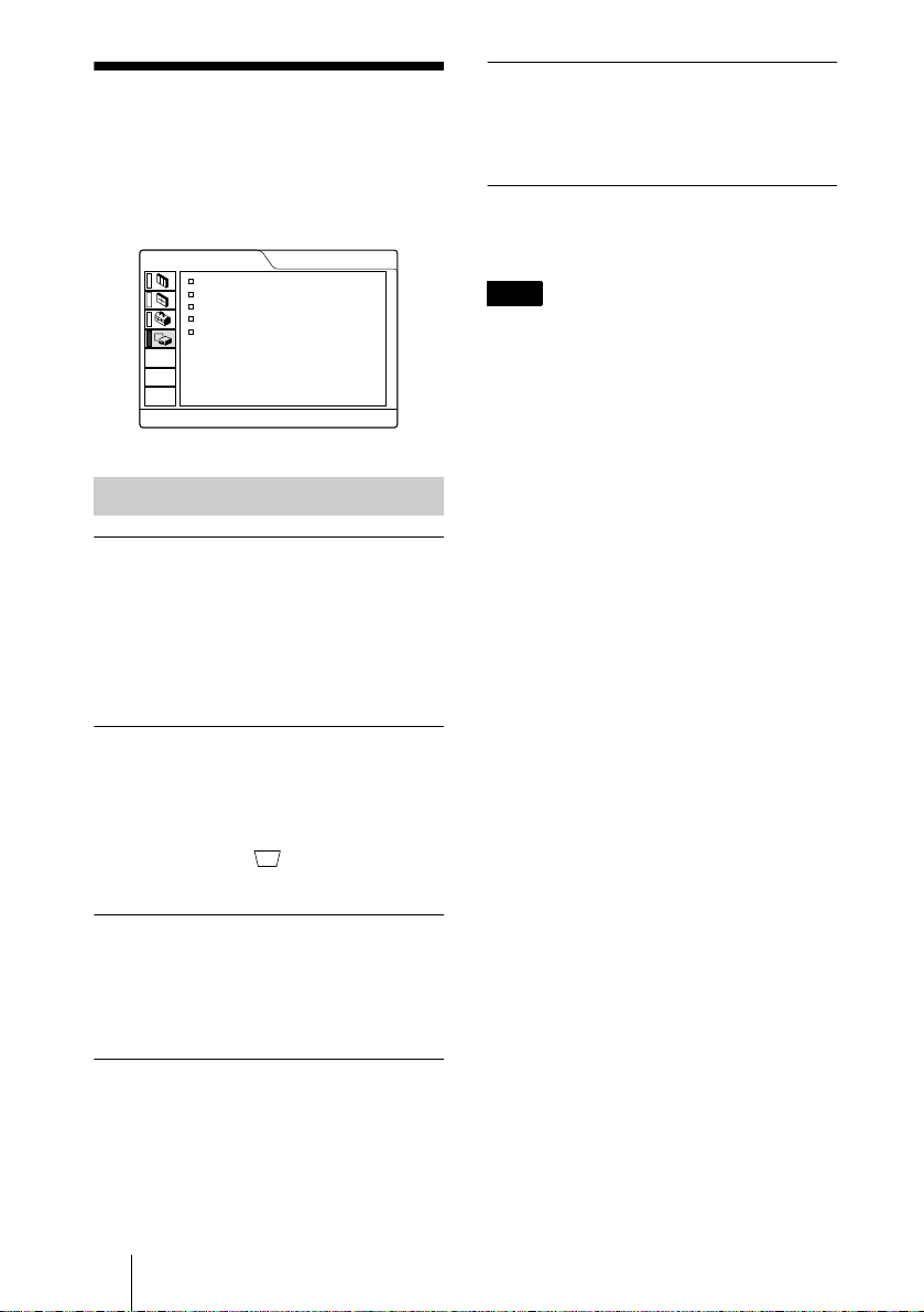
The INSTALL SETTING menu is used for
changing the settings of the projector.
INSTALL SETTING
KEYSTONE MEM
DIGIT KEYSTONE
MENU POSITION
MENU COLOR
MENU BACKGRND
LAMP TIMER:
:
:
:
:
:
ON
0
CENTER
STANDARD
STANDARD
234H
INPUT-A
Menu Items
KEYSTONE MEM
ON: DIGIT KEYSTONE setting is stored.
The data is retrieved whe n th e p rojec to r
power is turned on. The setting will
remain the same every time.
OFF: DIGIT KEYSTONE is reset to 0 when
the power is turned on next time.
DIGIT KEYSTONE
Corrects the trapezoidal distortion caused by
the projection an gle .
LAMP TIMER
Indicates how long the lamp has been turned
on.
Note
This only displays the time. You c annot alter
the display.
When the upside of the trapezoid is longer
than the downside : Sets to a plus
value.
MENU POSITION
Selects the display position of the menu
from TOP LEFT, BOTTOM LEFT,
CENTER, TOP RIGHT and BOTTOM
RIGHT.
MENU COLOR
Selects the tone of the menu display from
STANDARD, WARM, COOL, GREEN or
GRAY.
GB
The INSTALL SETTING Menu
30
 Loading...