

Page 1
3-865-882-11(2)
Video Presentation
Stand
Operating Instructions Page 2
Mode d’emploi Page 24
Bedienungsanleitung Seite 46
GB
FR
DE
VID-P150
1998 by Sony Corporation
Page 2

English
Table of contents
Owner’s Record
The model and serial numbers are located on the rear of the
unit. Record the serial number in the space provided below.
Refer to them whenever you call upon your Sony dealer
regarding this product.
Model No. VID-P150 Serial No.
WARNING
To prevent fire or shock hazard, do not
expose the unit to rain or moisture.
To avoid electrical shock, do not open the
cabinet. Refer servicing to qualified
personnel only.
WARNING
For the customers in the USA
This equipment has been tested and found to comply with
the limits for a Class A digital device, pursuant to Part 15 of
the FCC Rules. These limits are designed to provide
reasonable protection against harmful interference when the
equipment is operated in a commercial environment. This
equipment generates, uses, and can radiate radio frequency
energy and, if not installed and used in accordance with the
instruction manual, may cause harmful interference to radio
communications. Operation of this equipment in a residential
area is likely to cause harmful interference in which case the
user will be required to correct the interference at his own
expense.
You are cautioned that any changes or modifications not
expressly approved in this manual could void your authority
to operate this equipment.
The shielded interface cable recommended in this manual
must be used with this equipment in order to comply with the
limits for a digital device pursuant to Subpart B of Part 15 of
FCC Rules.
For the customers in Canada
This Class A digital apparatus complies with Canadian ICES-
003.
NOTICE FOR THE CUSTOMERS IN THE
UNITED KINGDOM
WARNING
THIS APPARATUS MUST BE EARTHED
IMPORTANT
The wires in this mains lead are coloured in accordance with
the following code:
Green-and-yellow: Earth
Blue: Neutral
Brown: Live
As the colours of the wires in the mains lead of this
apparatus may not correspond with the coloured markings
identifying the terminals in your plug proceed as follows:
The wire which is coloured green-and-yellow must be
connected to the terminal in the plug which is marked by the
letter E or by the safety earth symbol Y or coloured green or
green-and-yellow.
The wire which is coloured blue must be connected to the
terminal which is marked with the letter N or coloured black.
The wire which is coloured brown must be connected to the
terminal which is marked with the letter L or coloured red.
2
Page 3

Table of Contents
Introduction........................................................................ 4
Features ...................................................................................4
System Configuration .............................................................6
Parts Identification ............................................................ 8
Camera and Operation Panel...................................................8
Rear Panel ...............................................................................9
Remote Commander .............................................................10
Preparation....................................................................... 11
Precautions ............................................................................11
Preparing the Remote Commander .......................................11
Setting Up the Unit ...............................................................11
Connecting the Unit to Other Equipment .............................12
Adjusting the Parts ................................................................14
Collapsing the Unit ...............................................................15
GB
English
Operations........................................................................ 16
Basic Operation.....................................................................16
Advanced Operation .............................................................19
Controlling the VID-P150 From a Computer .......................22
Specifications .................................................................. 23
3
Page 4
Introduction
The VID-P150 Video Presentation Stand allows you to
display visual materials such as paper-based
documents, transparent sheets, slides, film negatives,
and solid objects on a color monitor or projector by
shooting them with a color video camera. In addition
to ordinary operations, this unit allows you to control
camera movement using the power scroll function.
Features
The VID-P150 has the following features.
Power scroll function
The power scroll function automatically moves the
camera upward, downward, left and right. You can
control zoom in and out, or shoot material on a wall by
tilting the camera upward through 90 degrees manually
(flip-up).
Easy to adjust
The arm lights turn on and the focus, iris and white
balance adjust automatically after power-on. You can
also adjust each setting manually depending on the
picture you want to display.
Quick response auto focus
When the inner focus lens is used, it can correctly
adjust focus position in only 1 or 2 seconds.
12 × power zoom lens
The 12 × power zoom lens allows you to display
various materials ranging in size from approximately
1
/4" × 29/32" (31 × 23 mm) to approximately 13 7/8" ×
1
1
/4" (350 × 260 mm) sheet on the screen.
10
Pattern memory
Easy to connect
Visuals can be displayed by simply connecting a color
monitor because the camera, lens, light, and power
supply are all incorporated in one unit.
Wireless remote commander
The wireless remote commander allows you remote
control of camera movement of the power scroll
function or zoom.
Sharp screen
The 380,000 (for the NTSC model) or 440,000 (for the
PAL model) pixels of the
allow 460 (for the NTSC model) or 450 (for the PAL
model) horizontal resolution TV lines producing high
screen resolution. An S VIDEO OUT connector allows
you to connect a monitor or projector equipped with an
S VIDEO IN connector, thus giving you even higher
screen resolution.
1
/3-inch CCD pickup device
Four pattern settings, two for document position and
two for flip-up position, can be set. The pattern
memory function memorizes the camera angle, zoom,
focus, iris, white balance, lighting and effect (black &
white, negative) settings. To recall the pattern
memory, press the button you preset.
Easily removable close-up lens
After tilting up the camera, you can easily remove the
close-up lens by revolving it.
Various materials can be shot and
displayed
Various materials from paper-based documents and
transparent sheets to slides, film negatives and solid
objects can be shot and displayed.
To shoot and display film negatives, just press the
appropriate button to change the lighting to the back
light and setting for displaying film negatives.
4
Page 5

Built-in back light
Camera monitor connector
The large-sized built-in back light allows the A4-sized
object such as transparent sheets, slides or film
negatives to be shot and displayed on a monitor. To
use the back light, just press a button.
Built-in video selector
A video selector is incorporated in this unit. It allows
you to switch the pictures shot with this unit to those
from the connected video equipment such as a VCR
and laserdisc player and vice versa.
Sound mixing function
You can add a running commentary simply by
connecting a microphone and a monitor with speakers.
In addition, existing audio signals can be mixed with
the audio signal from the microphone, so you can add
a commentary while displaying video signals via the
built-in video selector on a monitor.
This unit is equipped with a camera monitor connector
which is used to output the pictures shot with this unit.
By connecting the camera monitor connector to a
monitor, you can check the picture while using the
VIDEO1 or VIDEO2 with other video equipment, and
you can also set the PATTERN MEMORY settings.
Accessory shoe for an LCD (liquid crystal
display) monitor
This unit has an accessory shoe for attaching an LCD
monitor. You can use this monitor to conveniently
confirm your view by attaching it to the accessory
shoe.
Various output style
A Y/C separator is incorporated in this unit. It allows
you to output the video signal to either VIDEO OUT
or S VIDEO OUT regardless of the input video signal
from VIDEO IN or S VIDEO IN.
External control from a computer
An RS-232C interface is provided with this unit. This
interface allows the unit to be controlled from an
external computer. However, the software to control
the VID-P150 must first be installed. Refer to the
“Interface Manual” for details on the commands and
communication protocol for this software.
Easy to transport
The unit can be collapsed so easily and weighs so little
that it can be carried with no trouble, allowing you to
make a presentation anywhere.
5
Page 6
Introduction
System Configuration
Basic configuration
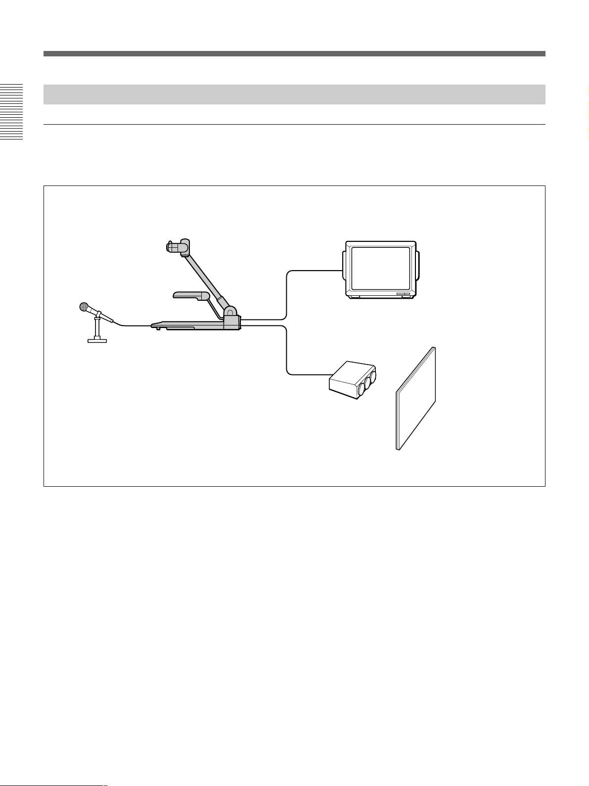
The basic system for making a presentation or
displaying educational materials is as follows:
Color monitor with speakers
Microphone
VID-P150
Projector
Screen
6
Page 7
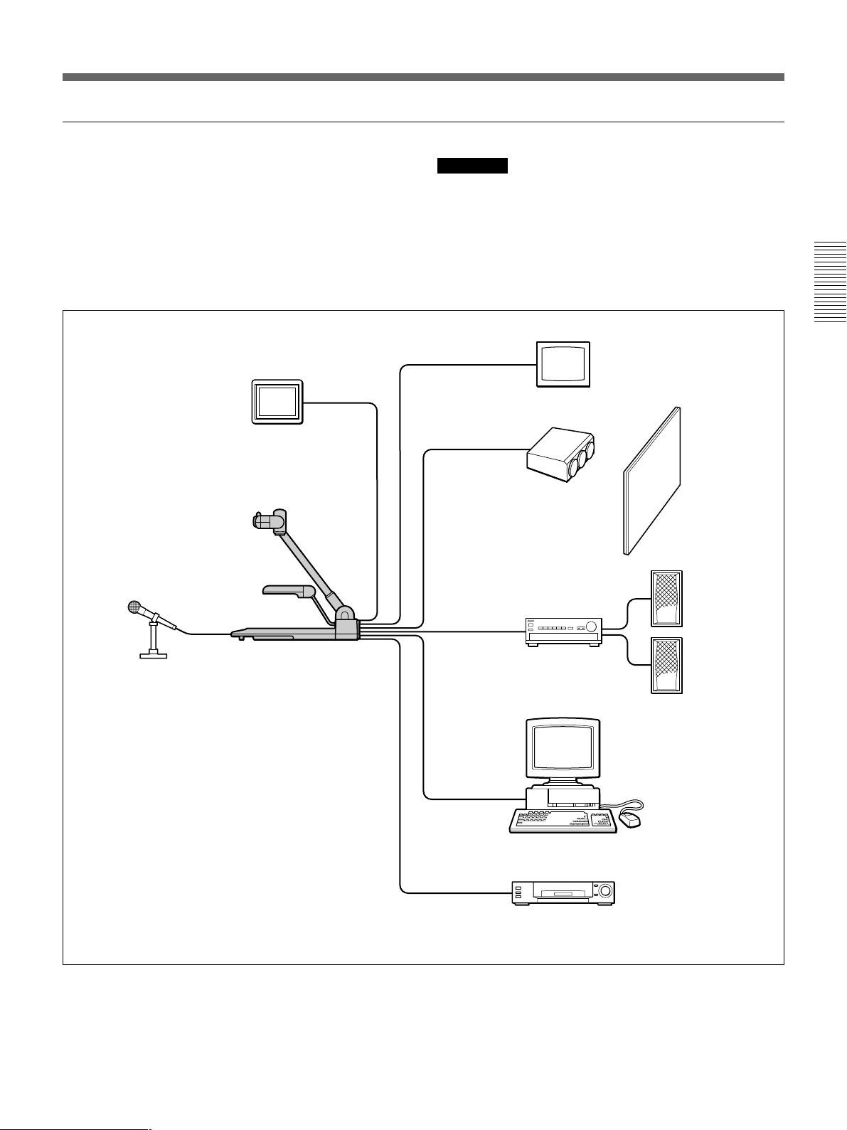
Advanced system
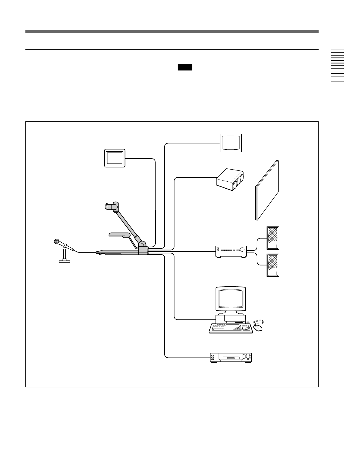
When you connect video equipment such as a VCR or
laserdisc player to this unit, you can switch the picture/
sound to those from the connected video equipment,
and vice versa by using the VIDEO OUT buttons.
When you connect a computer, you can control the
VID-P150 from the computer.
Camera Monitor
Note
When you control the VID-P150 from a computer,
special software is required. To program in this
software, refer to the “Interface Manual”.
Color Monitor
Projector
Screen
Speaker
Microphone
VID-P150
Amplifier
Computer
(For controlling the VID-P150)
Video equipment, etc.
7
Page 8
Parts Identification
For details on the use of each part, see the pages
indicated in parentheses.
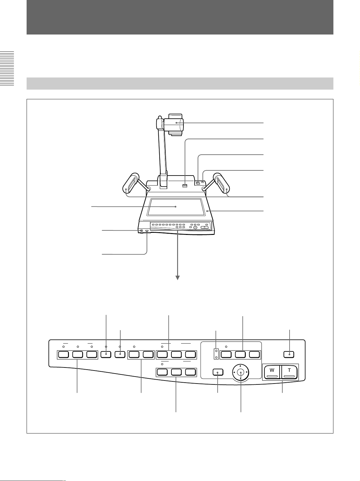
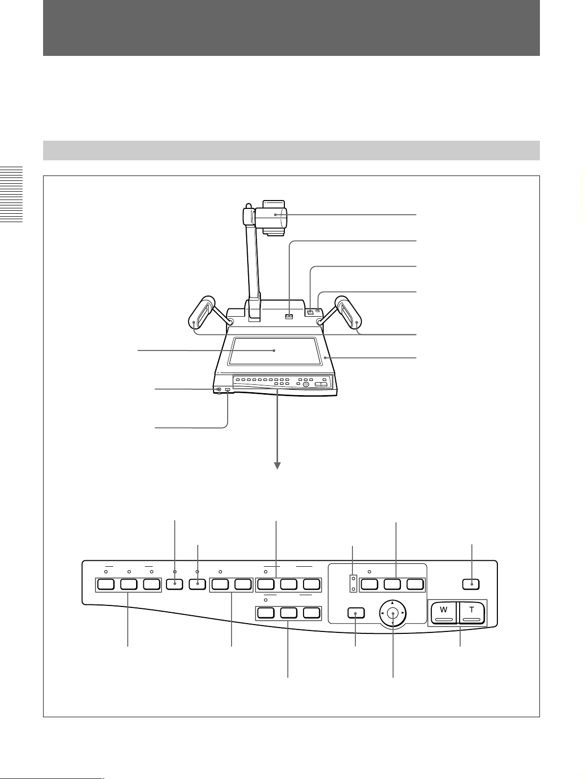
Camera and Operation Panel
Camera
UNLOCK lever (page 11)
POWER switch (page 16)
Accessory shoe (page 22)
Arm lights (page 14,18)
Back light (page 18)
MIC (microphone) connector
(pages 12 and 18)
VOL (microphone volume) control
(page 18)
B&W (black & white) button
(page 21)
VIDEO OUT
CAMERA
VIDEO 2 ONE PUSHVIDEO 1 B&W NEGA AUTO
NEGA (negative) button
(page 21)
EFFECT W.BALANCE
Operation panel
IRIS buttons
(page 20)
Camera position display LED
(page 17)
IRIS
CLOSE OPENAUTO
FOCUS
NEAR FARAUTO
FLIP-UP
DOCUMENT
PATTERN MEMORY buttons
(page 19)
PATTERN MEMORY
SET
12
CAMERA ANGLE
HOME
Stage
LIGHTING button
(page 18)
LIGHTING
ZOOM
VIDEO OUT (output)
buttons
(page 18)
W.BALANCE
(white balance)
buttons
(page 21)
FOCUS buttons
(page 20)
HOME button
(page 17, 20)
CAMERA ANGLE buttons
(page 16)
ZOOM buttons
(page 17)
8
Page 9
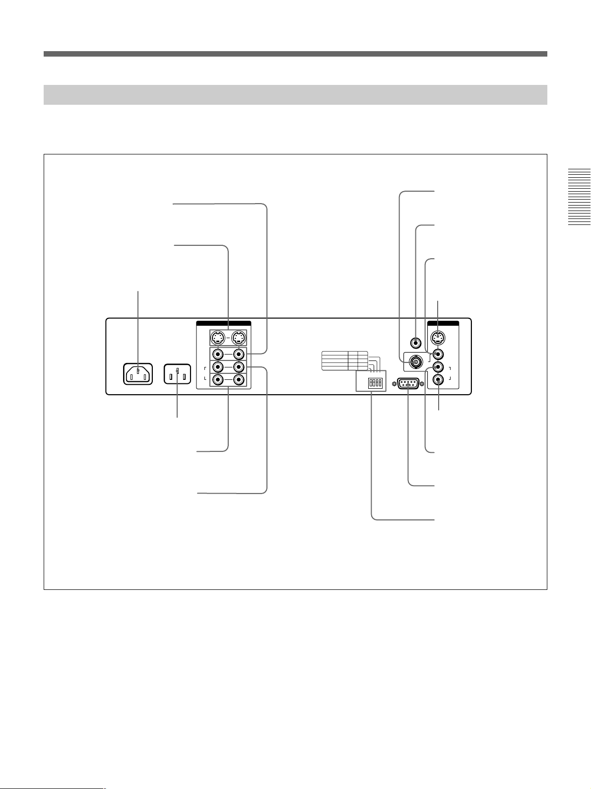
Rear Panel
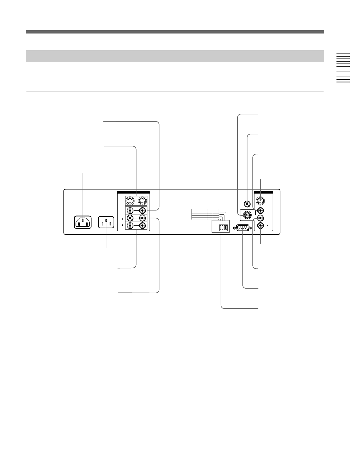
For details on the use of the connectors, see pages 12
and 13.
VIDEO IN connectors 1,2
(phono)
S VIDEO IN connectors 1,2
(4-pin mini DIN)
VIDEO OUT 2 connector
(BNC type)
CAMERA MONITOR connetor
(phono)
VIDEO OUT 1 connector
(phono)
AC IN connector
S VIDEO
AC OUT
AC IN
AC 120V 60Hz
UNSWITCHED
MAX 300W
VIDEO
AUDIO
AC OUT receptacle (NTSC model only)
AUDIO R IN connectors 1,2 (phono)
AUDIO L IN connectors 1,2 (phono)
VIDEO 1
L
R
S VIDEO OUT connector
(4-pin mini DIN)
IN
VIDEO 2
1234
ON
OFF
CAMERA
MONITOR
RS-232C
OUT
S VIDEO
VIDEO 1
2
L
AUDIO
R
AUDIO R OUT
connector (phono)
AUDIO L OUT
connector (phono)
RS-232C connector
(D-sub 9-pin, male)
BIT switch (Camera angle
and remote commander
setting switch)
(page 22)
9
Page 10
Parts Identification
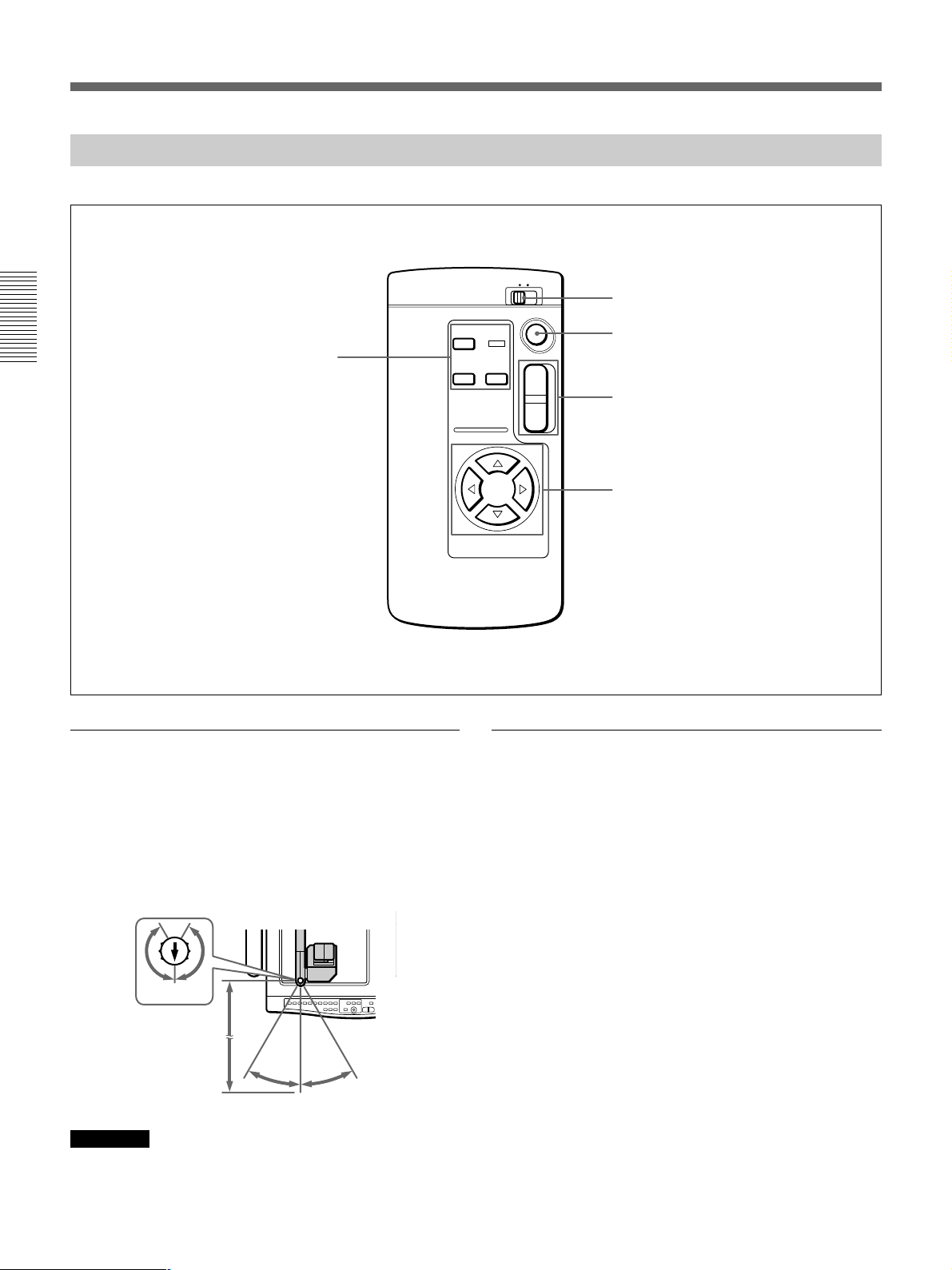
Remote Commander
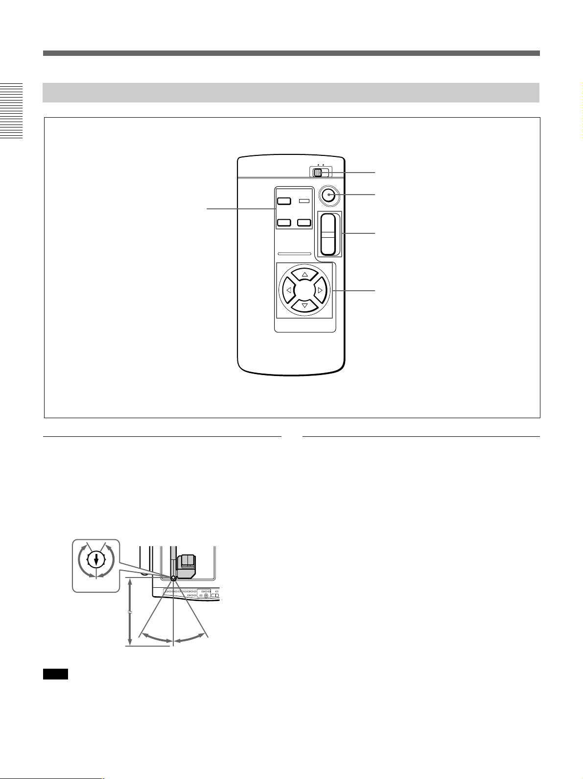
PATTERN MEMORY buttons (page 19)
SET
1 2
PATTERN
MEMORY
CAMERA ANGLE
1
2
HOME
W
REMOTE COMMANDER number switch
(page 22)
HOME button (page 17,20)
T
ZOOM buttons (page 17)
CAMERA ANGLE buttons (page 16)
Remote control range
The remote control range is 5m (15 1/3 ft) at 30 degrees
either side in the direction of the white arrow on the
top of the remote sensor. The remote sensor can be
adjusted 150 degrees to either side as viewed from the
front of this unit.
150° 150°
5m (15 1/3 ft)
30°
30°
Note
Be sure that there is no obstacle between the remote
sensor and the remote commander.
Checking the remote control
When the remote commander does not work, check
the following:
• BIT switch settings on the rear panel are wrong
(page 22).
– REMOTE CONTROL is OFF.
n Set to ON.
– REMOTE COMMANDER number is wrong.
n Set the number correctly.
• Batteries are weak.
n Replace both batteries.
• The remote sensor and the remote commander do
not face each other.
n Adjust the direction.
10
Page 11
Preparation
Precautions
•Unplug the VID-P150 from the wall outlet when it is
not being used for a long period of time. To
disconnect the cord, pull it out by grasping the plug.
Never pull it out by the cord itself.
•The fluorescent lamps can get hot during operation.
Do not touch the lamps during operation and when
collapsing the VID-P150.
•Clean the cabinet with a soft cloth lightly moistened
with a mild detergent solution. Never use any type of
solvent such as alcohol or benzine, which might
damage the finish.
•Clean the lens with an air spray or soft dry cloth,
taking care not to scratch it.
•When the fluorescent lamps flash or get darkened, the
fluorescent lamps should be replaced with new ones.
In this case, contact your Sony dealer.
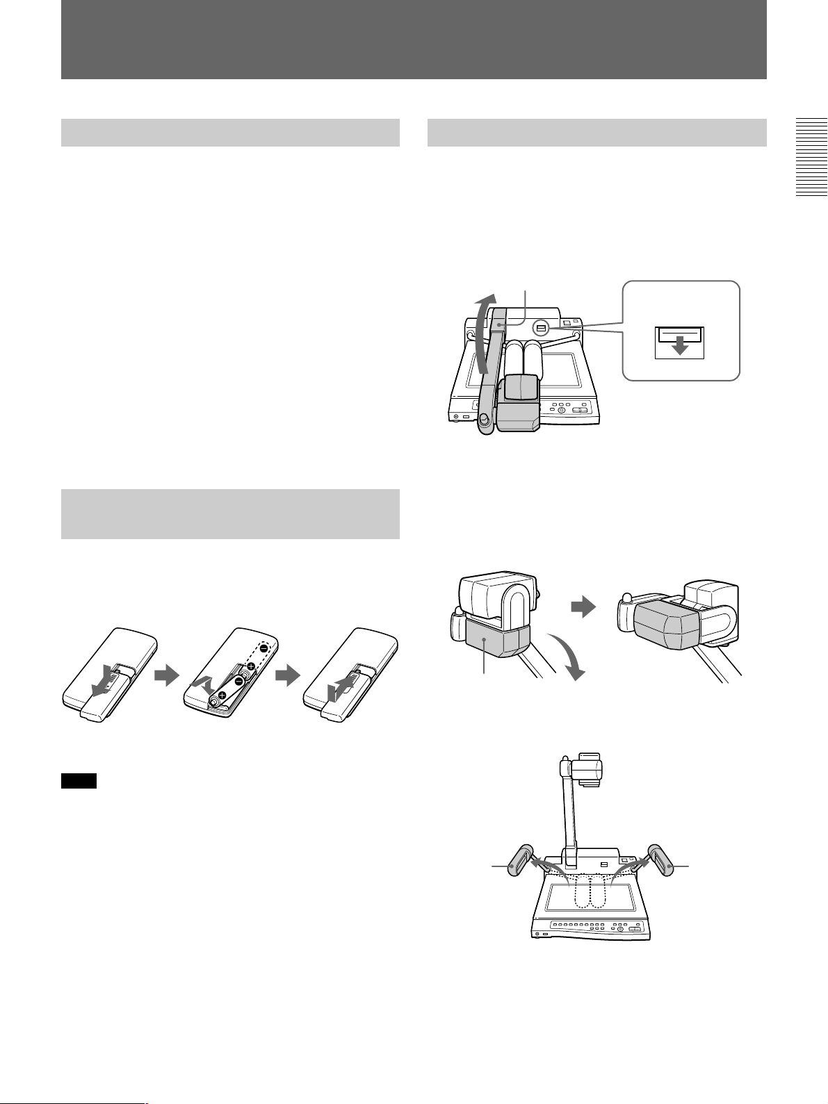
Preparing the Remote Commander
Insert two R6 (size AA) batteries by matching the ‘
and ’ on the batteries to the diagram inside the battery
compartment.
Setting Up the Unit
1 Lift up the camera stand while keeping the
UNLOCK lever pressed down.
If you cannot press down the UNLOCK lever, fold
the camera stand down toward the operation panel
until it touches the stage, then press down the
UNLOCK lever again.
Camera stand
UNLOCK lever
2 Move the camera downward.
When the camera is in the flip-up position, move
the cover manually in the direction of the arrow.
Turning on the POWER returns the camera lens to
the home position.
Note
When the batteries for the remote commander are
weak, the remote control range shortens. When this
happens, replace both batteries.
Cover
3 Open both arm lights until they fix in place.
Arm light
Arm light
4 Connect the power cord to the AC IN connector on
the rear panel.
11
Page 12

Preparation
Connecting the Unit to Other Equipment
Notes on connections
•Before making any connections, turn off the power of
the VID-P150 and the equipment to be connected.
Example of connections to this unit
Front
•For NTSC model only: Before connecting a device
such as a monitor to the VID-P150 AC OUT
receptacle, check to see if the power consumption is
2.5 A or less. Do not connect any device whose
power consumption is over 2.5 A to the VID-P150.
Microphone
Rear
AC outlet
AC power cord (supplied)
AC IN
VID-P150
(Rear panel)
S VIDEO IN 1 or 2
DIN 4-pin cable
S video
output
connector
a)
or
VIDEO IN
1 or 2
Video
cable
Video
output
connector
AC OUT (NTSC
model only)
AUDIO L, R
1 or 2
Audio cable
Audio output
connectors
Video equipment
MIC
AC power cord (not supplied)
VIDEO OUT (phono jack)
Video cable
VIDEO OUT 1
(phono jack)
S VIDEO OUT
(4-pin DIN)
DIN 4-pin cable
Video cable
VIDEO OUT 2
(BNC type)
AUDIO L and
R OUT
VID-P150 (Front)
or
Audio cable
Audio
input connectors
AC inlet
Video input
connector
Video input
connector
S video input
connector
a)
Projector
Video input connector
Amplifier
Camera monitor
Color monitor
Screen
Speaker
a) It is recommended that you use the DIN 4-pin cable when
you connect this unit to the equipment with an S video
input or output connector.
12
Page 13
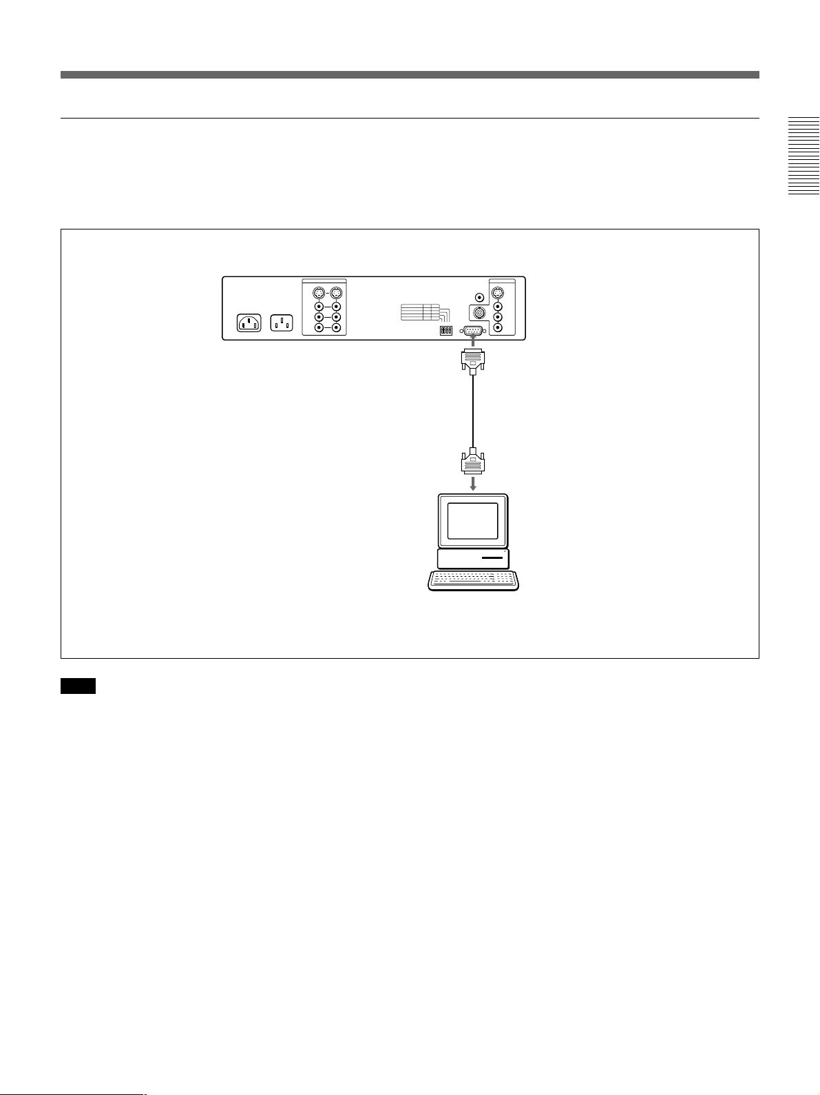
Connections for external control from a computer
After performing the connections on the previous
page, make the connections shown below to control
this unit from the connected computer.
VID-P150 (Rear panel)
RS-232C
(D-sub 9-pin, male)
RS-232C cable
RS-232C connector
of the computer
Note
When you control the VID-P150 from a computer,
special software is required. To program in this
software, refer to the “Interface Manual”.
13
Page 14

Preparation
Adjusting the Parts
Adjusting the camera
The VID-P150 allows you to shoot in two positions:
the document position is for shooting material on the
stage, the flip-up position is for shooting material on a
wall by tilting the camera upward through 90 degrees
manually.
Move the cover manually to adjust the camera to the
document position or the flip-up position to meet your
needs.
Flip-up position
Document position
Adjusting the arm lights
Adjust the angle of the arm lights depending on the
object.
If the light supporting arms loosen
If the arms will not stay upright, the screw in the base
may be loose. After turning off the POWER switch,
tighten the screw as shown below.
The arm cannot stand upright.
Document position
Cover
Flip-up position
Opening in the base for
adjusting the light
supporting arm
Tighten the screw inside
slightly, but not excessively.
Cross-headed screwdriver
14
Page 15
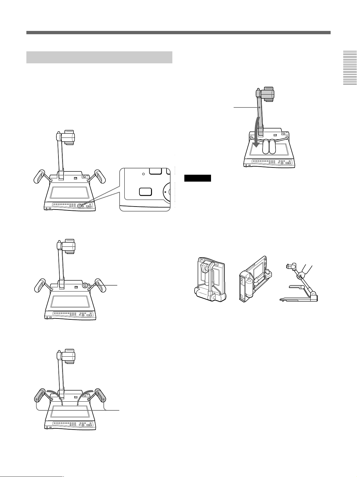
Collapsing the Unit
Follow the instructions below to collapse the VIDP150 for transportation or convenience.
1 Press the HOME button to set the camera angle to
the preset position (page 20). When the camera is
in the flip-up position, move the cover manually to
the document position.
HOME
2 Turn off the POWER.
4 Carefully fold down the camera stand toward the
operation panel side until it locks.
Camera stand
Cautions
•Lay the unit down flat. Do not try to stand it on its
rear or sides. Doing so may cause the unit to fall
resulting in damage or personal injury.
•Do not try to pick up this unit by the camera stand.
This may cause the unit to malfunction, and may
cause you injury.
POWER switch
3 Fold both arm lights down onto the base.
Arm lights
NOT this way
NOT this way
NOT this way
15
Page 16
Operations
This section explains two things: the basic operation
for displaying normal materials and the advanced
operation for displaying special materials such as film
negatives.
Basic Operation
Turning on the power (POWER switch)
Press the POWER switch to turn on the power. The
VID-P150 automatically sets the camera to the home
position, turns on the arm lights, adjusts the focus, iris
(brightness), and white balance. While adjusting the
settings, the CAMERA indicator flashes for about 6
seconds and you cannot operate the ZOOM, FOCUS,
IRIS or W.BALANCE buttons. When the VID-P150
finishes adjusting the settings, the CAMERA indicator
light stays on and now you can use this unit.
The only things left to do are to adjust the camera
angle and to zoom the image on the screen to display a
normal document.
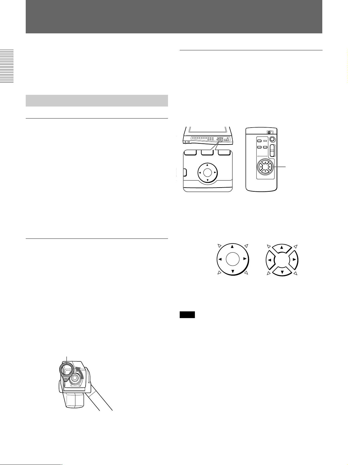
Changing the camera direction
Adjusting the camera angle
(CAMERA ANGLE buttons)
To change the camera angle, press the CAMERA
ANGLE buttons on the operation panel or on the
remote commander. The camera angle can be set to
either 8 or 4 directions using the BIT switch setting on
the rear panel (page 22). You can set camera direction
for forward or backward shooting.
T
W
CAMERA ANGLE
Camera angle direction
8 directions: 4¢
4 directions: 4
CAMERA ANGLE buttons
On the operation panel
On the remote commander
CAMERA ANGLE
buttons
The VID-P150 allows you to shoot in two positions:
the document position is for shooting material on the
stage, the flip-up position is for shooting material on a
wall by tilting the camera upward through 90 degrees
manually. At each position, you can move the camera
from left to right, or up and down using the power
scroll function. This allows you to shoot and display
the audience, students, or even yourself. To shoot an
object in the flip-up angle and far away from the VIDP150 itself, remove the close-up lens.
To remove the close-up lens
Close-up lens
Revolve.
Replace the close-up lens after operation.
On the remote commander, press the two buttons side
by side to move in the desired diagonal direction
(¢direction).
Note
When the camera angle does not move diagonally or
the camera moves backward, check the BIT switch
setting on the rear panel (page 22).
• CAMERA ANGLE is set to OFF (4-WAY).
n Set to ON (8-WAY).
• CAMERA DIRECTION is set to OFF (REV).
n Set to ON (STD).
16
Page 17
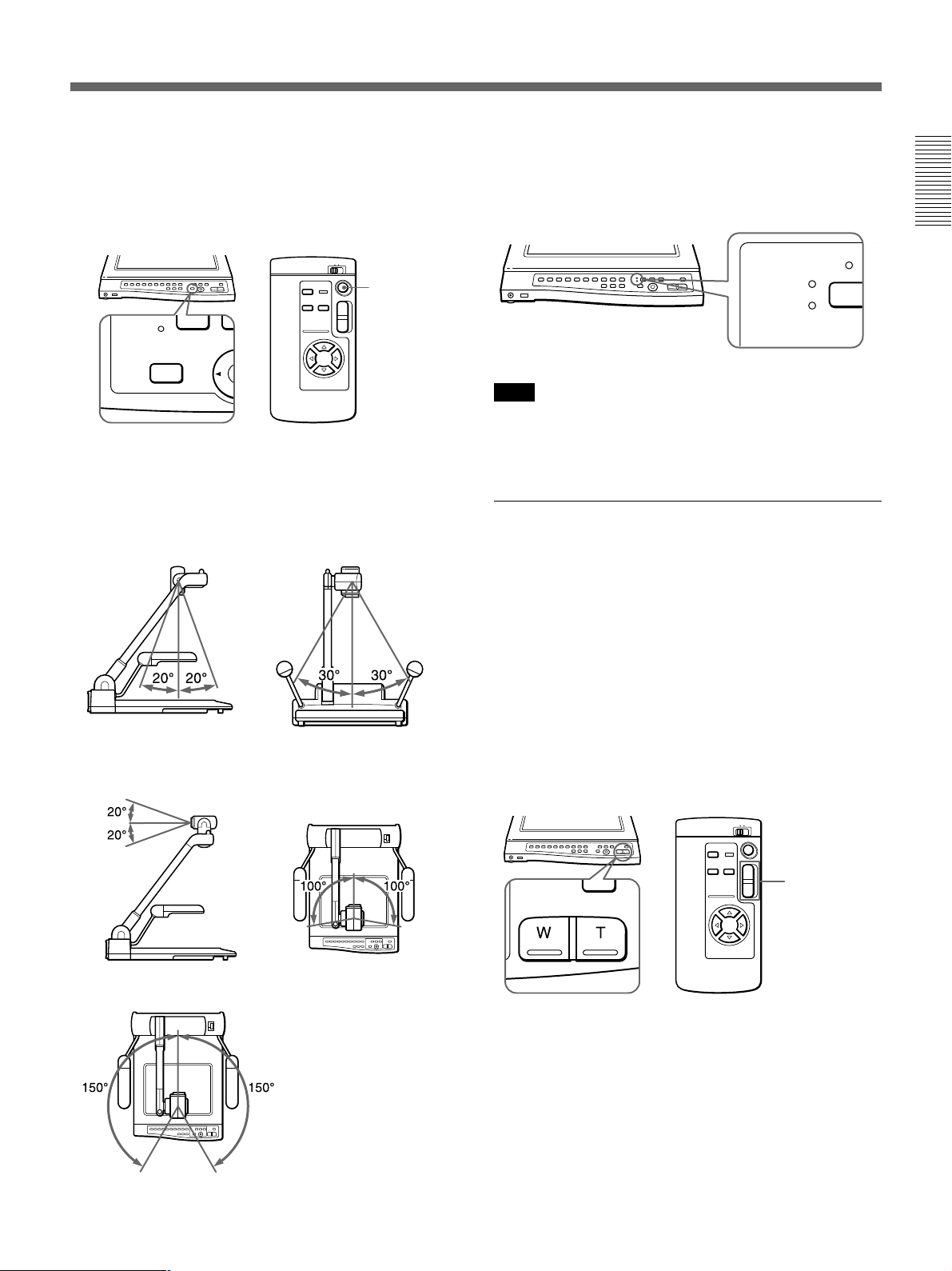
To replace camera angle
Press the HOME button on the operation panel or on
the remote commander.
The HOME button is for both document and flip-up
position (page 20).
Camera position display LED
When shooting on the stage, DOCUMENT lights.
Tilting the camera upward through 90 degrees
manually causes FLIP-UP to light.
HOME button
T
W
HOME
Camera angle range
Camera angle can be changed in two positions.
For quick movement, move the camera manually.
Document position
Flip-up position
Automatic operation range
FLIP-UP
DOCUMENT
Note
Turn off automatic operation when operating this unit
manually. Moving or stopping the camera by hand in
automatic operation may cause malfunctions.
Zooming the image on the screen
(ZOOM buttons)
To zoom into or out from the image on the screen, use
the ZOOM buttons on the operation panel or on the
remote commander.
To zoom out from the image for panoramic long shots,
press the W (wide-angle) button. To zoom into the
image for close-ups, press the T (telephoto) button.
The VID-P150 offers two levels of speed zooming.
Press the button firmly for high speed zooming and
softly for slower zooming on the operation panel.
On the remote commander, press and hold the ZOOM
buttons for high speed zoom.
Manual operation range
ZOOM
T
W
ZOOM buttons
17
Page 18
Operations
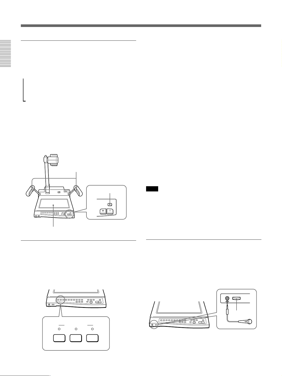
Switching the lighting (LIGHTING button)
The arm lights turn on automatically when the power
is switched on. Each time you press the LIGHTING
button, the lighting changes as follows.
The arm light turns on.
m
µ
The back light turns on.
µ
All the lights tuns off.
When shooting and displaying transparencies such as
transparent sheets, slides and film positive, press the
LIGHTING button to switch the light from the arm
lights to the back light.
When you press the LIGHTING button repeatedly,
wait 1 second before you press the LIGHTING button
again.
Arm lights
To output the video signal from the VID-P150
camera and the audio signal from the
microphone connected to the MIC connector
Press the CAMERA button. The video signal from the
camera of the VID-P150 and the audio signal from the
microphone connected to the MIC connector are
automatically output.
When turned on, the video signal from the camera is
automatically output.
To output a signal from the video equipment
connected to the VID-P150
Press the VIDEO 1 or VIDEO 2 button.
The VIDEO IN connectors on the rear panel are
interlocked to the VIDEO buttons, the VIDEO IN 1
connector to the VIDEO 1 button and the VIDEO IN 2
connector to the VIDEO 2 button.
When the microphone is connected, this unit outputs
sound by mixing the audio signal from the AUDIO IN
connectors with the audio signal from the microphone.
When you want to switch the video signal from the
input connectors to the camera, press the CAMERA
button.
LIGHTING button
Back light
Selecting the signals to output
(VIDEO OUT buttons)
The VIDEO OUT buttons on the operation panel
allow you to switch the pictures shot with this unit to
those from the connected video equipment and vice
versa.
VIDEO OUT
CAMERA
VIDEO 2VIDEO 1
Note
When you connect video equipment to both the S
VIDEO IN 1 connector and the VIDEO IN 1 connector
on the rear panel, the video signal from the S VIDEO
IN 1 connector is automatically output. It is the same
when you connect both the VIDEO IN 2 and S VIDEO
IN 2 connectors.
Adjusting the microphone level
(VOL control)
Use the VOL control on the front of the VID-P150 to
adjust the level of the microphone connected to the
MIC connector. Turn it to the right to increase the
volume. Turn it to the left to decrease the volume.
MIC
VOL control
Microphone
18
Page 19
Advanced Operation
Adjusting the image to your taste
The VID-P150 automatically adjusts the focus, iris and
white balance when you turn on the power and set the
material to be displayed in the middle of the screen.
You can also adjust them yourself manually as you
wish.
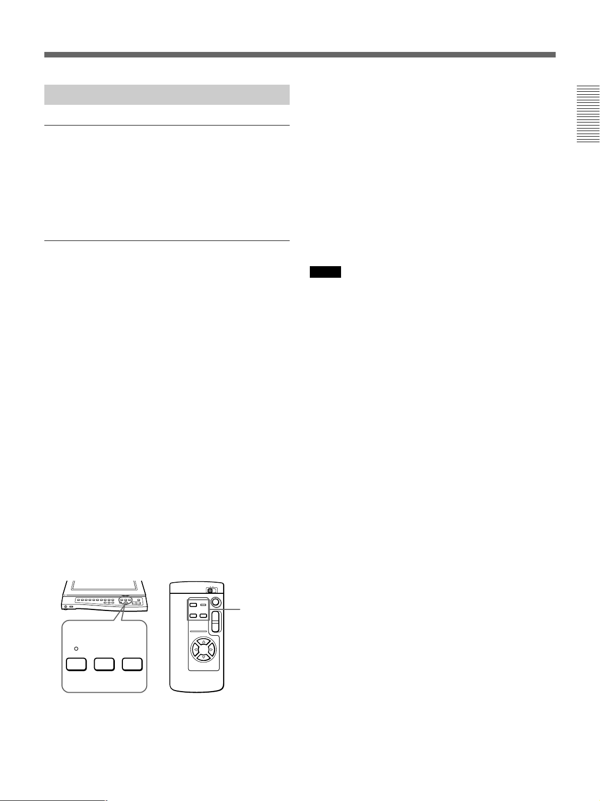
Presetting the pattern memory
(PATTERN MEMORY buttons)
The PATTERN MEMORY buttons on the operation
panel or on the remote commander allow you to preset
four pattern settings, two for document position and
two for flip-up position. The pattern memory function
memorizes the camera angle, zoom, focus, iris, white
balance, lighting and effect (black & white, negative)
settings. Once you have preset the pattern memory for
an object you use often, you can recall the pattern
memory by pressing the button you preset.
1 Adjust the camera angle, zoom, focus, iris, white
balance, lighting and effect (black & white,
negative) settings.
When the setting has not been properly memorized
If the PATTERN MEMORY SET indicator does not
light for about 2 seconds, or a beep does not sound
when using the remote commander, the setting may
not have been properly memorized. In this case, repeat
steps 1 to 3.
To recall the setting you preset
To recall the document position setting, set the camera
manually to document position, to recall the flip-up
position setting, set the camera manually to flip-up
position, then press the PATTERN MEMORY 1 or 2
button.
Notes
• If you set the PATTERN MEMORY setting when the
camera is in the flip-up position and the camera angle
is out of the automatic operation range, the camera
angle is set to the widest angle possible in the
automatic operation range (100°) (page 17).
•When you recall the pattern memory setting, the
position may not be exactly the same as it was set.
Adjust the camera angle if necessary.
•When you turn on the power, or the pattern memory
has not been set, the PATTERN MEMORY 1 or 2 is
the factory setting except the home position setting.
•The setting you preset will be reset when you turn off
the power.
2 Press the PATTERN MEMORY SET button.
3 Press the PATTERN MEMORY 1 or 2 button
while the PATTERN MEMORY SET indicator is
flashing fast (for about 5 seconds).
The PATTERN MEMORY SET indicator lights
for about 2 seconds and then turns off. When
using the remote commander, a beep sounds.
PATTERN
T
W
PATTERN MEMORY
12SET
MEMORY
buttons
19
Page 20
Operations
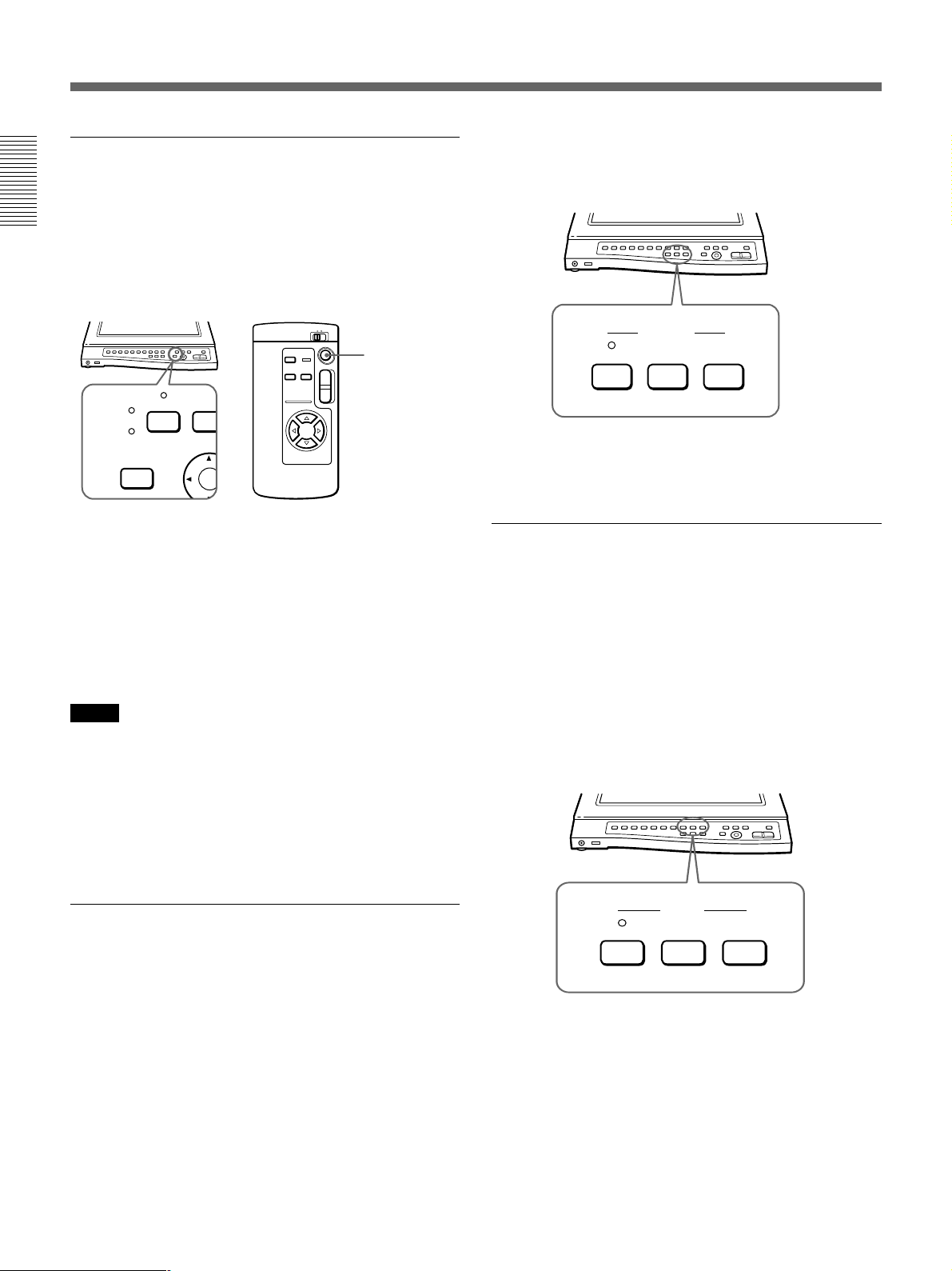
Returning to the home position
(HOME button)
Press the HOME button on the operation panel or on
the remote commander. The camera angle and zoom
revert to the preset angle and focus becomes
automatic. The HOME button is for both document
and flip-up positions.
HOME button
T
SET
HOME
Changing the home position setting
You can change the camera angle and zoom for the
position you want to set. While pressing the SET
button on the operation panel, press the HOME button
for 5 seconds. When the setting is finished, a beep
sounds. Only camera angle and zoom can be set by the
HOME button. The home position setting is retained
even when you turn off the POWER.
Notes
• The home position (camera angle and zoom) is the
same for both document and flip-up position. When
you change the home position setting in the document
position, the home position setting in the flip-up
position is also changed.
• You can not change the home position setting on the
remote commander.
W
If you move the camera angle while the focus is
locked, it will become out of focus. In this situation,
set the focus to automatic.
FOCUS
NEAR FARAUTO
To go back to automatic focus
Press the AUTO button to light the AUTO indicator.
Adjusting the iris (Brightness) manually
(IRIS buttons)
Use the IRIS buttons on the operation panel to adjust
the iris (brightness). To increase the brightness, press
the OPEN button. To decrease the brightness, press the
CLOSE button. Adjust the iris manually when you
want to display:
•an object which reflects light strongly and the picture
looks whitish,
•a pale-colored film negative, or
•the contrast strongly.
Adjusting the focus manually
(FOCUS buttons)
Use the FOCUS buttons on the operation panel to
adjust the focus. You can also adjust the focus for a
three-dimensional object by using the NEAR and FAR
buttons. Adjust the focus manually when you display:
•a material that includes small type or fine patterns
which are difficult to focus,
•a material of low contrast, or
•a three-dimensional object.
You can lock the focus when the focus is adjusted
automatically. Press the FAR or NEAR button once to
lock the focus.
20
IRIS
CLOSE OPENAUTO
To go back to automatic iris
Press the AUTO button to light the AUTO indicator.
Page 21
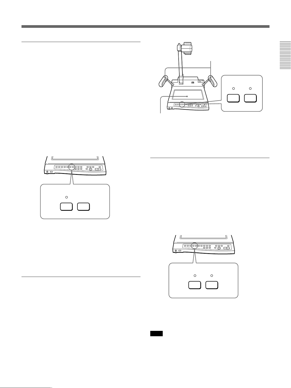
Locking the white balance setting
(W.BALANCE buttons)
The VID-P150 automatically adjusts the white
balance. You can lock the white balance setting when
the object color is not displayed naturally. This is
useful when you display:
•a monochromatic material (including film negatives)
or background, or
•a pale colored material.
To lock the white balance setting, press the ONE
PUSH button. The white balance setting which adjusts
immediately before you pressed the button is held.
In the ONE PUSH mode, it locks the last automatic
white balance setting and maintains it even when the
lighting conditions change. This allows the color of the
material to be displayed naturally.
W.BALANCE
ONE PUSHAUTO
To go back to automatic white balance
Press the AUTO button to light the AUTO indicator
when you change the object to be shot or the color of
the material is not displayed naturally in the ONE
PUSH mode. The VID-P150 unlock the white balance
setting and adjust the white balance automatically.
Displaying film negatives
(EFFECT buttons)
Arm lights
EFFECT
B&W NEGA
Back light
To display a normal material on the screen
Press the NEGA button when the NEGA indicator is
lit. The NEGA indicator turns off and the arm lights
turn on.
Setting the screen in monochrome mode
(EFFECT buttons)
To set the screen in monochrome, press the B&W
button. The B&W indicator lights to indicate that the
screen is now set to monochrome. We recommend that
you set the screen to monochrome when you display:
•a black and white material such as a black and white
document or a black and white film, or
•a material which includes small type such as a
newspaper and fine patterns.
EFFECT
B&W NEGA
The VID-P150 is automatically set to display normal
materials on the screen when you turn it on. Press the
NEGA button on the operation panel to display the
film negatives. The NEGA indicator above the button
lights, and the arm lights go off and the back light
comes on. The VID-P150 begins to display the
reverse picture of the film negatives.
To display film negatives more naturally, see also
“Locking the white balance setting (W.BALANCE
buttons)”.
To set the screen in color
Press the B&W button again. The B&W indicator
turns off and the screen is set to the normal color.
Note
When you shoot and display a finite pattern such as a
column of newsprint, it is recommended to set the
screen to monochrome and connect a monitor via the S
VIDEO OUT connector.
21
Page 22
Operations
Camera angle and remote commander
setting (BIT switch)
The functions of BIT switch (camera angle and remote
commander setting switch) are as follows. Set the
switch to meet your needs.
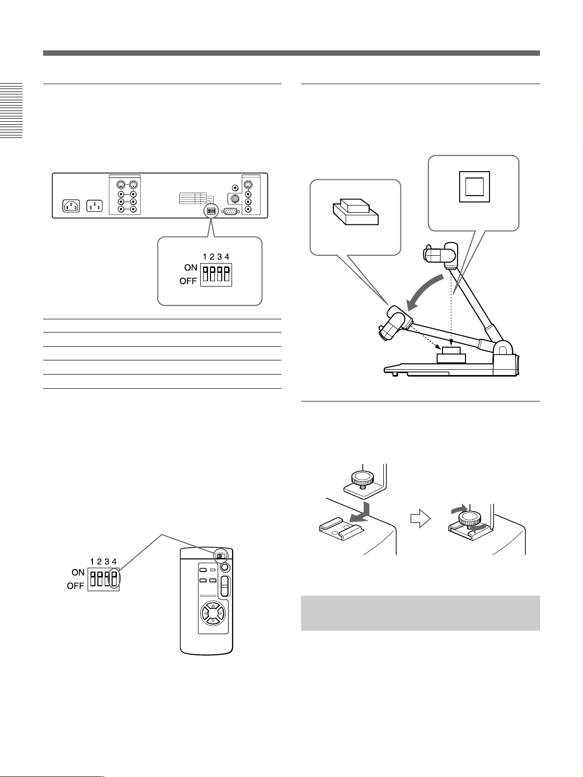
BIT SWITCH ONa) OFF
4 REMOTE COMMANDER 1 2
3 REMOTE CONTROL ON OFF
2 CAMERA DIRECTIONb) STD REV
1 CAMERA ANGLE 8-WAY 4-WAY
Shooting a three-dimensional object
To shoot and display a three-dimensional object, lower
the camera stand. You can also shoot it from one
angle.
Shoot the object
from the top.
Shoot the object
from one angle.
Lower the
camera stand.
a) All switches are set to ON at the factory.
b) STD (forward) is when the camera moves in the same
direction as the camera angle buttons. REV (backward) is
when it moves in reverse of the camera angle buttons.
The remote commander number
Match the REMOTE COMMANDER number with the
BIT switch on the rear panel and with the REMOTE
COMMANDER number switch on the remote
commander.
To match the REMOTE COMMANDER number
T
W
Using the accessory shoe for an LCD
monitor
This unit has an accessory shoe for attaching an LCD
monitor.
Tighten the lock knob.
Controlling the VID-P150 From a Computer
You can control the VID-P150 from a computer
connected by an RS-232C connector. However, the
software to control the VID-P150 must first be
installed. Refer to the “Interface Manual” for details
on the communication protocol for this software.
22
Page 23

Specifications
Color system NTSC or PAL color system
1
Pickup device
/3" interline transfer method, CCD
(Charge Coupled Device)
Resolution NTSC model
Horizontal: 460 TV lines
Vertical: 350 TV lines
PAL model
Horizontal: 450 TV lines
Vertical: 400 TV lines
Picture elements 380,000, 768 × 494 (H/V)
(NTSC model)
440,000, 752 × 582 (PAL model)
Filming range Approximately 350 × 260 mm
7
/8 × 10 1/4 inches) (at wide-
(13
angle)
Approximately 31 × 23 mm
1
/4 × 29/32 inches) (at telephoto)
(1
Lens 12 × power zoom lens
7
f = 5.4 to 64.8 mm (
/32 to 2 5/8
inches)
F = 1.8 to 2.7
Zoom Electrically powered
(Two levels of speed zooming)
Focus Auto/manual selectable
Iris Auto/manual selectable
White balance Auto/one push (fixed) selectable
Positive/negative film selection function
Possible
Monochrome/color selection function
Possible
Pattern memory 4 settings (2 for document angle,
2 for flip-up angle)
Camera movement range (automatic)
Document angle
Panning ±30°, Tilting ±20°
Flip-up angle
Panning ±100° (manual ±150°)
Tilting ±20°
Camera movement speed
Panning/Tilting Approximately 6°/
second (Changed according to the
zoom position.)
Output signal selection
One output from three
(CAMERA/VIDEO1/VIDEO2)
Light Arm light: 9 W twin-fluorescent
lamp × 2
Back light: 2.5 W cold cathode
fluorescent lamp × 2
Input connectors VIDEO IN (phono jack) (2)
1 Vp-p, 75 Ω, sync negative
S VIDEO IN (4-pin mini DIN) (2)
Y: 1 Vp-p, 75 Ω, sync negative
C: 0.286 Vp-p, 75 Ω
(NTSCmodel)
0.300 Vp-p, 75 Ω(PAL model)
AUDIO IN L/R (phono jacks)
(2 each)
Input impedance: 47 kΩ
Level: –10 dB, unbalanced
MIC input (phone jack) (1)
Input impedance: 3.3 kΩ
Level: –60 dB, unbalanced
Output connectors VIDEO OUT (BNC type) (1)
1 Vp-p, 75 Ω, sync negative
VIDEO OUT (phono jack) (1)
1 Vp-p, 75 Ω, sync negative
CAMERA MONITOR OUT
(phono jack)(1)
1 Vp-p, 75 Ω, sync negative
S VIDEO OUT (4-pin mini DIN)(1)
Y: 1 Vp-p, 75 Ω, sync negative
C: 0.286 Vp-p, 75 Ω
(NTSC model)
0.300 Vp-p, 75 Ω (PAL model)
AUDIO OUT L/R (phono jacks)
(1 each)
Output impedance:
less than 600 Ω
Level: –10 dB, unbalanced
RS-232C connector
D-sub, 9-pin, male
Power requirements
120 V AC, 60 Hz (NTSC model)
230 V AC, 50/60 Hz (PAL model)
AC output AC OUT (auxiliary AC outlet)
(NTSC model only)
maximum 2.5 A/unswitched
Power consumption
120 V, 3 A (NTSC model)
230V, 0.3 A (PAL model)
Dimensions After set up: Approximately
446 × 625 × 622 mm (w/h/d)
5
/8 × 24 5/8 × 24 1/2 inches)
(17
After collapsed: Approximately
446 × 190 × 711 mm (w/h/d)
5
/8 × 7 1/2 × 28 inches)
(17
Mass Approximately 8.8 kg (19 lb 6 oz)
Supplied accessories
AC power cord (1)
Remote commander RMT-P150(1)
R6 (size AA) batteries (2)
Operation manual (1)
Interface manual (1)
Design and specifications are subject to change
without notice.
23
Page 24

Français
Table des matières
AVERTISSEMENT
Afin d’éviter tout risque d’incendie ou d’électrocution, ne pas
exposer l’appareil à la pluie ou à l’humidité.
Afin d’écarter tout risque d’électrocution, garder le coffret
fermé. Ne confier l’entretien de l’appareil qu’à un personnel
qualifié.
Pour les utilisateurs au Canada
Cet appareil numérique de la classe A est conforme à la
norme NMB-003 du Canada.
24
Page 25
Table des matières
Introduction...................................................................... 26
Caractéristiques.....................................................................26
Configuration système ..........................................................28
Identification des composants....................................... 30
Caméra et panneau de commande.........................................30
Panneau arrière......................................................................31
Télécommande ......................................................................32
Préparation....................................................................... 33
Précautions ............................................................................33
Préparation de la télécommande ...........................................33
Installation de l’appareil........................................................33
Raccordement de l’appareil à d’autres équipements.............34
Réglage des différents éléments............................................36
Démontage de l’appareil .......................................................37
Opérations........................................................................ 38
Opérations de base ................................................................38
Opérations avancées..............................................................41
Commande du VID-P150 depuis un ordinateur....................44
Spécifications .................................................................. 45
FR
Français
25
Page 26
Introduction
Le support de présentation vidéo VID-P150 vous
permet de visualiser sur un moniteur couleur ou à
l’aide d’un projecteur des éléments visuels tels que des
documents imprimés, des transparents, des
diapositives, des films négatifs ainsi que des objets
tridimensionnels en en réalisant une prise de vue au
moyen d’une caméra vidéo couleur.
En plus des opérations ordinaires, cet appareil vous
permet de commander les mouvements de la caméra à
l’aide de la fonction de déplacement motorisé.
Caractéristiques
Le VID-P150 présente les caractéristiques suivantes.
Fonction de déplacement motorisé
La fonction de déplacement motorisé déplace
automatiquement la caméra vers le haut, le bas, la
gauche et la droite. Vous pouvez commander le zoom
avant et arrière ou encore réaliser une prise de vue
d’un sujet sur un mur en inclinant manuellement la
caméra de 90 degrés vers le haut (basculement).
Simplicité de réglage
Les bras d’éclairage s’allument et la mise au point, le
diaphragme et la balance des blancs se règlent
automatiquement à la mise sous tension. Vous pouvez
également régler chacun des paramètres manuellement
en fonction de l’image que vous voulez visualiser.
Mise au point rapide
L’objectif à mise au point intérieure permet de régler
correctement la mise au point en l’espace d’une ou
deux secondes.
Zoom motorisé 12 ×
Le zoom motorisé 12 × vous permet d'afficher à l'écran
les objets les plus divers dont la taille peut aller de 31
× 23 mm (1
7
/8" × 10 1/4").
(13
1
/4" × 29/32") à une feuille de 350 × 260 mm
Mémoire de mode de réglage
Simplicité de raccordement
Le VID-P150 vous permet de visualiser des objets en
raccordant simplement un moniteur couleur puisque la
caméra, l’objectif, l’éclairage et le dispositif
d’alimentation sont intégrés dans l’appareil.
Télécommande sans fil
La télécommande sans fil vous permet de commander
à distance les mouvements de la caméra, la fonction de
déplacement motorisé ou le zoom.
Netteté de l’écran d’affichage
Les 380.000 pixels (pour le modèle NTSC) ou 440.000
pixels (pour le modèle PAL) du dispositif de prise de
vue de 1/3 de pouce à couplage de charge permettent
une définition horizontale de 460 lignes TV (pour le
modèle NTSC) ou de 450 lignes TV (pour le modèle
PAL), soit un écran à haute résolution. Un connecteur
S VIDEO OUT vous permet de raccorder un moniteur
ou un projecteur équipé d’un connecteur S VIDEO IN,
ce qui vous offre une résolution encore supérieure.
Quatre modes de réglage, deux pour la position du
document et deux pour la position de basculement,
peuvent être ajustés. La fonction de mémoire de mode
de réglage mémorise l’angle de la caméra ainsi que les
réglages du zoom, de la mise au point, du diaphragme,
de la balance des blancs, de l’éclairage et de l’effet
(noir & blanc, négatif). Pour restaurer la mémoire de
réglage, appuyez sur la touche de présélection.
Lentille de gros plan aisément amovible
Après avoir fait basculer la caméra, vous pouvez
aisément retirer la lentille de gros plan en la faisant
tourner.
26
Page 27

Prise de vue et visualisation de divers
objets
Commande à distance depuis un
ordinateur
Cet appareil permet la prise de vue et la visualisation
de différents objets allant des documents imprimés et
des transparents aux diapositives, aux films négatifs et
aux objets tridimensionnels.
Pour la prise de vue et la visualisation de films
négatifs, il vous suffit d’appuyer sur la touche
appropriée pour passer de l’éclairage au rétro-éclairage
et modifier le réglage pour la visualisation de films
négatifs.
Rétro-éclairage intégré
Le dispositif de rétro-éclairage intégré de grandes
dimensions permet la prise de vue et la visualisation
sur un moniteur d’objets de format A4 tels que des
transparents, des diapositives ou des films négatifs. Il
vous suffit d’appuyer sur une touche pour utiliser le
rétro-éclairage.
Sélecteur vidéo intégré
Un sélecteur vidéo est intégré dans cet appareil. Il vous
permet de commuter les prises de vue réalisées au
moyen de cet appareil et les images d’un appareil
vidéo raccordé comme un magnétoscope ou un lecteur
de vidéodisques.
Fonction de mixage du son
Vous pouvez ajouter un commentaire en raccordant
simplement un microphone et un moniteur doté de
haut-parleurs. Les signaux audio existants peuvent
également être mixés avec le signal audio du
microphone, de telle sorte que vous pouvez ajouter un
commentaire pendant la visualisation sur un moniteur
de signaux vidéo via le sélecteur vidéo intégré.
Une interface RS-232C est fournie avec cet appareil.
Cette interface permet de commander l’appareil depuis
un ordinateur externe. Il convient cependant d’installer
au préalable le logiciel de commande du VID-P150.
Reportez-vous au mode d’emploi de l’interface pour
plus de détails sur les commandes et le protocole de
communication pour ce logiciel.
Simplicité de transport
Comme l’appareil se démonte en un tour de main et
pèse très peu, vous pouvez le transporter sans aucun
problème en vue de réaliser une présentation où bon
vous semble.
Connecteur du moniteur de caméra
Cet appareil est équipé d’un connecteur de moniteur de
caméra servant à transmettre les images enregistrées à
l’aide de cet appareil. En raccordant le connecteur de
moniteur de caméra à un moniteur, vous pouvez
contrôler l’image après avoir connecté VIDEO1 ou
VIDEO2 à un appareil vidéo, et vous pouvez aussi
programmer les réglages PATTERN MEMORY.
Sabot porte-accessoire pour moniteur
LCD (à affichage à cristaux liquides)
Cet appareil est doté d’un sabot porte-accessoire pour
la fixation d’un moniteur LCD. Vous pouvez utiliser
ce moniteur pour vérifier convenablement la
visualisation en le fixant sur le sabot porte-accessoire.
Différents modes de sortie
Un séparateur Y/C est intégré dans cet appareil. Il vous
permet de sortir le signal vidéo via VIDEO OUT ou S
VIDEO OUT quel que soit le signal vidéo entré via
VIDEO IN ou S VIDEO IN.
27
Page 28
Introduction
Configuration système
Configuration de base
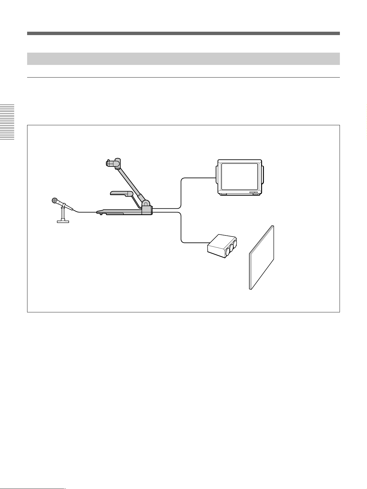
Le système de base pour la réalisation d’une
présentation ou la visualisation de documents éducatifs
se compose de la façon suivante:
Moniteur couleur
avec haut-parleurs
Microphone
VID-P150
Projecteur
Ecran
28
Page 29
Système avancé
En raccordant un appareil vidéo comme un
magnétoscope ou un lecteur de disques laser à cet
appareil, vous pouvez commuter l’image/son de la
caméra et de l’appareil vidéo raccordé à l’aide des
touches VIDEO OUT. Si vous raccordez un
ordinateur, vous pouvez commander le VID-P150
depuis l’ordinateur.
Moniteur de caméra
Remarque
Pour commander le VID-P150 depuis un ordinateur,
vous avez besoin d’un logiciel spécial. Pour
programmer ce logiciel, reportez-vous au mode
d’emploi de l’interface.
Moniteur couleur
Projecteur
Ecran
Haut-parleur
Microphone
VID-P150
Amplificateur
Ordinateur
(Pour commander le VID-P150)
Appareil vidéo, etc.
29
Page 30
Identification des composants
Pour plus de détails sur l’utilisation de chaque
composant, reportez-vous aux pages indiquées entre
parenthèses.
Caméra et panneau de commande
Caméra
Levier UNLOCK (page 33)
Commutateur POWER (page 38)
Sabot porte-accessoire (page 44)
Rétro-éclairage
(page 40)
Connecteur MIC (microphone)
(pages 34 et 40)
Commande VOL
(volume microphone)
(page 40)
VIDEO OUT
CAMERA
VIDEO 2 ONE PUSHVIDEO 1 B&W NEGA AUTO
Panneau de commande
Touche B&W (noir & blanc)
(page 43)
Touche NEGA (négatif)
(page 43)
EFFECT W.BALANCE
Touches IRIS (page 42)
DEL d’indication de
position de la caméra
(page 39)
IRIS
CLOSE OPENAUTO
FOCUS
NEAR FARAUTO
FLIP-UP
DOCUMENT
Bras d’éclairage (page 36 et 40)
Plateau
Touches PATTERN MEMORY
(page 41)
PATTERN MEMORY
SET
12
CAMERA ANGLE
HOME
Touche LIGHTING
(page 40)
LIGHTING
ZOOM
30
Touches VIDEO OUT
(sortie) (page 40)
Touches
W.BALANCE
(balance des
blancs) (page 43)
Touche HOME
(page 39 et 42)
Touches FOCUS
(page 42)
Touches ZOOM (page 39)
Touches CAMERA ANGLE
(page 38)
Page 31
Panneau arrière
Pour plus de détails sur l’utilisation des connecteurs,
reportez-vous aux pages 34 et 35.
Connecteurs VIDEO IN 1,2
(phono)
Connecteurs S VIDEO IN 1,2
(miniconnecteur DIN à 4 broches)
Connecteur AC IN
Connecteur VIDEO OUT 2
(type BNC)
Connecteur
CAMERA MONITOR
(phono)
Connecteur VIDEO OUT 1
(phono)
Connecteur S VIDEO OUT
(miniconnecteur DIN à 4
broches)
S VIDEO
AC OUT
AC IN
AC 120V 60Hz
UNSWITCHED
MAX 300W
VIDEO
AUDIO
Prise AC OUT (modèle NTSC uniquement)
Connecteurs AUDIO R IN 1,2 (phono)
Connecteurs AUDIO L IN 1,2 (phono)
VIDEO 1
L
R
IN
VIDEO 2
1234
ON
OFF
CAMERA
MONITOR
RS-232C
OUT
S VIDEO
VIDEO 1
2
L
AUDIO
R
Connecteur AUDIO
R OUT (phono)
Connecteur AUDIO
L OUT (phono)
Connecteur RS-232C
(D-sub à 9 broches, mâle)
Commutateur BIT (réglage
de l’angle du caméra et de
la télécommande)
(page 44)
31
Page 32
Identification des composants
Télécommande
Touches PATTERN MEMORY
(page 41)
SET
1 2
PATTERN
MEMORY
1
2
HOME
W
Commutateur numérique REMOTE
COMMANDER (page 44)
Touche HOME (page 39 et 41)
T
Touches ZOOM (page 39)
Touches CAMERA ANGLE (page 38)
Portée efficace de la télécommande
La télécommande offre une portée efficace de 5 m (15
1
/3 ft) suivant un angle de 30 degrés dans les deux
directions de la flèche blanche au dessus du capteur de
télécommande. Le capteur de télécommande peut être
réglé suivant un angle de 150 degrés de part et d’autre,
vu depuis l’avant de cet appareil.
150° 150°
5 m (15 1/3 ft)
30°
30°
CAMERA ANGLE
Vérification de la télécommande
Si la télécommande ne fonctionne pas, vérifiez les
éléments suivants:
•Les réglages du commutateur BIT sur le panneau
arrière sont incorrects (page 44).
– REMOTE CONTROL est OFF
n Réglez-le sur ON.
– Le numéro REMOTE COMMANDER est
incorrect.
n Réglez correctement le numéro.
•Les piles sont plates.
n Remplacez les piles.
•Le capteur de télécommande et la télécommande ne
se font pas face.
n Réglez la direction.
Remarque
Veillez à ce qu’il n’y ait aucun obstacle entre le
capteur et la télécommande.
32
Page 33

Préparation
Précautions
•Débranchez le VID-P150 de la prise murale si vous
prévoyez de ne pas l’utiliser pendant une période
prolongée. Pour débrancher le cordon, saisissez-le par
la fiche. Ne tirez jamais sur le cordon proprement dit.
•Les lampes fluorescentes peuvent s’échauffer en
cours d’utilisation. Ne touchez pas les lampes en
cours d’utilisation ou lors du démontage du VIDP150.
•Nettoyez le châssis à l’aide d’un chiffon doux
légèrement imprégné d’une solution détergente
neutre. N’utilisez aucun type de solvant comme de
l’alcool ou de la benzine, qui risquerait de ternir le
fini.
•Nettoyez l’objectif à l’air comprimé ou au moyen
d’un chiffon doux et sec en veillant à ne pas le
griffer.
•Lorsque les lampes fluorescentes se mettent à
clignoter ou qu'elles s'assombrissent, cela signifie
qu'il est temps de les remplacer par des nouvelles.
Dans ce cas, consultez votre revendeur Sony.
Préparation de la télécommande
Installation de l’appareil
1 Soulevez le support de caméra tout en maintenant
le levier UNLOCK abaissé.
Si vous ne parvenez pas à abaisser le levier
UNLOCK, repliez le support de caméra vers le
panneau de commande jusqu’à ce qu’il entre en
contact avec le plateau, et abaissez ensuite à
nouveau le levier UNLOCK.
Support de caméra
Levier UNLOCK
2 Déplacez la caméra vers le bas.
Lorsque la caméra se trouve en position basculée,
déplacez le couvercle manuellement dans le sens
de la flèche. Lorsque vous enclenchez le
commutateur POWER, l’objectif de la caméra
revient dans sa position de repos.
Introduisez deux piles R6 (AA) en en respectant la
polarité ‘ et ’ indiquée par le diagramme à
l’intérieur du compartiment à piles.
Remarque
Lorsque les piles de la télécommande s’épuisent, la
portée efficace diminue. Lorsque cela se produit,
remplacez les piles.
Couvercle
3 Ouvrez les deux bras d’éclairage jusqu’à ce qu’ils
se verrouillent en position.
Bras
d’éclairage
Bras
d’éclairage
4 Branchez le cordon d’alimentation sur la prise AC
IN du panneau arrière.
33
Page 34
Préparation
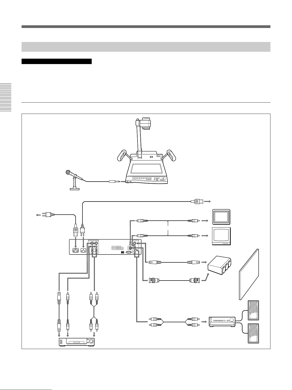
Raccordement de l’appareil à d’autres équipements
Remarques sur le raccordement
•Avant d’établir quelque raccordement que ce soit,
mettez le VID-P150 et l’appareil à raccorder hors
tension.
Exemple de raccordement à cet appareil
Avant
Microphone
MIC
Arrière
Cordon d’alimentation (non fourni)
•Sur le modèle NTSC uniquement: Avant de raccorder
un appareil comme un moniteur à la prise AC OUT
du VID-P150, vérifiez si sa consommation électrique
ne dépasse 2,5 A. Ne raccordez aucun appareil dont
la consommation électrique est supérieure à 2,5 au
VID-P150.
VID-P150 (avant)
Prise AC
Prise murale (secteur)
Cordon d’alimentation
(fourni)
AC IN
VID-P150
(panneau arrière)
S VIDEO IN 1 ou 2
Câble DIN à
4 broches
Connecteur
de sortie
S-VIDEO
ou
a)
VIDEO IN
1 ou 2
Câble
vidéo
Connecteur
de sortie
vidéo
AC OUT
(modèle NTSC
uniquement)
AUDIO L,
R 1 ou 2
Câble audio
Connecteurs de
sortie audio
Appareil vidéo
VIDEO OUT
(prise phono)
VIDEO OUT 1
(prise phono)
S VIDEO OUT
(DIN à 4 broches)
Câble DIN à 4 broches
VIDEO OUT 2
(type BNC)
AUDIO L et
R OUT
Câble vidéo
ou
Câble vidéo
Câble audio
Connecteur
d’entrée vidéo
Connecteur
d’entrée vidéo
Connecteur d’entrée
S-VIDEO
a)
Connecteur
d’entrée vidéo
Connecteurs
d’entrée audio
Moniteur de caméra
Moniteur couleur
Projecteur
Ecran
Amplificateur
Haut-parleur
a) Si vous raccordez cet appareil à un équipement doté d’un
connecteur d’entrée ou de sortie S-VIDEO, nous vous
conseillons d’utiliser le câble DIN à 4 broches.
34
Page 35
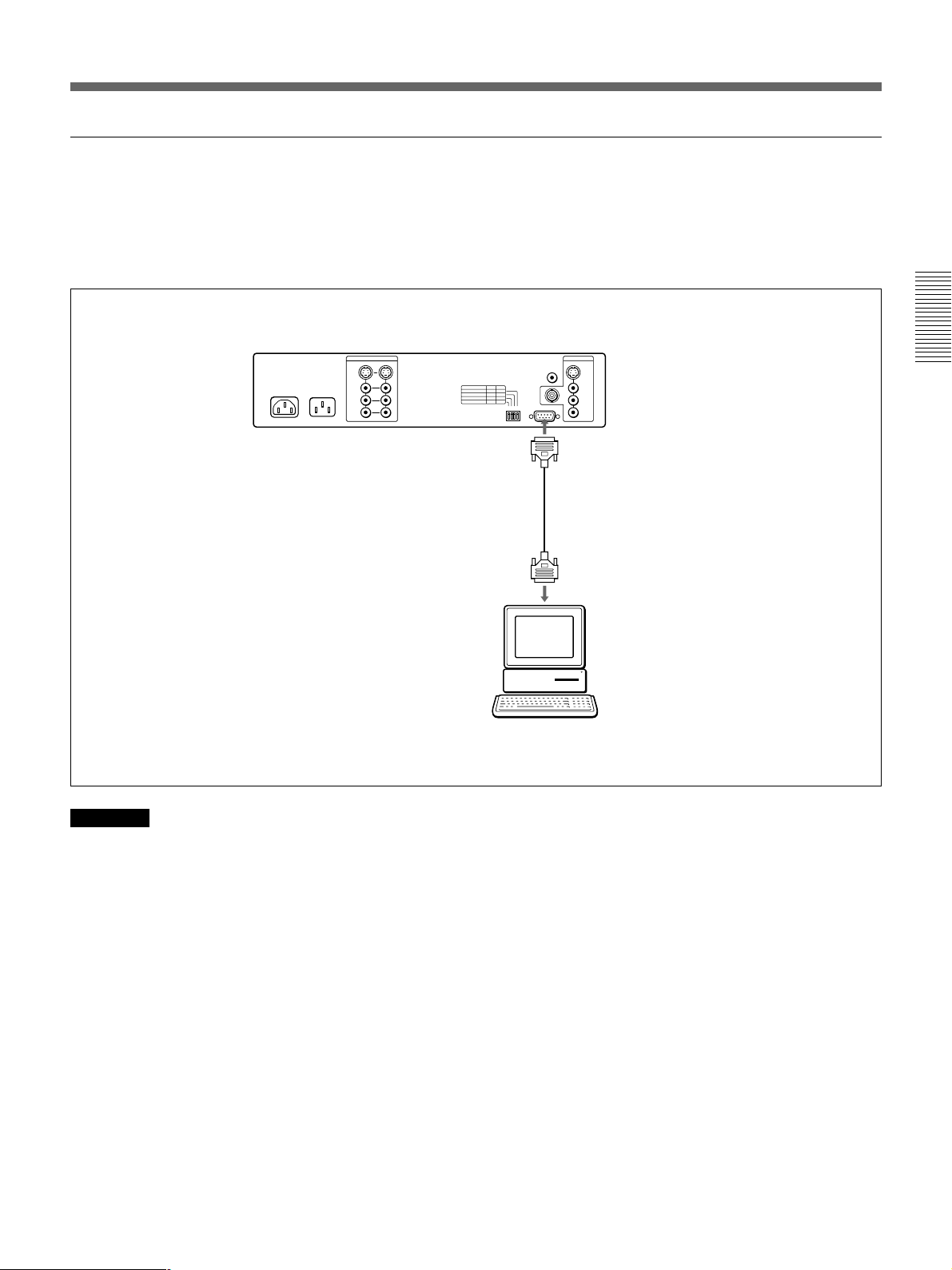
Raccordement pour une commande à distance depuis un ordinateur
Après avoir établi les raccordements de la page
précédente, établissez les raccordements ci-dessous
pour pouvoir commander cet appareil depuis
l’ordinateur raccordé.
VID-P150 (panneau arrière)
RS-232C
(D-sub à 9 broches, mâle)
Câble RS-232C
Connecteur RS-232C
de l’ordinateur
Remarque
Pour commander le VID-P150 depuis un ordinateur,
vous avez besoin d’un logiciel spécial. Pour
programmer ce logiciel, reportez-vous au “Interface
Manual (Mode d’emploi de l’interface)”.
35
Page 36
Préparation
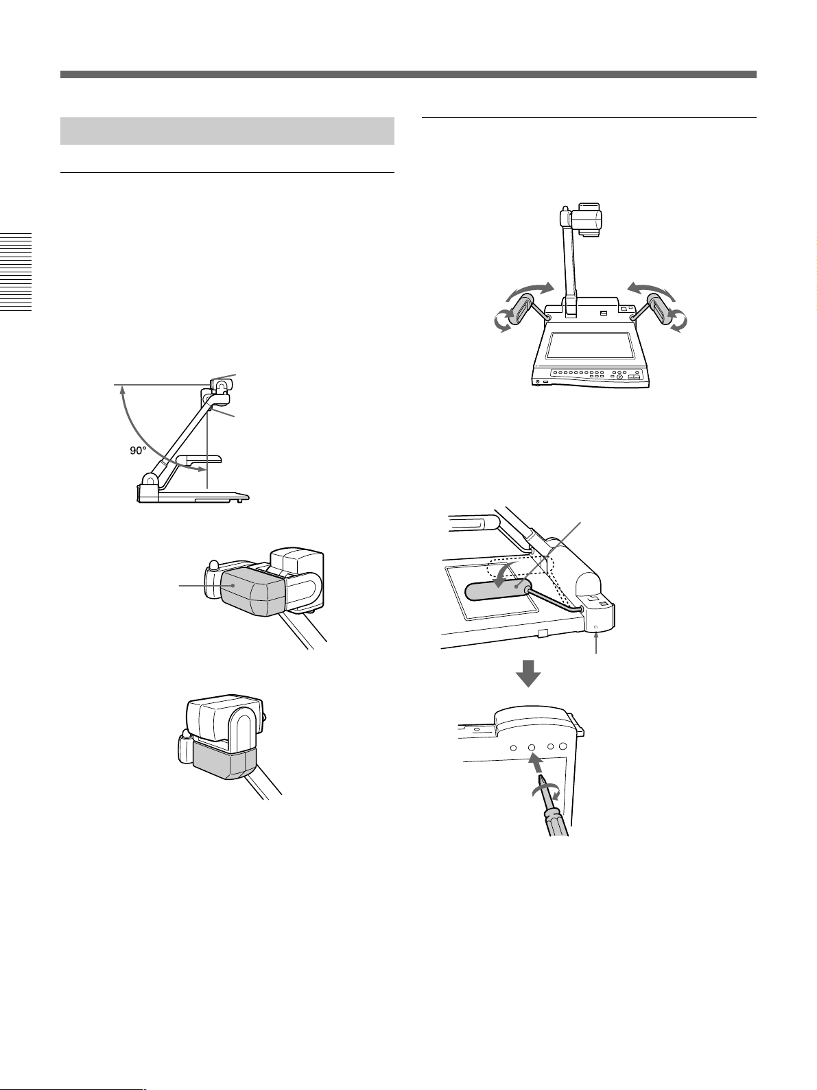
Réglage des différents éléments
Réglage de la caméra
Le VID-P150 permet de réaliser des prises de vues
dans deux sens: la position pour documents pour les
prises de vue de sujets placés sur le plateau, la position
de basculement pour les sujets fixés au mur grâce à
une inclinaison manuelle à 90 degrés de la caméra.
Déplacez le couvercle pour amener la caméra en
position de documents ou de basculement en fonction
de vos besoins.
Position de basculement
Position du document
Position du document
Réglage des bras d’éclairage
Réglez l’angle des bras d’éclairage en fonction de
l’objet.
Si les bras de support d’éclairage se desserrent
Si les bras refusent de rester en position verticale, cela
signifie probablement que la vis située dans le socle est
desserrée. Après avoir réglé le commutateur POWER
sur “OFF”, serrez la vis comme illustré ci-dessous.
Le bras ne reste pas vertical.
Couvercle
Position de basculement
Ouverture dans le socle
pour le réglage du bras
de support d’éclairage.
Serrez légèrement la vis à
l’intérieur, sans forcer.
Tournevis cruciforme
36
Page 37
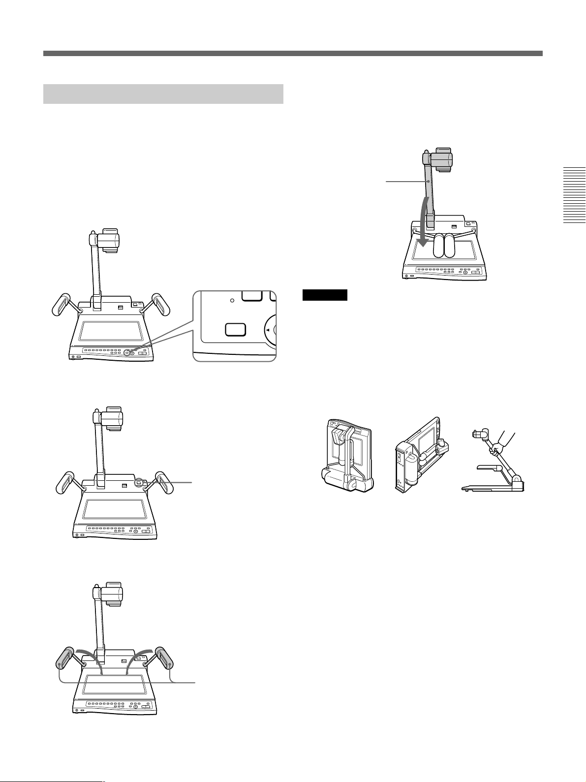
Démontage de l’appareil
Suivez les instructions suivantes pour démonter le
VID-P150 en vue de son transport ou de son rangement.
1 Appuyez sur le bouton HOME pour régler l’angle
de la caméra sur la position présélectionnée (page
42). Lorsque la caméra se trouve en position de
basculement, déplacez le couvercle manuellement
sur la position de documents.
HOME
4 Repliez précautionneusement le support de caméra
vers le panneau de commande jusqu’à ce qu’il
s’encliquette.
Support de
caméra
Attention
•Posez l'appareil à plat. Ne le posez pas sur l'arrière ni
sur les côtés. L'appareil risque sinon de tomber et de
causer des dommages ou des blessures.
• Ne saisissez pas l'appareil par le support de caméra.
Vous risquez sinon de provoquer un
dysfonctionnement de l'appareil et de vous blesser.
2 Déclenchez le commutateur POWER.
Commutateur POWER
3 Repliez les bras d’éclairage sur le socle.
PAS de cette façon PAS de cette façon PAS de cette façon
Bras d’éclairage
37
Page 38
Opérations
Cette section explique deux choses : les opérations de
base pour la visualisation d’objets normaux et les
opérations avancées pour la visualisation d’objets
spéciaux comme des films négatifs.
Opérations de base
Mise sous tension (commutateur POWER)
Appuyez sur le commutateur POWER pour mettre la
caméra sous tension. Le VID-P150 place
automatiquement la caméra en position de repos,
allume les lampes des bras, règle la mise au point, le
diaphragme (luminosité) et la balance des blancs.
Pendant les réglages, l’indicateur CAMERA clignote
pendant environ 6 secondes et vous ne pouvez pas
actionner les touches ZOOM, FOCUS, IRIS ou
W.BALANCE. Lorsque le VID-P150 a terminé les
réglages, l’indicateur CAMERA s’allume en continu et
vous pouvez utiliser l’appareil.
Tout ce qu’il vous reste à faire consiste à ajuster
l’angle de la caméra et à zoomer l’image à l’écran de
manière à afficher un document normal.
Changement de la direction de la caméra
Réglage de l’angle de la caméra (Touches
CAMERA ANGLE)
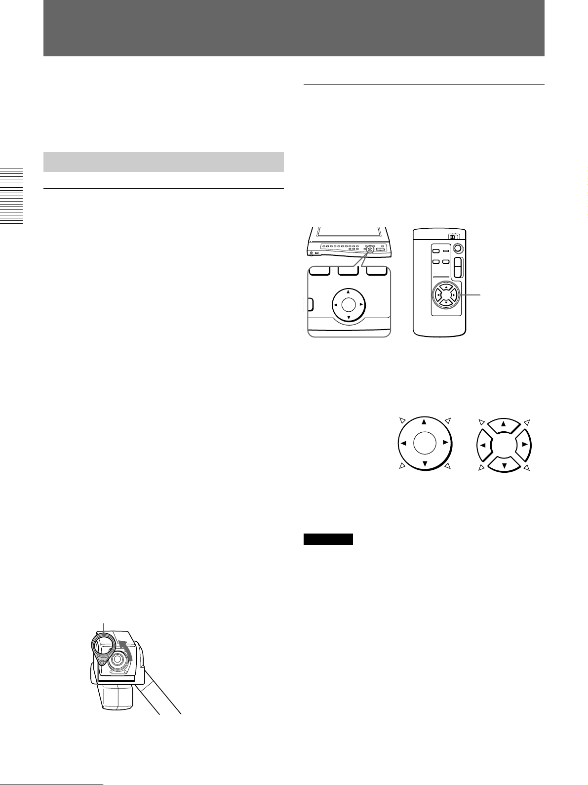
Pour changer l’angle de la caméra, appuyez sur les
touches CAMERA ANGLE du panneau de commande
ou de la télécommande. L’angle de la caméra peut être
réglé de 8 ou 4 directions à l’aide du commutateur BIT
du panneau arrière (page 44). Vous pouvez régler la
direction de la caméra pour les prises de vue vers
l’avant ou l’arrière.
T
W
CAMERA ANGLE
Touches
CAMERA ANGLE
Direction de l’angle de caméra
8 directions:4¢
4 directions:4
Touches CAMERA ANGLE
Sur le panneau
de commande
Sur la
télécommande
Le VID-P150 permet de réaliser des prises de vues
dans deux sens: la position pour documents pour les
prises de vue de sujets placés sur le plateau, la position
de basculement pour les sujets fixés au mur grâce à
une inclinaison manuelle à 90 degrés de la caméra.
Dans chaque position, vous pouvez déplacer la caméra
de gauche à droite ou de haut en bas à l’aide de la
fonction de déplacement motorisé. Cela vous permet
de réaliser des prises de vue et de présenter des images
de l’auditoire, des étudiants ou encore de vous-même.
Pour une prise de vue d’un sujet en mode de
basculement et éloigné du VID-P150, retirez la lentille
de plan rapproché.
Pour dégager la lentille de gros plan
Lentille de
gros plan
Faites
pivoter.
Sur la télécommande, appuyez sur deux touches
juxtaposées pour commander le déplacement dans la
diagonale voulue (¢direction)
Remarque
Si l’angle de la caméra ne se déplace pas en diagonale
ou si la caméra se déplace vers l’arrière, vérifiez le
réglage du commutateur BIT sur le panneau arrière
(page 44).
• CAMERA ANGLE est réglé sur OFF (4 WAY).
n Réglez-le sur ON (8 WAY).
• CAMERA DIRECTION est réglé sur OFF (REV).
n Réglez-le sur ON (STD).
Après utilisation, repositionnez la lentille de plan
rapproché.
38
Page 39
Pour repositionner l’angle de la caméra
FLIP-UP
DOCUMENT
Appuyez sur la touche HOME du panneau de
commande ou de la télécommande.
La touche HOME est opérante pour la position pour
documents et la position de basculement (page 42).
Touche HOME
T
W
HOME
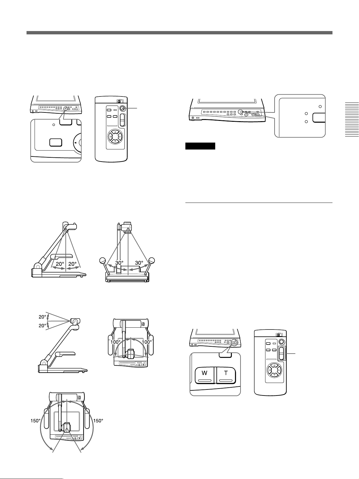
Plage de réglage de l’angle de la caméra
L’angle de la caméra peut être changé sur deux
positions. Pour un changement rapide, déplacez la
caméra manuellement.
Position du document
Position de basculement
Plage de fonctionnement automatique
DEL d’indication de position de la caméra
Pour les prises de vue sur le plateau, DOCUMENT
s’allume.
Le basculement manuel de la caméra de 90 degrés vers
le haut active l’indicateur FLIP-UP.
Remarque
Désactivez le mode de fonctionnement automatique
lorsque vous actionnez l’appareil manuellement. Le
déplacement ou l’arrêt forcés à la main de la caméra
alors qu’elle se trouve en mode automatique peut
provoquer un dysfonctionnement.
Zoomer l’image à l’écran (Touches ZOOM)
Pour réaliser un zoom avant ou arriére de l’image à
l’écran,utilisez les touches ZOOM du panneau de
commande.
Pour un zoom arrière de l’image pour de longues
prises de vue panoramiques, appuyez sur la touche W
(grand angle). Pour un zoom avant sur l’image pour
des gros plans, appuyez sur la touche T (téléobjectif).
Le VID-P150 offre deux vitesses de zoom. Sur le
panneau de commande, appuyez fermement sur la
touche pour un zoom à grande vitesse et plus
légèrement pour un zoom plus lent.
Sur la télécommande, maintenez les touches ZOOM
enfoncées pour un zoom à grande vitesse.
Plage de fonctionnement manuel
ZOOM
T
W
Touches ZOOM
39
Page 40
Opérations
Commutation de l’éclairage (Touche
LIGHTING)
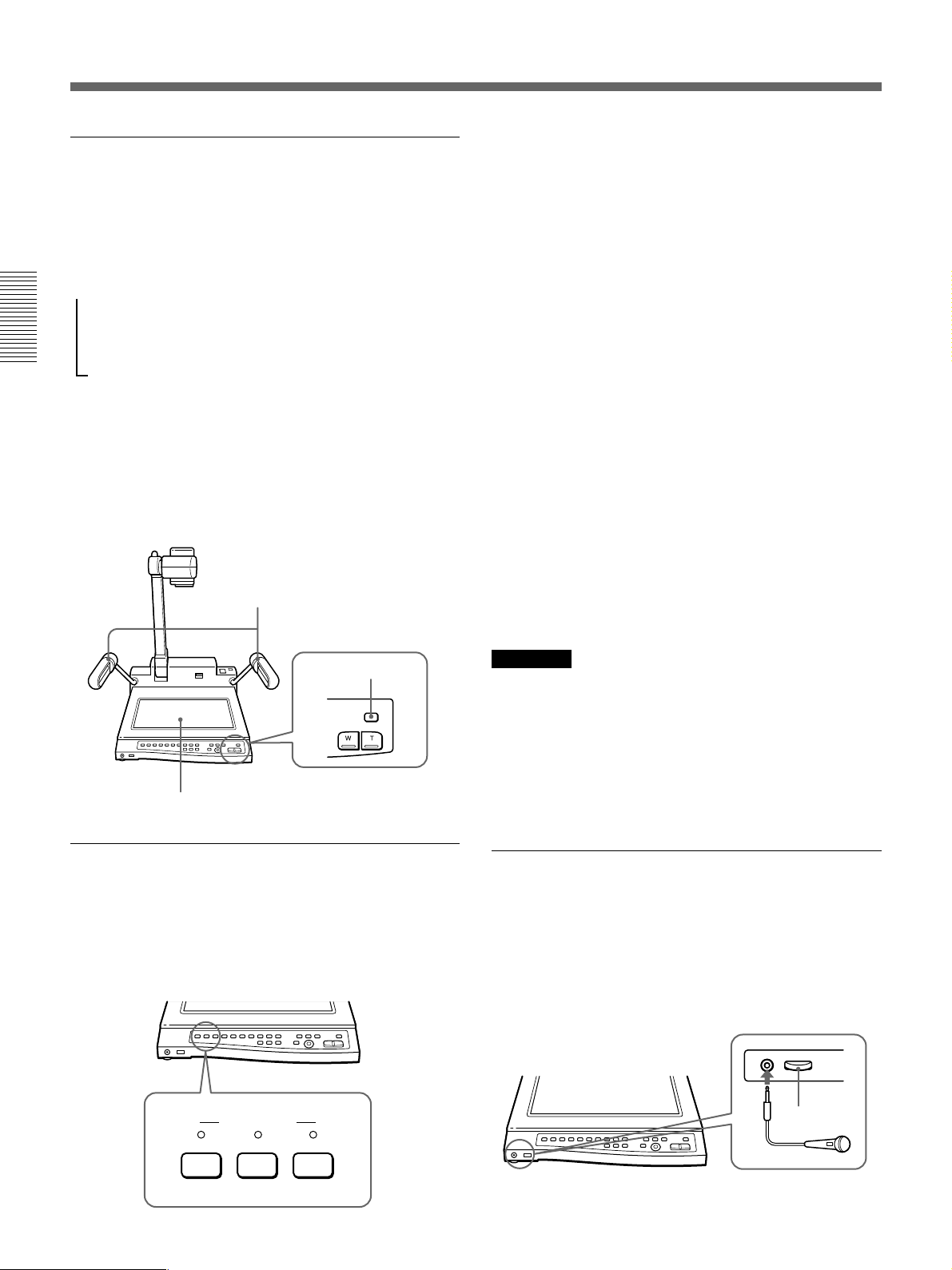
Les bras d’éclairage se mettent automatiquement sous
tension lorsque l’alimentation est commutée. Chaque
fois que vous appuyez sur la touche LIGHTING,
l’éclairage change selon la séquence suivante:
m
Les bras d’éclairage s’allument.
µ
Le rétro-éclairage s’allume.
µ
Tous les éclairages s’éteignent.
Lors de la prise de vue et de la visualisation de
transparents, de diapositives ou de films positifs,
appuyez sur la touche LIGHTING pour faire passer
l’éclairage des bras d’éclairage au rétro-éclairage.
Lorsque vous appuyez plusieurs fois de suite sur la
touche LICHTING, attendez une seconde avant
d'appuyer à nouveau sur la touche LIGHTING.
Bras d’éclairage
Pour sortir le signal vidéo de la caméra du
VID-P150 et le signal audio du microphone
raccordé au connecteur MIC
Appuyez sur la touche CAMERA. Le signal vidéo de
la caméra du VID-P150 et le signal audio du
microphone raccordé au connecteur MIC sont
automatiquement sortis.
A la mise sous tension, le signal vidéo de la caméra est
automatiquement sorti.
Pour sortir un signal de l’appareil vidéo
raccordé au VID-P150
Appuyez sur la touche VIDEO 1 ou VIDEO 2.
Les connecteurs VIDEO IN du panneau arrière sont
couplés aux touches VIDEO, le connecteur VIDEO IN
1 à la touche VIDEO 1 et le connecteur VIDEO IN 2 à
la touche VIDEO 2.
Lorsque le microphone est raccordé, cet appareil
diffuse le son en mixant le signal audio des
connecteurs AUDIO IN avec le signal audio du
microphone.
Pour passer du signal vidéo des connecteurs d'entrée
au signal vidéo de la caméra, appuyez sur la touche
CAMERA.
Touche LIGHTING
Rétro-éclairage
Sélection du signal de sortie (Touches
VIDEO OUT)
Les touches VIDEO OUT du panneau de commande
vous permettent de commuter les images de prise de
vue réalisées avec cet appareil et celles de l’appareil
vidéo raccordé.
VIDEO OUT
CAMERA
VIDEO 2VIDEO 1
Remarque
Si vous raccordez un appareil vidéo à la fois au
connecteur S VIDEO IN 1 et au connecteur VIDEO IN
1 du panneau arrière, le signal vidéo du connecteur S
VIDEO IN 1 est automatiquement sorti. Il en va de
même si vous établissez le raccordement à la fois au
connecteur VIDEO IN 2 et au connecteur S VIDEO IN
2.
Réglage du niveau du microphone
(Commande VOL)
Utilisez la commande VOL à l’avant du VID-P150
pour ajuster le niveau du microphone branché sur le
connecteur MIC. Tournez-le vers la droite pour
augmenter le volume. Tournez-le vers la gauche pour
baisser le volume.
MIC
Commande
VOL
Microphone
40
Page 41
Opérations avancées
Réglage de l’image selon vos préférences
Le VID-P150 règle automatiquement la mise au point,
le diaphragme et la balance des blancs lorsque vous
mettez le système sous tension et que vous placez
l’objet à visualiser au centre de l’écran. Vous pouvez
également régler ces paramètres manuellement.
Présélection de la mémoire de mode de
réglage (Touches PATTERN MEMORY)
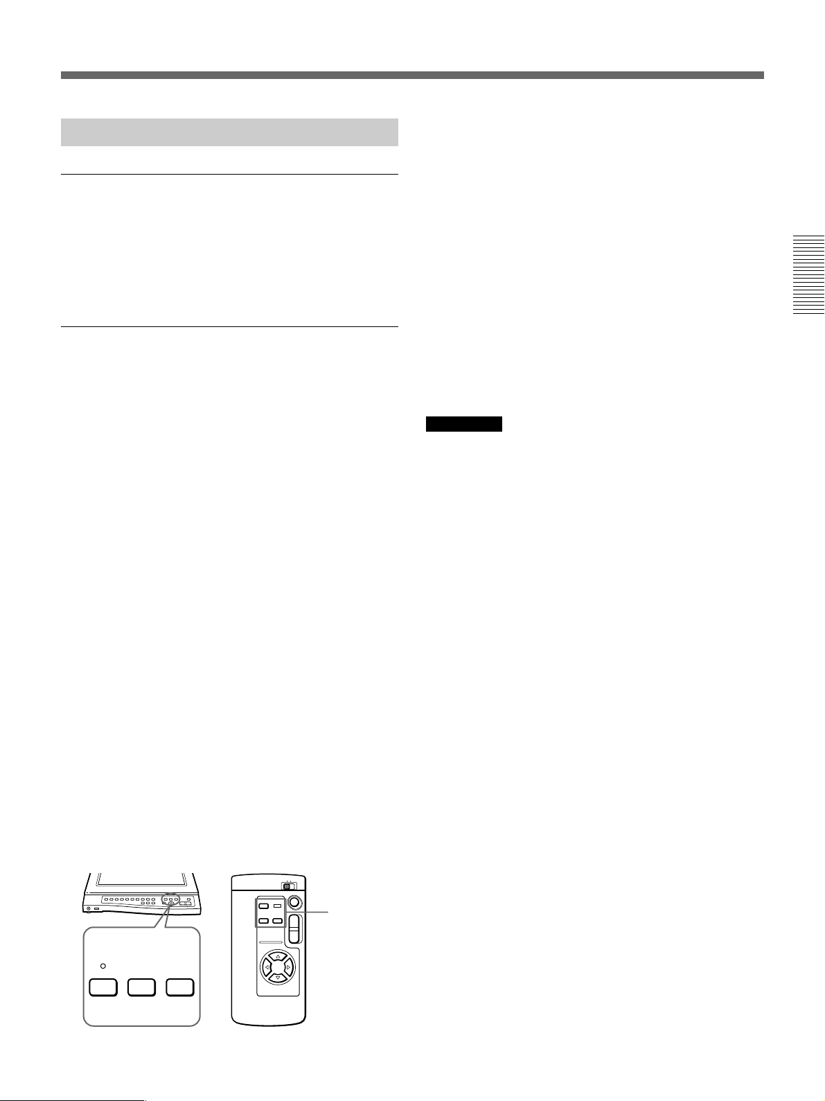
Les touches PATTERN MEMORY du panneau de
commande ou de la télécommande vous permettent de
présélectionner quatre modes de réglage, deux pour la
position pour documents et deux pour la position de
basculement. La fonction de mémoire de mode de
réglage mémorise l’angle de la caméra ainsi que les
réglages du zoom, de la mise au point, du diaphragme,
de la balance des blancs, de l’éclairage et d’effet (noir
& blanc, négatif). Si vous avez présélectionné un mode
de réglage pour un sujet que vous employez
fréquemment, vous pouvez le restaurer en appuyant
simplement sur la touche de présélection.
1 Ajustez l’angle de la caméra, le zoom, la mise au
point, le diaphragme, la balance des blancs,
l’éclairage et l’effet (noir & blanc, négatif).
2
Appuyez sur la touche PATTERN MEMORY SET.
3
Appuyez sur la touche PATTERN MEMORY 1 ou 2
pendant que l’indicateur PATTERN MEMORY SET
clignote rapidement (pendant environ 5 secondes).
L’indicateur PATTERN MEMORY SET s’allume
pendant environ 2 secondes et est ensuite
désactivé.
L’indicateur PATTERN MEMORY SET s’allume
pendant environ 2 secondes et puis s’éteint.
Lorsque vous utilisez la télécommande, un bip
sonore retentit.
Si le réglage n’a pas été correctement
mémorisé
Si l’indicateur PATTERN MEMORY SET ne s’allume
pas pendant environ 2 secondes ou si aucun bip sonore
ne retentit lorsque vous utilisez la télécommande, c’est
probablement parce que le réglage n’a pas été
correctement mémorisé. Dans ce cas, répétez les étapes
1 à 3.
Pour rappeler un réglage présélectionné
Pour rappeler un réglage de la position de documents,
amenez manuellement la caméra en position de
documents, et pour rappeler un réglage de la position
de basculement, amenez manuellement la caméra en
position de basculement, puis appuyez sur le bouton
PATTERN MEMORY 1 ou 2.
Remarques
• Si vous programmez un réglage PATTERN
MEMORY alors que la caméra se trouve en position
de basculement et que l’angle de la caméra se situe
en-dehors de la plage de fonctionnement
automatique, l’angle de la caméra se règle sur l’angle
le plus large possible de la plage de fonctionnement
automatique (100°) (page 39).
• Lorsque vous rappelez un réglage de la mémoire de
mode de réglage, la position peut ne pas exactement
être identique à celle qui a été programmée. Si
nécessaire, ajustez l’angle de la caméra.
• Lorsque vous mettez le système sous tension, ou si la
mémoire de mode de réglage n’a pas été
programmée, PATTERN MEMORY 1 ou 2 est le
réglage par défaut, à l’exception de la position de
repos.
• Le réglage que vous avez présélectionné sera
réinitialisé, si le système est mis hors tension.
PATTERN MEMORY
12SET
W
T
Touches
PATTERN
MEMORY
41
Page 42
Opérations
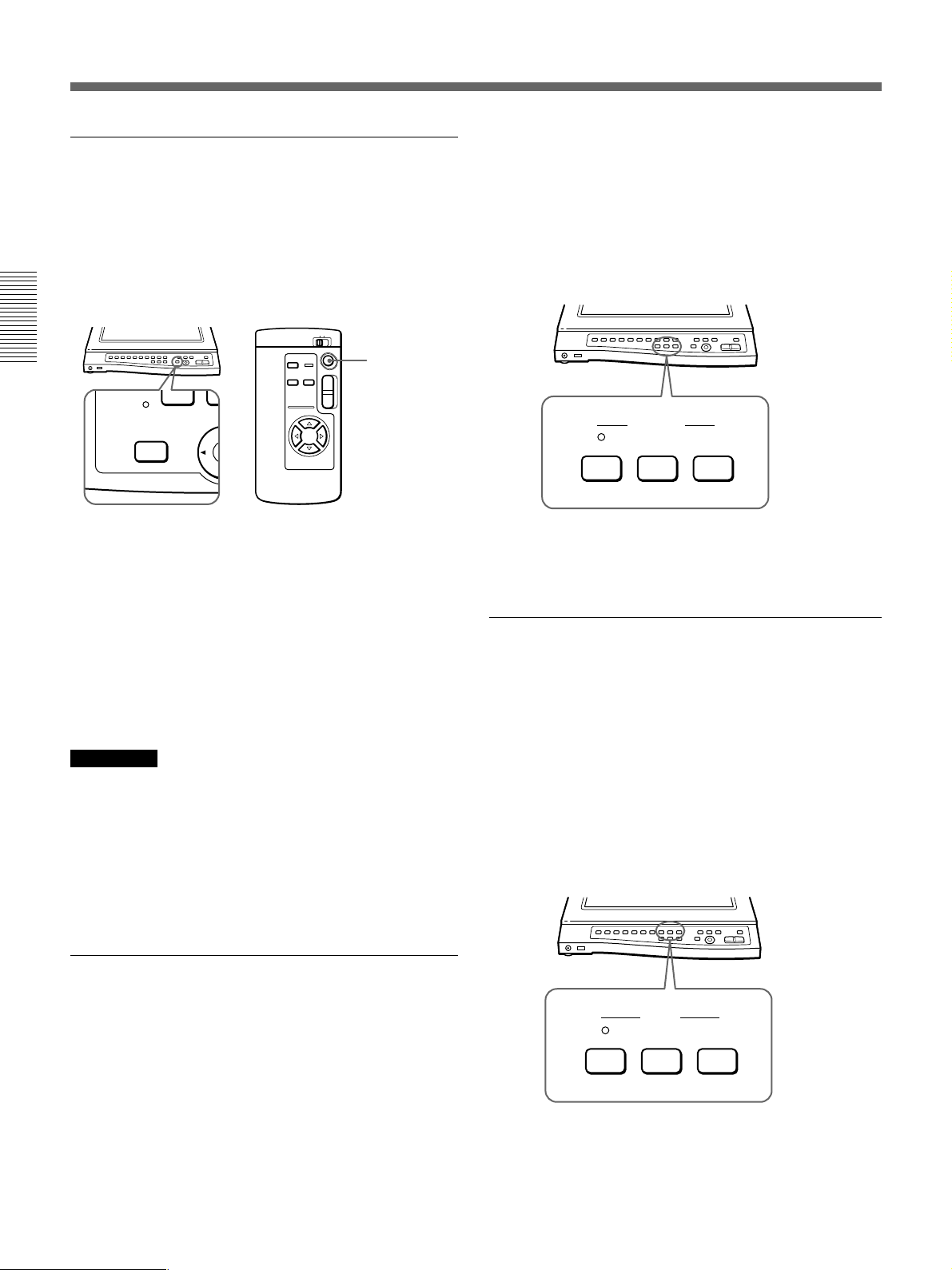
Retour à la position de départ
(Touche HOME)
Appuyez sur la touche HOME du panneau de
commande ou de la télécommande.
L’angle de la caméra et le zoom reviennent à l’angle
présélectionné et le réglage de la mise au point devient
automatique. La touche HOME est opérante pour la
position pour documents et la position de basculement.
Touche HOME
T
W
HOME
Changement de la position de repos
Vous pouvez changer l’angle de la caméra et zoom
pour la position que vous voulez régler. Tout en
maintenant la touche SET du panneau de commande
enfoncée, appuyez sur la touche HOME pendant 5
secondes. Lorsque vous avez terminé le réglage, un
bip retentit. Seul l’angle de la caméra et le zoom
peuvent être réglés à l’aide de la touche HOME.
Le réglage de la position de repos est conservé en
mémoire même si vous mettez le système hors
tension.
Remarques
•La position de repos (angle de la caméra et zoom) est
identique pour la position de documents et la position
de basculement. Si vous changez le réglage de la
position de repos dans la position de documents, le
réglage de la position de repos change également
pour la position de basculement.
•Vous ne pouvez pas changer le réglage de la position
de repos sur la télécommande.
Vous pouvez verrouiller la mise au point après qu’elle
a été réglée automatiquement. Appuyez une fois sur la
touche FAR ou NEAR pour verrouiller le réglage de la
mise au point.
Si vous changez l’angle de la caméra alors que la mise
au point est verrouillée, l’image ne sera pas nette. Dans
ce cas, activez le réglage automatique de la mise au
point.
FOCUS
NEAR FARAUTO
Pour revenir en mode de mise au point automatique
Appuyez sur la touche AUTO de façon à activer
l’indicateur AUTO.
Réglage manuel du diaphragme
(luminosité) (Touches IRIS)
Utilisez les touches IRIS du panneau de commande
pour régler le diaphragme (luminosité). Pour
augmenter la luminosité, appuyez sur la touche OPEN.
Pour diminuer la luminosité, appuyez sur la touche
CLOSE. Réglez le diaphragme manuellement lorsque
vous voulez visualiser :
•un objet qui réfléchit fortement la lumière et l’image
apparaît blanchâtre;
•un film négatif aux couleurs pâles;
•un contraste marqué.
Réglage manuel de la mise au point
(Touches FOCUS)
Utilisez les touches FOCUS du panneau de commande
pour régler la mise au point. Vous pouvez également
régler la mise au point pour un objet tridimensionnel
en utilisant les touches NEAR et FAR. Réglez la mise
au point manuellement lorsque vous visualisez :
•un objet comprenant de petits caractères ou de fins
motifs sur lesquels la mise au point pose des
difficultés;
•un objet faiblement contrasté;
•un objet tridimensionnel.
42
IRIS
CLOSE OPENAUTO
Pour revenir en mode de réglage automatique du
diaphragme
Appuyez sur la touche AUTO de façon à activer
l’indicateur AUTO.
Page 43
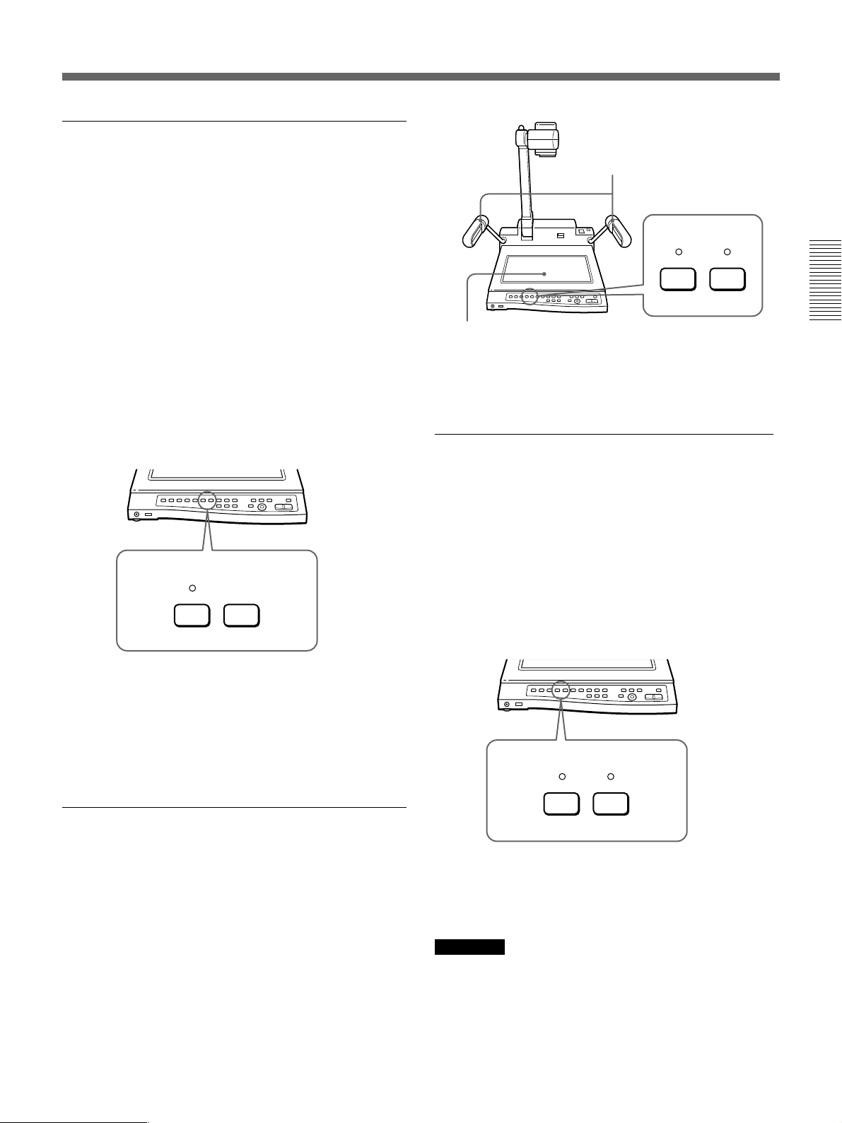
Verrouillage du réglage de la balance des
blancs (Touches W.BALANCE)
Le VID-P150 ajuste automatiquement la balance des
blancs. Vous pouvez verrouiller le réglage de la
balance des blancs si la couleur de l'objet affichée n'est
pas naturelle. Ceci est utile lorsque vous visualisez:
•un objet ou un arrière-plan monochrome (y compris
des films négatifs);
•un objet aux couleurs pâles.
Pour verrouiller le réglage de la balance des blancs,
appuyez sur la touche ONE PUSH. Le réglage de la
balance des blancs sélectionné juste avant que vous
n’appuyiez sur la touche est maintenu.
En mode ONE PUSH, le dernier réglage automatique
de la balance des blancs est verrouillé et est maintenu
même si les conditions d’éclairage changent. Cela
permet un affichage naturel des couleurs de l’objet
visualisé.
W.BALANCE
ONE PUSHAUTO
Bras d’éclairage
EFFECT
B&W NEGA
Rétro-éclairage
Pour visualiser un objet normal à l’écran
Appuyez sur la touche NEGA lorsque l’indicateur
NEGA est allumé. L’indicateur NEGA est désactivé
et les bras d’éclairage s’allument.
Réglage de l’écran en mode monochrome
(Touches EFFECT)
Pour régler l’écran en mode monochrome, appuyez
sur la touche B&W. L’indicateur B&W s’allume pour
indiquer que l’écran se trouve à présent en mode
monochrome. Nous vous recommandons de régler
l'écran en mode monochrome lorsque vous visualisez:
•un objet noir et blanc comme un document ou un
film noir et blanc;
•un objet comprenant de petits caractères comme un
article de journal ou encore un motif détaillé.
Pour revenir en mode de réglage automatique de la
balance des blancs
Appuyez sur la touche AUTO de façon à activer
l’indicateur AUTO lorsque vous changez l’objet de la
prise de vue, parce que les couleurs naturelles de
l’objet ne s’affichent pas en mode ONE PUSH. Le
VID-P150 déverrouille le réglage de la balance des
blancs et règle automatiquement la balance des blancs.
Visualisation de films négatifs
(Touches EFFECT)
Le VID-P150 se règle automatiquement pour la
visualisation d’objets normaux à l’écran lorsque vous
le mettez sous tension. Appuyez sur la touche NEGA
du panneau de commande pour afficher les films
négatifs. L’indicateur NEGA situé au-dessus de la
touche s’allume, les bras d’éclairage s’éteignent et le
rétro-éclairage s’allume. Le VID-P150 commence la
visualisation de l’image inversée des films négatifs.
Pour visualiser les films négatifs avec encore plus de
naturel, voir aussi la section “Verrouillage du réglage
de la balance des blancs (Touches W.BALANCE)” .
EFFECT
B&W NEGA
Pour activer l’écran en affichage couleur
Appuyez à nouveau sur la touche B&W. L’indicateur
B&W est désactivé et l’écran passe en mode
d’affichage couleur normal.
Remarque
Lors de la prise de vue et de la visualisation d’un
motif finement détaillé comme un article de journal, il
est conseillé de régler l’écran en mode d’affichage
monochrome et de raccorder un moniteur via le
connecteur S VIDEO OUT.
43
Page 44
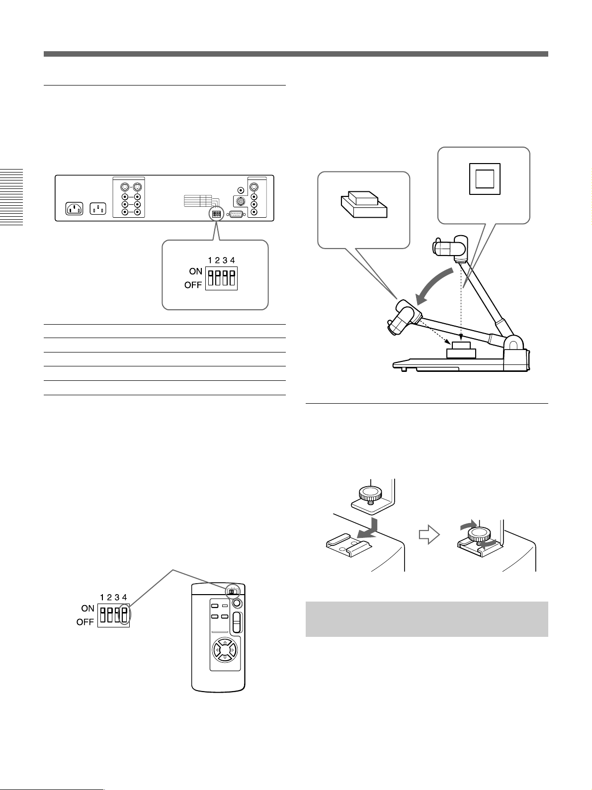
Opérations
Réglage de l’angle de la caméra et de la
télécommande (commutateur BIT)
Le commutateur BIT (réglage de l’angle de la caméra
et de la télécommande) peut être réglé de la façon
suivante, en fonction de vos besoins.
BIT SWITCH ONa) OFF
4 REMOTE COMMANDER 1 2
3 REMOTE CONTROL ON OFF
2 CAMERA DIRECTIONb) STD REV
1 CAMERA ANGLE 8-WAY 4-WAY
Prise de vue d’un objet tridimensionnel
Pour la prise de vue et la visualisation d’un objet
tridimensionnel, abaissez le support de caméra. Vous
pouvez également effectuer la prise de vue en oblique.
Prise de vue du
dessus
Prise de vue en
oblique
Abaissez le
support de
caméra.
a) Tous les commutateurs sont réglés par défaut sur ON.
b) STD (avant) lorsque la caméra se déplace dans la même
direction que les touches d’angle de la caméra.
REV (arrière) lorsque la caméra se déplace dans la
direction opposée aux touches d’angle de la caméra.
Numéro de la télécommande
Faites correspondre le numéro REMOTE
COMMANDER avec le commutateur BIT sur le
panneau arrière et le commutateur de numéro
REMOTE COMMANDER de la télécommande.
Pour faire correspondre le numéro
REMOTE COMMANDER
T
W
Utilisation du sabot porte-accessoire pour
un moniteur LCD
Cet appareil comporte un sabot porte-accessoire pour
la fixation d’un moniteur LCD.
Serrez la molette de
blocage.
Commande du VID-P150 depuis
un ordinateur
Vous pouvez commander le VID-P150 depuis un
ordinateur raccordé à un connecteur RS-232C. Le
logiciel requis pour commander le VID-P150 doit
cependant avoir été installé au préalable. Reportezvous au mode d’emploi de l’interface pour plus de
détails sur le protocole de communication de ce
logiciel.
44
Page 45

Spécifications
Système couleur Système couleur NTSC ou PAL
Dispositif de prise de vue
CCD (dispositif à couplage de charge)
à transfert et interligne de
1
/3"
Résolution Modèle NTSC
Horizontale: 460 lignes TV
Verticale: 350 lignes TV
Modèle PAL
Horizontale: 450 lignes TV
Verticale: 400 lignes TV
Eléments d’image 380.000, 768 × 494 (H/V)
(modèle NTSC)
440.000, 752 × 582 (modèle PAL)
Plage de prise de vue
Approx:350 × 260 mm
(13 7/8 × 10 1/4 po)
(grand angle)
Approx:31 × 23 mm (1 1/4 × 29/32 po)
(téléobjectif)
Objectif Zoom motorisé 12 ×
f = 5,4 à 64,8 mm (
7
/32 à 2 5/8 po)
F = 1,8 à 2,7
Zoom Commande électrique
(Deux vitesses de zoom)
Mise au point Commutable auto/manuelle
Diaphragme Commutable auto/manuel
Balance des blancs
Commutable auto/une pression (fixe)
Fonction de sélection de film positif/négatif
Possible
Fonction de sélection monochrome/couleur
Possible
Mémoire de mode de réglage 4 réglages (2 pour
l’angle de documents, 2 pour
l’angle de basculement)
Plage de déplacement de la caméra (automatique)
Angle document
Panoramique ±30°, Inclinaison ±20°
Angle de basculement
Panoramique ±100° (manuel ±150°)
Inclinaison ±20°
Vitesse de déplacement de la caméra
Panoramique/Inclinaison
Approximativement 6
°/seconde
(Change en fonction de la position
du zoom.)
Sélection du signal de sortie
Une sortie sur trois (CAMERA/
VIDEO1/VIDEO2)
Eclairage Bras d’éclairage: Double lampe
fluorescente 9 W × 2
Rétro-éclairage: Lampe
fluorescente 2,5 W à cathode
froide 2,5 W × 2
Connecteurs d'entrée
VIDEO IN (prise phono) (2)
1 Vp-p, 75 Ω, sync négative
S VIDEO IN (miniconnecteur DIN
à 4 broches) (2)
Y: 1 Vp-p, 75 Ω, sync négative
C: 0,286 Vp-p, 75 Ω
(modèle NTSC)
0,300 Vp-p, 75 Ω(modèle PAL)
AUDIO IN L/R (prises phono)
(2 chaque)
Impédance d’entrée: 47 kΩ
Niveau: –10 dB, asymétrique
Entrée MIC (prise standard) (1)
Impédance d’entrée: 3,3 kΩ
Niveau: –60 dB, asymétrique
Connecteurs de sortie
VIDEO OUT (type BNC) (1)
1 Vp-p, 75 Ω, sync négative
VIDEO OUT (prise phono) (1)
1 Vp-p, 75 Ω, sync négative
CAMERA MONITOR OUT
(prise phono) (1)
1 Vp-p, 75 Ω, sync négative
S VIDEO OUT (miniconnecteur
DIN à 4 broches) (1)
Y: 1 Vp-p, 75 Ω, sync négative
C: 0,286 Vp-p, 75 Ω
(modèle NTSC),
0,300 Vp-p, 75 Ω
(modèle PAL)
AUDIO OUT L/R (prises phono)
(1 chaque)
Impédance de sortie:
moins de 600 Ω
Niveau: –10 dB, asymétrique
Connecteur RS-232C
D-sub, 9 broches, mâle
Puissance de raccordement
120 V CA, 60 Hz (modèle NTSC)
230 V CA, 50/60 Hz (modèle PAL)
Sortie CA AC OUT (prise CA auxiliaire)
(modèle NTSC uniquement)
maximum 2,5 A/non commutée
Consommation électrique
120 V, 3 A (modèle NTSC)
230V, 0,3 A (modèle PAL),
Dimensions Après installation: Approx.
446 × 625 × 622 mm (l/h/p)
5
(17
/8 × 245/8 × 24 1/2 po)
Après démontage: Approx. 446 ×
190 × 711 mm (l/h/p)
5
(17
/8 × 71/2 × 28 po)
Masse Approx. 8,8 kg (19 lb 6 oz)
Accessoires fournis
Cordon d’alimentation (1)
Télécommande RMT-P150 (1)
Piles R6 (format AA) (2)
Mode d’emploi (1)
Mode d’emploi pour l’interface (1)
La conception et les spécifications sont sujettes à
modifications sans préavis.
45
Page 46

Deutsch
Table of contens
VORSICHT
Um Feuergefahr und die Gefahr eines elektrischen Schlages
zu vermeiden, darf das Gerät weder Regen noch
Feuchtigkeit ausgesetzt werden.
Um einen elektrischen Schlag zu vermeiden, darf das
Gehäuse nicht geöffnet werden. Überlassen Sie
Wartungsarbeiten stets nur qualifiziertem Fachpersonal.
Für Kunden in Deutschland
Dieses Produkt kann im kommerziellen und in begrenztem
Maße auch im industriellen Bereich eingesetzt werden. Dies
ist eine Einrichtung, welche die Funk-Entstörung nach
Klasse B besitzt.
46
Page 47

Inhalt
Einführung ....................................................................... 48
Eigenschaften ........................................................................48
Systemkonfiguration .............................................................50
Lage und Funktion der Teile und Bedienelemente ...... 52
Kamera und Bedienfeld ........................................................52
Rückseite...............................................................................53
Fernbedienung.......................................................................54
Vorbereitungen ................................................................ 55
Sicherheitsmaßnahmen .........................................................55
Vorbereiten der Fernbedienung ............................................55
Aufstellen des Geräts ............................................................55
Anschließen des Geräts an andere Geräte.............................56
Einstellen einzelner Geräteteile ............................................58
Zusammenlegen des Geräts ..................................................59
Betrieb .............................................................................. 60
Grundfunktionen ...................................................................60
Weitere Funktionen...............................................................63
Steuern der VID-P150 mit einem Computer.........................66
Technische Daten............................................................ 67
DE
Deutsch
47
Page 48
Einführung
Mit der Video-Präsentationsanlage VID-P150 können
Sie Materialien wie bedrucktes Papier, transparente
Blätter, Folien, Filmnegative und dreidimensionale
Gegenstände auf einem Farbmonitor oder einem
Projektor anzeigen, indem Sie sie mit einer
Farbvideokamera aufnehmen.
Darüber hinaus lassen sich die Kamerabewegungen bei
diesem Gerät mit der automatischen
Kamerapositionierung steuern.
Eigenschaften
Die VID-P150 zeichnet sich durch folgende
Eigenschaften und Funktionen aus.
Automatische Kamerapositionierung
Mit der automatischen Kamerapositionierung wird die
Kamera automatisch nach oben, unten, links und rechts
bewegt.
Sie können den Zoom (näher und weiter) einstellen
oder Material an einer Wand aufnehmen, indem Sie
die Kamera manuell um 90 Grad nach oben
schwenken (Flip-Up).
Scharfes Bild
Die 380.000 (NTSC-Modell) bzw. 440.000 (PAL-Modell)
Pixel der 1/3-Zoll-CCD-Aufnahmeeinheit ermöglichen
eine horizontale Auflösung von 460 Fernsehzeilen
(NTSC-Modell) bzw. 450 Fernsehzeilen (PAL-Modell), d.
h. ein hohes Bildschirmauflösungsvermögen. Über den
Anschluß S VIDEO OUT können Sie einen Monitor oder
Projektor anschließen, der mit einem Anschluß S VIDEO
IN ausgestattet ist. Dadurch können Sie eine noch höhere
Auflösung erzielen.
Einfaches Einstellen
Nach dem Einschalten schaltet sich die Seitenbeleuchtung
ein, und Schärfe, Blende und Weißabgleich stellen sich
automatisch ein. Sie können auch jede Einstellung von
Hand anpassen, je nach dem anzuzeigenden Bild.
Automatische Schnellfokussierlinse
Wenn Sie die innere Fokussierlinse benutzen, kann der
Fokus (Bildschärfe) in nur 1 bis 2 Sekunden eingestellt
werden.
Einfaches Anschließen
Wenn Sie Bilder anzeigen wollen, brauchen Sie
lediglich einen Farbmonitor anzuschließen, denn
Kamera, Objektiv, Beleuchtung und Stromversorgung
sind alle in einem Gerät integriert.
Drahtlose Fernbedienung
Mit der drahtlosen Fernbedienung können Sie die
Kamerabewegung (automatische
Kamerapositionierung oder Zoom) fernsteuern.
12fach-Motorzoom-Objektiv
Mit dem 12fach-Motorzoom-Objektiv dieses Geräts
können Sie verschiedene Materialien im
Größenbereich von 31 × 23 mm bis zu einem Blatt von
350 × 260 mm auf dem Bildschirm anzeigen.
Einstellungsspeicher
Sie können vier Mustereinstellungen, zwei für die
Dokumentenposition und zwei für die Flip-UpPosition, speichern. Bei dieser Funktion werden die
Einstellungen für Kamerawinkel, Zoom, Fokus,
Blende, Weißabgleich, Beleuchtung und Effekt
(schwarzweiß, negativ) gespeichert. Wenn Sie eine
Mustereinstellung aufrufen wollen, drücken Sie die
entsprechende Speichertaste.
48
Page 49

Abnehmbares Teleobjektiv
Verschiedene Ausgabemöglichkeiten
Wenn Sie die Kamera nach oben klappen, können Sie
das Teleobjektiv abnehmen, indem Sie es einfach drehen.
Aufnehmen und Wiedergeben
verschiedener Materialien
Verschiedene Materialien wie z. B. bedrucktes Papier
und transparente Blätter, aber auch Folien,
Filmnegative und dreidimensionale Gegenstände
können aufgenommen und wiedergegeben werden.
Wenn Sie Filmnegative aufnehmen und wiedergeben
wollen, müssen Sie nur die entsprechende Taste
drücken, um die Hintergrundbeleuchtung und die
Einstellung zum Anzeigen von Filmnegativen zu
aktivieren.
Integrierte Hintergrundbeleuchtung
Dank der großformatigen, integrierten
Hintergrundbeleuchtung können Sie A4-Objekte wie
z. B. transparente Blätter, Folien oder Filmnegative
aufnehmen und auf einem Monitor anzeigen. Zum
Einschalten der Hintergrundbeleuchtung genügt ein
Tastendruck.
Dieses Gerät verfügt über eine Y/C-Trennfunktion.
Damit können Sie das Videosignal über VIDEO OUT
oder S VIDEO OUT ausgeben, unabhängig davon, ob
das Videosignal über VIDEO IN oder S VIDEO IN
eingeht.
Externe Steuerung mit einem Computer
Dieses Gerät ist mit einer RS-232C-Schnittstelle
ausgestattet. Über diese Schnittstelle kann das Gerät
mit einem externen Computer gesteuert werden. Dazu
muß jedoch zunächst die Software zum Steuern der
VID-P150 installiert werden. In der Anleitung zur
Schnittstelle finden Sie weitere Einzelheiten zu den
Befehlen und dem Kommunikationsprotokoll dieser
Software.
Problemloser Transport
Das Gerät kann mühelos zusammengelegt werden und
wiegt so wenig, daß Sie es problemlos tragen und die
Präsentation an einem beliebigen Ort vorführen
können.
Integrierter Video-Wählschalter
Dieses Gerät verfügt über einen Video-Wählschalter.
Damit können Sie zwischen den mit diesem Gerät
aufgenommenen Bildern und den Bildern eines
angeschlossenen Videogeräts wie z. B. eines
Videorecorders oder Laserdisc-Players hin- und
herschalten.
Tonmischfunktion
Sie können Präsentationen live kommentieren, indem
Sie einfach ein Mikrofon und einen Monitor mit
Lautsprechern anschließen. Außerdem können
vorhandene Audiosignale mit dem Audiosignal des
angeschlossenen Mikrofons gemischt werden. Sie
können also Videosignale über den integrierten VideoWählschalter auf einem Monitor anzeigen und dabei
einen Kommentar hinzufügen.
Monitoranschluß
Dieses Gerät verfügt über einen Monitoranschluß, über
den die mit diesem Gerät aufgenommenen Bilder
ausgegeben werden. Wenn Sie den Monitoranschluß
mit einem Monitor verbinden, können Sie das Bild von
diesem Gerät anzeigen und gleichzeitig Videogeräte an
VIDEO1 oder VIDEO2 anschließen. Außerdem haben
Sie die Möglichkeit, die PATTERN MEMORYEinstellungen vorzunehmen.
Zubehörschuh für einen LCD-Monitor
(Flüssigkristallbildschirm)
Dieses Gerät ist mit einem Zubehörschuh ausgestattet,
mit dem Sie einen LCD-Monitor am Gerät anbringen
können. Wenn Sie einen LCD-Monitor am
Zubehörschuh anbringen, können Sie die Aufnahmen
bequem über diesen Monitor kontrollieren.
49
Page 50
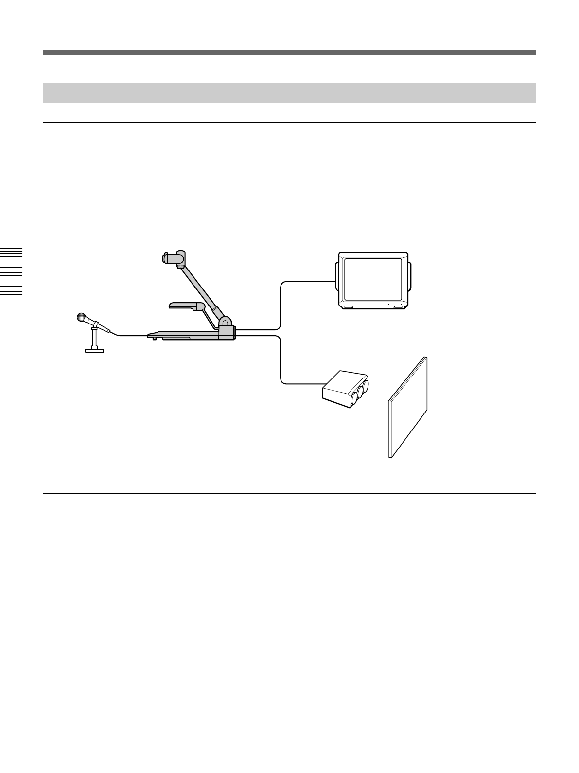
Einführung
Systemkonfiguration
Basiskonfiguration
Das Basissystem zum Vorführen einer Präsentation
oder Anzeigen von Lehrmaterialien setzt sich
folgendermaßen zusammen:
Farbmonitor mit Lautsprechern
Mikrofon
VID-P150
Projektor
Projektionsschirm
50
Page 51
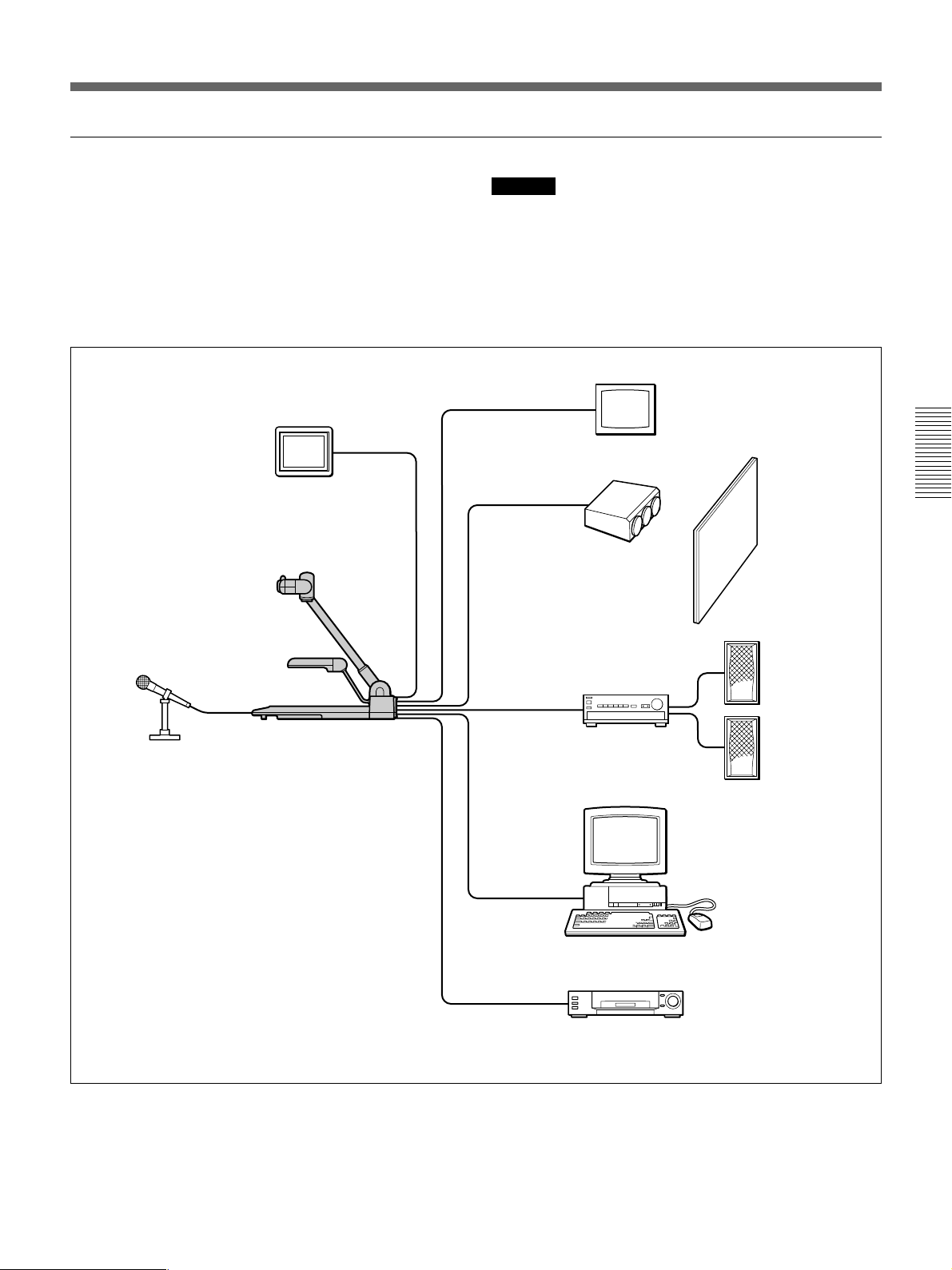
Erweitertes System
Wenn Sie ein Videogerät wie z. B. einen
Videorecorder oder Laserdisc-Player an dieses Gerät
anschließen, können Sie mit den VIDEO OUT-Tasten
zwischen dem Bild/Ton von diesem Gerät und vom
angeschlossenen Videogerät hin- und herschalten.
Wenn Sie einen Computer anschließen, können Sie die
VID-P150 über den Computer steuern.
Kameramonitor
Hinweis
Zum Steuern der VID-P150 mit einem Computer ist
eine spezielle Software erforderlich. Wie Sie mit
dieser Software arbeiten, erfahren Sie in der Anleitung
zur Schnittstelle.
Farbmonitor
Projektor
Projektionsschirm
Lautsprecher
Mikrofon
VID-P150
Verstärker
Computer
(zum Steuern der VID-P150)
Videogerät usw.
51
Page 52
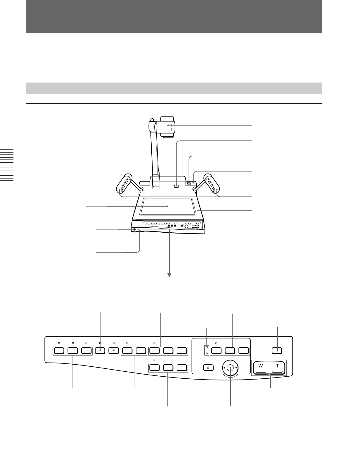
Lage und Funktion der Teile und Bedienelemente
Einzelheiten zu den jeweiligen Teilen und
Bedienelementen finden Sie auf den in Klammern
angegebenen Seiten.
Kamera und Bedienfeld
Kamera
Entriegelungshebel
UNLOCK (Seite 55)
Schalter POWER (Seite 60)
Zubehörschuh (Seite 66)
Seitenbeleuchtung
Hintergrundbeleuchtung
(Seite 62)
(Seite 58 und 62)
Ablagefläche
Anschluß MIC (Mikrofon)
(Seite 56 und 62)
Regler VOL
(Mikrofonlautstärke)
(Seite 56)
Taste B&W (Schwarzweiß)
(Seite 65)
VIDEO OUT
CAMERA
VIDEO 2 ONE PUSHVIDEO 1 B&W NEGA AUTO
VIDEO OUT-Tasten
(Videoausgang)
(Seite 62)
Taste NEGA (Negativ)
(Seite 65)
EFFECT W.BALANCE
W.BALANCE-Tasten
(Weißabgleich)
(Seite 65)
Bedienfeld
IRIS-Tasten (Seite 64)
LED-Anzeige für
Kameraposition (Seite 61)
IRIS
CLOSE OPENAUTO
FOCUS
NEAR FARAUTO
FOCUS-Tasten
(Seite 64)
PATTERN MEMORY-Tasten
(Seite 63)
PATTERN MEMORY
SET
FLIP-UP
DOCUMENT
CAMERA ANGLE
HOME
HOME-Taste
(Seite 61 und 64)
CAMERA ANGLE-Tasten
(Seite 60)
12
Taste LIGHTING
(Seite 62)
LIGHTING
ZOOM
ZOOM-Tasten (Seite 61)
52
Page 53
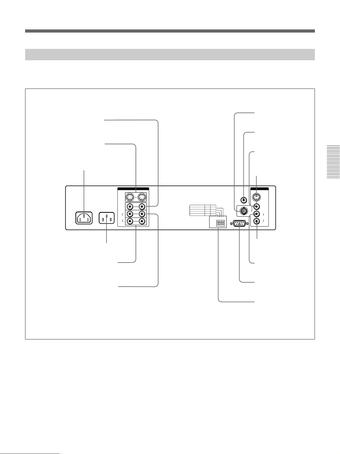
Rückseite
Einzelheiten zu den Anschlüssen finden Sie auf den
Seiten 56 und 57.
Anschlüsse VIDEO IN 1, 2
(Cinchbuchsen)
Anschlüsse S VIDEO IN 1, 2
(4polig, Mini-DIN)
Anschluß VIDEO OUT 2
(BNC-Ausgang)
Anschluß CAMERA
MONITOR (Cinchbuchse)
Anschluß VIDEO OUT 1
(Cinchbuchse)
Netzeingang AC IN
AC OUT
AC 120V 60Hz
AC IN
MAX 300W
UNSWITCHED
Buchse AC OUT (nur beim NTSC-Modell)
Anschlüsse AUDIO R IN 1, 2
(Cinchbuchsen)
Anschlüsse AUDIO L IN 1, 2
(Cinchbuchsen)
S VIDEO
VIDEO
AUDIO
VIDEO 1
L
R
Anschluß S VIDEO OUT
(4polig, Mini-DIN)
IN
VIDEO 2
1234
ON
OFF
CAMERA
MONITOR
RS-232C
OUT
S VIDEO
VIDEO 1
2
L
AUDIO
R
Anschluß AUDIO R OUT
(Cinchbuchse)
Anschluß AUDIO L OUT
(Cinchbuchse)
RS-232C-Anschluß
(D-Sub, 9polig, männlich)
BIT-Schalter (Schalter für
Kamerawinkel- und
Fernbedienungseinstellung)
(Seite 66)
53
Page 54
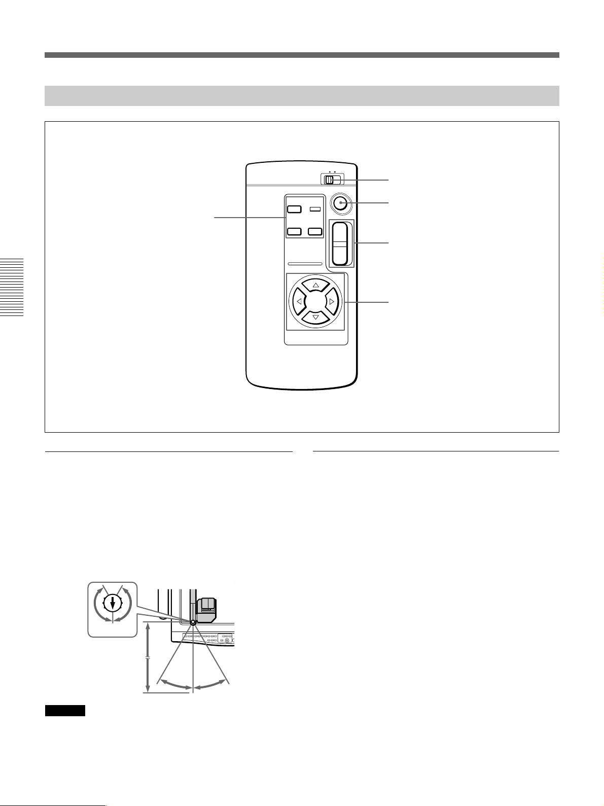
Lage und Funktion der Teile und Bedienelemente
Fernbedienung
1
2
HOME
SET
PATTERN MEMORY-Tasten (Seite 63)
1 2
PATTERN
MEMORY
CAMERA ANGLE
T
W
REMOTE COMMANDER-Zahlenschalter
(Seite 66)
Taste HOME (Seite 61 und 64)
ZOOM-Tasten (Seite 61)
CAMERA ANGLE-Tasten (Seite 60)
Reichweite der Fernbedienung
Die Reichweite der Fernbedienung beträgt 5 m bei
einem Winkel von 30 Grad nach beiden Seiten in
Richtung des weißen Pfeiles, der sich oben am
Fernbedienungssensor befindet. Der
Fernbedienungssensor kann von der Vorderseite dieses
Geräts her gesehen auf beide Seiten um 150 Grad
verschoben werden.
150°
150°
5 m
30°
30°
Hinweis
Achten Sie darauf, daß sich zwischen
Fernbedienungssensor und Fernbedienung kein
Hindernis befindet.
Überprüfen der Fernbedienung
Wenn die Fernbedienung nicht funktioniert,
überprüfen Sie bitte folgendes:
•Die Einstellung der BIT-Schalter an der Rückseite ist
falsch (Seite 66).
– REMOTE CONTROL ist auf OFF gestellt.
n Stellen Sie den Schalter auf ON.
– Die Zahl für REMOTE COMMANDER ist falsch.
n Stellen Sie die Zahl richtig ein.
•Die Batterien sind schwach.
n Tauschen Sie beide Batterien aus.
•Die Fernbedienung ist nicht auf den
Fernbedienungssensor gerichtet.
n Stellen Sie die Richtung.
54
Page 55
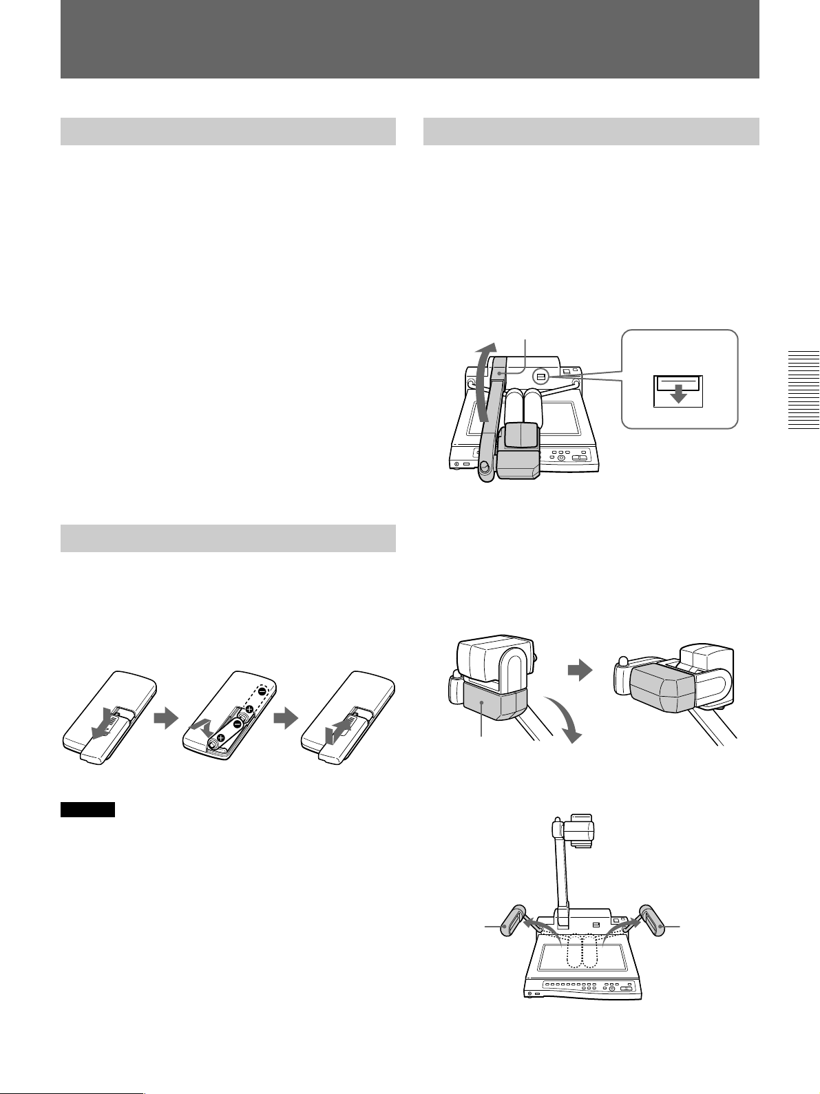
Vorbereitungen
Sicherheitsmaßnahmen
•Wenn Sie die VID-P150 längere Zeit nicht benutzen
wollen, ziehen Sie den Netzstecker aus der
Netzsteckdose. Ziehen Sie dabei immer am Stecker,
niemals am Kabel.
•Die Leuchtstoffröhren können bei Betrieb heiß
werden. Berühren Sie sie während des Betriebs und
beim Zusammenlegen der VID-P150 nicht.
•Reinigen Sie das Gehäuse mit einem weichen Tuch,
das Sie leicht mit einem milden Reinigungsmittel
angefeuchtet haben. Verwenden Sie auf keinen Fall
Lösungsmittel wie Alkohol oder Benzin. Diese
könnten die Oberfläche angreifen.
•Reinigen Sie das Objektiv mit einem Luftspray oder
einem weichen, trockenen Tuch, und achten Sie
darauf, die Oberfläche nicht zu zerkratzen.
•Wenn die Leuchtstoffröhren blinken oder dunkler
werden, sollten sie gegen neue ausgetauscht werden.
Wenden Sie sich in diesem Fall an Ihren SonyHändler.
Vorbereiten der Fernbedienung
Legen Sie zwei R6-Batterien (Größe AA) in das
Batteriefach der Fernbedienung ein. Achten Sie dabei
auf richtige Polarität: Plus- und Minus-Pol der
Batterien müssen den Markierungen im Batteriefach
entsprechen.
Aufstellen des Geräts
1 Halten Sie den Hebel UNLOCK nach unten
gedrückt, und heben Sie den Kameraständer nach
oben.
Wenn sich der Hebel UNLOCK nicht nach unten
drücken läßt, klappen Sie den Kameraständer nach
unten auf das Bedienfeld zu, bis er die
Ablagefläche berührt, und versuchen Sie dann
erneut, den Hebel UNLOCK nach unten zu
drücken.
Kameraständer
Hebel UNLOCK
2 Verschieben Sie die Kamera nach unten.
Wenn sich die Kamera in der Flip-Up-Position
befindet, verschieben Sie die Abdeckung von Hand
in Pfeilrichtung.
Wenn Sie das Gerät mit dem Schalter POWER
einschalten, kehrt das Kameraobjektiv in die
Ausgangsposition zurück.
Hinweis
Wenn die Batterien für die Fernbedienung schwach
sind, verringert sich die Reichweite der
Fernbedienung. Tauschen Sie in diesem Fall beide
Batterien aus.
Abdeckung
3 Klappen Sie die Seitenbeleuchtungen nach außen,
bis sie einrasten.
Seitenbeleuchtung
Seitenbeleuchtung
4 Schließen Sie das Netzkabel an den Anschluß AC
IN an der Rückseite an.
55
Page 56
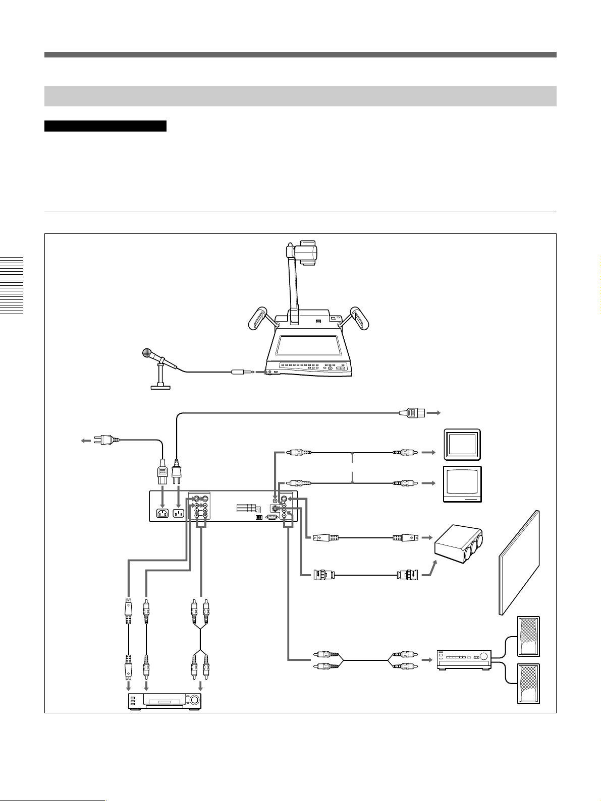
Vorbereitungen
Anschließen des Geräts an andere Geräte
Hinweise zum Anschließen
•Schalten Sie vor dem Anschließen die VID-P150 und
alle anderen anzuschließenden Geräte aus.
Anschlußbeispiel
Vorderseite
Mikrofon
MIC
Rückseite
Netzkabel (nicht mitgeliefert)
•Nur beim NTSC-Modell: Überprüfen Sie vor dem
Anschließen eines Geräts, z. B. eines Monitors, an
die Buchse AC OUT der VID-P150, ob die
Leistungsaufnahme maximal 2,5 A beträgt.
Schließen Sie kein Gerät an die VID-P150 an, bei
dem die Leistungsaufnahme mehr als 2,5 A beträgt.
VID-P150 (Vorderseite)
Netzeingang
Netzsteckdose
Netzkabel (mitgeliefert)
VID-P150
(Rückseite)
S VIDEO IN 1 oder 2
4poliges DIN-
a)
Kabel
S-Videoausgangsanschluß
AC IN
oder
VIDEO IN
1 oder 2
Videokabel
Videoausgangsanschluß
AC OUT (nur beim
NTSC-Modell)
AUDIO L, R
1 oder 2
Audiokabel
Audioausgangsanschlüsse
Videogerät
VIDEO OUT (Cinchbuchse)
Videokabel
VIDEO OUT 1
(Cinchbuchse)
S VIDEO OUT
(4poliges DIN)
4poliges DIN-Kabel
oder
Videokabel
VIDEO OUT 2
(BNC-Buchse)
Audiokabel
AUDIO L
und
R OUT
Audioeingangsanschlüsse
Videoeingangsanschluß
Videoeingangsanschluß
S-Videoeingangsanschluß
a)
Videoeingangsanschluß
Projektionsschirm
Kameramonitor
Farbmonitor
Projektor
Verstärker
Lautsprecher
a) Es empfiehlt sich, ein 4poliges DIN-Kabel zu verwenden,
wenn Sie dieses Gerät an ein Videogerät mit einem SVideoeingangs- oder -ausgangsanschluß anschließen.
56
Page 57

Anschlüsse für externe Steuerung mit einem Computer
Nehmen Sie zunächst die Anschlüsse wie auf der
vorherigen Seite erläutert und danach die unten
angegebenen Anschlüsse vor, wenn Sie dieses Gerät
über einen angeschlossenen Computer steuern wollen.
RS-232C-Kabel
VID-P150 (Rückseite)
RS-232C
(D-Sub, 9polig, männlich)
Hinweis
Zum Steuern der VID-P150 mit einem Computer ist
eine spezielle Software erforderlich. Wie Sie mit
dieser Software arbeiten, erfahren Sie in der Anleitung
zur Schnittstelle.
RS-232C-Anschluß
am Computer
57
Page 58
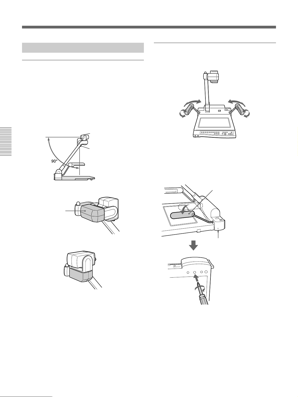
Vorbereitungen
Einstellen einzelner Geräteteile
Einstellen der Kamera
Mit der VID-P150 können Sie in zwei Positionen
aufnehmen: Die Dokumentenposition dient zum
Aufnehmen von Material auf der Ablagefläche, die
Flip-Up-Position zum Aufnehmen von Material an der
Wand. Dabei müssen Sie die Kamera manuell um 90
Grad nach oben schwenken.Verschieben Sie die
Abdeckung von Hand, um die Kamera ganz nach
Bedarf in die Dokumentenposition oder in die Flip-UpPosition zu bringen.
Flip-Up-Position
Dokumentenposition
Dokumentenposition
Einstellen der Seitenbeleuchtungen
Stellen Sie je nach Objekt den Winkel der Seitenbeleuchtungen
ein.
Wenn sich die Arme der Seitenbeleuchtungen lockern
Wenn die Arme nicht in ihrer Position bleiben, hat sich
wahrscheinlich die Schraube am Gehäuse gelockert.
Schalten Sie das Gerät am Schalter POWER aus, und ziehen
Sie die Schraube wie unten abgebildet an.
Der Arm läßt sich oben nicht
arretieren.
Abdeckung
Flip-Up-Position
Öffnung am Gehäuse
zum Einstellen der
Seitenbeleuchtungsarme
Ziehen Sie die Schraube
innen leicht (nicht zu fest) an.
Kreuzschlitzschraubenzieher
58
Page 59

Zusammenlegen des Geräts
Gehen Sie nach den Anweisungen unten vor, um die
VID-P150 zusammenzulegen, z. B. zum Transport.
4
Klappen Sie den Kameraständer vorsichtig nach
unten auf das Bedienfeld zu, bis er einrastet.
1 Drücken Sie die Taste HOME, um den
Kamerawinkel auf die voreingestellte Position
einzustellen (Seite 64). Wenn sich die Kamera in
der Flip-Up-Position befindet, verschieben Sie die
Abdeckung von Hand in die Dokumentenposition.
HOME
2 Schalten Sie das Gerät am Schalter POWER aus.
Kameraständer
Vorsicht
•Legen Sie das Gerät flach ab. Versuchen Sie nicht,
das Gerät auf die Rückseite zu legen oder auf der
Seite aufzustellen. Andernfalls kann das Gerät kippen
und fallen. Dabei kann es zu Schäden kommen, und
es besteht Verletzungsgefahr.
•Tragen Sie dieses Gerät nicht am Kameraständer.
Andernfalls kann es zu Fehlfunktionen kommen, und
es besteht Verletzungsgefahr.
FALSCH
FALSCH FALSCH
Schalter POWER
3 Klappen Sie beide Seitenbeleuchtungen nach unten
auf das Gehäuse.
Seitenbeleuchtungen
59
Page 60
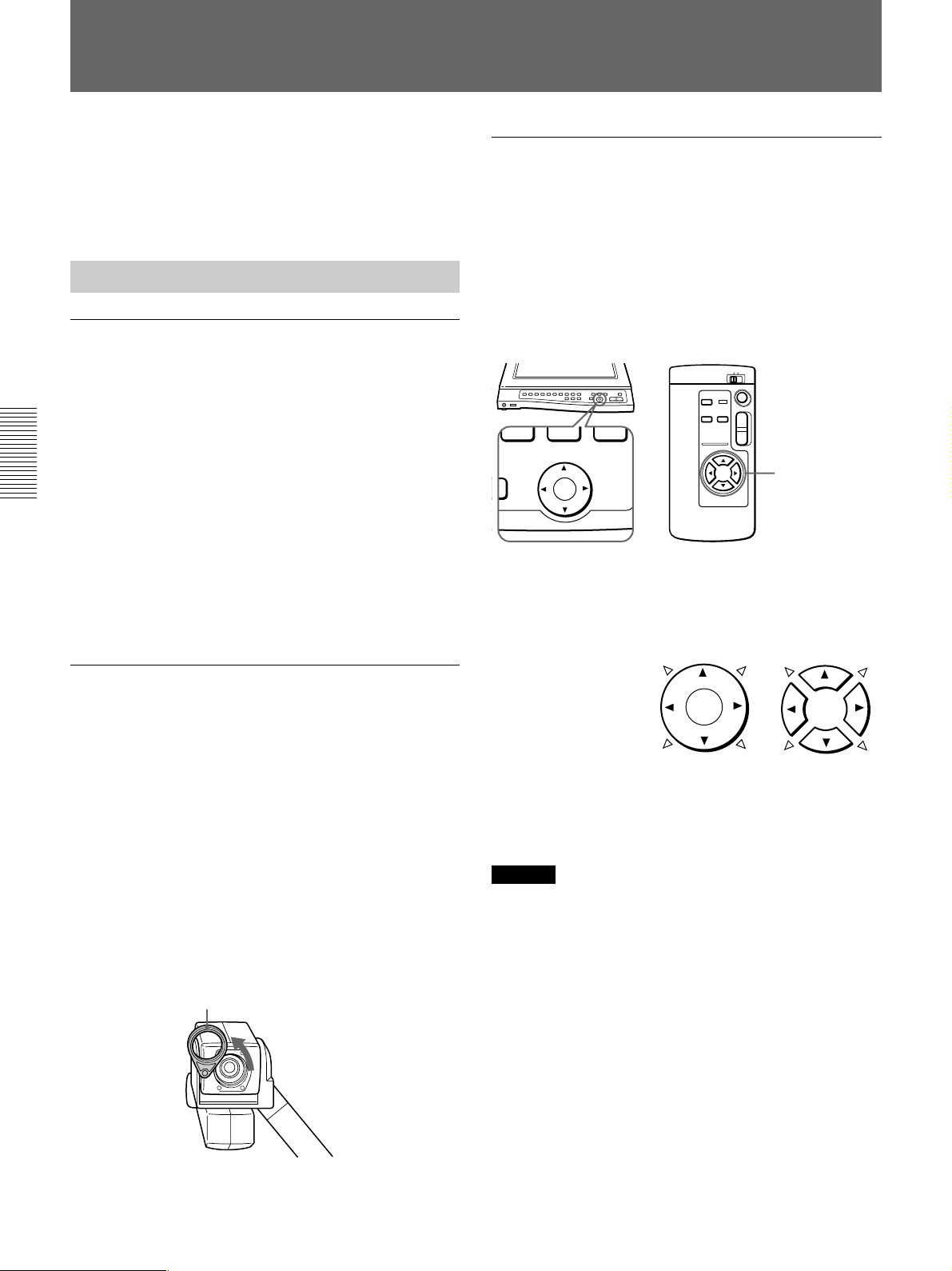
Betrieb
In diesem Abschnitt werden zum einen die
Grundfunktionen zum Aufnehmen und Wiedergeben
von normalen Materialien, zum anderen weitere
Funktionen zum Aufnehmen und Wiedergeben von
Spezialmaterialien, wie z. B. Filmnegativen, erläutert.
Grundfunktionen
Einschalten des Geräts (Schalter POWER)
Schalten Sie das Gerät mit dem Schalter POWER ein.
An der VID-P150 wird die Kamera automatisch an die
Ausgangsposition gestellt, die Seitenbeleuchtungen
schalten sich ein, und die Schärfe, die Blende
(Helligkeit) und der Weißwert werden eingestellt.
Während die Einstellungen vorgenommen werden, blinkt
die Anzeige CAMERA etwa 6 Sekunden lang, und die
ZOOM-, FOCUS-, IRIS- und W.BALANCE-Tasten
lassen sich nicht bedienen. Wenn der Einstellvorgang an
der VID-P150 zu Ende ist, leuchtet die Anzeige
CAMERA stetig, und Sie können das Gerät nun benutzen.
Dazu müssen Sie lediglich noch den Kamerawinkel
einstellen und das Bild auf dem Bildschirm vergrößern
oder verkleinern, so daß ein normales Dokument
angezeigt werden kann.
Einstellen des Kamerawinkels
(CAMERA ANGLE-Tasten)
Den Kamerawinkel ändern Sie mit den CAMERA
ANGLE-Tasten am Bedienfeld oder auf der
Fernbedienung. Mit der Einstellung der BIT-Schalter
(Seite 66) auf der Rückseite des Geräts wird festgelegt,
ob Sie 8 oder 4 Richtung haben, den Kamerawinkel
einzustellen. Sie können die Kamerarichtung für
Aufnahmen nach vorne oder nach hinten einstellen.
T
W
CAMERA ANGLE
-
Richtung des Kamerawinkels
8 Richtung: 4¢
4 Richtung: 4
CAMERA ANGLE-Tasten
Am
Bedienfeld
CAMERA ANGLETasten
Auf der
Fernbedienung
Wechseln der Kamerarichtung
Mit der VID-P150 können Sie in zwei Positionen
aufnehmen: Die Dokumentenposition dient zum
Aufnehmen von Material auf der Ablagefläche, die
Flip-Up-Position zum Aufnehmen von Material an der
Wand. Dabei müssen Sie die Kamera manuell um 90
Grad nach oben schwenken. In beiden Positionen
können Sie die Kamera mit der automatischen
Kamerapositionierung von links nach rechts bzw. nach
oben oder unten bewegen. Dies ermöglicht es Ihnen,
das Publikum, die Schüler oder sich selbst
aufzunehmen und anzuzeigen. Um im Flip-Up-Winkel
ein weit von der VID-P150 entferntes Objekt
aufzunehmen, nehmen Sie das Teleobjektiv ab.
So nehmen Sie das Teleobjektiv ab
Teleobjektiv
Drehen
Auf der Fernbedienung drücken Sie jeweils die beiden
nebeneinanderliegenden Tasten, um den
Kamerawinkel in die entsprechende Richtung
(Richtung ¢) diagonal zu verschieben.
Hinweis
Wenn sich der Kamerawinkel nicht diagonal
verschiebt oder die Kamera nach hinten zeigt,
überprüfen Sie die Einstellung der BIT-Schalter auf
der Rückseite (Seite 66).
•CAMERA ANGLE ist auf OFF gestellt (4 WAY).
n Stellen Sie den Schalter auf ON (8 WAY).
•CAMERA DIRECTION ist auf OFF gestellt (REV).
n Stellen Sie den Schalter auf ON (STD).
Bringen Sie das Teleobjektiv nach dem Aufnehmen
wieder an.
60
Page 61

So setzen Sie den Kamerawinkel zurück
Drücken Sie die Taste HOME am Bedienfeld oder auf
der Fernbedienung.
Die Taste HOME funktioniert in der Dokumenten- und
in der Flip-Up-Position (Seite 64).
LED-Anzeige für Kameraposition
Wenn Sie Objekte auf der Ablagefläche aufnehmen,
leuchtet die Anzeige DOCUMENT.
Wenn Sie die Kamera manuell um 90 Grad nach oben
schwenken, beginnt FLIP-UP zu leuchten.
Taste HOME
T
W
HOME
Mögliche Kamerawinkel
Der Kamerawinkel läßt sich in beiden Positionen
wechseln.
Wenn Sie die Kamera schnell bewegen wollen,
bewegen Sie sie von Hand.
Dokumentenposition
Flip-Up-Position
Bereich für automatische Einstellung
FLIP-UP
DOCUMENT
Hinweis
Schalten Sie die Automatik aus, wenn Sie die Kamera
von Hand bewegen wollen. Wenn die Automatik
eingeschaltet ist und Sie die Kamera von Hand
bewegen oder stoppen, kann es zu Fehlfunktionen
kommen.
Vergrößern bzw. Verkleinern des Bildes
auf dem Bildschirm (ZOOM-Tasten)
Sie können das Bild auf dem Bildschirm mit den
ZOOM-Tasten auf dem Bedienfeld vergrößern bzw.
verkleinern (Zoom-Funktion).
Für einen Zoom weg von der Vorlage
(Panoramaaufnahme) drücken Sie die Taste W
(Weitwinkel). Für einen Zoom auf ein Detail der
Vorlage (Nahaufnahme) drücken Sie die Taste T
(Telefoto).
Die VID-P150 bietet zwei unterschiedliche ZoomGeschwindigkeiten. Drücken Sie die Taste am
Bedienfeld fest für einen schnellen Zoom und leicht
für einen langsameren Zoom.
Auf der Fernbedienung halten Sie die Tasten ZOOM
für einen schnellen Zoom gedrückt.
Bereich für manuelle Einstellung
ZOOM
T
W
ZOOM-Tasten
61
Page 62

Betrieb
Wechseln der Beleuchtung (Taste LIGHTING)
Beim Einschalten des Geräts schaltet sich automatisch
die Seitenbeleuchtung ein. Mit jedem Tastendruck auf
LIGHTING wechselt die Beleuchtung folgendermaßen.
Die Seitenbeleuchtung schaltet sich ein.
m
µ
Die Hintergrundbeleuchtung schaltet sich ein.
µ
Die Beleuchtung schaltet sich ganz aus.
Beim Aufnehmen und Anzeigen von transparenten
Materialien wie Folien, Dias und Filmpositiven drücken
Sie die Taste LIGHTING, um von der Seitenbeleuchtung
zur Hintergrundbeleuchtung umzuschalten.
Wenn Sie die Taste LIGHTING mehrmals drücken
wollen, warten Sie immer 1 Sekunde, bevor Sie die
Taste erneut drücken.
Seitenbeleuchtungen
So geben Sie das Videosignal der Kamera der
VID-P150 und das Audiosignal des am
Anschluß MIC angeschlossenen Mikrofons aus
Drücken Sie die Taste CAMERA. Das Videosignal der
Kamera der VID-P150 und das Audiosignal des
Mikrofons am Anschluß MIC werden automatisch
ausgegeben.
Wenn Sie das Gerät einschalten, wird automatisch das
Videosignal von der Kamera ausgegeben.
So geben Sie das Signal des an die VID-P150
angeschlossenen Videogeräts aus
Drücken Sie die Taste VIDEO 1 oder VIDEO 2.
Die VIDEO IN-Anschlüsse an der Rückseite sind an
die VIDEO-Tasten gekoppelt, d. h. der Anschluß
VIDEO IN 1 an die Taste VIDEO 1 und der Anschluß
VIDEO IN 2 an die Taste VIDEO 2.
Wenn ein Mikrofon angeschlossen ist, mischt das
Gerät das Audiosignal von den AUDIO INAnschlüssen mit dem Audiosignal vom Mikrofon.
Wenn Sie von dem über die Eingänge eingespeisten
Videosignal zum Videosignal von der Kamera
wechseln wollen, drücken Sie die Taste CAMERA.
Taste LIGHTING
Hintergrundbeleuchtung
Auswählen des Ausgangssignals
(VIDEO OUT-Tasten)
Mit den VIDEO OUT-Tasten am Bedienfeld können
Sie zwischen den mit diesem Gerät aufgenommenen
Bildern und den Bildern vom angeschlossenen
Videogerät hin- und herschalten.
VIDEO OUT
CAMERA
VIDEO 2VIDEO 1
Hinweis
Wenn Sie ein Videogerät an die Buchse S VIDEO IN
1 und an die Buchse VIDEO IN 1 an der Rückseite
angeschlossen haben, wird automatisch das
Videosignal der Buchse S VIDEO IN 1 ausgegeben.
Entsprechend wird das Signal der Buchse S VIDEO IN
2 ausgegeben, wenn Sie an VIDEO IN 2 und an S
VIDEO IN 2 ein Gerät angeschlossen haben.
Einstellen des Mikrofonpegels
(Regler VOL)
Stellen Sie den Pegel des Mikrofons, das an den
Anschluß MIC angeschlossen ist, mit dem Regler
VOL an der Vorderseite der VID-P150 ein. Drehen Sie
den Regler nach rechts, um die Lautstärke zu erhöhen,
oder nach links, um sie zu verringern.
MIC
Regler VOL
Mikrofon
62
Page 63
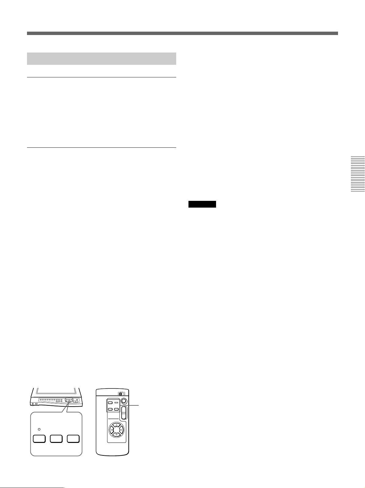
Weitere Funktionen
Einstellen des Bildes
Die VID-P150 stellt automatisch Schärfe, Blende und
Weißwert ein, wenn Sie das Gerät einschalten und das
anzuzeigende Material in die Mitte des Bildschirms
positionieren. Sie können die Einstellungen aber nach
Belieben auch von Hand vornehmen.
Speichern von Einstellungen
(PATTERN MEMORY-Tasten)
Mit den PATTERN MEMORY-Tasten am Bedienfeld
oder auf der Fernbedienung können Sie vier
Mustereinstellungen speichern, zwei für die
Dokumentenposition und zwei für die Flip-UpPosition. Bei dieser Funktion werden die Einstellungen
für Kamerawinkel, Zoom, Fokus, Blende,
Weißabgleich, Beleuchtung und Effekt (schwarzweiß,
negativ) gespeichert. Wenn Sie die Einstellungen für
ein Objekt, das Sie häufig anzeigen, gespeichert haben,
brauchen Sie zum Abrufen der Einstellungen nur die
entsprechende Speichertaste zu drücken.
1 Nehmen Sie die Einstellungen für Kamerawinkel,
Zoom, Fokus, Blende, Weißabgleich, Beleuchtung
und Effekt (schwarzweiß, negativ) vor.
2
Drücken Sie die Taste PATTERN MEMORY SET.
3
Drücken Sie die Taste PATTERN MEMORY 1 oder
2, solange die Anzeige PATTERN MEMORY SET
schnell blinkt (etwa 5 Sekunden lang).
Die Anzeige PATTERN MEMORY SET leuchtet
etwa 2 Sekunden lang und erlischt dann.
Die Anzeige PATTERN MEMORY SET leuchtet
etwa 2 Sekunden lang und erlischt dann. Wenn Sie
die Fernbedienung verwenden, ist ein Signalton zu
hören.
Wenn die Einstellung nicht korrekt
gespeichert wurde
Wenn die Anzeige PATTERN MEMORY SET nicht
für etwa 2 Sekunden aufleuchtet bzw. kein Signalton
zu hören ist, wenn Sie die Fernbedienung benutzen,
wurde die Einstellung unter Umständen nicht korrekt
gespeichert. Führen Sie in diesem Fall Schritt 1 bis 3
erneut aus.
So rufen Sie die gespeicherten Einstellungen
ab
Zum Abrufen der Einstellung für die
Dokumentenposition stellen Sie die Kamera von Hand
in die Dokumentenposition, zum Abrufen der
Einstellung für die Flip-Up-Position stellen Sie die
Kamera von Hand in die Flip-Up-Position. Drücken
Sie anschließend die Taste PATTERN MEMORY 1
oder 2.
Hinweise
• Wenn Sie die PATTERN MEMORY-Einstellung
vornehmen, während sich die Kamera in der Flip-UpPosition befindet und der Kamerawinkel außerhalb
des Bereichs für die automatische Einstellung liegt,
wird die Kamera auf den weitesten Winkel
eingestellt, der im automatischen Einstellbereich
möglich ist (100°) (Seite 61).
•Wenn Sie die PATTERN MEMORY-Einstellung
wieder aufrufen, ist die Position unter Umständen
etwas anders als ursprünglich eingestellt. Korrigieren
Sie gegebenenfalls den Kamerawinkel.
•Wenn Sie das Gerät einschalten oder wenn keine
PATTERN MEMORY-Einstellung vorgenommen
wurde, gelten mit Ausnahme der Einstellung für die
Ausgangsposition für PATTERN MEMORY 1 oder 2
die werkseitigen Einstellungen.
•Die gespeicherten Einstellungen werden
zurückgesetzt, wenn Sie das Gerät ausschalten.
PATTERN MEMORY
12SET
PATTERN
T
MEMORY-Tasten
W
63
Page 64
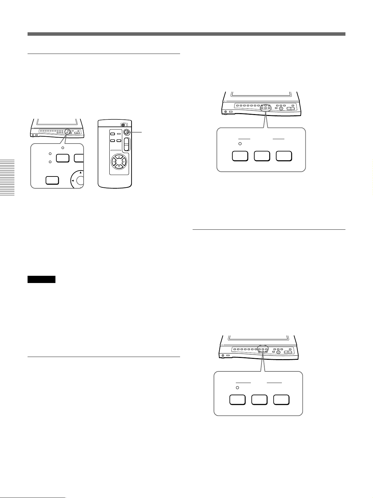
Betrieb
Zurückfahren in die Ausgangsposition
(Taste HOME)
Drücken Sie die Taste HOME am Bedienfeld oder auf
der Fernbedienung. Kamerawinkel und Zoom werden
auf den voreingestellten Winkel gesetzt, der Autofokus
wird aktiviert. Die Taste HOME funktioniert in der
Dokumenten- und in der Flip-Up-Position.
Taste HOME
T
SET
HOME
Ändern der Einstellung für die Ausgangsposition
Sie können Kamerawinkel und Zoom für die
gewünschte Position ändern. Halten Sie die Taste SET
am Bedienfeld gedrückt, und drücken Sie die Taste
HOME 5 Sekunden lang. Wenn die Einstellung
beendet ist, ertönt ein Signalton.
Mit der Taste HOME können Sie nur Kamerawinkel
und Zoom einstellen.
Die Einstellung für die Ausgangsposition wird
beibehalten, auch wenn Sie das Gerät ausschalten.
Hinweise
•Die Ausgangsposition (Kamerawinkel und Zoom) ist
in der Dokumenten- und der Flip-Up-Position
identisch. Wenn Sie die Einstellung für die
Ausgangsposition in der Dokumentenposition ändern,
ändert sich auch die Einstellung für die
Ausgangsposition in der Flip-Up-Position.
•Über die Fernbedienung läßt sich die Einstellung für
die Ausgangsposition nicht ändern.
W
Wenn Sie den Kamerawinkel ändern, während der
Fokus fest eingestellt ist, wird das Bild unscharf.
Schalten Sie in diesem Fall zur automatischen
Fokuseinstellung.
FOCUS
NEAR FARAUTO
So shalten Sie wieder zur automatischen
Fokuseinstellung
Drücken Sie die Taste AUTO, so daß die Anzeige
AUTO leuchtet.
Einstellen der Blende (Helligkeit) von
Hand (IRIS-Tasten)
Stellen Sie die Blende (Helligkeit) mit den IRISTasten am Bedienfeld ein. Zum Erhöhen der Helligkeit
drücken Sie die Taste OPEN, zum Verringern die
Taste CLOSE. Stellen Sie die Blende manuell ein,
wenn Sie folgendes anzeigen wollen:
•ein Objekt, das Licht stark reflektiert (Bild ist sehr
hell),
•ein Filmnegativ mit blassen Farben oder
•Material mit starkem Kontrast.
Einstellen der Schärfe von Hand
(FOCUS-Tasten)
Stellen Sie die Schärfe (den Fokus) mit den FOCUSTasten am Bedienfeld ein. Mit den Tasten NEAR und
FAR können Sie auch einen dreidimensionalen
Gegenstand fokussieren. Stellen Sie die Schärfe
manuell ein, wenn Sie folgendes anzeigen wollen:
•Material mit kleiner Schrift oder feinem Muster, das
sich schwer fokussieren läßt,
•Material mit schwachem Kontrast oder
•dreidimensionale Gegenstände.
Sie können den Fokus fest einstellen, wenn er
automatisch eingestellt wurde. Drücken Sie dazu
einmal die Taste FAR oder NEAR.
64
IRIS
CLOSE OPENAUTO
So schalten Sie wieder zur automatischen
Blendeneinstellung
Drücken Sie die Taste AUTO, so daß die Anzeige
AUTO leuchtet.
Page 65

Festeinstellen des Weißwerts
(W.BALANCE-Tasten)
Die VID-P150 stellt automatisch den Weißwert ein.
Sie können den Weißwert fest einstellen, wenn die
Farben des Objekts nicht natürlich angezeigt werden.
Dies kann der Fall sein, wenn Sie folgendes anzeigen:
•schwarzweißes Material (einschließlich
Filmnegative) bzw. schwarzweißer Hintergrund oder
•Material mit blassen Farben.
Zum Festeinstellen des Weißwerts drücken Sie die
Taste ONE PUSH. Der Weißwert, der unmittelbar vor
dem Drücken der Taste eingestellt wurde, wird
beibehalten.
Im Modus ONE PUSH wird der zuletzt automatisch
ermittelte Weißwert beibehalten, auch wenn sich die
Lichtverhältnisse ändern. Dadurch kann das Material
in seinen natürlichen Farben angezeigt werden.
W.BALANCE
ONE PUSHAUTO
So wechseln Sie wieder zum automatischen
Weißabgleich
Drücken Sie die Taste AUTO, so daß die Anzeige
AUTO leuchtet, wenn Sie das aufzunehmende Objekt
wechseln oder wenn die Farben des Materials im
Modus ONE PUSH nicht natürlich angezeigt werden.
Die VID-P150 hebt die Festeinstellung des Weißwerts
auf und stellt ihn automatisch ein.
Seitenbeleuchtungen
EFFECT
B&W NEGA
Hintergrundbeleuchtung
So können Sie wieder normales Material auf dem
Bildschirm anzeigen
Drücken Sie die Taste NEGA, wenn die Anzeige
NEGA leuchtet. Die Anzeige NEGA erlischt, und die
Seitenbeleuchtung schaltet sich ein.
Einstellen des Schwarzweißmodus für den
Bildschirm (EFFECT-Tasten)
Wenn Sie für den Bildschirm den Schwarzweißmodus
einstellen wollen, drücken Sie die Taste B&W. Die
Anzeige B&W leuchtet auf, d. h. der Bildschirm
befindet sich nun im Schwarzweißmodus. Es empfiehlt
sich, für den Bildschirm den Schwarzweißmodus
einzustellen, wenn Sie folgendes anzeigen wollen:
•schwarzweißes Material, z. B. eine schwarzweiße
Vorlage oder einen Schwarzweißfilm, oder
•Material mit kleiner Schrift (z. B. Zeitung) und feinen
Mustern.
Anzeigen von Filmnegativen
(EFFECT-Tasten)
Die VID-P150 ist automatisch so eingestellt, daß nach
dem Einschalten normale Materialien auf dem
Bildschirm angezeigt werden können. Drücken Sie die
Taste NEGA auf dem Bedienfeld, wenn Sie
Filmnegative anzeigen wollen. Die Anzeige NEGA
über der Taste leuchtet, die Seitenbeleuchtung schaltet
sich aus, und die Hintergrundbeleuchtung schaltet sich
ein. Die VID-P150 zeigt das Umkehrbild der
Filmnegative an.
Wie Sie Filmnegative am natürlichsten anzeigen
können, schlagen Sie bitte auch unter “Festeinstellen
des Weißwerts (W.BALANCE-Tasten)” nach.
EFFECT
B&W NEGA
So wechseln Sie wieder in den Farbmodus
Drücken Sie erneut die Taste B&W. Die Anzeige
B&W erlischt, und der Bildschirm befindet sich
wieder im normalen Farbmodus.
Hinweis
Wenn Sie ein feines Muster wie z. B. eine
Zeitungsspalte aufnehmen und anzeigen wollen,
empfiehlt es sich, den Bildschirm in den
Schwarzweißmodus zu schalten und einen Monitor an
den Anschluß S VIDEO OUT anzuschließen.
65
Page 66
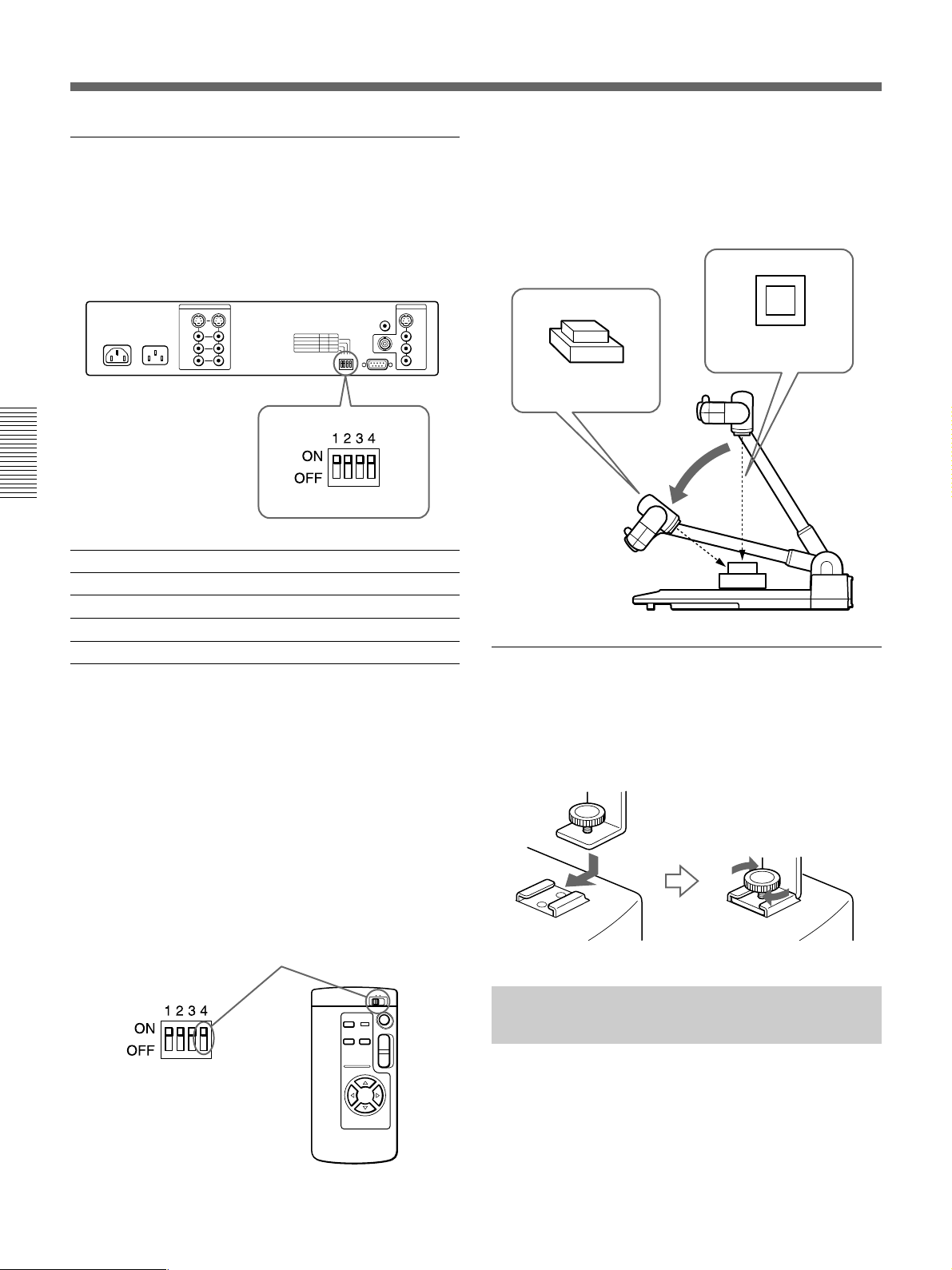
Betrieb
Einstellung für Kamerawinkel und
Fernbedienung (BIT-Schalter)
Im folgenden ist die Funktion der BIT-Schalter
(Schalter zum Einstellen von Kamerawinkel und
Fernbedienung) aufgeführt. Stellen Sie die Schalter auf
Ihre Erfordernisse ein.
BIT Schealter ONa) OFF
4 REMOTE COMMANDER 1 2
3 REMOTE CONTROL ON OFF
2 CAMERA DIRECTIONb) STD REV
1 CAMERA ANGLE 8-WAY 4-WAY
a) Alle Schalter sind werkseitig auf ON gestellt.
b) STD (vorwärts) bedeutet, daß sich die Kamera in dieselbe
Richtung wie die CAMERA ANGLE-Tasten bewegt. Bei
REV (rückwärts) bewegt sich die Kamera in die andere
Richtung.
So nehmen Sie ein dreidimensionales Objekt
auf
Zum Aufnehmen und Anzeigen eines dreidimensionalen
Objekts senken Sie den Kameraständer. Sie können das
Objekt auch in einem bestimmten Winkel aufnehmen.
Nehmen Sie das
Objekt von oben auf.
Nehmen Sie das Objekt
in einem bestimmten
Winkel auf.
Senken Sie den
Kameraständer.
Verwenden des Zubehörschuhs für einen
LCD-Monitor
Dieses Gerät ist mit einem Zubehörschuh ausgestattet,
mit dem Sie einen LCD-Monitor am Gerät anbringen
können.
Die Fernbedienungsnummer
Sorgen Sie dafür, daß die Zahl für REMOTE
COMMANDER an den BIT-Schaltern auf der
Geräterückeite mit der Zahl am REMOTE
COMMANDER-Schalter auf der Fernbedienung
übereinstimmt.
Übereinstimmende Zahl für
REMOTE COMMANDER
T
W
66
Ziehen Sie den
Sperrknopf an.
Steuern der VID-P150 mit einem Computer
Sie können die VID-P150 mit einem Computer
steuern, der an den RS-232C-Anschluß angeschlossen
ist. Dazu muß jedoch zunächst die Software zum
Steuern der VID-P150 installiert werden. In der
Anleitung zur Schnittstelle finden Sie weitere
Einzelheiten zum Kommunikationsprotokoll dieser
Software.
Page 67

Technische Daten
Farbsystem NTSC oder PAL
Sensorelement
Auflösung NTSC-Modell
Bildelemente 380.000, 768 × 494 (H/V) (NTSC-
Aufnahmebereich ca.350 × 260 mm (bei Weitwinkel)
Objektiv 12fach-Motorzoom-Objektiv
Zoom mit elektrischem Antrieb
Fokus Automatisch/manuell einstellbar
Blende Automatisch/manuell einstellbar
Weißwert Automatisch einstellbar/fester Wert
Positiv-/Negativfilmauswahlfunktion
Schwarzweiß-/Farbauswahlfunktion
PATTERN MEMORY 4 Einstellungen (2 für
Kamerabewegungsbereich (automatisch)
Kamerabewegungsgeschwindigkeit
Ausgangssignal wählbar
Beleuchtung Seitenbeleuchtung: 9-W-
Eingänge VIDEO IN (Cinchbuchse) (2)
1
/3-Zoll-CCD (Charge Coupled
Device) mit
Zwischenzeilentransferverfahren
Horizontal: 460 Fernsehzeilen
Vertikal: 350 Fernsehzeilen
PAL-Modell
Horizontal: 450 Fernsehzeilen
Vertikal: 400 Fernsehzeilen
Modell)
440.000, 752 × 582 (PAL-Modell)
ca.31 × 23 mm (bei
Nahaufnahmen)
f = 5,4 bis 64,8 mm
F = 1,8 bis 2,7
(zwei Zoom-Geschwindigkeiten)
Möglich
Möglich
Dokumentenwinkel,
2 für Flip-Up-Winkel)
Winkel bei Dokumentenposition
Schwenken ±30°, Neigen ±20°
Winkel bei Flip-Up-Position
Schwenken ±100° (manuell ±150°)
Neigen ±20°
Schwenken/Neigen mit etwa 6°/
Sekunde (je nach Zoom-Position)
Drei Ausgänge (CAMERA/
VIDEO1/VIDEO2)
Zwillingsleuchtstoffröhre × 2
Hintergrundbeleuchtung: 2,5-W-
Kaltkathodenleuchtstoffröhre × 2
1 Vp-p, 75 Ω, sync-negativ
S VIDEO IN (4polig, Mini-DIN)
(2)
Y: 1 Vp-p, 75 Ω, sync-negativ
C: 0,286 Vp-p, 75 Ω
(NTSC-Modell),
0,300 Vp-p, 75 Ω
(PAL-Modell)
AUDIO IN (L/R) (Cinchbuchsen)
(je 2)
Eingangsimpedanz: 47 kΩ
Pegel: –10 dB, unsymmetrisch
Eingang MIC (Cinchbuchsen) (1)
Eingangsimpedanz: 3,3 kΩ
Pegel: –60 dB, unsymmetrisch
Ausgänge VIDEO OUT (BNC-Anschluß) (1)
1 Vp-p, 75 Ω, sync-negativ
VIDEO OUT (Cinchbuchsen) (1)
1 Vp-p, 75 Ω, sync-negativ
CAMERA MONITOR OUT
(Cinchbuchse) (1)
1 Vp-p, 75 Ω, sync-negativ
S VIDEO OUT (4polig, Mini-DIN)
(1)
Y: 1 Vp-p, 75 Ω, sync-negativ
C: 0,286 Vp-p, 75 Ω
(NTSC-Modell),
0,300 Vp-p, 75 Ω
(PAL-Modell)
AUDIO OUT (L/R)
(Cinchbuchsen)
(je 1)
Ausgangsimpedanz:
weniger als 600 Ω
Pegel: –10 dB, unsymmetrisch
RS-232C-Anschluß
D-Sub, 9polig, männlich
Betriebsspannung
120 V Wechselstrom, 60 Hz
(NTSC-Modell)
230 V Wechselstrom, 50/60 Hz
(PAL-Modell)
Netzausgang AC OUT
(Hilfswechselstromausgang) (nur
beim NTSC-Modell)
max. 2,5 A, ohne Umschaltung
Leistungsaufnahme
120 V, 3 A (NTSC-Modell)
230V, 0,3 A (PAL-Modell)
Abmessungen Aufgestellt: ca. 446 × 625 × 622
mm (B/H/T)
Zusammengelegt: ca. 446 × 190 ×
711 mm (B/H/T)
Gewicht ca. 8,8 kg
Mitgeliefertes Zubehör
Netzkabel (1)
Fernbedienung RMT-P150(1)
R6-Batterien (Größe AA)(2)
Bedienungsanleitung (1)
Anleitung zur Schnittstelle (1)
Änderungen, die dem technischen Fortschritt dienen,
bleiben vorbehalten.
67
Page 68
Sony Corporation Printed in Japan
68
 Loading...