

Page 1

1.MS-1-D.1
Chapter 1. Disassembly & Assembly Guide
1-3. Disassembly & Assembly
- Main Section -
MS-1 Main Section Disassembly
Confidential
X505 Series
Page 2
1.MS-1-D.2
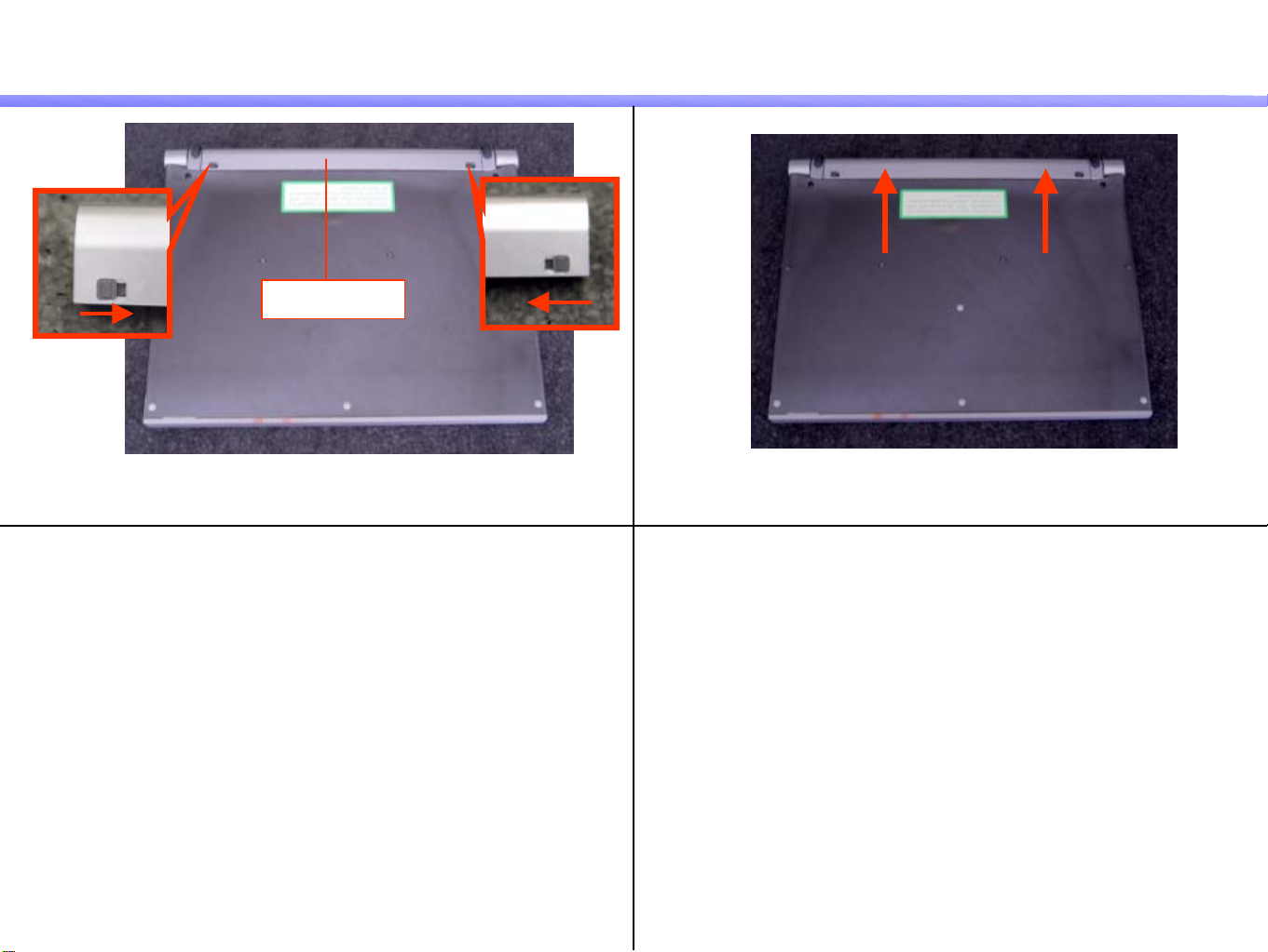
Battery Pack
Confidential
1)
2)
Battery Pack
Slide the Levers toward the cen t er. In the state 1), pull the Battery Pack in the arrow direction.
X505 Series
Page 3

1.MS-1-D.3
Dummy Card
Confidential
1)
3)
Eject Lever
Put the Main Section with its left side toward you.
2)
First time Second time
Push the Eject Lever twice.
Pull out the Dummy Card.
X505 Series
Page 4

1.MS-1-D.4
Confidential
Cap (Hinge)
* If not disassembling the LCD Section, this work is not required.
1)
Cap
Widen the Detents (at three locations) outward with a bamboo skewer
to remove.
Remarks
DC Jack side Power Button side
2)
Remove the Cap (at two locations) by sliding a s it is outward.
<Detent positions>
X505 Series
Page 5

1.MS-1-D.5
Stopper (Hinge)
Confidential
1)
3)
Foot
Peel off the Foot (at two locations).
2)
Screw : B4
Screw:
1st Model - B5(
2
[MA]
B4
Remove the Screws (two locations).
*In the 1st Models, the types of Screw differ
between the left and the right.
Special Screw)
[CHG]
5
Release the Stopper (at two locations).
*The Detents in the near side are fit.
Raise them forward and pull out.
Stopper
X505 Series
Page 6

1.MS-1-D.6
Cover (Hinge)
Confidential
1)
Cover
Widen the Detents (at two locations) with a bamboo skewer outward
to remove.
* The Covers may be easily broken. Work with care.
Remarks
2)
In the state 1), slide the Cover (two locations) to remove.
Detent positions
LCD SideLCD side
X505 Series
Page 7

1.MS-1-D.7
Confidential
Housing (Bottom)-1
1)
Peel off the Foot (at six locations).
* Give a care not to damage the Housing (Bottom).
* Two kinds of Foot are provided.
3) 4)
Screw : B6
* Also refer to the next page.
2)
Open the Main Section till the LCD Section and the Bottom Section
are in the right angle.
Screw : B4
Remove the Screws (two locations) from the left side of the Main Section.
Remove the Screws (two locations) from the back face of the Main Section.
X505 Series
Page 8

1.MS-1-D.8
Housing (Bottom)-2
Confidential
5)
Work desk
LCD Section
Place the Main Section on the work desk as shown in the picture.
*Work with a great care not to fall the Main Section
or to damage the LCD!
7) 8)
Housing (Bottom)
6)
Screw : B5 (X4) , B3 (X4), B4(X2), B2 (X1)
B5
B5
B5
B5
B4
B4
B3
B3
B3
B3
B2
Remove the eleven Screws from the bottom of the Main Section.
* The Screws B3 and B5 are the special screws.
Detent
Detent
Raise the Housing (Bottom) at its near side.
*Release the Detents (two locations) by pushing the
Palmrest lightly toward the center.
Remove the Housing (Bottom) by pulling it toward you.
* The back side is inserted in the Palmrest.
X505 Series
Page 9

1.MS-1-D.9
LCD Section
Confidential
1)
Cover (Harness)
Disconnect the Harness (at three locations) in the order from A to C.
Remove the Cover (one location).
* Take out the Harness from under the Mother Board and pull it to remove.
3) 4)
FPC
2)
(A: LCD Harness/ B: Harness (INV) / C: Harness (DC) )
A
C
B
Screw : B4
Disconnect the Harness (PWR) (one location).
*Take out the Harness from under the FPC and pull it in the
arrow direction.
Remove the one Screw and remove the LCD Section.
*Work with great care not to damage the LCD Section!
* The Protect (Harness) may be displaced from the Hinge (Le ft).
X505 Series
Page 10

1.MS-1-D.10
HDD
Confidential
1)
Remark 1
Cushion
FPC
Disconnect the FPC (at two locations).
* Pull it upward to disconnect.
FPC
2)
Remark 2
Pull the HDD in the arrow direction to remove.
FPC
Gasket
Sheet
The above parts are installed on the HDD.
* Be careful not to bend the Pin when disconnecting the FPC.
X505 Series
Page 11

1.MS-1-D.11
PC Card Connector
Confidential
1)
3)
1st Model
Harness (Speaker)
Peel off the attachment (one location) and disconnect
the Harness (one location).
1st Models: Sheet
Other : Tape
Connector positions
2
[MA]
2)
Screw : B4
Remove the two Screws.
FPC
PC Card Connector
Disconnect the FPC and then remove the PC Card Connector.
Pull the Connector Section upward to disconnect.
X505 Series
Page 12

1.MS-1-D.12
PC Card Connector Block
Confidential
1)
3)
PC Card Eject
Push the Detents (two locations) in the arrow direction and
remove the PC Card Eject.
Screw : B4
2)
Sheet
Peel off the Sheet (one location).
Screw
Plate
Remove the two Screws and remove the Plate.
X505 Series
Page 13

1.MS-1-D.13
FPC-8
1)
Remove the Screws (at one location) and remove the FPC.
Confidential
Screw : B6
FPC-8
X505 Series
Page 14

1.MS-1-D.14
Confidential
Mother Board-1
1)
FPC (Keyboard)
Disconnect the FPC (Keyboard).
* Raise the lock (brown color) of the Connector forward to release the lock.
3) 4)
* Also refer to the next page.
2)
FPC
Disconnect the FPC (Pointing Device).
* Pull the FPC as it is in the arrow direction.
FPC
Disconnect the FPC (LED).
*Slide the lock (black color) of the Connector in the arrow direction
to release the lock.
Ring
Remove the Ring (one location).
X505 Series
Page 15

1.MS-1-D.15
Mother Board-2
Confidential
5)
Screw : B4
Mother Board
Remove the two Screws and remove the Mother Board.
Remarks
1st Model
Sheet
* Sheet may possibly be peeled off.
Do not lose the Sheet.
2
[MA]
X505 Series
Page 16

1.MS-1-D.16
FPC
Confidential
1)
3)
FPC
Peel off the Tape (at one location).
FPC
Tape
2)
From the 2nd Models
[MA]
2
Peel off the Tape (at one location).
5
[ADD]
Tape
Release the Detents (at two locations) and disconnect the FPC.
X505 Series
Page 17

1.MS-1-D.17
Keyboard
Confidential
1)
3)
Screw :B7
Remove the Screw (one location).
Keyboard
2)
Part A
ボス
Remove the Keyboard while paying attention to the part A.
* It may get hung up on the Boss.
4)
Screw :B7
Cap (Pointer)
Front face
Remove the Cap (one location).
Back face
Pointing Device
Remove the three Screws and remove the Pointing Device (one location).
X505 Series
Page 18

1.MS-1-D.18
Parts of the Palmrest
Confidential
1)
3)
Button
Remove the Button (one location).
Cushion (Speaker L)
2)
Cushion
Lens (PWR)
Remove the Lens (one location) and the Cushion (two locations).
Lens (KEY)
Speaker
Remove the Lens (one location), Cushion (one location)
and the Speaker (one location).
* They are secured with adhesive tape.
Adhesive tape
X505 Series
Page 19

Confidential
Update History
Date Contents Version No.
2004.06.04 [MA] (Page 5, Page11, Page15, Page16) 2.00
2004.12.22
[ADD]---Addition [DEL]---Deletion [CHG]---Change [COR]---Correction [MA]---Model Addition
2
[CHG] Screw (Page 5)
5
[ADD] Parts (Page 16)
2.30
X505 Series
 Loading...