

Sony VGC-RB34G, VGC-RB31P, VGC-RB30, VGC-RB33G, VGC-RB39CP Service Manual
...
T
TOP DISASSEMBLYCAUTION FRAME HARNESS EXPLODE VIEW CTO
SERVICE MANUAL
VGC-RB Series
For American Area
US Model
Canadian Model
Mexican Model
Ver. 8-2006B
Revision History
Lineup: 1 4
1 4
1 4
2 4
1 4
1 4
1 4
1 4
1 4
1 4
1 6
1 6
1 6
1
1 1
1 4
2006BF00-1
VGC-RB36G
VGC-RB34G
VGC-RB30
VGC-RB38G
VGC-RB35G
VGC-RB33G
VGC-RB31P
VGC-RB39CP
VGC-RB39CB
VGC-RB39C
VGC-RB15MG
VGC-RB13M
VGC-RB10M
VGC-RB12M
VGC-RB47G
VGC-RB44G
VGC-RB43
VGC-RB42G
VGC-RB46G
VGC-RB48G
VGC-RB41P
VGC-RB45G
VGC-RB40
VGC-RB49B
VGC-RB49
VGC-RB49P
VGC-RB49G
VGC-RB43MG
VGC-RB41M
VGC-RB42M
VGC-RB40M
VGC-RB54G
VGC-RB52
VGC-RB50
VGC-RB53
VGC-RB57G
VGC-RB51P
VGC-RB55MGX
VGC-RB53MGX
VGC-RB51MV
VGC-RB52MV
VGC-RB50MAV
VGC-RB60G
VGC-RB62G
VGC-RB64G
© 2006 Sony Corporation
Published by Sony Corporation VBD VAIO Global CS Division
his manual and the constituent data may not be
replicated, copied nor reprinted in whole or in part without
prior written authorization of Sony Corporation
PERSONAL COMPUTER
9-876-530-08
TOP CAUTION DISASSMBLY FRAME HARNESS EXPLODE VIEW CTO
Information in this document is subject to change without notice.
Sony and VAIO are trademarks or registered trademarks of Sony. Microsoft, Windows, Windows
Media, Outlook and other Microsoft product are trademarks of Microsoft Corporation in the Unites
States and other countries.
Intel Inside logo, Pentium and Celeron are trademarks or registers trademarks of Intel
Corporation.
All other names of system, product and services in this manual are trademarks or registered
trademarks of their respective owners.
In this manual, the (TM) or (R) mark are not specified.
Service and Inspection Precautions
1. Obey precautionary marking and instruction
Labels and stamps on the cabinet, chassis, and components identify areas requiring special
precautions. Be sure to observe these precautions, as well as all precaution listed in the
operating manual and other associated documents.
2. Use designated parts only
The computer components possess important safety characteristic, such as noncombustible
and the ability to tolerate large voltages. Be sure that replacement parts possess the same
safety characteristics as the originals. Also remember that the (
circuit diagrams and parts lists, denotes components that have particular important safety
functions; be extra sure to use only the designated components.
3. Always follow the original design when mounting parts and routing wires
The original layout includes various safety features, such as inclusion of insulation material
and the mounting of parts above the motherboard. In addition, internal wiring has been
routed and clamped so as to keep it away from hot or high-voltage parts.
When mounting parts or routing wires. Therefore, be sure to duplicate the original layout.
4. Inspect after completing service
Mark, which appears in
After servicing, inspect to make sure that all screws, components and wiring have been
returned to their original condition. Also check the area around the repair location to ensure
that repair work has caused no damage, and confirm safety.
5. When replacing chip component
Never reuse components. Also remember that the negative side of tantalum capacitors
is easily damaged by heat.
6. When handing flexible print boards
The temperature of the soldering-iron tip should be about 270℃.
˙
Do not apply the tip more than three times to the same pattern.
˙
Handle patterns with care; never apply force.
˙
Caution: Remember that hard disk drives are easily damaged by vibration. Always handle
with care.
2
Sony Confidential VGC-RB Series
TOP CAUTION DISASSEMBLY FRAME HARNESS EXPLODE VIEW CTO
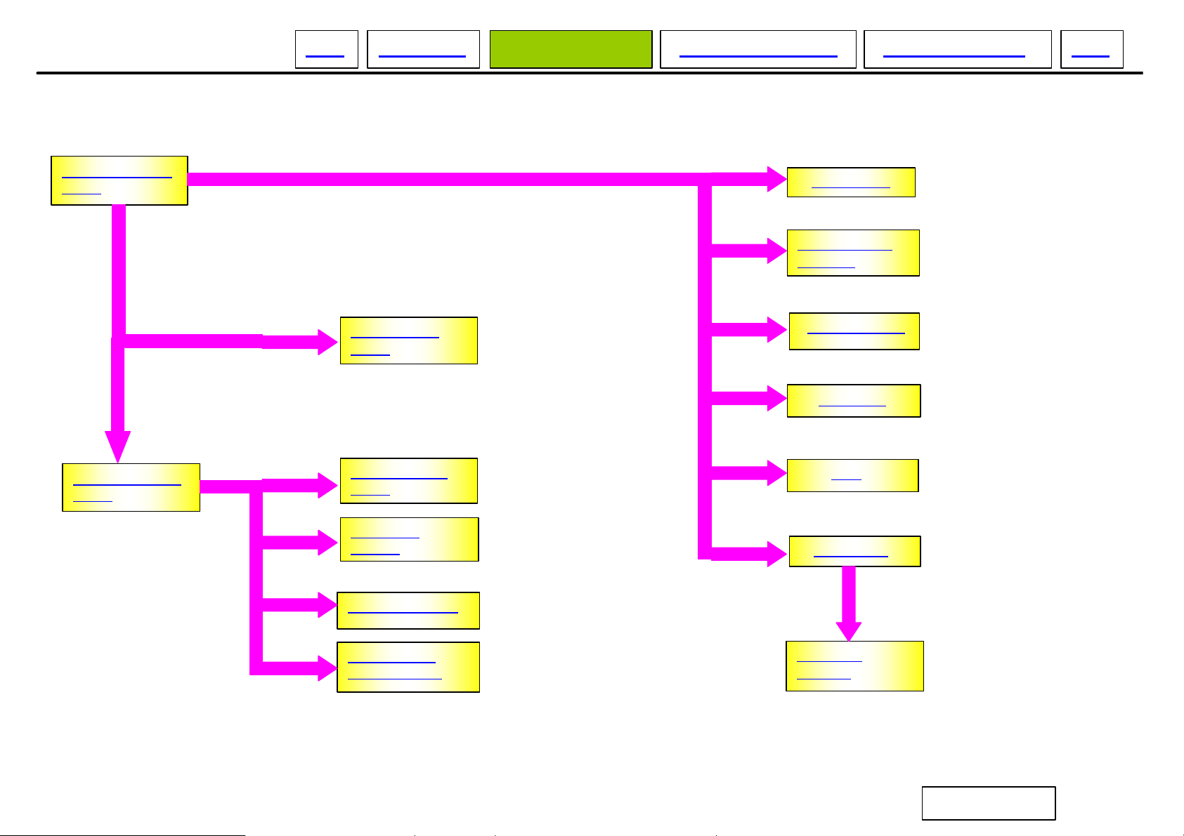
DISASSEMBLY FLOW CHART
LEFT CHASSIS
ASSY
FRONT PANEL
ASSY
TOP COVER
ASSY
BASE COVER
ASSY
OPTICAL
DRIVE
HDD ASSY
SWITCHING
POWER
SYSTEM FAN
MEMORY
CPU
PCI CARD
CARD READER
FRONT USB
/1394 PORT
MOTHER
BOARD
3
Sony Confidential VGC-RB Series
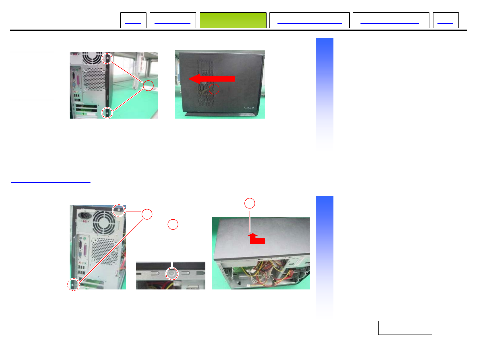
LEFT CHASSIS ASSY
TOP CAUTION DISASSEMBLY FRAME HARNESS EXPLODE VIEW CTO
Procedure to remove
1 Two screws
○
2 Remove the left chassis assy
○
in the direction of arrow
TOP COVER ASSY
1
1
2
2
Procedure to remove
3
1 Two screws
○
2 A screw
○
3 Remove the top cover
○
assy in direction of arrow
4
Sony Confidential VGC-RB Series
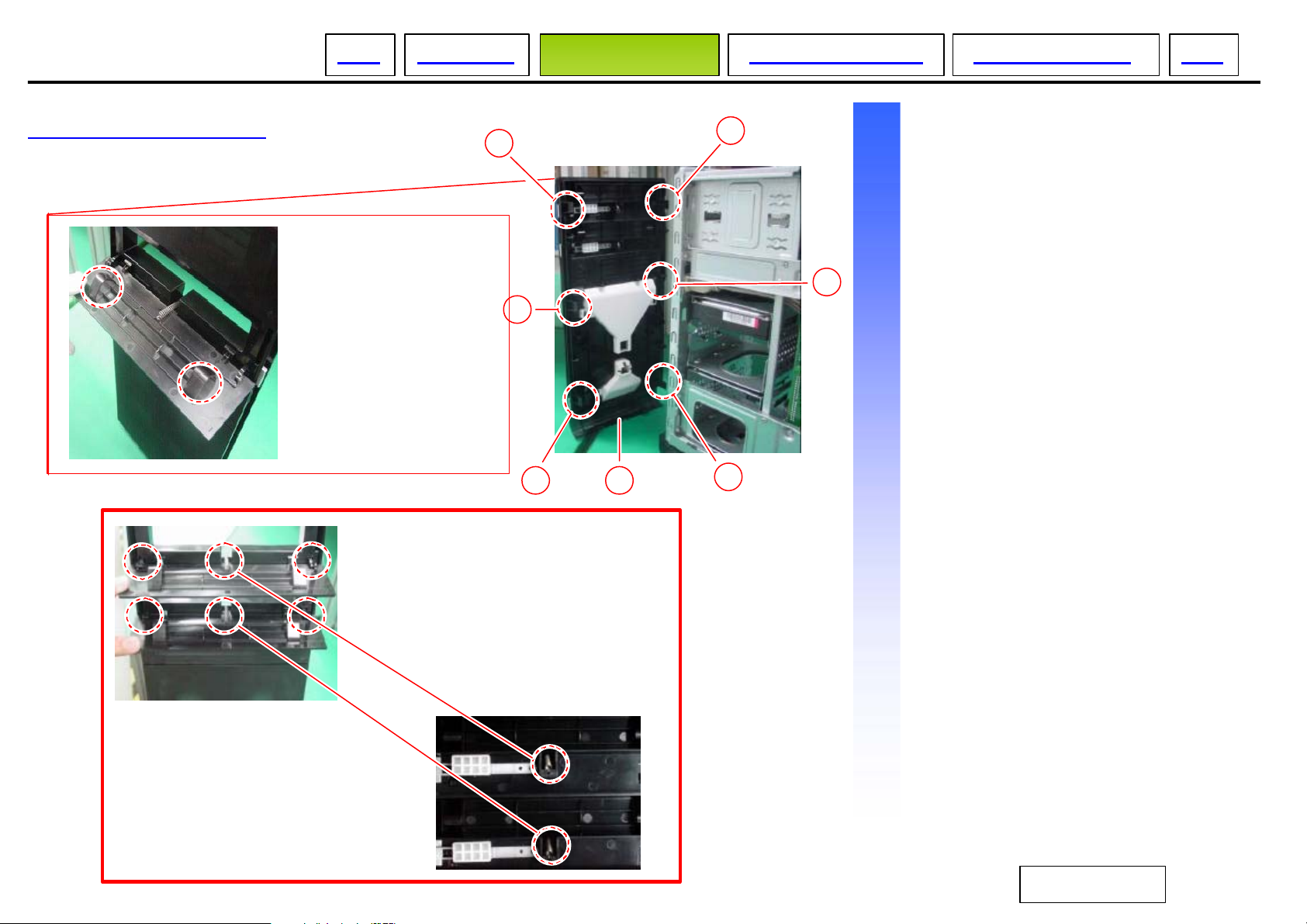
FRONT PANEL ASSY
TOP CAUTION DISASSEMBLY FRAME HARNESS EXPLODE VIEW CTO
Procedure to remove
1 Three claws
○
2 Three claws
○
3 Front panel assy
○
Note: When replacing
an optical door cover,
please apply an oil to the
position shown in the
figure to avoid the optical
drive sticking upon
retraction. Please oil both
sides of the hump.
Oil: LUBRICANT
1
2
2
1
1
3
2
Place to apply: Springs on upper
and lower doors.
Oil: LUBRICANT
Note: Also apply an oil to the 6 position
shown in these photos.
Place to apply: Door hinges and their
compartments.
5
Sony Confidential VGC-RB Series

BASE COVER ASSY
TOP CAUTION DISASSEMBLY FRAME HARNESS EXPLODE VIEW CTO
Procedure to remove
1 A screw
○
OPTICAL DRIVE
1
3
1
4
2
3
2
3
Procedure to remove
2 Pull the claw
○
3 Remove the base in the
○
direction of arrow
1 harness (IDE CD- ROM)
○
2 harness (power)
○
3 Four screws
○
4 Remove the optical drive in
○
the direction of arrow
3
3
4
1
2
6
Sony Confidential VGC-RB Series
CARD READER
2
FRONT USB /1394 PORT
4
TOP CAUTION DISASSEMBLY FRAME HARNESS EXPLODE VIEW CTO
Procedure to remove
1 harness (CARD READER)
○
2
5
1
3
Procedure to remove
2 Two screws
○
3 Remove the CARD READER in
○
the direction of arrow
1 A screw
○
2 Two screws
○
3 Two screws
○
4 USB Cover
○
3
2
6
3
2
1
7
5 1394 Port
○
6 Front USB Port
○
Sony Confidential VGC-RB Series

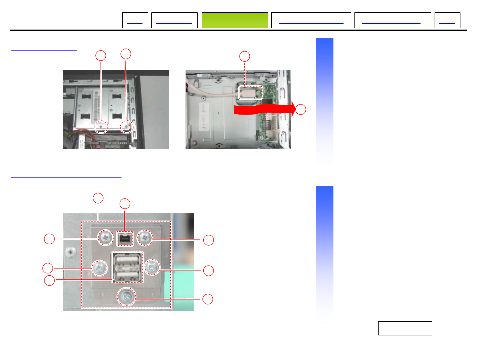
HDD ASSY
TOP CAUTION DISASSEMBLY FRAME HARNESS EXPLODE VIEW CTO
Procedure to remove Procedure to remove
1
2
3
1
55
6
1 Two screws
○
2 harness (power: P5)
○
3 harness (SATA)
○
4 Pull the HDD holder in the
○
direction of arrow.
5 Four screws
○
6 HDD
○
PCI CARD
5
4
2
1
5
1 A screw
○
2 Remove the PCI card in the
○
direction of arrow
8
Sony Confidential VGC-RB Series
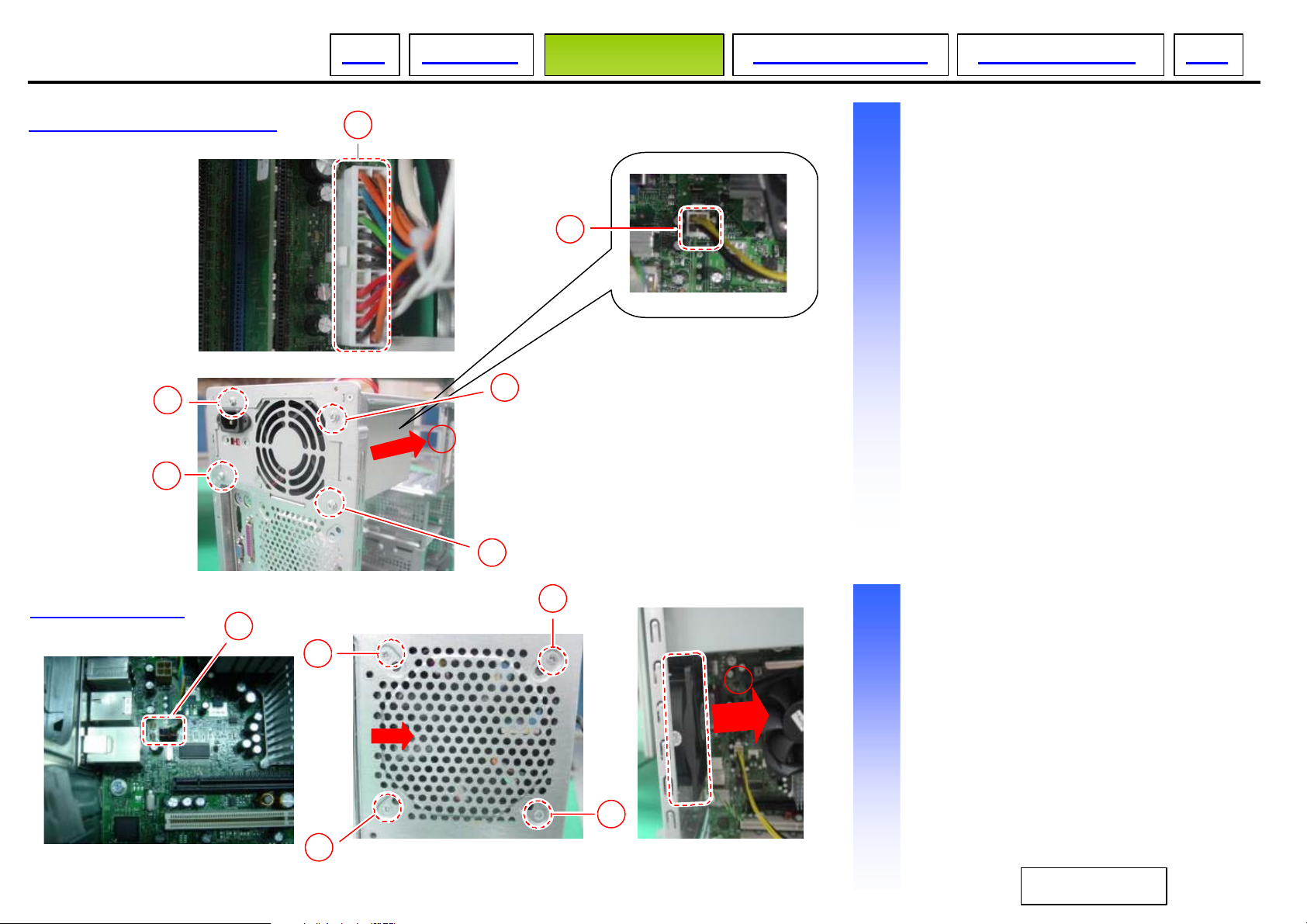
SWITCHING POWER
TOP CAUTION DISASSEMBLY FRAME HARNESS EXPLODE VIEW CTO
Procedure to remove
1
2
1 harness (power: P1)
○
2 harness (power: P3)
○
3 Four screws
○
4 Pull out the switching power in
○
the direction of arrow.
3
3
SYSTEM FAN
3
4
3
Procedure to remove
2
1 harness (System Fan)
1
2
3
2
○
2 Four Screws
○
3 Remove System fan in the
○
direction of arrow
2
9
Sony Confidential
VGC-RB Series
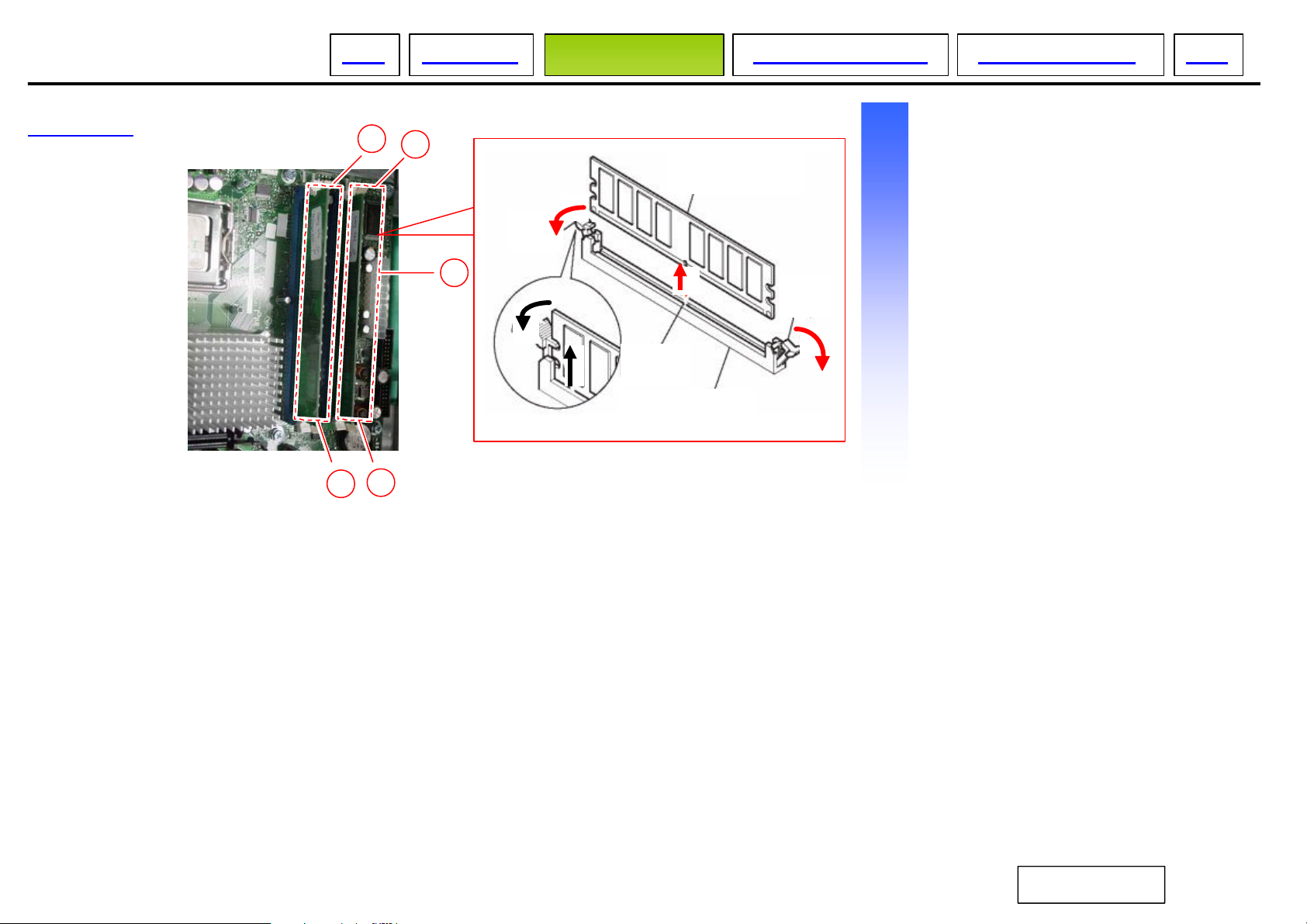
MEMORY
TOP CAUTION DISASSEMBLY FRAME HARNESS EXPLODE VIEW CTO
Procedure to remove
1
1
memory
clip
1 Push down on the t wo clips at
○
the same time to unlatch the
memory
2 Remove the memory by
○
grasping both ends and
2
pulling straight up.
clip
boss
DDR socket
1
1
10
Sony Confidential
VGC-RB Series
 Loading...