

Sony VCR DVW-250P, VCR DVW-250 User Manual

DIGITAL VIDEOCASSETTE RECORDER
DVW-250/250P
TM
OPERATION MANUAL
1st Edition (Revised 3)
Serial No. 10001 and Higher
[English]

WARNING
For the customers in the USA and Canada
To prevent fire or shock hazard, do not
expose the unit to rain or moisture.
To avoid electrical shock, do not open the
cabinet. Refer servicing to qualified
personnel only.
For the customers in the USA
This equipment has been tested and found to comply
with the limits for a Class A digital device, pursuant to
Part 15 of the FCC Rules. These limits are designed to
provide reasonable protection against harmful
interference when the equipment is operated in a
commercial environment. This equipment generates,
uses, and can radiate radio frequency energy and, if
not installed and used in accordance with the
instruction manual, may cause harmful interference to
radio communications. Operation of this equipment in
a residential area is likely to cause harmful interference
in which case the user will be required to correct the
interference at his own expense.
You are cautioned that any changes or modifications
not expressly approved in this manual could void your
authority to operate this equipment.
RECYCLING NICKEL-CADMIUM
BATTERIES
NICKEL-CADMIUM BATTERY.
MUST BE DISPOSED OF PROPERLY.
Nickel-Cadmium batteries are recyclable.
You can help preserve our environment
by returning your unwanted batteries to
your nearest Sony Service Center or
Factory Service Center for collection,
recycling or proper disposal.
Note: In some areas the disposal of
nickel-cadmium batteries in household or
business trash may be prohibited.
For the Sony Service Center nearest you call 1-800222-SONY (United States only)
For the Factory Service Center nearest you call 416499-SONY (Canada only)
The shielded interface cable recommended in this
manual must be used with this equipment in order to
comply with the limits for a digital device pursuant to
Subpart B of Part 15 of FCC Rules.
For the customers in Europe
This product with the CE marking complies with the
EMC Directive (89/336/EEC) issued by the
Commission of the European Community.
Compliance with this directive implies conformity to the
following European standards:
• EN55103-1: Electromagnetic Interference (Emission)
• EN55103-2: Electromagnetic Susceptibility (Immunity)
This product is intended for use in the following
Electromagnetic Environment(s):
E1 (residential), E2 (commercial and light industrial),
E3 (urban outdoors) and E4 (controlled EMC
environment, ex. TV studio).

Table of Contents
Chapter 1 Overview
1-1 Features ........................................................... 1-1
1-1-1 Features of the DVW-250/250P............. 1-1
1-1-2 Digital Betacam Format ......................... 1-1
1-2 System Configuration .................................... 1-2
1-3 Getting the Best Performance from the Unit
.......................................................................... 1-3
Chapter 2 Location and Function of
Parts
2-1 Front Panel ..................................................... 2-1
2-1-1 Operating Controls ................................ 2-2
2-1-2 Status Indications................................... 2-4
2-1-3 Adjustment Controls.............................. 2-6
2-1-4 Time Code Setting Controls .................. 2-8
2-2 Connector Panel ........................................... 2-10
2-2-1 Audio Connectors and Controls .......... 2-11
2-2-2 Video Connectors and Controls........... 2-13
2-2-3 Power Supply and Miscellaneous........ 2-15
Chapter 3 Getting Started
3-1 Power Supply .................................................. 3-1
3-1-1 Using a Battery Pack ............................. 3-1
3-1-2 Using an AC Power Supply................... 3-3
3-1-3 Powering On and Off............................. 3-4
3-1-4 Checking the Remaining Battery
Capacity ................................................. 3-4
3-2 Cassettes .......................................................... 3-5
3-2-1 Cassette Types ....................................... 3-5
3-2-2 Preventing Accidental Erasure of
Recordings ............................................. 3-5
3-2-3 Loading and Unloading Cassettes ......... 3-5
3-2-4 Checking the Remaining Tape............... 3-7
3-3 Adjusting the Display and Indicator
Brightness........................................................ 3-8
4-1-5 Selecting the Monitoring Mode for
Recording ............................................... 4-7
4-1-6 Setting Time Values .............................. 4-7
4-1-7 Locking the Time Code Generator to an
External Signal..................................... 4-11
4-2 Procedures for Recording............................ 4-13
4-2-1 Preventing Inadvertent Operations During
Recording ............................................. 4-13
4-2-2 Recording Video and Audio ................ 4-13
4-2-3 Audio Dubbing on the Cue Track........ 4-15
Chapter 5 Playback
5-1 Preparations for Playback............................. 5-1
5-1-1 Selecting the Sound to Be Monitored.... 5-1
5-1-2 Monitoring with a Television Without
Video Input Connections ....................... 5-1
5-1-3 Using a Field Pickup Unit for Signal
Transmission .......................................... 5-2
5-1-4 Playback Synchronized to an Exernal
Signal ..................................................... 5-2
5-2 Procedures for Playback................................ 5-3
5-2-1 Normal Speed Playback......................... 5-3
5-2-2 High Speed Searching ........................... 5-3
5-3 Reading and Displaying Time Code and User
Bits ................................................................... 5-5
Chapter 6 Setup Operations
6-1 Setup Menu Organization ............................. 6-1
6-2 Basic Setup Procedure ................................... 6-2
6-3 Setup Menu Settings ...................................... 6-3
Chapter 7 Editing System
Configuration
7-1 When Not Using an Editor ............................ 7-1
7-2 Using an Editor............................................... 7-2
Chapter 4 Recording
4-1 Preparations for Recording........................... 4-1
4-1-1 Connecting Digital Equipment .............. 4-1
4-1-2 Connecting Analog Equipment ............. 4-2
4-1-3 Making Video Input Settings................. 4-3
4-1-4 Making Audio Input Settings ................ 4-5
Appendixes
Warning Indications............................................. A-1
Using the Carrying Case ...................................... A-2
Specifications......................................................... A-3
Index ........................................................................I-1
Table of Contents 1


1-1 Features
Chapter 1 Overview
The DVW-250/250P is a portable videocassette
recorder in the Digital Betacam series. It allows
recording and playback of sound and picture in the
Digital Betacam format.
1-1-1 Features of the DVW-250/
250P
The following are some of the features of the DVW250/250P.
Flexible input/output interfaces
The unit is designed to accept either analog video
(component/composite) and audio signals, or D1
format serial digital video/audio signals. It is therefore
highly suitable for use not only in analog systems but
also in all-digital systems.
Analog input signals pass through the built-in A/D
converter, and are converted to 10-bit digital video
signals and 20-bit digital audio signals. Similarly,
both digital and analog output signals are provided, for
flexible support of mixed analog-digital systems.
Simple system configuration using the serial
digital interface
The serial digital inputs to the SDI (Serial Digital
Interface) connector provide for one video signal and
four audio channels through a single BNC connector.
When connected to other digital equipment, this makes
setting up and transporting, for example on outside
assignments, extremely straightforward.
High quality digital recording
This unit records both sound and vision on the tape in
the Digital Betacam format (see the figure at the end of
this page). Since all internal processing is digital,
signal outputs are stable, and reproduction is very
accurate.
Designed for field operations
The unit is compact and lightweight (main unit
approximately 6.6 kg or 14 lb 8 oz), making it ideal for
carrying and operating in the field. The power
consumption while recording is about 26 W (with the
MODE switch in the SAVE position and the CONFI
switch in the OFF position), and the optional battery
pack provides about two hours of continuous
recording.
color playback signal is available at 24 times normal
speed, making tape cuing both fast and accurate.
Two LCD units for ease of operation
The front panel includes two LCDs: the smaller shows
the unit status and time indications, and the larger
displays the audio level meters, the video level meters,
or the setup menu.
By switching the display mode, it is possible to change
the audio level indications for fine adjustment in a
narrower range.
Backlighting is provided to make the displays easier to
read in gloomy conditions.
1-1-2 Digital Betacam Format
Overview
The Digital Betacam format is based on the
conventional Betacam and Betacam SP formats, and
allows high-performance digital recording and
playback.
One of the features of the Digital Betacam format is
the introduction of a new technique known as
“coefficient recording,” which allows the data rate of
the video signal to be reduced to approximately half.
This makes 120 minutes or more of recording possible
with an “L” size cassette.
The compressed video signal includes error-correcting
codes (ECC), which correct the signal on playback.
This powerful error-correcting system provides the
improved signal reliability which is another feature of
the Digital Betacam format.
Recording format
The processing of the Digital Betacam video signal
conforms to the D1 4:2:2 component digital format,
with digitization according to ITU-R BT. 601.
The following figure shows schematically the Digital
Betacam recording format on the tape. A set of six
diagonal tracks contains one field of video and four
channels of audio information.
Tape transport direction
Direction of head
movement
Cue track
Video sectors
Audio sectors (1–4)
Video sectors
Chapter 1 Overview
High speed search with color picture
The search speed can be set to 2 times, 5 times or 8
times normal speed. Using rewind or fast forward, a
Time code track
Control track
Tape recording format for Digital Betacam
Chapter 1 Overview 1-1
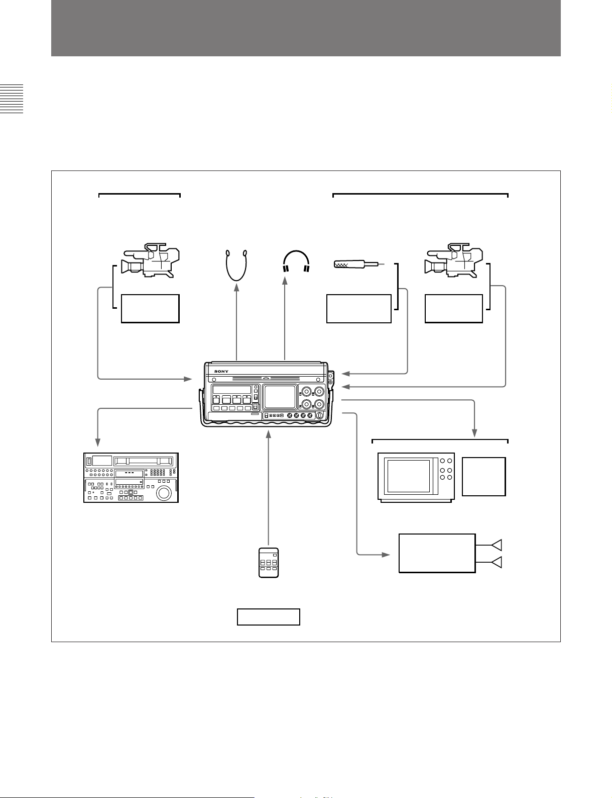
1-2 System Configuration
The following figure shows the configuration of a
typical system centered on the DVW-250/250P.
Chapter 1 Overview
For details, such as the connector names, see Section 4-1-1
“Connecting Digital Equipment” (page 4-1) and Section 41-2 “Connecting Analog Equipment” (page 4-2).
Switching
Digital equipment
Color video camera
VTR etc.
Single video/audio input
channel
Single video/audio
output channel
VTR etc.
Earphone Headphones
DVW-250/250P
Microphone
Tape recorder,
etc.
Four audio input
channels (1 to 4)
Four audio output
channels
Analog equipment
Color video camera
VTR etc.
Composite signal
Single video/audio
input channel
Two video output
channels (composite)
Component signal
Switching
1-2 Chapter 1 Overview
Control signal
channel
BVR-3 Remote Controller
or
Editor etc.
Typical DVW-250/250P system configuration
Video monitor
Stereo amplifier Speakers
VTR, FPU (Field
Pickup Unit), etc.

1-3 Getting the Best Performance from the Unit
Notes on operation and storage
Protect the unit from violent shocks
It is possible to damage the internal circuitry and
mechanism or spoil the external finish.
After use
Turn the power switch off.
When not using the unit for a long period
Remove the cassette and batteries.
Operating and storage locations
Store the unit in a level place which is well ventilated.
Avoid operation or storage in the following locations:
•In extremely hot or extremely cold conditions
•In extremely dusty conditions
•In very high humidity
•Where the unit will be subjected to severe vibration
•Close to strong magnetic fields
•Exposed to direct sunlight for long periods, or close
to heating equipment
Cleaning the video heads
Use the Sony BCT-5CLN or BCT-D12CL Cleaning
Cassette for cleaning the audio and video heads.
Follow the instructions with the cleaning cassette.
Related manuals
In addition to this Operation Manual, the following
manuals are available.
These should be consulted as necessary.
•Maintenance Manual Part 1 (supplied)
Describes the maintenance of this unit.
•Maintenance Manual Part 2 (option)
Contains circuit diagrams and adjustment procedures
required for the maintenance of this unit.
Chapter 1 Overview
Condensation
If you move the unit suddenly from a cold place to a
warm place, or use it in a very humid location,
condensation may form on the head drum. If the unit
is operated in this state, the tape may adhere to the
drum, and cause a failure or even permanent damage.
Take the following steps to prevent this from
happening:
•Remove the cassette before operating the unit in
conditions where condensation is likely to form.
•If the HUMID indication is showing, condensation is
present: wait until the HUMID indication disappears,
and then insert a cassette.
•Do not load a cassette on which condensation has
formed into the unit.
Chapter 1 Overview 1-3

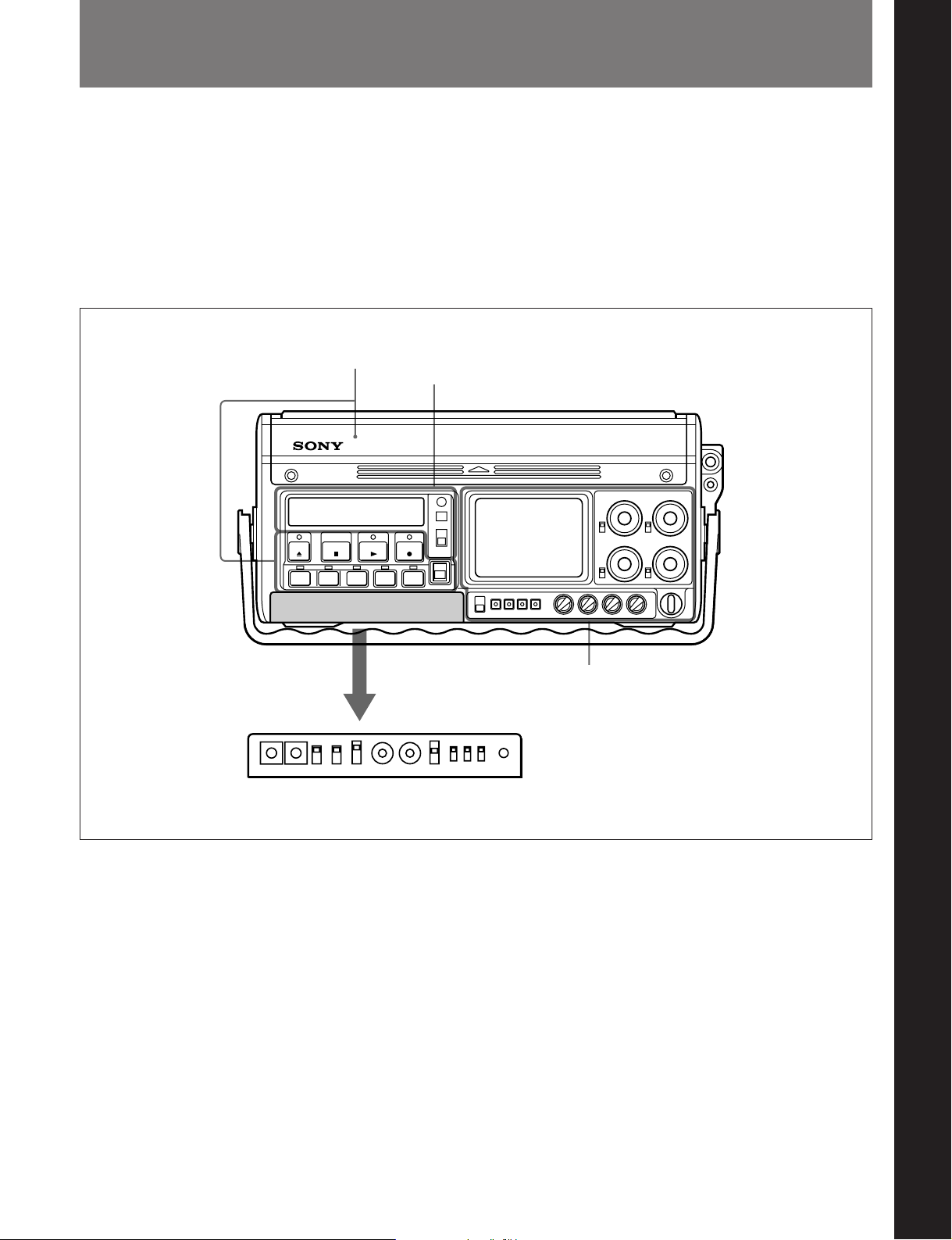
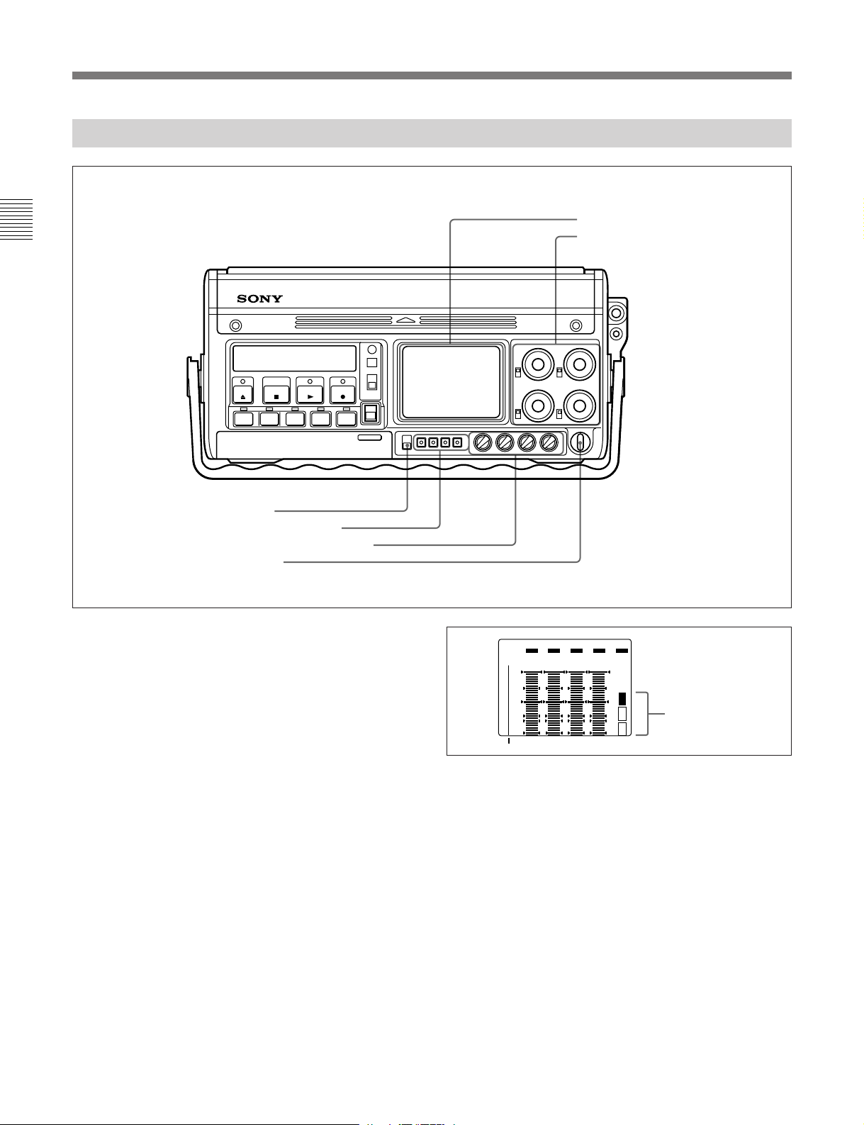
2-1 Front Panel
The front panel is divided into four sections as follows:
• Operating controls
• Status indications
• Adjustment controls
• Time code setting controls
Of these, the controls for time code settings are
normally covered by a hinged lid.
Operating controls
Status indications
Chapter 2 Location and Function of Parts
Chapter 2 Location and Function of Parts
Open the lid.
Time code setting controls
Adjustment controls
Front panel
Chapter 2 Location and Function of Parts 2-1
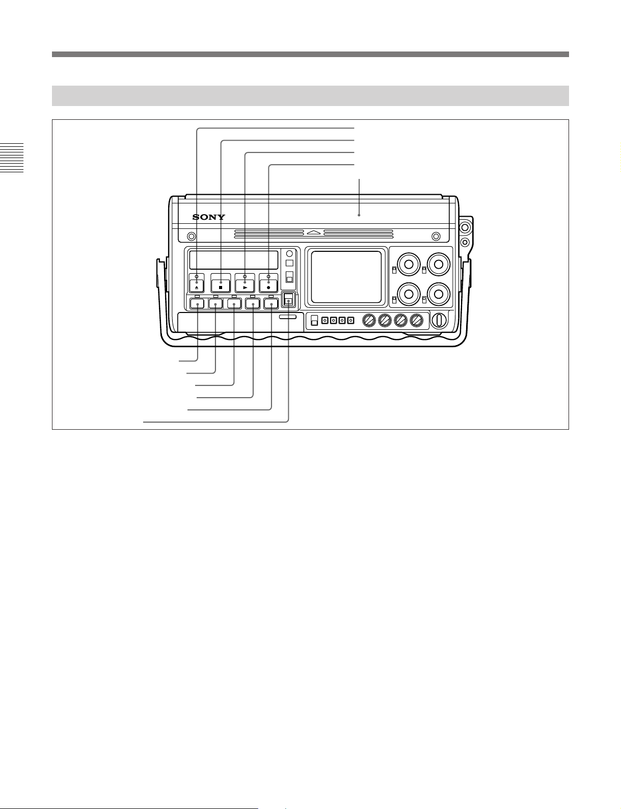
2-1 Front Panel
2-1-1 Operating Controls
Chapter 2 Location and Function of Parts
1 EJECT button and indicator
2 STOP button
3 PLAY button and indicator
4 REC button and indicator
5 Cassette compartment
6 REW button and indicator
7 F FWD button and indicator
8 SEARCH button and indicator
9 CUE DUB button and indicator
0 PAUSE button and indicator
!¡ KEY INHI switch
Operating controls
1 EJECT 6 button and indicator
Press this button to eject the cassette. The indicator
lights while the cassette is being ejected.
2 STOPp button
Press this button to stop the tape transport.
(
3 PLAY
button and indicator
Press this button to play back the tape. To start
recording, press this button and the REC button
simultaneously. For audio dubbing, press this button
and the CUE DUB button simultaneously.
The indicator lights during playback, recording, or
audio dubbing.
4 RECr (record) button and indicator
To start recording, press this button and the PLAY
button simultaneously. The indicator flashes during
recording.
By pressing this button alone while the tape transport
is stopped, or during fast forward, rewind or playback,
1)
it is possible to monitor an E-E signal
.
Pressing this button alone while no cassette is loaded
2)
switches the unit to E-E mode
.
Consecutive recording
When making consecutive recordings, using the
PAUSE button to stop recording ensures that
successive takes are joined without picture breakup.
If you press the STOP button to stop recording, then
restart by holding down the REC button then pressing
the PLAY button, the later recording will overlap the
previous one by a few frames, but there will again be
no picture breakup. On the other hand, if you hold
..........................................................................................................................................................................................................
1) E-E signal
Abbreviation of “Electric-to-Electric signal,” meaning
that the signal passes through internal electric circuits,
but not through magnetic conversion circuits such as
heads and tapes.
2) E-E mode
Abbreviation of “Electric-to-Electric mode,” meaning
the state of the unit in which it is possible to monitor an
E-E signal. This mode is used for confirming input
signals before recording.
2-2 Chapter 2 Location and Function of Parts

down the PLAY button then press the REC button,
recording starts immediately, but there may be picture
breakup.
However, once a cassette has been removed and
reinserted, even pressing the REC button then the
PLAY button may sometimes not result in a proper
join.
5 Cassette compartment
Raise the lid in the direction indicated (¢) and insert
the cassette.
6 REW0 (rewind) button and indicator
Press this button to rewind the tape. Pressing this
button after pressing the SEARCH button starts a
search of the tape in the reverse direction at a
maximum 8 times normal speed (selectable from 2
times, 5 times and 8 times). The indicator lights
during the rewind operation, and goes off when it is
completed.
7 F FWD) (fast forward) button and indicator
Press this button to fast forward the tape. Pressing this
button after pressing the SEARCH button starts a
search of the tape in the forward direction at a
maximum 8 times normal speed (selectable from 2
times, 5 times and 8 times). The indicator lights
during the fast forward operation, and goes off when it
is completed.
9 CUE DUB button and indicator
Hold this button down, then press the PLAY button to
record analog sound on the cue track of the tape (see
page 1-1). This records the channel 4 audio.
Pressing this button alone allows the channel 4 audio
to be monitored in E-E mode.
The indicator flashes during recording, and lights
continuously during monitoring.
0 PAUSEP button and indicator
Press this button to pause the tape movement during
recording or playback. While paused, the indicator
flashes. Pressing the button again turns the indicator
off, and ends the paused state.
!¡ KEY INHI (inhibit) switch
When this switch is in the ON position, all operation
buttons are disabled, thus preventing a possible
inadvertent operation.
To release this lock, return the switch to the OFF
position.
Note
When the KEY INHI switch is in the OFF position,
only the STOP button and PAUSE button operate
during recording, but at all other times, all buttons
operate.
Chapter 2 Location and Function of Parts
8 SEARCH button and indicator
Press this button to play back at high speed. After
pressing this button, press the F FWD button to play
back in the forward direction or the REW button to
play back in the reverse direction. The speed can be 2
times, 5 times or 8 times normal speed, and this is
selectable by a setup operation.
The indicator lights during the search operation.
Pressing the button again turns the indicator off, and
ends the search function.
Chapter 2 Location and Function of Parts 2-3
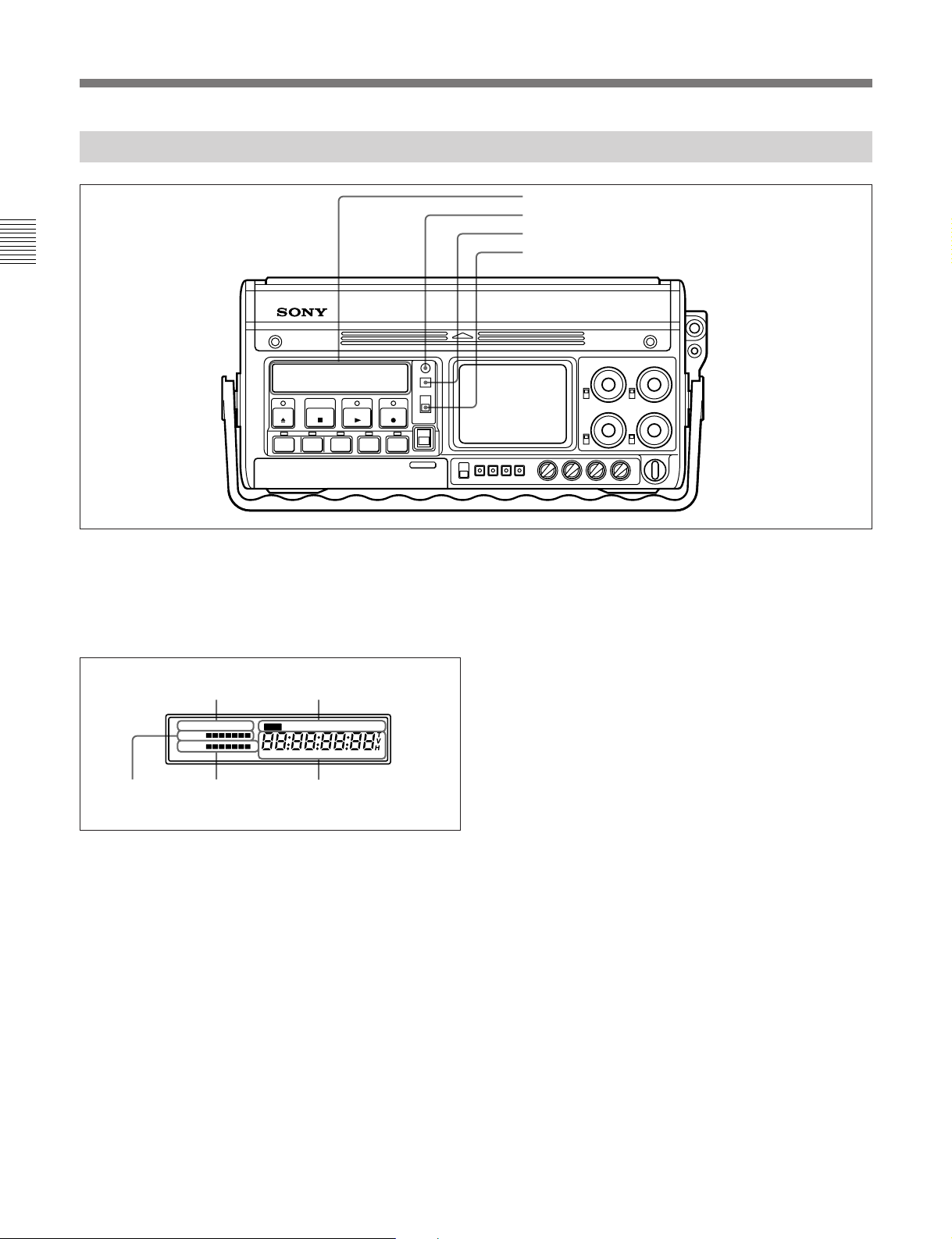
2-1 Front Panel
2-1-2 Status Indications
Chapter 2 Location and Function of Parts
1 Status indication panel
2 WARNING indicator
3 RESET button
4 DISPLAY switch
Status indications
1 Status indication panel
This displays warnings, the tape remaining, the battery
capacity remaining, the operating status, and time
indications.
remaining
Warning
indications
RF SERVO HUMID SLACK PB VITC NDF EXT-LK 2FLD
TAPE
BATT E F
Battery capacity
remaining
Status indication panel
Operating status
indications
H MIN SEC FRM
Time indicationsTape
The details of these indications are as follows:
Warning indications
The following indications appear in the event of a fault
in the unit:
RF: Recording or playback is not possible because
the video heads are clogged, or there is a fault in
the circuit.
SERVO: The drum servo or capstan servo lock is
lost.
HUMID: There is condensation on the head drum.
Alternatively, the humidity is high.
SLACK: The tape winding is not correct.
For more details, see the section “Warning Indications”
(page A-1).
Operating status indications
These show the operating status of the unit, as follows:
DIAG: in diagnosis mode
PB: when the playback time code is displayed.
VITC: when the time code displayed is the VITC
(Vertical Interval Time Code)
NDF: in non-drop frame mode (DVW-250 only) (see
the footnotes on page 4-9)
EXT-LK: when the time code on this unit is locked
to the time code on an external unit
2FLD: when the internal time code generator is not
color frame locked
1)
..........................................................................................................................................................................................................
1) Color frame lock
This forces the time code frame number to be even for
the first and second color fields and odd for the third and
fourth color fields. When there is color frame
information in the input video signal and the time code is
not locked to an external time code, then in the F-RUN
mode the color frame lock is automatically applied.
2-4 Chapter 2 Location and Function of Parts

Time indications
This display shows the value selected by the
DISPLAY switch from CTL (control track running
time), time code, or user bits. However, if the REAL
TIME record/set switch (see page 2-9) in the time code
setting controls is in the SET position, the real time
appears here, regardless of the DISPLAY switch
setting.
Tape remaining indication
This shows the length of the remaining tape. Each
segment corresponds to 5 minutes of remaining tape,
but if 30 minutes of tape or more remains, all seven
segments show.
For details of the segment indications and remaining tape
times, see Section 3-2-4 “Checking the Remaining Tape
(page 3-7).
When the remaining tape time is approximately two
minutes, the leftmost segment and the “TAPE”
indication flash, and simultaneously the WARNING
indicator flashes, accompanied by an intermittent
warning tone. At the end of the tape, the WARNING
indicator stays on, and the warning tone becomes
continuous.
Battery capacity remaining indication
This shows the remaining battery capacity. When the
battery pack is fully charged, all seven segments show.
As the battery capacity decreases, the segments
disappear in turn from the right.
For details of the segment indications and remaining battery
capacity, see Section 3-1-4 “Checking the Remaining
Battery Capacity (page 3-4).
3 RESET button
This resets the time display.
When the CTL value (control track running time) is
displayed, it is reset to “0:00:00:00”. When one of the
time code, or user bit value or real time is displayed, it
is reset to “00:00:00:00”.
4 DISPLAY switch
This selects the time value displayed.
CTL: Displays the tape running time in hours,
minutes, seconds and frames.
TC: Displays a time code.
U-BIT: Displays the user bits.
Note that when the user bits are displayed, no
colons appear.
However, the value displayed is not totally determined
by the setting of the DISPLAY switch. The REAL
TIME record/set switch (see page 2-9) takes
precedence, followed by the F-RUN/R-RUN switch
(see page 2-9), and finally the DISPLAY switch
setting.
Switch settings and time value displayed
REAL TIME
record/set
switch
position
SET Ignored Ignored Real time
REC ON or
OFF
F-RUN/
R-RUN
switch
position
SET TC or CTL Time code
F-RUN or RRUN
DISPLAY
switch
position
U-BIT User bits
CTL CTL
TC Time code
U-BIT User bits
Value
displayed
Chapter 2 Location and Function of Parts
When the battery pack is almost exhausted, the
leftmost segment and the “BATT” and “E” indications
flash, and simultaneously the WARNING indicator
flashes, accompanied by an intermittent warning tone.
When the battery pack is completely exhausted, the
WARNING indicator stays on, and the warning tone
becomes continuous.
2 WARNING indicator
This lights or flashes when the battery pack is nearly
exhausted, there is less than two minutes of tape left,
or there is a fault in the unit.
For more details, see the section “Warning Indications”
(page A-1).
Chapter 2 Location and Function of Parts 2-5
2-1 Front Panel
2-1-3 Adjustment Controls
Chapter 2 Location and Function of Parts
1 Signal level and menu display
2 Recording level control knobs and
UNI/VAR switches
3 LIGHT switch
4 Display operating buttons
5 AUDIO PB LEVEL control knobs
6 POWER switch
Adjustment controls
1 Signal level and menu display
Pressing the DISPLAY button in the display operating
buttons cycles this display through the audio level
meters, video level meters, and setup menus.
When the unit is powered on, and whenever five
minutes elapse without an operation, the display
reverts to the audio level meters.
When the display is showing the audio level meters,
the indication “CH CONDI” (channel condition)
appears. One of the three segments above it appears,
to indicate the status of the playback signal.
Top segment: The playback signal is normal.
Middle segment: The playback signal is somewhat
degraded, but adequate.
Bottom segment: The playback signal is degraded.
If this segment appears continuously, head
cleaning or an internal servicing is required.
OVER OVER OVEROVER EMPH
FINE
dB
0
+2
-10
+1
0
-20
-1-2
-30
-40
-60
FULL FINE CH-1 CH-2 CH-3 CH-4 CH
CONDI
display of the channel
condition
2 Recording level control knobs and UNI/VAR
(unity/variable) switches
When the audio inputs are analog, these knobs can be
used to adjust the recording level on each of the four
channels, while watching the audio level meters.
Below and to the left of each knob is a UNI/VAR
(unity/variable) switch, and the position of this switch
affects the recording level as follows:
UNI: The input signal is recorded without changing
its level, regardless of the position of the control
knob.
VAR: The position of the control knob determines
the recording level.
2-6 Chapter 2 Location and Function of Parts

3 LIGHT switch
This switches on and off the illumination of the status
indication panel (see page 2-4) and signal level and
menu display, and also controls the brightness of the
indicators for the operating buttons.
ON: Turns the display illumination on.
OFF: Turns the display illumination off.
BRT: Turns the display illumination off, and
increases the brightness of the indicators. This
makes the indicators easier to see outdoors, for
example.
4 Display operating buttons
There are four buttons, and their functions depend on
the current state of the signal level and menu display,
as shown in the following table.
Functions of display operating buttons
Display
state
Operating
button
DISPLAY Switch to
UP —
FREEZE/DOWN Freeze
FINE/SET Toggle
Audio level
meters
video level
meters
(No
function)
playback
frame or
end freeze
display
mode
(FULL/
FINE)
Video
level
meters
Switch to
setup
menu
—
(No
function)
—
(No
function)
—
(No
function)
Setup menu
Switch to
audio level
meters
Move cursor
(*) up
Move cursor
(*) down
Select item
indicated by
cursor (*)
5 AUDIO PB (playback) LEVEL control knobs
These adjust the playback levels for each separate
channel of analog audio output.
6 POWER switch
This powers the unit on and off.
This switch also controls the power supply to a
camera connected to the CAMERA connector on the
connector panel (see page 2-13), a remote controller
connected to the DC OUT connector (see page 2-15),
and an RF modulator connected to the RFU OUT
connectors (see page 2-15).
Note that the time code circuits continue to operate
when the unit is powered off.
Chapter 2 Location and Function of Parts
Chapter 2 Location and Function of Parts 2-7
2-1 Front Panel
2-1-4 Time Code Setting Controls
Chapter 2 Location and Function of Parts
Pull the projecting
lug forward.
1 VITC switches
2 VITC REC switch
3 DISPLAY switch
4 F-RUN/R-RUN switch
5 ADVANCE button
6 SHIFT button
REC DISPLAY
ON LTC
A VITC
7 REAL TIME record/set switch
8 REAL TIME insertion time code selection switch
9 EXT-LOCK/U-BIT switch
0 DF/NDF switch (DVW-250 only)
!¡ DIAG switch
B OFF VITC
F-RUN ADVANCE SHIFT REAL TIME
R-RUN
Time code setting controls
1 VITC switches
These determine the lines in the vertical blanking
1)
interval in which the VITC
is recorded.
For the DVW-250, the factory default is for switch A
to be in position 6 (line 16) and switch B in position 8
(line 18).
For the DVW-250P, the factory default is for switch A
to be in position C (line 19) and switch B in position E
(line 21).
EXT-LOCK/U-BIT
DFONLTC U-BIT
SET
SET
REC
ON
OFF
SET
VITC U-BITOFF NDF
2 VITC REC (record) switch
This selects whether or not to record the VITC.
ON: Record the VITC.
OFF: Do not record the VITC.
DIAG
For details of the relation between the switch positions and
the line numbers, see page 4-10.
..........................................................................................................................................................................................................
1) VITC (Vertical Interval Time Code)
This time code signal is inserted in two lines of the
vertical blanking interval. This allows the time code to
be read even at very slow playback speeds.
2-8 Chapter 2 Location and Function of Parts

3 DISPLAY switch
This selects which time code is displayed in the status
indication panel (see page 2-4). This switch is only
effective when the DISPLAY switch by the status
indication panel (see page 2-5) is set to the TC or UBIT position.
LTC: Display the LTC (Longitudinal Time Code).
VITC: Display the VITC.
4 F-RUN/R-RUN (free-run/record-run) switch
This selects the operating mode of the internal time
code generator.
F-RUN: The time code generator keeps running,
regardless of the operating state of the unit. Use
this position when setting the time code to real
time or synchronizing it to an external time code.
SET: Move the switch to this position when setting
the time code or user bits value.
R-RUN: The time code generator runs only while
recording. This produces a tape with consecutive
time code values, even when shot intermittently.
5 ADVANCE button
When setting the time code or user bits value,
pressing this button increments the digit which is
flashing.
This button is effective only when the F-RUN/RRUN switch or REAL TIME record/set switch is in
the SET position.
9 EXT-LOCK/U-BIT switch
This selects whether or not to lock the user bit data to
external user bit data.
ON: The user bit value is locked to the user bit value
inserted in the external time code.
OFF: The user bit value set on this unit is used.
0 DF/NDF switch (DVW-250 only)
This selects whether to use drop frame mode or nondrop frame mode.
For an explanation of the significance of these modes, see
the footnotes on page 4-9.
DF: drop frame mode
NDF: non-drop frame mode
!¡ DIAG (diagnosis) switch
Press this switch to carry out diagnosis on the unit.
For details, refer to the supplied Maintenance Manual Part
1.
Chapter 2 Location and Function of Parts
6 SHIFT button
When setting the time code or user bits value,
pressing this button cycles through the digits, flashing
the one which can be changed. This button is
effective only when the F-RUN/R-RUN switch or
REAL TIME record/set switch is in the SET position.
7 REAL TIME record/set switch
This selects whether or not to record the real time as
user bit data. It is also used for setting the real time.
REC ON: Record the real time as user bit data.
OFF: Do not record the real time as user bit data.
SET: Set the real time.
8 REAL TIME insertion time code selection
switch
This selects whether to insert the real time as user bit
data in the LTC or VITC.
LTC U-BIT: Insert the user bit value in the LTC.
VITC U-BIT: Insert the user bit value in the VITC.
Chapter 2 Location and Function of Parts 2-9
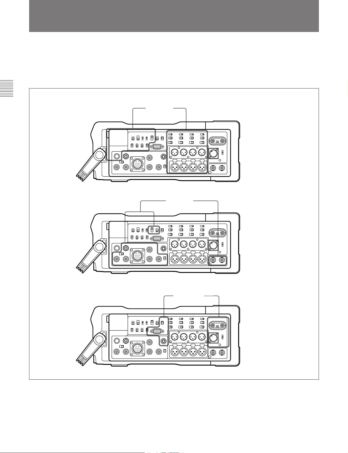
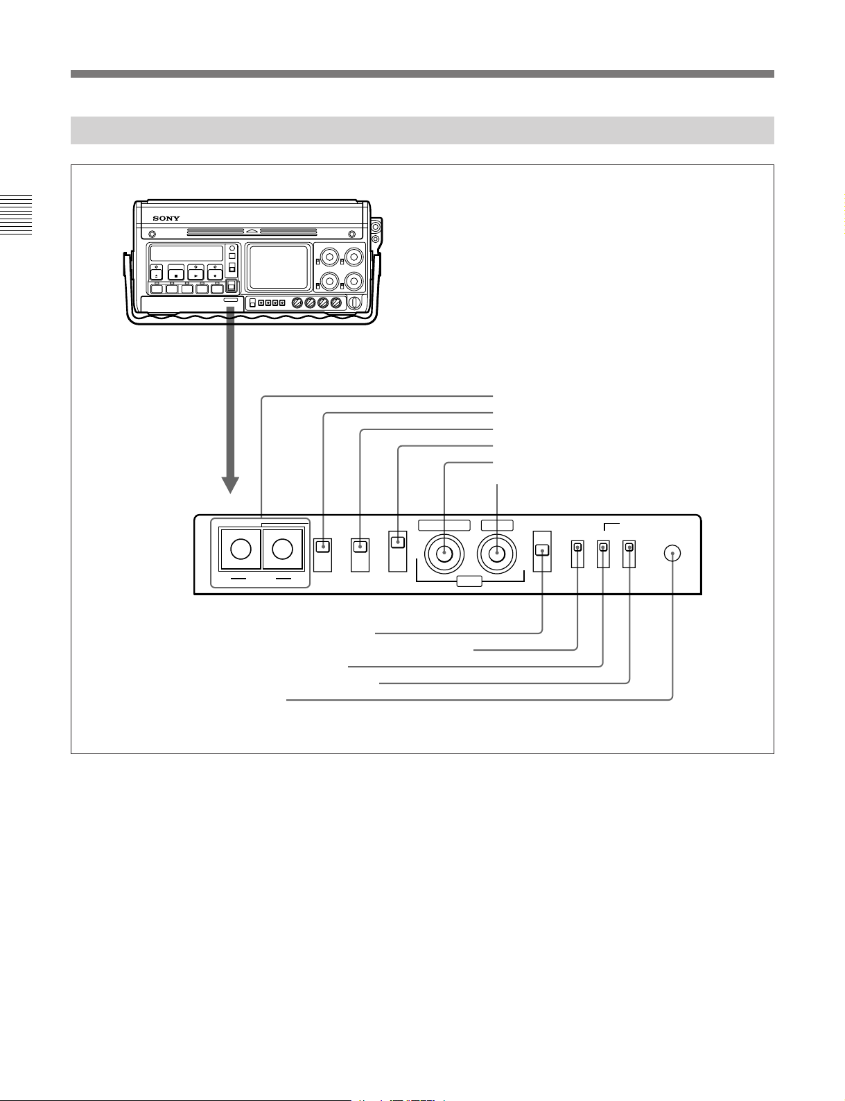
2-2 Connector Panel
This section describes the connector panel under the
following three headings:
• Audio connectors and controls
• Video connectors and controls
• Power supply and miscellaneous
Chapter 2 Location and Function of Parts
Audio connectors
and controls
Video connectors
and controls
2-10 Chapter 2 Location and Function of Parts
Power supply and
miscellaneous
Connector panel
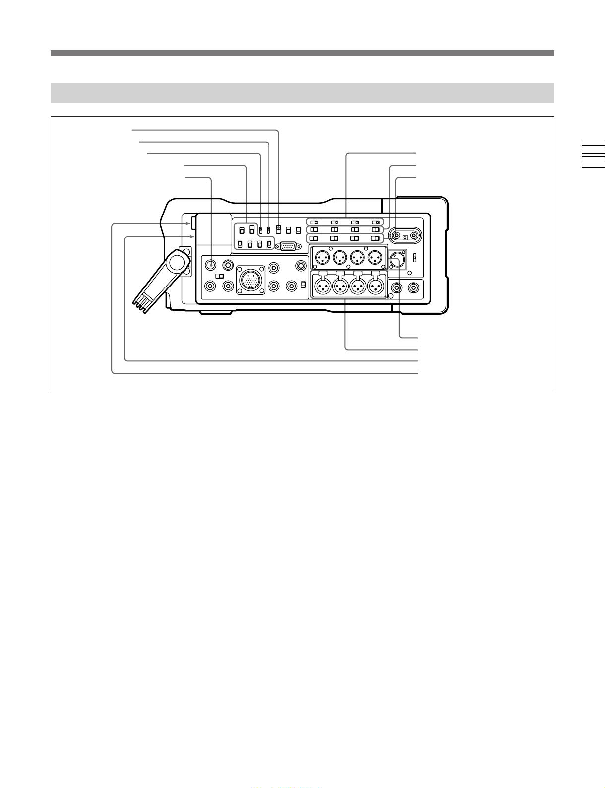
2-2-1 Audio Connectors and Controls
1 CONFI switch
2 CUE REC switch
3 CH-3/4 OUT switch
4 MONITOR SELECT switches
5 PHONE LEVEL control knob
6 +48 V switches (DVW-250P only)
7 CAMERA/LINE switches
8 Audio input level switches
9 AUDIO IN connectors
0 AUDIO OUT connectors
!¡ EARPHONE jack
!™ HEADPHONES jack
Chapter 2 Location and Function of Parts
Audio connectors and controls
1 CONFI (confidence) switch
This selects the mode for monitoring during recording.
Note that this switch applies to both video and audio.
ON: Monitor the simultaneous playback of the
recorded signals from the confidence heads.
ECC (Error Correcting Codes): Monitor the input
signals unchanged (in E-E mode). If a serious
error is detected while recording the signals, a
warning indication is given.
OFF: Monitor the input signals unchanged (in E-E
mode). The RF envelope is monitored during
recording, and if a fault occurs a warning
indication is given.
The ON setting results in the highest power
consumption, and the OFF setting the lowest. When
using the unit with a battery pack, set the CONFI
switch to the ECC or OFF position.
2 CUE REC (record) switch
It is possible to mix the analog audio input signals and
record them on the analog cue track on the tape. This
switch determines whether or not to record on the cue
track during normal recording. When this switch is in
the ON position, channels 1 to 4 of the analog audio
input are mixed and recorded on the cue track.
When using the CUE DUB button on the front panel
(see page 2-3) for cue dubbing, the audio signal is
recorded on the cue track regardless of the position of
this switch.
3 CH-3/4 (channels 3 and 4) OUT switch
This selects the output from channels 3 and 4 of the
AUDIO OUT connectors.
MON: the signals selected by the MONITOR
SELECT switches
LINE: the signals of audio channels 3 and 4
4 MONITOR SELECT switches
These select the audio signals which can be monitored
using the EARPHONE jack, HEADPHONES jack,
and RFU OUT connector. When the CH-3/4 OUT
switch is in the MON position, these switches also
select the audio output from channels 3 and 4 of the
AUDIO OUT connectors.
CUE: the audio from the cue track
DA: Use the channels selected by the switch to the
right.
1/2: audio channels 1 and 2
3/4: audio channels 3 and 4
MIX: A mix of those of the four channels for
which the corresponding switches below are
in the ON position.
Chapter 2 Location and Function of Parts 2-11

2-2 Connector Panel
5 PHONE LEVEL control knob
This adjusts the level of audio output to the
EARPHONE and HEADPHONES jacks.
6 +48 V switches (DVW-250P only)
For each of the four channels, these turn on or off the
Chapter 2 Location and Function of Parts
48 V microphone phantom power supply to the
corresponding AUDIO IN connector. These switches
are only effective when the following selections are
made:
CAMERA/LINE switch: CAMERA position
Audio input level switch: –60 dB position
7 CAMERA/LINE switches
For each of the four audio channels, these select the
input.
CAMERA: the audio input to the CAMERA
connector (see next page)
LINE: the audio input to the corresponding AUDIO
IN connector
8 Audio input level switches
For each of the four channels, these select the audio
input level. There are three settings: –60, –20 and
+4 dBu.
9 AUDIO IN connectors (XLR 3-pin)
These input up to four analog audio signals from
external microphones or other equipment.
0 AUDIO OUT connectors
These output analog audio signals for the four
channels to external equipment.
!¡ EARPHONE jack (stereo minijack)
Connect an earphone or stereo headphones equipped
with a stereo miniplug.
The MONITOR SELECT switches determine the
audio output.
When the WARNING indicator (see page 2-5) lights
or flashes, a warning sound is sent to the earphone.
!™ HEADPHONES jack (stereo standard jack)
Connect stereo headphones with an impedance of 8
ohms.
The MONITOR SELECT switches determine the
audio output.
When the WARNING indicator (see page 2-5) lights
or flashes, a warning sound is sent to the headphones.
2-12 Chapter 2 Location and Function of Parts
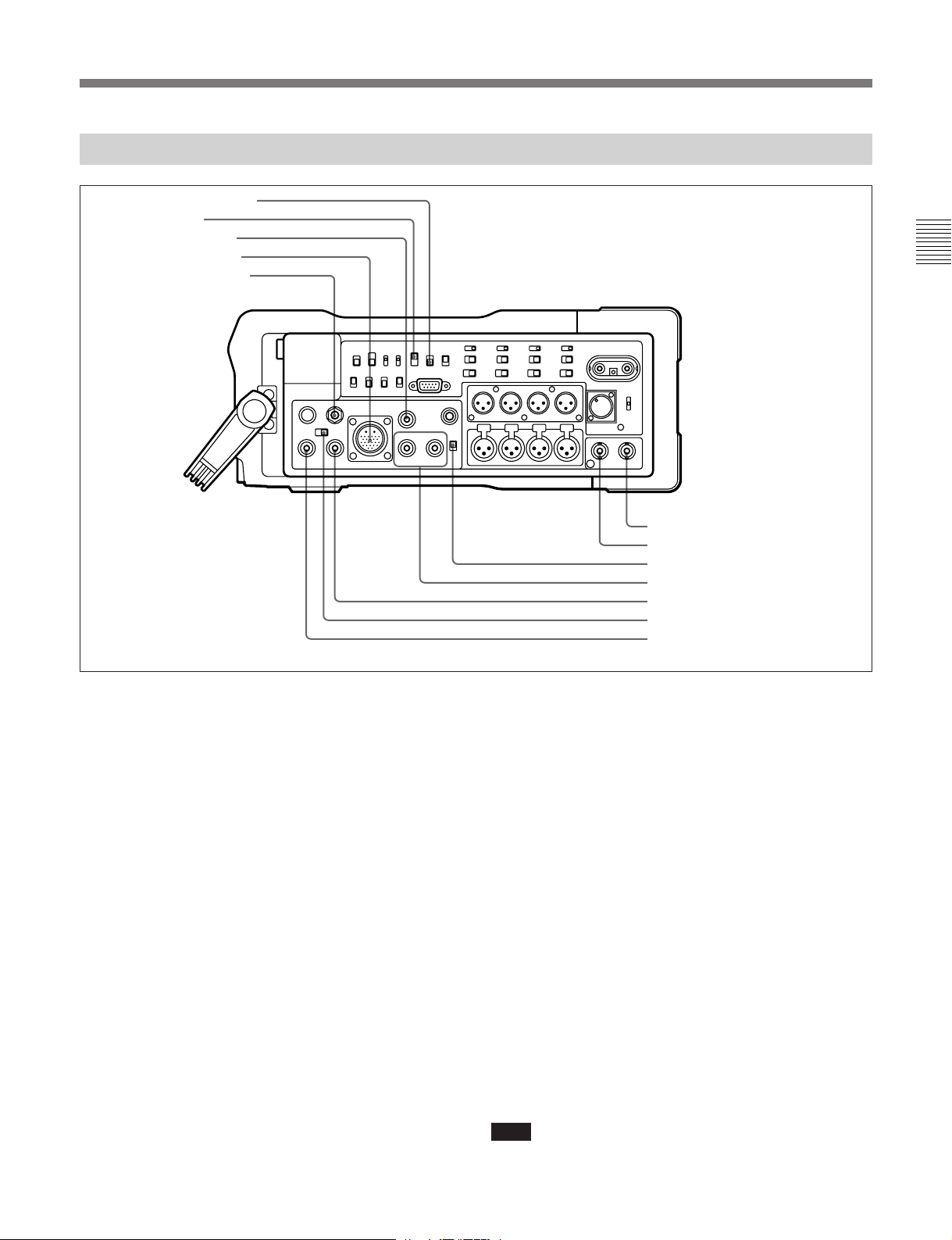
2-2-2 Video Connectors and Controls
1 COLOR FRAME switch
2 CONFI switch
3 SDI OUT connector
4 CAMERA connector
5 VIDEO LEVEL control
Chapter 2 Location and Function of Parts
6 TC OUT connector
7 TC IN connector
8 SUPERIMPOSE switch
9 VIDEO OUT 1 and 2 connectors
0 SDI IN connector
!¡ Video input selector switch
!™ VIDEO IN connector
Video connectors and controls
1 COLOR FRAME switch
This selects whether or not to enable color framing
during editing or playback.
ON: Enable color framing. Playback is always in
units of four (NTSC) or eight (PAL) fields.
OFF: Disable color framing. Playback is in units of
two fields.
2 CONFI (confidence) switch
This selects the mode for monitoring during recording.
Note that this switch applies to both video and audio.
ON: Monitor the simultaneously playback of the
recorded signals from the confidence heads.
ECC (Error Correcting Codes): Monitor the input
signals unchanged (in E-E mode). If a serious
error is detected while recording the signals, a
warning indication is given.
OFF: Monitor the input signals unchanged (in E-E
mode). The RF envelope is monitored during
recording, and if a fault occurs a warning
indication is given.
The ON setting results in the highest power
consumption, and the OFF setting the lowest. When
using the unit with a battery pack, set the CONFI
switch to the ECC or OFF position.
3 SDI (Serial Digital Interface) OUT connector
(BNC)
This outputs serial digital video and audio signals in
D1 format.
It is possible to switch this output on or off using item
“SDI OUT” in the <VIDEO 2> menu (see page 6-3).
4 CAMERA connector (26-pin)
Connect this to the multi-pin connector on the camera.
This interface carries video, audio and control signals
between the camera and the unit, and also supplies
power to the camera.
When the video input selector switch is in the
CAMERA position, the signals supplied to this
connector form the video input to the unit. When item
“CAMERA” in the <VIDEO 1> menu is set to
“AUTO” (see page 6-3), it is possible to input either
analog component video signals or D1 format serial
digital video and audio signals, depending on the type
of camera connected.
Note
When using other than a Sony camera, do not use the
“AUTO” setting: select “ANA” or “DIGI” as required.
Chapter 2 Location and Function of Parts 2-13

2-2 Connector Panel
5 VIDEO LEVEL control
If the composite signal input level to the VIDEO IN
connector is not a 1 Vp-p signal, use a screwdriver to
turn this control and adjust the input level. The range
of adjustment is ±3 dB. Normally leave this control at
the center detent position.
Chapter 2 Location and Function of Parts
It is not possible to adjust the input level for
component signals or serial digital video and audio
signals.
6 TC (time code) OUT connector (BNC)
Connect to the time code input connector of an
external device such as a time code reader or VTR.
The time code output depends on the operating state of
the unit, as follows:
Playback: playback time code
Recording: time code generated by the built-in time
code generator. When the time code on this unit
is locked to an external time code, the external
time code is output.
7 TC (time code) IN connector
Connect to the time code output connector of an
external device such as a time code generator or VTR.
Use this when locking the built-in time code generator
to the external time code.
8 SUPERIMPOSE switch
This selects whether or not to superimpose information
about the state of the unit (PLAY, FF, etc.) and time
code values on the composite video signal output from
the VIDEO OUT 2 connector.
ON: Superimpose information.
OFF: Do not superimpose information.
9 VIDEO OUT 1 and 2 connectors (BNC)
These connectors provide analog composite video
outputs. When the SUPERIMPOSE switch is in the
ON position, information about the state of the unit
and time code values are superimposed on the signal
output from the VIDEO OUT 2 connector.
0 SDI IN connector
Input serial digital video and audio signals in D1
format. When the video input selector switch is in the
SDI IN position, the signals supplied to this connector
form the video input to the unit.
!¡ Video input selector switch
The position of this switch determines the video input
to the unit.
VIDEO IN: composite video signal input to the
VIDEO IN connector
CAMERA: component video signal or serial digital
video signal input to the CAMERA connector
SDI IN: serial digital video signal input to the SDI
IN connector
The playback signal from this unit is synchronized to
the signal selected by this switch.
!™ VIDEO IN connector (BNC)
Input an analog composite video signal. When the
video input selector switch is in the VIDEO IN
position, the signals supplied to this connector form
the video input to the unit.
2-14 Chapter 2 Location and Function of Parts
 Loading...