

Sony Vaio SVZ131 Series Service Manual
Sony Condential
SVZ131 Series
SERVICE MANUAL
Ver 1-2011E
9-890-896-01
PERSONAL COMPUTER
Revision History
Design and specications are subject to
change without notice.
本機の仕様および外観は ,改良のため予告なく変
更することがありますが ,ご了承ください。
-2-
SVZ131 Series (9-890-896-XX)
Sony Condenti al
Informat ion in this document is su bject to
change without notice.
Sony, VAIO and CLIE are trademarks or registered trademarks of Sony. Microsoft, Windows,
Windows Media, Outlook, Bookshelf and other
Microsoft products are trademarks or registered
trad emarks of M icroso ft Corpor ation in the
United States and other countries . The wo rd
Bluetooth and the Bluetooth logo are trademarks
of Bluetooth SIG, Inc. AMD, the AMD logo, other
AMD product names and combinations thereof
are trademarks of Advanced Micro Devices, Inc.
Intel Inside logo, Pentium, Celeron and Core are
trademarks or registered trademarks of Intel Corp
oration. Transmeta, the Transmeta logo, Crusoe
Processor, the Crusoe logo and combinations
thereof are trademarks of Transmeta Corporation
in the USA and other countries. Graffiti, HotSync, PalmModem, and Palm OS are registered
trademarks, and the Hotsync logo and Palm are
trademarks of Palm, Inc. or its subsidiaries. (M)
and Motrola are trademarks of Motrora, Inc. Other
Motrola products and services with (R) mark like
Dragonball are the trademarks of Motrola, Inc.
All other names of systems, products and services
in this manual are trademarks or registered trademarks of their respective owners. In this manual,
the (TM) or (R) mark are not specified.
Caution Markings for Lithium/Ion Battery - The
following or similar texts shall be provided on
battery pack of equipment or in both the operating
and the service instructions.
CAUTION:
Danger of explosion if battery is
incorrectly replaced. Replace only with the same
or equivalent type recommended by the manufacturer. Discard used batteries according to the
manufacturer’s instructions.
CAUTION: The battery pack used in this device
may present a fireor chemical burn hazard if mistreated. Do not disassemble, heat above 60°C
(140°F) or incinerate. Dispose of used battery
promptly. Keep away from children.
CAUTION: Changing the back up battery.
Overcharging, short circuiting, reverse charging, multilation or incineration of the cells must
be avoided to prevent one or more of the following occurrences; release of toxic materials,
release of hydrogen and/or oxygen gas, rise in
surface temperature.
If a cell has leaked or vented, it should be
replaced immediately while avoiding to touch
it without any protection.
Service and Inspection Precautions
1. Obey precautionary markings and
instructions
Labels and stamps on the cabinet, chassis, and
components identify areas requiring special precautions. Be sure to observe these precautions,
as well as all precautions listed in the operating
manual and other associated documents.
2. Use designated parts only
The set’s components possess important safety
characteristics, such as noncombustibility and
the ability to tolerate large voltages. Be sure that
replacement parts possess the same safety characteristics as the originals. Also remember that the
mark, which appears in circuit diagrams and
parts lists, denotes components that have particularly important safety functions; be extra sure to
use only the designated components.
3. Always follow the original design
when mounting parts and routing
wires
The original layout includes various safety features, such as inclusion of insulating materials
(tubes and tape) and the mounting of parts above
the printer board. In addition, internal wiring has
been routed and clamped so as to keep it away
from hot or high-voltage parts. When mounting
parts or routing wires, therefore, be sure to duplicate the original layout.
4. Inspect after completing service
After servicing, inspect to make sure that all
screws, comp onents, and wiring have been
returned to their original condition. Also check
the area around the repair location to ensure that
repair work has caused no damage, and confirm
safety.
5. When replacing chip components...
Never reuse components. Also remember that
the negative side of tantalum capacitors is easily
damaged by heat.
6. When ha ndling fl ex ib le print
boards...
The temp erature of the solder ing-ir on tip
should be about 270°C.
z
z
z
z
z
Do not apply the tip more than three times to
the same pattern.
Handle patterns with care; never apply force.
Caution: Remember that hard disk drives are
easily damaged by vibration. Always handle
with care.
ATTETION AU COMPOSANT AYANT
RAPPORT
À LA SÉCURITÉ!
LES C OMPO SANT S IDENT IFÉS PAR UNE
M AR Q UE S U R L ES D IAG R AM M ES
SCHÉ MATIQUES ET LA LISTE DES PIÈCES
SONT CRI TIQUE S POU R LA SÉCURITÉ DE
FON CTIONNEMENT. NE REMPL ACER CES
COMPOSANTS QUE PAR DES PIÈSES SONY
DONT LES NUMÉROS SONT DONNÉSDANS
CE MANUE L OU DAN S LE S SU PPÉMENTS
PUBLIÉS PAR SONY.
The components identified by mark contain
confidential information.
Strictly follow the instructions whenever the
components are repaired and/or replaced.
-3-
SVZ131 Series (9-890-896-XX)
Sony Condenti al
TABLE OF CONTENTS
Section Title Page
CHAPTER 1. BLOCK DIAGRAM
................................................................................................1-1
(to 1-1)
CHAPTER 2. FRAME HARNESS DIAGRAM
........................................................................2-1
(to 2-1)
CHAPTER 3. EXPLODED VIEWS
Main Section
MS-1 ........................................................................................................................................................3-2
LCD
L-1 ...........................................................................................................................................................3-3
Accessories
A-1 ...........................................................................................................................................................3-4
Accessories (DOCKING STATION)
A-2 ...........................................................................................................................................................3-5
Accessories (STAND)
A-3 ...........................................................................................................................................................3-6
(to 3-6)
CHAPTER 4. OTHERS
4-1. Note for WAN Board Replacement .......................................................................................................4-1
4-2. Note for WiMAX Board Replacement ..................................................................................................4-2
(to 4-2)
History of the changes is shown as the "Revision
History" at the end of this data.
変更履歴は、
“ Revision History ”
として、 本データ末に
記載してあります。
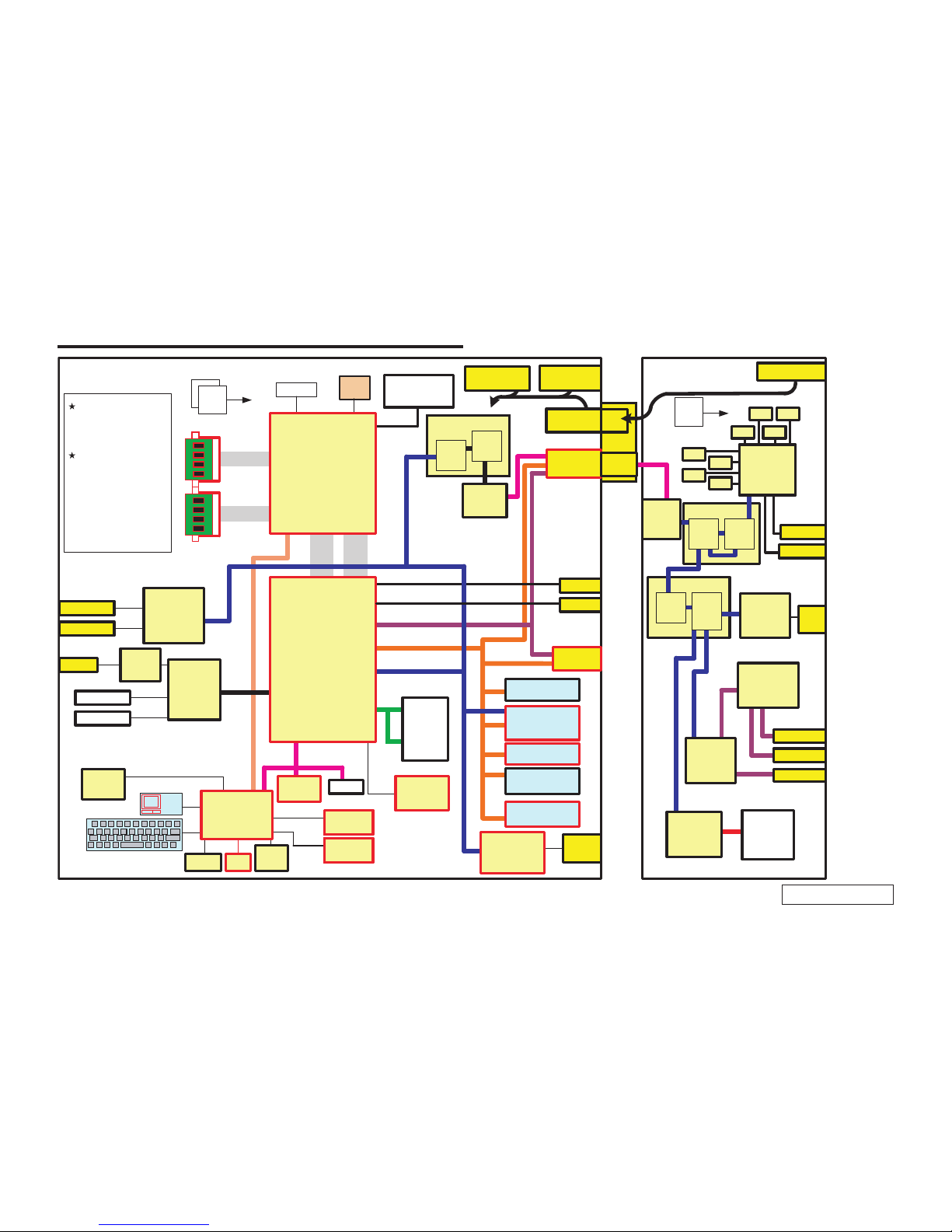
1-1
CHAPTER 1.
BLOCK DIAGRAM
SVZ131 Series (9-890-896-XX)
Sony Condenti al
(END)
8
01
31
1
4
PECI
IMVP7.0
VR
XDP
USB
USB3.0
2
1
PCI Express
SATA
0
1
LPC
Azalia
Touch
PAD
BUTTONs
LID
Button/SW
Power
ASSIST VAIO Web
-
LEDs
Power Cherge
Keyboard -
num/ caps/ scr lk
(Except EC)
SSD Wireless Camera MS, SD -
Memory
NAF
TACH
FDI DMI
2
9
PCle[8:7]
11
USB 14ports
EHCI #1:8ports
XHICI ports
EHCI #2:6ports
PCI Express
8ports
SATA
6ports
NAF
1
0
FAN
0
21
PCIex4: 0-3
Processor
Intel
Ivy Bridge-QC/DC
eDP
Block Diagram
Docking Station
DDR3 1600 MHz
DDR3 1600 MHz
LCD 13.1"
1920x1080
1600x900
1st BatteryCN2nd Battery
CN
DC jack
DC jack
DC
Plug
Eagle Ridge
Eagle Ridge
Eagle Ridge
PCIe
Bridge
CIO
Bridge
CIO
Bridge
Optional
Module
CIO
Bridge
GbE
Controller
Realtek
RTL8111E
USB2.0
Hub
NEC
uPD720114GA
USB3.0
Host
NEC
uPD720200A
PCIe-SATA
Bridge
Marvell
88SE6121
PCIe
Bridge
PCIe
Bridge
OE
Module
RGB
RGB
USB2.0
USB2.0
USB3.0
ODD
HDMI
HDMI
USB3.0
/Charge
Optional
CN
Optional CN
/USB3.0
Memory Card
Controller Chip
Magic Gate
Realtek
RTS5209
Digital
NCHP
CS47L01
Internal SP
Internal MIC
Normal or
Back lit KBD
Audio Codec
w/ HWEQ
Realtek
ALC275
EC
smsc
MEC1621
Ambient
Light
Sensor
MS
SD
HP
PCH
Intel
Panther Point
SSD
TPM
Infineon
FW3.19
DEBUG
Thermal
diode
(For Memory)
(For AOAC)
Thermal
diode
LEDs
SPI Flash
64Mbit
FP or non
AuthenTec AES1660
Camera or non
WLAN/WiMAX
GbE
Controller
Realtek
RTL8111F
WAN or non
Gobi3000(EU,AP)
LTE(EU,JP,RU)
BT
RJ-45
VRAM:1GB
(64M x 16 , 8 pcs)
VRAM VRAM
VRAM
VRAM
VRAM
VRAM
VRAM
VRAM
AMD
WHISTLER_XT
RJ-45
BU22
Ricoh R5U8710
Kilmer Peak/
Jackson Peak2/Puma Peak
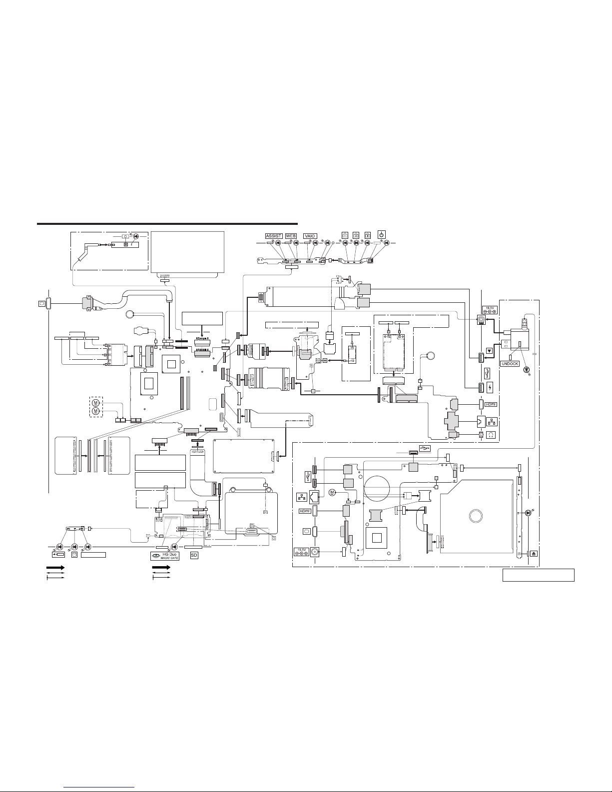
CHAPTER 2.
FRAME HARNESS DIAGRAM
2-1
SVZ131 Series (9-890-896-XX)
Sony Condenti al
(END)
From boardto connector(direct connection)
Harness (connectorat bothend)
Harness (solderedat oneend)
基板からコネクタへ(ダイレクト接続)
ハーネス(両端がコネクタ付き)
ハーネス(一方が半田付け)
HD CAMERA
MODULE
L Side
Bottom
R Side
MN-LI RECHARGEABLE
BATTRY
FPC-296
BUTTON
FINGER PRINT
SENSOR
FP Model
BACK LIGHT
KB Model
Docking Station Model
FPC-224
FPC-232
FPC-282
FPC-283
Bottom
Bottom
HARNESS DC JACK
FFC (MBX257-SWX386)
FFC
(IFX615-LEX97)
FFC (IFX615-TP)
FPC-225
LCD
MAIN
BOARD
Side A
MM-19
BOARD
Side A
MM-19
BOARD
Side A
IFX-615
BOARD
Side A
IFX-612
BOARD
Side A
IFX-613
BOARD
Side A
SWX-386 BOARD
Side A
LEX-97
BOARD
Side A
KEYBOARD
UNIT
BATTERY
2nd
BATTERY
TOUCH PAD
SSD
FUN UNIT
Front
SPEAKER L
SPEAKER
R
JUMPER CABLE WITH OE MODULE
Top
WIRELESS
Camera Model
HARNESS
Front
N.C.
BATTERY
OFF BUTTON
MIC
HARNESS
(DC JACK)
L Side
Rear
HARNESS (RJ-45)
IFX-578
BOARD
Side A
R Side
POWER
LAMP
FUN
UNIT
LEX-98 BOARD
Side A
ODD
FFC (IFX578-LEX98)
FPC-229
DOCKING
CONNECTOR
IN USE
BT
MODULE
Ext BT Model
BLU
BT ANTENNA
WIRELESS-LAN,
WLAN/WiMAX COMBO,
WLAN/BT COMBO
CARD
ANTENNA (WiMAX/WLAN)
WLAN 3rd Model
BLK
GRY
WHT
1
3
2
SUB 3rd MAIN
Rear
SIM CARD
WAN Model
WAN Model
WWAN ANTENNA
MINI
CARD
BLK
MAIN AUX
GRY
 Loading...