

Sony URX-S03D Operating Instructions Manual

UHF Synthesized
4-590-341-11 (1)
Diversity Tuner
Operating Instructions
URX-S03D
© 2016 Sony Corporation

Table of Contents
Features .......................................................3
Parts Identification......................................4
Preparation ..................................................5
Attaching to a Camcorder............................. 5
Using Wireless Adapters .............................. 5
Settings ........................................................5
Setting the Receive Channel......................... 5
Searching for Available Channels within a
Group (Clear Channel Scan) ............... 6
Searching for Active Channels within a Group
(Active Channel Scan) ........................ 6
Setting the Compander Mode ....................... 6
Using the Squelch Function.......................... 7
Using the Infrared Communication
Function............................................... 7
Menu Displays and Detailed Settings........9
Menu Structure and Hierarchy...................... 9
Basic Menu Operations................................. 9
UTILITY Menu ............................................ 9
RX (tuner) 1/2 Menu .................................. 10
Error Messages .........................................11
Troubleshooting ........................................12
Important Notes on Use............................13
Usage and Storage ...................................... 13
Cleaning...................................................... 13
Specifications............................................13
2

Features
The URX-S03D UHF Synthesized Diversity Tuner is a
two-channel slot-in wireless tuner that can be used in
conjunction with Sony professional camcorders and
optional wireless adapters.
Two-channel camcorder-slot-in receiver
The unit is a camcorder slot-in receiver that supports
systems that include two transmitters operating
simultaneously. If your camcorder does not support slotin mounting, you can attach the unit to an optional DWA01D or DWA-F01D wireless adapter.
XDCAM compatibility
The two channels of digital signals processed by the
unit’s DSP can be sent directly to the camcorder via the
15-pin D-sub connector. The RF/AF levels of each
wireless microphone can also be viewed via the
camcorder’s viewfinder.
HDCAM compatibility
The units’ single channel of analog output signals can be
sent directly to the camcorder via the 15-pin D-sub
connector. Two different audio signals sent from two
transmitters can also be mixed for output as a singlechannel audio signal.
The RF/AF levels of each wireless microphone can also
be viewed via the camcorder’s viewfinder. When both
channels are enabled, channel 1 is displayed. When only
one channel is enabled, that channel is displayed.
Built-in infrared communication function
When operating in conjunction with UWP-D series
transmitters, the frequency and compander mode settings
configured on the unit can be sent using the infrared
communication function, allowing you to complete
channel configurations quickly.
Sturdy construction for use outdoors
Designed to withstand rough outdoor conditions with its
solid dust-proof body, the unit meets JIS II drip-resistance
standards when mounted on a camcorder with its
antennas attached.
Switchable squelch function
A squelch function that can be turned on or off depending
on the situation is available.
True diversity system
The unit is equipped with two lines of reception for each
channel that can receive signals from the transmitter
simultaneously. The true diversity system determines the
stronger of the two antennas signals and selects it
automatically, achieving highly stable reception with
minimal interruption and noise across a wide area.
Compatibility with Sony analog wireless
microphones
The built-in DSP enables digital companding for highquality audio transmissions. Switching to compander
mode allows operation in conjunction with Sony analog
wireless microphone system (UWP series and WRT
series) transmitters.
High-visibility display
The area of the display screen is twice that of previous
models, providing enhanced visibility. The built-in
backlight also allows easy settings changing in even the
darkest of shooting locations.
Channel scanning
Clear channel scanning for detecting unoccupied
channels and active channel scanning for detecting used
channels allow you to quickly assess the situation at a
location and configure the appropriate channel.
3
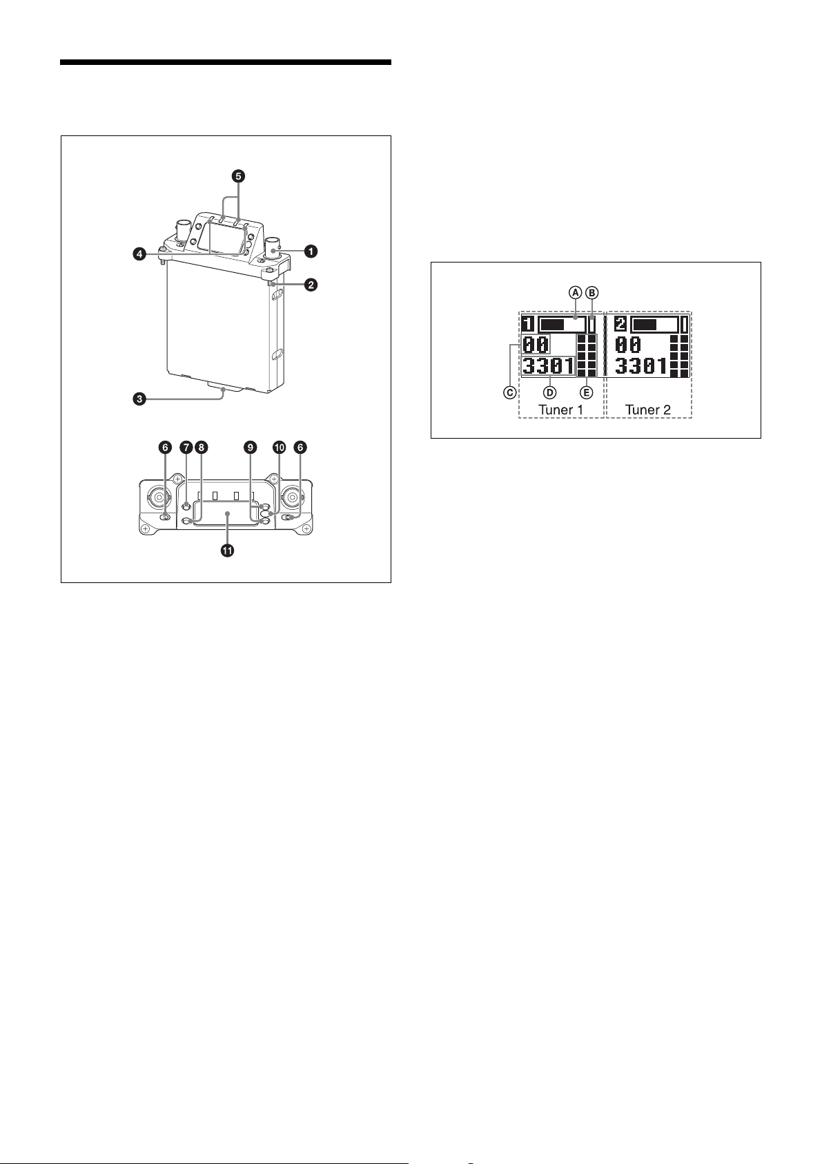
Parts Identification
h SET button
Changes the item to be set or enters the selected function
or parameter value.
i + or – button
Use to select a function or value.
j Infrared transmission port
Transmits the frequency and compander mode settings
configured on the unit to the transmitter.
k Display section
Meter display
A Audio input level meter
Indicates the input signal level.
a Antenna connector (BNC type)
Connect the supplied antenna here.
b Mounting screw
Use to attach the receiver to a camcorder or wireless
adapter.
c Accessory connector (15-pin D-sub)
Use to connect the receiver to a camcorder or wireless
adapter. Power, audio, and control signals are sent
through this connector.
d POWER indicator
Lights up green when the power is on.
The POWER1 and POWER2 indicators indicate the
power status of tuner 1 and tuner 2, respectively.
e RF (radio frequency) indicators
Indicate the RF input level of tuner 1 and tuner 2.
On in green: 25 dBµ or more
On in red: 15 dBµ to 25 dBµ
Off: Less than 15 dBµ
0 dBµ = 1 µV
EMF
B Peak indicator
Warns of excessive input by lighting up when the signal
is 3 dB below the level at which distortion begins.
C Group display
Displays the name of the receive group that is configured.
D Channel display
Displays the name of the receive channel that is
configured.
E RF level meter
Indicates the RF input level. The number of segments that
light up depends on the input level.
5 segments lit: 50 dBµ or higher
4 segments lit: 40 to 49 dBµ
3 segments lit: 30 to 39 dBµ
2 segments lit: 20 to 29 dBµ
1 segment lit: 10 to 19 dBµ
All segments off: 10 dBµ or less
f POWER switches
Turn tuner 1 and tuner 2 on or off individually.
g MENU button
Selects the displayed menu.
4
Preparation
Settings
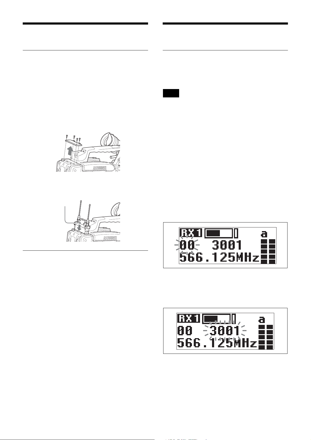
Attaching to a Camcorder
This receiver can be inserted into a slot provided on
compatible Sony camcorders.
1
Remove the cover from the slot for the wireless
receiver on the camcorder, and insert the receiver into
the slot.
To avoid inserting the receiver in the wrong direction,
confirm the location of the mounting screws before
inserting the wireless receiver.
2
After inserting the receiver completely into slot,
securely fasten the four mounting screws.
Receiver
Setting the Receive Channel
For details about the channel groups and channels that can
be selected, refer to the “Frequency List” on the
CD-ROM.
Note
To prevent interference and noise, beware of the
following.
• Do not use multiple transmitters that have been set to
the same channel at the same time.
• When using two or more channels at the same time,
always configure different channels within the same
group.
• Keep all transmitters and receivers at least 3 m away
from each other.
1
Set the POWER 1 or POWER 2 switch to ON.
2
Press the MENU button to display the RX1 or RX2
menu, and press the + or – button to display the GP/
CH screen.
3
Press and hold the SET button for 1 second or longer.
Using Wireless Adapters
Attaching the unit to an optional DWA-01D or DWAF01D wireless adapter allows you to use the unit as a
portable wireless receiver.
For details on attaching the unit, refer to the operating
instructions supplied with the DWA-01D or DWA-F01D.
The channel group display starts flashing.
4
Use the + or – button to select the desired group
name, then press the SET button.
The channel group is set, and the channel number
display starts flashing.
5
Use the + or – button to select the desired channel
number, then press the SET button.
The displays stops flashing and the desired channel is
set.
5
 Loading...