

Page 1

Diversity Tuner
Module
4-567-049-01 (1)
Operating Instructions
Before operating the unit, please read this manual thoroughly
and retain it for future reference.
URX-M2
© 2014 Sony Corporation
Page 2

Table of Contents
Configuration of the Packages ..... 3
Features .......................................... 3
Parts Identification ........................ 4
Power Supply ................................. 5
Attachment and Installation
Procedures ...................................... 5
Installing a diversity tuner module
(URX-M2) ............................... 5
Operation ....................................... 7
If noise is heard ....................... 7
Tuner Settings ................................ 8
Setting the reception
channel ..................................... 8
Selecting the channels on multiple
tuners automatically ................ 9
Transmitter Settings ................... 10
System Configurations................ 12
Error Messages............................ 14
Troubleshooting........................... 15
Important Notes on Use .............. 17
On usage and storage ............. 17
On cleaning ............................ 17
Specifications ............................... 18
Table of Contents
2
Page 3
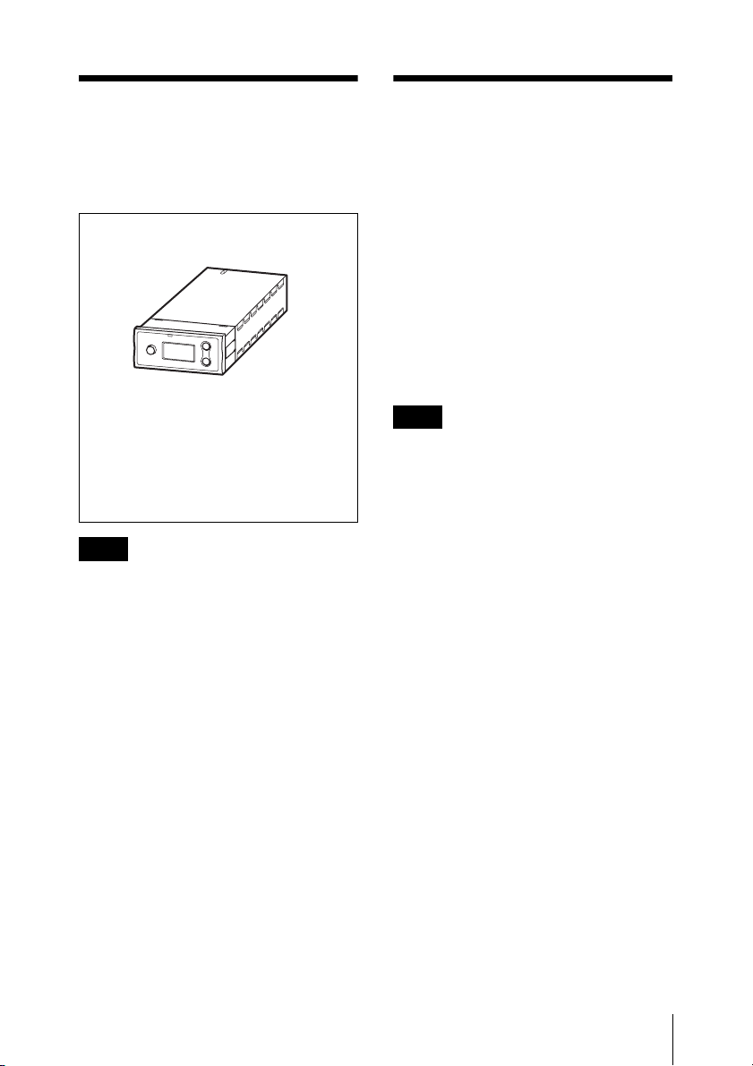
Configuration of the Packages
Diversity tuner module (URX-M2) (1)
Supplied accessories
Operating Instructions (1)
CD-ROM (1)
Warranty card (1)
(for U30 and U42 models)
Note
This manual is intended specifically for the
URX-M2 tuner.
When using the tuner in conjunction with
the UTX-M03 transmitter, be sure to read
the configuration instructions found in the
operating instructions for the UWP-D series
together with this manual.
Features
This tuner (diversity tuner module
(URX-M2)) is a tuner module that can be
incorporated into an MB-X6 Tuner Base
Unit, SRP-X500P Powered Mixer, or
similar device.
The combination of the diversity tuner
module (URX-M2) and a transmitter (not
supplied) used in conjunction with a
powered mixer, for example, allows use in
AV (audio visual) presentations and smallscale PA (public address) systems.
Note
The unit is not compatible with WRT series
transmitters.
Configuration of the Packages / Features
3
Page 4
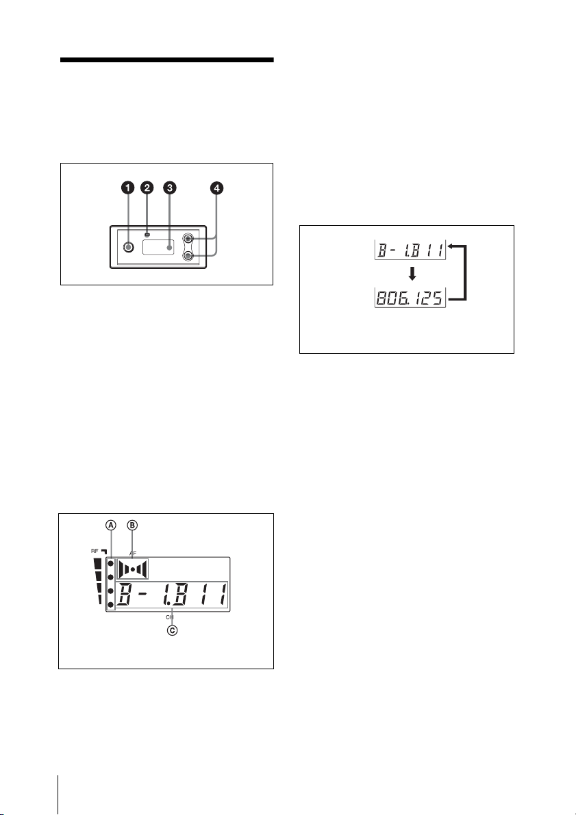
Parts Identification
a SET button
Press to change and enter display
parameters.
For details, see “Tuner Settings” on page 8.
b RF (radio frequency) indicator
The color indicates the strength of the RF
input signal.
On (green): RF input is 25 dBµ
Off: RF input is less than 25 dBµ
1)
or more.
1)
.
B AF (audio frequency) indication
Appears whenever the output audio signal
is stronger than the reference level.
C GP (group)/CH (channel) indication
Shows the reception channel group and
channel number. Each time you press the
SET button, the channel indication changes
as follows.
For details, see“Tuner Settings” on page 8.
Reception
channel group
and number
Reception
frequency
The channel/frequency indications for
U30 model are shown.
Press
the
SET
button.
d + (+ selection) / – (– selection/reset)
buttons
Press these buttons to set the reception
channel and frequency.
1) 0 dBµ = 1 µVEMF
c Display section
The channel indication (C) for
U30 model is shown.
A RF (radio frequency) indications
The number of dots indicates the RF input
level.
Parts Identification
4
Page 5

Power Supply
Attachment and
Installation
When incorporated into another component
(e.g., MB-X6, SRP-X500P, etc.), the tuner
module draws its power from that
component.
For details on the power supp ly to the diversity tuner
module, refer to the operating instructions of the
component in which the diversity tuner module is
installed.
Procedures
This section describes how to install the
diversity tuner module onto an MB-X6
Tuner Base Unit or SRP-X500P Powered
Mixer.
Installing a diversity tuner module (URX-M2)
Notes
• Before installing the diversity tuner
module (URX-M2), make sure the unit
into which the tuner module will be
installed is turned off. Do not install or
uninstall the tuner module while the unit
into which the tuner module will be
installed is turned on, as this may result in
malfunction of the tuner module or cause
noise.
• Do not put your fingers on the connectors
on the rear panel of the tuner module or
into the slot on the unit into which the
tuner module will be installed.
• Keep the tuner module away from static
electricity.
Power Supply / Attachment and Installation Procedures
5
Page 6
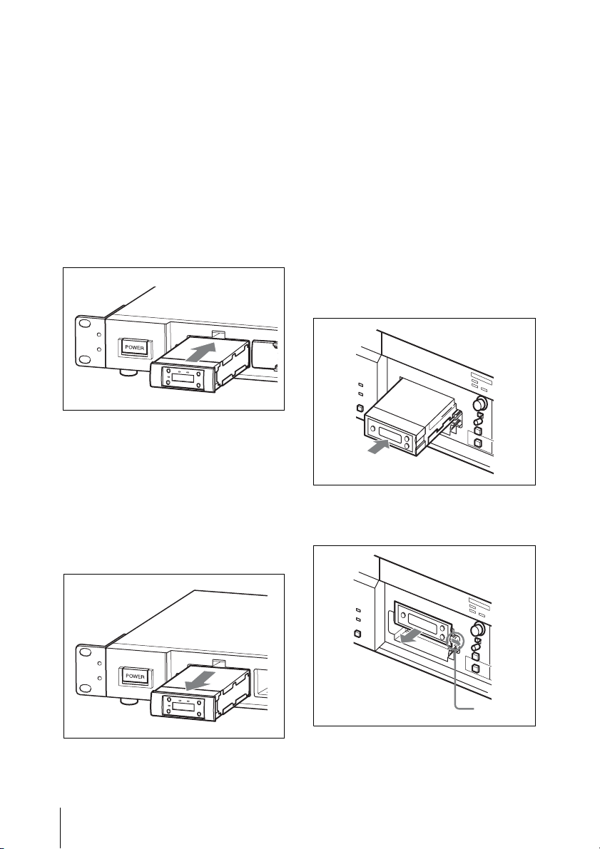
To install a diversity tuner
module (URX-M2) into the
optional MB-X6 Tuner Base
Unit
The MB-X6 Tuner Base Unit (not supplied)
can accommodate up to 6 diversity tuner
modules (URX-M2).
For details on installation procedure, refer to the
Operating Instructions supplied with the MB-X6.
Hold the tuner module by the side and insert
it into the slot until you hear a click.
To install two or more tuner
modules
Before installing the tuner modules, detach
the necessary number of blank panels from
the front cover of the MB-X6.
To uninstall a tuner module
After removing the front cover of the
MB-X6, hold the tuner unit by the top and
bottom, then pull it out of the slot.
To install a diversity tuner
module (URX-M2) into the
optional SRP-X500P Powered
Mixer
The SRP-X500P Powered Mixer (not
supplied) can accommodate up to two
diversity tuner modules (URX-M2).
For details on installation procedure, refer to the
Operating Instructions supplied with the
SRP-X500P.
Remove the protection panel (large) from
the SRP-X500P. Inspect the top and bottom
sides of the diversity tuner module and
insert it into the slot.
To uninstall the tuner module
Pull the latch securing the tuner module to
the side and pull out the tuner module.
Attachment and Installation Procedures
6
Latch
Page 7

Operation
1 Make all necessary connections on the
tuner.
For examples of connections, see “System
Configurations” on page 12.
2 Turn on the tuner.
The parameters that were in the display
section when the tuner was last turned
off appear again.
Note
Noise will be produced when the tuner
is turned on. Before turning on the
tuner, turn down the volume of the
equipment connected to the tuner.
3 Set the reception channel on the tuner.
Switch the channel on the tuner with
the transmitter turned off and select the
channel where the RF indicator does
not turn on.
For details on setting the reception channel,
see “Setting the reception channel” on page 8.
4 Set the transmission channel on the
transmitter, and then turn off the unit.
For details on setting the transmission
channel, refer to the operating instructions for
the transmitter.
If noise is heard
Depending on the environment where the
unit is installed, external noise or radio
waves may disrupt transmission on certain
channels.
When selecting a channel under these
circumstances, turn off the transmitter.
Then, on the tuner, select a channel for
which the RF indicator does not light up
(i.e., a channel free from noise or radio
wave interference). Set the same channel on
the transmitter.
Note
To prevent interference or noise, please
take the following precautions.
• Do not use two or more transmitters with
the same wireless channels.
• When operating two or more UWP series
packages simultaneously, set each
package to a different channel within the
same channel group.
• Keep the reception antenna and the
transmitter separated more than 3 meters
(9 feet 11 inches).
• When operating two or more UWP series
packages simultaneously with different
channel groups, make sure that they are at
least 100 meters (330 feet) apart, if they
are used within clear sight of each other.
(The actual distance may differ
depending on the circumstances.)
5 Turn on the transmitter.
Operation
7
Page 8

Tuner Settings
Setting the reception channel
Refer to the pdf files “Sony Wireless Microphone
System Frequency List” on the supplied CD-ROM
for details on the selectable channel groups and
channels.
1 Press down the SET button for more
than one second.
Keep pressing the SET button until the
display section parameters start to
flash.
2 Press the SET button repeatedly until
the channel group and the channel
number indications appear.
The channel group indication starts to
flash.
4 When the desired channel group
number appears, press the SET button.
The selected group is entered.
The right four digits start to flash to
allow the selection of the channel
number.
5 Press the + or – button to select the
channel number.
The channel indication changes in the
order shown in the tables in the pdf
files “Sony Wireless Microphone
System Frequency List” on the
supplied CD-ROM.
Example: When the channel group 00 is
selected
3 Press the + or – button to select the
channel group.
Pressing the + button cycles the
indication in the order shown in the
tables in the pdf files “Sony Wireless
Microphone System Frequency List”
on the supplied CD-ROM.
Pressing the – button cycles the
indications in the opposite direction.
Hold down the + or – button to change
the channel group faster.
Tuner Settings
8
6 When the desired channel number
appears, leave the tuner for about 10
seconds or press down the SET button
for more than one second.
The selected channel number stops
flashing and the selection is stored in
memory.
Page 9

To select the channel by
frequency indication
1 Press the SET button for more than one
second.
Keep pressing the SET button until the
display section parameters start to
flash.
2 Press the SET button repeatedly until
the frequency indication appears and
starts flashing.
3 Press the + or – button to select the
frequency.
4 When the desired frequency appears,
leave the tuner for about 10 seconds or
press down the SET button for more
than one second.
The selected channel number stops
flashing and the selection is stored in
memory.
Notes
• Even when you are setting the reception
channel, the tuner can be used to receive
signals.
• Do not remove the batteries while setting
the reception channel. If they are
inadvertently removed, re-insert them
immediately and redo the procedure
“Setting the reception channel” from
step 1.
• Make sure that the selected channel is the
same on the transmitter and tuner being
used in the same system.
• If you turn off the tuner and then
immediately turn it on right after setting
the reception channel, the unit may not
operate normally. Wait a few seconds
before turning it on again.
Selecting the channels on multiple tuners automatically
When multiple diversity tuner modules
(URX-M2) are installed into the MB-X6 to
perform simultaneous multiple-channel
operation, select the channel group on the
tuner module installed into the slot 1 of
the MB-X6, then all the tuner modules
installed into the MB-X6 can be set to
different channels within the selected
channel group.
1 Turn off all the microphones and
transmitters.
2 Select the channel group on the tuner
module installed into the slot 1 of the
MB-X6.
3 After confirming that the channel
group indication has stopped flashing
(about 10 seconds after you have
selected the channel group), keep
pressing the + button on the tuner
module installed into the slot 1 of the
MB-X6.
All the tuner modules installed into the
MB-X6 are set to the available
channels within the selected channel
group.
After the automatic detection and
selection of available channels finish,
you can change the group and channel
on each tuner module manually.
Tuner Settings
9
Page 10

Notes
• Do the automatic detection and selection
of available channels with the channel
group other than channel group 00.
• When there are unavailable channels due
to extraneous radio wave and the channel
could not be selected on some tuner
modules, “NO CH” appears on the
display of those tuner modules. If this
happens, select the channel group with no
interference from extraneous radio wave,
and repeat the procedure above.
Transmitter Settings
When using the URX-M2 in conjunction
with the UTX-M03, be sure to configure the
settings on the UTX-M03.
For details on the channel groups and channels that
can be used during use with this unit, refer to the
Frequency List on the CD-ROM supplied with the
unit.
Selecting the frequency band
(BAND) (CE38 models only)
1 Press and hold the SET button, and
press the POWER/MUTING button to
turn the power on.
2 Use the + or – button to display
BAND.
3 Press and hold the SET button for
1 second or longer.
Transmitter Settings
10
4 Use the + or – button to select the
transmission frequency band.
5 Press the SET button to confirm the
setting.
Page 11

Setting the menu display
mode (MENU MODE)
1 Press and hold the SET button, and
press the POWER/MUTING button to
turn the power on.
2 Use the + or – button to display MENU
MODE.
3 Press and hold the SET button for
1 second or longer.
4 Use the + or – button to select
ADVANCED.
5 Press the SET button to confirm the
setting.
Setting the compander mode
(COMPANDER)
1 Press and hold the SET button, and
press the POWER/MUTING button to
turn the power on.
2 Use the + or – button to display
COMPANDER MODE.
3 Press and hold the SET button for
1 second or longer.
4 Use the + or – button to select UWP.
5 Press the SET button to confirm the
setting.
Transmitter Settings
11
Page 12

System Configurations
Note
Production of the peripheral and relating devices may have been discontinued. Upon selecting
the devices to be used with this product, consult your nearest Sony representative or the dealer
from whom you purchased the product.
Sample configuration for AV presentations
To DVD player, PC, or
VTR, etc.
AN-820A UHF
antenna
SRP-X500P Powered Mixer
Diversity tuner
module (URX-M2)
Hand-held
microphone
(UTX-M03)
1 XLR cable or pin cable
2 BNC cable
System Configurations
12
Page 13

Sample configuration of a PA system
Hand-held microphone
(UTX-M03)
To DVD player, PC, or
VTR, etc.
AN-820A UHF
antenna
WD-850 Antenna Divider
MB-X6 Tuner Base Unit
SRP-X100 Audio Mixer
Diversity tuner
module (URX-M2)
SRP-X500P Powered Mixer
1 BNC cable
2 XLR cable
3 XLR cable or pin cable
Diversity tuner
module (URX-M2)
System Configurations
13
Page 14

Error Messages
When a problem occurs, one of the following error messages may appear on the display.
Messages Meanings Remedy
Err 01 An error has occurred in the backup
memory data.
Err 02 The PLL synthesized circuit is
abnormal.
Contact your Sony dealer.
Restart the unit. If the message
appears again, contact your Sony
dealer.
14
Error Messages
Page 15

Troubleshooting
If you have any problem using the unit, use the following checklist.
Should any problem persist, consult your Sony dealer.
Symptom Meanings Remedy
The channel cannot
be changed.
There is no sound. The channel setting on the
The sound is weak. The attenuation level on the
An attempt was made to
change the channel by
pressing the SET button only.
transmitter is different from
that on the tuner.
The RF indicator on the tuner
does not turn on.
The tuner module is installed
into/uninstalled from the
MB-X6/SRP-X500P while the
MB-X6/SRP-X500P is turned
on.
The transmitter is not
transmitting signals, or the
transmission output is weak.
The compander mode
setting on the transmitter is
different from that on the
tuner.
The transmitter is muted.
transmitter is too high.
The volume on the amplifier
or mixer is low.
The compander mode
setting on the transmitter is
different from that on the
tuner.
Restart the unit while holding
down the SET button. Then
change the channel with the +
and – buttons.
Use the same channel setting on
both the transmitter and tuner.
Confirm that the transmitter is
turned on.
Turn off the MB-X6/SRP-X500P.
Then, turn it on again.
Confirm that the transmitter is
turned on. Alternatively, reduce
the distance between the
transmitter and tuner.
Configure the transmitter’s
compander mode to a setting that
matches this unit.
Press the POWER/MUTING
button on the transmitter to
release the muted state.
The input level of the transmitter
is low. Press the – button on the
transmitter in attenuation level
setting mode to decrease the
attenuation level.
Adjust the volume.
Configure the transmitter’s
compander mode to a setting that
matches this unit.
Troubleshooting
15
Page 16

Symptom Meanings Remedy
There is distortion
in the sound.
There is sound
interruption or
noise.
The RF indications
on the tuner appear
(the RF indicator
lights up) even
when the
transmitter is off.
The attenuation level of the
transmitter is too low.
The transmitter and the tuner
are set to different channels.
The compander mode
setting on the transmitter is
different from that on the
tuner.
The transmitter and the tuner
are set to different channels.
Two or more transmitters are
set to the same channel.
The transmitters are not set
to the channels within the
same channel group.
Two or more UWP series
packages are operated at
close channels.
Jamming radio waves are
being received.
The input level of the tuner is
extremely high. Press the + button
on the transmitter in attenuation
level setting mode to raise the
attenuation level.
Set the transmitter to the same
channel.
Configure the transmitter’s
compander mode to a setting that
matches this unit.
Set the transmitter to the same
channel as the tuner.
Set each transmitter to a different
channel.
The channel plan which the unit
uses is set so that no signal
interference occurs when 2 or
more transmitters are used
simultaneously. Set each
transmitter to a different channel
within the same channel group.
• Select channels within the
same channel group (except
channel group 00).
• Use the channels at least
2-channel intervals (250 kHz).
Locate the channel group that is
unaffected by jamming radio
waves and use that channel
group.
16
Troubleshooting
Page 17

Important Notes on Use
On usage and storage
• Operating the unit near electrical
equipment (motors, transformers, or
dimmers) may cause it to be affected by
electromagnetic induction. Keep the unit
as far from such equipment as possible.
• The presence of the lighting equipment
may produce electrical interference over
the entire frequency range. Position the
unit so that interference is minimized.
• To avoid degradation of the signal to
noise ratio, do not use the unit in noisy
places or in locations subject to vibration,
such as the following:
- near electrical equipment, such as
motors, transformers or dimmers
- near air conditioning equipment or
places subject to direct air flow from
an air conditioner
- near public address loudspeakers
- where adjacent equipment might
knock against the tuner
Keep the unit as far from such equipment
as possible or use buffering material.
To prevent electromagnetic
interference from portable
communication devices
The use of portable telephones and
other communication devices near
the unit may result in malfunction and
interference with audio signals. It is
recommended that portable
communication devices near the unit
be turned off.
On cleaning
Clean the surface and the connectors of the
unit with a dry, soft cloth. Never use
thinner, benzene, alcohol or any other
chemicals, since these may mar the finish.
Important Notes on Use
17
Page 18

Specifications
Type of reception
True diversity method
Oscillator type
Crystal-controlled PLL synthesizer
Reception frequencies
Model available in USA: 566 to
590 MHz (U30 model), 638 to
662 MHz (U42 model)
Model available in Europe: 566 to
590 MHz (CE33 model), 606 to
630 MHz (CE38 model), 638 to
662MHz (CE42model)
Model available in Korea:
925.125 MHz to 931.875 MHz
(KR Model)
Model available in Thailand and
Taiwan: 794 to 806 MHz
(E model)
Operating frequency band
Model available in USA and
Europe: 24 MHz BW
Model available in Thailand and
Taiwan: 12 MHz BW
Signal-to-noise ratio
60 dB or more
De-emphasis
50 µs
Reference deviation
±5 kHz
Distortion
1.0% or less at 1 kHz modulation
Tone signal
32 kHz
Indicator
RF input level
Operating temperature
0°C to 50°C (32°F to 122°F)
Storage temperature
–20 °C to +55 °C (–4 °F to +131 °F)
Squelch level
25 dBµ
Display
Channel, frequency
Reference deviation
±5 kHz (at 1 kHz modulation)
Frequency response
50 Hz to 18 kHz
Dimensions
Unit: mm
57 × 26 × 121 mm
1
1
(2
/
× 1
4
7
/
× 4
/
16
inches)
8
(w/h/d)
Mass Approx. 150 g (5.3 oz)
Design and specifications are subject to
change without notice.
18
Specifications
Page 19

Note
Always verify that the unit is operating
properly before use. SONY WILL NOT
BE LIABLE FOR DAMAGES OF ANY
KIND INCLUDING, BUT NOT
LIMITED TO, COMPENSATION OR
REIMBURSEMENT ON ACCOUNT
OF THE LOSS OF PRESENT OR
PROSPECTIVE PROFITS DUE TO
FAILURE OF THIS UNIT, EITHER
DURING THE WARRANTY PERIOD
OR AFTER EXPIRATION OF THE
WARRANTY, OR FOR ANY OTHER
REASON WHATSOEVER.
Specifications
19
Page 20

Sony Corporation
 Loading...