

2-698-941-11 (2)
Wireless Microphone
Package
Operating Instructions Page 2 GB
Mode d’emploi Page 34 FR
Bedienungsanleitung Page 60 DE
Istruzioni per l’uso Page 86 IT
Sony Corporation
Printed in Korea
Manual de instrucciones Page 111 ES
UWP-X5
©2006 Sony Corporation

English
For the UTX-B1
Transmitter
Owner’s Record
The model and serial numbers are located at
the rear or on the bottom of the unit. Record
the model and serial numbers in the space
provided below.
Refer to these numbers whenever you call
upon your Sony dealer regarding this
product.
Model No. UTX-B1
Serial No. _____________________
Notice for customers in the
U.S.A.
Use of Sony wireless devices is regulated
by the Federal Communications
Commission as described in Part 74 subpart
H of the FCC regulations and users
authorized thereby are required to obtain an
appropriate license.
You are cautioned that any changes or
modifications not expressly approved in
this manual could void your authority to
operate this equipment.
IMPORTANT NOTE: To comply with
the FCC RF exposure compliance
requirements, no change to the antenna or
the device is permitted.
Any change to the antenna or the device
could result in the device exceeding the RF
exposure requirements and void user’s
authority to operate this device.
This device complies with FCC radiation
exposure limits set forth for uncontrolled
equipment and meets the FCC radio
frequency (RF) Exposure Guidelines in
Supplement C to OET65. This device has
very low levels of RF energy that it is
deemed to comply without testing of
specific absorption ratio (SAR).
Notice for customers in Canada:
Use of Sony wireless devices is regulated
by the Industry Canada as described in their
Radio Standard Specification RSS-123.
A licence is normally required. The local
district office of Industry Canada should
therefore be contacted. When the operation
of the device is within the broadcast band,
the licence is issued on no-interference,
noprotection basis with respect to broadcast
signals.
Operation of this device is subject to the
following two conditions: (1) this device
may not cause interference, and (2) this
device must accept any interference,
including interference that may cause
undesired operation of the device.
The term “IC:” before the radio certification
number only signifies that Industry Canada
technical specifications were met.
Remarque à l’intention des
utilisateurs au Canada:
L’usage des appareils sans fil Sony est
réglementé par l’Industrie Canada comme
décrit dans leur Cahier des Normes
Radioélectriques CNR-123.
Une licence est normalement requise.
Le bureau de l’Industrie Canada doit être
contacté. Lorsque le fonctionnement de
l’appareil respecte les limites de la bande de
radiodiffusion, la licence est accordée sur la
base d’une non-interférence, nonprotection pour les signaux de
radiodiffusion.
L’utilisation de cet appareil est soumise aux
deux conditions suivantes: (1) cet appareil
ne peut causer d’interférences, et (2) cet
appareil doit accepter toutes les
interférences, y compris les interférences
capables de provoquer un fonctionnement
non souhaité de l’appareil.
L’expression <<IC:>> avant le numéro
d’homologation/enregistrement signifie
seulement que les spécifications techniques
de l’Industrie Canada ont été respectées.
2

Für Kunden in Deutshland
Entsorgungshinweis: Bitte werfen Sie nur
entladene Batterien in die Sammelboxen
beim Handel oder den Kommunen.
Entladen sind Batterien in der Regel dann,
wenn das Gerät abschaltet und signalisiert
“Batterie leer” oder nach längerer
Gebrauchsdauer der Batterien “nicht mehr
einwandfrei funktioniert”. Um
sicherzugehen, kleben Sie die Batteriepole
z.B. mit einem Klebestreifen ab oder geben
Sie die Batterien einzeln in einen
Plastikbeutel.
Notice for customers in Europe
Notification aux clients
européens
Hinweis für die Kunden in
Europa
Avvertenza per gli utilizzatori in
Europa
Aviso para los clientes de
Europa
Nota para utilizadores da Europa
Mededeling voor de klanten in
Europa
Att observera för kunder i
Europa
Meddelelse til kunderne i Europa
Huomautus Euroopassa asuville
asiakkaillemme
U.K. 854.125 - 862 MHz
Germany 790 - 814 MHz
Norway 800 - 820 MHz
Luxembourg 800 - 830 MHz, 854.125
- 862 MHz
Belgium 854.125 - 862 MHz
Denmark 800.100 - 819.900 MHz
France 798 - 830 MHz
Italy 800 - 820 MHz
Sweden 800 - 820 MHz
Switzerland 800 - 820 MHz
Finland 800.100 - 819.900 MHz
Iceland 800 - 814 MHz
Hereby, Sony Corporation declares that this
UTX-B1 is in compliance with the essential
requirements and other relevant provisions
of Directive 1999/5/EC.
For details, please access the following
URL:
http://www.compliance.sony.de/
Note:
In some countries additional frequency
bands may be used with the agreement of
the national authority.
Sony Corporation déclare par ces présentes
que le UTX-B1 est conforme aux exigences
essentielles et aux dispositions applicables
de la Directive 1999/5/CE.
Pour les détails, accédez à l’URL suivante:
http://www.compliance.sony.de/
Remarque:
Dans certains pays, des bandes de
fréquences additionnelles pourront être
utilisées avec l’accord des autorités
nationales.
GB
Hiermit erklärt Sony Corporation, dass die
vorliegende Einheit UTX-B1 den
wesentlichen Anforderungen und anderen
relevanten Bestimmungen der Richtlinie
1999/5/EC entspricht. Für Einzelheiten
siehe folgende URL:
http://www.compliance.sony.de/
3

Hinweis:
In manchen Ländern ist mit Genehmigung
der zuständigen Behörden u.U. die Nutzung
weiterer Frequenzbänder möglich.
In bepaalde landen kan er gebruik gemaakt
worden van aanvullende frequentiebanden,
mits toegestaan door de nationale
instanties.
Con questo Sony Corporation dichiara che
questo UTX-B1 è in conformità con i
requisiti essenziali e altri provvedimenti in
materia della Direttiva 1999/5/CE. Per
dettagli, si prega di accedere alla seguente
URL:
http://www.compliance.sony.de/
Nota:
In alcuni paesi possono essere usate bande
di frequenza supplementari con il permesso
delle autorità nazionali.
Sony Corporation declara aquí que este
modelo, UTX-B1, cumple los requisitos
esenciales y demás provisiones pertinentes
de la Directiva 1999/5/EC. Con respecto a
los detalles, realice el acceso a la URL:
http://www.compliance.sony.de/
Nota:
En algunos países pueden utilizarse bandas
de frecuencia adicionales de acuerdo con la
autoridad nacional.
A Sony Corporation declara que o modelo
UTX-B1 está em conformidade com as
exigências essenciais e outras provisões
pertinentes da Directiva 1999/5/EC. Mais
informações neste endereço da Internet:
http://www.compliance.sony.de/
Obs.:
Em alguns países uma faixa adicional de
frequências pode ser utilizada com
autorização do governo nacional.
Sony Corporation verklaart hierbij dat de
UTX-B1 voldoet aan de primaire vereisten
en andere relevante voorschriften van de
Europese Bepaling 1999/5/EC. Nadere
bijzonderheden vindt u op de volgende
website:
http://www.compliance.sony.de/
Sony Corporation förkunnar härmed att
denna UTX-B1 uppfyller de huvudsakliga
kraven och andra relevanta villkor i
direktivet 1999/5/EC. Se följande URL för
närmare detaljer:
http://www.compliance.sony.de/
Observera:
I vissa länder kan det hända att ytterligare
frekvensband används efter
överenskommelse med det landets
myndigheter.
Sony Corporation erklærer herved, at denne
UTX-B1 er i overensstemmelse med de
essentielle krav og andre relevante
bestemmelser i direktiv 1999/5/EC. Åbn
venligst den følgende URL angående
detaljer:
http://www.compliance.sony.de/
Bemærk:
I nogle land kan yderligere frekvensbånd
blive anvendt med de nationale autoriteters
samtykke.
Sony Corporation julistaa täten, että tämä
UTX-B1 vastaa direktiivin 1999/5/EC
olennaisia vaatimuksia ja muita
asiaankuuluvia määräyksiä. Katso
tarkemmat tiedot osoitteesta:
http://www.compliance.sony.de/
Huom!
Joissakin maissa lisätaajuuskaistoja
voidaan käyttää viranomaisten
suostumuksella.
Opmerking:
4
Note for customers in
Switzerland:
Before use, a request of concession for a
wireless microphone (Frequency Class 3)
has to be submitted to Bakom.
Note concernant les utilisateurs
en Suisse:
Une demande de concession de microphone
sans fil (fréquence classe 3) doit être
présentée au Bakom avant d’utiliser
l’appareil.
Hinweis für Kunden in der
Schweiz:
Vor Inbetriebnahme ist eine
Konzessionsanforderung für ein drahtloses
Mikrofon (Frequenzklasse 3) bei Bakom
einzureichen.
Note for customers in Finland:
To own and use, it is necessary to obtain an
individual licence of the
Telecommunications Administration
Center.
Huomautus Suomessa asuville
asiakkaillemme
Omitusta ja käyttöä varten on tarpeen
hankkia henkilökohtainen lupa
tietoliikennehallintokeskuksesta.
Note for customers in
Luxembourg:
Before any use of an equipment, the
frequencies required have to be, if
necessary according to the regulations in
force, assigned prior to usage by the “ILT”.
Remarque pour les clients au
Luxembourg:
Avant tout emploi de cet appareil, si
nécessaire conformément à la
réglementation en vigueur, les fréquences
requises doivent être assignées, avant
l’usage par le “ILT”.
Hinweis für Kunden in
Luxemburg:
Vor Inbetriebnahme eines Geräts müssen
die Frequenzen gegebenenfalls nach den
geltenden Vorschriften vor dem Gebrauch
von der „ILT“ zugewiesen werden.
Note for customers in Italy:
The use of this product within Italy is
subject to article 334 of the Postal and
Telecommunications regulations.
Nota per i clienti in Italia:
L’uso del prodotto sul territorio italiano è
soggetto alle regolamentazioni del Codice
Postale e delle Telecomunicazioni art. 334.
Note for customers in Belgium:
Using the UTX-B1 with 30 mW RF output
power is not allowed.
Be sure to set the RF output power to 5 mW.
Remarque concernant les
utilisateurs en Belgique:
L’emploi du UTX-B1 avec une puissance
de sortie RF 30 mW n’est pas autorisé. Bien
régler la puissance de sortie RF à 5 mW.
Hinweis für Kunden in Belgien:
Verwendung des UTX-B1 mit 30 mW HFAusgangsleistung ist nicht zulässig. Immer
die HFAusgangsleistung auf 5 mW
einstellen.
Mededeling voor de klanten in
België:
Het is niet toegestaan de UTX-B1 te
gebruiken met een RF uitgangsvermogen
5

van 30 mW. Zorg dat het RF
uitgangsvermogen is ingesteld op 5 mW.
Note for customers in Norway:
Using this transmitter requires the
Individual License.
Hinweis für Kunden in
Deutschland:
Vor Inbetriebnahme muss bei der
zuständigen Außenstelle der
Regulierungsbehörde (Reg TP) eine
Kanalzuweisung beantragt werden.
Note for customers in Iceland:
Using this transmitter requires the
Individual License.
Note for customers in Sweden:
Using this transmitter requires the
Individual License.
Att observera för kunder i
Sverige:
För att använda denna sändare krävs
Individuell Licens.
For the URX-M1 Tuner
Owner’s Record
The model and serial numbers are located at
the rear or on the bottom of the unit. Record
the model and serial numbers in the space
provided below.
Refer to these numbers whenever you call
upon your Sony dealer regarding this
product.
Model No. URX-M1
Serial No. _____________________
If you have any questions about this
product, you may call:
Sony Customer Information Service
Center 1-800-222-7669 or http://
www.sony.com/
Declaration of Conformity
Trade Name: SONY
Model No.: URX-M1
Responsible Party:
Sony Electronics Inc.
Address: 16530 Via Esprillo, San
Diego, CA. 92127 U.S.A.
Telephone No.:858-942-2230
This device complies with Part 15 of the
FCC Rules. Operation is subject to the
following two conditions: (1) This device
may not cause harmful interference,
and (2) this device must accept any
interference received, including
interference that may cause undesired
operation.
Notice for customers in Canada:
Use of Sony wireless devices is regulated
by the Industry Canada as described in their
Radio Standard Specification RSS-123.
A licence is normally required. The local
district office of Industry Canada should
therefore be contacted. When the operation
of the device is within the broadcast band,
the licence is issued on no-interference,
noprotection basis with respect to broadcast
signals.
Operation of this device is subject to the
following two conditions: (1) this device
may not cause interference, and (2) this
device must accept any interference,
including interference that may cause
undesired operation of the device.
Notice for customers in the
U.S.A.
You are cautioned that any changes or
modifications not expressly approved in
this manual could void your authority to
operate this equipment.
6
The term “IC:” before the radio certification
number only signifies that Industry Canada
technical specifications were met.
Remarque à l’intention des
utilisateurs au Canada:
L’usage des appareils sans fil Sony est
réglementé par l’Industrie Canada comme
décrit dans leur Cahier des Normes
Radioélectriques CNR-123.
Une licence est normalement requise.
Le bureau de l’Industrie Canada doit être
contacté. Lorsque le fonctionnement de
l’appareil respecte les limites de la bande de
radiodiffusion, la licence est accordée sur la
base d’une non-interférence, nonprotection pour les signaux de
radiodiffusion.
L’utilisation de cet appareil est soumise aux
deux conditions suivantes: (1) cet appareil
ne peut causer d’interférences, et (2) cet
appareil doit accepter toutes les
interférences, y compris les interférences
capables de provoquer un fonctionnement
non souhaité de l’appareil.
L’expression <<IC:>> avant le numéro
d’homologation/ enregistrement signifie
seulement que les spécifications techniques
de l’Industrie Canada ont été respectées.
Notice for customers in Europe
Notification aux clients
européens
Hinweis für die Kunden in
Europa
Avvertenza per gli utilizzatori in
Europa
Aviso para los clientes de
Europa
Nota para utilizadores da Europa
Mededeling voor de klanten in
Europa
Att observera för kunder i
Europa
Meddelelse til kunderne i Europa
Huomautus Euroopassa asuville
asiakkaillemme
U.K. 854.125 - 862 MHz
Germany 790 - 814 MHz
Norway 800 - 820 MHz
Luxembourg 800 - 830 MHz, 854.125
- 862 MHz
Belgium 854.125 - 862 MHz
Denmark 800.100 - 819.900 MHz
France 798 - 830 MHz
Italy 800 - 820 MHz
Sweden 800 - 820 MHz
Switzerland 800 - 820 MHz
Finland 800.100 - 819.900 MHz
Iceland 800 - 814 MHz
Hereby, Sony Corporation declares that this
URX-M1 is in compliance with the
essential requirements and other relevant
provisions of Directive 1999/5/EC.
For details, please access the following
URL:
http://www.compliance.sony.de/
Sony Corporation déclare par ces présentes
que le URX-M1 est conforme aux
exigences essentielles et aux dispositions
applicables de la Directive 1999/5/CE.
Pour les détails, accédez à l’URL suivante:
http://www.compliance.sony.de/
Hiermit erklärt Sony Corporation, dass die
vorliegende Einheit URX-M1 den
wesentlichen Anforderungen und anderen
relevanten Bestimmungen der Richtlinie
1999/5/EC entspricht. Für Einzelheiten
siehe folgende URL:
http://www.compliance.sony.de/
Con questo Sony Corporation dichiara che
questo URX-M1 è in conformità con i
requisiti essenziali e altri provvedimenti in
materia della Direttiva 1999/5/CE. Per
dettagli, si prega di accedere alla seguente
URL:
http://www.compliance.sony.de/
7
Sony Corporation declara aquí que este
modelo, URX-M1, cumple los requisitos
esenciales y demás provisiones pertinentes
de la Directiva 1999/5/EC. Con respecto a
los detalles, realice el acceso a la URL:
http://www.compliance.sony.de/
A Sony Corporation declara pela presente
que o modelo URX-M1 está em
conformidade com as exigências essenciais
e outras provisões pertinentes da Directiva
1999/5/EC. Mais informações neste
endereço da Internet:
http://www.compliance.sony.de/
Sony Corporation verklaart hierbij dat de
URX-M1 voldoet aan de primaire vereisten
en andere relevante voorschriften van de
Europese Bepaling 1999/5/EC. Nadere
bijzonderheden vindt u op de volgende
website:
http://www.compliance.sony.de/
Sony Corporation förkunnar härmed att
denna URX-M1 uppfyller de huvudsakliga
kraven och andra relevanta villkor i
direktivet 1999/5/EC. Se följande URL för
närmare detaljer:
http://www.compliance.sony.de/
Sony Corporation erklærer herved, at denne
URX-M1 er i overensstemmelse med de
essentielle krav og andre relevante
bestemmelser i direktiv 1999/5/EC. Åbn
venligst den følgende URL angående
detaljer:
http://www.compliance.sony.de/
Sony Corporation julistaa täten, että tämä
URX-M1 vastaa direktiivin 1999/5/EC
olennaisia vaatimuksia ja muita
asiaankuuluvia määräyksiä. Katso
tarkemmat tiedot osoitteesta:
http://www.compliance.sony.de/
8
Para os clientes no Brasil
O uso do modulo UWP-X5 atende às normas e resoluções da Anatel, conforme homologação
a seguir:
9

Table of Contents
Configuration of the Package .............................................. 11
Features .................................................................................12
Precautions ............................................................................12
Parts Identification ...............................................................13
Body-pack transmitter (UTX-B1) ...................................13
Diversity tuner module (URX-M1) ................................15
Head-set type microphone (supplied) .............................15
Power Supply ........................................................................16
Inserting the batteries ......................................................16
Battery indication ............................................................17
Attachment and Installation Procedures ............................18
Attaching the supplied accessories to the body-pack
transmitter (UTX-B1) .....................................................18
Installing a diversity tuner module (URX-M1) ..............20
Settings ................................................................................... 22
Setting the transmission channel (UTX-B1 only) ..........22
Setting the reception channel (URX-M1 only) ...............23
Detecting and selecting the available channels
automatically (URX-M1 only) .......................................24
Setting the attenuation level of the audio input (UTX-B1
only) ................................................................................25
Resetting the accumulated battery use time indication
(UTX-B1 only) ...............................................................25
Setting the RF output power level (UTX-B1 only) ........26
Operation ...............................................................................26
System Configuration........................................................... 28
Error Messages ..................................................................... 29
Troubleshooting .................................................................... 30
Specifications .........................................................................32
10
Table of Contents
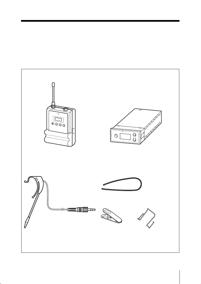
Configuration of the Package
The UWP-X5 consists of a body-pack transmitter (UTX-B1), a diversity tuner module (URXM1) and their accessories. By installing the tuner module into the tuner base unit or the
powered mixer, the system construction to meet the desired purpose of use and required
system scale becomes possible.
Body-pack transmitter (UTX-B1) (1)
Supplied accessories
Head-set type microphone (1)
Diversity tuner module (URX-M1) (1)
Headband (1)
Clip (1)
Belt clip (1)
Operating Instructions (1)
Sony Wireless Microphone System Frequency List (1) ((2) for CE67 model only)
Warranty card (1) (for U62 and U66 models)
Configuration of the Package
11

Features
Precautions
The UWP-X5 Wireless Microphone
Package consists of a transmitter (bodypack transmitter (UTX-B1)), a receiver
(diversity tuner module (URX-M1)), and
the accessories. The UWP-X5 can be used
with the tuner base unit or the powered
mixer for AV presentations.
Note
The UWP-X5 is not compatible with
conventional WRT series transmitters,
WRR series tuners, or WRU series tuner
units.
The featured components of the package are
described below.
Body-pack transmitter (UTXB1)
This is a small and lightweight transmitter
with a crystal-controlled PLL (phase lock
loop) synthesized system and a BMP-type
microphone input connector. The RF power
output can be set at 30 mW or at 5 mW.
Diversity tuner module (URXM1)
This tuner module can be incorporated into
the MB-X6 Tuner Base Unit or SRP-X500P
Powered Mixer.
Head-set type microphone
(supplied)
This electret condenser microphone is
equipped with the omni-directional capsule
to obtain sound with clarity and quality, ear
clip to easily wear on either ear, and flexible
boom allowing you to finely adjust the
position and angle of the microphone.
• The UWP-X5 units must be used within
a temperature range of 0°C to 40°C (32°F
to 104°F).
• Operating the UWP-X5 units near
electrical equipment (motors,
transformers, or dimmers) may cause it to
be affected by electromagnetic induction.
Keep the UWP-X5 units as far from such
equipment as possible.
• The presence of the lighting equipment
may produce electrical interference over
the entire frequency range. Position the
UWP-X5 units so that interference is
minimized.
• To avoid degradation of the signal tonoise ratio, do not use the UWP-X5 units
in noisy places or in locations subject to
vibration, such as the following:
- near electrical equipment, such as
motors, transformers or dimmers
- near air conditioning equipment or
places subject to direct air flow from
an air conditioner
- near public address loudspeakers
- where adjacent equipment might
knock against the tuner
Keep the UWP-X5 units as far from such
equipment as possible or use buffering
material.
• Clean the surface and the connectors of
the UWP-X5 units with a dry, soft cloth.
Never use thinner, benzene, alcohol or
any other chemicals, since these may mar
the finish.
Features / Precautions
12
To prevent electromagnetic
interference from portable
communication devices
The use of portable telephones and
other communication devices near
the UWP-X5 products may result in
malfunction and interference with
audio signals. It is recommended that
portable communication devices near
the UWP-X5 products be turned off.
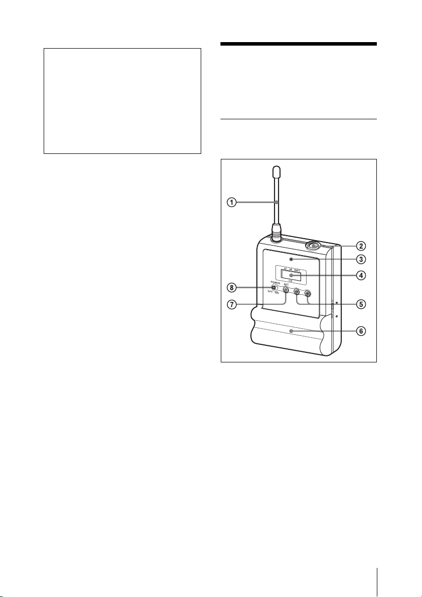
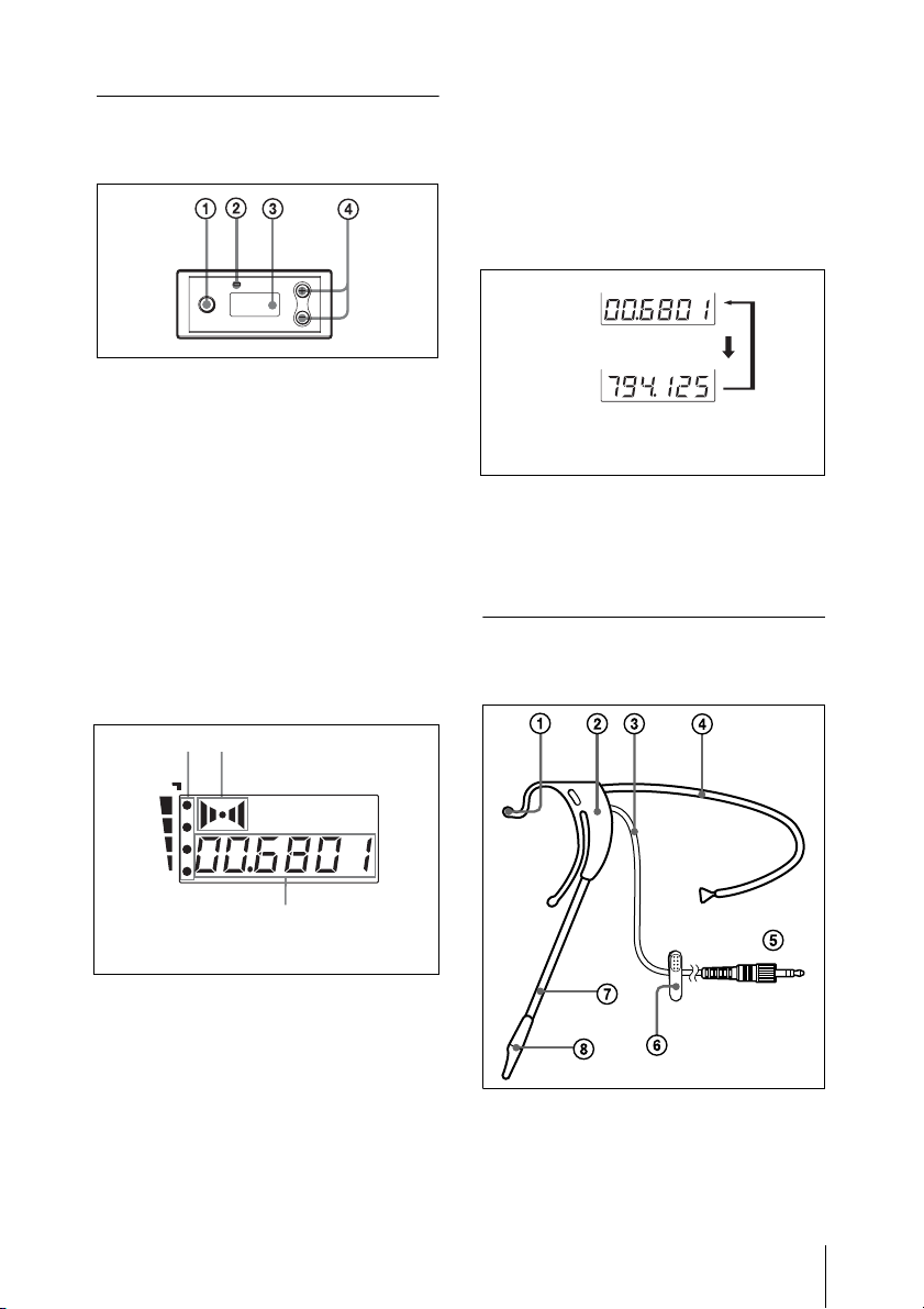
Parts Identification
Body-pack transmitter (UTX-B1)
a Antenna
b Audio input connector
Connect the supplied head-set type
microphone here.
c Power indicator
Lights up red when the transmitter is tuned
on.
Parts Identification
13
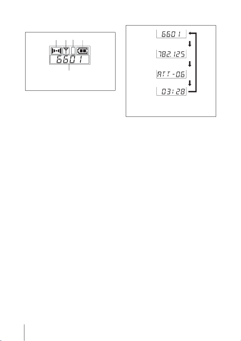
d Display section
E
C
D
B
A
AF RFCHBATT
The channel indication (E) for U66
model is shown.
H
L
A AF (audio frequency) indication
Appears whenever the input audio signal is
stronger than the reference level.
Transmission
channel
Transmission
frequency
Attenuation
level of the
input signal
Accumulated
battery use
time
The channel/frequency indications for
U66 model are shown.
Press
the
SET
button.
B RF (radio frequency) indication
Appears during signal transmission from
the antenna.
C RF (radio frequency) level
indication
Shows the RF output level setting.
For details, see “Setting the RF output power level
(UTX-B1 only)” on page 26.
D BATT (battery) indication
Shows the battery condition.
For details, see “Battery indication” on page 17.
E CH (channel) indication
Shows the transmission channel. Each time
you press the SET button in transmission
mode, the channel indication changes as
follows.
For details, see “Settings” on page 22.
e + (+ selection) / – (– selection/reset)
buttons
Press these buttons to set the transmission
channel, frequency, or attenuation level of
the input signal.
The “–” button resets the accumulated
battery use time to “00:00”.
f Battery compartment
Accommodates two LR6 (size AA) alkaline
batteries.
For details on how to insert the batteries, see
“Power Supply” on page 16.
g SET button
Press to change and enter display
parameters.
For details, see “Settings” on page 22.
h POWER switch
Turns the power of the transmitter ON or
OFF.
Parts Identification
14
Diversity tuner module
C
(URX-M1)
a SET button
Press to change display parameters.
For details, see “Settings” on page 22.
C GP (group)/CH (channel) indication
Shows the reception channel group and
channel number. Each time you press the
SET button, the channel indication changes
as follows.
For details, see“Settings” on page 22.
Reception
channel group
and number
Reception
frequency
The channel/frequency indications for
U66 model are shown.
Press
the
SET
button.
b RF (radio frequency) indicator
The color indicates the strength of the
RF input signal.
On in green: RF input is 25 dBµ
or more.
Off: RF input is less than 25 dBµ
* 0 dBµ = 1 µV
EMF
*
*
.
c Display section
A
B
RF
AF
CH
The channel indication (C) for U66
model is shown.
A RF (radio frequency) indications
The number of dots indicates the RF input
level.
B AF (audio frequency) indication
Appears whenever the output audio signal
is stronger than the reference level.
d + (+ selection) / – (– selection/reset)
buttons
Press these buttons to set the reception
channel and frequency.
Head-set type microphone (supplied)
Parts Identification
15
a Ear clip
b Case
c Microphone cable
d Headband (supplied)
e Connector (mini phono plug with a
lock mechanism)
f Clip (supplied)
g Boom
h Capsule case
Power Supply
This section explains the power supply for
each component.
Diversity tuner module (URXM1)
When incorporated into another component
(e.g., MB-X6, SRP-X500P, etc.), the tuner
module draws its power from that
component.
For details on the power s upply to the diversity tuner
module, refer to the operating instructions of the
component in which the diversity tuner module is
installed.
Body-pack transmitter (UTXB1)
The body-pack transmitter can be powered
by two LR6 (size AA) alkaline batteries for
about six hours of continuous operation (at
25 ºC (77ºF)). Details on inserting the
batteries and the battery condition
indication are given below:
16
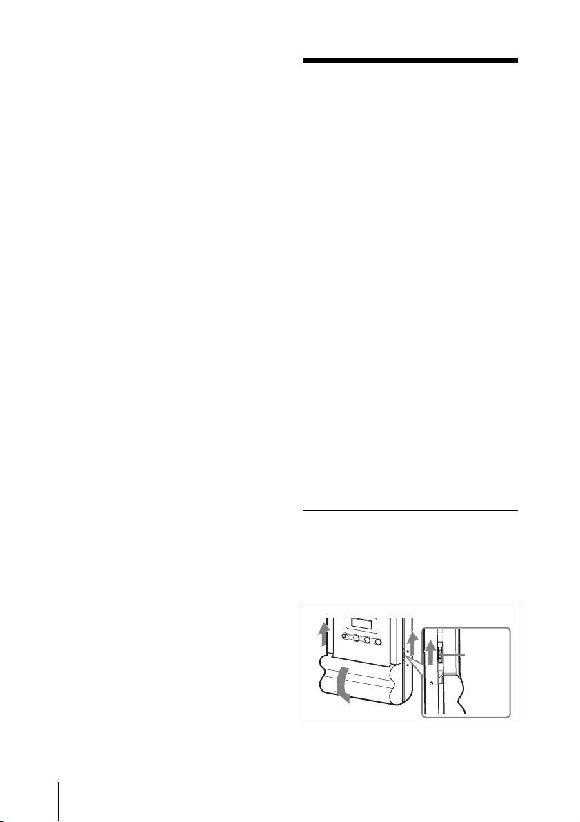
Inserting the batteries
1 Slide the latches on both sides of the
transmitter at the same time and open
the battery compartment.
Latch
Power Supply
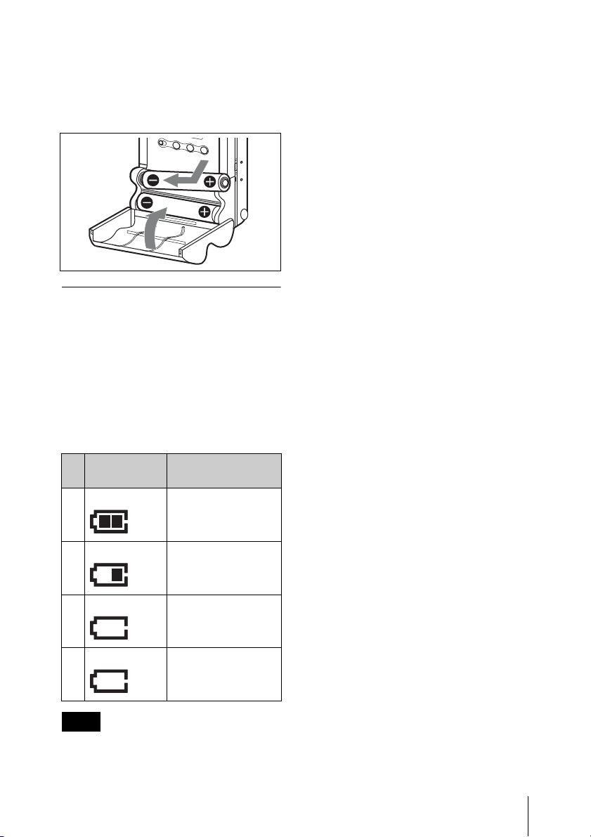
2 Align two new LR6 (size AA) alkaline
batteries with the polarity markings
and insert them into the battery
compartment, and then close the cover.
Battery indication
When you turn the power on, the battery
condition is shown by the BATT indication
in the display section.
When the indication in column 4 starts to
flash, replace the batteries with new ones.
Be sure to check the expiration date printed
on the new batteries before using them.
installed. If you plan to use the component
for a long period, it is recommended that
you replace the batteries with brand new
ones.
Notes on battery
Batteries may leak or explode if mistreated.
Be sure to follow these instructions.
• Be sure to install the batteries with the
correct polarity.
• Always replace the two batteries
together.
• Do not use different types of batteries or
old and new one together.
• The batteries are not rechargeable.
• When not using the component for a long
period of time, remove the batteries to
avoid leakage. If the batteries do leak,
clean all leakage from the battery
compartment and the component.
Leakage left in the compartment and the
component may cause poor battery
contact. If there seems to be poor battery
contact, consult your Sony dealer.
BATT
indication
1Lights
2Lights
3Lights
4 Flashes Almost drained
Battery status
Good
Less than 50%
charged
Less than 20%
charged
Note
The indicated battery condition may not be
correct if the batteries were not new when
Power Supply
17
Attachment and
To wear the head-set type
microphone
Installation
Procedures
This section describes the procedures for
attaching the supplied accessories to the
body-pack transmitter (UTX-B1) and the
installation of the diversity tuner module
(URX-M1) into the MB-X6 Tuner Base
Unit or SRP-X500P Powered Mixer.
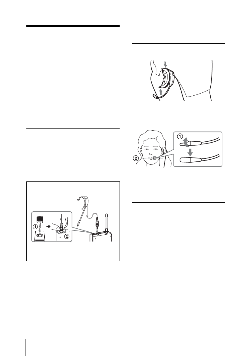
Attaching the supplied
accessories to the bodypack transmitter (UTX-B1)
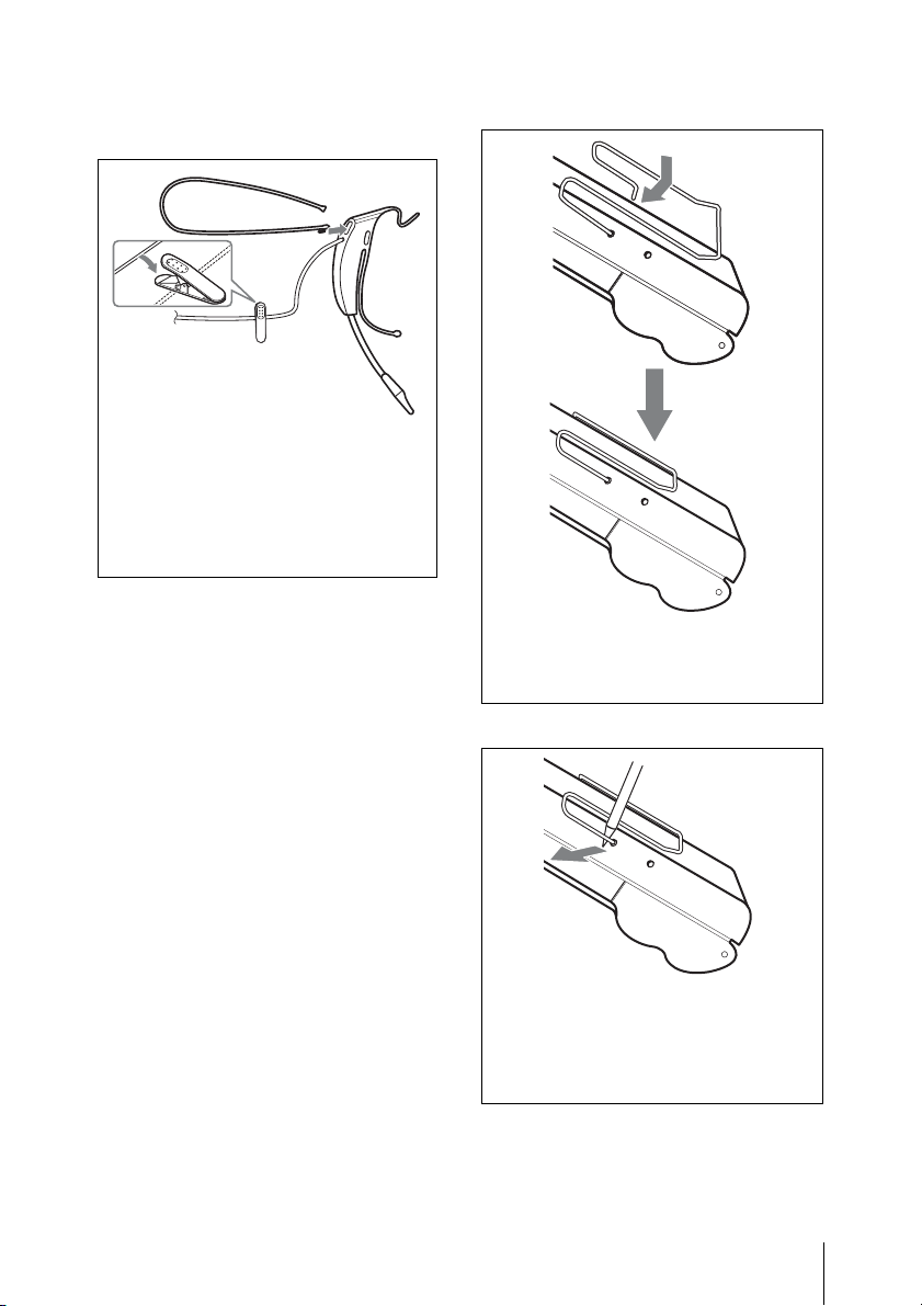
To attach the head-set type
microphone
Head-set type microphone
(supplied)
The head-set type microphone
can be worn on either ear.
Hook the upper part of the ear clip on an
ear, then press the ear clip gently onto the
ear to settle it in place.
To obtain proper sound quality, twist the
boom so that the threads on the capsule
case face toward the mouth (1), then
pull the capsule case on the extensive
line from the mouth (2).
Insert the plug (1), then turn and
lock the connector cover (2).
Attachment and Installation Procedures
18
To attach the headband and
clip
The headband can be
attached on either side.
To wear the microphone more securely,
attach the supplied headband (1) before
wearing the microphone.
To prevent the microphone from falling off,
attach the supplied clip (2) to the
microphone cable, then clip the
microphone cable to the clothing.
To attach the belt clip
Insert one end of the belt clip into one of
two holes on either side of the transmitter,
and then insert the other end into the hole
on the other side.
To remove the belt clip
Insert a pointed object such as a ballpoint
pen between the belt clip and the
transmitter to make some space between
them, and then remove the end of the belt
clip from the hole on the side of the
transmitter.
Attachment and Installation Procedures
19
Installing a diversity tuner module (URX-M1)
Notes
• Before installing the diversity tuner
module (URX-M1), make sure the unit
into which the tuner module will be
installed is turned off. Do not install or
uninstall the tuner module while the unit
into which the tuner module will be
installed is turned on, as this may damage
the connector or cause noise.
• The buttons and display on the front
panel of the tuner module may be
damaged if they are gripped too strongly.
Always hold the tuner module by the
side.
• Do not put your fingers on the connectors
on the rear panel of the tuner module or
into the slot on the unit into which the
tuner module will be installed.
• Keep the tuner module away from static
electricity.
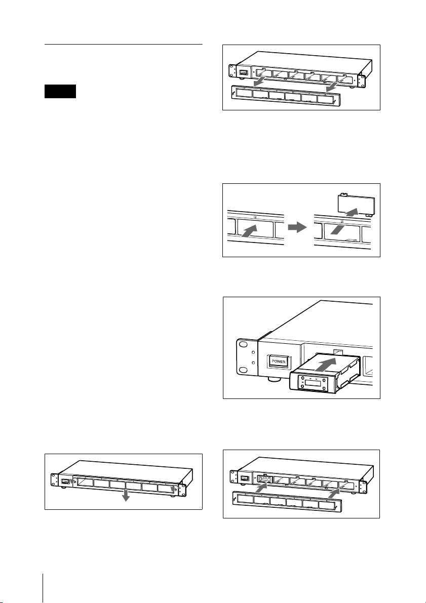
To install a diversity tuner
module (URX-M1) into an MBX6 Tuner Base Unit
The MB-X6 Tuner Base Unit can
accommodate up to 6 diversity tuner
modules (URX-M1).
3 When installing the tuner unit into the
tuner slot other than slot 1, push the
corresponding blank panel from the
front side of the front cover to remove
it.
4 Insert the tuner unit into the slot until
you hear a click.
1 Loosen the screws at both sides of the
front cover, then slide the front cover
downward.
2 Hold the screws by the head and pull
forward to remove the front cover.
Attachment and Installation Procedures
20
5 Match the six latches with the six holes
on the front panel, then replace the
front cover.
6 Tighten the screws on the front cover
to secure it to the front panel of the
MB-X6.
To remove a diversity tuner
module
After removing the front cover, hold the
tuner unit by the top and bottom, then pull it
out of the slot.
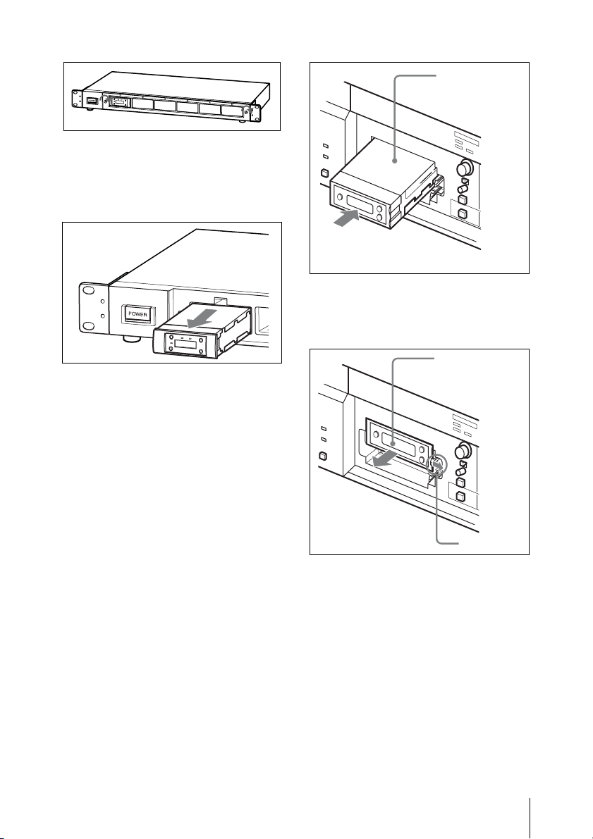
To install a diversity tuner
module (URX-M1) into an
SRP-X500P Powered Mixer
The SRP-X500P Powered Mixer can
accommodate up to two diversity tuner
modules (URX-M1).
Tuner module
To remove the diversity tuner
module
Pull the latch securing the tuner module to
the side and pull out the tuner module.
Tuner module
Remove the tuner slot cover from the SRPX500P and inspect the top and bottom sides
of the diversity tuner module. Then, insert it
into the slot.
Latch
Attachment and Installation Procedures
21
Settings
The right four digits start to flash to
allow the selection of the channel
number.
3) Select the channel number by
pressing the + or – button.
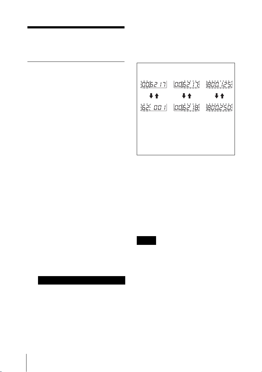
Setting the transmission channel (UTX-B1 only)
Refer to the supplied leaflet “Sony Wireless
Microphone System Frequency List” for details on
the selectable channel groups and channels.
1 Turn on the transmitter while pressing
down the SET button.
Keep pressing the SET button until the
display section parameters that were
displayed when the unit was last turned
off start to flash.
2 Press the SET button repeatedly until
the channel number (or frequency)
indication appears.
3 Press the + or – button to select the
channel number (or frequency).
Pressing the + button cycles the
indication in the order shown in the
tables in the supplied leaflet “Sony
Wireless Microphone System
Frequency List.”
Pressing the – button cycles the
indications in the opposite direction.
Hold down the + or – button to change
the channel number (or frequency)
faster.
Notes on the European model
Select the group number before
selecting the channel number as
follows.
1) While the left two digits are
flashing, select the group number
by pressing the + or – button.
2) While the desired group number
appears, press the SET button.
Group
selection
V: + button
Group, channel, and frequency
selection examples for CE62 model
are shown.
Channel
selection
Frequency
selection
v: – button
4 When the desired channel number (or
frequency) appears, set the POWER
switch to OFF to complete the setting,
or press the SET button to set other
items.
The results are stored in memory. The
stored channel number (or frequency)
will appear in the display section the
next time you turn on the transmitter
by setting the POWER switch to ON.
Notes
• When you are setting the transmission
channel, the transmitter cannot be used to
transmit signals.
• Do not remove the batteries while setting
the transmission channel. If they are
inadvertently removed, re-insert them
immediately and redo the procedure
“Setting the transmission channel (UTXB1 only)” from step 1.
• Make sure that the selected channel is the
same on the transmitter and tuner being
used in the same system.
• If you turn off the transmitter and then
immediately turn it on right after setting
22
Settings
the transmission channel, the unit may
not operate normally. Wait a few seconds
before turning it on again.
Setting the reception channel (URX-M1 only)
Refer to the supplied leaflet “Sony Wireless
Microphone System Frequency List” for details on
the selectable channel groups and channels.
1 Press down the SET button for more
than one second.
Keep pressing the SET button until the
display section parameters start to
flash.
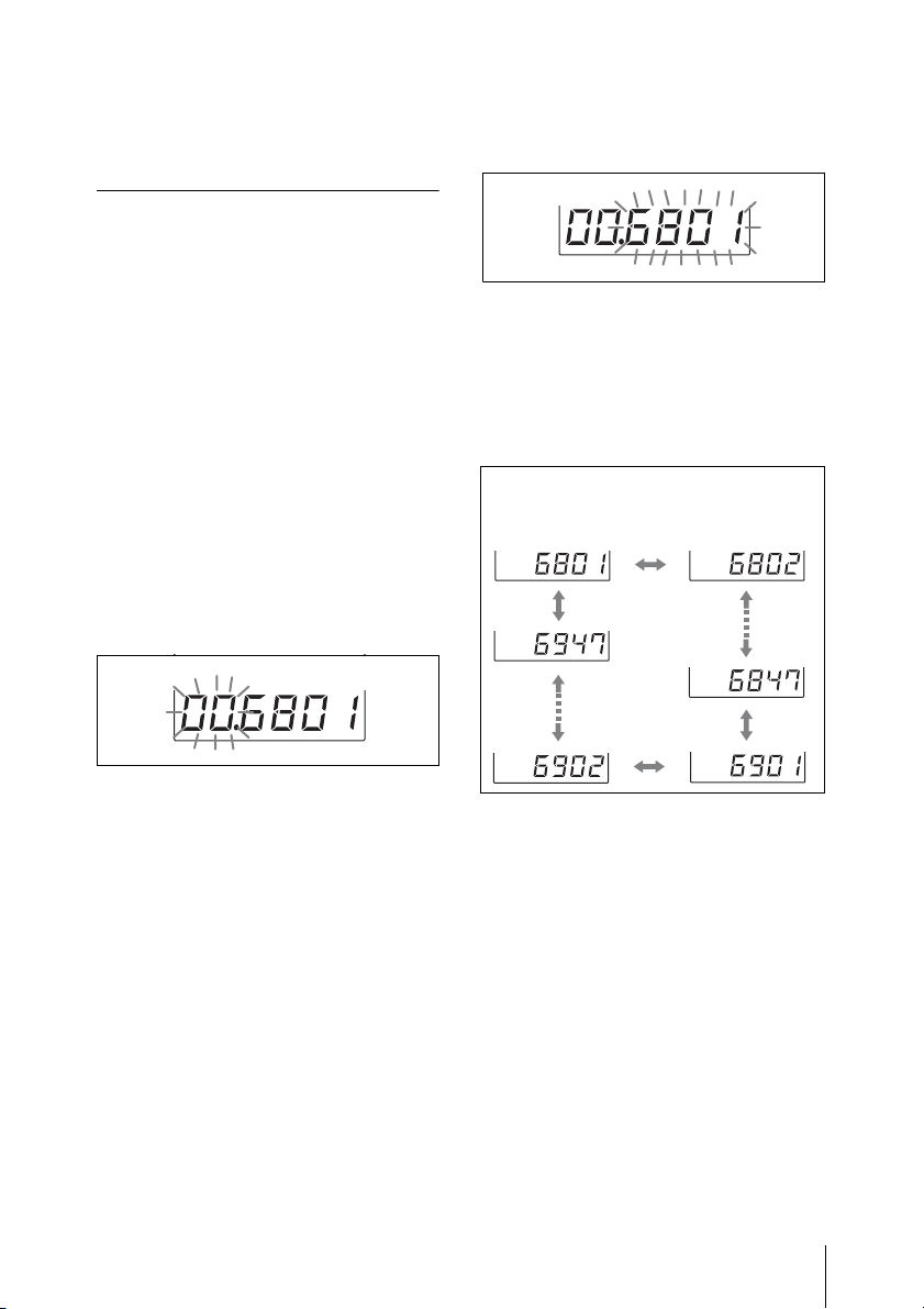
2 Press the SET button repeatedly until
the channel group and the channel
number indications appear.
The channel group indication starts to
flash.
The right four digits start to flash to
allow the selection of the channel
number.
5 Press the + or – button to select the
channel number.
The channel indication changes in the
order shown in the tables in the
supplied leaflet “Sony Wireless
Microphone System Frequency List.”
Example: When the channel group 00 is
selected
3 Press the + or – button to select the
channel group.
Pressing the + button cycles the
indication in the order shown in the
tables in the supplied leaflet “Sony
Wireless Microphone System
Frequency List.”
Pressing the – button cycles the
indications in the opposite direction.
Hold down the + or – button to change
the channel group faster.
4 When the desired channel group
number appears, press the SET button.
The selected group is entered.
6 When the desired channel number
appears, leave the tuner for about 10
seconds until the selected channel
number stops flashing and the
selection is stored in memory.
To select the channel by
frequency indication
1 Press the SET button for more than one
second.
Keep pressing the SET button until the
display section parameters start to
flash.
Settings
23
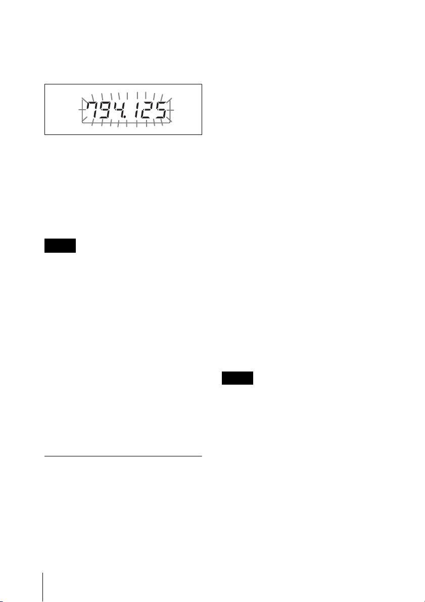
2 Press the SET button repeatedly until
the frequency indication appears and
starts flashing.
3 Press the + or – button to select the
frequency.
4 When the desired frequency appears,
leave the tuner for about 10 seconds
until the selected channel frequency
stops flashing and the selection is
stored in memory.
Notes
• When you are setting the reception
channel, the tuner can be used to receive
signals.
• Do not remove the batteries while setting
the reception channel. If they are
inadvertently removed, re-insert them
immediately and redo the procedure
“Setting the reception channel (URX-M1
only)” from step 1.
• Make sure that the selected channel is the
same on the transmitter and tuner being
used in the same system.
• If you turn off the tuner and then
immediately turn it on right after setting
the reception channel, the unit may not
operate normally. Wait a few seconds
before turning it on again.
Detecting and selecting the available channels automatically (URX-M1 only)
operation, select the channel group on the
tuner module installed into the slot 1 of
the MB-X6, then all the tuner modules
installed into the MB-X6 can be set to
different channels within the selected
channel group.
1 Turn off all the microphones and
transmitters.
2 Select the channel group on the tuner
module installed into the slot 1 of the
MB-X6.
3 After confirming that the channel
group indication has stopped flashing
(about 10 seconds after you have
selected the channel group), keep
pressing the + button on the tuner
module installed into the slot 1 of the
MB-X6.
All the tuner modules installed into the
MB-X6 are set to the available
channels within the selected channel
group.
After the automatic detection and
selection of available channels finish,
you can change the group and channel
on each tuner module manually.
Notes
• Do the automatic detection and selection
of available channels with the channel
group other than channel group 00.
• When there are unavailable channels due
to extraneous radio wave and the channel
could not be selected on some tuner
modules, “NO CH” appears on the
display of those tuner modules. If this
happens, select the channel group with no
interference from extraneous radio wave,
and repeat the procedure above.
When multiple diversity tuner modules
(URX-M1) are installed into the MB-X6 to
perform simultaneous multiple-channel
Settings
24
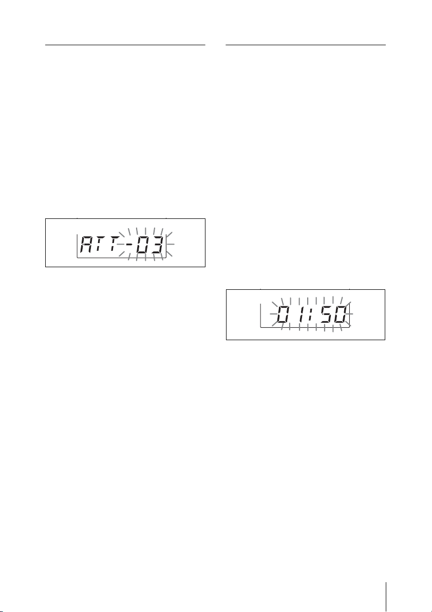
Setting the attenuation level of the audio input (UTX-B1 only)
Resetting the accumulated battery use time indication (UTX-B1 only)
The attenuation level can be set during
signal transmission.
1 Do the following while there is
no signal transmission.
Turn on the transmitter while pressing
down the SET button, and press the
SET button repeatedly until the
attenuation level indication appears in
the display section.
Do the following while there is
signal transmission.
Press the SET button repeatedly until
the attenuation level indication appears
in the display section.
2 Press the + or – button to select the
attenuation level.
The selectable range is from 0 dB to 21
dB in steps of 3 dB (the factory setting
is 0 dB).
3 Do the following while there
is no signal transmission.
Set the POWER switch to OFF to
complete the setting, or press the SET
button to set other items.
The results are stored in memory.
The change becomes effective the next
time you turn on the transmitter by
setting the POWER switch to ON.
The accumulated battery use time is the
total time (in hours and minutes) that the
batteries have been used. It is recorded
whenever the transmitter is on.
Reset the indication to “00:00” whenever
you replace the batteries.
1 Turn on the unit while pressing down
the SET button.
Keep pressing the SET button until the
display section parameters start to
flash.
2 Press the SET button repeatedly until
the accumulated time indication
appears in the display section.
3 Press the – button.
The time indication resets to “00:00.”
While “00:00” is still displayed, you
can return to previous value by
pressing the + button.
4 Set the POWER switch to OFF to
complete the setting, or press the SET
button to set other items.
The results are stored in memory.
The change becomes effective the next
time you turn on the unit by setting the
POWER switch to ON.
Settings
25
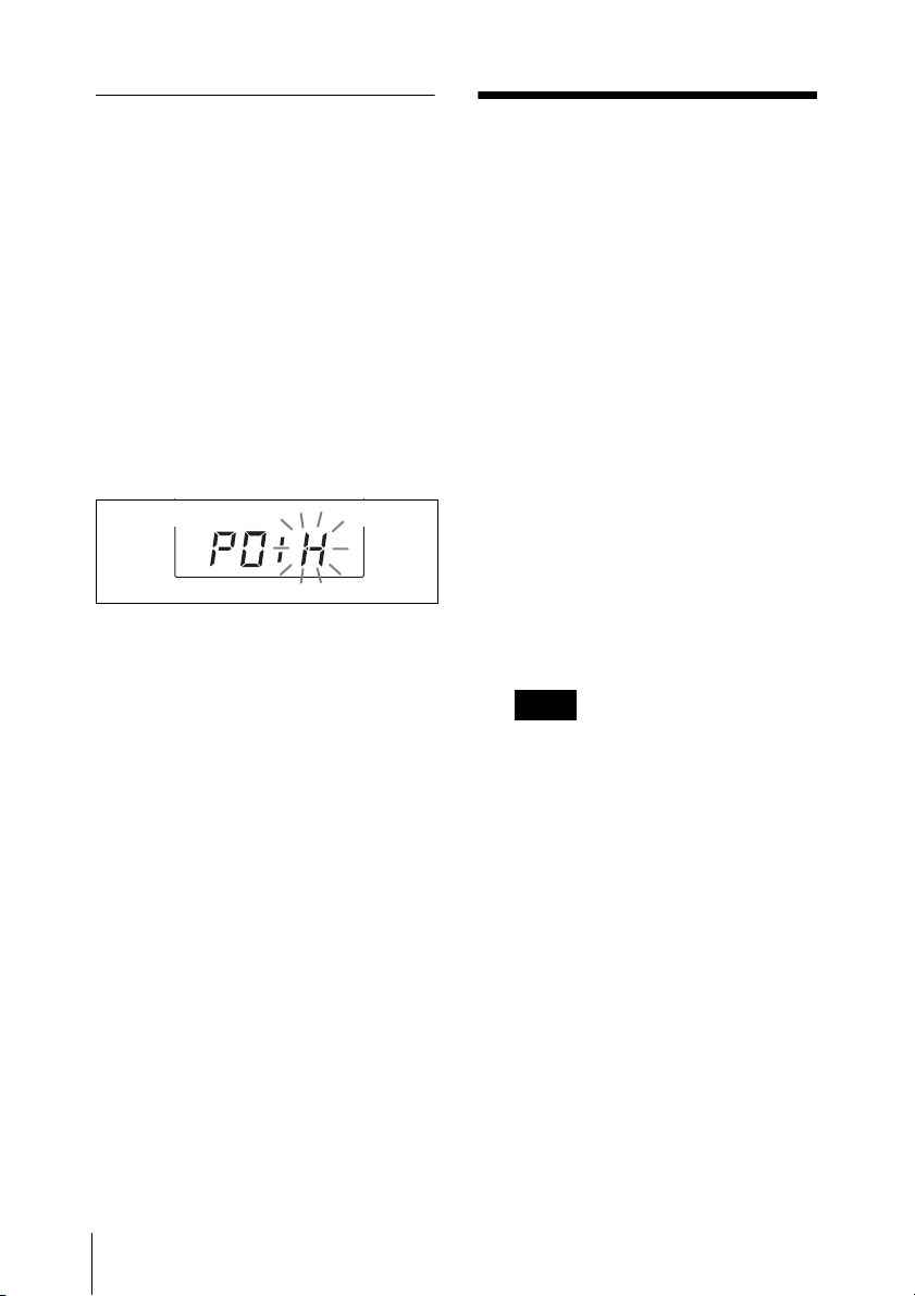
Setting the RF output power level (UTX-B1 only)
You can select the RF output power level
from “H” (30 mW) or “L” (5 mW) in setting
Set the RF output level to L (5
mode
mW) for simultaneous operation of
multiple channels, and set it to H (30
mW) for long-distance operation.
Operation
The procedure below is the same for the
UTX-B1 and URX-M1.
1 Make all necessary connections on the
tuner.
1 Turn on the transmitter while pressing
down the SET button.
2 Press the SET button repeatedly until
the RF output level indication appears
in the display section.
3 Press the + button to select “H” (30
mW), or press the – button to select
“L” (5 mW).
4 Set the POWER switch to OFF to
complete the setting, or press the SET
button to set other items.
The results are stored in memory.
The change becomes effective the next
time you turn on the transmitter by
setting the POWER switch to ON.
For examples of UWP-X5 component
connections, see “System Configuration” on
page 28.
2 Set the transmission channel on the
transmitter, and then turn off the unit.
For details on setting the transmission
channel, see “Sett ing the transmission channel
(UTX-B1 only)” on page 22.
3 Turn on the tuner.
The parameters that were in the display
section when the tuner was last turned
off appear again.
Note
Before turning on the tuner, turn down
the volume of the equipment
connected to the tuner.
Otherwise, noise will be produced
when the tuner is turned on.
4 Set the reception channel on the tuner.
For details on setting the reception channel,
see “Setting the reception channel (URX-M1
only)” on page 23.
26
5 Turn on the transmitter.
If noise is heard
Depending on the environment where the
UWP-X5 components are installed,
external noise or radio waves may disrupt
transmission on certain channels.
Operation

When selecting a channel under these
circumstances, turn off the transmitter.
Then, on the tuner, select a channel for
which the RF indications do not appear in
the display section or for which the RF
indicator does not light up (i.e., a channel
free from noise or radio wave interference).
Set the same channel on the transmitter.
Note
To prevent interference or noise, please
take the following precautions.
• Do not use two or more transmitters with
the same wireless channels.
• When operating two or more UWP-X5’s
simultaneously, set each package to a
different channel within the same
channel group.
• Keep the reception antenna and the
transmitter separated more than 3 meters
(9 feet 11 inches).
• When operating two or more UWP-X5’s
simultaneously with the same channel
group, make sure that they are at least
100 meters (330 feet) apart, but within
clear sight of each other. (The actual
distance may differ depending on the
circumstances.)
Operation
27
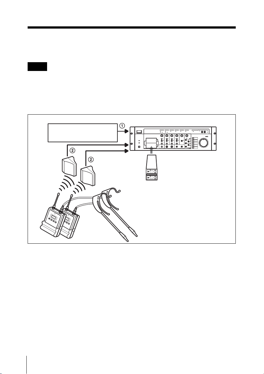
System Configuration
Note
Production of the peripheral and relating devices may have been discontinued. Upon selecting
the devices to be used with this product, consult your nearest Sony representative or the dealer
from whom you purchased the product.
Sample configurations for AV presentations
SRP-X500P Powered Mixer
To DVD player, PC, or
VTR, etc.
Diversity tuner
AN-820 UHF
antenna
module (URX-M1)
System Configuration
28
Body-pack
transmitter
(UTX-B1)
1 BNC cable
2 XLR cable or pin cable
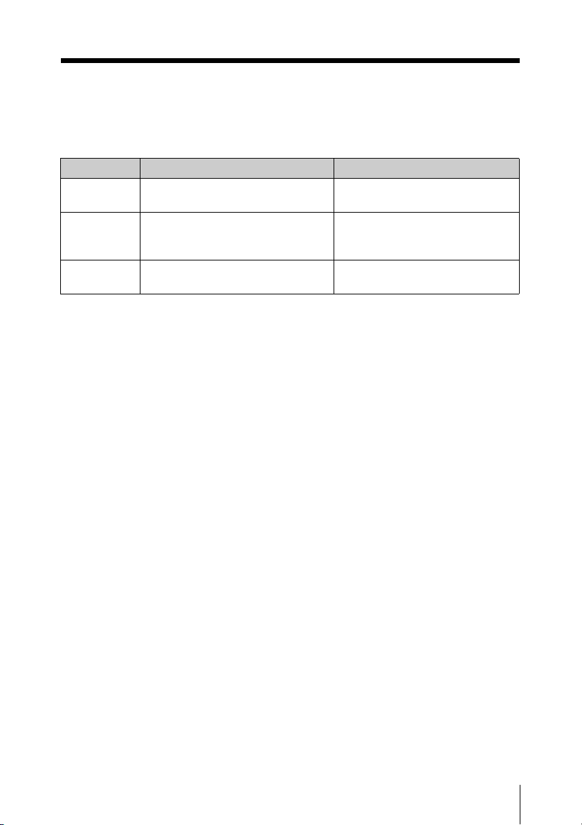
Error Messages
When a problem occurs, one of the following error messages may appear on the display.
Messages Meanings Remedy
Err 01 An error has occurred in the backup
memory data.
Err 02 The PLL synthesized circuit is
abnormal.
Err 03* The battery voltage exceeds the
allowable limit.
* Body-pack transmitter (UTX-B1) only
Contact your Sony dealer.
Restart the unit. If the message
appears again, contact your Sony
dealer.
Use the specified battery.
Error Messages
29
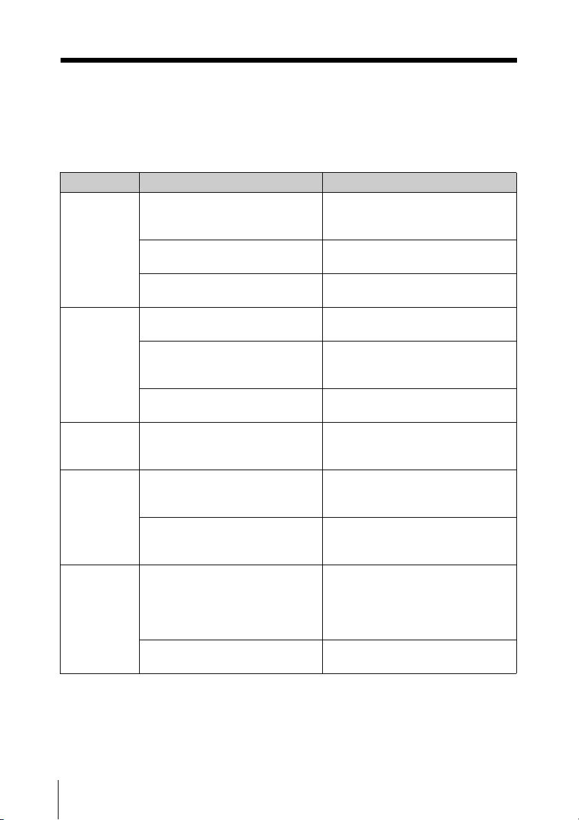
Troubleshooting
If you have any problem using the UWP-X5, use the following checklist.
Should any problem persist, consult your Sony dealer.
Symptom Meanings Remedy
The unit does
not turn on.*
The batteries
become
drained
quickly*.
The channel
cannot be
changed.
There is no
sound.
The sound is
weak.
The polarity orientation of the
batteries in the battery
compartment is incorrect.
The batteries are exhausted. Replace the batteries with new
The battery terminals in the
transmitter are dirty.
The batteries are exhausted. Replace the batteries with new
Manganese batteries are being
used.
The UWP-X5 is being used under
cold conditions.
An attempt was made to change
the channel by pressing the SET
button only.
The channel setting on the
transmitter is different from that
on the tuner.
The RF indications (RF indicator)
on the tuner do not appear at all
(or does not turn on).
The attenuation level on the
transmitter is too high.
The volume on the amplifier or
mixer is low.
Insert the batteries with the correct
polarity orientation.
ones.
Clean the + and – terminals with a
cotton swab.
ones.
Use alkaline batteries. The battery
life of a manganese battery is less
than half that of an alkaline battery.
The batteries drain quickly under
cold conditions.
Restart the unit while holding down
the SET button. Then change the
channel with the + and – buttons.
Use the same channel setting on
both the transmitter and tuner.
Confirm that the transmitter is
turned on.
The output level of the transmitter is
low. Press the + button on the
transmitter in attenuation level
setting mode to decrease the
attenuation level.
Adjust the volume.
30
Troubleshooting

Symptom Meanings Remedy
There is
distortion in
the sound.
There is
sound
interruption
or noise.
The attenuation level of the
transmitter is too low.
The transmitter and the tuner are
set to different channels.
The RF indications on the tuner
appear (the RF indicator lights
up) even when the transmitter is
off.
The transmitter and the tuner are
set to different channels.
Two or more transmitters are set
to the same channel.
The transmitters are not set to the
channels within the
same channel group.
The input level of the tuner is
extremely high. Press the – button
on the transmitter in attenuation
level setting mode to raise the
attenuation level.
Set the transmitter to the same
channel.
Jamming radio waves are being
received. Determine which
channels are usable (i.e., channels
for which the RF indications on the
tuner do not appear (or for which
the RF indicator on the tuner does
not light up)) and set the tuner and
transmitter to the same usable
channel. When two or more
transmitters are used
simultaneously, use another
channel group that is unaffected by
jamming radio waves.
Set the transmitter to the same
channel as the tuner.
Set each transmitter to a different
channel.
The channel plan which the UWPX5 components use is set so that
no signal interference occurs when
2 or more transmitters are used
simultaneously. Set each
transmitter to a different channel
within the same channel group.
* Body-pack transmitter (UTX-B1) only
Troubleshooting
31

Specifications
Transmitter (UTX-B1)
Oscillator type
Crystal-controlled PLL synthesizer
Carrier frequencies
Model available in USA: 758 to
806 MHz
Model available in Europe: 798 to
862 MHz
Model available in Australia: 792
to 806 MHz
Operating frequency band
Model available in USA and
Europe: 24 MHz BW
Model available in Australia: 14
MHz BW
Pre-emphasis
50 µs
Frequency characteristics
50 Hz to 18 kHz
Signal-to-noise ratio
60 dB or more
Tone signal
32 kHz
Attenuation
0 to 21 dB, in 3-dB steps
Display
Channel, frequency, audio level,
RF level, accumulated battery
use time
Power requirements
3.0 V DC (two LR6/AA size
alkaline batteries)
Battery life
Approx. 6 hours (measured with
two Sony LR6/AA size alkaline
batteries at 25°C (77°F), with
output power of 30 mW)
Antenna
λ wave length wire
1/4
Audio input connector
3.5-mm dia. mini jack
Audio input level
–60 dBV to –39 dBV
RF output level
30 mW/5 mW selectable
Reference deviation
±5 kHz
Distortion
1.0% or less
Indicator
Power on
Dimensions
63 × 100 × 27 mm (2 1/2 × 4 × 1 1/
inches) (w/h/d) (excluding the
8
antennas)
Mass Approx. 140 g (5 oz) including
batteries
Tuner (URX-M1)
Type of reception
Space diversity
Oscillator type
Crystal-controlled PLL synthesizer
Reception frequencies
32
Specifications

Model available in USA: 758 to
806 MHz
Model available in Europe: 798 to
862 MHz
Model available in Australia: 792
to 806 MHz
Operating frequency band
Model available in USA and
Europe: 24 MHz BW
Model available in Australia: 14
MHz BW
Signal-to-noise ratio
60 dB or more
De-emphasis
50 µs
Reference deviation
±5 kHz
Frequency characteristics
50 Hz to 18 kHz
Distortion
1.0% or less at 1 kHz modulation
Tone signal
32 kHz
Indicator
RF input level
Squelch level
25 dBµ
Display
Channel, frequency
Dimensions
1
57 × 26 × 121 mm (2
7
/8 inches) (w/h/d)
/4 × 11/16 × 4
Mass Approx. 150 g (5 oz)
Design and specifications are subject to
change without notice.
Note
Always verify that the unit is operating
properly before use. SONY WILL NOT
BE LIABLE FOR DAMAGES OF ANY
KIND INCLUDING, BUT NOT
LIMITED TO, COMPENSATION OR
REIMBURSEMENT ON ACCOUNT
OF THE LOSS OF PRESENT OR
PROSPECTIVE PROFITS DUE TO
FAILURE OF THIS UNIT, EITHER
DURING THE WARRANTY PERIOD
OR AFTER EXPIRATION OF THE
WARRANTY, OR FOR ANY OTHER
REASON WHATSOEVER.
Specifications
33

Français
Pour les émetteur
UTX-B1
Remarque à l’intention des
utilisateurs au Canada :
L’usage des appareils sans fil Sony est
réglementé par l’Industrie Canada comme
décrit dans leur Cahier des Normes
Radioélectriques CNR-123.
Une licence est normalement requise.
Le bureau de l’Industrie Canada doit être
contacté. Lorsque le fonctionnement de
l’appareil respecte les limites de la bande de
radiodiffusion, la licence est accordée sur la
base d’une non-interférence, nonprotection pour les signaux de
radiodiffusion.
L’utilisation de cet appareil est soumise aux
deux conditions suivantes: (1) cet appareil
ne peut causer d’interférences, et (2) cet
appareil doit accepter toutes les
interférences, y compris les interférences
capables de provoquer un fonctionnement
non souhaité de l’appareil.
L’expression <<IC:>> avant le numéro
d’homologation/enregistrement signifie
seulement que les spécifications techniques
de l’Industrie Canada ont été respectées.
Notification aux clients
européens
Sony Corporation déclare par ces présentes
que le UTX-B1 est conforme aux exigences
essentielles et aux dispositions applicables
de la Directive 1999/5/CE.
Pour les détails, accédez à l’URL suivante:
http://www.compliance.sony.de/
Remarque:
Dans certains pays, des bandes de
fréquences additionnelles pourront être
utilisées avec l’accord des autorités
nationales.
Note concernant les utilisateurs en
Suisse :
Une demande de concession de microphone
sans fil (fréquence classe 3) doit être
présentée au Bakom avant d’utiliser
l’appareil.
Remarque pour les clients au
Luxembourg:
Avant tout emploi de cet appareil, si
nécessaire conformément à la
réglementation en vigueur, les fréquences
requises doivent être assignées, avant
l’usage par le “ILT”.
Remarque concernant les utilisateurs en
Belgique :
L’emploi du UTX-B1 avec une puissance
de sortie RF 30 mW n’est pas autorisé. Bien
régler la puissance de sortie RF à 5 mW.
Royaume-Uni 854,125 - 862 MHz
Allemagne 790 - 814 MHz
Norvège 800 - 820 MHz
Luxembourg 800 - 830 MHz,
854,125 - 862 MHz
Belgique 854,125 - 862 MHz
Danemark 800,100 - 819,900 MHz
France 798 - 830 MHz
Italie 800 - 820 MHz
Suède 800 - 820 MHz
Suisse 800 - 820 MHz
Finlande 800,100 - 819,900 MHz
Islande 800 - 814 MHz
34
Pour les tuners
URX-M1
Remarque à l’intention des
utilisateurs au Canada:
L’usage des appareils sans fil Sony est
réglementé par l’Industrie Canada comme
décrit dans leur Cahier des Normes
Radioélectriques CNR-123.
Une licence est normalement requise.
Le bureau de l’Industrie Canada doit être
contacté. Lorsque le fonctionnement de
l’appareil respecte les limites de la bande de
radiodiffusion, la licence est accordée sur la

base d’une non-interférence, nonprotection pour les signaux de
radiodiffusion.
L’utilisation de cet appareil est soumise aux
deux conditions suivantes: (1) cet appareil
ne peut causer d’interférences, et (2) cet
appareil doit accepter toutes les
interférences, y compris les interférences
capables de provoquer un fonctionnement
non souhaité de l’appareil.
L’expression <<IC:>> avant le numéro
d’homologation/enregistrement signifie
seulement que les spécifications techniques
de l’Industrie Canada ont été respectées.
Notification aux clients
européens
Royaume-Uni 854,125 - 862 MHz
Allemagne 790 - 814 MHz
Norvège 800 - 820 MHz
Luxembourg 800 - 830 MHz,
854,125 - 862 MHz
Belgique 854,125 - 862 MHz
Danemark 800,100 - 819,900 MHz
France 798 - 830 MHz
Italie 800 - 820 MHz
Suède 800 - 820 MHz
Suisse 800 - 820 MHz
Finlande 800,100 - 819,900 MHz
Islande 800 - 814 MHz
Sony Corporation déclare par ces présentes
que le URX-M1 est conforme aux
exigences essentielles et aux dispositions
applicables de la Directive 1999/5/CE. Pour
les détails, accédez à l’URL suivante:
http://www.compliance.sony.de/
FR
35

Table des matières
Configuration de la boîte d’emballage................................ 37
Caractéristiques ....................................................................38
Précautions ............................................................................38
Identification des parties ......................................................39
Emetteur portatif (UTX-B1) ...........................................39
Module de tuner en diversité (URX-M1) .......................41
Microphone casque (fourni) ...........................................41
Alimentation ..........................................................................42
Insertion des piles ...........................................................42
Indication de l’état des piles ...........................................43
Procédures de fixation et d’installation ..............................44
Fixation des accessoires fournis à l’émetteur portatif
(UTX-B1) .......................................................................44
Installation d’un module de tuner (URX-M1) ................46
Réglages .................................................................................48
Réglage du canal de transmission (UTX-B1 seulement) 48
Réglage du canal de réception (URX-M1 seulement) ....49
Détection et sélection automatiques des canaux disponibles
(URX-M1 seulement) .....................................................50
Réglage du niveau d’atténuation de l’entrée audio
(UTX-B1 seulement) ......................................................51
Remise à zéro de l’indication de temps d’utilisation cumulé
(UTX-B1 seulement) ......................................................51
Réglage du niveau de sortie RF (UTX-B1 seulement) ...52
Fonctionnement .....................................................................53
Configurations de système ................................................... 54
Messages d’erreur................................................................. 55
Dépannage ............................................................................. 56
Spécifications .........................................................................58
36

Configuration de la boîte d’emballage
Le UWP-X5 comprend un émetteur portatif (UTX-B1), un module de tuner en diversité
(URX-M1) et leurs accessoires. L’installation du module de tuner dans l’unité de base de
tuner ou le mixeur/ampli permet de construire un système pour satisfaire l’objectif
d’utilisation souhaité et la taille de système requise.
Emetteur portatif (UTX-B1) (1)
Accessoires fournis
Microphone casque (1)
Module de tuner en diversité (URX-M1) (1)
Serre-tête (1)
Pince (1)
Pince pour ceinture (1)
Mode d’emploi (1)
Liste des fréquences du système de microphone sans fil Sony (1) ((2) pour le modèle
CE67 seulement)
Carte de garantie (1) (pour les modèles U62 et U66)
Configuration de la boîte d’emballage
37

Caractéristiques
Précautions
L’ensemble de microphone sans fil UWPX5 comprend un émetteur (émetteur
portatif (UTX-B1)), un récepteur (module
de tuner en diversité (URX-M1)) et les
accessoires. Le UWP-X5 peut être utilisé
avec l’unité de base de tuner ou le mixeur/
ampli pour les présentations audiovisuelles.
Remarque
Le UWP-X5 n’est pas compatible avec les
émetteurs de série WRT conventionnels, les
tuners de série WRR ou les tuners de série
WRU.
Les composants contenus dans la boîte
d’emballage sont décrits ci-dessous.
Emetteur portatif (UTX-B1)
C’est un petit émetteur léger à système
synthétisé à boucle à verrouillage de phase
(PLL) piloté par quartz et à connecteur
d’entrée de microphone de type BMP. La
puissance de sortie RF est réglable à 30 mW
ou 5 mW.
Module de tuner en diversité
(URX-M1)
Ce module de tuner peut être incorporé dans
une unité de base de tuner MB-X6 ou un
mixeur/ampli SRP-X500P.
Microphone casque (fourni)
Ce microphone à électret est équipé d’une
capsule omnidirectionnelle permettant un
son clair et de qualité, d’une pince d’oreille
pour le porter facilement sur l’une ou
l’autre oreille, et d’une perche flexible vous
permettant de régler précisément la position
et l’angle du microphone.
• Les unités UWP-X5 doivent être utilisées
sur une gamme de températures de 0°C à
40°C (32°F à 104°F).
• Les unités UWP-X5 peuvent être
affectées par l’induction
électromagnétique en cas de
fonctionnement près d’un appareil
électrique (moteur, transformateur ou
gradateur). Maintenez-les aussi loin que
possible de tels appareils.
• La présence d’appareils d’éclairage peut
provoquer des interférences électriques
sur toute la gamme de fréquences. Placez
les unités UWP-X5 de manière à
minimiser cette interférence.
• Pour éviter la dégradation du rapport
signal/bruit, n’utilisez pas les unités
UWP-X5 à un emplacement bruyant ou
soumis à des vibrations comme les
suivants :
- près d’un appareil électrique, tel que
moteur, transformateur ou gradateur
- près d’un appareil de climatisation ou
d’endroits soumis au flux d’air direct
d’un climatiseur
- près de haut-parleurs de diffusion
publique
- où un appareil adjacent peut heurter le
tuner
Maintenez les unités UWP-X5 aussi loin
que possible d’un tel appareil ou utilisez
un matériau de gainage.
• Nettoyez la surface et les connecteurs des
unités UWP-X5 avec un chiffon doux et
sec. N’utilisez jamais de diluant, de
benzène, d’alcool ou un autre produit
chimique, car ils pourraient altérer la
finition.
Caractéristiques / Précautions
38

Pour éviter les interférences
électromagnétiques de dispositifs
de communication portables
L’emploi de téléphones portables et
d’autres dispositifs de communication
près des produits UWP-X5 peut se
traduire par un mauvais
fonctionnement et une interférence
avec les signaux audio. Il est
recommandé de couper ces
dispositifs de communication
portables près des produits UWP-X5.
Identification des parties
Emetteur portatif (UTX-B1)
a Antenne
b Connecteur d’entrée audio
Raccordez-y le microphone casque fourni.
c Indicateur d’alimentation
S’allume en rouge à la mise sous tension de
l’émetteur.
Identification des parties
39

d Afficheur
E
C
D
B
A
AF RFCHBATT
L’indication de canal (E) pour le
modèle U66 est représentée.
H
L
A Indication AF (audiofréquence)
Apparaît quand le signal audio d’entrée est
plus fort que le niveau de référence.
B Indication RF (radiofréquence)
Apparaît pendant la transmission du signal
de l’antenne.
C Indication du niveau RF
(radiofréquence)
Indique le réglage du niveau de sortie RF.
Pour les détails, voir « Réglage du niveau de sortie
RF (UTX-B1 seulement) » à la page 52.
D Indication BATT (piles)
Indique l’état des piles.
Pour les détails, voir « Indication de l’état des
piles » à la page 43.
E Indication CH (canal)
Indique le canal de transmission. Chaque
fois que vous appuyez sur la touche SET en
mode de transmission, l’indication de canal
change comme suit.
Pour les détails, voir « Réglages » à la page 48.
Canal de
transmission
Fréquence de
transmission
Niveau
d’atténuation
du signal
d’entrée
Temps
d’utilisation
cumulé des
piles
Les indications de canal/fréquence pour
le modèle U66 sont représentées.
Appuyez
sur le
bouton
SET.
e Boutons + (sélection +)/ – (sélection –
/remise à zéro)
Appuyez sur ces boutons pour régler le
canal de transmission, la fréquence ou le
niveau d’atténuation du signal d’entrée.
Le bouton « – » remet le temps d’utilisation
cumulé des piles à « 00:00 ».
f Logement des piles
Loge deux piles alcalines LR6 (format AA).
Pour les détails sur l’insertion des piles, voir
« Alimentation » à la page 42.
g Bouton SET
Appuyez pour changer et entrer des
paramètres d’affichage.
Pour les détails, voir « Réglages » à la page 48.
h Interrupteur POWER
Met l’émetteur sous (ON) et hors (OFF)
tension.
Identification des parties
40

Module de tuner en diversité (URX-M1)
a Bouton SET
Appuyez pour modifier des paramètres
d’affichage.
Pour les détails, voir « Réglages » à la page 48.
C Indication GP (groupe)/CH (canal)
Indique le numéro de groupe de canaux de
réception et le numéro de canal de
réception. A chaque pression du bouton
SET, l’indication de canal change comme
indiqué ci-après.
Pour les détails, voir « Réglages » à la page 48.
Numéro de
groupe de
canaux de
réception et
numéro de canal
Fréquence de
réception
Les indications de canal/fréquence pour
le modèle U66 sont représentées.
Appuyez
sur le
bouton
SET.
b Indicateur RF (radiofréquence)
La couleur indique la puissance du
signal d’entrée RF.
Allumé en vert : Entrée RF de 25 dBµ
ou plus
Eteint : Entrée RF de moins de 25 dBµ
* 0 dBµ = 1 µV
EMF
*
*
c Afficheur
A
B
RF
AF
CH
C
L’indication de canal (C) pour le
modèle U66 est représentée.
A Indications RF (radiofréquence)
Le nombre de points indique le niveau
d’entrée RF.
B Indication AF (audiofréquence)
Apparaît chaque fois que le signal audio de
sortie dépasse le niveau de référence.
d Boutons + (sélection +)/ – (sélection –
/remise à zéro)
Appuyez sur ces boutons pour régler le
canal et la fréquence de réception.
.
Microphone casque (fourni)
Identification des parties
41

a Pince d’oreille
b Boîtier
Alimentation
c Câble du microphone
d Serre-tête (fourni)
e Connecteur (minifiche phono avec
mécanisme de verrouillage)
f Pince (fournie)
g Perche
h Boîtier de capsule
Cette section explique l’alimentation de
chaque composant.
Module de tuner en diversité
(URX-M1)
Quand il est incorporé à un autre composant
(par ex. MB-X6, SRP-X500P, etc.), le
module de tuner est alimenté à partir de ce
composant.
Pour les détails sur l’alimentation du module de
tuner en diversité, voir le mode d’emploi du
composant dans lequel il est installé.
Emetteur portatif (UTX-B1)
L’émetteur portatif peut être alimenté par
deux piles alcalines LR6 (format AA) pour
environ six heures de fonctionnement
continu (à 25°C (77°F)). Les détails sur
l’insertion des piles et l’indication de l’état
des piles sont donnés ci-dessous.
Insertion des piles
1 Glissez les laquets des deux côtés de
l’émetteur en même temps pour ouvrir
le logement des piles.
42
Laquet
2 Alignez les deux piles alcalines LR6
(format AA) neuves sur les indications
de polarité, insérez-les dans le
logement des piles, puis refermez le
couvercle.
Alimentation

Indication de l’état des piles
A la mise sous tension, l’état des piles est
indiqué par l’indication BATT dans
l’afficheur.
Remplacez les piles par des neuves quand
l’indication dans la colonne 4 commence à
clignoter. Vérifiez bien la date d’expiration
imprimée sur les nouvelles piles avant de
les utiliser.
Indication
BATT
1 S’allume
2 S’allume
Etat des piles
Bon
Charge inf. à 50%
Remarques sur les piles
Les piles peuvent fuir ou exploser si elles
sont maltraitées. Suivez bien ces
instructions.
• Installez les piles en respectant bien les
polarités.
• Remplacez les deux piles en même
temps.
• Ne combinez pas des piles de types
différents ou des piles neuves et
anciennes.
• Les piles ne sont pas rechargeables.
• Si le composant doit rester inutilisé
pendant une période prolongée, retirezen les piles pour éviter toute fuite. Si les
piles fuient, nettoyez tout le matériau
répandu dans le logement des piles et le
composant. Tout matériau de fuite restant
dans le logement et le composant peut
provoquer un mauvais contact des piles.
S’il semble y avoir un mauvais contact,
consultez votre revendeur Sony.
3 S’allume
4 Clignote Pratiquement
Charge inf. à 20%
épuisées
Remarque
L’état des piles indiqué peut être incorrect
si les piles n’étaient pas neuves à
l’installation. Si le composant doit être
utilisé pendant une période prolongée, il est
recommandé de remplacer les piles par des
piles toutes neuves.
Alimentation
43

Procédures de fixation et d’installation
Cette section couvre les procédures pour
fixer les accessoires fournis à l’émetteur
portatif (UTX-B1) et l’installation du
module de tuner en diversité (URX-M1)
dans l’unité de base de tuner MB-X6 ou le
mixeur/ampli SRP-X500P.
Fixation des accessoires fournis à l’émetteur portatif (UTX-B1)
Port du microphone casque
Le microphone casque peut être
porté sur n’importe quelle oreille.
Accrochez la partie supérieure de la pince
d’oreille à une oreille, puis appuyez
doucement sur la pince pour la mettre bien
en place dans l’oreille.
Fixation du microphone
casque
Microphone casque (fourni)
Insérez la fiche (1), puis tournez et
verrouillez le capuchon du connecteur (2).
Afin d’avoir un son de bonne qualité, pliez
la perche de manière à ce que les fils du
boîtier de capsule soient en face de la
bouche (1), puis tirez le boîtier de
capsule dans le prolongement de la
bouche (2).
Procédures de fixation et d’installation
44

Fixation du serre-tête et la
pince
Le serre-tête peut être fixé
de n’importe quel côté.
Pour que le microphone tienne au mieux,
attachez le serre-tête fourni (1) avant de
mettre le microphone.
Pour empêcher le microphone de tomber,
fixez la pince fournie (2) au câble du
microphone, puis attachez le câble du
microphone à vos vêtements.
Fixation de la pince pour
ceinture
Insérez une extrémité de la pince de
ceinture dans le trou sur un côté de
l’émetteur, puis l’autre extrémité dans le
trou de l’autre côté.
Retrait de la pince pour ceinture
Insérez un objet pointu tel que stylo à bille
entre la pince de ceinture et l’émetteur
pour ménager un peu d’espace entre les
deux, puis retirez la pince de ceinture
d’un trou sur un côté de l’émetteur.
Procédures de fixation et d’installation
45

Installation d’un module de tuner (URX-M1)
Remarques
• Avant d’installer le module de tuner en
diversité (URX-M1), vérifiez que
l’appareil dans lequel il doit être installé
est hors tension. N’installez pas et ne
désinstallez pas le module de tuner quand
l’appareil dans lequel il doit être installé
est sous tension, cela pourrait
endommager le connecteur ou provoquer
du bruit.
• Les boutons et l’afficheur sur le panneau
avant du module de tuner peuvent être
endommagés s’ils sont saisis trop
brutalement. Tenez toujours le module de
tuner par le côté.
• Ne touchez pas les connecteurs du
panneau arrière du module de tuner ou
l’intérieur d’une rainure de l’appareil
dans lequel le module sera installé.
• Protégez le module de tuner contre
l’électricité statique.
Installation d’un module de
tuner en diversité (URX-M1)
dans une unité de base de
tuner MB-X6
L’unité de base de tuner MB-X6 peut loger
un maximum de 6 modules de tuner en
diversité (URX-M1).
2 Tenez les vis par la tête et tirez vers
l’avant le couvercle avant pour
l’enlever.
3 Quand vous placez le tuner dans un
logement autre que le logement 1,
appuyez sur le panneau aveugle
correspondant à l’avant du couvercle
avant pour l’enlever.
4 Insérez le tuner dans son logement
jusqu’à ce que vous entendiez un
déclic.
1 Desserrez les vis des deux côtés du
couvercle avant puis faites glisser ce
dernier vers le bas.
Procédures de fixation et d’installation
46
5 Faites correspondre les six laquets
avec les six orifices du panneau avant,
puis replacez le couvercle avant.

6 Serrez les vis du couvercle avant afin
de le fixer au panneau avant du MBX6.
Retrait d’un module de tuner en
diversité
Après avoir retiré le couvercle avant,
maintenez le tuner par le haut et par le bas,
puis enlevez-le du logement.
Module de tuner
Retrait du module de tuner en
diversité
Tirez vers le côté le laquet qui tient le
module de tuner et retirez le module de
tuner.
Module de tuner
Installation d’un module de
tuner en diversité (URX-M1)
dans un mixeur/ampli SRPX500P
Le mixeur/ampli SRP-X500P peut loger un
maximum de deux modules de tuner en
diversité (URX-M1).
Retirez le couvercle du logement de tuner
du SRP-X500P et inspectez le dessus et le
dessous du module de tuner en diversité
(URX-M1). Puis, insérez-le dans le
logement.
Laquet
Procédures de fixation et d’installation
47

Réglages
Réglage du canal de transmission (UTX-B1 seulement)
Consultez la brochure « Liste des fréquences du
système de microphone sans fil Sony » fournie pour
les détails sur les groupes de canaux et les canaux
sélectionnables
1 Mettez l’émetteur sous tension tout en
appuyant sur le bouton SET.
Continuez à presser le bouton SET
jusqu’à ce que les paramètres affichés
à la dernière mise hors tension de
l’appareil sur l’afficheur se mettent à
clignoter.
2 Appuyez plusieurs fois sur le bouton
SET jusqu’à ce que l’indication de
numéro de canal (ou de fréquence)
apparaisse.
3 Appuyez sur le bouton + ou – pour
sélectionner le numéro de canal (ou la
fréquence).
La pression du bouton + change
cycliquement l’indication dans l’ordre
indiqué dans les tableaux de la
brochure « Liste des fréquences du
système de microphone sans fil Sony »
fournie.
La pression du bouton – change
cycliquement l’indication dans le sens
opposé.
Maintenez le bouton + ou – pressé pour
changer de numéro de canal (ou de
fréquence) plus rapidement.
Remarques sur le modèle
européen
Sélectionnez le numéro de groupe
avant de sélectionner le numéro de
canal comme suit.
1) Pendant le clignotement des deux
chiffres de gauche, sélectionnez le
numéro de groupe en appuyant sur
le bouton + ou –.
2) Quand le numéro de groupe
souhaité apparaît, appuyez sur le
bouton SET.
Les quatre chiffres de droite se
mettent à clignoter pour permettre
la sélection du numéro de canal.
3) Sélectionnez le numéro de canal en
appuyant sur le bouton + ou –.
Sélection
de groupe
V : Bouton +
Des exemples de sélection de groupe,
canal et fréquence pour le modèle
CE62 sont représentés.
Sélection
de canal
Sélection de
fréquence
v : Bouton -
4 Quand le numéro de canal (ou
fréquence) souhaité apparaît, réglez
l’interrupteur POWER sur OFF pour
terminer le réglage, ou appuyez sur le
bouton SET pour régler d’autres
articles.
Les résultats sont mémorisés. Le
numéro de canal (ou la fréquence)
mémorisé apparaîtra dans l’afficheur à
la mise sous tension suivante de
l’émetteur en mettant l’interrupteur
POWER sur ON.
48
Réglages

Remarques
• L’émetteur ne peut pas être utilisé pour
transmettre des signaux quand vous
réglez le canal de transmission.
• Ne retirez pas les piles pendant le réglage
du canal de transmission. Si elles sont
retirées par inadvertance, réinsérez-les
immédiatement et refaites la procédure
« Réglage du canal de transmission
(UTX-B1 seulement) » à partir de l’étape
1.
• Vérifiez que le même canal est
sélectionné sur l’émetteur et le tuner
utilisés dans le même système.
• Si vous mettez l’émetteur hors tension,
puis immédiatement à nouveau sous
tension juste après le réglage du canal de
transmission, l’appareil pourra ne pas
fonctionner correctement. Attendez
quelques secondes avant de le remettre
sous tension.
Réglage du canal de réception (URX-M1 seulement)
Consultez la brochure « Liste des fréquences du
système de microphone sans fil Sony » fournie pour
les détails sur les groupes de canaux et les canaux
sélectionnables
3 Appuyez sur le bouton + ou – pour
sélectionner le groupe de canaux.
La pression du bouton + change
cycliquement l’indication dans l’ordre
indiqué dans les tableaux de la
brochure « Liste des fréquences du
système de microphone sans fil Sony »
fournie.
La pression du bouton – change
cycliquement l’indication dans le sens
opposé.
Maintenez le bouton + ou – pressé pour
changer le groupe de canaux plus
rapidement.
4 Quand le numéro de groupe de canaux
souhaité apparaît, appuyez sur le
bouton SET.
Le groupe sélectionné est entré.
Les quatre chiffres de droite se mettent
à clignoter pour permettre la sélection
du numéro de canal.
1 Maintenez le bouton SET pressé plus
d’une seconde.
Maintenez le bouton SET pressé
jusqu’à ce que les paramètres de
l’afficheur se mettent à clignoter.
2 Appuyez plusieurs fois sur le bouton
SET jusqu’à ce que les indications de
numéro de groupe de canaux et de
numéro de canal apparaissent.
L’indication de numéro de groupe de
canaux se met à clignoter.
5 Appuyez sur la touche + ou – pour
sélectionner le numéro de canal.
L’indication de canal change dans
l’ordre indiqué dans les tableaux de la
brochure « Liste des fréquences du
système de microphone sans fil Sony »
fournie.
Réglages
49

Exemple : Quand le groupe de canaux 00
est sélectionné
6 Quand le numéro de canal souhaité
apparaît, laissez le tuner tel quel
environ 10 secondes jusqu’à ce que le
numéro de canal s’arrête de clignoter et
la sélection sera mémorisée.
Pour sélectionner le canal par
indication de fréquence
1 Appuyez sur la touche SET plus d’une
seconde.
Maintenez le bouton SET pressé
jusqu’à ce que les paramètres de
l’afficheur se mettent à clignoter.
2 Appuyez plusieurs fois sur la touche
SET jusqu’à ce que l’indication de
fréquence apparaisse et se mette à
clignoter.
3 Appuyez sur la touche + ou – pour
sélectionner la fréquence.
4 Quand la fréquence souhaitée apparaît,
laissez le tuner tel quel environ 10
secondes jusqu’à ce que la fréquence
du canal sélectionné s’arrête de
clignoter et la sélection sera
mémorisée.
Remarques
• L’émetteur peut être utilisé pour recevoir
des signaux quand vous réglez le canal de
réception.
• Ne retirez pas les piles pendant le réglage
du canal de réception. Si elles sont
retirées par inadvertance, réinsérez-les
immédiatement et refaites la procédure
« Réglage du canal de réception (URXM1 seulement) » à partir de l’étape 1.
• Vérifiez que le même canal est
sélectionné sur l’émetteur et le tuner
utilisés dans le même système.
• Si vous mettez l’émetteur hors tension,
puis le remettez immédiatement sous
tension juste après le réglage du canal de
réception, l’appareil pourra ne pas
fonctionner correctement. Attendez
quelques secondes avant de le remettre
sous tension.
Détection et sélection automatiques des canaux disponibles (URX-M1 seulement)
Quand plusieurs modules de tuner en
diversité (URX-M1) sont installés dans le
MB-X6 pour exécuter simultanément une
opération multicanal, sélectionnez le
groupe de canaux au module de tuner
installé dans le logement 1 du MB-X6,
ensuite tous les modules de tuner installés
dans le MB-X6 pourront être réglés à des
canaux différents dans le groupe de canaux
sélectionné.
1 Coupez tous les microphones et
émetteurs.
50
Réglages

2 Sélectionnez le groupe de canaux au
module de tuner installé dans le
logement 1 du MB-X6.
3 Après confirmation de l’arrêt du
clignotement de l’indication du groupe
de canaux (environ 10 secondes après
la sélection du groupe de canaux),
maintenez la touche + pressée sur le
module de tuner installé dans le
logement 1 du MB-X6.
Tous les modules de tuner installés
dans le MB-X6 sont réglés aux canaux
disponibles dans le groupe de canaux
sélectionné.
Après la fin de la détection et sélection
automatiques des canaux disponibles,
vous pourrez changer manuellement
de groupe et de canal sur chaque
module de tuner.
Remarques
• Effectuez la détection et la sélection
automatiques des canaux disponibles
pour un groupe de canaux autre que le
groupe 00.
• Quand des canaux sont indisponibles à
cause d’ondes radio étrangères et qu’un
canal n’a pas pu être sélectionné sur
certains modules de tuner, « NO CH »
s’affiche à ces modules. Dans ce cas,
sélectionnez un groupe de canaux sans
interférences d’ondes radio étrangères, et
répétez la procédure ci-dessus.
Réglage du niveau d’atténuation de l’entrée audio (UTX-B1 seulement)
Le niveau d’atténuation est réglable
pendant la transmission du signal.
1 Procédez comme suit quand il
n’y a pas de transmission de
signal.
Mettez l’émetteur sous tension en
appuyant sur le bouton SET, et
appuyez plusieurs fois sur le bouton
SET jusqu’à ce que l’indication du
niveau d’atténuation apparaisse dans
l’afficheur.
Procédez comme suit pendant la
transmission d’un signal.
Appuyez plusieurs fois sur le bouton
SET jusqu’à ce que l’indication du
niveau d’atténuation apparaisse dans
l’afficheur.
2 Appuyez sur le bouton + ou – pour
sélectionner le niveau d’atténuation.
La plage de sélection va de 0 dB à 21
dB par incréments de 3 dB (le réglage
usine est 0 dB).
3 Procédez comme suit quand
il n’y a pas de transmission
de signal.
Réglez l’interrupteur POWER sur OFF
pour terminer le réglage, ou appuyez
sur le bouton SET pour régler d’autres
articles.
Les résultats sont mémorisés.
Le changement deviendra effectif à la
mise sous tension suivante de
l’émetteur en réglant l’interrupteur
POWER sur ON.
Remise à zéro de
l’indication de temps
d’utilisation cumulé (UTXB1 seulement)
Le temps d’utilisation cumulé est le temps
total (en heures et minutes) d’emploi des
Réglages
51

piles. Il est enregistré à chaque mise sous
tension de l’émetteur.
Remettez l’indication à « 00:00 » à chaque
remplacement des piles.
1 Mettez l’appareil sous tension tout en
appuyant sur le bouton SET.
Maintenez le bouton SET pressé
jusqu’à ce que les paramètres de
l’afficheur se mettent à clignoter.
2 Appuyez plusieurs fois sur le bouton
SET jusqu’à ce que l’indication de
temps cumulé apparaisse dans
l’afficheur.
3 Appuyez sur le bouton –.
L’indication de temps est remise à
« 00:00 ».
Tant que « 00:00 » reste affiché, vous
pouvez revenir à la valeur précédente
en appuyant sur le bouton +.
4 Réglez l’interrupteur POWER sur OFF
pour terminer le réglage, ou appuyez
sur le bouton SET pour régler d’autres
articles.
Les résultats sont mémorisés.
Le changement deviendra effectif à la
mise sous tension suivante de
l’appareil en réglant l’interrupteur
POWER sur ON.
en mode de réglage
sortie RF à L (5 mW) pour le
fonctionnement simultané de plusieurs
canaux, ou à H (30
fonctionnement longue distance.
Réglez le niveau de
mW) pour le
1 Mettez l’émetteur sous tension tout en
appuyant sur le bouton SET.
2 Appuyez plusieurs fois sur le bouton
SET jusqu’à ce que l’indication de
niveau de sortie RF apparaisse sur
l’afficheur.
3 Appuyez sur le bouton + pour
sélectionner « H » (30 mW) ou sur le
bouton – pour sélectionner « L » (5
mW).
4 Réglez l’interrupteur POWER sur OFF
pour terminer le réglage, ou appuyez
sur le bouton SET pour régler d’autres
articles.
Les résultats sont mémorisés.
Le changement deviendra effectif à la
mise sous tension suivante de
l’émetteur en réglant l’interrupteur
POWER sur ON.
Réglage du niveau de sortie RF (UTX-B1 seulement)
Vous pouvez sélectionner le niveau de
sortie RF « H » (30 mW) ou « L » (5 mW)
Réglages
52

Fonctionnement
La procédure ci-dessous est identique pour
le UTX-B1 et le URX-M1.
1 Effectuez les raccordements
nécessaires sur le tuner.
Pour des exemples de raccordements de
composants du UWP-X5, voir
« Configurations de système » à la page 54.
2 Réglez le canal de transmission sur
l’émetteur, puis mettez l’appareil hors
tension.
Pour les détails sur le réglage du canal de
transmission, voir « Réglage du canal de
transmission (UTX-B1 seulement) » à la
page 48.
3 Mettez le tuner sous tension.
Les paramètres présents sur l’afficheur
à la dernière mise hors tension du tuner
réapparaissent.
Remarque
Avant de mettre le tuner sous tension,
coupez le volume de l’appareil
raccordé au tuner.
Sinon, du bruit sera produit à la mise
sous tension du tuner.
ou des ondes radio peuvent interrompre la
transmission sur certains canaux.
A la sélection d’un canal dans ce cas,
mettez l’émetteur hors tension.
Puis, sur le tuner, sélectionnez un canal
pour lequel les indications RF
n’apparaissent pas sur l’afficheur ou pour
lequel l’indicateur RF ne s’allume pas (par
ex. un canal exempt de bruit ou
d’interférence d’ondes radio). Réglez au
même canal sur l’émetteur.
Remarque
Prenez les précautions suivantes pour éviter
les interférences ou le bruit.
• N’utilisez pas deux émetteurs ou plus
avec les mêmes canaux sans fil.
• Au fonctionnement simultané de deux
UWP-X5 ou plus, réglez chacun d’entre
eux à un canal différent dans le même
groupe de canaux.
• Maintenez l’antenne de réception et
l’émetteur séparés de plus de 3 m (9 pieds
11 pouces).
• Au fonctionnement simultané de deux
UWP-X5 ou plus avec le même groupe
de canaux, vérifiez qu’ils sont éloignés
d’au moins 100 mètres (330 pieds), mais
clairement visibles l’un de l’autre. (La
distance réelle peut différer selon la
situation.)
4 Réglez le canal de réception sur le
tuner.
Pour les détails sur le réglage du canal de
réception, voir « Réglage du canal de
réception (URX-M1 seulement) » à la page 49.
5 Mettez l’émetteur sous tension.
Si du bruit est audible
Selon l’environnement d’installation des
composants du UWP-X5, du bruit externe
Fonctionnement
53

Configurations de système
Remarque
La production des dispositifs périphériques et connexes peut avoir été arrêtée. Consultez le
représentant Sony le plus proche ou le revendeur où vous avez acheté le produit pour la
sélection des dispositifs à utiliser avec ce produit.
Exemples de configuration pour les présentations
audiovisuelles
Mixeur/ampli SRP-X500P
A un lecteur DVD, PC
ou magnétoscope etc.
Module de tuner en
Antenne
UHF AN-820
diversité (URX-M1)
Configurations de système
54
Emetteur
portatif
(UTX-B1)
1 Câble BNC
2 Câble XLR ou câble à
broches

Messages d’erreur
En cas de problème, un des messages d’erreur suivants apparaît sur l’afficheur.
Messages Signification Solution
Err 01 Une erreur est survenue dans les
données de la mémoire de secours.
Err 02 Le circuit synthétisé PLL est
anormal.
Err 03* La tension des piles dépasse la
limite de tolérance.
* Emetteur portatif (UTX-B1) seulement
Contactez votre revendeur Sony.
Redémarrez l’appareil. Si le
message réapparaît, contactez
votre revendeur Sony.
Utilisez les piles spécifiées.
Messages d’erreur
55

Dépannage
En cas de problème lors de l’utilisation du UWP-X5, utilisez la liste de contrôle ci-dessous.
Si le problème persiste, consultez votre revendeur Sony.
Symptôme Signification Solution
L’appareil ne
se met pas
sous
tension.*
Les piles
s’épuisent
rapidement*.
Le
changement
de canal est
impossible.
Il n’y a pas
de son.
Le son est
faible.
Le sens d’insertion des piles dans
le logement est incorrect.
Les piles sont épuisées. Remplacez-les par des neuves.
Les bornes des piles dans
l’émetteur sont sales.
Les piles sont épuisées. Remplacez-les par des neuves.
Vous utilisez des piles au
manganèse.
Le UWP-X5 est utilisé à basses
températures.
Vous avez essayé de changer de
canal en appuyant seulement sur
le bouton SET.
Le réglage de canal sur
l’émetteur est différent de celui
sur le tuner.
Les indications RF (indicateur
RF) sur le tuner n’apparaissent
pas du tout (ou ne s’allument
pas).
Le niveau d’atténuation de
l’émetteur est trop élevé.
Le volume sur l’amplificateur ou le
mixeur est bas.
Insérez-les avec l’orientation des
polarités correcte.
Nettoyez les bornes + et – avec une
ouate de coton.
Utilisez des piles alcalines. La vie
de service d’une pile au
manganèse est de la moitié de celle
d’une pile alcaline.
Les piles s’épuisent rapidement à
basses températures.
Redémarrez l’appareil en
maintenant le bouton SET pressé.
Puis changez de canal avec les
boutons + et –.
Utilisez le même réglage de canal
sur l’émetteur et le tuner.
Confirmez que l’émetteur est sous
tension.
Le niveau de sortie de l’émetteur
est trop bas. Appuyez sur le bouton
+ sur l’émetteur en mode de
réglage de niveau d’atténuation
pour réduire le niveau d’atténuation.
Ajustez le volume.
56
Dépannage

Symptôme Signification Solution
Le son est
déformé.
Il y a
interruption
du son ou
bruit.
Le niveau d’atténuation de
l’émetteur est trop bas.
L’émetteur et le tuner sont réglés
à des canaux différents.
Les indications RF sur le tuner
apparaissent (l’indicateur RF
s’allume) même quand l’émetteur
est coupé.
L’émetteur et le tuner sont réglés
à des canaux différents.
Deux émetteurs ou plus sont
réglés au même canal.
Les émetteurs ne sont pas réglés
à des canaux du
même groupe de canaux.
Le niveau d’entrée du tuner est
extrêmement élevé. Appuyez sur le
bouton – sur l’émetteur en mode de
réglage de niveau d’atténuation
pour augmenter le niveau
d’atténuation.
Réglez l’émetteur au même canal.
Des ondes radio brouilleuses sont
reçues. Déterminez les canaux
utilisables (par ex. canaux pour
lesquels les indications RF
n’apparaissent pas sur le tuner (ou
pour lesquels l’indicateur RF sur le
tuner ne s’allume pas)) et réglez le
tuner et l’émetteur au même canal
utilisable. Quand deux émetteurs
ou plus sont utilisés simultanément,
utilisez un autre groupe de canaux
non affecté par des ondes radio
brouilleuses.
Réglez l’émetteur au même canal
que le tuner.
Réglez chaque émetteur à un canal
différent.
Le plan de disposition des canaux
utilisés par les composants du
UWP-X5 est réglé de sorte
qu’aucune interférence de signal ne
survienne quand 2 émetteurs ou
plus sont utilisés simultanément.
Réglez chaque émetteur à un canal
différent dans le même groupe de
canaux.
* Emetteur portatif (UTX-B1) seulement
Dépannage
57

Spécifications
Emetteur (UTX-B1)
Type d’oscillateur
Synthétiseur PLL piloté par quartz
Fréquences porteuses
Modèle disponible aux Etats-Unis :
758 à 806 MHz
Modèle disponible en Europe :
798 à 862 MHz
Modèle disponible en Australie :
792 à 806 MHz
Bande de fréquences de fonctionnement
Modèles disponibles aux Etats-
Unis et en Europe : 24 MHz
BW
Modèle disponible en Australie :
14 MHz BW
Préaccentuation
50 µs
Caractéristiques de fréquence
50 Hz à 18 kHz
Rapport signal/bruit
60 dB ou plus
Signal de tonalité
32 kHz
Atténuation
0 à 21 dB, par pas de 3 dB
Affichage
Canal, fréquence, niveau audio,
niveau RF, temps d’utilisation
cumulé des piles
Alimentation
3,0 V CC (deux piles alcalines
format LR6/AA)
Durée de service des piles
Env. 6 heures (mesuré avec deux
piles alcalines LR6/format AA
Sony à 25°C (77°F) et
puissance de sortie de 30 mW)
Antenne
Fil à longueur d’onde 1/4
Connecteur d’entrée audio
λ
Miniprise dia. 3,5 mm
Niveau d’entrée audio
–60 à –39 dBV
Niveau de sortie RF
30 mW/5 mW, au choix
Déviation de référence
±5 kHz
Distorsion
1,0% ou moins
Indicateur
Mise sous tension
Dimensions
63 × 100 × 27 mm
1
/2 × 4 × 1 1/8po) (l/h/p)
(2
(antennes exclues)
Poids Env. 140 g (5 onces), piles incluses
Tuner (URX-M1)
Type de réception
Diversité en espace
Type d’oscillateur
Synthétiseur PLL piloté par quartz
58
Spécifications

Fréquences de réception
Modèle disponible aux Etats-Unis :
758 à 806 MHz
Modèle disponible en Europe :
798 à 862 MHz
Modèle disponible en Australie :
792 à 806 MHz
Bande de fréquences de fonctionnement
Modèles disponibles aux Etats-
Unis et en Europe : 24 MHz
BW
Modèle disponible en Australie :
14 MHz BW
Rapport signal/bruit
60 dB ou plus
Désaccentuation
50 µs
Déviation de référence
±5 kHz
Caractéristiques de fréquence
50 Hz à 18 kHz
Distorsion
1,0% ou moins à modulation de
1 kHz
Signal de tonalité
32 kHz
Indicateur
Niveau d’entrée RF
Niveau de squelch
25 dBµ
Affichage
Canal, fréquence
Dimensions
1
57 × 26 × 121 mm (2
7
/8 po) (l/h/p)
/4 × 11/16 × 4
Poids Env. 150 g (5 onces)
Conception et spécifications sont sujettes à
modification sans préavis.
Remarque
Vérifiez toujours que l’appareil
fonctionne correctement avant
l’utilisation. Sony n’assumera pas
de responsabilité pour les
dommages de quelque sorte qu’ils
soient, incluant mais ne se limitant
pas à la compensation ou au
remboursement, à cause de la
perte de profits actuels ou futurs
suite à la défaillance de cet
appareil, que ce soit pendant la
période de garantie ou après son
expiration, ou pour toute autre
raison quelle qu’elle soit.
Spécifications
59

Deutsch
Für die Sender UTX-B1
Hinweis für die Kunden in
Europa
England 854.125 - 862 MHz
Deutschland 790 - 814 MHz
Norwegeny 800 - 820 MHz
Luxemburg 800 - 830 MHz,
854.125 - 862 MHz
Belgien 854.125 - 862 MHz
Dänemark 800.100 - 819.900 MHz
Frankreich 798 - 830 MHz
Italien 800 - 820 MHz
Schweden 800 - 820 MHz
Schweiz 800 - 820 MHz
Finnland 800.100 - 819.900 MHz
Island 800 - 814 MHz
Hiermit erklärt Sony Corporation, dass die
vorliegende Einheit UTX-B1 den
wesentlichen Anforderungen und anderen
relevanten Bestimmungen der Richtlinie
1999/5/EC entspricht. Für Einzelheiten
siehe folgende URL:
http://www.compliance.sony.de/
Hinweis für Kunden in Belgien:
Verwendung des UTX-B1 mit 30 mW HFAusgangsleistung ist nicht zulässig. Immer
die HFAusgangsleistung auf 5 mW
einstellen.
Hinweis für Kunden in Deutschland:
Vor Inbetriebnahme muss bei der
zuständigen Außenstelle der
Regulierungsbehörde (Reg TP) eine
Kanalzuweisung beantragt werden.
Für Kunden in Deutschland (UTX-B1)
Entsorgungshinweis: Bitte werfen Sie nur
entladene Batterien in die Sammelboxen
beim Handel oder den Kommunen.
Entladen sind Batterien in der Regel dann,
wenn das Gerät abschaltet und signalisiert
“Batterie leer” oder nach längerer
Gebrauchsdauer der Batterien “nicht mehr
einwandfrei funktioniert”. Um
sicherzugehen, kleben Sie die Batteriepole
z.B. mit einem Klebestreifen ab oder geben
Sie die Batterien einzeln in einen
Plastikbeutel.
Für die Tuner URX-M1
Hinweis:
In manchen Ländern ist mit Genehmigung
der zuständigen Behörden u.U. die Nutzung
weiterer Frequenzbänder möglich.
Hinweis für Kunden in der Schweiz:
Vor Inbetriebnahme ist eine
Konzessionsanforderung für ein drahtloses
Mikrofon (Frequenzklasse 3) bei Bakom
einzureichen.
Hinweis für Kunden in Luxemburg:
Vor Inbetriebnahme eines Geräts müssen
die Frequenzen gegebenenfalls nach den
geltenden Vorschriften vor dem Gebrauch
von der „ILT“ zugewiesen werden.
60
Hinweis für die Kunden in
Europa
England 854.125 - 862 MHz
Deutschland 790 - 814 MHz
Norwegeny 800 - 820 MHz
Luxemburg 800 - 830 MHz,
854.125 - 862 MHz
Belgien 854.125 - 862 MHz
Dänemark 800.100 - 819.900 MHz
Frankreich 798 - 830 MHz
Italien 800 - 820 MHz
Schweden 800 - 820 MHz
Schweiz 800 - 820 MHz
Finnland 800.100 - 819.900 MHz
Island 800 - 814 MHz

Hiermit erklärt Sony Corporation, dass die
vorliegende Einheit URX-M1 den
wesentlichen Anforderungen und anderen
relevanten Bestimmungen der Richtlinie
1999/5/EC entspricht. Für Einzelheiten
siehe folgende URL:
http://www.compliance.sony.de/
DE
61

Inhalt
Lieferumfang des Mikrofonsatzes....................................... 63
Gerätemerkmale ...................................................................64
Vorsichtsmaßnahmen ...........................................................64
Teilebezeichnung ...................................................................65
Body-pack-Sender (UTX-B1) ........................................65
Diversity-Tunermodul (URX-M1) .................................67
Headset-Mikrofon (mitgeliefert) ....................................67
Stromversorgung ..................................................................68
Einsetzen der Batterien ...................................................68
Batterieanzeige ...............................................................69
Verfahren für Anbringen und Installation .........................70
Anbringen des Zubehörs am Body-pack-Sender
(UTX-B1) .......................................................................70
Einbau eines Diversity-Tunermoduls (URX-M1) ..........72
Einstellungen .........................................................................74
Einstellung des Sendekanals (nur UTX-B1) ...................74
Einstellung des Empfangskanals (nur URX-M1) ...........75
Automatisches Erkennen und Wählen der verfügbaren
Kanäle (nur URX-M1) ....................................................76
Einstellung des Dämpfungspegels des
Audioeingangssignals (nur UTX-B1) .............................77
Rücksetzen der Gesamtbetriebszeit-Anzeige der Batterien
(nur UTX-B1) .................................................................77
Einstellung des Hf-Ausgangspegels (nur UTX-B1) .......78
Betrieb .................................................................................... 79
Systemkonfiguration............................................................. 80
Fehlermeldungen .................................................................. 81
Störungssuche ....................................................................... 82
Technische Daten ..................................................................84
62

Lieferumfang des Mikrofonsatzes
UWP-X5 besteht aus einem am Körper tragbaren Sender (Body-pack-Sender) (UTX-B1),
einem Diversity-Tunermodul (URX-M1) und dem jeweiligen Zubehör. Durch die Installation
des Tunermoduls in die Tuner Base Unit oder den Powered Mixer lassen sich Systeme der
gewünschten Größe für eine Vielzahl von Anwendungszwecken zusammenstellen.
Body-pack-Sender (UTX-B1) (1)
Zubehör
Headset-Mikrofon (1)
Diversity-Tunermodul (URX-M1) (1)
Kopfband (1)
Klemme (1)
Gürtelklemmen (1)
Bedienungsanleitung (1)
Sony Frequenzlist für drahtlose Mikrofonsysteme (1) ((2) Liste nur für das Modell CE67)
Garantiekarte (1) (für die Modelle U62 und U66)
Lieferumfang des Mikrofonsatzes
63

Gerätemerkmale
Vorsichtsmaßnahmen
Der drahtlose Mikrofonsatz UWP-X5
besteht aus einem Sender (Body-packSender (UTX-B1)), einem Empfänger
(Diversity-Tunermodul (URX-M1)) und
dem Zubehör. UWP-X5 ist ausgelegt für
den Einsatz zusammen mit der Tuner Base
Unit oder dem Powered Mixer für AVPräsentationen.
Hinweis
UWP-X5 ist nicht kompatibel mit
herkömmlichen Sendern der WRT-Serie,
Tunern der WRR-Serie oder
Tunereinheiten der WRU-Serie.
Die Systemkomponenten werden im
Folgenden beschrieben.
Body-pack-Sender (UTX-B1)
Hierbei handelt es sich um einen kleinen
und leichten Sender mit einem
quarzgesteuerten PLL-Synthesizer (Phase
Lock Loop) und einer Klinkenbuchse als
Mikrofoneingang. Als HfAusgangsleistung lässt sich ein Wert von 30
mW oder 5 mW wählen.
Diversity-Tunermodul
(URX-M1)
Dieses Tunermodul lässt sich in die Tuner
Base Unit MB-X6 oder den Powered Mixer
SRP-X500P einbauen.
Headset-Mikrofon
(mitgeliefert)
Dieses Elektret-Kondensatormikrofon ist
mit kugelförmiger Richtcharakteristik
ausgestattet für klaren und qualitativ
hochwertigen Klang, außerdem mit einem
Ohrclip, der einfach am Ohr, rechts oder
links, getragen werden kann, und mit einem
flexiblen Mikrofonarm, so dass Sie die
Position und den Winkel des Mikrofons
genau einstellen können.
• Die Einheiten UWP-X5 sind für einen
Betriebstemperaturbereich von 0 bis
40 °C ausgelegt.
• Bei Betrieb der Einheiten UWP-X5 in der
Nähe elektrischer Geräte/Einrichtungen
(Elektromotoren, Transformatoren oder
Dimmern) droht die Gefahr
elektromagnetischer Induktion.
Betreiben Sie daher die Einheiten UWPX5 möglichst weit entfernt von solchen
Geräten/Einrichtungen.
• Beleuchtungssysteme können
Interferenzstörungen über den gesamten
Frequenzbereich hervorrufen. Wählen
Sie für die Einheiten UWP-X5 eine
Position, an der die Interferenz minimiert
ist.
• Damit der Rauschabstand nicht
beeinträchtigt wird, dürfen die Einheiten
UWP-X5 nicht an Orten mit hoher
Rausch- oder Vibrationsbelastung
betrieben werden wie etwa die
folgenden:
- nahe bei elektrischen Geräten/
Einrichtungen, wie Elektromotoren,
Transformatoren oder Dimmern
- nahe bei Klimaanlagen oder Stellen,
die dem Luftstrom von Klimaanlagen
direkt ausgesetzt sind
- nahe bei Lautsprechern von
Beschallungsanlagen
- an Orten, an denen benachbarte Geräte
u.U. gegen den Tuner stoßen können
Betreiben Sie die Einheiten UWP-X5
möglichst weit entfernt von solchen
Geräten/Einrichtungen oder verwenden
Sie Isoliermaterial zur Abschirmung.
• Reinigen Sie die Oberfläche und die
Anschlüsse der Einheiten UWP-X5 mit
einem trockenen, weichen Tuch.
Farbverdünner, Waschbenzin, Alkohol
oder andere chemische Mittel können das
Gerätemerkmale / Vorsichtsmaßnahmen
64

Finish angreifen und sind daher für
Reinigungszwecke völlig ungeeignet.
Um elektromagnetische Störung
durch portable
Kommunikationsgeräte zu
vermeiden
Der Einsatz von Handys und anderen
Kommunikationsgeräten in der Nähe
der Produkte UWP-X5 kann zu
Fehlfunktionen und Interferenz der
Audiosignale führen. Sorgen Sie
deshalb dafür, dass derartige Geräte
in der Nähe von Produkten UWP-X5
ausgeschaltet bleiben.
Teilebezeichnung
Body-pack-Sender (UTXB1)
a Antenne
b Audioeingang
Schließen Sie das mitgelieferte HeadsetMikrofon hier an.
c Betriebsanzeige
Leuchtet rot auf, wenn der Sender
eingeschaltet ist.
Teilebezeichnung
65

d LCD-Display
E
C
D
B
A
AF RFCHBATT
Die Kanalanzeige (E) für das Modell
U66 werden gezeigt.
H
L
A AF-Anzeige (Audiofrequenz)
Erscheint, wenn das anliegende
Audiosignal stärker als der Bezugspegel ist.
Sendekanal
Sendefrequenz
Dämpfungspegel des
Eingangssignals
Batterie
Gesamtbetriebszeit
Die Kanal-/Frequenzanzeige für das
Modell U66 werden gezeigt.
SETTaste
drücken
B RF-Anzeige (Hochfrequenz)
Erscheint während der Signalabstrahlung
von der Antenne.
C RF-Pegelanzeige (Hochfrequenz)
Zeigt den eingestellten Hf-Ausgangspegel.
Einzelheiten siehe „Einstellung des HfAusgangspegels (nur UTX-B1)“ auf Seite 78.
D BATT-Anzeige (Batteriekapazität)
Zeigt den Zustand der Batterie an.
Einzelheiten siehe „Batterieanzeige“ auf Seite 69.
E CH-Anzeige (Kanal)
Zeigt den Sendekanal. Bei jeder Betätigung
der SET-Taste im Sendemodus schaltet die
Kanalanzeige wie folgt um.
Einzelheiten siehe „Einstellungen“ auf Seite 74.
e Tasten +/– (Vorwärts/Rückwärts-
Wahl/Rücksetzen)
Drücken Sie diese Tasten zum Einstellen
des Sendekanals, der Frequenz oder des
Dämpfungspegels des Eingangssignals.
Mit der Taste „–“ wird auch die
Gesamtbetriebszeit der Batterie auf „00:00“
zurückgesetzt.
f Batteriefach
Für zwei Alkali-Mignonzellen (LR6,
Format AA).
Näheres über das Einsetzen der Batterien finden Sie
unter „Stromversorgung“ auf Seite 68.
g SET-Taste
Zur Änderung und Eingabe von
Anzeigeparametern.
Einzelheiten siehe „Einstellungen“ auf Seite 74.
h POWER-Schalter
Schaltet den Betriebsstrom des Senders ON
oder OFF.
66
Teilebezeichnung

Diversity-Tunermodul (URX-M1)
a SET-Taste
Zur Änderung der Anzeigeparameter.
Einzelheiten siehe „Einstellungen“ auf Seite 74.
C GP/CH-Anzeige (Gruppe/Kanal)
Zeigt die Empfangskanalgruppe und
Kanalnummer an. Bei jedem Drücken der
SET-Taste wechselt die Kanalanzeige
zyklisch wie folgt.
Einzelheiten siehe„Einstellungen“ auf Seite 74.
Empfangskanalgruppe und
Kanalnummer
Empfangsfrequenz
Die Kanal-/Frequenzanzeigen für das
Modell U66 werden gezeigt.
SETTaste
drücken
b RF-Anzeige (Hochfrequenz)
Die Farbe kennzeichnet die Stärke des
Hf-Eingangssignals.
Ein in Grün: Der Hf-Eingangspegel
beträgt mindestens 25 dBµ
Aus: Der Hf-Eingangspegel liegt unter 25
*
dBµ
.
* 0 dBµ = 1 µV
EMF
*.
c LCD-Display
A
B
RF
AF
CH
C
Die Kanalanzeige (C) für das Modell
U66 werden gezeigt.
A RF-Anzeige (Hochfrequenz)
Die Zahl der Punkte gibt die Höhe des HfEingangspegels an.
d Tasten + (Vorwärtswahl)/
– (Rückwärtswahl/Rücksetzen)
Diese Tasten dienen zur Einstellung von
Empfangskanal und -frequenz.
Headset-Mikrofon (mitgeliefert)
B AF-Anzeige (Audiofrequenz)
Erscheint, sobald das Audioausgangssignal
stärker als der Bezugspegel ist.
Teilebezeichnung
67

a Ohrclip
b Gehäuse
c Mikrofonkabel
d Kopfband (mitgeliefert)
e Anschluss (Mini-Cinchstecker mit
Verriegelung)
f Klemme (mitgeliefert)
g Mikrofonarm
h Kapselteil
Stromversorgung
Dieser Abschnitt beschreibt die
Stromversorgung der einzelnen
Komponenten.
Diversity-Tunermodul
(URX-M1)
Bei Einbau in eine andere Komponente
(z.B. MB-X6, SRP-X500P, etc.) wird das
Tunermodul über die jeweilige
Komponente mit Strom versorgt.
Näheres über die Stromversorgung des DiversityTunermoduls finden Sie in der Bedienungsanleitung
der Komponente, in der das Diversity-Tunermodul
eingebaut ist.
Body-pack-Sender (UTX-B1)
Mit zwei Alkali-Mignonzellen (LR6,
Format AA) lässt sich der Body-packSender etwa sechs Stunden lang (bei 25 °C)
im Dauerbetrieb betreiben. Näheres über
das Einsetzen der Batterien und den
Zustand der Batterie finden sie im
Folgenden:
68
Einsetzen der Batterien
1 Verschieben Sie gleichzeitig die
Schieber an beiden Seiten des Senders
und öffnen Sie das Batteriefach.
Riegel
Stromversorgung

2 Richten Sie die beiden neuen LR6-
Alkalibatterien (Mignon, AA) mit den
Polungsmarkierungen aus, legen Sie
sie in das Batteriefach ein und
schließen Sie den Deckel.
Batterieanzeige
Beim Einschalten der Stromversorgung
wird die Batteriekapazität über die BATTAnzeige im LCD-Display angezeigt.
Beginnt die Anzeige in Spalte 4 zu blinken,
so sind die Batterien auszutauschen.
Vergewissern Sie sich bitte unbedingt vor
dem Gebrauch über das Verfallsdatum der
neuen Batterien.
BATT-Anzeige Batteriekapazität
1 Segmentanzeige Vol l
2 Segmentanzeige Unter 50%
Hinweis
Der angezeigte Batteriezustand entspricht
u.U. nicht der Realität, wenn die Batterien
beim Einlegen nicht neu sind. Falls Sie die
Komponente längere Zeit im Dauerbetrieb
einsetzen wollen, empfiehlt sich zuvor ein
Austausch der Batterien gegen brandneue.
Hinweise zu den Batterien
Bei unsachgemäßer Behandlung können
Batterien u.U. auslaufen oder gar bersten.
Befolgen Sie daher die folgenden
Anweisungen.
• Achten Sie beim Einsetzen der Batterien
unbedingt auf korrekte Polarität.
• Tauschen Sie die beiden Batterien stets
gemeinsam aus.
• Verwenden Sie keinesfalls
verschiedenartige oder alte und neue
Batterien gleichzeitig.
• Die Batterien lassen sich nicht wieder
aufladen.
• Bei einem längeren Nichtgebrauch der
Komponente entnehmen Sie bitte die
Batterien, damit sie nicht auslaufen. Bei
einem Auslaufen von Batterien reinigen
Sie das Batteriefach und die
Komponenten gründlich von der
ausgetretenen Flüssigkeit. Verbleibt
Elektrolyt im Fach bzw. auf der
Komponente, so droht u.U. schlechter
Batteriekontakt. Bei Verdacht auf
schlechten Batteriekontakt wenden Sie
sich bitte an Ihren Sony-Händler.
3 Segmentanzeige Unter 20%
4 Blinken Praktisch leer
Stromversorgung
69

Verfahren für
Tragen des HeadsetMikrofons
Anbringen und
Installation
Dieser Abschnitt beschreibt die Verfahren
zum Anbringen des mitgelieferten
Zubehörs an den Body-pack-Sender (UTXB1) und zum Einbau des DiversityTunermoduls (URX-M1) in Tuner Base
Unit MB-X6 oder Powered Mixer SRPX500P.
Anbringen des Zubehörs am Body-pack-Sender (UTX-B1)
Anbringen des HeadsetMikrofons
Headset-Mikrofon (mitgeliefert)
Das Headset-Mikrofon kann an
beiden Ohren getragen werden.
Befestigen Sie den oberen Teil des
Ohrclips an einem Ohr und drücken Sie
dann den Ohrclip vorsichtig in das Ohr,
um ihn in die richtige Position zu bringen.
Um eine gute Klangqualität zu erreichen,
drehen Sie den Mikrofonarm so, dass
das Gewinde am Kapselteil zum Mund
zeigt (1). Ziehen Sie dies dann so
zurecht, dass es in einer Linie vor dem
Mund liegt (2).
Stecken Sie den Stecker (1) ein und
verriegeln Sie dann den
Steckverbinder (2) durch Drehen.
Verfahren für Anbringen und Installation
70

Anbringen des Kopfbands
und der Klemme
Das Kopfband kann an
beiden Seiten befestigt
werden.
Um das Mikrofon sicherer zu tragen,
befestigen Sie das mitgelieferte Kopfband
(1) vor dem Tragen des Mikrofons.
Um ein Herunterfallen des Mikrofons zu
vermeiden, befestigen Sie die
mitgelieferte Klemme (2) am
Mikrofonkabel und klemmen Sie dann das
Mikrofonkabel an die Kleidung.
Anbringen der
Gürtelklemmen
Führen Sie zunächst ein Ende der
Gürtelklemmen in eine der beiden
Öffnungen an der linken oder rechten
Seite des Senders ein und dann das
andere Ende in die Öffnung an der
Gegenseite.
Abnehmen der Gürtelklemmen
Stecken Sie zunächst einen spitz
zulaufenden Gegenstand wie etwa einen
Kugelschreiber zwischen die
Gürtelklemmen und den Sender, damit
sie etwas Abstand voneinander haben,
und ziehen Sie dann das Ende der
Gürtelklemmen aus der Öffnung an der
Senderseite.
Verfahren für Anbringen und Installation
71

Einbau eines DiversityTunermoduls (URX-M1)
Hinweise
• Vergewissern Sie sich unbedingt vor dem
Einbau des Diversity-Tunermoduls
(URX-M1), dass die Einheit
ausgeschaltet ist, für die das Tunermodul
bestimmt ist. Solange die
Stromversorgung der Einheit, für die das
Tunermodul bestimmt ist, eingeschaltet
ist, darf das Tunermodul keinesfalls einoder ausgebaut werden, da sonst u.U. der
Steckverbinder beschädigt oder
Rauschstörungen hervorgerufen werden.
• Die Tasten und das Display an der
Frontplatte des Tunermoduls können
beschädigt werden, wenn zu starker
Druck auf sie ausgeübt wird. Daher das
Tunermodul stets nur an den beiden
Seiten fassen.
• Berühren Sie die Steckverbinder an der
Rückseite des Tunermoduls keinesfalls
mit der Hand, und fassen Sie auch nicht
in den Schacht an der Einheit, der für den
Einbau des Tunermoduls bestimmt ist.
• Vermeiden Sie unbedingt eine
elektrostatische Aufladung des
Tunermoduls.
Einbau eines DiversityTunermoduls (URX-M1) in
Tuner Base Unit MB-X6
Tuner Base Unit MB-X6 kann bis zu 6
Diversity-Tunermodule (URX-M1)
aufnehmen.
2 Halten Sie die Schrauben am Kopf fest
und ziehen Sie sie nach vorn, um die
vordere Abdeckung abzunehmen.
3 Zum Einbau der Tunereinheit in einen
Tunerschacht, der nicht Schacht 1 ist,
drücken Sie die entsprechende
Verblendung von der Vorderseite der
vorderen Abdeckung weg, um sie
abzunehmen.
4 Schieben Sie die Tunereinheit so weit
in den Schacht hinein, bis sie hörbar
einrastet.
1 Lösen Sie die Schrauben an beiden
Seiten der vorderen Abdeckung und
schieben Sie diese anschließend nach
unten.
Verfahren für Anbringen und Installation
72

5 Gleichen Sie die sechs Riegel mit den
sechs Löchern an der Frontplatte ab
und setzen Sie schließlich die vordere
Abdeckung wieder ein.
6 Ziehen Sie die Schrauben an der
Abdeckung fest an, um diese an der
Frontplatte der Einheit MB-X6 zu
befestigen.
Ausbau eines DiversityTunermoduls
Halten Sie, nachdem Sie die vordere
Abdeckung entfernt haben, die
Tunereinheit an der Ober- und Unterseite
fest und ziehen Sie sie aus dem Schacht
heraus.
Einbau eines DiversityTunermoduls (URX-M1) in
Powered Mixer SRP-X500P
Powered Mixer SRP-X500P kann bis zu
zwei Diversity-Tunermodule (URX-M1)
aufnehmen.
Nehmen Sie die Tunerschachtabdeckung
vom SRP-X500P ab und überprüfen Sie die
Ober- und Unterseite des DiversityTunermoduls. Sc hieben Sie es anschließend
in den Schacht hinein.
Tunermodul
Ausbau des DiversityTunermoduls
Schieben Sie den Riegel, der das
Tunermodul sichert, zur Seite und ziehen
Sie das Tunermodul heraus.
Tunermodul
Riegel
Verfahren für Anbringen und Installation
73

Einstellungen
Einstellung des Sendekanals (nur UTX-B1)
Näheres über die wählbaren Kanalgruppen und
Kanäle finden Sie im beiliegenden Merkblatt „Sony
Frequenzliste für drahtlose Mikrofonsysteme“.
1 Schalten Sie den Sender ein, während
Sie die SET-Taste gedrückt halten.
Halten Sie die SET-Taste so lange
gedrückt, bis die Anzeigeparameter,
die beim letzten Einschalten zu sehen
waren, zu blinken beginnen.
2 Drücken Sie die SET-Taste so oft, bis
die Kanalnummer (oder Frequenz)
angezeigt wird.
3 Wählen Sie mit der Taste + oder – die
Kanalnummer (oder Frequenz).
1) Während die beiden linken
Anzeigestellen blinken, wählen Sie
die Gruppennummer mit der Taste
+ oder –.
2) Wenn die gewünschte
Gruppennummer erscheint,
drücken Sie die SET-Taste.
Die rechten vier Stellen beginnen
zu blinken, um die Wahl der
Kanalnummer zu erlauben.
3) Wählen Sie die Kanalnummer mit
der Taste + oder –.
Gruppenwahl
V: Taste +
Beispiele für die Gruppen-, Kanal- und
Frequenzwahl bei Modell CE62 sind
zu sehen.
Kanalwahl
Frequenzwahl
v: Taste –
74
Durch Drücken der Taste + wechselt
die Anzeige zyklisch in der
Reihenfolge wie in den Tabellen im
mitgelieferten Merkblatt “Sony
Frequenzliste für drahtlose
Mikrofonsysteme.”
Durch Drücken der Taste – werden die
Anzeigen zyklisch in der
entgegengesetzten Richtung
durchgegangen.
Durch Gedrückthalten der Taste + oder
– lässt sich die Kanalnummer (oder
Frequenz) schneller wechseln.
Hinweise zum Modell für
Europa
Wählen Sie daher die Gruppennummer
vor der Wahl der Kanalnummer wie
folgt.
Einstellungen
4 Sobald die gewünschte Kanalnummer
(oder Frequenz) erscheint, stellen Sie
zum Abschluss der Einstellung den
POWER-Schalter auf OFF oder
drücken die SET-Taste, um weitere
Parameter einzustellen.
Die Einstellwerte werden
abgespeichert. Die abgespeicherte
Kanalnummer (oder Frequenz)
erscheint beim nächsten Einschalten
des Senders mit dem POWER-Schalter
(Stellung ON) auf dem Display.
Hinweise
• Beim Einstellen des Sendekanals ist der
Sender funktionslos (keine
Signalübertragung).
• Bei der Einstellung des Sendekanals
dürfen die Batterien nicht

herausgenommen werden. Geschieht
dies doch versehentlich, so müssen Sie
die Batterien sofort wieder einlegen und
das Verfahren „Einstellung des
Sendekanals (nur UTX-B1)“ von Schritt
1 an wiederholen.
• Im selben System muss der an Sender
und Tuner gewählte Kanal identisch sein.
• Wird unmittelbar nach der Einstellung
des Sendekanals die Stromversorgung
des Senders aus- und gleich wieder
eingeschaltet, so arbeitet u.U. die Einheit
nicht einwandfrei. Warten Sie dann
einige Sekunden lang vor dem erneuten
Einschalten der Stromversorgung.
Einstellung des
Empfangskanals (nur URXM1)
Näheres über die wählbaren Kanalgruppen und
Kanäle finden Sie im beiliegenden Merkblatt „Sony
Frequenzliste für drahtlose Mikrofonsysteme“.
Reihenfolge wie in den Tabellen im
mitgelieferten Merkblatt “Sony
Frequenzliste für drahtlose
Mikrofonsysteme.”
Durch Drücken der Taste – werden die
Anzeigen zyklisch in der
entgegengesetzten Richtung
durchgegangen.
Durch Gedrückthalten der Taste + oder
– lässt sich die Kanalgruppe schneller
wechseln.
4 Wenn die gewünschte
Kanalgruppennummer erscheint,
drücken Sie die SET-Taste.
Die gewählte Gruppe wird eingegeben.
Die rechten vier Stellen beginnen zu
blinken, um die Wahl der
Kanalnummer zu erlauben.
1 Halten Sie die SET-Taste länger als
eine Sekunde gedrückt.
Halten Sie die SET-Taste solange
gedrückt, bis die Parameter im Display
zu blinken beginnen.
2 Drücken Sie die SET-Taste so oft, bis
die Kanalgruppe- und
Kanalnummeranzeigen erscheinen.
Die Kanalgruppenanzeige beginnt zu
blinken.
3 Wählen Sie mit der Taste + oder – die
Kanalgruppe.
Durch Drücken der Taste + wechselt
die Anzeige zyklisch in der
5 Drücken Sie die Taste + oder – zum
Wählen der Kanalnummer.
Die Kanalanzeige wechselt in der in
den Tabellen im mitgelieferten
Merkblatt „Sony Frequenzliste für
drahtlose Mikrofonsysteme“ gezeigten
Reihenfolge um.
Beispiel: Wenn die Kanalgruppe 00
gewählt ist
Einstellungen
75

6 Wenn die gewünschte Kanalnummer
erscheint, geben Sie dem Tuner ca. 10
Sekunden Zeit, bis die gewählte
Kanalnummer nicht mehr blinkt und
der Einstellwert abgespeichert ist.
Zum Wählen des Kanals nach
Frequenzanzeige
1 Drücken Sie die SET-Taste länger als
eine Sekunde lang.
Halten Sie die SET-Taste solange
gedrückt, bis die Parameter im Display
zu blinken beginnen.
2 Drücken Sie die SET-Taste
wiederholt, bis die Frequenzanzeige
erscheint und zu blinken beginnt.
3 Drücken Sie die Taste + oder – zum
Wählen der Frequenz.
4 Wenn die gewünschte Frequenz
erscheint, geben Sie dem Tuner ca. 10
Sekunden Zeit, bis die gewählte
Kanalfrequenz nicht mehr blinkt und
der Einstellwert abgespeichert ist.
Hinweise
• Beim Einstellen des Empfangskanals ist
der Tuner funktionsfähig
(Signalempfang).
• Bei der Einstellung des Empfangskanals
dürfen die Batterien nicht
herausgenommen werden. Geschieht
dies doch versehentlich, so müssen Sie
die Batterien sofort wieder einlegen und
das Verfahren „Einstellung des
Empfangskanals (nur URX-M1)“ von
Schritt 1 an wiederholen.
• Im selben System muss der an Sender
und Tuner gewählte Kanal identisch sein.
• Wird unmittelbar nach der Einstellung
des Empfangskanals die
Stromversorgung des Senders aus- und
gleich wieder eingeschaltet, so arbeitet
u.U. die Einheit nicht einwandfrei.
Warten Sie dann einige Sekunden lang
vor dem erneuten Einschalten der
Stromversorgung.
Automatisches Erkennen und Wählen der verfügbaren Kanäle (nur URX-M1)
Wenn mehrere Diversity-Tunermodule
(URX-M1) im MB-X6 installiert sind, um
simultane Mehrkanal-Vorgänge
auszuführen, wählen Sie die Kanalgruppe
am Tunermodul, das im Steckplatz 1 des
MB-X6 eingesetzt ist, und alle im MB-X6
eingesetzten Tunermodule können
innerhalb der gewählten Kanalgruppe auf
verschiedene Kanäle gesetzt werden.
1 Schalten Sie alle Mikrofone und
Sender aus.
2 Wählen Sie die Kanalgruppe am
Tunermodul, das in Steckplatz 1 am
MB-X6 eingesetzt ist.
3 Nachdem bestätigt ist, dass die
Kanalgruppenanzeige nicht mehr
blinkt (etwa 10 Sekunden nach der
Wahl der Kanalgruppe), halten Sie die
Taste + am Tunermodul, das in
Steckplatz 1 am MB-X6 eingesetzt
ist, gedrückt.
Alle im MB-X6 eingesetzten
Tunermodule werden innerhalb der
gewählten Kanalgruppe auf die
verfügbaren Kanäle gestellt.
76
Einstellungen

Nach der automatischen Erkennung
und Wahl der verfügbaren Kanäle
können Sie Gruppe und Kanal auf
jedem Tunermodul manuell ändern.
Hinweise
• Führen Sie automatische Erkennung und
Wahl der verfügbaren Kanäle mit einer
anderen Kanalgruppe als Gruppe 00 aus.
• Wenn wegen externer
Funkeinstrahlungen nicht-verfügbare
Kanäle vorhanden sind und der Kanal bei
einigen Tunermodulen nicht gewählt
werden konnte, erscheint “NO CH” im
Display dieser Tunermodule. In diesem
Fall wählen Sie eine Kanalgruppe ohne
Störungen durch externe
Funkeinstrahlungen und wiederholen Sie
das obige Verfahren.
Einstellung des Dämpfungspegels des Audioeingangssignals (nur UTX-B1)
Drücken Sie die SET-Taste so oft, bis
die Dämpfungspegelanzeige auf dem
Display erscheint.
2 Wählen Sie mit der Taste + oder – den
Dämpfungspegel.
Der wählbare Bereich liegt zwischen 0
dB und 21 dB in Schritten von 3 dB
(werkseitige Einstellung 0 dB).
3 Solange keine
Signalübertragung erfolgt,
gehen Sie wie folgt vor.
Stellen Sie zum Abschluss der
Einstellung den POWER-Schalter auf
OFF oder drücken Sie die SET-Taste
zur Einstellung weiterer Parameter.
Die Einstellwerte werden
abgespeichert.
Die Änderung gilt ab dem nächsten
Einschalten der Stromversorgung des
Senders mit dem POWER-Schalter
(Stellung ON).
Der Dämpfungspegel lässt sich während
der Signalübertragung einstellen.
1 Solange keine
Signalübertragung erfolgt,
gehen Sie wie folgt vor.
Schalten Sie zunächst den Sender ein,
während Sie die SET-Taste gedrückt
halten, und drücken Sie dann die SETTaste so oft, bis die
Dämpfungspegelanzeige auf dem
Display erscheint.
Gehen Sie während der
Signalübertragung wie folgt vor.
Rücksetzen der
GesamtbetriebszeitAnzeige der Batterien
(nur UTX-B1)
Die Gesamtbetriebszeit der Batterien ist die
Zeitspanne (in Stunden und Minuten), die
die Batterien bisher in Gebrauch waren. Sie
wird stets aufgezeichnet, wenn Sender
eingeschaltet ist.
Stellen Sie die Anzeige nach jedem
Batterieaustausch auf „00:00
“ zurück.
1 Schalten Sie die Stromversorgung der
Einheit ein und drücken Sie dabei die
SET-Taste.
Halten Sie die SET-Taste solange
gedrückt, bis die Parameter im Display
zu blinken beginnen.
Einstellungen
77

2 Drücken Sie die SET-Taste so oft, bis
die Gesamtbetriebszeit auf dem
Display erscheint.
3 Wählen Sie mit der Taste + den
Parameter „
Taste – den Parameter „L
H“ (30 mW) oder mit der
“ (5 mW).
3 Drücken Sie die Taste –.
Daraufhin wird die Zeitanzeige auf
„00:00“ zurückgesetzt.
Solange „00:00“ angezeigt wird,
können Sie mit der Taste + auf den
vorherigen Wert zurückschalten.
4 Stellen Sie zum Abschluss der
Einstellung den POWER-Schalter auf
OFF oder drücken Sie die SET-Taste
zur Einstellung weiterer Parameter.
Die Einstellwerte werden
abgespeichert.
Die Änderung gilt ab dem nächsten
Einschalten der Stromversorgung der
Einheit mit dem POWER-Schalter
(Stellung ON).
Einstellung des HfAusgangspegels
(nur UTX-B1)
Im Einstellmodus können Sie den HfAusgangspegel von „
(5 mW) wählen.
Ausgangspegel auf L (5 mW) bei
simultanem Betrieb auf mehreren
Kanälen und auf H (30
große Betriebsreichweite erwünscht ist.
H“ (30 mW) oder „L“
Stellen Sie den Hf-
mW), wenn eine
4 Stellen Sie zum Abschluss der
Einstellung den POWER-Schalter auf
OFF oder drücken Sie die SET-Taste
zur Einstellung weiterer Parameter.
Die Einstellwerte werden
abgespeichert.
Die Änderung gilt ab dem nächsten
Einschalten der Stromversorgung des
Senders mit dem POWER-Schalter
(Stellung ON).
1 Schalten Sie den Sender ein, während
Sie die SET-Taste gedrückt halten.
2 Drücken Sie die SET-Taste so oft, bis
die Hf-Ausgangspegelanzeige auf dem
Display erscheint.
Einstellungen
78

Betrieb
Das nachstehende Verfahren ist für den
UTX-B1 und URX-M1 identisch.
1 Stellen Sie alle erforderlichen
Verbindungen am Tuner her.
Anschlussbeispiele für die Komponenten des
UWP-X5 finden Sie unter
„Systemkonfiguration“ auf Seite 80.
2 Stellen Sie den Sendekanal am Sender
ein und schalten Sie dann die
Stromversorgung der Einheit aus.
Näheres über die Einstellung des Sendekanals
finden Sie unter „Einstellung des Sendekanals
(nur UTX-B1)“ auf Seite 74.
3 Schalten Sie die Stromversorgung des
Tuners ein.
Die Parameter, die beim letzten
Einschalten des Tuners auf dem
Display zu sehen waren, erscheinen
erneut.
Hinweis
Vor dem Einschalten des Tuners
drehen Sie die Lautstärke der
Komponenten zurück, die mit dem
Tuner verbunden sind.
Andernfalls kommt es zu Rauschen,
wenn der Tuner eingeschaltet wird.
4 Stellen Sie den Empfangskanal am
Tuner ein.
Bei Rauscherzeugung
Je nach dem Einsatzumfeld der
Komponenten des UWP-X5, kann die
Signalübertragung auf bestimmten Kanälen
durch externes Rauschen oder Radiowellen
unterbrochen werden.
Bei der Wahl eines Kanals unter diesen
Umständen schalten Sie die
Stromversorgung des Senders aus.
Wählen Sie dann am Tuner einen Kanal, für
den keine Hf-Anzeigen auf dem Display
erscheinen oder bei dem die RF-Anzeige
nicht erscheint (d.h., ein Kanal frei von
Rausch- oder Rundfunkstörungen). Stellen
Sie denselben Kanal am Sender ein.
Hinweis
Gegen Interferenzen oder Rauschen
ergreifen Sie bitte die folgenden
Gegenmaßnahmen.
• Setzen Sie keinesfalls zwei oder mehr
Sender mit denselben Kanälen ein.
• Beim gleichzeitigen Betrieb von
mehreren UWP-X5, stellen Sie jeden
einzelnen Satz auf einen
unterschiedlichen Kanal innerhalb
derselben Kanalgruppe ein.
• Halten Sie zwischen Empfangsantenne
und Sender einen Abstand von
mindestens 3 Metern ein.
• Beim gleichzeitigen Betrieb von
mehreren UWP-X5 mit derselben
Kanalgruppe ist zwar unbedingt ein
Mindestabstand von 100 Metern
zwischen ihnen einzuhalten, jedoch so,
dass gegenseitige Sichtweite besteht. (Je
nach den Umständen ist der tatsächliche
Abstand u.U. anders.)
Näheres über die Einstellung des
Empfangskanals finden Sie unter „Einstellung
des Empfangskanals (nur URX-M1)“ auf
Seite 75.
5 Schalten Sie die Stromversorgung des
Senders ein.
Betrieb
79

Systemkonfiguration
Hinweis
Die Produktion von Peripherie- und Zusatzgeräten kann möglicherweise eingestellt sein. Bei
Wahl von Geräten zur Verwendung mit diesem Produkt lassen Sie sich von Ihrem SonyVertreter oder dem Händler, bei dem Sie das Produkt gekauft haben, beraten.
Konfigurationsbeispiele für AV-Präsentationen
Powered Mixer SRP-X500P
Zu DVD-Player, PC oder
Videorecorder usw.
Diversity-Tunermodul
UHF-Antenne
AN-820
(URX-M1)
Systemkonfiguration
80
Body-packSender
(UTX-B1)
1 BNC-Kabel
2 XLR-Kabel oder Cinch-Kabel

Fehlermeldungen
Beim Auftreten von Störungen erscheint u.U. eine der folgenden Fehlermeldungen auf dem
Display.
Meldung Bedeutung Abhilfe
Err 01 Fehler bei den
Sicherungsspeicherdaten.
Err 02 Der PLL-Synthesizerkreis ist
gestört.
Err 03* Die Batteriespannung überschreitet
den zulässigen Grenzwert.
* Nur Body-pack-Sender (UTX-B1)
Wenden Sie sich an Ihren SonyHändler.
Die Einheit erneut starten.
Erscheint die Meldung erneut,
wenden Sie sich bitte an Ihren
Sony-Händler.
Die vorgeschriebenen Batterien
verwenden.
Fehlermeldungen
81

Störungssuche
Bei Problemen mit dem UWP-X5 während des Gebrauchs gehen Sie zur Abhilfe zunächst
anhand der nachstehenden Tabelle vor.
Lässt sich das Problem auf die beschriebene Weise nicht beheben, so wenden Sie sich bitte
an Ihren Sony-Händler.
Symptom Bedeutung Abhilfe
Die Einheit lässt
sich nicht
einschalten*.
Die Batterien sind
schnell
erschöpft*.
Ein Kanalwechsel
ist nicht möglich.
Keine
Klangwiedergabe.
Zu geringe
Lautstärke.
Die Batterien im Batteriefach
sind falsch gepolt.
Die Batterien sind leer. Die Batterien austauschen.
Die Batteriekontakte im
Sender sind verschmutzt.
Die Batterien sind leer. Die Batterien austauschen.
Es werden Mangan-Batterien
verwendet.
UWP-X5 wird bei kalter
Witterung eingesetzt.
Es wurde versucht, den
Kanal nur durch Drücken der
SET-Taste umzuschalten.
Die Kanaleinstellung am
Sender ist anders als am
Tu ne r.
Die Hf-Anzeigen (RFAnzeige) am Tuner
erscheinen überhaupt nicht
(bzw. werden nicht aktiviert).
Der Dämpfungspegel des
Senders ist zu hoch.
Die Lautstärkeeinstellung an
Verstärker oder Mischpult ist
zu niedrig.
Die Batterien richtig gepolt
einlegen.
Positiven + und negativen – Kontakt
mit einem Wattebausch reinigen.
Alkali-Batterien einsetzen. Die
Batterielebensdauer einer ManganBatterie beträgt weniger als die
Hälfte von der einer Alkali-Batterie.
Unter solchen Bedingungen sind
die Batterien schnell verbraucht.
Die Stromversorgung der Einheit
wieder einschalten und dabei die
SET-Taste gedrückt halten.
Anschließend den Kanal mit den
Tasten + und – umschalten.
Sender und Tuner auf denselben
Kanal einstellen.
Sicherstellen, dass der Sender
eingeschaltet ist.
Der Ausgangspegel des Senders ist
zu niedrig. Im Modus für
Dämpfungspegel-Einstellung die
Taste + am Sender drücken, um
den Dämpfungspegel abzusenken.
Lautstärke erhöhen.
82
Störungssuche

Symptom Bedeutung Abhilfe
Verzerrte
Klangwiedergabe.
Klangaussetzer
oder Rauschen
Der Dämpfungspegel des
Senders ist zu niedrig.
Sender und Tuner sind auf
verschiedene Kanäle
eingestellt.
Die Hf-Anzeigen erscheinen
auf dem Tuner (RF-Anzeige
ist zu sehen) auch bei
ausgeschaltetem Sender.
Sender und Tuner sind auf
verschiedene Kanäle
eingestellt.
Mehrere Sender sind auf
denselben Kanal eingestellt.
Die Sender sind nicht auf die
Kanäle innerhalb
derselben Kanalgruppe
eingestellt
Der Eingangspegel des Tuners ist
extrem hoch. Im Modus für
Dämpfungspegel-Einstellung die
Taste – am Sender drücken, um
den Dämpfungspegel anzuheben.
Den Sender auf denselben Kanal
einstellen.
Empfang störender Radiowellen.
Feststellen, welche Kanäle
verfügbar sind (d.h. Kanäle ohne
Hf-Anzeigen bzw. ohne RF-Anzeige
am Tuner), und dann Tuner und
Sender auf denselben verfügbaren
Kanal einstellen. Bei simultanem
Betrieb mehrerer Sender eine
andere Kanalgruppe nutzen, die frei
von Störungen durch Radiowellen
ist.
Den Sender auf denselben Kanal
wie den Tuner einstellen.
Die einzelnen Sender auf
verschiedene Kanäle einstellen.
Der Kanalplan für die Komponenten
des UWP-X5 ist so ausgelegt, dass
Interferenzen ausgeschlossen sind,
wenn 2 oder mehr Sender
gleichzeitig betrieben werden. Die
einzelnen Sender sind jeweils auf
verschiedene Kanäle innerhalb
derselben Kanalgruppe eingestellt.
* Nur Body-pack-Sender (UTX-B1)
Störungssuche
83

Technische Daten
Sender (UTX-B1)
Oszillator
Quarzgesteuerter PLL-Synthesizer
Trägerfrequenzen
In USA erhältliches Modell: 758
bis 806 MHz
In Europa erhältliches Modell: 798
bis 862 MHz
In Australien erhältliches Modell:
792 bis 806 MHz
Betriebsfrequenzband
In USA und Europa erhältliches
Modell: 24 MHz BW
In Australien erhältliches Modell:
14 MHz BW
Preemphasis
50 µs
Frequenzdaten
50 Hz bis 18 kHz
Rauschabstand
mindestens 60 dB
Klangsignal
32 kHz
Dämpfung
0 bis 21 dB, in Schritten von 3-dB
Anzeige
Kanal, Frequenz, Audiopegel, Hf-
Pegel, Batterie
Gesamtbetriebszeit
Leistungsbedarf
3,0 V DC (zwei Alkali-
Mignonzellen (LR6, Format
AA))
Batterielebensdauer
Ca. 6 Stunden (gemessen mit zwei
Sony Alkali-Mignonzellen
(LR6, Format AA) bei 25°C,
mit einer Ausgangsleistung von
30 mW)
Antenne
λ Wellenlänge Draht
1/4
Audioeingang
3,5-mm Durchm. Mini-
Klinkenbuchse
Audio-Eingangspegel
–60 dBV bis –39 dBV
Hf-Ausgangspegel
30 mW/5 mW wählbar
Referenzabweichung
±5 kHz
Verzerrung
1,0% oder weniger
Anzeige
Stromversorgung eingeschaltet
Maßangaben
63 × 100 × 27 mm (B/H/T) (ohne
Antennen)
Masse Ca. 140 g inklusive Batterien
Tuner (URX-M1)
Empfangsart
Raumdiversity
Oszillator
Quarzgesteuerter PLL-Synthesizer
Technische Daten
84

Empfangsfrequenzen
In USA erhältliches Modell: 758
bis 806 MHz
In Europa erhältliches Modell: 798
bis 862 MHz
In Australien erhältliches Modell:
792 bis 806 MHz
Betriebsfrequenzband
In USA und Europa erhältliches
Modell: 24 MHz BW
In Australien erhältliches Modell:
14 MHz BW
Rauschabstand
mindestens 60 dB
Deemphase
50 µs
Referenzabweichung
±5 kHz
Frequenzdaten
50 Hz bis 18 kHz
Verzerrung
1,0% oder weniger bei einer
Regulierung von 1 kHz
Klangsignal
32 kHz
Anzeige
Hf-Eingangspegel
Rauschunterdrückungspegel
25 dBµ
Anzeige
Kanal, Frequenz
Maßangaben
57 × 26 × 121 mm (B/H/T)
Masse Ca. 150 g
Änderungen bei Design und technischen
Daten vorbehalten.
Hinweis
Bestätigen Sie vor dem Gebrauch
immer, dass das Gerät richtig
arbeitet. SONY KANN KEINE
HAFTUNG FÜR SCHÄDEN JEDER
ART, EINSCHLIESSLICH ABER
NICHT BEGRENZT AUF
KOMPENSATION ODER
ERSTATTUNG, AUFGRUND VON
VERLUST VON AKTUELLEN ODER
ERWARTETEN PROFITEN DURCH
FEHLFUNKTION DIESES GERÄTS
ODER AUS JEGLICHEM ANDEREN
GRUND, ENTWEDER WÄHREND
DER GARANTIEFRIST ODER NACH
ABLAUF DER GARANTIEFRIST,
ÜBERNEHMEN.
Technische Daten
85

Italiano
Per il trasmettitore
UTX-B1
Avvertenza per gli utilizzatori in
Europa
Regno Unito 854,125 - 862 MHz
Germania 790 - 814 MHz
Norvegia 800 - 820 MHz
Lussemburgo 800 - 830 MHz,
854,125 - 862 MHz
Belgio 854,125 - 862 MHz
Danimarca 800,100 - 819,900 MHz
Francia 798 - 830 MHz
Italia 800 - 820 MHz
Svezia 800 - 820 MHz
Svizzera 800 - 820 MHz
Finlandia 800,100 - 819,900 MHz
Islanda 800 - 814 MHz
Con questo Sony Corporation dichiara che
questo UTX-B1 è in conformità con i
requisiti essenziali e altri provvedimenti in
materia della Direttiva 1999/5/CE.
Per dettagli, si prega di accedere alla
seguente URL:
http://www.compliance.sony.de/
Regno Unito 854,125 - 862 MHz
Germania 790 - 814 MHz
Norvegia 800 - 820 MHz
Lussemburgo 800 - 830 MHz,
854,125 - 862 MHz
Belgio 854,125 - 862 MHz
Danimarca 800,100 - 819,900 MHz
Francia 798 - 830 MHz
Italia 800 - 820 MHz
Svezia 800 - 820 MHz
Svizzera 800 - 820 MHz
Finlandia 800,100 - 819,900 MHz
Islanda 800 - 814 MHz
Con questo Sony Corporation dichiara che
questo URX-M1 è in conformità con i
requisiti essenziali e altri provvedimenti in
materia della Direttiva 1999/5/CE.
Per dettagli, si prega di accedere alla
seguente URL:
http://www.compliance.sony.de/
Nota:
In alcuni paesi possono essere usate bande
di frequenza supplementari con il permesso
delle autorità nazionali.
Nota per i clienti in Italia:
L’uso del prodotto sul territorio italiano è
soggetto alle regolamentazioni del Codice
Postale e delle Telecomunicazioni art. 334.
Per i sintonizzatori
URX-M1
Avvertenza per gli utilizzatori in
Europa
86

Indice
Configurazione del pacchetto .............................................. 88
Caratteristiche .......................................................................89
Avvertenze .............................................................................89
Identificazione delle parti .....................................................90
Trasmettitore da cintura (UTX-B1) ................................90
Modulo sintonizzatore diversionale (URX-M1) .............92
Cuffia microfono (inclusa) .............................................92
Alimentazione ........................................................................93
Inserimento delle pile .....................................................93
Indicazione di stato delle pile .........................................94
Procedimenti per l’applicazione e l’installazione .............. 95
Applicazione degli accessori forniti in dotazione al
trasmettitore da cintura (UTX-B1) .................................95
Installazione di un modulo sintonizzatore diversionale
(URX-M1) ......................................................................96
Impostazioni ..........................................................................99
Impostazione del canale di trasmissione
(solo UTX-B1) ................................................................99
Impostazione del canale di trasmissione
(solo URX-M1) .............................................................100
Individuazione e selezione automatiche dei canali
disponibili (solo URX-M1) ...........................................101
Impostazione del livello di attenuazione dell’ingresso audio
(solo UTX-B1) ..............................................................102
Azzeramento dell’indicazione del tempo di utilizzo pile
accumulato (solo UTX-B1) ..........................................102
Impostazione dell’intensità del livello di uscita RF
(solo UTX-B1) ..............................................................103
Funzionamento ....................................................................104
Configurazione del sistema ................................................ 105
Messaggi di errore .............................................................. 106
Soluzione di problemi ......................................................... 107
Caratteristiche tecniche ......................................................109
IT
87

Configurazione del pacchetto
L’UWP-X5 è costituito da un trasmettitore da cintura (UTX-B1), un modulo sintonizzatore
diversionale (URX-M1) e relativi accessori. Installando il modulo sintonizzatore nell’unità
base sintonizzatore o nel mixer potenziato, diventa possibile la costituzione di un sistema
idoneo alle applicazioni di impiego desiderate e alla scala di sistema richiesta.
Trasmettitore da cintura (UTX-B1) (1)
Accessori in dotazione
Cuffia microfono (1)
Modulo sintonizzatore diversionale
(URX-M1) (1)
Fascetta (1)
Fermaglio(1)
Fermaglio da cintura (1)
Istruzioni per l’uso (1)
Lista di frequenze del sistema di microfoni senza fili Sony (1) ((2) solo per il modello CE67)
Scheda di garanzia (1) (per i modelli U62 e U66)
Configurazione del pacchetto
88

Caratteristiche
Avvertenze
Il pacchetto UWP-X5 Wireless
Microphone è composto da un trasmettitore
(trasmettitore da cintura (UTX-B1)), un
ricevitore (modulo sintonizzatore
diversionale (URX-M1)), e relativi
accessori. L’UWP-X5 può essere utilizzato
con l’unità base sintonizzatore o il mixer
potenziato per presentazioni AV.
Nota
L’UWP-X5 non è compatibile con i
trasmettitori della serie WRT, con i
sintonizzatori della serie WRR o con le
unità sintonizzatrici della serie WRU
convenzionali.
Di seguito sono descritti i principali
componenti del pacchetto.
Trasmettitore da cintura
(UTX-B1)
Questo è un piccolo e leggero trasmettitore
con un sistema sintetizzato PLL (anello ad
aggancio di fase) controllato a quarzo e un
connettore di ingresso microfono tipo
BMP. La potenza di uscita RF può essere
impostata su 30 mW o su 5 mW.
Modulo sintonizzatore
diversionale (URX-M1)
Questo modulo sintonizzatore può essere
incorporato nell’unità base sintonizzatore
MB-X6 o nel mixer potenziato
SRP-X500P.
Cuffia microfono (inclusa)
Questo microfono a condensatore electret è
dotato di capsula omnidirezionale per
ottenere un suono di elevata purezza,
fermaglio auricolare per adattarsi
facilmente all’orecchie e braccio flessibile
che permette di sistemare a piacere la
posizione e l’angolazione del microfono.
• Le unità UWP-X5 devono essere usate a
temperature comprese nella gamma da
0°C a 40°C.
• L’uso delle unità UWP-X5 nei pressi di
apparecchiature elettriche (motori,
trasformatori o regolatori luminosi) può
sottoporre i prodotti ad induzione
elettromagnetica. Tenere le unità UWPX5 il più lontano possibile da tali
apparecchiature.
• La presenza di dispositivi per
illuminazione può causare interferenze
elettriche sull’intero campo di frequenza.
Posizionare le unità UWP-X5 in modo
che tali interferenze siano ridotte al
minimo.
• Per evitare la degradazione del rapporto
segnale/rumore, non usare le unità UWPX5 in luoghi rumorosi o in luoghi
soggetti a vibrazioni, come i seguenti:
- nei pressi di apparecchiature elettriche,
come motori, trasformatori o regolatori
luminosi
- nei pressi di apparecchiature per il
condizionamento dell’aria o in luoghi
soggetti al getto d’aria diretto
proveniente da un condizionatore
d’aria
- nei pressi di altoparlanti di impianti di
amplificazione del suono
- nelle vicinanze di apparecchiature che
possano urtare contro il sintonizzatore
Tenere le unità UWP-X5 il più lontano
possibile da tali apparecchiature o usare
materiale paracolpi.
• Pulire la superficie e i connettori delle
unità UWP-X5 con un panno morbido e
asciutto. Non usare mai diluenti,
benzene, alcool o altre sostanze
chimiche, perché esse potrebbero
danneggiare la finitura.
Caratteristiche / Avvertenze
89

Per evitare interferente
elettromagnetiche da dispositivi di
comunicazione portatili
L’uso di telefoni portatili e altri
dispositivi di comunicazione nei
pressi delle unità UWP-X5 può
essere causa di problemi di
funzionamento e di interferenze con i
segnali audio. Si consiglia di tenere
spenti eventuali dispositivi di
comunicazione portatili nei pressi
delle unità UWP-X5.
Identificazione delle parti
Trasmettitore da cintura (UTX-B1)
Identificazione delle parti
90
a Antenna
b Connettore di ingresso audio
Collegarvi la cuffia microfono fornita in
dotazione.
c Indicatore di alimentazione
Si illumina in rosso quando il trasmettitore
viene acceso.

d Sezione display
E
C
D
B
A
AF RFCHBATT
Per il modello U66 viene mostrata
l’indicazione di canale (E).
H
L
A Indicazione di audiofrequenza (AF)
Appare ogni volta che il segnale audio in
entrata è più forte del livello di riferimento.
Canale di
trasmissione
Frequenza di
trasmissione
Livello di
attenuazione
del segnale
di ingresso
Tempo di
utilizzo pile
accumulato
Per il modello U66 viene mostrata
l’indicazione della frequenza/canale.
Premere il
tasto
SET.
B Indicazione radiofrequenza (RF)
Appare durante la trasmissione del segnale
dall’antenna.
C Indicazione di livello di
radiofrequenza (RF)
Indica l’impostazione del livello di uscita
RF.
Per i dettagli, vedere “Impostazione dell’intensità
del livello di uscita RF (solo UTX-B1)” a
pagina 103.
D Indicazione di stato delle pile
(BATT)
Indica le condizioni delle pile.
Per i dettagli, vedere “Indicazione di stato delle
pile” a pagina 94.
E Indicazione di canale (CH)
Mostra il canale di trasmissione. Ogni volta
che si preme il tasto SET nel modo di
trasmissione, l’indicazione cambia come
segue.
Per i dettagli, vedere “Impostazioni” a pagina 99.
e Tasti + (selezione +) / – (selezione –/
azzeramento)
Premere questi tasti per impostare il canale
di trasmissione, frequenza o livello di
attenuazione del segnale di ingresso.
Il tasto “–” riporta il tempo di utilizzo pile
accumulato a “00:00”.
f Vano pile
Alloggia due pile alcaline LR6 (formato
AA).
Per i dettagli su come inserire le pile, vedere
“Alimentazione” a pagina 93.
g Tasto di impostazione (SET)
Premerlo per cambiare e inserire i parametri
di visualizzazione.
Per i dettagli, vedere “Impostazioni” a pagina 99.
h Interruttore di alimentazione
(POWER)
Accende ON o spegne OFF il trasmettitore.
Identificazione delle parti
91

Modulo sintonizzatore diversionale (URX-M1)
a Tasto di impostazione (SET)
Premerlo per cambiare i parametri di
visualizzazione.
Per i dettagli, vedere “Impostazioni” a pagina 99.
C Indicazione di gruppo (GP) e di
canale (CH)
Indica il numero del gruppo e del canale di
ricezione. Ogni volta che si preme il tasto
SET nel modo di trasmissione,
l’indicazione cambia come segue.
Per i dettagli, vedere“Impostazioni” a pagina 99.
Numero del
gruppo del
canale di
ricezione
Frequenza di
ricezione
Per il modello U66 viene mostrata
l’indicazione della frequenza/canale.
Premere il
tasto
SET.
b Indicatore di radiofrequenza (RF)
Il colore indica l’intensità del
del segnale di ingresso RF.
Acceso in verde: L’ingresso RF è 25
*
o più.
dBµ
Spento: L’ingresso RF è meno di 25 dBµ
* 0 dBµ = 1 µV
EMF
c Sezione display
A
B
RF
AF
CH
C
Per il modello U66 viene mostrata
l’indicazione di canale (C).
A Indicazioni radiofrequenza (RF)
Il numero di punti indica il livello di
ingresso RF.
B Indicazione di audiofrequenza (AF)
Appare ogni volta che il segnale audio in
uscita è più forte del livello di riferimento.
d Tasti + (selezione +) / – (selezione –/
azzeramento)
Premere questi tasti per impostare il canale
e la frequenza di ricezione.
*
.
Cuffia microfono (inclusa)
Identificazione delle parti
92

a Fermaglio auricolare
b Custodia
c Cavo microfono
d Fascetta (inclusa)
e Connettore (mini-spina microfono
con meccanismo di bloccaggio)
f Fermaglio (incluso)
g Braccio
h Custodia capsula
Alimentazione
Questa sezione spiega l’alimentazione per
ciascun componente.
Modulo sintonizzatore
diversionale (URX-M1)
Quando è incorporato in un altro
componente (per esempio la MB-X6,
l’SRP-X500P, ecc.), il modulo
sintonizzatore attinge la corrente per la sua
alimentazione da quel componente.
Per i dettagli sull’alimentazione al modulo
sintonizzatore diversionale, consultare le istruzioni
per l’uso del componente in cui il modulo
sintonizzatore diversionale è installato.
Trasmettitore da cintura
(UTX-B1)
Il trasmettitore da cintura può essere
alimentato da due pile alcaline LR6
(formato AA) per sei ore circa di
funzionamento continuo (a 25ºC). I dettagli
sull’inserimento delle pile e
sull’indicazione di stato delle pile sono
forniti di seguito:
Inserimento delle pile
1 Fare scorrere i fermi su entrambi i lati
del trasmettitore contemporaneamente
e aprire il vano pile.
Dispositivo di
chiusura
Alimentazione
93

2 Inserire due pile alcaline nuove LR6
(formato AA) seguendo la polarità
indicata nel vano pile, quindi chiudere
il coperchio.
Indicazione di stato delle pile
Quando si accende l’apparecchio, le
condizioni delle pile vengono indicate
dall’indicazione BATT nella sezione
display.
Quando l’indicazione nella colonna 4 inizia
a lampeggiare, sostituire le pile con altre
nuove. Accertarsi di controllare la data di
scadenza stampata sulle pile nuove prima di
usare le pile.
Indicazione
BATT
1 Si illumina Buono
Stato delle pile
Nota
Le condizioni delle pile indicate potrebbero
non essere corrette se le pile non erano
nuove al momento in cui sono state
installate. Se si intende usare il componente
per un lungo periodo, si consiglia di
sostituire le pile con altre completamente
nuove.
Note sulle pile
Le pile possono perdere liquido o esplodere
se trattate in maniera non appropriata.
Accertarsi di osservare le seguenti
avvertenze.
• Accertarsi di installare le pile con la
polarità corretta.
• Sostituire sempre entrambe le pile.
• Non usare pile di tipo diverso o una pila
vecchia e una nuova insieme.
• Le pile non sono ricaricabili.
• Quando si prevede di non usare il
componente per un lungo periodo,
estrarre le pile per evitare perdite di
liquido. In caso di perdite di liquido dalle
pile, eliminare tutto il liquido fuoriuscito
dal comparto pile e dal componente.
Eventuale liquido lasciato nel comparto
pile e nel componente può causare un
contatto scadente delle pile. Se il contatto
delle pile sembra essere scadente,
rivolgersi al proprio rivenditore Sony.
2 Si illumina Cariche per meno
3 Si illumina Cariche per meno
4 Lampeggia Quasi esaurite
Alimentazione
94
del 50%
del 20%

Procedimenti per
Per indossare la cuffia
microfono
l’applicazione e
l’installazione
Questa sezione descrive i procedimenti per
l’applicazione degli accessori forniti in
dotazione al trasmettitore da cintura (UTXB1) e l’installazione del modulo
sintonizzatore diversionale (URX-M1)
nell’unità base sintonizzatore MB-X6 o nel
mixer potenziato SRP-X500P.
Applicazione degli accessori forniti in dotazione al trasmettitore da cintura (UTX-B1)
Per fissare la cuffia microfono
Cuffia microfono (inclusa)
La cuffia microfono può essere
indossata su entrambe le orecchie.
Ancorare la parte superiore del fermaglio
all’orecchio, poi premere delicatamente il
fermaglio auricolare all’orecchio per
sistemarlo.
Per una qualità del suono ottimale,
ruotare il braccio in modo che la filettatura
della capsula sia rivolta verso la
bocca(1), poi allontanare la capsula
perpendicolarmente alla bocca(2).
Inserire lo spinotto (1), poi ruotare e
bloccare il coperchio del connettore (2).
Procedimenti per l’applicazione e l’installazione
95

Per fissare fascetta e fermaglio
La fascetta può essere
fissata su entrambi i lati.
Per indossare il microfono in maniera più
sicura, collegare la fascetta in dotazione
(1) prima di indossarlo.
Per evitare che il microfono cada, fissare il
fermaglio in dotazione(2) al cavo del
microfono, poi agganciare il cavo ai vestiti.
Per rimuovere il fermaglio da
cintura
Inserire un oggetto appuntito come una
penna a sfera tra il fermaglio da cintura e
il trasmettitore per fare spazio tra di essi,
e quindi rimuovere l’estremità del
fermaglio da cintura dal foro sul lato del
trasmettitore.
Per fissare il fermaglio da
cintura
Inserire una estremità del fermaglio da
cintura in uno dei fori posti ai due lati del
trasmettitore, poi inserire l’altra estremità
nel foro opposto.
Installazione di un modulo sintonizzatore diversionale (URX-M1)
Note
• Prima di installare il modulo
sintonizzatore diversionale (URX-M1),
accertarsi che l’apparecchio in cui va
installato il modulo sintonizzatore sia
spento. Non installare o disinstallare il
modulo sintonizzatore mentre
l’apparecchio in cui è installato il modulo
sintonizzatore è acceso, perché ciò
potrebbe danneggiare il connettore o
causare rumore.
• I tasti e il display sul pannello anteriore
del modulo sintonizzatore potrebbero
subire danni se vengono afferrati con
forza eccessiva. Tenere sempre il modulo
sintonizzatore lateralmente.
• Non toccare con le dita i connettori sul
pannello posteriore del modulo
sintonizzatore e non inserire le dita
nell’alloggiamento sull’apparecchio in
cui va installato il modulo sintonizzatore.
• Tenere il modulo sintonizzatore lontano
da elettricità statica.
Procedimenti per l’applicazione e l’installazione
96

Installazione di un modulo
sintonizzatore diversionale
(URX-M1) in un’unità base
sintonizzatore MB-X6
L’unità base sintonizzatore MB-X6 può
alloggiare fino a 6 moduli sintonizzatore
diversionali (URX-M1).
1 Allentare le viti su entrambi i lati del
coperchio anteriore, quindi far scorrere
il coperchio verso il basso.
2 Afferrare le viti per la testa e tirare in
avanti per rimuovere il coperchio
anteriore.
5 Far corrispondere i sei dispositivi di
chiusura con i sei fori posti sul
pannello anteriore, poi risistemare il
pannello anteriore.
6 Stringere le viti sul pannello anteriore
per fissarlo al pannello anteriore
dell’MB-X6.
3 Per installare l’unità sintonizzatore in
un alloggiamento del sintonizzatore
diverso dall’1, spingere il relativo
pannello vuoto dal lato anteriore del
coperchio frontale per rimuoverlo.
4 Inserire l’unità sintonizzatore
nell’alloggiamento finché non scatta
un click.
Rimozione di un modulo
sintonizzatore diversionale
Dopo aver rimosso il coperchio anteriore,
tenere l’unità sintonizzatore da sopra e da
sotto, ed estrarla dall’alloggiamento.
Procedimenti per l’applicazione e l’installazione
97

Installazione di un modulo
sintonizzatore diversionale
(URX-M1) in un mixer
potenziato SRP-X500P
Il mixer potenziato SRP-X500P può
alloggiare fino a due moduli sintonizzatore
diversionali (URX-M1).
Rimuovere il coperchio dell’alloggiamento
per il sintonizzatore dall’SRP-X500P e
controllare il lato superiore e il lato
inferiore del modulo sintonizzatore
diversionale. Poi inserirlo
nell’alloggiamento.
Modulo
sintonizzatore
Modulo
sintonizzatore
Dispositivo
di chiusura
Rimozione del modulo
sintonizzatore diversionale
Tirare il dispositivo di chiusura che assicura
il modulo sintonizzatore lateralmente ed
estrarre il modulo sintonizzatore.
Procedimenti per l’applicazione e l’installazione
98

Impostazioni
Impostazione del canale di trasmissione (solo UTX-B1)
Fare riferimento al volantino “Lista di fre quenze del
sistema di microfoni senza fili Sony” per i dettagli
sui gruppi di canali e canali selezionabili.
1 Accendere il trasmettitore tenendo
premuto il tasto SET.
Continuare a premere il tasto SET
finché i parametri nella sezione display
che erano visualizzati quando
l’apparecchio è stato spento l’ultima
volta iniziano a lampeggiare.
2 Premere il tasto SET ripetutamente
finché appare l’indicazione del numero
di canale (o frequenza).
3 Premere il tasto + o – per selezionare il
numero di canale (o frequenza).
Premendo il tasto + l’indicazione
segue l’ordine indicato nelle tabelle
nell’accluso volantino “Lista di
frequenze del sistema di microfoni
senza fili Sony”.
La pressione del tasto – fa cambiare le
indicazioni nel senso opposto.
Tenere premuto il tasto + o – per
cambiare il numero di canale (o
frequenza) più velocemente.
Note sul modello per l’Europa
Selezionare il numero di gruppo prima
di selezionare il numero di canale
come spiegato di seguito.
1) Mentre le due cifre a sinistra
lampeggiano, selezionare il numero
di gruppo premendo il tasto + o –.
2) Quando appare il numero di gruppo
desiderato, premere il tasto SET.
Le quattro cifre a destra iniziano a
lampeggiare per permettere la
selezione del numero del canale.
3) Selezionare il numero di canale
premendo il tasto + o –.
Selezione
del gruppo
V: Tasto +
Sono mostrati gli esempi di selezione
del gruppo, del canale e della
frequenza per il modello CE62.
Selezione
del canale
Selezione della
frequenza
v: Tasto –
4 Quando appare il numero di canale (o
frequenza) desiderato, regolare
l’interruttore POWER su OFF per
completare l’impostazione, o premere
il tasto SET per impostare altre voci.
I risultati vengono memorizzati nella
memoria. Il numero di canale (o
frequenza) memorizzato apparirà nella
sezione display la volta successiva che
si accende il trasmettitore regolando
l’interruttore POWER su ON.
Note
• Mentre si imposta il canale di
trasmissione, il trasmettitore non può
essere usato per trasmettere i segnali.
• Non rimuovere le pile mentre si imposta
il canale di trasmissione. Se le pile
vengono inavvertitamente rimosse,
reinserirle immediatamente e ripetere la
procedura “Impostazione del canale di
trasmissione (solo UTX-B1)” dal
punto 1.
Impostazioni
99

• Accertarsi che il canale selezionato sia
identico sul trasmettitore e sul
sintonizzatore in corso di utilizzo nello
stesso sistema.
• Se si spegne il trasmettitore e quindi lo si
riaccende subito dopo aver impostato il
canale di trasmissione, l’apparecchio
potrebbe non funzionare normalmente.
Attendere alcuni secondi prima di
riaccendere l’apparecchio.
Impostazione del canale di trasmissione (solo URX-M1)
Fare riferimento al volantino “Lista di fre quenze del
sistema di microfoni senza fili Sony” per i dettagli
sui gruppi di canali e canali selezionabili.
1 Premere il tasto SET per più di un
secondo.
Continuare a premere il tasto SET
finché i parametri nella sezione display
iniziano a lampeggiare.
2 Premere il tasto SET ripetutamente
finché appaiono il gruppo del canale e
le indicazioni del numero del canale.
Tenere premuto il tasto + o – per
cambiare il gruppo di canale più
velocemente.
4 Quando appare il numero del gruppo
del canale desiderato, premere il tasto
SET.
Il gruppo selezionato viene immesso.
Le quattro cifre a destra iniziano a
lampeggiare per permettere la
selezione del numero del canale.
5 Premere il tasto + o – per selezionare il
numero del canale.
L’indicazione del canale cambia
dall’ordine indicato nelle tabelle nel
volantino accluso “Lista di frequenze
del sistema di microfoni senza fili
Sony”.
Esempio: Quando si seleziona il gruppo
del canale 00
L’indicatore del gruppo del canale
inizia a lampeggiare.
3 Premere il tasto + o – per selezionare il
gruppo di canale.
Premendo il tasto + l’indicazione
segue l’ordine indicato nelle tabelle
nell’accluso volantino “Lista di
frequenze del sistema di microfoni
senza fili Sony”.
La pressione del tasto – fa cambiare le
indicazioni nel senso opposto.
100
Impostazioni
6 Quando appare il numero di canale
desiderato, lasciare il sintonizzatore
inutilizzato per 10 secondi circa finché
il numero di canale selezionato smette
di lampeggiare e la selezione viene
memorizzata nella memoria.
 Loading...