

Sony UNI-ONL7C2, UNI-ONL7T2, UNI-ONL7T2W, UNI-INL7C2, UNI-INL7T2 Installation And Operation Instructions Manual
...
UNI-ONL7 & UNI-INL7 Series
Outdoor and Indoor Dome Housings
Installation and Operation Instructions for the following model:
UNI-ONL7C2 Outdoor Pendant Housing w/ heater & blower, clear lower dome
UNI-ONL7T2 Outdoor Pendant Housing w/ heater & blower, tinted lower dome
UNI-ONL7C2W Outdoor Pendant Housing w/ heater & blower, clear lower dome, and a
Wireless antenna cable
UNI-ONL7T2W Outdoor Pendant Housing w/ heater & blower, tinted lower dome, and a
Wireless antenna cable
UNI-INL7C2 Indoor Pendant Housing without heater & blower, clear lower dome
UNI-INL7T2 Indoor Pendant Housing without heater & blower, tinted lower dome
Note: AC 24V power supply for the camera and the heater/blower is an installer/reseller provided item
Please refer to page 2 Electrical Specications for power consumption details.
Indoor models do not have heater/blower or pre-run cables.
Note: Please note that to achieve the increased depth with the aspheric design for optimal camera
lens to capsule orientation, the capsule is slightly angled around the highest section. This creates
a ”line’, visible to the naked eye, around the upper most section of the capsule. This “line” serves
as the geometric center line used to insure proper camera placement. It is not typically seen by
the camera. However, Sony RZ series PTZ cameras are able to tilt up above the horizon to 25°,
this wide range of tilt motion at a wide angle view may cause this line to be captured in the image.
Mounting instructions for:
SNC-RZ25
SNC-RX530
SNC-RX550
SNC-RX570
SNC-RH124
SNC-RS44
SNC-RS46
Quick Reference: Camera Installation Steps
SNC-RZ25N............................Go to Steps 3-5
SNC-RX Series........................Go to Steps 6-8
Wireless RZ25/RX...................Go to Steps 9-10
SNC-RH/RS.............................Go to Steps 11-18
81-IN6580
10/13/09
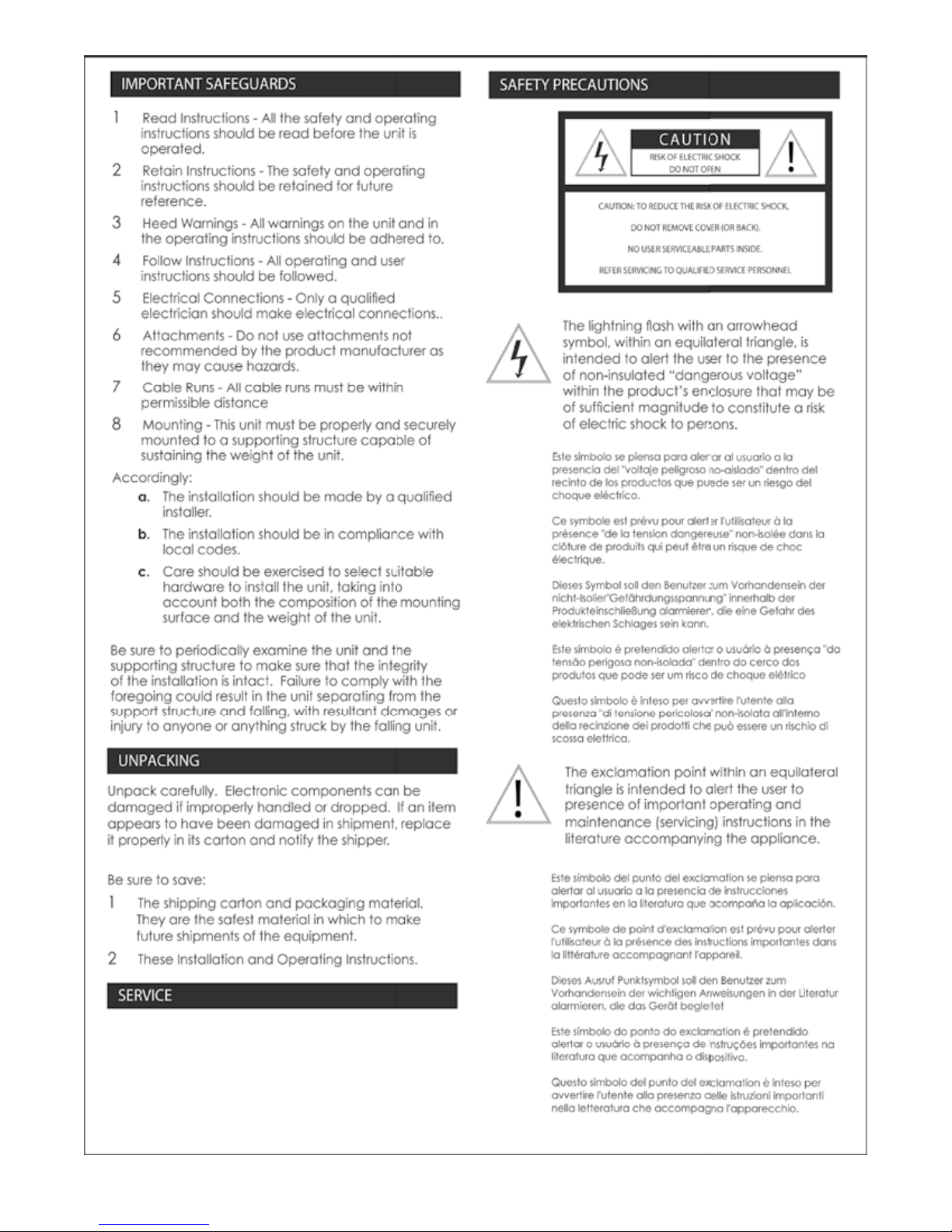
IMPORTANT SAFEGUARDS SAFETY PRECAUTIONS
If technical support or service is needed,
contact Sony at the following number.
TECHNICAL SUPPORT
8:15 AM to 7:30 PM
(EASTERN TIME)
1-800-883-6817
1 Read Instructions - All the safety and operating
instructions should be read before the unit is
operated.
2 Retain Instructions - The safety and operating
instructions should be retained for future
reference.
CAUTION: TO REDUCE THE RISK OF ELECTRIC SHOCK,
3 Heed Warnings - All warnings on the unit and in
the operating instructions should be adhered to.
4 Follow Instructions - All operating and user
instructions should be followed.
REFER SERVICING TO QUALIFIED SERVICE PERSONNEL
5 Electrical Connections - Only a qualied
electrician should make electrical connections..
6 Attachments - Do not use attachments not
recommended by the product manufacturer as
they may cause hazards.
7 Cable Runs - All cable runs must be within
permissible distance
8 Mounting - This unit must be properly and securely
mounted to a supporting structure capable of
sustaining the weight of the unit.
Accordingly:
a. The installation should be made by a qualied
installer.
The lightning ash with an arrowhead
symbol, within an equilateral triangle, is
intended to alert the user to the presence
of non-insulated “dangerous voltage”
within the product’s enclosure that may be
of sufcient magnitude to constitute a risk
of electric shock to persons.
The exclamation point within an equilateral
triangle is intended to alert the user to
presence of important operating and
maintenance (servicing) instructions in the
literature accompanying the appliance.
CAUTION
RISK OF ELECTRIC SHOCK
DO NOT OPEN
DO NOT REMOVE COVER (OR BACK).
NO USER SERVICEABLE PARTS INSIDE.
b. The installation should be in compliance with
local codes.
c. Care should be exercised to select suitable
hardware to install the unit, taking into
account both the composition of the mounting
surface and the weight of the unit.
Be sure to periodically examine the unit and the
supporting structure to make sure that the integrity
of the installation is intact. Failure to comply with the
foregoing could result in the unit separating from the
support structure and falling, with resultant damages or
injury to anyone or anything struck by the falling unit.
UNPACKING
Unpack carefully. Electronic components can be
damaged if improperly handled or dropped. If an item
appears to have been damaged in shipment, replace
it properly in its carton and notify the shipper.
Be sure to save:
1 The shipping carton and packaging material.
They are the safest material in which to make
future shipments of the equipment.
2 These Installation and Operating Instructions.
SERVICE
If technical support or service is needed, contact Sony
at the following number:
TECHNICAL SUPPORT
8:15AM to 7:30PM (Eastern Time)
1-800-883-6817
©2007 Sony Corporation
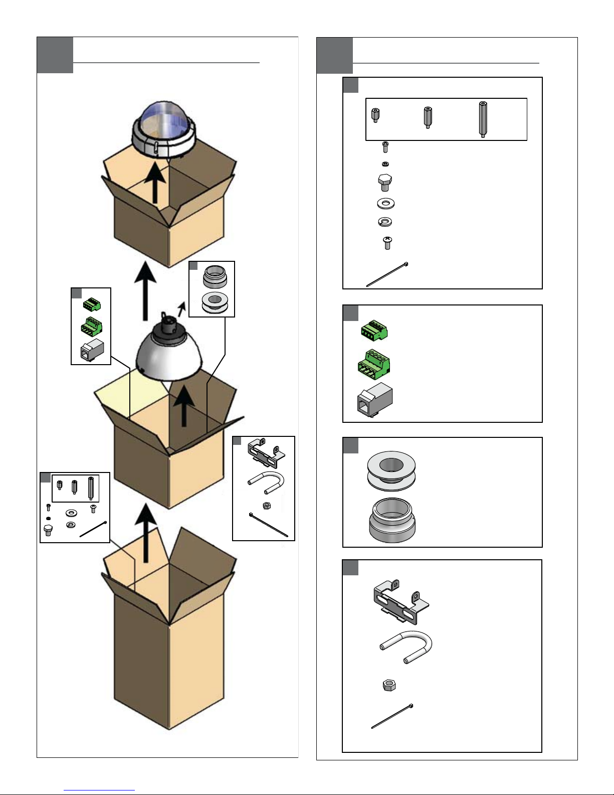
Contents of Box Details
A
B
C
D
(1) Teflon Tape
(4) M3 x 6mm Machine Screw
(1) 1/4 lock washer
(1) 1/4 x 20 Bolt
(3) 8 x 32 x 3/8" bolt
(3) Cable ties
(1) Spacer Packet
(4) M3 lock washers
(1) 1/4 flat washer
(1) 4 Pin Power Connector
(1) 4 Pin Auxiliary Connector
(1) RJ45 Coupling
(4)
(8)
(4)
(1) WiFi Bracket
½”
25mm
1”
50mm
2”
200mm
(1) Pendant Gasket
(2) Cable Tie
(1) 5/16 x 18 U-Bolt
(2) 5/16 x 18 Nut
*
Contents of Box
A
B
C
D
*
*
* Wireless units only
UNI-ONL7C2
UNI-ONL7T2
UNI-INL7C2
UNI-INL7T2
Electrical Specifications
Operating Temperature Specifications
(ONLY AL AIRE LIBRE):
UNI-ONL7C2 y UNI-ONL7T2
26 vatios en 24VAC (calentador y soplador)
Aproximadamente el 25 Watts a 24VAC (Cámara) *
* Consulte con las especificaciones de la cámara aplicable para el consumo
exacto
(ONLY DE INTERIOR):
UNI-INL7C2 y UNI-INL7T2
Vea Las Especificaciones De la Cámara fotográfica.
Herramientas Requeridas: Destornillador PrincipalPhillips
Del Destornillador Principal Plano Del 100"
(ONLY EXTÉRIEURS):
UNI-ONL7C2 et UNI-ONL7T2
26 watts à 24VAC (réchauffeur et ventilateur)
Environ 25 Watts à 24VAC (Camera) *
* Se reporter aux spécifications applicables à la consommation caméra précise
(ONLY D'INTÉRIEUR):
UNI-INL7C2 et UNI-INL7T2
Voir Les Caractéristiques D'Appareil-photo.
Outils Requis: Tournevis Principal Phillips
De Tournevis Principal Plat De 100"
(IM FREIEN ONLY):
UNI-ONL7C2 u. UNI-ONL7T2
26 Watt an 24VAC (Heizung und Gebläse)
Ca. 25 Watt bei 24VAC (Kamera) *
* Wenden Sie sich an geltenden Kamera Angaben zur genauen Verbrauch
(INNENONLY):
UNI-INL7C2 u. UNI-INL7T2
Sehen Sie Kamera-Spezifikationen.
Werkzeuge Erforderten: 100"Flacher Hauptschraubenzieher-
Kreuzkopfhauptschraubenzieher
(ONLY AO AR LIVRE):
UNI-ONL7C2 & UNI-ONL7T2
26 watts em 24VAC (calefator e ventilador)
Cerca de 25 Watts a 24VAC (Câmara) *
* Consulte a Ficha câmera aplicável ao consumo precisa
(ONLY INDOOR):
UNI-INL7C2 & UNI-INL7T2
Veja Especificações Da Câmera.
As Ferramentas Requereram: Chave de fenda Principal
Phillips Da Chave de fenda Principal Lisa Do 100"
(ONLY ESTERNI):
UNI-ONL7C2 & UNI-ONL7T2
26 watt a 24VAC (riscaldatore e ventilatore)
Circa 25 Watt a 24VAC (Camera) *
* Fare riferimento a specifiche fotocamera applicabili per il consumo precisa
(ONLY DELL'INTERNO):
UNI-INL7C2 & UNI-INL7T2
Veda Le Specifiche Della Macchina fotografica
Attrezzi Richiesti: Cacciavite Capo "phillips" Del Cacciavite
Capo Piano Del 100"
-20°C to +50°C (-4°F to +122°F)
(OUTDOOR ONLY):
UNI-ONL7C2 & UNI-ONL7T2
Power 24VAC, Class 2 Only
26 Watts at 24 VAC (Heater and Blower)
Approximately 25 Watts at 24VAC (Camera)*
*
Refer to applicable camera specs for precise consumption
(INDOOR ONLY):
UNI-INL7C2 & UNI-INL7T2
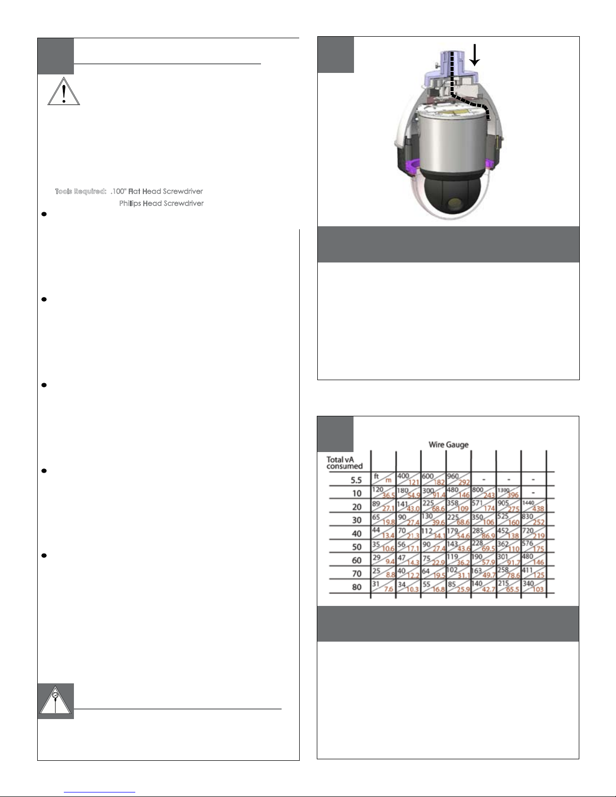
Tools Required:
.100" Flat Head Screwdriver
Phillips Head Screwdriver
See Camera Specifications.
UNINL7C2 &
UNINL7T2
There are no pre-run cables on the indoor
models.
(Proceed to Camera Installation section)
• Hay ningún pre-funciona los cables en los modelos de interior.
(
Continúe con la sección de instalación de la cámara)
• Il y a aucun pré-courent des câbles sur les modèles d'intérieur.
(
Passez à la section Installation de caméra)
• Es gibt kein vor-laufen lassen Kabel auf den Innenmodellen.
(Fahren Sie mit Kamera Installations-Abschnitt)
• Há nenhum pre-funciona cabos nos modelos indoor.
(
Continue na seção Instalação da câmara)
• Ci è nessun pre-fa funzionare i cavi sui modelli dell'interno.
(
Procedere alla sezione di installazione della fotocamera)
MM
AWG
2
,5 ,75 1,0 1,5 2,5 4 6
22 20 18 16 14 12 10
These are recommended maximum distances
for 24VAC with a 10% voltage drop.
• Éstos se recomiendan las distancias máximas para
24VAC con una caída de voltaje del 10%.
• Ceux-ci sont recommandés des distances maximum
pour 24VAC avec une chute de tension de 10%.
• Diese werden maximale Abstände für 24VAC mit
einem 10% Spannungsabfall empfohlen.
• Estes são recomendados distâncias máximas para
24VAC com uma queda de tensão de 10%.
• Questi sono suggeriti distanze massime per 24VAC con
una differenza de potenziale di 10%.
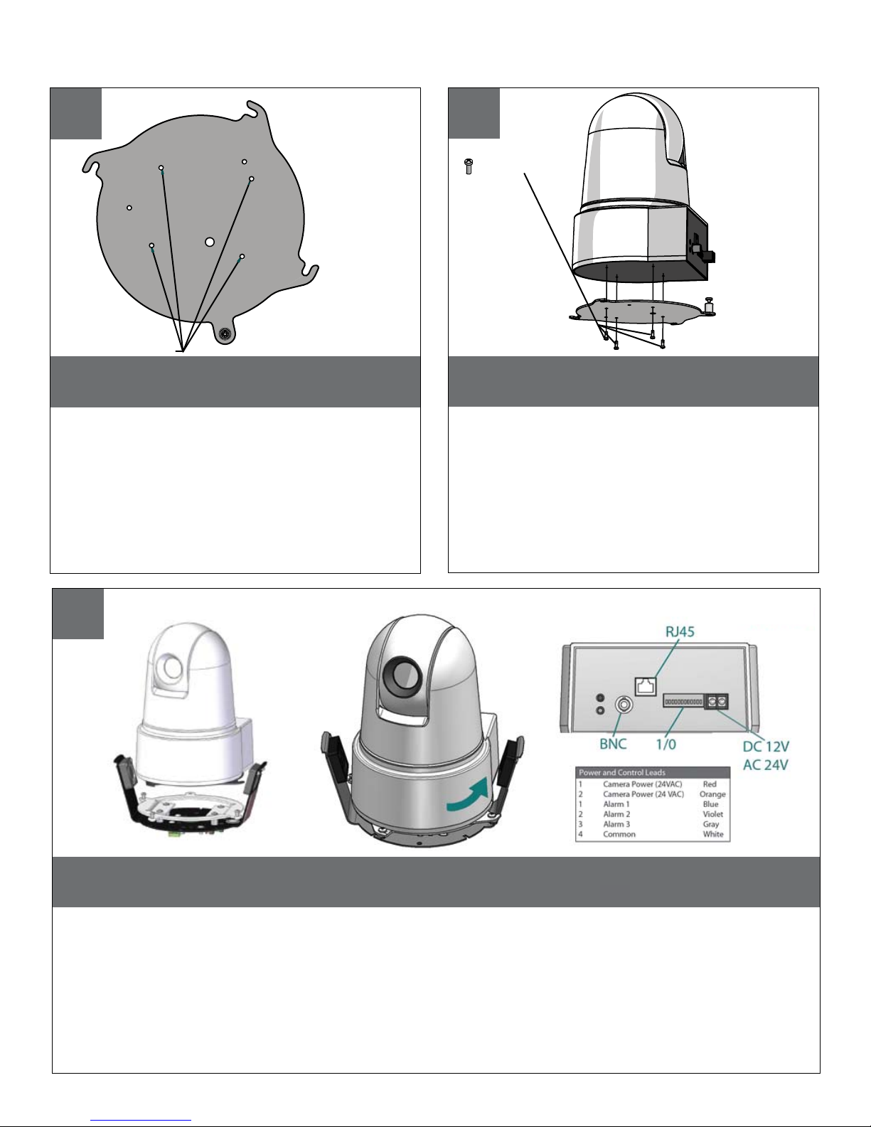
1
2

Remove the quick release plate from the
housing.
• Quite la placa rápida del lanzamiento de la cubierta.
• Enlevez le plat rapide de dégagement du logement.
• Entfernen Sie die schnelle Freigabeplatte vom
Gehäuse.
• Remova a placa rápida da liberação da carcaça.
• Rimuova la piastra rapida del rilascio
SNCRZ25
MOUNTING HOLES
Mount the camera to the plate using the
appropriate pattern.
• Monte la cámara fotográfica a la placa usando el
patrón apropiado.
• Montez l'appareil-photo au plat en utilisant le modèle
approprié.
• Bringen Sie die Kamera zur Platte mit dem passenden
Muster an.
• Monte a câmera à placa usando o teste padrão
apropriado.
• Monti la macchina fotografica alla piastra usando il
modello adatto.
SNCRZ25
(2) 3mm screws
(1) ¼”x 20 bolt
lock washer
1/2” Spacers
or standoffs
Add (4) 1/2” spacers, align tabs in mounting plate and turn counterclockwise then secure.
When completed, go to step 12.
• Añadir (4) 1 / 2 "de separación, se suman las pestañas en la placa de montaje y gire en sentido entonces seguro.
Cuando se haya completado, vaya al paso 12.
• Ajouter (4) 1 / 2 "d'espacement, l'alignement des onglets dans la plaque de montage et de tourner dans le sens
antihoraire sécurisée. Une fois terminé, passez à l'étape 12.
• "Hinzufügen" (4) 1 / 2 "Abstandhalter, Angleichung der Registerkarten in Montageplatte und dann gegen den
Uhrzeigersinn zu sichern. Wenn abgeschlossen, fahren Sie mit Schritt 12 fort.
• Adicionar (4) 1 / 2 "espaçadores, alinhar separadores na placa de montagem e, em seguida, vire à esquerda
segura. Quando concluído, vá para a etapa 12.
• Aggiungi (4) 1 / 2 "Distanziatori, allineare le linguette nella piastra di montaggio e poi girate a garantire antiorario.
Una volta completato, passare al punto 12.
Camera Installation: SNC-RZ25
3
4
SNC-RZ25
5
20.
20.
20.
20
20.
20.
SNC-RZ25
SNCRX550
Mount the camera to the plate using the
appropriate pattern.
• Monte la cámara fotográfica a la placa usando el
patrón apropiado.
• Montez l'appareil-photo au plat en utilisant le
modèle approprié.
• Bringen Sie die Kamera zur Platte mit dem passenden Muster an.
• Monte a câmera à placa usando o teste padrão
apropriado.
• Monti la macchina fotografica alla piastra usando
il modello adatto.
(4) 3mm screws
Remove the quick release plate from the
housing.
• Quite la placa rápida del lanzamiento de la cubierta.
• Enlevez le plat rapide de dégagement du logement.
• Entfernen Sie die schnelle Freigabeplatte vom
Gehäuse.
• Remova a placa rápida da liberação da carcaça.
• Rimuova la piastra rapida del rilascio
dall'alloggiamento.
SNC RX550
MOUNTING HOLES
SNCRX550
Align tabs in mounting plate with the base plate and turn counterclockwise to secure.
NO SPACERS OR STANDOFFS REQUIRED. When completed, go to step 12.
• Alinee las pestañas en la placa de montaje con la placa base y girar en sentido antihorario para seguro. SPACERS O
NO OBLIGATORIO STANDOFFS. Cuando se haya completado, vaya al paso 12.
• Alignez les onglets dans une plaque de montage avec la plaque de base et à assurer son tour dans le sens
antihoraire. SPACERS STANDOFFS OU NON REQUIS. Une fois terminé, passez à l'étape 12.
• Richten Sie Registerkarten in Montageplatte mit der Bodenplatte und dann gegen den Uhrzeigersinn zu sichern. NO
SPACERS ODER Standoffs REQUIRED. Wenn abgeschlossen, fahren Sie mit Schritt 12 fort.
• Alinhar guias na montagem da chapa com base prato e vire à esquerda para garantir. SPACERS OU NÃO STANDOFFS
REQUIRED. Quando concluído, vá para a etapa 12.
• Allineare le linguette nella piastra di montaggio con la piastra di base e girare antiorario per sicurezza. DISTANZIALI
STANDOFFS N O RICHIESTE. Una volta completato, passare al punto 12.
Camera Installation: SNC-RX530 / RX550 / RX570
6
SNC-RX Series
SNC-RX Series
7
8
20.
20.
20.
20.
20.
20
SNC-RX SERIES
 Loading...