

Page 1
UNIVERSAL CONTROL PANEL
UCP-8060
電気製品は、安全のための注意事項を守らないと、
火災や人身事故になることがあります。
本機は電源スイッチを備えていません
本機を設置する際は、電源遮断用として本機の近くの容易に接近できる屋
内配線内に専用ブレーカーまたはスイッチを設けてください。
万一、異常が起きた場合は
このオペレーションマニュアルの「安全のために」に記載された指示に
従って電源を切ってください。
このオペレーションマニュアルには、事故を防ぐための重要な注意事項と
製品の取り扱いかたを示してあります。このオペレーションマニュアルを
よくお読みのうえ、製品を安全にお使いください。お読みになったあと
は、いつでも見られるところに必ず保管してください。
OPERATION MANUAL [Japanese/English]
1st Edition (Revised 1)
Page 2
日本語
安全のために
電気製品は、安全のための注意事項を守らないと、火災や感電などにより死亡や
大けがなど人身事故につながることがあり、危険です。
事故を防ぐために次のことを必ずお守りください。
安全のための注意事項を守る
4 〜 6 ページの注意事項をよくお読みください。
定期点検を実施する
長期間安全に使用していただくために、定期点検を実施することをおすすめしま
す。点検の内容や費用については、ソニーのサービス担当者または営業担当者に
ご相談ください。
故障したら使用を中止する
ソニーのサービス担当者、または営業担当者にご連絡ください。
万一、異常が起きたら
・異常な音、におい、煙が出たら
・ 落下させたら
警告表示の意味
オペレーションマニュアルおよび
製品では、次のような表示をして
います。表示の内容をよく理解し
てから本文をお読みください。
この表示の注意事項を守らないと、
火災や感電などにより死亡や大け
がなど人身事故につながることが
あります。
この表示の注意事項を守らないと、
感電やその他の事故によりけがを
したり周辺の物品に損害を与えた
りすることがあります。
注意を促す記号
m
a 電源を切る。
b 電源コードおよび接続コードを抜く。
c ソニーのサービス担当者、または営業担当者に修理を依頼する。
炎が出たら
m
すぐに電源を切り、消火する。
行為を禁止する記号
行為を指示する記号
2
安全のために
Page 3

目次
日
本
語
警告....................................................................................................................................................4
注意....................................................................................................................................................6
概要............................................................................................................................................................7
特長.................................................................................................................. 7
関連マニュアル.................................................................................................7
システム構成例.................................................................................................8
各部の名称と働き...................................................................................................................................9
前面.................................................................................................................. 9
後面、側面......................................................................................................10
基本操作.................................................................................................................................................11
画面表示と操作...............................................................................................11
オペレーションソフトウェアの起動と終了......................................................11
本機のシャットダウン.....................................................................................12
基本情報の確認...............................................................................................12
オートスタートを設定する..............................................................................12
メモリースティックをフォーマットする.........................................................13
ソフトリセット...............................................................................................13
システムセットアップ.......................................................................................................................13
SYSTEMSETUPUTILITYの起動...............................................................13
各メニュー項目の働き.....................................................................................14
オペレーションソフトウェアのインストール............................................................................15
準備する.........................................................................................................15
インストールする ...........................................................................................16
オペレーションソフトウェアのアップデート............................................................................18
準備する.........................................................................................................19
アップデートする ...........................................................................................19
オペレーションソフトウェアの削除 .............................................................................................20
オペレーションソフトウェアのプロテクト.................................................................................21
機器情報の確認....................................................................................................................................21
システムファイルのアップデート..................................................................................................22
準備する.........................................................................................................22
アップデートする ...........................................................................................22
メモリースティックを使う........................................................................................................23
メモリースティックについて.....................................................................23
お手入れ.................................................................................................................................................25
仕様.........................................................................................................................................................26
目次
3
Page 4
下記の注意を守らないと、火災や感電により死亡や大けが
につながることがあります。
指定された電源コードを使用する
指定以外の電源コードを使用すると、感電や故障の原因となることがあります。
電源コードのプラグ及びコネクターは突き当たるまで差し込む
真っ直ぐに突き当たるまで差し込まないと、火災や感電の原因となります。
お手入れを始める前に専用ブレーカーを off し、電源プラグを抜
く
電源を接続したままお手入れをすると、感電の原因となることがあります。
移動の際は電源コードや接続コードを抜く
コード類を接続したまま本機を移動させると、コードに傷がついて火災や感電の
原因となることがあります。
外装をはずさない、改造しない
外装をはずしたり、改造したりすると、感電の原因となります。
内部の調整や設定及び点検を行う必要がある場合は、必ずサービストレーニング
を受けた技術者にご依頼ください。
電源コードや接続コードを傷つけない
電源コードや接続コードを傷つけると、火災や感電の原因となることがありま
す。
・ 電源コードを加工したり、傷つけたりしない。
・ 重いものをのせたり、引っ張ったりしない。
・ 電源コードを抜くときは、必ずプラグを持って抜く。
油煙、湯気、湿気、ほこりの多い場所には設置しない
上記のような場所や、この取扱説明書に記されている使用条件以外の環境に設置
すると、火災や感電の原因となることがあります。
4
警告
Page 5
内部に水や異物を入れない
水や異物が入ると火災や感電の原因となることがあります。
万一、水や異物が入ったときは、すぐに電源を切り、電源コードや接続コードを
抜いて、ソニーのサービス担当者または営業担当者にご相談ください。
事故を防ぐためにサービストレーニングを受けた技術者以外はサー
ビスを行わない
機器内部に手を触れると、感電やけがの原因となります。
警告
5
Page 6
下記の注意を守らないと、けがをしたり周辺の物品に損害を与えること
があります。
安定した場所に設置する
製品が倒れたり、搭載した機器が落下してけがをすることがあります。
充分な強度がある水平な場所に設置してください。
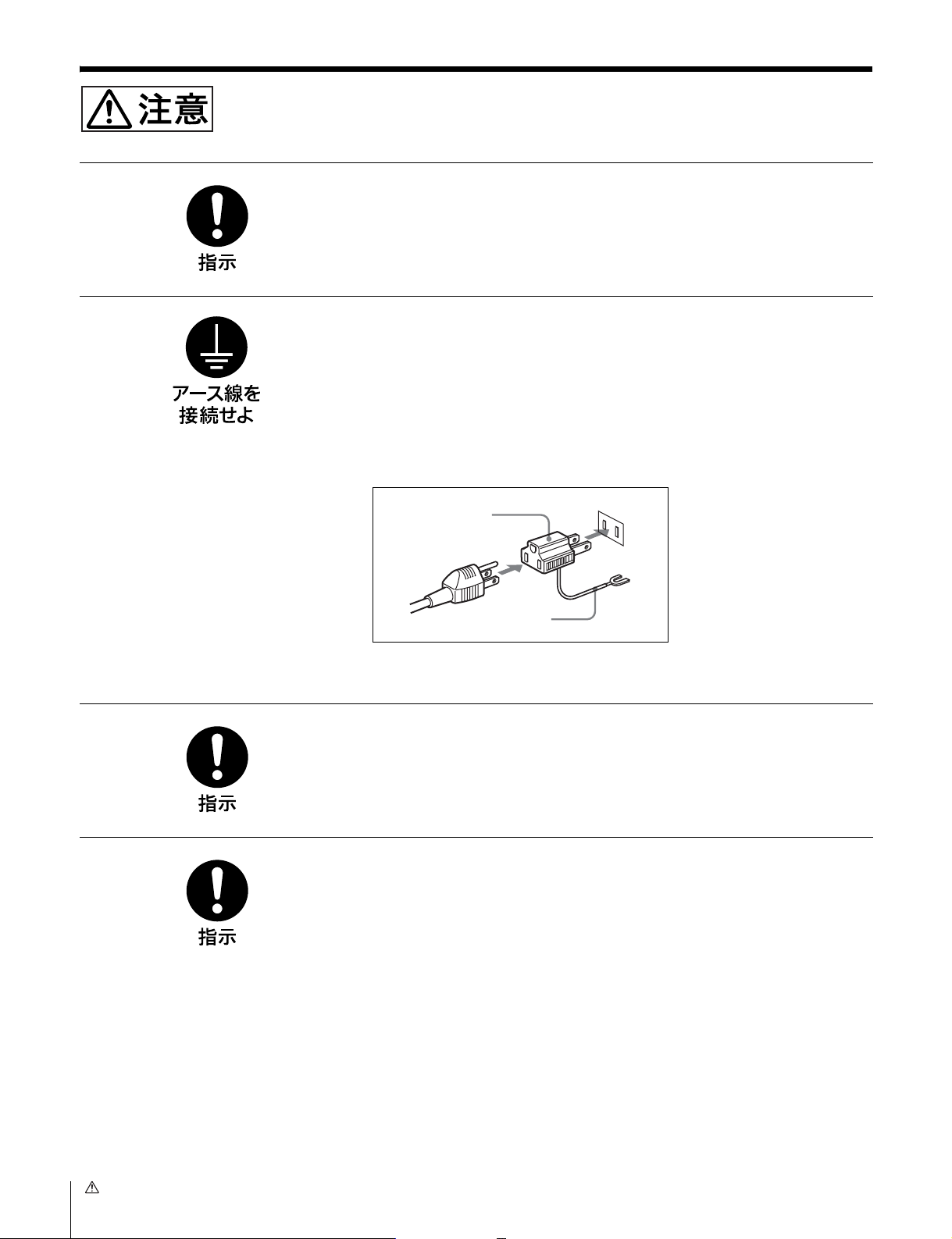
安全アースを接続する
安全アースを接続しないと、感電の原因となることがあります。
次の方法でアースを接続してください。
・ 電源コンセントが 3 極の場合
付属の電源コードを使用することで安全アースが接続されます。
・ 電源コンセントが2極の場合
付属の3極→2極変換プラグを使用し、変換プラグから出ている緑色のアース
線を建物に備えられているアース端子に接続してください。
変換プラグ
アース線
安全アースを取り付けることができない場合は、ソニーのサービス担当者、また
は営業担当者にご相談ください。
コード類は正しく配置する
電源コードや接続ケーブルは、足に引っかけると本機の落下や転倒などによりけ
がの原因となることがあります。
充分注意して接続・配置してください。
ラックに確実に固定する。
機器のラックアングルのねじを締め忘れると機器が落下してけがをすることがあ
ります。
6
注意
Page 7

概要
ユニバーサルコントロールパネル UCP‑8060 は、ネット
ワークを介して PFV‑SP シリーズの IF プロセッサーや
MVS シリーズのマルチフォーマットスイッチャーシステム
などに接続して、各機器の設定や制御、キーヤー調整を行う
など、幅広い用途に柔軟に対応できる汎用リモートコント
ロールパネルです。コントロールする機器用のオペレーショ
ンソフトウェアをインストールして使用します。
特長
幅広い用途に使用可能な汎用コントロールパネル
コントロールする機器のオペレーションソフトウェアをイン
ストールすることにより、接続した機器に応じた様々な操作
が1台のパネルで実行できます。また、ネットワークにより
1台のパネルで複数の機器の遠隔制御や状態監視が可能にな
ります。以下のソニー製品をコントロールすることができま
す。
・ PFV‑SP シリーズプロセッサー/ HKSP シリーズオプ
ションボード(DATA‑LAN 使用)
・ MVS‑8000 シリーズスイッチャー(DATA‑LAN 使用)
迅速かつ確実な操作性
ジョグローラー、ジョグボタン、調整つまみ、ファンクショ
ンボタンでの操作に加え、タッチパネルを併用して、迅速で
確実な操作性を実現しています。さらにタッチパネルを押し
た際に指に振動が得られるタッチエンジン
作時のストレスを軽減しています。タッチエンジンの機能は
OFF にすることもできます。また、レイヤーの浅いメ
ニュー構成、複数のオペレーションソフトウェアでの共通の
操作性など、使い易さにも配慮した設計になっています。
TM
を採用し、操
関連マニュアル
ユーザーガイド
オペレーションソフトウェアを使った詳しい操作方法は、
ユーザーガイドをご覧ください。
メモリ−スティック1)スロットを装備
メモリ−スティックを使用して、オペレーションソフト
ウェアをインストールしたり、設定データを保存することが
できます。
1) 本機で使用可能なメモリ−スティックは、メモリ−スティックと
メモリ−スティック PRO、マジックゲートメモリ−スティックです。
詳しくは、「メモリースティックを使う」(23 ページ)をご覧くださ
い。
小型・薄型設計
高さ 3 ユニット、幅は約 2/3 ラックと小型・薄型で、設置
場所の自由度が高い設計になっています。机上、操作卓への
組み込み、19 インチラックマウントなど、様々な状況で使
用することができます。将来発売予定のオプションモジュー
ルを追加することもできます。
概要
7
Page 8
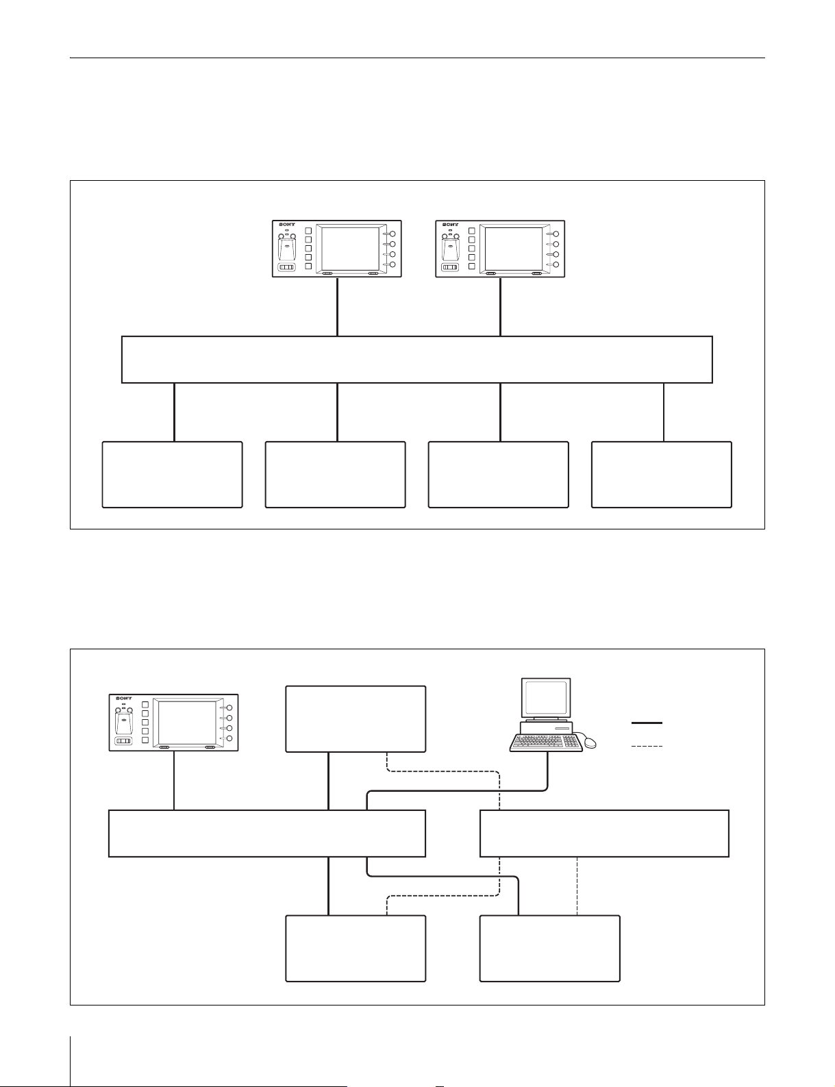
システム構成例
PFV‑SP シリーズと UCP‑8060 との構成
PFV‑SP シリーズを UCP‑8060 から DATA‑LAN でコント
ロールする最も一般的な使用例です。
UCP‑8060
イーサネットスイッチ(DATA)
PFV‑SP
PFV‑SP PFV‑SP PFV‑SP
UCP‑8060 と MVS シリーズとの構成
UCP‑8060 を MVS パネルのサテライトパネルとして使用
し、MVS システム内のキーヤーをリモートコントロールす
る用途の例です。
UCP‑8060
UCP‑8060
イーサネットスイッチ(DATA)
a) 各 LAN(DATA、CTRL)は、それぞれ
別のイーサネットスイッチに接続してく
ださい。ただし、1つのイーサネットス
イッチで各 LAN を接続することもでき
ます。
概要
8
MVS
センターコントロール
パネル
a)
PFV‑SP
(MVS の外付けキーヤー)
システムマネージャー
イーサネットスイッチ(CTRL)
MVS
プロセッサー
:DATA‑LAN
:CTRL‑LAN
a)
Page 9
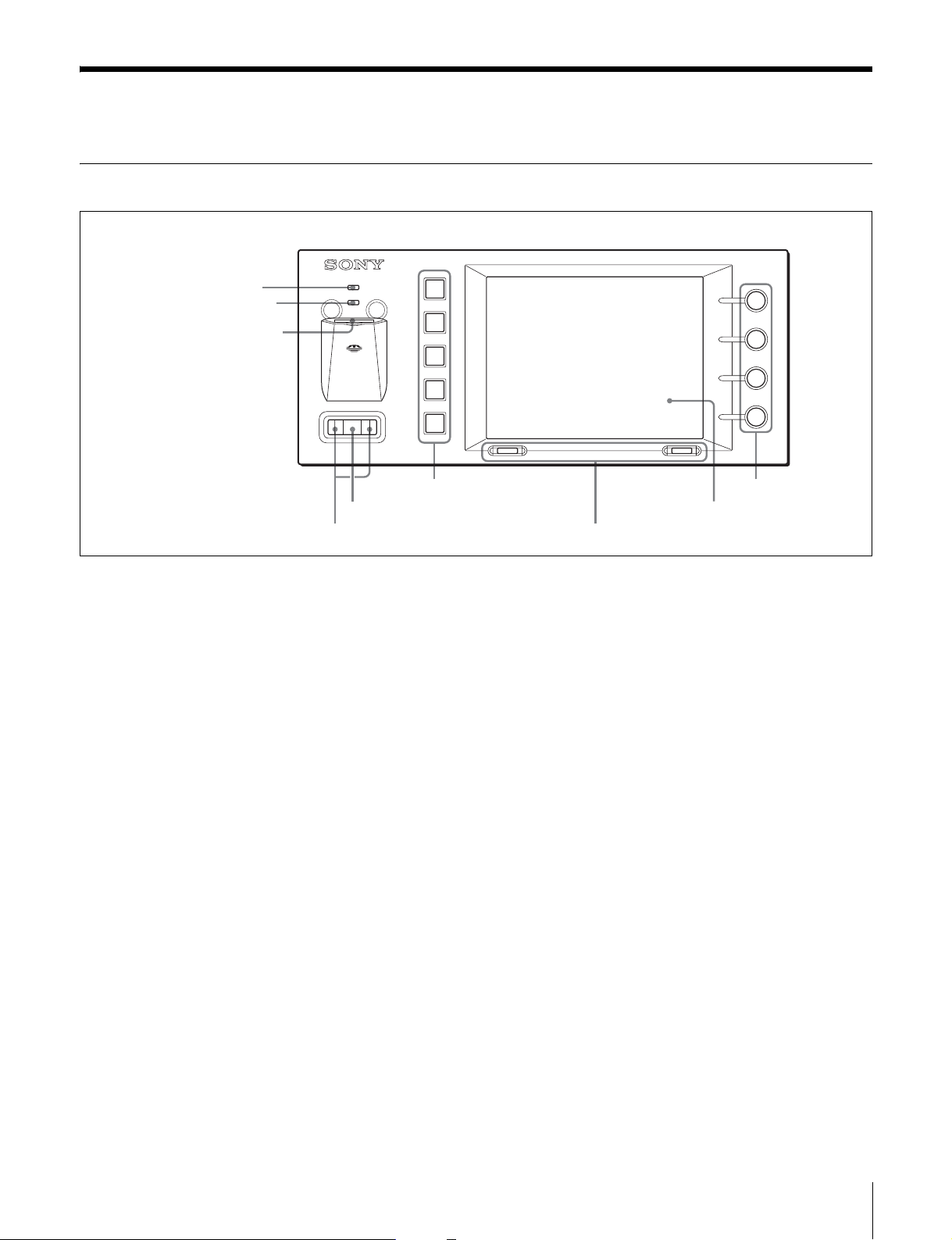
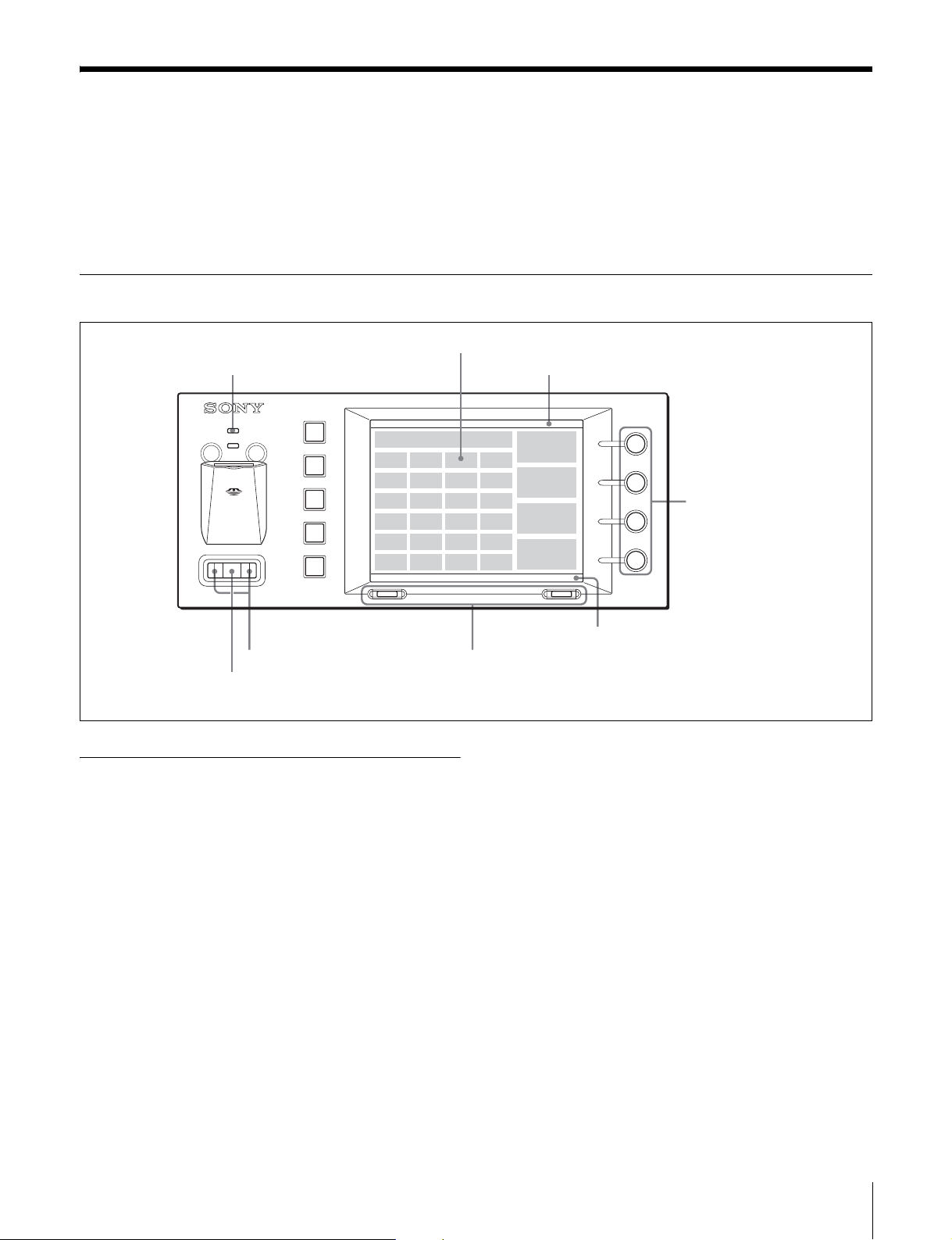
各部の名称と働き
前面
1 システムインジケーター
2 ステータスインジケーター
3 メモリースティックスロット
SYSTEM
6 ファンクションボタン
5 ジョグローラー
4 ジョグ L、R ボタン
a システムインジケーター
赤、オレンジまたは緑色に点灯し、システムの動作状態を表
示します。
電源が供給されると赤に、システムがスタートするとオレン
ジに、ハードウェアの設定が完了すると緑色に点灯します。
電源供給時に上記の遷移が行われず、赤またはオレンジの点
灯が続いている場合は、ハードウェアまたはシステムファイ
ルの異常が考えられます。
b ステータスインジケーター
メモリ−スティックスロットへのアクセス状態や、機器内部
の状態を赤、オレンジまたは緑色の点灯、点滅で表示しま
す。
c メモリースティックスロット
メモリースティックの挿入口です。ラベル面を上にして挿入
します。
◆ 詳しくは、本機の InstallationManual または使用するオペ
レーションソフトウェアに付属のUser'sGuide をご覧くださ
い。
d ジョグ L、R ボタン
左側をジョグ L ボタン、右側をジョグ R ボタンと呼びます。
階層の移動などに使用します。
UCP-8060
9 調整つまみ
8 表示窓
7 セレクト L、R ボタン
e ジョグローラー
ローラーを前後に回転し、項目の選択や数字の変更をしま
す。またローラーを押すと、選択した項目を決定します。
◆ 詳しくは、使用するオペレーションソフトウェアに付属の
User'sGuide をご覧ください。
f ファンクションボタン
上からファンクションボタン 1、2、..5 と呼びます。操作
の状態により、緑、オレンジ、赤に点灯します。ボタンの機
能は、使用するオペレーションソフトウェアによって異なり
ます。
◆ 詳しくは、使用するオペレーションソフトウェアに付属の
User'sGuide をご覧ください。
g セレクト L、R ボタン
左側をセレクト L ボタン、右側をセレクト R ボタンと呼び
ます。タスクバー(11 ページ参照)の各ボタンに対応する
位置に表示される機能を実行します。主に画面の切り換えに
使用します。
◆ 詳しくは、使用するオペレーションソフトウェアに付属の
User'sGuide をご覧ください。
◆ 詳しくは、使用するオペレーションソフトウェアに付属の
User'sGuide をご覧ください。
各部の名称と働き
9
Page 10
h 表示窓
メニューやデータを表示します。画面はタッチパネルになっ
ています。表示されている項目に触れて選択することができ
ます。表示される内容は、使用するオペレーションソフト
ウェアによって異なります。
◆ 詳しくは、使用するオペレーションソフトウェアに付属の
User'sGuide をご覧ください。
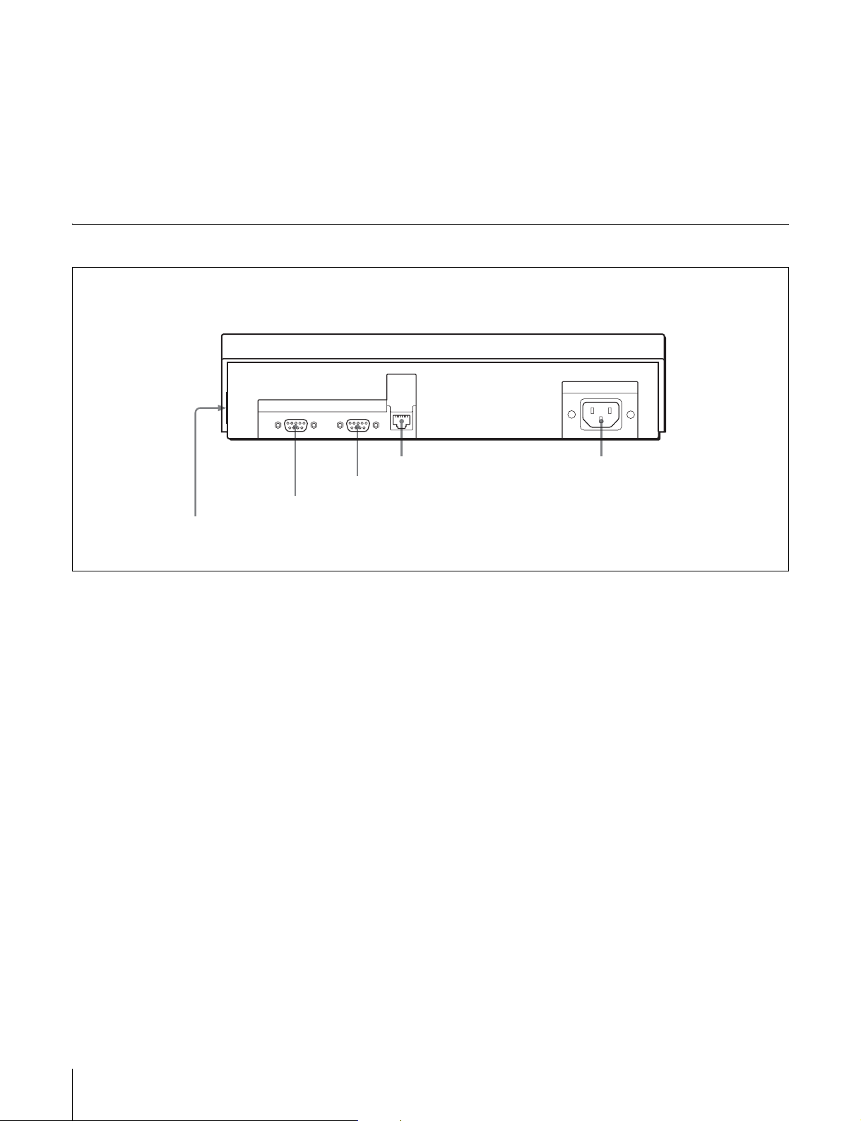
後面、側面
i 調整つまみ
上からつまみ 1、2、3、4 と呼びます。パラメーターの調
整などに使用します。つまみの機能は、使用するオペレー
ションソフトウェアによって異なります。
◆ 詳しくは、使用するオペレーションソフトウェアに付属の
User'sGuide をご覧ください。
EXT
PANEL1
1EXTPANEL2 端子
2EXTPANEL1 端子
RS-232C
3RS‑232C 端子
a EXTPANEL2(エクステンションパネル2)端子
(20 ピン、側面)
将来の拡張時にカバーをはずして使用します。電源供給ピン
(500mA/5V)も備えています。
b EXTPANEL1(エクステンションパネル1)端子
(D‑sub9 ピン)
将来の拡張時に使用します。
c RS‑232C 端子(D‑sub9 ピン)
メンテナンス時に使用します。
DATA
LAN
4DATALAN 端子 5-ACIN 端子
◆ イーサネットスイッチの詳しい設定方法は、イーサネットスイッ
チに付属の取扱説明書をご覧ください。
-AC IN
e -ACIN(AC 電源入力)端子(3ピン)
別売りの電源コードで 100 〜 240V の AC 電源に接続しま
す。電源コードは、使用する地域で指定されている安全規格
に適合するものをご使用ください。
d DATALAN(データ LAN)端子(RJ‑458 ピン)
イーサネット1)スイッチと接続します。イーサネットス
イッチに接続された IF プロセッサー PFV‑SP シリーズや
MVS‑8000 システムのセンターコントロールパネルなどと
の間でネットワークを形成し、機器間相互の通信を行いま
す。
使用できるイーサネットスイッチについては、ソニーのサー
ビス担当者にお問い合わせください。
1) イーサネットは XEROX 社の登録商標です。
◆ イーサネットスイッチの接続については「システム構成例」(8
ページ)をご覧ください。
各部の名称と働き
10
Page 11
基本操作
電源が供給されると、システムインジケーターが赤色に点灯
します。機器内部の初期化が正常に終了すると緑色に点灯
し、1 分程するとメイン画面が表示されます。表示窓に表示
されるメニューの選択や各種の設定は、ジョグローラー、
画面表示と操作
選択したい項目に触れる。
システムインジケーター タイトルバー
SYSTEM
ジョグボタン、セレクトボタン、調整つまみを使って行いま
す。表示窓はタッチパネルになっています。画面に表示され
ている項目に触れて選択することもできます。
UCP-8060
回して、画面右に表示される
調整値表示エリアに表示され
る項目を調整する。
押して設定する位置を移動する。
回して選択し、押して決定する。
オペレーションソフトウェアの起動と 終了
起動するには
1
ジョグローラーを回して、起動したいオペレーション
ソフトウェアを MainScreen(以下メイン画面とす
る)で選択する。
2
ジョグローラーを押すか、セレクト R ボタン (Launch)
を押す。
選択したオペレーションソフトウェアが起動します。
メイン画面で、起動したいオペレーションソフトウェアを押
して起動することもできます。
タスクバー
タスクバーに表示される機能を実行する。
終了するには
1
オペレーションソフトウェアのトップ画面でセレクト L
ボタン (Option) を押す。
OptionMenu が表示されます。
2
ジョグローラーを回して ExitApplicationを選択する。
3
ジョグローラーを押す。
オペレーションソフトウェアが終了し、本機のメイン
画面が表示されます。
ExitApplication を押して終了することもできます。
基本操作
11
Page 12
本機のシャットダウン
本機の電源を切る前に、次の手順でシステムの終了処理を
行ってください。
1
メイン画面でセレクト L ボタン (Menu) を押す。
メニュー画面が表示されます。
2
ジョグローラーを回して Shutdown を選択する。
3
ジョグローラーを押す。
Basic Information of System [BIOS] UTILITY
Version : xxx Bulid date : xxx xx xxxx xx:xx:xx
FPGA Revosopm : xxx memorystick host controller : xxx
MAC Address : 08:00:46:xx:xx:xx
IP Address : 10.129.7.1
Netmask : 255.192.0.0
Gateway : 10.128.0.0
DNS : 0.0.0.0
MEMORY SIZE : xxMByte
Reboot Memory Stick Format
Shutdown 画面が表示され、終了処理が完了します。
ご注意
Shutdown 画面が表示されるまでは本機の電源を切らない
でください。
シャットダウンを取り消したいときは
セレクト L ボタン (Back) を押します。
ソフトリセットを行いたいときは
セレクト R ボタン (Reboot) を押します。
BIOSUtility を起動したいときは
ファンクションボタン 1 を押したまま、セレクト R ボタン
(Reboot) を押し、ファンクションボタン 1 が点灯したら指
を離します。
UPDATEUtility を起動したいときは
ファンクションボタン 2 を押したまま、セレクト R ボタン
(Reboot) を押し、ファンクションボタン 2 が点灯したら指
を離します。
メイン画面に戻るには
セレクト L ボタン(Reboot)を押します。
オートスタートを設定する
あらかじめオペレーションソフトウェアにオートスタートを
設定しておくと、本機に電源を入れたとき、メイン画面を表
示後、自動的にオペレーションソフトウェアのトップ画面が
表示されます。
オートスタートを設定するには
次の手順でオートスタートを設定します。
1
メイン画面で、オートスタートを設定したいオペレー
ションソフトウェアを選択する。
2
セレクト L ボタン(Menu)を押す。
メニュー画面が表示されます。
3
AutoStart を選択する。
基本情報の確認
ファンクションボタン 1 を押したまま、セレクト L、R ボタ
ンを同時に 3 秒以上押し、ファンクションボタン 1 が点灯
したら指を離します。
BasicInformationofSystem[BIOS]Utility が起動し、
FPGA バージョン、MAC アドレスなど本体の基本的な情報
が表示されます。
Shutdown 画面から起動することもできます。
◆ 詳しくは「本機のシャットダウン」(12ページ)をご覧くださ
い。
基本操作
12
AutoStart 画面が表示されます。
Auto Start
ON
OFF
Exit Save
4
ON を選択する。
5
セレクト R ボタン(Save)を押す。
メニュー画面が表示されます。
Page 13
6
セレクト L ボタン(Back)を押す。
メイン画面が表示されます。
オートスタートを解除するには
オートスタートの設定と同じ手順で操作し、手順 4 でON
の代わりに OFF を選択します。
また、ほかのオペレーションソフトウェアでオートスタート
を ON に設定すると、前に設定したオートスタートは自動
的に解除されます。
オートスタートを中断するには
本機に電源を入れた後、メイン画面が表示されてから約 2
秒以内にセレクト L ボタン(Menu) を押すと、オートスター
トを中断することができます。
メモリースティックをフォーマットす る
1
BIOSUtility を起動する。
◆ 起動方法については、「基本情報の確認」(12 ページ)をご
覧ください。
2
メモリースティックをラベル面を上にしてメモリース
ティックスロットに挿入する。
3
セレクト R ボタン(MemoryStickFormat)を押す。
システムセットアップ
SYSTEMSETUPUTILITY で下記の項目を実行できます。
・ デバイスコントロール
― 表示窓の明るさの調整
― ブザー音の音量調整とテスト
― タッチエンジンの感度調整
― タッチパネルに触れたときのブザー音の ON/OFF
・ 日付、時刻の設定
・ TCP/IP アドレスの設定
・ 表示とタッチパネルの位置関係の調整
・ お絵書きテスト
・ 自己診断
SYSTEMSETUPUTILITY の起動
メイン画面で SYSTEMSETUPUTILITY を選択します。
SYSTEMSETUPUTILITY が起動し、SYSTEMSETUP
UTILITY 画面が表示されます。
SYSTEM SETUP UTILITY Version 1.xx
Device Control
Adjust Time
Set TCP/IP Config
Calibrate Touch Panel
Scribble T est
Self Diagnosis
4
フォーマットの種類 (Full または Quick)を選択する。
通常はセレクト R ボタン (Quick) を押してください。
5
セレクト R ボタン(YES)を押す。
画面にDONEと表示されると、フォーマットが完了し
ます。同時に MSSONY/PRO/UCP というフォルダーが作
成されます。
ご注意
フォーマットを実行すると、既存のファイルはすべて削除さ
れます。
ソフトリセット
セレクト L、R ボタンを同時に 3 秒以上押し続けると、
UCP‑8060 をソフトリセットすることができます。
Exit 03:13:00
必要な項目を選択してください。
◆ 選択のしかたについては、「基本操作」(11ページ)をご覧くだ
さい。
システムセットアップ
13
Page 14

各メニュー項目の働き
DeviceControl
各項目は次の手順で調整します。
1
ジョグローラーを回して調整項目を選択する。
2
ジョグボタンを押して調整する。
3
ジョグローラーを押して調整値を確定する。
4
必要な項目の調整が終了したら、セレクト R ボタンを押
す。
調整値が保存されます。
調整値を取り消したいときは、セレクト L ボタンを押しま
す。
3
設定が終了したら、セレクト R ボタンを押す。
調整値が保存されます。
調整値を取り消したいときは、セレクト L ボタンを押しま
す。
SetTCP/IPConfig.
IPAddress、Netmask、Gateway、DNSの数値は工場出
荷時に設定されていますが、必要に応じて次の手順で変更す
ることができます。
1
ジョグローラーを押して変更したい項目を選択する。
2
ジョグ L、R ボタンを押して変更したい桁を選択する。
3
ジョグローラーを回して数値を設定する。
4
設定が終了したら、セレクト R ボタンを押す。
・LCDBrightness
表示窓の明るさを 1 〜 7 の 7 段階で調整します。デフォル
トは3です。画面下の Sample 画像を参考にして、明る
さを調整することができます。
・F‑KEYLEDBrightness
ファンクションボタンの明るさを調整します。デフォルトは
最大値5です。画面下の Sample 画像を参考にして、明
るさを調整することができます。
・SoundControl
ブザーの音量を調整します。デフォルトは3です。
音量を調整すると、SoundTest が実行されます。
・SoundTest
SoundControl で設定した音量のテスト中であることを表
示します。
・TouchEngineForce:ON/HIGH
タッチエンジンの感度調整を行います。OFF、ON/LOW、
ON/MIDDLE、ON/HIGH の4段階に調整ができます。
設定値が保存されます。
5
設定値を反映させるために、セレクト R ボタンを押す。
システムを再起動します。
設定値を取り消したいときは、セレクト L ボタンを押しま
す。
工場出荷時の設定に戻したいときは、Default を選択しま
す。
CalibrateT ouchPanel
タッチパネルの四隅に順番に表示される十字マークの中心を
ペンまたは指のつめなどで押します。画面とタッチパネルの
位置関係を較正することができます。
途中でやり直したいときは、十字マークから離れた場所を十
字マークが左上に表示されるまで押します。それまでの動作
はエラーとして処理され、やり直すことができます。
ScribbleTest
お絵描き機能で、タッチパネルの動作状態を確認します。ペ
ンなどをタッチパネル上で動かすと軌跡が表示されます。
・TouchBeepControl
タッチパネルに触ると鳴るブザー音を ON/OFF します。
AdjustTime
日時を設定します。設定した日時は電源を切っても約 7 日
間程度は保持されます
1
ジョグ L、R ボタンを押して設定する桁を選択する。
2
ジョグローラーを回して数値を設定する。
システムセットアップ
14
SelfDiagnosis
ジョグローラー、ジョグボタン、ファンクションボタン、調
整つまみの動作をチェックします。
Page 15

オペレーションソフトウェ アのインストール
準備する
1
コンピューターを使って、メモリースティックまたは
HTTP サーバーにオペレーションソフトウェアをコ
ピーする。
UCP‑8060 には、工場出荷時にいくつかのオペレーション
ソフトウェアがインストールされています。他のオペレー
ションソフトウェアを使用したい場合は、以下の手順に従っ
てインストールしてください。システムファイルをアップ
デートしたときも、オペレーションソフトウェアの再インス
トールが必要です。
インストールの方法には、メモリースティックを使う方法
と、インターネット (HTTP サーバー ) を使う方法がありま
す。
◆ オペレーションソフトウェアの入手方法については、ソニーの営
業担当にお問い合わせください。
ご注意
オペレーションソフトウェアを格納するメモリーの容量には
制限があります。新しくインストールするオペレーションソ
フトウェアの容量によっては、すでにインストールされてい
るオペレーションソフトウェアを削除する必要があります。
◆ 空き容量については「機器情報の確認」(21 ページ)をご覧く
ださい。
◆ 削除の方法については、「オペレーションソフトウェアの削除」
(20 ページ)をご覧ください。
メモリースティックにコピーする場合 MSSONY/
PRO/UCP というフォルダーを作り、UCP フォルダー
の下にコピーしてください。
本機でメモリースティックをフォーマットすると指定
のフォルダーが自動的に作成されます。
ご注意
ASCII コード以外の文字を使用したファイル名やフォ
ルダ
ーが含まれていると、インストールできないこと
があります。
2
本機の電源を入れる。
メイン画面が表示されます。
◆ HTTP サーバーの IP アドレスおよびネットワーク接続に関する
詳細は、ネットワーク管理者に確認してください。
準備するもの
・ パーソナルコンピューター(メモリースティックを使う場
合は、メモリースティックへファイルコピーが可能なも
の)
・ インストールするオペレーションソフトウェア ( 拡張子が
jar および jad の2つのファイル )
メモリースティックを使ってインストールする場合
・ メモリースティック
オペレーションソフトウェアのインストール
15
Page 16

インストールする
メモリースティックを使ってインストールす
るには
1
オペレーションソフトウェアをコピーしたメモリース
ティックを挿入する。
ご注意
データの読み込み/書き込み中は、電源を切ったり、
メモリースティックを抜いたりしないでください。
ファイルが壊れることがあります。
5
メモリースティックを抜く。
6
セレクト R ボタン(Restart)を押す。
2
セレクト L ボタン (Menu) を押す。
メニュー画面が表示されます。
3
ジョグローラーで InstallSettings を選択し、セレクト
R ボタン(Enter)を押す。
InstallSettings 画面が表示されます。
4
ジョグローラーで MemoryStick を選択し、セレクトR
ボタン(Save)を押す。
メニュー画面が表示されます。
以降の手順は、本機にオペレーションソフトウェアがインス
トールされているかどうかで操作が異なります。
オペレーションソフトウェアがインストールされている場合
1
ジョグローラーで Install を選択する。
2
セレクト R ボタン(Enter)を押す。
Install 画面が表示されます。メモリースティック内の
拡張子が jad のファイルが表示されていることを確認
してください。
インストールするファイル名に大文字と小文字が混在
していても問題なくインストールできます。
3
インストールするオペレーションソフトウェアをジョ
グローラーで選択し、セレクト R ボタン(Go)を押
す。
メイン画面が表示されます。インストールしたオペ
レーションソフトウェアの名前が表示されていること
を確認してください。
オペレーションソフトウェアがインストールされていない場
合
1
セレクト L ボタン(Back)を押す。
メイン画面が表示されます。
2
セレクト R ボタン(Install)を押す。
Install 画面が表示されます。メモリースティック内の
拡張子が jad のファイルが表示されていることを確認
してください。
3
インストールするオペレーションソフトウェアをジョ
グローラーで選択し、セレクト R ボタン(Go)を押
す。
インストールするオペレーションソフトウェアの情報
が表示されます。
4
表示された内容が正しければセレクト R ボタン(Yes)
を押す。
インストールが開始されます。データの読み込み/書
き込み中は、ステータスインジケーターが点灯または
点滅します。
インストールが完了すると、インストールが成功した
というメッセージが画面に表示されます。
インストールするオペレーションソフトウェアの情報
が表示されます。
4
表示された内容が正しければセレクト R ボタン(Yes)
を押す。
インストールが開始されます。データの読み込み/書
き込み中は、ステータスインジケーターが点灯または
点滅します。
インストールが完了すると、インストールが成功した
というメッセージが画面に表示されます。
オペレーションソフトウェアのインストール
16
ご注意
データの読み込み/書き込み中は、電源を切ったり、
メモリースティックを抜いたりしないでください。
ファイルが壊れることがあります。
5
メモリースティックを抜く。
6
セレクト R ボタン(Restart)を押す。
メイン画面が表示されます。インストールしたオペ
レーションソフトウェアの名前が表示されていること
を確認してください。
Page 17

インターネットを使ってインストールするに
は
1
本機がインターネットに接続されていることを確認す
る。
2
セレクト L ボタン (Menu) を押す。
メニュー画面が表示されます。
6
表示された内容が正しければセレクト R ボタン(Yes)
を押す。
インストールが開始されます。データの読み込み/書
き込み中は、ステータスインジケーターが点灯または
点滅します。
インストールが完了すると、インストールが成功した
というメッセージが画面に表示されます。
3
ジョグローラーで InstallSettings を選択し、セレクト
R ボタン(Enter)を押す。
InstallSettings 画面が表示されます。
4
ジョグローラーで Internet を選択する。
ここで URL アドレスを設定しておくと、インストール
するときに毎回 URL を入力する必要がなくなります。
◆ URL アドレスの設定ついては、「URL アドレスを設定する
には」(18ページ)をご覧ください。
5
セレクト R ボタン(Save)を押す。
メニュー画面が表示されます。
以降の手順は、本機にオペレーションソフトウェアがインス
トールされているかどうかで操作が異なります。
オペレーションソフトウェアがインストールされている場合
1
ジョグローラーで Install を選択する。
2
セレクト R ボタン(Enter)を押す。
Install 画面が表示されます。
3
タスクバーのキーボードアイコンを押す。
キーボードが表示されます。
ご注意
データの読み込み/書き込み中は、電源を切らないで
ください。ファイルが壊れることがあります。
7
セレクト R ボタン(Restart)を押す。
メイン画面が表示されます。インストールしたオペ
レーションソフトウェアの名前が表示されていること
を確認してください。
オペレーションソフトウェアがインストールされていない場
合
1
セレクト L ボタン(Back)を押す。
メイン画面が表示されます。
2
セレクト R ボタン(Install)を押す。
Install 画面が表示されます。
3
タスクバーのキーボードアイコンを押す。
キーボードが表示されます。
4
インストールするオペレーションソフトウェアが格納
されている URL アドレスとオペレーションソフトウェ
アのファイル名を入力し、セレクト R ボタン(OK)を
押す。
4
インストールするオペレーションソフトウェアが格納
されている URL アドレスとオペレーションソフトウェ
アのファイル名を入力し、セレクト R ボタン(OK)を
押す。
ご注意
オペレーションソフトウェアのファイル名は必ず拡張
子が jad のものを指定してください。
5
セレクト R ボタン(Go)を押す。
インストールするオペレーションソフトウェアの情報
が表示されます。
ご注意
オペレーションソフトウェアのファイル名は必ず拡張
子が jad のものを指定してください。
5
セレクト R ボタン(Go)を押す。
インストールするオペレーションソフトウェアの情報
が表示されます。
オペレーションソフトウェアのインストール
17
Page 18

6
表示された内容が正しければセレクト R ボタン(Yes)
を押す。
インストールが開始されます。データの読み込み/書
き込み中は、ステータスインジケーターが点灯または
点滅します。
オペレーションソフトウェ アのアップデート
インストールが完了すると、インストールが成功した
というメッセージが画面に表示されます。
ご注意
データの読み込み/書き込み中は、電源を切らないで
ください。ファイルが壊れることがあります。
7
セレクト R ボタン(Restart)を押す。
メイン画面が表示されます。インストールしたオペ
レーションソフトウェアの名前が表示されていること
を確認してください。
URL アドレスを設定するには
1
ジョグローラーで http:// を選択し、ジョグローラーを
押す。
2
タスクバーのキーボードアイコンを押す。
キーボードが表示されます。
3
インストールするオペレーションソフトウェアが格納
されている URL アドレスを入力する。
すでにインストールされているオペレーションソフトウェア
をアップデートして、アップグレードされたオペレーション
ソフトウェアを使うことができます。
次の手順でアップデートしてください。
◆ オペレーションソフトウェアの入手方法については、ソニーの営
業担当者にお問い合わせください。
ご注意
オペレーションソフトウェアを格納するメモリーの容量には
制限があります。アップデートするオペレーションソフト
ウェアに必要な容量によっては、インストールされているオ
ペレーションソフトウェアを削除する必要があります。
◆ 削除の方法については、「オペレーションソフトウェアの削除」
(20 ページ)をご覧ください。
準備するもの
・ パーソナルコンピューター(メモリースティックを使う場
合は、メモリースティックへファイルコピーが可能なも
の)
・ アップデートするオペレーションソフトウェア ( 拡張子が
jar および jad の2つのファイル )
4
セレクト L ボタン (OK) を押す。
InstallSettings 画面が表示されます。
インストール済みのオペレーションソフトウェアをメモ
リースティックを使ってインストールする場合
・ メモリースティック
オペレーションソフトウェアのアップデート
18
Page 19

準備する
1
コンピューターを使って、メモリースティックまたは
HTTP サーバーにオペレーションソフトウェアをコ
ピーする。
メモリースティックにコピーする場合 MSSONY/
PRO/UCP というフォルダーを作り、UCP フォルダー
の下にコピーしてください。
本機でメモリースティックをフォーマットすると指定
のフォルダーが自動的に作成されます。
アップデートする
メモリースティックを使ってアップデートす
るには
1
オペレーションソフトウェアをコピーしたメモリース
ティックを挿入する。
2
メイン画面でアップデートしたいオペレーションソフ
トウェアを選択する。
3
セレクト L ボタン (Menu) を押す。
ご注意
ASCII コード以外の文字を使用したファイル名やフォ
ルダーが含まれていると、インストールできないこと
があります。
2
本機の電源を入れる。
メイン画面が表示されます。
◆ HTTP サーバーの IP アドレスおよびネットワーク接続に関する
詳細は、ネットワーク管理者に確認してください。
メニュー画面が表示されます。
4
ジョグローラーで Update を選択し、セレクト R ボタン
(Enter)を押す。
Update 画面が表示されます。アップデートしたいオ
ペレーションソフトウェアであることを確認してくだ
さい。
5
セレクト R ボタン(Yes)を押す。
アップデートするオペレーションソフトウェアの情報
が表示されます。
6
表示された内容が正しければセレクト R ボタン(Yes)
を押す。
アップデートが開始されます。データの読み込み/書
き込み中は、ステータスインジケーターが点灯または
点滅します。
アップデートが完了すると、アップデートが成功した
というメッセージが画面に表示されます。
ご注意
データの読み込み/書き込み中は、電源を切ったり、
メモリースティックを抜いたりしないでください。
ファイルが壊れることがあります。
7
メモリースティックを抜く。
8
セレクト R ボタン(Restart)を押す。
メイン画面が表示されます。
ご注意
プロテクトされているオペレーションソフトウェアはアップ
デートできません。
オペレーションソフトウェアのアップデート
19
Page 20

インターネットを使ってアップデートするに
は
1
本機がインターネットに接続されていることを確認す
る。
2
メイン画面で、アップデートしたいオペレーションソ
フトウェアを選択する。
3
セレクト L ボタン (Menu) を押す。
メニュー画面が表示されます。
4
ジョグローラーで Update を選択し、セレクト R ボタン
(Enter)を押す。
Update 画面が表示されます。アップデートしたいオ
ペレーションソフトウェアであることを確認してくだ
さい。
5
セレクト R ボタン(Yes)を押す。
アップデートするオペレーションソフトウェアの情報
が表示されます。
6
表示された内容が正しければセレクト R ボタン(Yes)
を押す。
アップデートが開始されます。データの読み込み/書
き込み中は、ステータスインジケーターが点灯または
点滅します。
オペレーションソフトウェ アの削除
オペレーションソフトウェアは次の手順で削除することがで
きます。ただし、システムセットアップユーティリティは安
全のため削除できないようになっています。
1
メイン画面で、削除したいオペレーションソフトウェ
アを選択する。
2
セレクト L ボタン(Menu)を押す。
メニュー画面が表示されます。
3
ジョグローラーでRemove を選択し、セレクトR ボタン
(Enter)を押す。
Remove画面が表示されます。
4
セレクト R ボタン(Yes)を押す。
確認画面が表示されます。削除したいオペレーション
ソフトウェアかどうかを確認します。
5
セレクト R ボタン(Yes)を押す。
削除が開始されます。削除が終了すると、メイン画面
が表示されます。
アップデートが完了すると、アップデートが成功した
というメッセージが画面に表示されます。
ご注意
データの読み込み/書き込み中は、電源を切らないで
ください。ファイルが壊れることがあります。
7
セレクト R ボタン(Restart)を押す。
メイン画面が表示されます。
ご注意
プロテクトされているオペレーションソフトウェアはアップ
デートできません。
ご注意
プロテクトされているオペレーションソフトウェアは削除で
きません。
オペレーションソフトウェアの削除
20
Page 21

オペレーションソフトウェ アのプロテクト
機器情報の確認
次の手順で機器情報を確認することができます。
オペレーションソフトウェアにプロテクトを設定しておく
と、オペレーションソフトウェアのアップデート、削除、イ
ンストールによるオペレーションソフトウェアの更新を防ぐ
ことができます。
次の手順でプロテクトを設定します。
1
メイン画面で、プロテクトを設定したいオペレーショ
ンソフトウェアを選択する。
2
メイン画面でセレクト L ボタン(Menu)を押す。
メニュー画面が表示されます。
3
ジョグローラーで Info を選択し、セレクト R ボタン
(Enter)を押す。
Info 画面が表示さ れます。
4
セレクト R ボタン(Protect)を押し、Protect の設定を
On にする。
プロテクトが設定されます。
5
セレクト L ボタン(Back)を押す。
メニュー画面が表示されます。
6
セレクト L ボタン(Back)を押す。
メイン画面が表示されます。
プロテクトを解除したいときは
手順4で Protect の設定を Off にします。
1
メイン画面でセレクト L ボタン(Menu)を押す。
メニュー画面が表示されます。
2
ジョグローラーで About を選択し、セレクト R ボタン
(Enter)を押す。
About SONY AMS 画面が表示されます。
FreeSpace
オペレーションソフトウェアを格納するメモリーの空
き容量を表示します。単位はキロバイトです。
UniversalControlPanelProfile
本体にインストールされている UniversalControl
PanelProfile[UCPP] のソフトウェアバージョンを表
示します。
UNIQUEDEVICEID
機器固有の ID を表示します。オペレーションソフト
ウェアによっては、お使いになるときにこの ID が必要
になる場合があります。
◆ 使用方法については、各オペレーションソフトウェアに付
属の User'sGuideをご覧ください。
3
セレクト L ボタン(Back)を押す。
メニュー画面が表示されます。
4
セレクト L ボタン(Back)を押す。
メイン画面が表示されます。
オペレーションソフトウェアのプロテクト/機器情報の確認
21
Page 22

例:F ドライブがメモリースティックの場合
システムファイルのアップ デート
工場出荷時にインストールされているシステムファイルを最
新の状態にアップデートすることができます。
ご注意
システムファイルをアップデートすると、インストールして
いるオペレーションソフトウェアは消去されてしまいます。
アップデートの後、オペレーションソフトウェアをインス
トールし直してください。
準備するもの
・ パーソナルコンピューター(メモリースティックへファイ
ルコピーが可能なもの)
・ 最新のシステムファイル
・ オペレーションソフトウェア ( アップデート後に再インス
トールするため )
・ メモリースティック
◆ システムファイル、オペレーションソフトウェアの入手方法につ
いては、ソニーの営業担当にご確認ください。
F:/MSSONY/PRO/UCP/
アップデートする
アップデートには約 15 分程かかる場合があります。画面の
指示に従って操作してください。
ご注意
・ インストールを途中で中止しないでください。
・ インストール中は絶対に電源を切らないでください。シス
テムファイルが壊れることがあります。
1
ファンクションボタン 2 を押したままセレクト L、R ボ
タンを同時に 3 秒以上押し、ファンクションボタン 2
が点灯したら指を離す。
UPDATEUTILITY が起動します。
Shutdown 画面から起動することもできます。
2
インストールするシステムファイルをコピーしたメモ
リースティックを本機に挿入する。
3
画面の指示に従ってセレクト R ボタンを押す。
バージョンの確認
システムファイルのアップデートを実行する前に、現在のシ
ステムファイルのバージョンを確認してください。
◆ バージョンの確認方法については、「基本情報の確認」(12 ペー
ジ)をご覧ください。
準備する
1
本機のフォーマット機能でメモリースティックを
フォーマットする。
◆ フォーマットのしかたについては、「メモリースティックを
フォーマットする」(13ページ)をご覧ください。
ご注意
ASCII コード以外の文字を使用したファイル名やフォ
ルダーが含まれていると、アップデートできないこと
があります。
2
システムファイルをコンピューターで解凍する。
アップデートが実行されます。
アップデートが終了すると、完了のメッセージが表示
されます。
4
メモリースティックを抜く。
5
セレクト R ボタン(Reboot)を押す。
本機が再起動します。
6
アップデートが行われた場合、タッチパネルのキャリ
ブレーション画面が表示されるので、十字マークの中
心を順番にペンなどで押す。
画面とタッチパネルの位置関係が設定されます。
7
必要なオペレーションソフトウェアを再インストール
する。
◆ インストールの方法については、「オペレーションソフト
ウェアのインストール」(15ページ)をご覧ください。
3
解凍したすべてのデータを、メモリースティックの下
記のフォルダーにコピーする。
システムファイルのアップデート
22
Page 23

メモリースティックを
使う
メモリースティックについて
メモリースティックとは?
メモリースティックは、小さくて軽く、しかもフロッ
ピーディスクより容量が大きい新世代の IC 記録メディアで
す。メモリースティック対応機器間でデータをやりとり
するのにお使いいただけるだけでなく、着脱可能な外部記録
メディアの 1 つとしてデータの保存にもお使いいただけま
す。
メモリースティックには、標準サイズのものとその小型
サイズのメモリースティックデュオがあります。メモ
リースティックデュオをメモリースティックデュオアダ
プターに入れると、標準サイズのメモリースティックと
同じサイズになり、標準サイズのメモリースティック対
応機器でもお使いいただけます。
メモリースティックの種類
メモリースティックには、用途に応じて以下の6種類が
あります。
・メモリースティック‐R
いったん記録されたデータが上書きされないメモリース
ティックです。メモリースティック‐R対応機器での
みデータを記録できます。著作権保護技術(マジックゲー
ト)が必要なデータは記録できません。
・メモリースティック
著作権保護技術(マジックゲート)が必要なデータ以外の、
あらゆるデータを記録できるメモリースティックです。
・メモリースティック(メモリーセレクト機能付き)
内部に複数のメモリー(128MB)を搭載しているメモ
リースティックです。
メモリースティック本体裏面のメモリーセレクトスイッ
チにより、用途に応じてご使用になるメモリーを選択できま
す。各メモリーを同時に、また連続でご使用することができ
ません。
使用可能なメモリースティック
本機では、メモリースティック、メモリースティック
PRO、マジックゲートメモリースティックがご使用い
ただけます。ただし、本機はマジックゲート規格に対応して
いないため、本機で表示するデータはマジックゲートによる
著作権の保護の対象にはなりません。
メモリースティック PROについて
本機で使えるメモリースティック PROは 1GB までで
す。
メモリースティックデュオについて
・メモリースティックデュオを本機でお使いの場合は、
必ずメモリースティックデュオをメモリースティッ
クデュオアダプターに入れてからお使いください。
・メモリースティックデュオをメモリースティックデュ
オアダプターに入れるときは、正しい挿入方向をご確認
ください。
・メモリースティックデュオをメモリースティックデュ
オアダプターに装着して本機でご使用になるときは、正
しい挿入方向をご確認の上ご使用ください。間違ったご使
用は機器の破損の原因となりますのでご注意ください。
・ メモリースティックデュオアダプターにメモリース
ティックデュオが装着されていない状態で、メモリー
スティック対応機器に挿入しないでください。このよう
な使いかたをすると、機器に不具合が生じることがありま
す。
・マジックゲートメモリースティック
著作権保護技術(マジックゲート)を搭載したメモリース
ティックです。
・メモリースティック‐ROM
あらかじめデータが記録されている、読み出し専用のメモ
リースティックです。データの記録や消去はできません。
・メモリースティックPRO
メモリースティック PRO対応機器でのみお使いいただけ
る、著作権保護技術(マジックゲート)を搭載したメモ
リースティックです。
データ読み込み / 書き込みスピードについて
お使いのメモリースティックと機器の組み合わせによっ
ては、データの読み込み / 書き込み速度が異なります。
マジックゲートとは?
マジックゲートは、暗号化技術を使って著作権を保護する技
術です。
メモリースティックを使う
23
Page 24

メモリースティックについて
メモリースティックの初期化(フォー
マット)について
端子
誤消去防止つまみ
ラベル貼り付け部
・ 誤消去防止ツマミを「LOCK」にすると記録や編集、消去
ができなくなります。
・ 誤消去防止ツマミの位置や形状は、お使いのメモリース
ティックによって異なることがあります。
・メモリースティックデュオの誤消去防止スイッチを動
かすときは、先の細いもので動かしてください。
・ 以下の場合、データが破壊されることがあります。
― 読み込み中、書き込み中にメモリースティックを
取り出したり、本機の電源を切った場合
― 静電気や電気的ノイズの影響を受ける場所で使用した
場合
・ 大切なデータは、バックアップを取っておくことをおすす
めします。
ご注意
・ ラベル貼り付け部には、専用ラベル以外は貼らないでくだ
さい。
・ ラベルを貼るときは所定のラベル貼り付け部に貼ってくだ
さい。はみ出さないようにご注意ください。
・メモリースティックデュオのメモエリアに書き込むと
きは、あまり強い圧力をかけないでください。
・ 持ち運びや保管の際は、付属の収納ケースに入れてくださ
い。
・ 端子部には手や金属などで触れないでください。
・ 強い衝撃を与えたり、曲げたり、落としたりしないでくだ
さい。
・ 分解したり、改造したりしないでください。
・ 水にぬらさないでください。
・ 以下のような場所でのご使用や保管は避けてください。
― 高温になった車の中や炎天下など気温の高い場所
― 直射日光のあたる場所
― 湿気の多い場所や腐食性のある場所
メモリースティックは、出荷時に専用の標準フォーマッ
ト形式でフォーマットされています。お客様ご自身でメモ
リースティックのフォーマットをされる場合には、本機で
フォーマットされることをおすすめします。
メモリースティックをパソコンでフォー
マットするときのご注意
お手持ちのパソコンなどでメモリースティックをフォー
マットする場合は、次の点にご注意ください。
パソコンでフォーマットしたメモリースティックは、本
機での動作を保証いたしません。一度パソコンでフォーマッ
トしたメモリースティックを、本機で使用するには、本
機で再度フォーマットする必要があります。なお、この場合
メモリースティック内に記録してあるデータはすべて消
去されますので、ご注意ください。
◆ メモリーステックのフォーマットのしかたについては「メモリー
スティックをフォーマットする」(13 ページ)をご覧ください。
ステータスインジケーター点灯中および点滅
中は
データの読み込み(緑)、または書き込み(赤)を行ってい
ます。このとき、本機に振動や強い衝撃を与えないでくださ
い。また、本機の電源を切ったり、メモリースティック
を取りはずしたりしないでください。データがこわれること
があります。
使用上のご注意
・ データの損失を防ぐため、データは頻繁にバックアップを
取るようにしてください。万一、データが損失した場合、
当社は一切その責任を負いかねます。
・ あなたが記録したものは、個人として楽しむなどのほか
は、著作権上、権利者に無断で使用できません。
・ 本機のソフトウェアの仕様は、改良のため予告なく変更す
ることがありますが、ご了承ください。
メモリースティックを使う
24
Page 25

・ MemoryStickDuo(メモリースティックデュオ)および
は、ソニー株式会社の商標です。
・MemoryStick(メモリースティック)および は、ソ
ニー株式会社の商標です。
・ MagicGateMemoryStick(マジックゲートメモリースティッ
ク)および
です。
・MemoryStick‑ROM(メモリースティック ‑ROM)および
は、ソニー株式会社の商標です。
・MemoryStickPRO(メモリースティック PRO)および
は、ソニー株式会社の商標です。
・
・MemoryStickR(メモリースティック R)および
は、ソニー株式会社の商標です。
は、ソニー株式会社の商標
お手入れ
表示窓の汚れは、エタノールを含ませた柔らかい布で汚れの
部分のみ軽くふき取ってください。エタノールを多く含ませ
すぎたり、のばすようにふき取ると汚れが薄く引きのばされ
ることがあります。
メガネふきのような柔らかく乾いた布で軽くふき取って汚れ
を取ることもできます。
ご注意
・ タッチパネルにエタノール以外の薬品や水などを付けない
でください。
・ ふき取り時にタッチパネルと筺体との間に液が入らないよ
うに注意してください。
・ 強くこすると画面に傷が付くことがあります。
お手入れ
25
Page 26

仕様
本体
入出力信号 DATALAN:100BASE‑TX 準拠
RS‑232C:RS‑232C 準拠
EXTPANEL1:RS‑485 準拠
EXTPANEL2:RS‑485 準拠(電源供給
ピン付き)
電源 AC100 〜 240V、50/60Hz
消費電流 AC100V:0.31A
AC240V:0.19A
消費電力 最大 46W
動作保証温度 5 ℃〜 40 ℃
性能保証温度 10 ℃〜 35 ℃
保存温度 − 20 ℃〜+ 60 ℃
湿度 10% 〜 90%RH
外形寸法 306 × 65.3 × 132mm
(幅/高さ/奥行き、突起部を除く)
質量 1.6kg
付属品 ラックマウント金具(1式)
オペレーションマニュアル(1)
インストレーションマニュアル(1)
別売り品
メンテナンスマニュアル
キートップ引き抜き工具:3‑179‑054‑01
電源コード:1‑791‑041‑31(125V、7A、2.4m)
AC プラグ変換アダプター(3P‑2P):1‑793‑461‑11
仕様および外観は、改良のため予告なく変更することがあり
ますが、ご了承ください。
この装置は、情報処理装置等電波障害自主規制協議会
(VCCI)の基準に基づくクラス A 情報技術装置です。
この装置を家庭環境で使用すると電波障害を引き起こすこ
とがあります。この場合には使用者が適切な対策を講ずる
ように要求されることがあります。
26
仕様
Page 27

English
WARNING
To prevent fire or shock hazard, do not expose the unit to rain
or moisture.
To avoid electrical shock, do not open the cabinet. Refer
servicing to qualified personnel only.
THIS APPARATUS MUST BE EARTHED.
VORSICHT
Um Feuergefahr und die Gefahr eines elektrischen Schlages
zu vermeiden, darf das G erät weder Rege n noch Feuchti gkeit
ausgesetzt werden.
Um einen elektrischen Schlag zu vermeiden, darf das
Gehäuse nicht geöffnet werden. Überlassen Sie
Wartungsarbeiten stets nur qualifiziertem Fachpersonal.
DIESES GERÄT MUSS GEERDET WERDEN.
AVERTISSEMENT
Afin d’éviter tout risque d’incendie ou d’électrocution, ne pas
exposer cet appareil à la pluie ou à l’humidité.
Afin d’écarter tout risque d’électrocution, garder le coffret
fermé. Ne confier l’entretien de l’appareil qu’à un personnel
qualifié.
CET APPAREIL DOIT ÊTRE RELIÉ À LA TERRE.
WARNING: THIS WARNING IS APPLICABLE FOR USA
ONLY.
If used in USA, use the UL LISTED power cord specified
below.
DO NOT USE ANY OTHER POWER CORD.
Plug Cap Parallel blade with ground pin
(NEMA 5-15P Configuration)
Cord Type SJT, three 16 or 18 AWG wires
Length Less than 2.5 m (8 ft. 3 in.)
Rating Minimum 10 A, 125 V
Using this unit at a voltage other than 120V may require the
use of a different line cord or attachment plug, or both. To
reduce the risk of fire or electric shock, refer servicing to
qualified service personnel.
WARNING: THIS WARNING IS APPLICABLE FOR OTHER
COUNTRIES.
1. Use the approved Power Cord (3-core mains lead)/
Appliance Connector/Plug with earthing-contacts that
conforms to the safely regulations of each country if
applicable.
2. Use the Power Cord (3-core mains lead)/Appliance
Connector/Plug conformi ng to the pro per rati ng s (Vol tage ,
Ampere).
If you have questions on the use of the above Power Cord/
Appliance Connector/Plug, please consult a qualified service
personnel.
AVERTISSEMENT: CET AVERTISSEMENT EST VALABLE
POUR LES AUTRES PAYS.
English
For the customers in the USA
This equipment has bee n tested and found to com ply with the
limits for a Class A digital device, pursuant to Part 15 of the
FCC Rules. These limits are design ed to provid e reason able
protection against harmful interference when the equipment is
operated in a commercial environment. This equipment
generates, uses, an d can radiate rad io frequency e nergy and,
if not installed and used in accordance with the instruction
manual, may cause harmful interference to radio
communications. Ope ration o f thi s equipm ent in a reside ntial
area is likely to cause harmful interference in which case the
user will be required to correct the interference at his own
expense.
You are cautioned that any changes or modifications not
expressly approved in thi s manual co uld void your a uthority to
operate this equipment.
The shielded interface cable recommended in this manual
must be used with this equipment in order to comply with the
limits for a digital device pursuant to Subpart B of Part 15 of
FCC Rules.
This symbol is inte nded to a lert the user to
the presence of important operating and
maintenance (ser vicing) instruct ions in the
literature accompanyi ng the app lia nc e.
1. Utiliser un cordon d’alimentation approuvé (conducteur
d’alimentation 3 âmes)/connecteur d’appareil/prise avec
contacts de mise à la terre conform e aux règles de sécurit é
de chaque pays si applicable.
2. Utiliser un cordon d’alimentation approuvé (conducteur
d’alimentation 3 âmes)/connecteur d’appareil/prise
conforme aux valeurs nominales (tension, ampérage)
correctes.
S’adresser à un personnel de service qualifié pour toute
question concernant l’emploi du cordon d’alimentation/
connecteur d’appareil/prise ci-dessus.
WARNUNG: DIESE WARNUNG GILT FÜR ANDERE
LÄNDER.
1. Verwenden Sie Netzkabel(dreiadrig), Geräteanschlüsse
und Netzkabelstecker mit Masseleitung, die den
Sicherheitsrichtlinien des jeweiligen Landes entspricht.
2. Verwenden Sie Netzkabel (dreiadrig), Geräteanschlüsse
und Netzkabelstecker mit Masseleitung, die den vor Ort
herrschenden Spannungs anforderungen (Spannug,
Stromstärke) entsprechen.
Bei Frage über die Eignung und Sicherheit von Netzkabein
(dreiadrig), Geräteanschlüssen und Netzkabelsteckern
wenden Sie sich bitte an eine n qu ali fiz ie rten Elec trote ch nik er.
27
Page 28

WARNING
This unit has no power switch.
When installing the unit, incorporate a readily accessible
disconnect device in the fixed wiring, or connect the power
cord to socket-outlet which must be pro vided near the unit a nd
easily accessible.
If a fault should occur durin g operation of the unit, operate the
disconnect device to switch the power supply off, or
disconnect the power cord.
WARNUNG
Dieses Gerät hat keinen Netzschalter.
Beim Einbau des Geräts ist daher im Festkabel ein leicht
zugänglicher Unterbrecher einzufügen, oder das Netzkabel
muß mit einer in der Nähe des Geräts befindlichen, leicht
zugänglichen Wandsteckdose verbunden werden.
Wenn während des Betriebs eine Fun ktionsstörung auf tritt, ist
der Unterbrecher zu betätigen bzw. das Netzkabel
abzuziehen, damit die Stromversorgung zum Gerät
unterbrochen wird.
AVERTISSEMENT
Cet appareil ne poss ède pas d’interrupteur d’alimentation.
Lors de l’installation de l’appareil, incorporer un dispositif de
coupure dans le câblage fixe ou brancher le cordon
d’alimentation dans une prise murale proche de l’appareil et
facilement accessible.
Dans le cas d’un problème lors du fonctionnement de
l’appareil, enclencher le dispositif de coupure d’alimentation
ou dèbrancher le cordon de la prise.
Für Kunden in Europa
Dieses Produkt besitzt die CE-Kennzeichnung und erfüllt die
EMV-Richtlinie (89/336/EWG) sowie die
Niederspannungsrichtlinie (73/23/EWG) der EG-Kommission.
Angewandte Normen:
• EN60065: Sicherheitsbestimmungen
• EN55103-1: Elektromagnetische Verträglichkeit
(Störaussendung)
• EN55103-2: Elektromagnetische Verträglichkeit
(Störfestigkeit),
für die folgenden elektromagnetischen Umgebungen: E1
(Wohnbereich), E2 (kommerzieller und in beschränktem
Maße industrieller Bereich), E3 (Stadtbereich im Freien) und
E4 (kontrollierter EMV-Bereich, z.B. Fernsehstudio)
For the customers in Europe
This product with the C E marking comp lies with bo th the EMC
Directive (89/336/EEC) and the Lo w Volta ge D ir ect iv e (73/ 23/
EEC) issued by the Co mmis sion of the European Commu nity.
Compliance with these directives implies conformity to the
following European standards:
• EN60950: Product Safety
• EN551 03-1: Electromagnetic Interference (Emission)
• EN55103-2: Electromagnetic Susc eptibility (Immunity)
This product is intended for use in the following
Electromagnetic Environment(s):
E1 (residential), E2 (commercial and light industrial), E3
(urban outdoors) and E4 (con trolled EMC environmen t, ex. TV
studio).
Pour les clients européens
Ce produit portant la marque CE est conforme à la fois à la
Directive sur la compatibilité électromagnétique (EMC) (89/
336/CEE) et à la Directive sur les basses tensions (73/23/
CEE) émises par la Commission de la Communauté
Européenne.
La conformité à ces directives implique la conformité aux
normes européennes sui va nte s:
• EN60950: Sécurité des produits
• EN55103-1: Interférences électromagnétiques (émission)
• EN55103-2: Sensibilité électro ma gné tiq ue (im mu nit é)
Ce produit est pré vu pour être utili sé dans les envi ronnements
électromagnétiques suivants:
E1 (résidentiel), E2 (commercial et industrie légère),
E3 (urbain extérieur) et E4 (env ironnement EM C contrôlé, ex.
studio de télévision).
28
Page 29

Table of Contents
Overview ............................................................................. 30
Features....................................................................................30
Manuals for Operation Software .............................................30
System Configuration............................................................. 31
Location and Function of Controls...................................32
Front Panel.............................................................................. 32
Rear and Side Panels .............................................................. 33
Basic Operations................................................................34
Display and Operation............................................................ 34
Starting and Terminating the Operation Software...................34
Terminating the UCP-8060......................................................35
Confirming of the Basic Information ......................................35
Setting the Auto Start...............................................................35
Formatting a Memory Stick.....................................................36
Soft Reset.................................................................................36
System Setup......................................................................36
Activating the SYSTEM SETUP UTILITY............................36
Functions of Each Menu Item..................................................36
Installation of the Operation Software..............................38
Preparations .............................................................................38
Installation ...............................................................................38
Updating the Operation Software.....................................40
Preparations .............................................................................40
Updating ..................................................................................41
Removing the Operation Software....................................42
Protecting the Operation Software................................... 42
Checking the Information..................................................43
Updating System Files....................................... ..... ..... .... ..43
Preparations .............................................................................43
Updating ..................................................................................44
Using a “Memory Stick”....................... ..... ..... .... ................44
About a “Memory Stick”.........................................................44
Maintenance........................................................................46
Specifications.....................................................................47
Table of Contents
29
Page 30

Overview
The UCP-8060 Universal Control Panel allows you to
controls the PFV-SP-series IF processor or MVS-series
multi-format switcher system via a network using the
operation software for each unit. The UCP-8060 allows
you to make settings for each connected units, and also
keyer adjustments.
Features
General-purpose control panel for a variety of
uses
The UCP-8060 allows you to control variety of units by
installing the operation software for the unit to be
controlled. The panel can also be used to remotely control
and monitor multiple units by connecting them via a
network. The following Sony products are controllable
with this panel:
• PFV-SP-series processor/HKSP-series option boards
(using the DATA-LAN)
• MVS-8000-series switcher (u sing the DATA-LAN)
“Memory Stick”
A “Memory Stick” can be used to load the operation
software for the unit to be controlled and can store setting
data of the unit.
1) “Memory Stick,” “Memory Stick PRO,” and “MagicGate Memory Stick”
may be used with the UCP-8060. For details, see “Usi ng a “ M e mo ry
Stick”” on page 44.
1)
supported
Manuals for Operation Software
User’s Guide
This describes the operating procedures for using the
operation software.
Compact and reduced height design
Three-unit height and 2/3-rack width give you greater
freedom of placement of the unit. You can use it on a desk,
installed in the control console, or mounted in a 19-inch
rack. Optional modules to be available in the future can
also be added to the unit.
Quick and accurate operation
Touch-panel operations assure quick and accurate
response. There are also a jog roller, jog buttons, control
knobs, and function buttons. In addition, the
TouchEngine™ function, which reduces the stress of
touch-screen operation by applying vibration when you
touch the panel. Furthermore, menu configuration with
fewer layers and optimum consistency of operation style
among software ensure ease of operation.
30
Overview
Page 31

System Configuration
Configuration using PFV-SP-series units
and the UCP-8060
This is a very general example of having UCP-8060s set up
to control PFV-SP-series units via a DATA-LAN.
UCP-8060 UCP-8060
Ethernet switch (DATA)
PFV-SP-series unit PFV-SP-series unit PFV-SP-series unit PFV-SP-series unit
Configuration with the UCP-8060 and MVSseries units
The UCP-8060 is used as a sate llite panel to remotely
control the keyer in the MVS system.
UCP-8060
Center control panel of
the MVS-series unit
Ethernet switch (DATA)
a)
System manager
Ethernet switch (CTRL)
: DATA-LAN
: CTRL-LAN
a)
a) Be sure to connect the DATA-LAN
and CTRL-LAN to the Ethernet
switches separately. If required, a
single Ethernet switch can connect
both the DATA-LAN and CTRL-LAN.
PFV-SP-series unit
(External keyer of
the MVS-series unit)
Processor of
the MVS-series unit
Overview
31
Page 32

Location and Function of Controls
Front Panel
1System indicator
2Status indicator
3Memory Stick slot
SYSTEM
6Function buttons
5Jog roller
4Jog L, R buttons
a Sys t em indicator
Lights in red, orange, or green to show the system
operation status.
When the power is supplied to the UCP-8060, this
indicator lights in r ed, and it turns or ange when the system
starts. When hardware configuration is finished, the
indicator lights in green. If the ab ove procedures cannot be
performed and the indicator remains lit in red or orange,
there may be a hardware or system file problem.
b Status indicator
Lights in red, orange, or green to show the status of access
to the memory stick slot or of the internal system.
c Memory Stick slot
Insert a Memory Stick with th e label side up.
For details, refer to the Installa tion Manual of the UCP8060 or the User’s Guide of th e Operation Software used.
d Jog L, R buttons
The left button is the j og L button, and t he right one the jog
R button. Press to change the layer of the menu.
For details, refer to the User’s Guid e of the Operation
Software used.
UCP-8060
9Control knobs
8Display window
7Select L, R buttons
For details, refer to the User’s Guid e of the Operation
Software used.
f Function buttons
These buttons are called the functi on 1, 2, … 5 button from
the top, and light in red, orange, or green ac cordi ng t o th e
operation status. A function of a button depends on the
operation software used.
For details, refer to the User’s Guid e of the Operation
Software used.
g Sele ct L, R buttons
The left button is the se lect L but ton, and t he right one the
select R button. Press these buttons to perform th e function
displayed at the corresponding position on the task bar
(page 34). The screen display will change accordingly.
For details, refer to the User’s Guid e of the Operation
Software used.
h Display window
Shows a menu or data. The window functions as a touch
panel, and you can select a function by touching an onscreen object representing it. The items displayed depend
on the operation software used.
e Jog roller
Turn the roller to select an item or change a value. Press the
roller to execute the selection.
32
Location and Function of Controls
For details, refer to the User’s Guid e of the Operation
Software used.
Page 33

i Control knobs
The knobs are called the control 1, 2, 3, and 4 knob from
the top. These are for adjusting the values of parameters
displayed on the right of t he display window. The funct ion
of each knob depends on the operation software used.
For details, refer to the User’s Guid e of the Operation
Software used.
Rear and Side Panels
EXT
PANEL1
2EXT PANEL1 connector
1EXT PANEL2 connector
RS-232C
4DATA LAN connector 5-AC IN connector
3RS-232C connector
a EXT PANEL2 (extension panel 2) connector
(20-pin, side panel)
For future use. The connector has a power-s upply pin (500
mA/5V). Remove the cover if you wish to use this
connector.
b EXT PANEL1 (extension panel 1) connector
(D-sub, 9-pin)
For future use.
c RS-232C connector (D-sub, 9-pin)
For maintenance.
DATA
LAN
Caution
-AC IN
When using the DATA LAN connector cable:
For safety, do not connect to the connector for peripheral
device wiring that might have excessive voltage.
e - AC IN connector (3-pin)
Connect to a power source of 100 to 240 V AC using a
power cord (optional). Be sure to use a power cord that
satisfies the regulations of the country in which used.
d DATA LAN connector (RJ-45, 8-pin)
Connect to the Ethernet
1)
switch. The network is
configured with PFV-SP-series IF processor and center
control panel of the MVS-8000 system connected to the
Ethernet switch, which enables communication among
connected units. As for the Ethernet switch you can use,
consult your Sony representative.
1) Ethernet is a trade mark of XEROX Corpo ration.
For connection with th e E thernet switch, see “System
Configuration” on page 31.
For details on the Ethernet switch, refer to the instruction
manual of the Ethernet switch.
Location and Function of Controls
33
Page 34

Basic Operatio ns
When the power is supplied to the UCP-8060, the system
indicator lights in red. When initialization of the unit is
finished normally, the indicator ligh ts in green, and the
Main Screen appears in the display window after one
minute. You can select the menu or items or adjust the
Display and Operation
System indicator
SYSTEM
parameters displayed i n the window with th e jog roller, jog
buttons, select buttons, and control knobs. The display
window also functions as a touch p anel, and you can select
the menu and items by touching on- screen objects.
Touch an item to be selected.
Title bar
UCP-8060
Turn to adjust the
parameters displayed in
the adjusted value display
area on the right of the
window.
Push to move the next selection.
Turn to select, and push
to execute the selection.
Starting and Ter minating the Operation Software
Starting the operation software
1
Turn the jog roller to select the operation software to
be started on the Main Screen.
2
Push the jog roller or the select R button (Launch).
The selected operation software is activated.
You can select the operation software by touching the
appropriate on-screen object on the Main Screen.
Task bar
Performs the function
displayed on the task bar.
Te rminating the operation soft ware
1
Press the select L button (Option) on the top page of
the operation software.
The Option Menu appears.
2
Turn the jog roller to selec t Exit Application.
3
Push the jog roller.
The operation software terminates, and the Main
Screen appears.
You can terminate the operat ion software by touching E xit
Application on the Option Menu.
34
Basic Operations
Page 35

Terminating the UCP-8060
Before turning off the UCP-8060, perfo rm the procedur es
below to terminate the system.
1
Press the select L button (Menu) on the Main Screen.
The Menu display appears.
2
Turn the jog roller to se lect Shutdown.
3
Push the jog roller.
Basic Information of System [BIOS] UTILITY
Version : xxx Bulid date : xxx xx xxxx xx:xx:xx
FPGA Revosopm : xxx memorystick host controller : xxx
MAC Address : 08:00:46:xx:xx:xx
IP Address : 10.129.7.1
Netmask : 255.192.0.0
Gateway : 10.128.0.0
DNS : 0.0.0.0
MEMORY SIZE : xxMByte
Reboot Memory Stick Format
The Shutdown display appears, and the shutdown
process completes.
Note
Do not turn the UCP-8060 off bef ore the Shutdown display
appears.
To cancel the shutdown process
Press the select L button (Back).
To perform soft reset
Press the select R button (Reboot).
To start the BIOS Utility
Press the select R button (Reboot) while holding the
function 1 button pressed until the function 1 button lights.
Then release the button.
To start UPDATE Utility
Press the select R button (Reboot) while holding the
function 2 button pressed until the function 2 button lights.
Then release the button.
Confirming of the Basic Information
Press the select L and R b uttons while holding the function
1 button pressed for more than 3 seconds un til the f unction
1 button lights. Then release the butt ons.
The Basic Information of System [BIOS] Utility appears
on the screen to show the FPGA version, MAC address,
etc.
You can start the BIOS Utility from the Shutdown display.
Retrieving the Main Screen
Press the select L button (Reboot).
Setting the Auto Start
If the Auto Start function has been set with the operation
software, the top page of the operation software
automatically appears after the Main Screen of the UCP8060 appears when the power is supplied to the unit.
Setting the Auto Start
To set the Auto Start function, follow the proc e du res
below.
1
Select the operation software to which the Auto Start
function is to be set on the Main Screen.
2
Press the select L button (Menu).
The Menu display appears.
3
Select Auto Start.
The Auto Start display appears.
Auto Start
ON
OFF
For details, see “Terminating t he UCP-8060” on page 35.
Exit Save
4
Select ON.
5
Press the select R button (Save).
The Menu display appears.
Basic Operations
35
Page 36

6
Press the select L button (Back).
The Main Screen appears.
Canceling Auto Start
Perform the same procedures as for setting Auto Start and
select ON instead of OFF in Step 4.
If you set Auto Start for other operation software, the Auto
Start function set on this software canceled.
Interrupting Auto Start
Press the select L button (Menu) within abou t two seconds
after the Main Screen app ears afte r turn ing th e UCP-8060
on, and Auto Start is interrupted.
Formatting a Memory Stick
1
Start the BIOS Utility.
For starting the BIOS Utility, see “Confirming of the
Basic Information” on page 35.
2
Insert a Memory Stick into the Memory Stick slot
with the label side up.
System Setup
The following items are enabled with the SYSTE M
SETUP UTILITY.
• Device Control
– Adjusting the brightness of the display window
– Adjusting the sound level for the touch-panel beep and
testing it
– Adjusting the sensitivity of TouchEngine
– Specifying ON or OFF for the touch-panel beep
• Setting the date and time
• Setting the T CP/IP address
• Calibrating the relationship between the display and
touch panel
• Scribble test
• Self-diagnosis
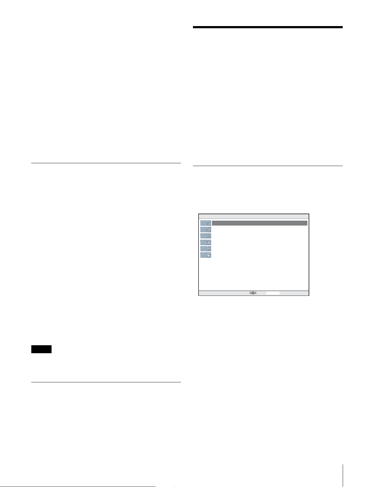
Activating the SYSTEM SETUP UTILITY
Select SYSTEM SETUP UTILI TY on the Main Screen to
activate it. The SYSTEM SETUP UTILITY display
appears.
3
Press the select R button (Memory Stick Format).
4
Select the format type: Full or Quick.
Normally press the select R button (Quick).
5
Press the select R button (YES).
Once “DONE” appears on the screen, formatting of the
Memory Stick is complete, and the MSSONY/PRO/UCP
folder is created.
Note
Formatting of the Memory Stick deletes all files stored in
the Memory Stick.
Soft Reset
Press the select L and R buttons simultaneously for more
than 3 seconds. A soft reset of the UCP-8060 is executed.
SYSTEM SETUP UTILITY Version 1.xx
Device Control
Adjust Time
Set TCP/IP Config
Calibrate Touch Panel
Scribble T est
Self Diagnosis
Exit 03:13:00
Select an item you wish to set.
For details on selecting an item, see “Basic Operations”
on page 34.
Functions of Each Menu Item
Device Control
Adjust each item with the following procedures:
1
Turn the jog roller to selec t a n item to be adjusted.
36
System Setup
2
Press the jog button to adjust the item.
3
Press the jog roller to register your adjusted value.
Page 37

4
Press the select R button when you are finished
making adjustments.
The adjusted values are stored.
To cancel an adjusted value, press the select L button.
• LCD Brightness
Adjust the brightness of the display window in sev en steps.
The default setting is “3”. You can adjust the brightness
referring to the Sample shown at the bottom of the screen.
• F-KEY LED Brightness
Adjust the brightness of the function buttons in seven
steps. The default setting is “5” (bright est). You can adjust
the brightness referring to the Sample shown at the bottom
of the screen.
Set TCP/IP Config.
The IP Address, Netmask, Gateway, and DNS have been
set at the factory, but you can change them as required.
1
Press the jog roller to select an item to be changed.
2
Press the jog L or R button to select the digit to be
changed.
3
Turn the jog roller to set the value.
4
Press the select R button when you are finished
settings.
The set v alues are stored.
5
Press the select R button to reflect the settings.
• Sound Control
Adjust the sound level of the touch-panel beep. The default
setting is “3.” When the sound level is changed, Sound
Test is executed.
• Sound Test
Displays “Now testing of sound” while the sound level is
adjusted with Sound Control.
• TouchEngine Force: ON/HIGH
Adjust the sensitivity of the TouchEngine in four levels,
OFF, ON/LOW, ON/MIDDLE, and ON/HIGH.
• Touch Beep Control
Enable/disable the touch-panel beep.
Adjust Time
Set the date and time. The set da te and time are ret ained in
memory for about 7 days even if the power is turned off.
1
Press the jog L or R button to select the dig it to be
adjusted.
2
Turn the jog roller to set th e value.
The system is rebooted.
To cancel the set values, press the select L button.
To retrieve the default se ttings, select Default.
Calibrating the Touc h Pan e l
Push the center of the crosshairs displayed in the four
corners on the touch p anel in orde r with a pen o r finger tip.
The relationship between the screen and touched position
is calibrated.
To calibrate from the beginning again, push some place
apart from the crosshairs on the touch panel until the
crosshairs appear in the upper-left corner. Then the
previous operation is canceled, and you can start the
calibration from th e beginning.
Scribble Test
You can check the operation status of the touch panel by
scribbling. Scribble on the screen with a pen, and the trace
will be shown.
Self Diagnosis
The operation of the jog roller, jog buttons, function
buttons, and control knobs can be checked.
3
Press the select R button when setting is completed.
The adjusted values are stored.
To cancel the adjustment, press the select L button.
System Setup
37
Page 38

Installation of the
For details on the IP address of the HTTP server and the
network connection, consult your network administrator.
Operation Software
The UCP-8060 is shipped with the operation software for
several products installed. If you wish to use another
product, install the operation software for the product
following the procedures below. It is also necessary to
install operation software when you update the system
files.
You can install the operation software using a Memory
Stick or via the Internet (HTTP server).
To obtain the operation software, consult your Sony
representative..
Note
The memory capacity to store the operation sof tware is
limited. You may remove some operation software when
you intend to install a new software.
For details on the capacity of a Memory Stick, see
“Checking the Information” on page 43.
For details on removing software, see “Removing the
Operation Software” on page 42.
Installation
Installing using a Memory Stick
1
Insert the Memory Stick in which the operation
software has been copied into the Memory Stick slot.
2
Press the select L button (Menu).
The Menu display appears.
3
Select Install Settings by turning the jo g roller, and
press the select R button (Enter).
The Install Settings display appears.
4
Select Memory Stick by turning the jog roller, and
press the select R button (Save).
The Menu display appears.
The procedures below depend on whether operation
software has been installed o r not.
If the operation software has been installed
Requirements
• Computer (t o enab le copying files to a Memory Stick if
a Memory Stick is to be used)
• Operation software to be installed (two file s, with the
extensions “jar” and “jad”)
Installation usi ng a M em ory Stick
• Memory Stick
Preparations
1
Copy the operation softwar e t o a Me mor y St i ck or t o
an HTTP server using a computer.
To copy onto a Memory St ick, prepare a folder named
MSSONY/PRO/UCP, and copy to a folder under
UCP.
When you format the Memory Stick on this machine ,
the MSSONY/PRO/UCP folder is automatically
created.
Note
If the filename or folder name has any non-ASCII
characters, installation may fail.
2
Turn the UCP-8060 on.
The Main Screen appears.
1
Select Install with the jog roller.
2
Press the select R button (Enter).
The Install display appears. Check that a file wit h the
extension “jad” in th e Memory Stick is display ed.
If the file name includes both upper- and lowercase
letters, installation is p erformed normally.
3
Select the operation software to be installed by
turning the jog roller, then press the select R button
(Go).
Information on the operation software appears.
4
If the displayed inform ation is correct, press the select
R button (Yes).
Installation begins. While reading and writing data,
the status indicator is lit o r blinking.
When installation is com pl e te , a me ssa ge to indicate
this appears on the screen.
Note
While reading and writing data, never turn the power
of the UCP-8060 off, or remove the installe d Memory
Stick. The file may be damaged.
38
Installation of the Operation Software
Page 39

5
Remove the Memory Stick.
6
Press the select R button (Restart).
It is recommended to set the URL ad dress he re. Then
you can skip entering the URL address e ach time you
install operation software afterwards.
The Main Screen appears. Check that the name of t he
installed operation software appears.
If the operation software has not been installed
1
Press the select L button (Back).
The Main Screen appears.
2
Press the select R button (Install).
The Install display appears. Check that the file with an
extension “jad” in th e Memory Stick is displayed.
3
Select the operation software to be installed by
turning the jog roller, then press the select R button
(Go).
Information on the operation software appears.
4
If the displayed inform ation is correct, press the select
R button (Yes).
Installation begins. While reading and writing data,
the status indicator is lit or blinking.
When installation is complete, a message to indicat e
this appears on the screen.
Note
While reading and writing data, never turn the power
of the UCP-8060 off, or remove the installed Memory
Stick. The file may be damaged.
5
Remove the Memory Stick.
For details on setting the URL address, see“Setting
the URL address” on page 40.
5
Press the select R button (Save).
The Menu display appears.
The procedures below depend on whether operation
software has been installed o r not.
If the operation software has been installed
1
Select Install by turn ing the jog roller.
2
Press the select R button (Enter).
The Install display appears.
3
Touch the keyboard icon on the task bar.
The keyboard appears on the screen.
4
Enter the URL address that contains the operation
software to be installed and the filename of the
operation software, then press the select R button
(OK).
Note
Be sure to enter the filename of the operat ion software
with the extension “jad.”
5
Press the select R button (Go).
Information on the operation software to be installed
appears.
6
Press the select R button (Restart).
The Main Screen appears. Check that the name of t he
installed operation software appears.
Installing using the Internet
1
Check that the UCP-8060 is connected to the Internet.
2
Press the select L button (Menu).
The Menu display appears.
3
Select Install Settin gs by turning the jog roller, then
press the select R button (Enter).
The Install Settings display appears.
4
Select Internet by turning the jog r oller.
6
If the displayed inform ation is correct, press the select
R button (Yes).
Installation begins. While reading and writing data,
the status indicator is lit o r blinking.
When installation is completed, a message to indicate
this appears on the screen.
Note
While reading and writing data, never turn the power
of the UCP-8060 off, or remove the installe d Memory
Stick. The file may be damaged.
7
Press the select R button (Restart).
The Main Screen appears. Check that the name of the
installed operation software appears.
Installation of the Operation Software
39
Page 40

If the operation software has not been installed
1
Press the select L button (Back).
The Main Screen appears.
2
Press the select R button (Install).
The Install display appears.
3
Touch the keyboard icon on the task bar.
The keyboard appears on the screen.
4
Enter the URL address for the operation software to
be installed, and the file name of the operation
software, then press the select R button (OK).
Note
Be sure to enter the filename of the operation software
with the extension “jad.”
5
Press the select R button (Go).
Information on the operation software to be installed
appears.
6
If the displayed inform ation is correct, press the select
R button (Yes).
Installation begins. While reading and writing data,
the status indicator is lit or blinking.
Updating the Operation Software
You can update the installe d operation software foll owing
the procedures below, and the upgraded operation
software can be used.
To obtain the operation software, consult your Sony
representative.
Note
The memory capacity to store the operation software is
limited. You may remove some operation software when
you intend to install new so ftwa re.
For details on removing software, see “Removing the
Operation Software” on page 42.
Requirements
• Computer (t o enable copying files to a Memory Stick if
a Memory Stick is to be used)
• Operation software to be installed (two files, with the
extensions “jar” and “jad”)
Updating the installed opera tion software usi ng a
Memory Stick
• Memory Stick
When installation is complete, a message to indicat e
this appears on the screen.
Note
While reading and writing data, never turn the power
of the UCP-8060 off, or remove the installed Memory
Stick. The file may be damaged.
7
Press the select R button (Restart).
The Main Screen appears. Check that the name of t he
installed operation software appears.
Setting the URL address
1
Select “http://” with th e jog roller, and push the jog
roller.
2
Touch the keyboard icon on the task bar.
The keyboard display appears on the screen.
3
Enter the URL address for the operation software to
be installed.
4
Press the select L button (OK).
Preparations
1
Copy the operation software to a Memory Stick or to
an HTTP server using a computer.
To copy onto a Memory St ick, prepare a folder named
MSSONY/PRO/UCP, then co py to a folder under
UCP.
When you format the Memory Stick on this machine ,
the MSSONY/PRO/UCP folder is automatically
created.
Note
If the filename or folder name has any non-ASCII
characters, installation may fail.
2
Turn the UCP-8060 on.
The Main Screen appears.
For details on the IP address of the HTTP server and the
network connection, consult your network administrator.
The Install Settings display appears.
40
Updating the Operation Software
Page 41

Updating
Updating using a Memory Stick
1
Insert the Memory Stick in which the operation
software has been copied into the Memory Stick slot.
2
Select the operation software to be updated on the
Main Screen.
3
Press the select L button (Menu).
The Menu display appears.
The Menu display appears.
4
Select Update by turning the jog roller, then press the
select R button (Enter).
The Update display appears. Check that the displayed
software is the version of th e operation softwar e to be
updated.
5
Press the select R button (Yes).
Information on the operation software appears.
6
If the displayed inform ation is correct, press the select
R button (Yes).
4
Select Update by turning the jog roller, then press the
select R button (Enter).
The Update display appears. Check that the displaye d
software is the version of the oper ation software t o be
updated.
5
Press the select R button (Yes).
Information on the operation software to be updated
appears.
6
If the displayed inform ation is correct, press the select
R button (Yes).
Updating begins. While r eading and wr iting da ta, the
status indicator is lit or blinking.
When updating is complete, a message to indicate this
appears on the screen.
Note
While the system is reading and writing data, nev e r
turn the power of the UCP-8060 off, or remove the
installed Memory Stick. The file may be damaged.
Updating begins. While the system is reading and
writing data, the status indicator is lit or blinking.
When update is complete, a message to indicate this
appears on the screen.
Note
While the system is reading and writing data, neve r
turn the power of the UCP-8060 off or remove the
installed Memory Stick. The file may be damaged.
7
Press the select R button (Restart).
The Main Screen appears.
Note
If the operation sof tware is protected, it can not be updat ed.
7
Remove the Memory Stick.
8
Press the select R button (Restart).
The Main Screen appears.
Note
If the operation software is protected, it cannot be updated.
Updating using the Internet
1
Check that the UCP-8060 is connected to the Internet.
2
Select the operation software to be updated on the
Main Screen.
3
Press the select L button (Menu).
Updating the Operation Software
41
Page 42

Removing the Ope r at io n
Protecting the Operation
Software
You can remove the operation software from the UCP8060 following the procedur e below. You cannot remove
the system setup utility.
1
Select the operation software to be removed on the
Main Screen.
2
Press the select L button (Menu).
The Menu display appears.
3
Select Remove by turning the jog roller, then press the
select R button (Enter).
The Remove display appears.
4
Press the select R button (Yes).
The confirmation message appears. Check that the
selected software is the version of the operation
software to be removed.
5
Press the select R button (Yes).
Software
If the operation software is protected, updating, deleting,
or installing of the operation software is prevented. You
can protect the operation software following the procedure
below.
1
Select the operation software to be protected on the
Main Screen.
2
Press the select L button (Menu).
The Menu display appears.
3
Select Info by turning the jog roller, then press the
select R button (Enter).
The Info display appears.
4
Press the select R button (Protect) to set the Prot ect to
On.
The protection is set.
5
Press the select L button (Back).
The selected operation software is removed. When
this is completed, the Main Screen appears.
The Main Screen appears.
Note
If the operation software is protected, it cannot be updated.
The Menu display appears.
6
Press the select L button (Back).
The Main Screen appears.
To cancel the pro tection
Set Protect to Off in step 4.
42
Removing the Operation So ftware / Protecting the Operation Software
Page 43

Checking the Informatio n
Updating System Files
You can check information about this unit following the
procedure below.
1
Press the select L button (Menu) on the Main Screen.
The Menu display appears.
2
Select About by turning the jog roller, then press the
select R button (Enter).
The About SONY AMS display appears.
Free Space
The space available for storing the operation software
is displayed in units of kilobytes.
Universal Control Panel Profile
The software version of the Universal Control Panel
Profile [UCPP] appears.
UNIQUE DEVICE ID
The ID unique to the device appears. Some software
functions may prompt you to input this ID.
For details, refer to the User’s Guide supplied with the
Operation Software.
The system files, which have been installed at the factory,
can be updated.
Note
If you update the system files, all operation software
installed in the UCP-80 60 is deleted. After updating,
reinstalling the operation software is required.
Requirements
• Computer (to enable copying files to a Memory Stick)
• Latest system files
• Operation software (for reinstallation after updating)
• Memory Stick
For details on obtaining the latest system files and
operation software, consult your Sony representative.
Checking the current version
It is recommended to check the current version of the
system before updating the system files.
For details on checking the version, see “Confirming of
the Basic Information” on page 35.
3
Press the select L button (Back).
The Menu display appears.
4
Press the select L button (Back).
The Main Screen appears.
Preparations
1
Format the Memory Stick using the format function
of the UCP-8060.
For details on formatting, see “Formatting a Memory
Stick” on page 36.
Note
If the file name or folder using the characters other
than ASCII code is included, installing may be failed.
2
Unzip the system files on the computer.
3
Copy the all unzipp ed data to t he fold er shown belo w
in the Memory Stick.
Example: If drive F is the Memory Stick, copy to F:/
MSSONY/PRO/UCP/.
Checking the Information / Updating System Files
43
Page 44

Updating
Updating requires about 15 minutes or more. Follow the
instructions on the screen.
Using a “Memory Stick”
Notes
• Never interrupt the installation.
• Never turn the power of the UCP-8060 off during
installing. The system files may be damaged.
1
Press the select L and R buttons while holding the
function 2 button pressed for more than 3 seconds
until the functi on 2 b utton lig hts. Once the f unc tion 2
button lights, release the buttons.
The UPDATE UTILITY starts.
You can start the UPDATE UTILITY from the
Shutdown display.
2
Insert the Memory Stick to wh ic h the system files
have been copied into the Memory Stick slot.
3
Press the select R button following the instruc tions on
the screen.
Updating begins.
When updating is complete, a message appears.
4
Remove the Memory Stick.
5
Press the select R button (Reboot).
The UCP-8060 is rebooted.
6
Once the operation software is updated, a calibration
display appears. Push the center of the crosshairs
using a pen.
The relationship between the screen and touch panel
is calibrated.
7
Re-install the operation software to be used.
For details on installing the operation software, see
“Installation of the Operation Software” on page 38.
About a “Memory Stick”
What is “Memory Stick”?
“Memory Stick” is a new compact, portable and versatile
IC (Integrated Circuit) recording medium with a data
capacity that exceeds a floppy disk.
“Memory Stick” is specially designed for exchan ging and
sharing digital data among “Memory Stick” compatibl e
products. Because it is removable, “Memory Stick” can
also be used for external data storage.
“Memory Stick” is available in two sizes: standard size
and compact “Memory Stick Duo” size. Once attached to
a Memory Stick Duo adapter, “Memory Stick Duo” turns
to the same size as standard “Memory Stick” and thus can
be used with products compliant with standard “Memory
Stick.”
Types of “Memory Stick”
“Memory Stick” is available in the following six types to
meet various requirements in functions.
• “Memory Stick-R”
Stored data are not overwritten. You can write data to
“Memory Stick-R” with “Memory Stick-R” compatible
products only. Copyright protected data that requires
MagicGate copyright protection technology cannot be
written to “Memory Stick-R.”
• “Memory Stick”
Stores any type of data except copyright-protected data
that requires the MagicGate copyright protection
technology.
• “MagicGate Memory Stick”
Equipped with the MagicGate copyright protection
technology.
• “Memory Stick-ROM”
Stores pre-recorded, read-only data. You cannot record on
“Memory Stick-ROM” or erase the pre-recorded data.
• “Memory Stick PRO”
Equipped with the MagicGate copyright protection
technology, designed for use only with equipment
compatible with “Memory Stick PRO.”.
44
Using a “Memory Stick”
• “Memory Stick” (with memory select function)
Equipped with the mult iple memories (128 MB). You can
select the memory to use with the memory selects switch
on the back of the “Memory St ick.” You cannot use
different memories simultaneously or continuously.
Page 45

Available types of “Memory St ick”
You can use various of “Memory Stick,” “Memory Stick
PRO” and “MagicGate Memory Sti ck” with your produc t.
However, because your product does not support the
MagicGate standards, data recorded with your product is
not subject to MagicGate copyright protection.
• Data may be damaged if:
– You remove the “Memory Stick” or turn off the unit
while it is reading or writing data.
– You use the “Memory Stick” in a location subject to
the effects of static electricity or electric noise.
• We recommend that you make a backup copy of
important data that you record on the “Memory Stick.”
Notes on “Memory Stick PRO”
You can use up to 1 GB “Memory Stick PRO ” with your
product.
Notes on “Memory Stick Duo”
• To use “ Memory Stic k Duo” with your product, attach it
to the Memory Stick Duo adapter before inserting it into
your product.
• Be sure to attach “Memory Stick Duo” to the adapter
with the correct orientation.
• Be sure to insert the Memory Stick Duo adapter with the
correct orientation. Otherwise, the product may be
damaged.
• Do not insert the Memory Stic k Duo adapter without
“Memory Stick Duo” attached. Doing so may result in
malfunction of the product.
Note on data read/write speed
Data read/write speed may vary depending on the
combination of the “Memory Stick” and “Memory Stick”
compliant product you use.
What is MagicGate?
MagicGate is copyright protection technology that uses
encryption technology.
Notes
• Do not attach anything other than the supplied label to
the “Memory Stick” labeling position.
• Attach the label so that it does not stick out beyond the
labeling position.
• Do not write forcefully on th e “Memory Stick Duo”
memo area.
• Carry and store the “Memory Stick” in its case.
• Do not touc h th e connect or of the “Memory Sti ck” with
anything, including your finger or metallic objects.
• Do not strike, bend, or drop the “Memory Stick.”
• Do not disassemble or modify the “Memory Stick.”
• Do not allow the “Memory Stick” to get wet.
• Do not use or store the “Memory Stick” in a location that
is:
– Extremely hot, such as in a car parked in the sun
– Under direct sunlight
– Very humid or subject to corrosive substances
About formatting “Memory Stick”
When “Memory Sticks” are shipped from the factory, they
are already formatted to a special standard. When you
format “Memory Stick,” we recommend formatting them
on this product.
Before using a “Memory Stick”
Terminal
Write-protect tab
Labeling position
• When you set th e “Memory Stick” erasure prevention
switch to “ LOCK,” data cannot be recorded, edit ed, or
erased.
• Position and shape of the write-protect tab may differ
depending on the “Memory Stick” to be used.
• Use a sharp object, such as a ballpoint pen, to move the
“Memory Stick Duo” erasure prevention switch.
Caution when formatting “Memory Stick”
on a personal computer
Pay attention on the following points when formatting
“Memory Stick” on a personal computer. Operation of
“Memory Stick” formatted on a personal computer is not
guaranteed on this product. To use a “Memory Sti ck” that
has been formatted on a personal computer, the “Memory
Stick” must be reformatted on this product. If it is not
reformatted, all data st ored on the “Memory Stic k” will be
lost.
For details on formatti ng a “Memory Stick ,” see
“Formatting a Memory Stick” on page 36.
Status Indicator
If the status indicator is turned on or is flashing, data is
being read from or written to the “Memory St ick.” At thi s
time, do not shake the co mputer or product or subject them
to shock. Do not turn off the power of the computer and
product or remove the “Memory Sti ck.” This may damage
the data.
Using a “Memory Stick”
45
Page 46

Precautions
• To prevent dat a loss, make backups of data frequent ly. In
no event will Sony be liable for any loss of data.
• Unauthorized recording may be contrary to the
provisions of copyrigh t law.
• The “Memory Stick” application software may be
modified or changed by Sony without prior notice.
“Memory Stick Duo” and are the
trademarks of So ny Corporation.
“Memory Stick” and are the trademarks of So ny C orporation.
“MagicGate Memory Sti ck” and are the
trademarks of So ny Corporation.
“Memory Stick-RO M ” and are the
trademarks of Sony Corpora tion.
“Memory Stick PRO” and are the
trademarks of Sony Corpora tion.
“Memory Stick R” and are the trademarks
of Sony Corporation.
Maintenance
Clean the display window with a soft cloth lightly
moistened with ethanol. Be sure to wipe lightly just the dirt
places. Moistening the cloth with too much ethanol or
wiping the screen may result in spreading the dirt.
A lens cleaning cloth may be usef ul to clean the screen.
Notes
• Do not use liquid other than ethanol to clean the scr een.
• Be careful no t to drip ethanol bet ween the screen and the
body while cleaning.
• Wiping the screen with excessive force may scratch th e
surface.
46
Maintenance
Page 47

Specifications
Main unit
Input/output signal s
DATA LAN: conforming to 100BASE-TX
RS-232C: conforming to RS-232C
EXT PANEL1: conforming to the RS-485
EXT PANEL2: conforming to the RS-485, with the
power supply pin
Power requirements
100 to 240 V AC, 50/60 Hz
Current consumption
100 V AC: 0.31 A
240 V AC: 0.19 A
Power cons umption
Max. 46 W
Peak inrush current
(1) Power ON, current probe method:
58 A (240 V), 23 A (100 A)
(2) Hot switching inrush current, measured in
accordance with European standard EN55103-1:
9 A (230 V)
Operating temperature
5°C to 40°C (32°F to 10°F)
Performance guaranteed temperature
10°C to 35°C (50°F to 95°F)
Storage temperature
–20°C to +60°C (–4°F to +140°F)
Humidity 10% to 90% RH
Dimensions (w/h/d)
306 × 65.3 × 132 mm
1
(12
/8 × 2 5/8 × 5 1/4 inches)
Mass 1.6 kg (3 lb 8 oz)
Accessories supplied
Rack mount bracket (1 set)
Operation Manual (1)
Installation Manual (1)
Optional accessories
Maintenance Manual
Key top puller 3-179-054-01
AC power cord U.S.A. and Canada: 1-557-377-11
(125 V, 10 A, 2.4 m)
Europe: 1-782-929-11 (250 V, 10 A,
2.5 m)
Design and specifications are subject to change without
notice.
Specifications
47
Page 48

Page 49

このマニュアルに記載されている事柄の著作権は当社にあり、説
明内容は機器購入者の使用を目的としています。
従って、当社の許可なしに無断で複写したり、説明内容 ( 操作、保
守等 ) と異なる目的で本マニュアルを使用することを禁止します。
The material conta ined in this manual consis ts of informa tion
that is the property of Sony Corporation and is intended
solely for use by the purc has ers of the equipment described
in this manual.
Sony Corporation expressly prohibits the duplication of any
portion of this manual or the use thereo f for any purpose
other than the operation or maintenance of the equipment
described in this manual witho ut the ex pres s written
permission of Sony Corp oration.
Page 50

UCP-8060 (SY)
3-704-876-02(1)
Sony Corporation
B&P Company
Printedonre cycledpaper
Printed in Japan
2003.5.13
© 2002
 Loading...