

Sony Trinitron PVM-D14L5A, Trinitron PVM-D20L5A Operating Instructions Manual
4-089-510-12 (1)
Trinitr on
®
Color Video Monitor
Operating Instructions
Before operating the unit, please read this manual
thoroughly and retain it for future reference.
FR
PVM-D14L5A
PVM-D20L5A
2002 Sony Corporation

Owner’ s Recor d
The model and serial numbers are located at the rear.
Record these numbers in the spaces provided below.
Refer to these numbers whenever you call upon your
Sony dealer regarding this product.
Model No.
Serial No.
WARNING
To prevent fire or shock hazard, do not
expose the unit to rain or moisture.
Dangerously high voltage are present
inside the unit.
Do not open the cabinet. Refer servicing
to qualified personnel only.
In the event of a malfunction or when maintenance is
necessary, consult an authorized Sony dealer.
ATTENTION – When the product is installed in
a rack:
a) Elevated operating ambient temperature
If installed in a closed or multi-unit rack assembly,
the operating ambient temperature of the rack
environment may be greater than room ambient.
Therefore, consideration should be given to
installing the equipment in an environment
compatible with the manufacture’s maximum rated
ambient temperature (Tmra: 0°C to 35°C (32°F to
95°F)).
e) Reliable earthing
Reliable earthing of rack-mounted equipment
should be maintained. Particular attention should
be given to supply connections other than direct
connections to the branch circuit (e.g., use of power
strips).
f) Gap keeping
Upper and lower gap of rack-mounted equipment
should be kept 44 mm (1 3/4 inches).
b) Reduced air flow
Installation of the equipment in a rack should be
such that the amount of air flow required for safe
operation of the equipment is not compromised.
c) Mechanical loading
Mounting of the equipment in the rack should be
such that a hazardous condition is not achieved
due to uneven mechanical loading.
d) Circuit overloading
Consideration should be given to the connection of
the equipment to the supply circuit and the effect
that overloading of circuits might have on
overcurrent protection and supply wiring.
Appropriate consideration of equipment nameplate
ratings should be used when addressing this
concern.
2

Precaution
On safety
•Operate the unit only with a power source as
specified in “Specifications” section.
• The nameplate indicating operating voltage, power
consumption, etc., is located at the rear.
• Should any solid object or liquid fall into the cabinet,
unplug the unit and have it checked by qualified
personnel before operating it any further.
•Do not drop or place heavy objects on the power
cord. If the power cord is damaged, turn off the
power immediately. It is dangerous to use the unit
with a damaged power cord.
•Unplug the unit from the wall outlet if it is not to be
used for several days or more.
•Disconnect the power cord from the AC outlet by
grasping the plug, not by pulling the cord.
• The socket-outlet shall be installed near the
equipment and shall be easily accessible.
On installation
On cleaning
To keep the unit looking brand-new, periodically clean
it with a mild detergent solution. Never use strong
solvents such as thinner or benzine, or abrasive
cleansers since they will damage the cabinet. As a
safety precaution, unplug the unit before cleaning it.
On repacking
Do not throw away the carton and packing materials.
They make an ideal container which to transport the
unit. When shipping the unit to another location,
repack it as illustrated on the carton.
If you have any questions about this unit, contact your
authorized Sony dealer.
English
•Allow adequate air circulation to prevent internal
heat build-up.
Do not place the unit on surfaces (rugs, blankets,
etc.) or near materials (curtains, draperies) that may
block the ventilation holes.
•Do not install the unit in a location near heat sources
such as radiators or air ducts, or in a place subject to
direct sunlight, excessive dust, mechanical vibration
or shock.
On cleaning of the CRT surface
• The surface of the CRT has an optional PET film
treatment.
Clean the CRT surface using the following method
to avoid damaging the surface.
•Clean the CRT with a soft cloth.
When the CRT is dirtied with oily hands or
fingerprints, clean it with a soft cloth moistened with
a mild detergent solution.
•Never use abrasive cleansers, alkaline soap, strong
solvents such as alcohol, thinner or benzine, since
they will damage the surface.
•Do not rub the surface of the CRT with a solid object
or hit it.
3

Table of contents
Precaution .......................................................................... 3
Features.............................................................................. 5
Connections....................................................................... 7
How to Connect the AC Power Cord......................................7
How to Connect a Cable to a BNC Connector........................7
Location and Function of Parts and Controls ................ 8
Control Panels .........................................................................8
Rear Panel .............................................................................10
Selecting the Menu Language........................................ 13
Using the Menu................................................................ 14
Display List ...................................................................... 15
STATUS Menu.................................................................. 17
COLOR TEMP/BAL Menu................................................ 17
USER CONTROL 1/2, 2/2 Menu ...................................... 18
USER CONFIG 1/2, 2/2 Menu .......................................... 19
REMOTE 1/2 PARALLEL Menu....................................... 20
REMOTE 2/2 SERIAL Menu............................................. 20
OPTION CONFIG Menu ................................................... 21
KEY PROTECT Menu....................................................... 22
Troubleshooting .............................................................. 22
Specifications .................................................................. 23
The explanation given in this manual can be applied to the
following models unless noted otherwise.
When explanation differs among models, this is clearly
indicated in this manual.
•PVM-D14L5A (14-inch monitor)
•PVM-D20L5A (20-inch monitor)
Illustrations of the video monitor are of the PVM-D14L5A.
4
Features
The PVM-D14L5A/PVM-D20L5A is a Trinitron color
video monitor for professional use.
Picture
HR (High Resolution) Trinitron1) picture tube
HR Trinitron tube provides a high resolution picture.
Horizontal resolution is more than 800 TV lines at the
center of the picture.
Comb filter
When NTSC video signals are received, a comb filter
activates to make more accurate Y/C separation. This
contributes to less of a decrease in resolution, cross
color and cross luminance phenomena.
Beam current feedback circuit
The built-in beam current feedback circuit assures
stable white balance.
Two color system available
The monitor can display NTSC and PAL signals. The
appropriate color system is selected automatically.
Auto chroma phase function
The chroma and phase of the decoder are
automatically adjusted with the auto chroma phase
function.
Blue only mode
In the blue only mode, an apparent monochrome
display is obtained with all three of the R/G/B
cathodes driven with a blue signal. This facilitates
color saturation and phase adjustments and observation
of VCR noise.
Input
Y/C input connectors (S-input connector)
The video signal, split into the luminance signal (Y)
and the chrominance signal (C), can be input through
this connector, eliminating the interference between
the two signals, which tends to occur in a composite
video signal, ensuring video quality.
Expandable input capability
You can easily expand the input capability by
installing an input adaptor (not supplied) in the input
option slot in the rear of the monitor.
External sync input
When the EXT SYNC selector is in the on position,
the monitor can be operated on the sync signal
supplied from an external sync generator.
Automatic termination (connector with
mark only)
The input connector is terminated at 75 ohms inside
when nothing has been connected to the output
connector. If a cable is connected to the output
connector, the internal terminal is automatically
released and the signals input to the input connector
are output to the output connector (loop-through).
Functions
Multiformat
The monitor supports the principal formats (480I/
480P/720P/1080I) for digital broadcasts as well as
conventional NTSC and PAL color systems — a wide
variety of signals whose horizontal frequency is
between 15 kHz and 45 kHz.
Underscan mode
The signal normally scanned outside of the screen can
be monitored in the underscan mode.
Analog RGB/component input connectors
Analog RGB or component (Y, R-Y and B-Y) signals
from video equipment can be input through these
connectors. Select either of two signals using the RGB/
COMP input switch button.
.........................................................................................................................................................................................................
1) “Trinitron” is a registered trademark of Sony Corporation.
Note
When the monitor is in the underscan mode, the dark
RGB scanning lines may appear on the top edge of the
screen. These are caused by an internal test signal,
rather than the input signal.
Horizontal/vertical delay mode
The horizontal and vertical sync signals can be
monitored simultaneously in the H/V delay mode.
5

Features
Internal Caption Vision (Closed Caption)
Decoder
When the image signals with caption vision signals are
input, the English subtitles are superimposed and
displayed on the screen. You can select the caption
ON/OFF and the caption type in the menu.
Auto/manual degaussing
The CRT is automatically degaussed when the power
is turned on. You can manually degauss the CRT by
pressing the DEGAUSS button.
In the menu, you can set the time to automatically
degauss after turning on the power.
Note
The DEGAUSS button is disabled when the screen
menu is being displayed.
To manually degauss the CRT, exit the screen menu
by pressing the MENU button.
On-screen menus
You can set color temperature, CHROMA set up, and
other settings by using the on-screen menus.
EIA 19-inch rack mount bracket available
The monitor may be mounted on an EIA-standard 19inch rack, using an optional mounting bracket MB-521
or slide rail SLR-104 (for PVM-D14L5A and PVMD20L5A).
For details on mounting the monitor on the rack, refer to the
Operating Instructions of the mounting bracket or slide rail.
6
Connections
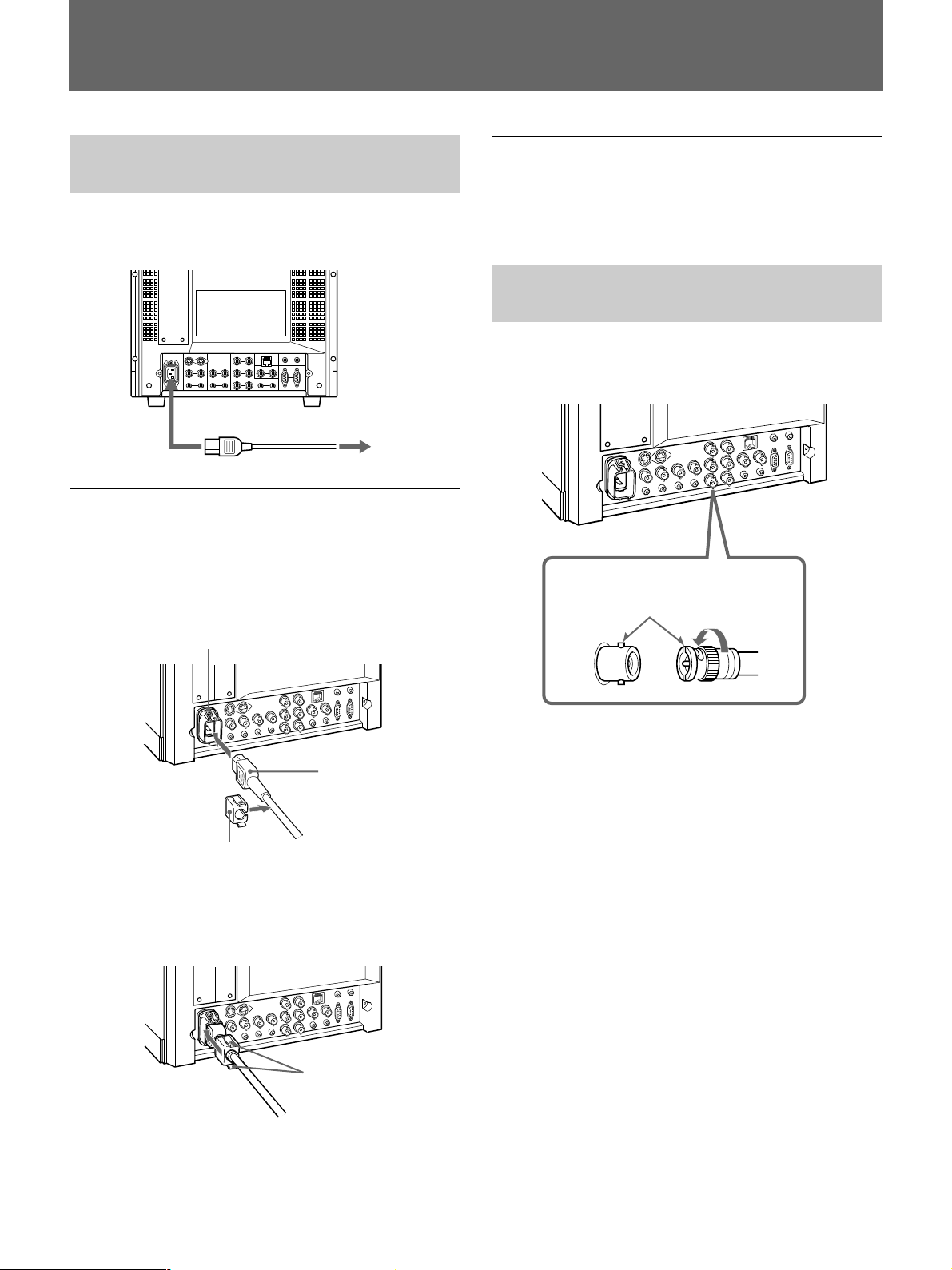
How to Connect the AC Power Cord
Connect the AC power cord (supplied) to the AC IN
socket on the rear panel and to a wall outlet.
to AC IN
to a wall outlet
To connect an AC power cord securely
with AC plug holder
1 Plug the power cord into the AC IN socket. Then,
attach the AC plug holder (supplied) on top of the
AC power cord.
To remove the AC power cord
Pull out the AC plug holder while pressing the lock
levers.
How to Connect a Cable to a BNC Connector
Connect a coaxial cable with the BNC plugs to the
BNC connectors on the rear panel as illustrated below.
Insert the BNC plug into the connector on
the rear panel, matching the slit and pin,
and turn the BNC plug clockwise to
secure the connection.
AC IN socket
AC power plug
AC plug holder
2 Slide the AC plug holder over the cord until it
locks.
Lock levers
7
Location and Function of Parts and Controls
Location and Function of Parts and Controls
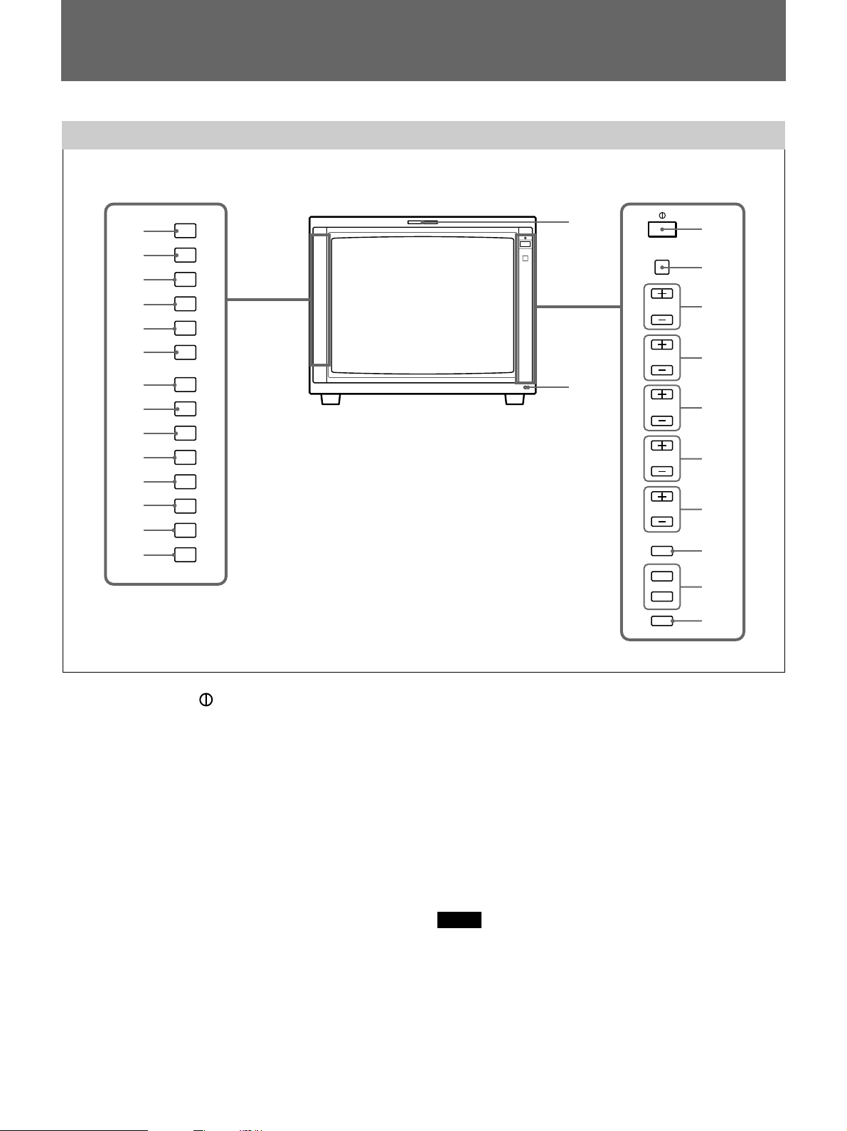
Control Panels
qd
qf
qg
qh
qj
qk
ql
w;
wa
ws
wd
wf
wg
wh
LINE
A
LINE
B
RGB/
COMP
OPTION
A
OPTION
B
EXT
SYNC
UNDER
SCAN
16:9
BLUE
ONLY
MONO
H/V
DELAY
4:3
MARKER
DEGAUSS
RESET
qa
qs
CONTROL
VOLUME
CONTRAST
PHASE
CHROMA
BRIGHT
MENU
UP
DOWN
ENTER
1
2
3
4
5
6
7
8
9
0
1 POWER switch ( )
Press the switch to turn on the power. The operation
buttons on both sides of the unit turn on. Press the
switch again to turn off the power.
2 CONTROL button
Press this button to turn on and enables the operation
button. Press this button again to turn off and disables
the operation buttons.
You can adjust the brightness of the operation buttons by
using the UP or DOWN buttons.
3 VOLUME control button
Press the + button to increase the volume or – button
to decrease the volume.
4 CONTRAST control button
Press the + button to make the contrast higher or the –
button to make it lower.
8
5 PHASE control button
Press the + button to make the complexion greenish or
the – button to make it purplish.
6 CHROMA control button
Press the + button to increase the color intensity or the
– button to decrease it.
7 BRIGHT (brightness) control button
Press the + button to increase the brightness or the –
button to decrease it.
Notes
•The PHASE (5) and CHROMA (6) control buttons
have no effect on the pictures of RGB signals.
•The PHASE (5) control button has no effect on the
PAL signals and pictures of component signals.
8 MENU button
Press this button to display or exit the main menu.

9 UP button
Down button
Use these buttons to select an item from a menu or
adjust the values. If the menu is not displayed, you can
use these buttons to adjust the brightness for the control
panels. You can adjust the brightness at 5 levels.
0 ENTER button
Press the button to confirm a selected item on the
menu.
qa Tally lamp
Lights up when the video camera connected to this
monitor is selected, indicating that the picture is being
recorded.
For details on how to light the tally lamp, see page 25.
qs POWER indicator
Press the POWER switch, the indicator will light
green.
qd LINE A (INPUT A) select button
Press this button to monitor the signal through the
LINE A connector.
qf LINE B (INPUT B) select button
Press this button to monitor the signal through the
LINE B connector.
qg RGB/COMP select button
Press this button to monitor the signal through the
RGB/COMPONENT connectors.
You can set the RGB/COMPONENT in the menu
screen. For details, see page 19.
ql UNDER SCAN button
Press this button (light on) for underscanning.
The display size is reduced by approximately 5% so
that four corners of the raster are visible.
w; 16:9 button
Press this button to monitor the signals of 16:9 picture.
Note
The aspect ratio is fixed to 16:9 when the signal other
than 4:3 signal format is input.
wa BLUE ONLY button
Press this button to eliminate the red and green signals.
Only blue signal is displayed as an apparent
monochrome picture on the screen. This facilitates
“chroma” and “phase” adjustments and observation of
VCR noise.
ws MONO button
Press this button to display a monochrome picture.
When the buttons is pressed again, the monitor
switches automatically to color mode.
wd H/V DELAY button
Press this button to observe the horizontal and vertical
sync signals at the same time.
The horizontal sync signal is displayed in the left
quarter of the screen; the vertical sync signal is
displayed near the center of the screen.
wf 4:3 MARKER button
When this button is pressed, a 4:3 marker is displayed
and it is possible to check the 4:3 aspect area.
qh OPTION A button
This button is used if an option board has been
installed in the option slot in the monitor’s rear. Press
this button to monitor the image/audio signals from the
option board input 1.
qj OPTION B button
This button is used if an option board has been
installed in the option slot in the monitor’s rear. Press
this button to monitor the image/audio signals from the
option board input 2.
(This button is disabled if BKM-129X or BKM155DV is used.)
qk EXT SYNC (external sync) button
Press this button to operate the monitor on an external
sync signal through the EXT SYNC IN connector.
Note
The 4:3 marker is not displayed when the signals of
the 4:3 aspect ratio are monitored or the monitor is in
H/V delay mode
wg DEGAUSS button
Press this button momentarily. The screen will be
demagnetized. Wait for 10 minutes or more before
using this button again.
wh RESET button
Pressing this button while changing the menu setting
resets the menu to the previous setting. Pressing this
button while changing VOLUME, PHASE, CHROMA
or BRIGHT resets the respective setting to the default.
9
 Loading...