

Sony Trinitron PVM-9045QM, Trinitron PVM-9042QM, Trinitron PVM-9040ME Operating Instructions Manual
3-865-058-22 (1)
Trinitr on
®
Color Video Monitor
Operating Instructions
Mode d’emploi
Bedienungsanleitung
Manual de instrucciones
Istruzioni per l’uso
XXXXX
GB
FR
DE
ES
IT
CS
PVM-9045QM PVM-9042QM
PVM-9040ME
1998 Sony Corporation
1 (EN)

English
WARNING
To prevent fire or shock hazard, do not
expose the unit to rain or moisture.
Dangerously high voltages are present inside
the unit. Do not open the cabinet. Refer
servicing to qualified personnel only.
In the event of a malfunction or when
maintenance is necessary, consult an authorized
Sony dealer.
THIS APPARATUS MUST BE EARTHED
For the customers in the UNITED KINGDOM
IMPORTANT
The wires in this mains lead are coloured in accordance with
the following code:
Green-and-yellow : Earth
Blue : Neutral
Brown : Live
As the colours of the wires in the mains lead of this
apparatus may not correspond with the coloured markings
identifying the terminals in your plug proceed as follows:
The wire which is coloured green-and-yellow must be
connected to the terminal in the plug which is marked with
the letter E or by the safety earth symbol Y or coloured
green or green-and-yellow.
The wire which is coloured blue must be connected to the
terminal which is marked with the letter N or coloured black.
The wire which is coloured brown must be connected to the
terminal which is marked with the letter L or coloured red.
CAUTION:
Danger of explosion if battery is incorrectly replaced.
Replace only with the same or equivalent type recommended
by the manufacturer. Discard used batteries according to the
manufacturer’s instructions.
Voor de klanten in Nederland
Bij dit produkt zijn batterijen geleverd.
Wanneer deze leeg zijn, moet u ze niet
weggooien maar inleveren als KCA.
For the customers in Europe
This product with the CE marking complies with both the
EMC Directive (89/336/EEC) and the Low Voltage Directive
(73/23/EEC) issued by the Commission of the European
Community.
Compliance with these directives implies conformity to the
following European standards:
• EN60950: Product Safety
• EN55103-1: Electromagnetic Interference (Emission)
• EN55103-2: Electromagnetic Susceptibility (Immunity)
This product is intended for use in the following
Electromagnetic Environment(s):
E1 (residential), E2 (commercial and light industrial), E3
(urban outdoors) and E4 (controlled EMC environment, ex.
TV studio).
Ensure that your equipment is connected
correctly.
If you are in any doubt consult a qualified
electrician.
2 (GB)

Precautions
On safety
•PVM-9045QM/9042QM: Operate the unit on 100 -
240 V AC or 12 V DC. For the AC operation, use
only the supplied AC power cord or the AC power
adaptor recommended (not supplied). Do not use any
other type.
For the battery operation, use only the NP-1B battery
pack and BP-L60A/L90A with DC-L10 (not
supplied). Do not use any other batteries.
•PVM-9040ME: Operate the unit only on 100 - 240 V
AC. Use only the supplied AC power cord. Do not
use any other type.
•Should any liquid or solid object fall into the cabinet,
unplug the unit and have it checked by qualified
personnel before operating it further.
•Unplug the unit from the wall outlet if it is not to be
used for several days.
•To disconnect the AC power cord, pull it out by the
plug. Never pull the cord itself.
On installation
ATTENTION – When the product is
installed in a rack:
a) Elevated operating ambient temperature
If installed in a closed or multi-unit rack assembly,
the operating ambient temperature of the rack
environment may be greater than room ambient.
Therefore, consideration should be given to
installing the equipment in an environment
compatible with the manufacturer’s maximum rated
ambient temperature of 0 to +35°C (32 to 95°F )
(Tmra).
b) Reduced air flow
Installation of the equipment in a rack should be
such that the amount of air flow required for safe
operation of the equipment is not compromised.
c) Mechanical loading
Mounting of the equipment in the rack should be
such that a hazardous condition is not achieved due
to uneven mechanical loading.
GB
English
•Allow adequate air circulation to prevent internal heat
build-up. Do not place the unit on surfaces (rugs,
blankets, etc.) or near materials (curtains, draperies)
that may block the ventilation holes.
•Do not install the unit near heat sources such as
radiators or air ducts, or in a place subject to direct
sunlight, excessive dust, mechanical vibration or
shock.
•Keep the unit away from a loudspeaker or motor, as
the picture may be affected.
On cleaning
Clean the unit with a slightly dampened soft cloth. Use
a mild household detergent. Never use strong solvents
such as thinner or benzine as they might damage the
finish of the cabinet.
As a safety precaution, unplug the unit before cleaning
it.
On repacking
d) Circuit overloading
Consideration should be given to the connection of
the equipment to the supply circuit and the effect
that overloading of circuits might have on
overcurrent protection and supply wiring.
Appropriate consideration of equipment nameplate
ratings should be used when addressing this
concern.
e) Reliable earthing
Reliable earthing of rack-mounted equipment
should be maintained. Particular attention should be
given to supply connections other than direct
connections to the branch circuit (e.g., use of power
strips).
f) Gap keeping
The upper and lower gaps of rack-mounted
equipment should be least 44 mm (1
3
/4 inches).
Retain the original carton and packing materials for
safe transport of this unit in the future.
If you have any questions about this unit, contact your
authorized Sony dealer.
3 (GB)
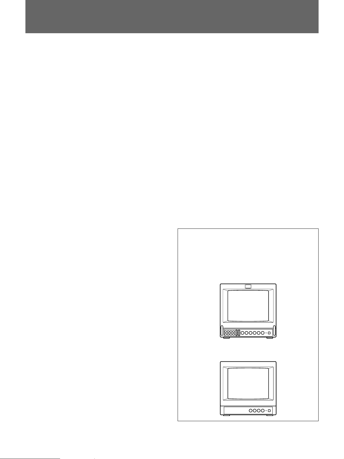
Table of Contents
Features.............................................................................. 5
Location and function
of parts and controls .................................................... 6
Front...................................................................................6
Rear ....................................................................................8
Power sources ................................................................. 10
Specifications .................................................................. 11
This instruction manual covers the PVM-9045QM,
PVM-9042QM and PVM-9040ME.
The differences among the models are clearly
described in the text.
PVM-9045QM/9042QM
PVM-9040ME
4 (GB)

Features
Four colour systems available
(PVM-9045QM/9042QM only)
The monitor can display PAL, SECAM, NTSC and
1)
4.43
NTSC
signals. The appropriate colour system is
selected automatically.
® 2)
HR (High Resolution) Trinitron
picture tube
(PVM-9045QM)
The HR Trinitron picture tube (0.25 mm aperture grill
pitch) provides a high resolution picture. Horizontal
resolution is more than 450 TV lines at the center of
the picture.
Trinitron picture tube (PVM-9042QM/9040ME)
The Trinitron picture tube (0.5mm aperture grill pitch)
provides a high resolution picture. Horizontal
resolution is more than 250 TV lines at the center of
the picture.
Beam current feedback circuit
The built-in beam current feedback circuit assures
stable white balance.
Multiple input signals
(PVM-9045QM/9042QM only)
In addition to the composite video signals and the Y/C
signals, analog RGB signals and component signals
can be input.
External sync input
(PVM-9045QM/9042QM only)
When the EXT SYNC button is pressed, the monitor
can be operated on the sync signal fed through an
external sync connector.
Blue only picture (PVM-9045QM/9042QM only)
Black and white apparent picture consisting from only
the blue signal will be displayed. This facilitates the
chroma adjustment, and the observation of the video
noise.
16:9 selector (PVM-9045QM/9042QM only)
The monitor can display the 16:9 signal with the
correct ratio of width and height, compressing the
picture vertically.
Under scan mode (PVM-9045QM/9042QM only)
The monitor can display signals that are scanned
outside the normal screen so you can monitor the
whole image.
Audio circuit and built-in speaker
A speaker (0.5 W, monaural) is built into the monitor
for sound monitoring.
Automatic/Manual DEGAUSS
The screen is automatically demagnetized when the
monitor is turned on. Manual degauss is also available
for PVM-9045QM/9042QM by pressing the
DEGAUSS button.
Automatic termination
(only connectors marked
)
The Y/C, VIDEO IN and EXT SYNC IN connectors
are terminated at 75 ohms inside, when no cable is
connected to the loop-through output connectors.
When a cable is connected to an output connector, the
75-ohm termination is automatically released.
EIA standard 19-inch rack mounting
By using an MB-520 mounting bracket (not supplied),
the monitor can be mounted in an EIA standard 19inch rack. For details on mounting, see the instruction
manual of the MB-520.
Varied power sources
In addition to AC power, you can use battery pack or
external DC 12 V power. The monitor can operate with
one or two Sony NP-1B* battery packs. If you use the
DC-L10* battery adaptor, the monitor can operate with
a Sony BP-L60A/L90A* lithium ion battery pack.
* The NP-1B battery pack, DC-L10 battery adaptor
and BP-L60A/L90A battery pack are not supplied.
..........................................................................................................................................................................................................
1) An NTSC 4.43 signal is used for playing back NTSC-recorded video cassettes with a video tape recorder/player especially
designed for use with this system.
2) Trinitron is a trademark of Sony Corporation.
5 (GB)
Location and Function of Parts and Controls
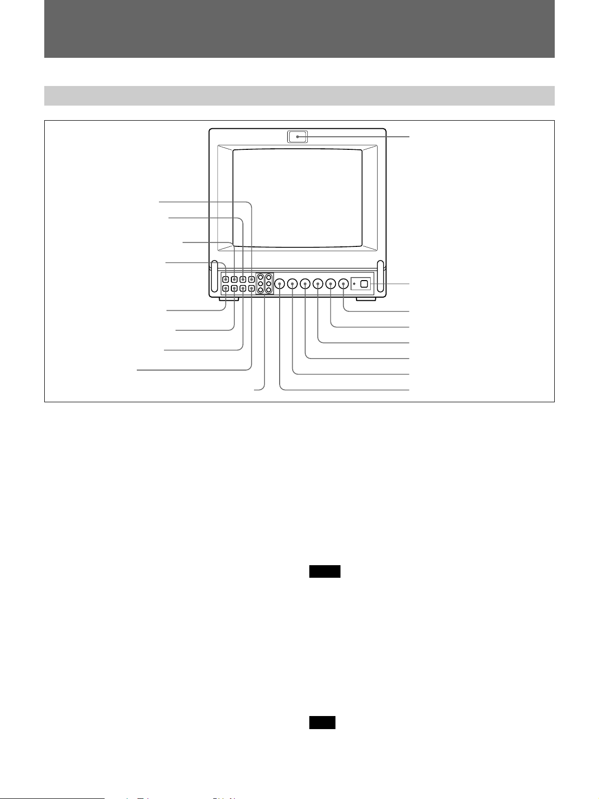
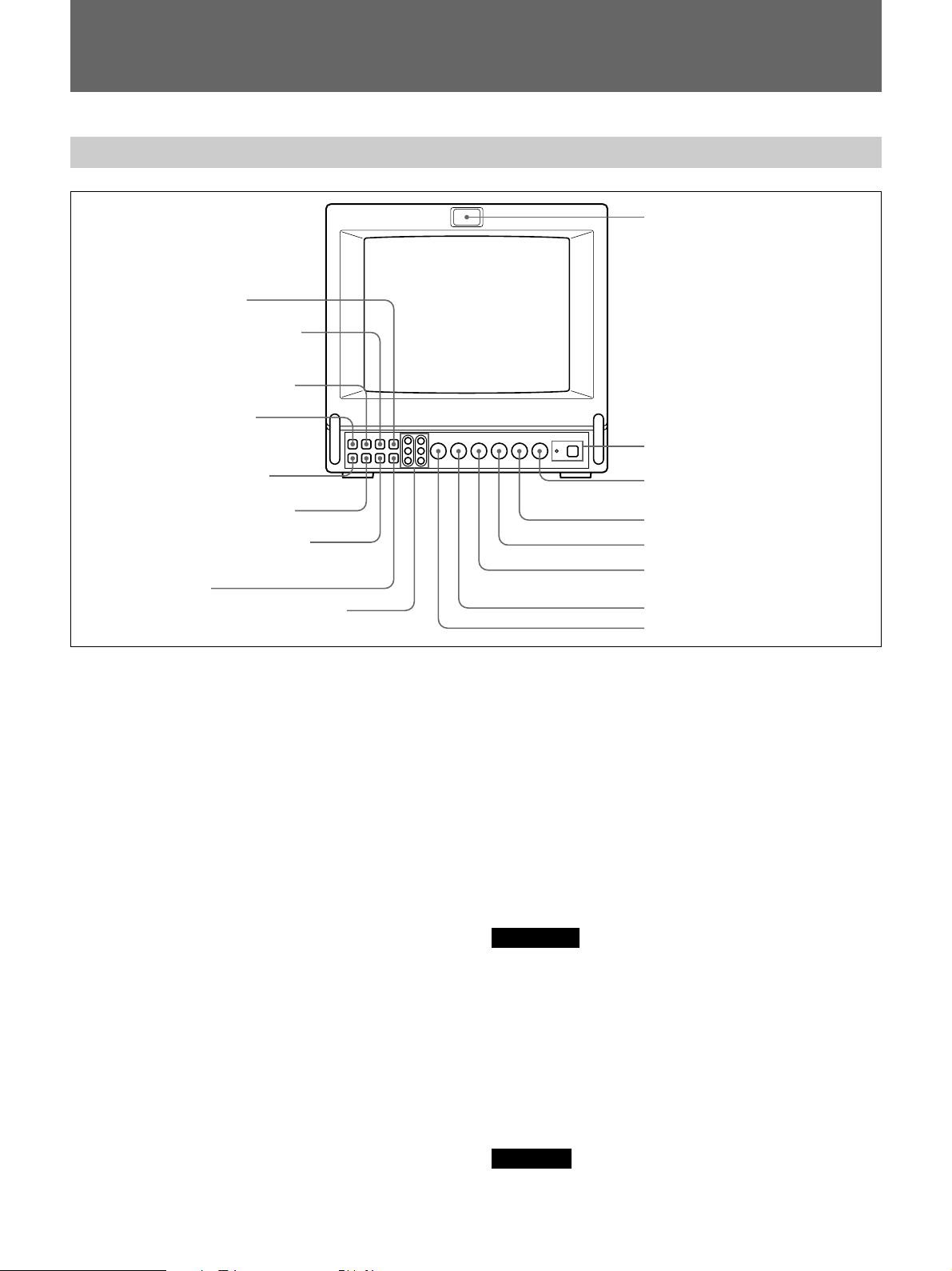
Front
PVM-9045QM/9042QM
9 DEGAUSS button
!º SYNC INT/EXT (sync
internal/external) selector
!¡ LINE/RGB input selector
!™ A/B, RGB/Y R-Y B-Y
input selector
!£ BLUE ONLY selector
!¢ UNDER SCAN selector
!∞ H/V DELAY selector
!§ 16:9 selector
!¶ R/G/B BIAS and GAIN adjustment controls
1 Tally lamp
This indicator lights up. The tally control connection is
needed.
For the pin assignment, see “Specificatons” on page
12 (GB).
2 POWER switch and indicator
Depress to turn the monitor on. The indicator will light
up in green.
The POWER indicator also functions as the battery
indicator. When the internal battery becomes weak or
the power supplied through the DC 12 V IN jack
decreases, the indicator flashes.
3 VOLUME control
Turn this control clockwise or counterclockwise to
obtain the desired volume.
4 CONTR (contrast) control
Turn clockwise to make the contrast stronger and
counterclockwise to make it weaker.
5 PHASE control
This control is effective only for the NTSC and
NTSC
4.43 colour systems. Turn clockwise to make the
skin tones greenish and counterclockwise to make
them purplish.
1 Tally lamp
2 POWER switch and indicator
3 VOLUME control
4 CONTR (contrast) control
5 PHASE control
6 CHROMA control
7 BRIGHT (brightness) control
8 APER (aperture) control
6 CHROMA control
Turn clockwise to make the colour intensity stronger
and counterclockwise to make it weaker.
7 BRIGHT (brightness) control
Turn clockwise for more brightness and
counterclockwise for less.
8 APER (aperture) control
Turn clockwise for more sharpness and
counterclockwise for less.
Notes
•The PHASE, CHROMA and APER control settings
have no effect on an analog RGB signal.
•The PHASE control has no effect on component
signals.
•The PHASE control setting is effective only for the
NTSC system.
9 DEGAUSS button
Press this button momentarily. The screen will be
demagnetized.
Note
If you press the DEGAUSS button again too soon, the
color shades may be uneven.
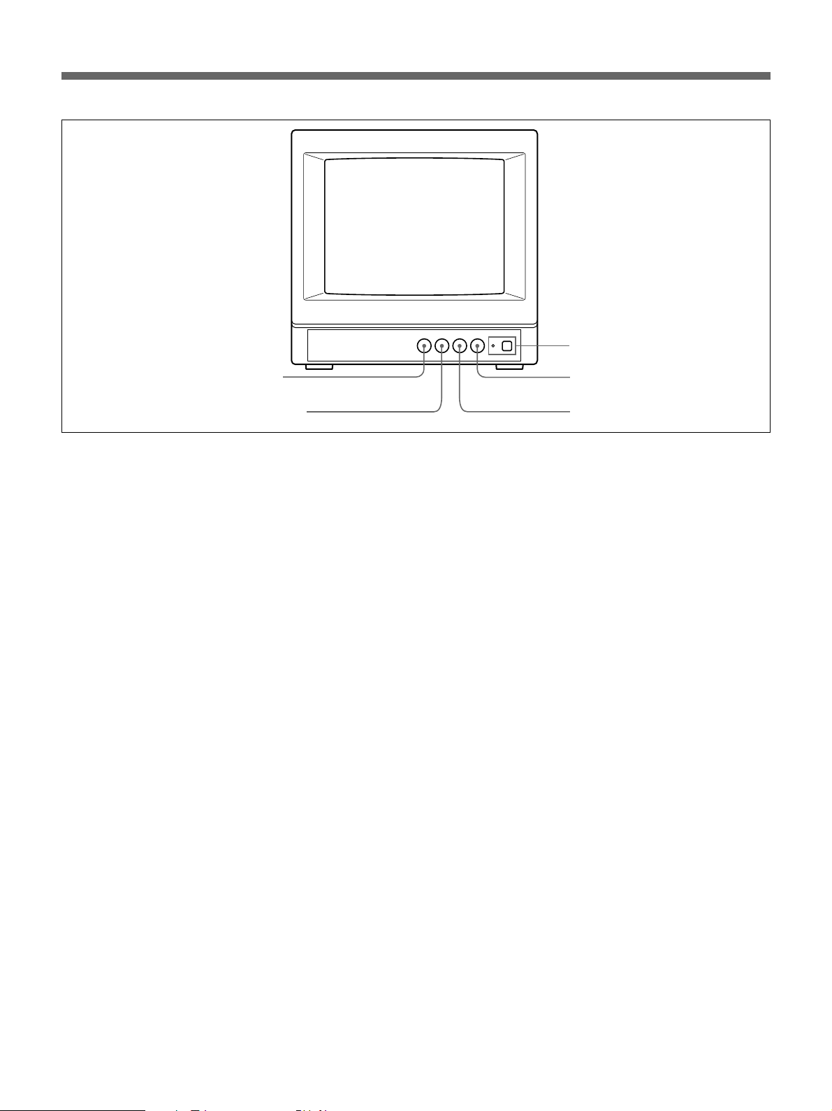
6 (GB)
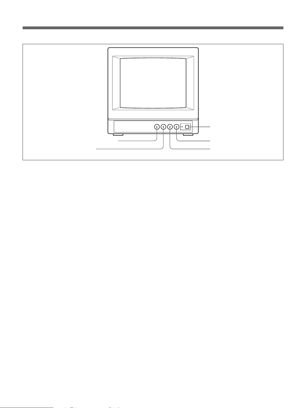
PVM-9040ME
2 POWER switch and indicator
7 BRIGHT (brightness) control
6 CHROMA control
!º SYNC INT/EXT (sync internal/external) selector
Keep this button released (INT) to operate the monitor
on the sync signal from the displayed composite video
signal.
Depress this button (EXT) to operate the monitor on an
external sync signal fed through the EXT SYNC
connector on the rear panel.
!¡ LINE/RGB input selector
Select the programme to be monitored. Keep this
button released (LINE) for a signal fed through the
LINE A or LINE B connectors. Depress this button
(RGB) for a signal fed through the RGB connectors.
!™ A/B, RGB/Y R-Y B-Y input selector
When the LINE/RGB input selector is set to LINE,
keep this button released (A) for a signal fed through
the LINE A connectors. Press this button (B) to
monitor the signals from the LINE B connectors.
When the LINE/RGB input selector is set to RGB,
select the RGB signal or the component signal which
is fed through the RGB input connectors. Keep this
button released (RGB) for the RGB signal. Press this
button (Y R-Y B-Y) to monitor the component signals.
!£ BLUE ONLY selector
Depress this button to turn off the red and green
signals. A blue signal is displayed as an apparent
monochrome picture on the screen. This facilitates
“chroma” control adjustments and the observation of
video noise.
3 VOLUME control
4 CONTR (contrast) control
!¢ UNDER SCAN selector
Depress this button for underscanning. The display
size is reduced by approximately 3% so that four
corners of the picture are visible.
!∞ H/V DELAY selector
Depress this button to observe the horizontal and
vertical sync signals at the same time. The horizontal
sync signal is displayed in the left quarter of the
screen; the vertical sync signal is displayed near the
center of the screen.
!§ 16:9 selector
Press this selector to monitor the signals of 16:9
picture.
Pressing the UNDER SCAN selector !¢ in 16:9 mode
displays the whole 16:9 picture up to the four corners.
!¶ R/G/B BIAS and GAIN adjustment controls
Used for white balance fine adjustment.
BIAS and GAIN controls are provided for the R (red),
G (green) and B (blue) screens.
BIAS: Adjust the white balance and brightness of the
screen at the lowlight.
GAIN: Adjust the white balance and brightness of
the screen at the highlight.
7 (GB)
Location and Function of Parts and Controls
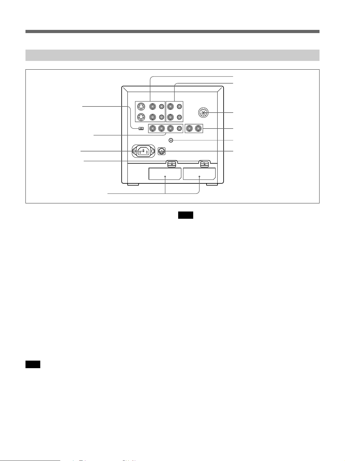
Rear
PVM-9045QM/9042QM
@¢ COMPONENT
LEVEL selector
@∞ RGB/COMPONENT
input connectors
@§ AC IN socket
@¶ EJECT buttons
@• BATTERY compartments
!• LINE A connectors (PVM-9045QM/9042QM)
!• LINE connectors (PVM-9040ME)
Y/C IN (4-pin mini DIN): Connect to the Y/C
separate output of a video camera, VCR or other
video equipment.
Y/C OUT (4-pin mini DIN): Loop-through output of
the Y/C IN connector. Connect to the Y/C separate
input of a VCR or another monitor.
VIDEO IN (BNC): Connect to the video output of a
video camera, VCR or other video equipment.
VIDEO OUT (BNC): Loop-through output of the
VIDEO IN connector. Connect to the video input
of a VCR or another monitor.
AUDIO IN (phono jack): Connect to the audio
output of a VCR or a microphone (through a
suitable microphone amplifier).
AUDIO OUT (phono jack): Loop-through output of
the AUDIO IN connector. Connect to the audio
input of a VCR or another monitor.
Note
The Y/C IN connector has a priority over the VIDEO
IN connector.
When a plug is connected to the Y/C IN connector, the
VIDEO IN connector is automatically disconnected.
!• LINE A connectors
!ª LINE B connectors
@º REMOTE connector
(8-pin mini DIN)
@¡ EXT SYNC (external sync)
connectors
@™ V HOLD (vertical hold) control
@£ DC 12V IN jack (XLR, 4 pin)
Note
(PVM-9045QM/9042QM only)
To monitor the signal fed through these connectors,
keep the LINE/RGB selector and the A/B, RGB/Y R-Y
B-Y selector on the front panel released (LINE and A).
!ª LINE B connectors
To monitor the signal fed through these connectors,
keep the LINE/RGB selector released (LINE) and
depress the A/B, RGB/Y R-Y B-Y selector on the front
panel (B).
VIDEO IN (BNC): Connect to the video output of a
video camera, VCR or other video equipment.
VIDEO OUT (BNC): Loop-through output of the
VIDEO IN connector. Connect to the video input
of a VCR or another monitor.
AUDIO IN (phono jack): Connect to the audio
output of a VCR or a microphone (through a
suitable microphone amplifier).
AUDIO OUT (phono jack): Loop-through output of
the AUDIO IN connector. Connect to the audio
input of a VCR or another monitor.
8 (GB)
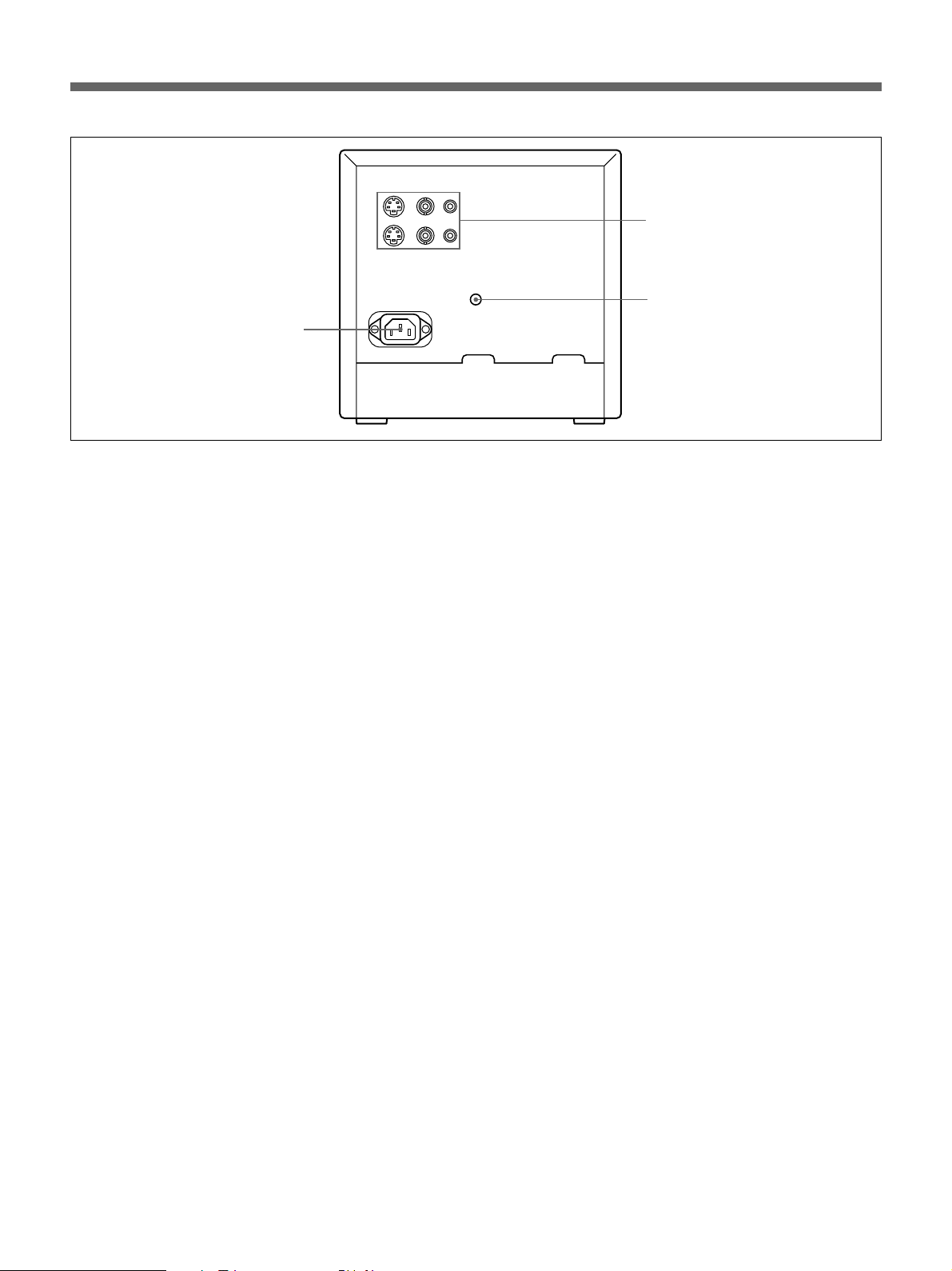
PVM-9040ME
!• LINE connectors
@™ V HOLD (vertical hold)
control
@§ AC IN socket
@º REMOTE connector (8-pin mini DIN)
Connect to the tally output of a control console,
special-effect generator, etc. The tally lamp on the
front panel will be turned on and off by the connected
equipment. This connector can be used for connecting
a remote controller.
For the pin assignment of this connector, see
“Specifications” on page 12 (GB).
@¡ EXT SYNC (external sync) connectors
IN (BNC): When this monitor operates on an
external sync signal, connect the reference signal
from a sync generator to this connector. In this
case, depress the SYNC INT/EXT selector on the
front panel (EXT).
OUT (BNC): Loop-through output of the EXT
SYCN IN connector. Connect to the external sync
input of video equipment to be synchronized with
this monitor.
@™ V HOLD (vertical hold) control
Turn to stabilize the picture if it rolls vertically.
@£ DC 12V IN jack (XLR, 4 pin)
Connect the Sony battery adaptor DC-L10 (not
supplied).
@¢ COMPONENT LEVEL selector
Select the component level from among two modes.
N10/SMPTE: for 100/0/100/0 signal
BETA 0: for 100/0/75/0 signal
@∞ RGB/COMPONENT input connectors
R/R-Y, G/Y, B/B-Y (BNC), AUDIO (phono):
To monitor a signal fed through these connectors,
depress the LINE/RGB selector on the front panel
(RGB). When the SYNC INT/EXT selector on the
front paner is released (INT), the monitor operates on
the sync signal from the G/Y channel.
To monitor the analog RGB signal
Connect to the analog RGB signal outputs of a video
camera. Keep the A/B, RGB/Y R-Y B-Y selector on
the front panel released (RGB).
To monitor the component signal
Connect to the R-Y/Y/B-Y componenet signal outputs
of a Sony BetaCam video camera. Depress the A/B,
RGB/Y R-Y B-Y selector on the front panel (Y R-Y BY).
@§ AC IN socket
Connect the supplied AC power cord to this socket and
to a wall outlet.
@¶ EJECT buttons
Press the EJECT button upwards to remove the battery
pack.
@• BATTERY compartments
Insert the NP-1B battery pack (not supplied).
9 (GB)
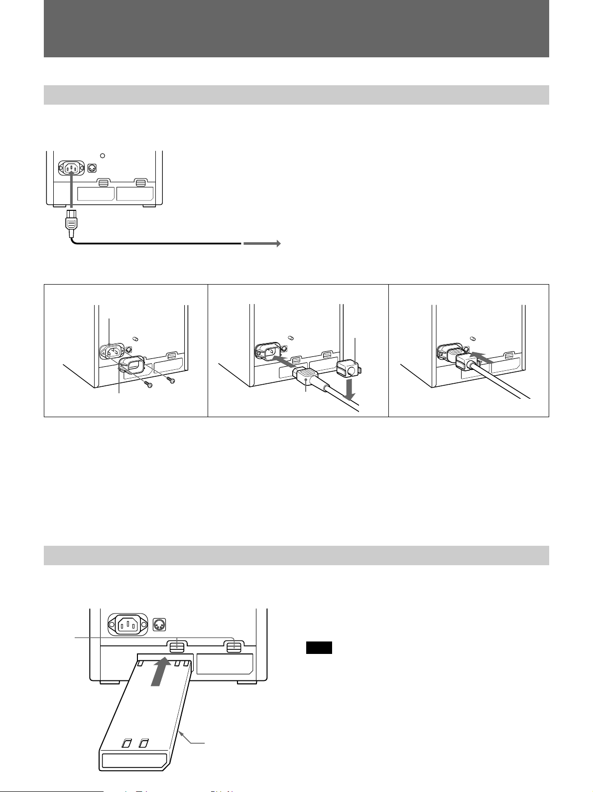
Power Sources
House Current (for all models)
Connect the supplied AC power cord to the AC IN
socket and to a wall outlet.
to AC IN
to a wall outlet
To connect an AC power cord securely with AC plug holders.
For the PVM-9045QM/9042QM
When the AC power cord is plugged into the AC IN
socket, the battery pack (if installed) or the DC 12 V
IN jack (if connected) is automatically disconnected.
21
AC IN socket
AC plug holder A
AC power plug
3
AC plug
holder B
1 Remove the AC IN socket screws and then use
them to attach the AC plug holder A (supplied) to
the AC IN socket.
2 Plug the power cord to the AC IN sokcet. Then,
attach the supplied AC plug holder B on top of the
AC power cord.
3 Slide AC plug holder B over the cord until is locks.
To remove the AC power cord
Pull out AC plug holder B by squeezing the left and
right sides.
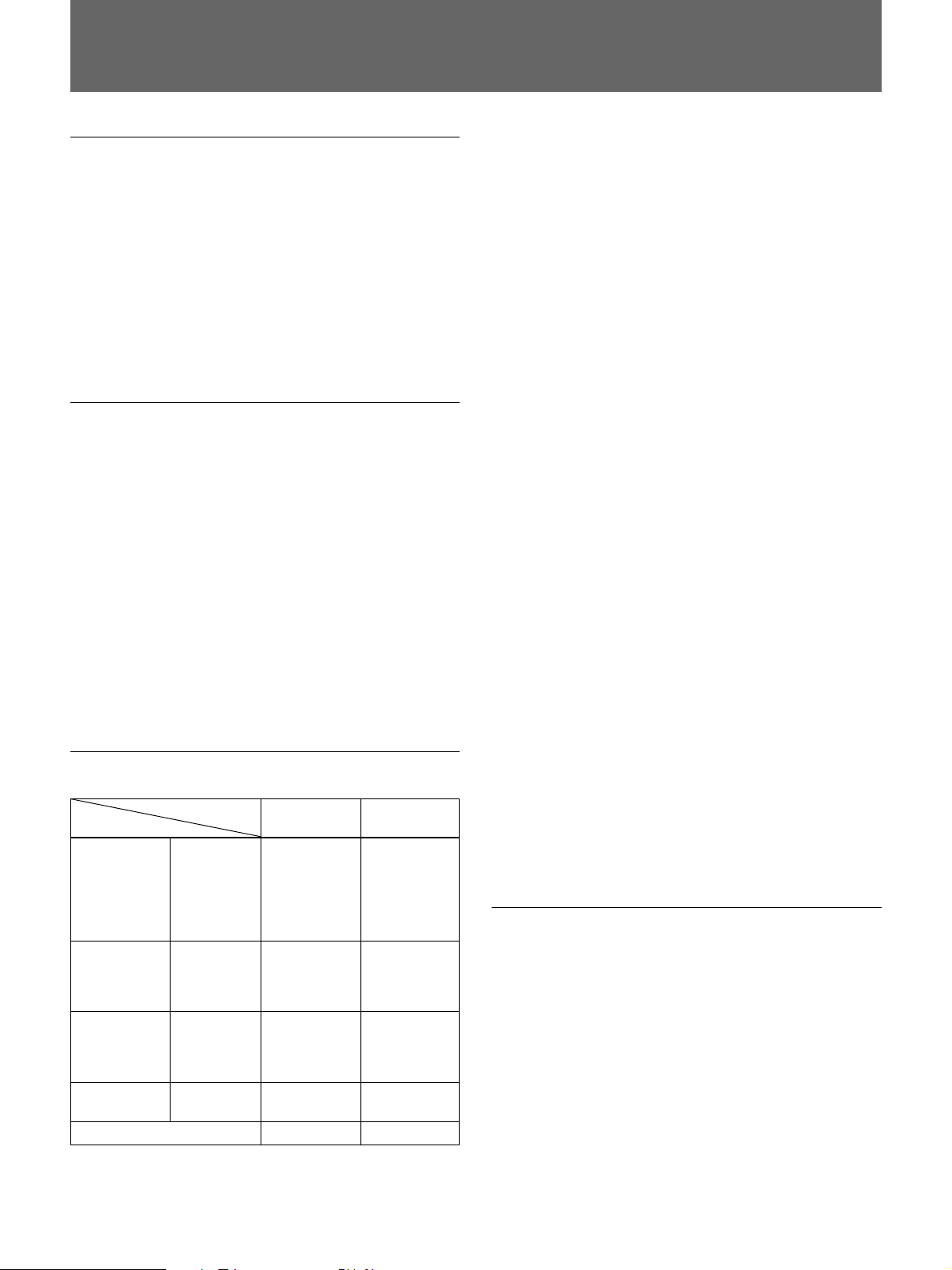
Rechargeable Battery (PVM-9045QM/9042QM only)
The monitor can operate with one or two battery packs.
For extended use, two battery packs are recommended.
EJECT
buttons
NP-1B
(not supplied)
SONY mark downwards
To remove the battery pack, press the EJECT button
upwards.
For charging, use the BC-1WDCE for the NP-1B.
Note
Make sure you disconnect the cables connected to the
connectors (AC IN, DC 12 V IN) at the rear of the
monitor. Otherwise, the monitor cannot operate on the
battery pack(s).
10 (GB)
Specifications
Video signal
Colour system PVM-9045QM/9042QM: PAL,
SECAM, NTSC, NTSC
4.43
PVM-9040ME: PAL, SECAM
Resolution PVM-9045QM: 450 TV lines
PVM-9042QM/9040ME: 250 TV
lines
Aperture correction –4.0 dB to +6.0 dB (at 3.0 MHz)
Frequency response 6.0 MHz (–3.0 dB)
Synchronization AFC time constant 1.0 msec.
Picture performance
Normal scan 6% over scan of CRT effective
screen area
Underscan 3% underscan of CRT effective
screen area
H. linearity Less than 5.0% (typical)
V. linearity Less than 5.0% (typical)
Convergence Central area: 0.43 mm (typical)
Peripheral area: 0.53 mm
(typical)
Raster size stability H: 1.0%, V: 1.5%
High voltage regulation
3.0%
Colour temperature D65
Inputs and Outputs
Model PVM-9045QM PVM-9040ME
Connector PVM-9042QM
LINE A Y/C IN yes yes
LINE B VIDEO IN yes no
RGB/ R/R-Y IN yes no
COMPONENT G/Y IN yes no
EXT SYNC IN yes no
REMOTE yes no
Y/C OUT yes yes
VIDEO IN yes yes
VIDEO OUT yes yes
AUDIO IN yes yes
AUDIO OUT yes yes
VIDEO OUT yes no
AUDIO IN yes no
AUDIO OUT yes no
B/B-Y IN yes no
AUDIO IN yes no
OUT yes no
Inputs Y/C IN: 4-pin mini DIN
connector
See the pin assignment on page
12 (GB).
VIDEO IN: BNC connector
1 Vp-p ± 6 dB, sync negative
AUDIO IN: phono jack, –5 dBu
less than 47 kohms
R/R-Y, G/Y, B/B-Y: BNC
connector
R, G, B channels: 0.7 Vp-p,
± 6 dB Sync on green: 0.3 Vp-p,
negative
R-Y, Y, B-Y channels: 0.7 Vp-p,
±6 dB (Standard colour bar
signal of 100% chrominance)
EXT SYNC IN: BNC connector
Composite sync 4 Vp-p, ±6 dB,
negative
Loop-through outputs
Y/C OUT: 4-pin mini DIN
connector, 75 ohms terminated
(75 ohms automatic termination)
VIDEO OUT: BNC connector,
75 ohms terminated (75 ohms
automatic termination)
AUDIO OUT: phono jack
EXT SYNC OUT: BNC
connector, 75 ohms terminated
Speaker output Output level: 0.5W
Remote input REMOTE: 8-pin mini DIN
connctor (75 ohms automatic
termination)
See the pin assignment on page
12 (GB).
a) 0 dBu = 0.775 Vr.m.s.
General
Power consumption & requirements
PVM-9045QM/9042QM:
0.7 to 0.4A 43W at 100 to 240V
AC operation
3.7A 40W at 12 V DC operation
PVM-9040ME:
0.7 to 0.4A 39W at 100 to 240V
AC operation
a)
,
11 (GB)
Specifications
Peak inrush current
Hot switching inrush current, measured in
accordance with European
standard EN55103-1: 58A
(230V)
Operating conditions
Temperature 0 to +35°C (32 to 95°F)
Humidity 0 to 90% (no condensation)
Pressure 700 to 1060 hPa
Transport and storage conditions
Temperature –10 to +40°C (14 to 104°F)
Humidity 0 to 90%
Pressure 700 to 1060 hPa
Dimensions Approx. 217 x 217 x 352.5 mm
5
(w/h/d) (8
/8 × 8 5/8 × 14 inches)
not incl. projecting parts and
controls
Mass Approx. 8.2 kg (18 lb 1 oz) not
incl. battery packs
Accessory supplied AC power cord (1)
Cable with an 8-pin connector (1)
(PVM-9045QM/9042QM only)
AC plug holders (1 set)
Tally plate (1) (PVM-9045QM/
9042QM only)
Design and specifications are subject to change
without notice.
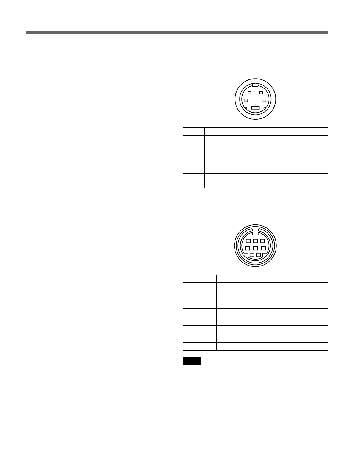
Pin Assignment
Y/C IN connector (4-pin mini DIN)
12
43
Pin No. Signal Description
1 Y-input 1 Vp-p, sync negative, 75 ohms
2 CHROMA 300 mVp-p (PAL), burst
sub-carrier-input Delay time between Y and
3 GND for Y-input GND
4 GND for
CHROMA-input
REMOTE connector (8-pin mini DIN)
(PVM-9045QM/9042QM only)
C: within 0 ±100 nsec., 75 ohms
GND
678
3
45
12
Pin No. Signal
1 16:9
2 H/V delay
3 GND
4 EXT SYNC
5 Tally
6 Underscan
7 A/B or RGB/Y R-Y B-Y
8 LINE/RGB
Notes
•For remote control, connect the pin of the desired
function to pin 3 (GND).
•For remote control, set the front button to OFF (the
switch is out).
12 (GB)


Français
AVERTISSEMENT
Afin d’éviter tout risque d’incendie ou
d’électrocution, ne pas exposer cet appareil à
la pluie ou à l’humidité.
De hautes tensions dangereuses sont
présentes à l’intérieur de l’appareil. Ne pas
ouvrir le coffret. Confier tout travail d’entretien
uniquement à un personnel qualifié.
En cas de dysfonctionnement ou lorsqu’un
entretien s’avère nécessaire,
consultez un revendeur Sony agréé.
CET APPAREIL DOIT ETRE RACCORDE A LA TERRE
Mention importante pour les clients au ROYAUME-UNI
IMPORTANT
Les couleurs des conducteurs du cordon d’alimentation
secteur correspondent au code suivant:
Vert-et-jaune : Terre
Bleu : Neutre
Brun : Phase d’alimentation
ATTENTION:
Il y a un risque d’explosion si la pile est mal insérée.
Remplacer la pile uniquement par une pile de même type ou
de type équivalent recommandé par le fabricant. Jeter les
piles usées conformément aux instructions du fabricant.
Pour les clients européens
Ce produit portant la marque CE est conforme à la fois à la
Directive sur la compatibilité électromagnétique (EMC) (89/
336/CEE) et à la Directive sur les basses tensions (73/23/
CEE) émises par la Commission de la Communauté
européenne.
La conformité à ces directives implique la conformité aux
normes européennes suivantes:
• EN60950: Sécurité des produits
• EN55103-1: Interférences électromagnétiques (émission)
• EN55103-2: Sensibilité électromagnétique (immunité)
Ce produit est prévu pour être utilisé dans les
environnements électromagnétiques suivants:
E1 (résidentiel), E2 (commercial et industrie légère), E3
(urbain extérieur) et E4 (environnement EMC contrôlé ex.
studio de télévision).
Comme ces couleurs peuvent différer des repères colorés
figurant sur votre prise, proceder comme suit: Le fil vert-etjaune doit être conecté à la borne repérée par la lettre E, par
le symbole Y de terre, ou par la couleur verte ou verte-etjaune.
Le fil bleu doit être connecté à la borne repérée par la lettre
N ou par la couleur noire.
Le fil brun doit être connecté à la borne repérée par la lettre
L ou par la couleur rouge.
Assurez-vous que votre appareil est correctement
raccordé. En cas de doute, consultez un
électricien qualifié.
2 (FR)

Précautions
Sécurité
•PVM-9045QM/9042QM: Faire fonctionner l’appareil
sur courant alternatif de 100 – 240 V ou sur courant
continu de 12 V. Pour faire foncionner l’appareil sur le
courant alternatif, utiliser le cordon alimentation
secteur fourni ou l’adaptateur d’alimentation secteur
recommandé (non fourni).
Pour faire fonctionner l’appareil sur batterie, utilisez
uniquement une batterie NP-1B ou BP-L60A/L90A
avec l’adaptateur DC-L10 (non fournis). N’utilisez
aucun autre type de batterie.
•PVM-9040ME: Faire fonctionner l’appareil
uniquement sur courant alternatif de 100 – 240 V.
Utiliser le cordon d’alimentation secteur fourni avec
l’appareil et aucun autre.
•Si un solide ou un liquide pénètre dans le coffret,
débrancher l’appareil et le faire vérifier par un
technicien qualifié avant de le remettre en service.
•Débrancher l’appareil de la prise secteur s’il ne doit
pas être utilisé pendant plusieurs jours.
•Pour déconnecter le cordon, tirer sur la fiche. Ne
jamais tirer sur le cordon proprement dit.
Installation
•Prévoir une circulation d’air adéquate pour éviter une
surchauffe à l’intérieur de l’appareil. Ne pas placer
l’appareil sur une surface molle, comme un tapis ou
une couverture, ou près de rideaux ou de draperies
qui risqueraient d’obstruer les fentes d’aération.
•Ne pas installer l’appareil près d’une source de
chaleur, comme un radiateur ou une bouche d’air
chaud, ou dans un endroit exposé au soleil, à de la
poussière excessive, des vibrations mécaniques ou
des chocs.
•Ne pas installer l’appareil près d’un haut-parleur ou
d’un moteur qui pourraient affecter l’image.
Nettoyage
Nettoyer l’appareil avec un chiffon doux et humide.
Ne jamais utiliser de solvant puissant, comme du
diluant ou de la benzine qui pourraient endommager la
finition. Par mesure de précaution, débrancher
l’appareil avant de le nettoyer.
Remballage
Conserver le carton et les matériaux d’emballage car
ils offrent une protection idéale si l’appareil doit être
expédié vers une autre destination.
Pour toute question ou problème au sujet de cet
appareil, veuillez contacter votre revendeur Sony
agréé.
ATTENTION – Si l’appareil est
installé dans une étagère:
a) Température ambiante de service élevée
Si l’appareil est installé dans une étagère fermée ou
dans une étagère multi-appareil, la température
ambiante dans l’étagère peut être supérieure à la
température ambiante du local. Il convient par
conséquent de veiller à installer l’appareil dans un
environnement compatible avec la température
ambiante nominale maximum spécifiée par le
fabricant, c’est-à-dire entre 0 et +35°C (32 et 95°F)
(Tmra).
b) Circulation de l’air
L’installation de l’appareil dans une étagère doit
être telle que le flux d’air requis pour un
fonctionnement sûr de l’appareil ne soit pas
entravé.
c) Charge mécanique
Le montage de l’appareil dans l’étagère doit être
réalisé de façon à prévenir tout risque de danger
résultant d’une mauvaise répartition de la charge
mécanique.
d) Surcharge de circuit
Il convient de veiller à raccorder correctement
l’appareil au circuit d’alimentation, aux effets d’une
surcharge du circuit sur la protection contre les
courants de surcharge et le câblage du circuit
d’alimentation.
Conformez-vous à cet égard aux spécifications
mentionnées sur la plaquette signalétique.
e) Mise à la terre fiable
Assurez une mise à la terre fiable de l’appareil
installé dans une étagère. Veillez plus
particulièrement à réaliser des connexions
d’alimentation autres que des connexions directes
au circuit de dérivation (par ex., au moyen de
bandelettes d’alimentation).
f) Interstices
Les espaces libres au-dessus et en-dessous de
l’appareil installé dans une étagère doivent être
d’au moins 44 mm (1
3
/4 pouces).
3 (FR)
FR
Française
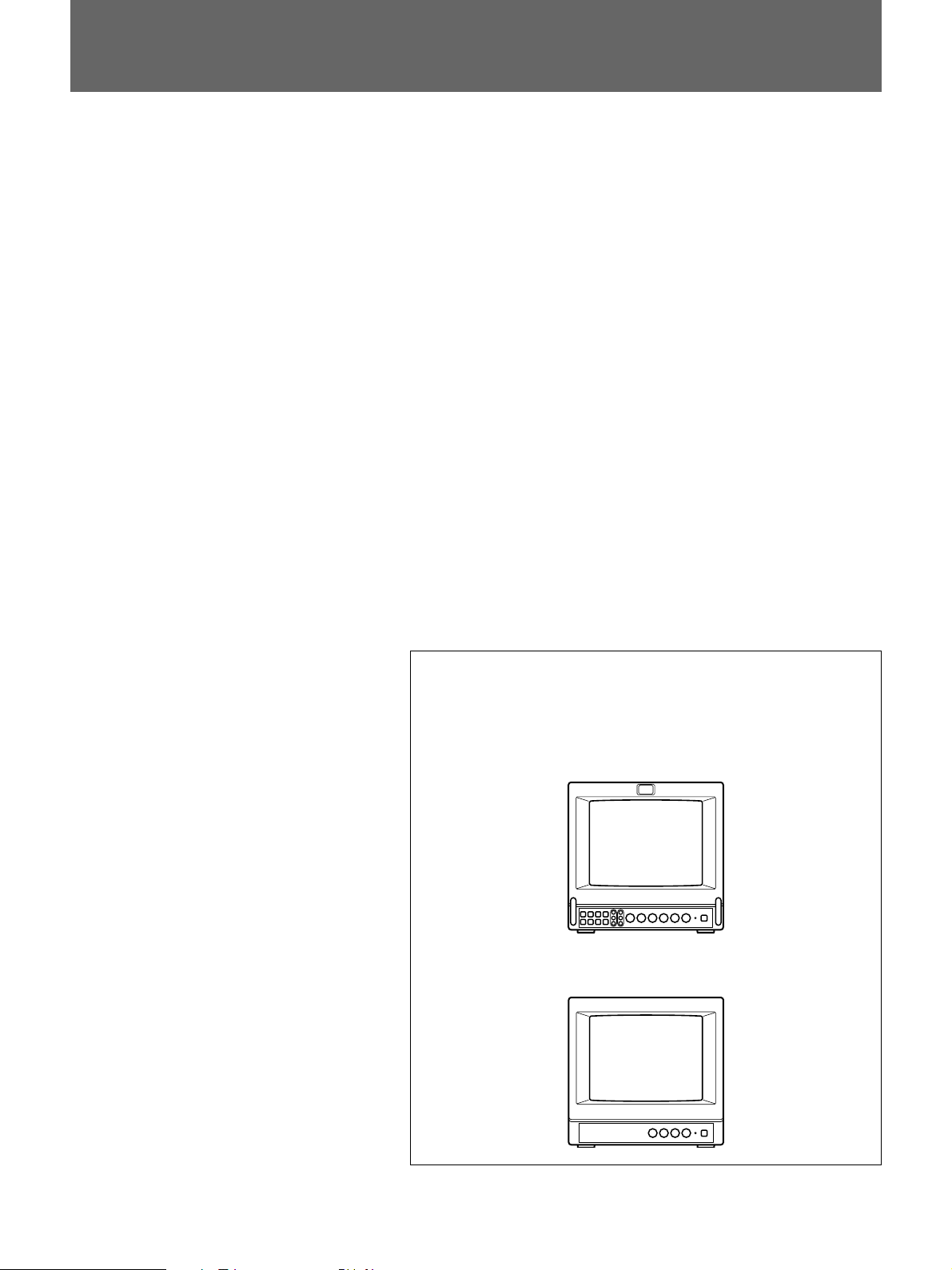
Table des matières
Caractéristiques ................................................................ 5
Nomenclature..................................................................... 6
Avant ..................................................................................6
Arrière ................................................................................8
Sources d’alimentation ................................................... 10
Spécifications .................................................................. 11
Ce mode d’emploi couvre les modèles PVM-9045QM, PVM9042QM et PVM-9040ME. Les différences entre les modèles
sont clairement spécifiées dans le texte.
PVM-9045QM/9042QM
PVM-9040ME
4 (FR)

Caractéristiques
Quatre systèmes de codage couleur
(PVM-9045QM/9042QM uniquement)
Le moniteur peut afficher des signaux PAL, SECAM,
1)
4.43
NTSC et NTSC
. Le système de couleur approprié
est sélectionné automatiquement.
® 2)
Tube image Trinitron
HR (haute définition)
(PVM-9045QM)
Le tube image Trinitron HR (pas d’ouverture de grille
de 0,25 mm) fournit une image à haute résolution. La
résolution horizontale est supérieure à 450 lignes TV
au centre de l’image.
Tube image Trinitron (PVM-9042QM/9040ME)
Le tube image Trinitron (pas d’ouverture de grille de
0,5 mm) fournit une image à haute résolution. La
résolution horizontale est supérieure à 250 lignes TV
au centre de l’image.
Circuit de rétroaction du courant du faisceau
Le circuit de rétroaction du courant du faisceau assure
la stabilité de la balance du blanc.
Sélecteur 16:9
(PVM-9045QM/9042QM uniquement)
Le moniteur peut afficher le signal 16:9 avec le rapport
hauteur/largeur adéquat en comprimant l’image
verticalement.
Mode de sous-balayage
(PVM-9045QM/9042QM uniquement)
Le moniteur peut afficher des signaux scannés à
l’extérieur de l’écran normal de façon à ce que vous
puissiez contrôler la totalité de l’image.
Circuit audio et haut-parleur intégré
Un haut-parleur (0,5 W, monaural) est intégré dans le
moniteur pour le contrôle du son.
DEGAUSS automatique/manuel
L’écran est automatiquement démagnétisé lorsque le
moniteur est mis sous tension. Sur les moniteurs PVM9045QM/9042QM, vous pouvez également
démagnétiser l’écran manuellement en appuyant sur la
touche DEGAUSS.
Signaux d’entrée multiples
(PVM-9045QM/9042QM uniquement)
En plus des signaux vidéo composites et des signaux
Y/C, vous pouvez également entrer des signaux
composant.
Entrée de synchronisation externe
(PVM-9045QM/9042QM uniquement)
Lorsque la touche EXT SYNC est enfoncée, le
moniteur peut fonctionner sur le signal de
synchronisation transmis via un connecteur de
synchronisation externe.
Image bleue
(PVM-9045QM/9042QM uniquement)
Une image noir et blanc uniquement composée du
signal bleu s’affiche. Ce procédé simplifie le réglage
de la phase et du niveau chromatique ainsi que
l’observation des interférences vidéo.
Terminaison automatique
(les connecteurs portant le repère
uniquement)
Les connecteurs Y/C, VIDEO IN et EXT SYNC IN ont
une terminaison interne de 75 ohms si aucun câble
n’est raccordé aux connecteurs de sortie directe. Si un
câble est raccordé au connecteur de sortie, la
terminaison de 75 ohms est automatiquement libérée.
Montage en rack 19 pouces à la norme EIA
Si vous utilisez une armature de montage MB-520
(non fournie), vous pouvez monter le moniteur sur un
rack 19 pouces à la norme EIA. Pour plus de détails
sur le montage, voir le mode d’emploi de la MB-520.
Plusieurs sources d’alimentation
En plus de l’alimentation secteur, vous pouvez utiliser
une batterie ou une alimentation externe de 12 V CC.
Le moniteur peut fonctionner avec une ou deux
batteries Sony NP-1B*. Si vous utilisez un adaptateur
de batterie DC-L10*, le moniteur peut fonctionner
avec une batterie ion-lithium Sony BP-L60A/L90A*.
* La batterie NP-1B, l’adaptateur de batterie DC-L10
et les batteries BP-L60A/L90A ne sont pas fournis.
..........................................................................................................................................................................................................
1) Vous obtenez un signal NTSC4.43 lors de la lecture d’une vidéocassette NTSC sur un enregistreur/lecteur vidéo conçu
spécialement pour ce système.
2) Trinitron est une marque déposée de Sony Corporation.
5 (FR)
Nomenclature
Avant
PVM-9045QM/9042QM
9 Touche DEGAUSS
!º Sélecteur de synchronisation
interne/externe (SYNC INT/EXT)
!¡ Sélecteur d’entrée de ligne/
RVB (LINE/RGB)
!™ Sélecteur d’entrée
(A/B, RGB/Y R-Y B-Y)
!£ Sélecteur d’image bleue
(BLUE ONLY)
!¢ Sélecteur UNDER SCAN
!∞ Sélecteur de retard horizontal/
vertical (H/V DELAY)
!§ Sélecteur 16:9
!¶ Touches de réglage de polarisation
RVB (R/G/B BIAS) et de gain (GAIN)
1 Témoin de signalisation
Cet indicateur s’allume. Il faut alors utiliser la
connexion de commande de l’indicateur.
Pour l’attribution des broches, reportez-vous aux
“Spécifications” à la page 12 (FR).
2 Interrupteur et témoin d’alimentation
(POWER)
Enclencher cet interrupteur pour allumer le moniteur.
Le témoin s’allume en vert.
Le témoin POWER sert aussi de témoin d’état de la
batterie. Quand la batterie interne faiblit, ou quand
l’alimentation fournie par la prise DC 12 V IN
diminue, ce témoin clignote.
3 Réglage d’intensité sonore (VOLUME)
Tourner ce réglage dans le sens des aiguilles d’une
montre ou dans le sens contraire pour obtenir
l’intensité sonore souhaitée.
4 Réglage du contraste (CONTR)
Tourner dans le sens des aiguilles d’une montre pour
accentuer le contraste, ou dans le sens contraire pour le
diminuer.
5 Réglage de phase (PHASE)
Ce réglage ne concerne que les systèmes couleur
NTSC et NTSC
4.43. Tourner dans le sens des aiguilles
d’une montre pour que le teint tende vers le vert, et
dans le sens contraire pour le faire tendre vers le violet.
6 (FR)
1 Témoin de signalisation
2 Interrupteur et témoin
d’alimentation (POWER)
3 Réglage d’intensité sonore
(VOLUME)
4 Réglage du contraste (CONTR)
5 Réglage de phase (PHASE)
6 Réglage de chrominance
(CHROMA)
7 Réglage de luminosité (BRIGHT)
8 Réglage d’ouverture (APER)
6 Réglage de chrominance (CHROMA)
Tourner dans le sens des aiguilles d’une montre pour
augmenter l’intensité des couleurs, et dans le sens
contraire pour la réduire.
7 Réglage de luminosité (BRIGHT)
Tourner dans le sens des aiguilles d’une montre pour
augmenter la luminosité, et dans le sens contraire pour
la réduire.
8 Réglage d’ouverture (APER)
Tourner dans le sens des aiguilles d’une montre pour
augmenter la netteté, et dans le sens contraire pour le
réduire.
Remarques
•Les réglages PHASE, CHROMA et APER n’agissent
pas sur le signal analogique RVB.
•La commande PHASE n’agit pas sur les signaux
composants.
•Le réglage PHASE n’est valide que pour le système
NTSC.
9 Touche DEGAUSS
Appuyez brièvement sur cette touche. L’écran est
démagnétisé.
Remarque
Si vous appuyez à nouveau trop tôt sur la touche
DEGAUSS, les tonalités risquent de ne pas être
uniformes.
PVM-9040ME
7 Réglage de luminosité (BRIGHT)
6 Réglage de chrominance (CHROMA)
2 Interrupteur et témoin
d’alimentation (POWER)
3 Réglage d’intensité sonore
(VOLUME)
4 Réglage du contraste (CONTR)
!º Sélecteur de synchronisation interne/externe
(SYNC INT/EXT)
La touche doit être sortie (position INT) pour faire
fonctionner le moniteur sur le signal de
synchronisation du signal vidéo composite affiché.
Enclencher cette touche (position EXT) pour faire
fonctionner le moniteur sur un signal de
synchronisation externe fourni au connecteur EXT
SYNC à l’arrière.
!¡ Sélecteur d’entrée de ligne/RVB (LINE/RGB)
Il sert à sélectionner le programme à contrôler. La
touche doit être sortie (LINE) pour un signal fourni
aux connecteurs LINE A ou LINE B. Enclencher cette
touche (RGB) pour un signal fourni par les
connecteurs RGB.
!™ Sélecteur d’entrée (A/B, RGB/Y R-Y B-Y)
Quand le sélecteur d’entrée LINE/RGB est
positionné sur LINE
La touche doit être sortie (A) pour un signal fourni aux
connecteurs LINE A. Appuyez sur cette touche (B)
pour contrôler les signaux transmis via les connecteurs
LINE B.
Quand le sélecteur d’entrée LINE/RGB est
positionné sur RGB
Sélectionner le signal RGB ou le signal de
composantes fourni aux connecteurs d’entrée RGB. La
touche doit être sortie (RGB) pour un signal RGB.
Appuyez sur cette touche (Y R-Y B-Y) pour contrôler
les signaux composant.
!£ Sélecteur d’image bleue (BLUE ONLY)
Appuyer sur ce sélecteur pour couper les signaux
rouge et vert. Un signal bleu est affiché comme une
image monochrome sur l’écran. Cette fonction facilite
les ajustements de chrominance, ainsi que
l’observation du bruit vidéo.
!¢ Sélecteur UNDER SCAN
Appuyez sur ce bouton pour le sous-balayage. Le
format d’affichage est réduit d’approximativement 3 %
de façon à ce que les quatre coins de l’image soient
visibles.
!∞ Sélecteur de retard horizontal/vertical (H/V
DELAY)
Enclencher cette touche pour observer les signaux de
synchronisation horizontale et verticale en même
temps. Le signal de synchronisation horizontale est
affiché dans le quart gauche de l’écran; le signal de
synchronisation verticale est affiché près du centre de
l’écran.
!§ Sélecteur 16:9
Appuyez sur ce sélecteur (témoin allumé) pour
contrôler les signaux d’une image 16:9e. Une pression
sur la sélecteur UNDER SCAN !¢ en mode 16:9e
commande l’affichage de la totalité de l’image 16:9
jusqu’aux quatre angles.
!¶ Touches de réglage de polarisation RVB (R/G/B
BIAS) et de gain (GAIN)
Elles servent au réglage fin de la balance du blanc. Les
réglages BIAS et GAIN servent à régler les écrans
rouge (R), vert (G) et bleu (B).
BIAS: Pour ajuster la balance du blanc et la
luminosité de l’écran sous un éclairage réduit.
GAIN: Pour ajuster la balance du blanc et la
luminosité de l’écran sous un éclairage fort.
7 (FR)
 Loading...