

SONY PVM-14M2MDU, PVM-14M2MDE, PVM-14M2MDA, PVM-20M2MDU, PVM-20M2MDE User manual
...
SERVICE
LT て ロマ で エイ
エイ
1
MANUAL
DEST.
απ
τ.μ
CHASSIS
NO,
ωνη
CYPYTTYYTYTTTT
at
PVM-14M2MDU
PVM-14M2MDE
PVM-14M2MDA
υ5
Canadian
AEP
Australian
SCC-N59B-A
SCC-N33F-A
SCC-N17E-A
PVM-20M2MDU
PVM-20M2MDE
PVM-20M2MDA
US
Canadian
AEP
Australian
SCC-N59A-A
SCC-N33E-A
SCC-N17D-A
TRINITRON:
COLOR
VIDEO
SONY.
MONITOR

SPECIFICATIONS
Video
For
20M2MDU/20M2MDE/20M2MDA:
Color
Resolution
Aperture
Frequency
Synchronization
Picture
For
Normal
Under
|
Over
H.
V.
Convergence
Raster
High
Color
For
Normal
Under
signal
PVM-14M2MDU/14M2MDE/14M2MDA/
system
correction
response
LINE
RGB
NTSC,
600
TV
0
dB
10
MHz
10
MHz + 3
AFC
performance
PVM-14M2MDU/14M2MDE/14M2MDA:
scan
scan
scan
linearity
linearity
Central
Peripheral
Over
H.
linearity
V.
linearity
Convergence
area:
size
stability
voltage
temperature
PVM-20M2MDU/20M2MDE/20M2MDA
scan
scan
scan
Central
area:
Peripheral
Raster
size
stability
High
voltage
Color
temperature
7 % over
screen
%
5
screen
%
20
screen
Less
Less
Less
area:
Less
H:
regulation
3.5
D65/D56/D93,
USER
setting
%
7
screen
%
5
screen
20
screen
Less
Less
Less
area:
Less
H:
regulation
4.0%
D65/D56/D93,
USER
setting
1.0%,
%
%
1.0%,
PAL
lines
to
+6
dB
+ 3
dB
(Y
signal)
dB
time
constant
scan
area
underscan
area
scan
over
area
than
4.0 % (typical)
than
4.0 % (typical)
than
0.4
than
0.5
V:
(3,200K-10,000K,
1s
D65)
scan
over
area
underscan
area
scan
over
area
than
5.0 % (typical)
than
5.0 % (typical)
0.6
than
than
1.0
V:
(3,200K—10,000K,
is
D65)
1.0
of
CRT
CRT
of
CRT
of
mm
(typical)
mm
(typical)
1.5%
selectable
CRT
of
CRT
of
CRT
of
(typical)
mm
mm
(typical)
1.5%
selectable
msec.
effective
effective
effective
factory
effective
effective
effective
factory
Inputs
LINE
LINE
RGB/COMPONENT
EXT
REMOTE
(common
A
VIDEO
AUDIO
Y/C
AUDIO
R/R-Y,G/Y,B/B-Y
AUDIO
B
IN
SYNC
IN
IN
IN
R,
G, B channels:
R-Y,
B-Y
Y
channel:
IN
IN
to
all
models)
BNC
connector,
negative
Phono
jack
(x1),
47
kilo-ohms
4-pin
mini-DIN
See
the
pin
assignment
(x1),
jack
Phono
47
kilo-ohms
A/B
IN:
BNC
connector
0.7
Sync
on
green:
channels:
0.7
Vp-p,
(Standard
chrominance)
Phono
47
BNC
4
Vp-p,
D
color
jack
(x1),
kilo-ohms
connector
+6
dB,
SUB 9 PIN
(x1)
See
the
pin
assignment
1Vp-p
-5
dBu®,
(x1)
dBu®,
—5
Vp-p,
+6
0.3
Vp-p,
0.7
Vp-p,
£6
dB
bar
signal
—5
dBu“,
(<1)
sync
negative
(X1), 8 PIN
|
+6
on
page
(x3)
dB
negative
+6
of
|
on
page
dB,
sync
more
more
dB
75%
more
MIN
than
37.
than
than
DIN
37.
a) 0 dBu = 0.775
Outputs
LINEA
VIDEO
|
.
AUDIO
LINE
B
Y/C
OUT
AUDIO
RGB/COMPONENT
R/R-Y,G/Y,B/B-Y
AUDIO
EXT
SYNC
DC
OUT
Speaker
output
Vr.m.s.
(common
OUT
OUT
OUT
OUT
OUT
to
all
BNC
connector
Automatic
Phono
4-pin
Automatic
Phono
A
OUT:
loop-through
Automatic
Phono
BNC
Automatic
8
V/0.8A
Output
75
jack
loop-through
mini-DIN
75
jack
(x1)
BNC
75
jack
(x1)
connector
75
level:
models)
(x1)
loop-through,
ohms
termination
(x1)
loop-through,
ohms
termination
loop-through
connector
ohms
termination
loop-through
(x1)
ohms
termination
0.8
W
(x3)
General
Classification
—
Evaluated
(common
of
to
EN60601-1,
CSA601.1
~
Type
of
protection
—
Degree
of
protection
—
Degree
of
safety
flammable
—
Mode
—
Information
maintenance
—
Main
CRT
Operating
Transport
Accessories
For
PVM-14M2MDU:
Power
Dimensions
Mass
For
PVM-14M2MDE/14M2MDA:
Power
Dimensions
Mass
anaesthetic
of
operation
concerning
power
switch
conditions
0
to
+40°C
700
to
1,060
30
to
85%
and
Storage
-10
to
+40°C
700
to
1,060
0
to
90%
supplied
requirements
(w/h/d)
requirements
(w/h/d)
to
equipment
EN60601-1-2,
against
electric
Class I equipment
against
Ordinary
of
application
mixture
Not
protected
Continuous
type
Not
need
Functional
P-22
phosphor
(32
to
104°F)
hPa
Pressure
(no
condensation)
conditions
(14
to
104°F)
hPa
Pressure
Humidity
AC
power
AC
plug
Side
Cover
Control
Panel
Remote
DIN
Interface
panel
hinge
(1)
(1)
Instructions
1.2 — 0.5A
100
to
240 V AC,
Approx.
(13% x 1334 x 17
not
incl.
Approx.
1.2
-0.5A
100
to
240 V AC,
Approx.
(13% x 1314 x 17
not
incl.
Approx.
all
models)
UL2601-1,
shock
harmful
ingress
equipment
in
the
presence
|
equipment
operation
and
frequency
maintenance
switch
Temperature
Humidity
Temperature
cord
(1)
holder
(1)
(2)
cover
(1)
(2)
control
connector
Manual
346 x 340 x 431
projecting
16.7kg
346 x 340 x 431
projecting
16.7kg
for
.
for
Programmers
Use
(1)
50/60Hz
inches)
parts
(36
Ib
50/60Hz!)
inches)
parts
(36
Ib
of
water
of
of
technical
equipment
8-pin
り
mm
and
controls
13
oz)
mm
|
and
controls
13
oz)
a
mini
For
PVM-20M2MDU:
Power
requirements
Dimensions
Mass
For
Power
Dimensions
Mass
Design
- À
without
(w/h/d)
PVM-20M2MDE/20M2MDA:
requirements
(w/h/d)
and
specifications
notice.
1.5 - 0.6A
100
to
240 V AC.
Approx.
(1734
not
Approx.
450 x 458 x 503
x18L8 x 19%
incl.
projecting
30.0
1.5 - 0.6A
100
to
240 V AC,
Approx.
(17%
not
Approx.
450 x 458 x 503
x18/4 x 1974
incl.
projecting
30.0
are
50/60Hz
parts
kg
(66
50/60Hz
parts
kg
(66
subject
to
1)
mm
inches)
and
controls
1b 2 oz)
Y
mm
inches)
and
controls
1b 2 oz)
change
1)
Use a proper
power
cord
for
your
local
power
supply.
(See
—3—
page
22.)

Y/C
IN
2
3
4
connector
(4-pin
CHROMA
subcarrier-input | Vp-p
for
GND
GND
for
CHROMA-
mini-DIN)
input
|
Y-input
75
ohms
300m
(NTSC),
Delay
and
C:
nsec.,
GND
GND
Vp-p
(PAL)/286m
burst
time
between
within 0 +
75
100
ohms
Y
REMOTE
LINE
GND
LINE
ER
RGB
A
RGB
|
A
B
SCAN
B
ON/OFF
1
2
3
4
=
7
8
RS-232C
(D-sub
1
2
3
4
5
6
7
8
9
9-pin)
909000
© © 9
©
After
correcting
the
perform
the set
to
the
metal
Check
exposed
other
as
leakage
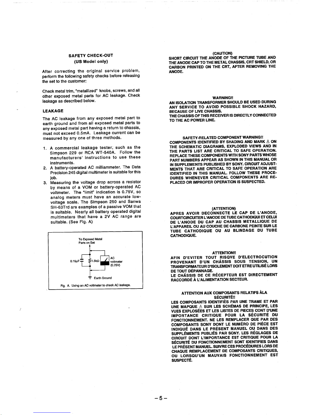
LEAKAGE
The
AC
earth
any
must
measured
1.
leakage
ground
exposed
not
exceed
commercial
A
Simpson
manufacturers'
instruments.
battery-operated
A
Precision
job.
Measuring
means
by
voltmeter.
analog
voltage
SH-63Trd
suitable.
is
multimeters
suitable.
SAFETY
(US
the
following
customer:
“metallized”
trim,
metal
described
from
and
from
metal
0.5mA.
by
any
one
or
229
digital
245
the
a
of
The
meters
scale.
examples
are
Nearly
that
Fig.
(See
To
Parts
CHECK-OUT
Model
only)
original
checks
safety
knobs,
for
parts
below.
any
exposed
all
exposed
having
part
Leakage
of
three
leakage
WT-540A.
RCA
instructions
milliammeter.
AC
multimeter
VOM
“limit”
must
Simpson
all
have
A)
Exposed
on
Set
drop
or
indication
have
of
battery
Metal
voltage
The
service
AC
a
methods.
tester;
before
screws,
leakage.
metal
metal
return
current
such
problem,
releasing
and
Check
part
paris
chassis,
to
can
as
Follow
these
use
to
The
for
suitable
is
resistor
a
across
battery-operated
0.75V,
is
accurate
a
a
2V
an
250
passive
operated
AC
and
VOM
range
Sanwa
digital
all
to
to
be
the
the
Data
this
AC
so
low-
that
are
SHORT
CIRCUIT
THE
ANODE
CARBON
PRINTED
ANODE.
AN
ISOLATION
ANY
SERVICE
BECAUSE
THE
TO
COMPONENTS
THE
THE
REPLACE
PART
IN
MENTS
IDENTIFIED
DURES
PLACED
APRES
COURTCIRCUITER
DE
L'APPAREIL
TUBE
CATHODIQUE.
OF
CHASSIS
THE
AC
POWER
SAFETY-RELATED
SCHEMATIC
PARTS
THESE
NUMBERS
SUPPLEMENTS
THAT
WHENEVER
OR
AVOIR
L'ANODE
CATHODIQUE
THE
CAP
TO
TRANSFORMER
TO
LIVE
OF
THIS
IDENTIFIED
LIST
COMPONENTS
APPEAR
ARE
IN
THIS
IMPROPER
DECONNECTE
DU
OU
AU
(CAUTION)
ANODE
THE
METAL
ON
THE
WARNING!
AVOID
CHASSIS.
RECEIVER
LINE.
DIAGRAMS,
ARE
CRITICAL
PUBLISHED
CRITICAL
MANUAL.
CRITICAL
OPERATION
(ATTENTION)
L'ANODE
CAP
AU
COUCHE
OU
OF
THE
CHASSIS,
CRT,
SHOULD
POSSIBLE
IS
COMPONENT
BY
SHADING
EXPLODED
WITH
AS
SHOWN
BY
TO
FOLLOW
COMPONENTS
DE
TUBE
CHASSIS
DE
CARBONE
AU
PICTURE
AFTER
SHOCK
DIRECTLY
WARNING!
TO
SAFE
SONY
IN
SONY.
SAFE
iS
SUSPECTED.
LE
CAP
CATHODIQUI
BLINDAGE
TUBE
CRT
SHIELD,
REMOVING
BE
USED
HAZARD,
CONNECTED
AND
MARK A ON
VIEWS
OPERATION.
PARTS
THIS
MANUAL
CIRCUIT
OPERATION
THESE
DE
L'ANODE,
METALLIQUE
PEINTE
DU
AND
THE
DURING
AND
WHOSE
ADJUST-
ARE
PROCE-
ARE
ET
CELUI
SUR
TUBE
OR
IN
OR
RE-
DE
LE
Fig.
A.
DAFT
Using
an
=1.5ко
4
=
AC
voltmeter
Earth
Ground
to
check
AC
voltmeter
(0.754)
AC
leakage.
AFIN
D'EVITER
PROVENANT
TRANSFORMATEUR
DE
TOUT
DEPANNAGE.
CHASSIS
LE
RACCORDE A L'ALIMENTATION
ATTENTION
D'UN
DE
TOUT
CE
AUX
ATTENTION!
RISQVE
CHASSIS
D'ISOLEMENT
RECEPTEUR
COMPOSANTS
SÉCURITÉ!
LES
COMPOSANTS
MAPQUE À SUR
UNE
VUES
EXPLOSÉES
IMPORTANCE
FONCTIONNEMENT.
COMPOSANTS
INDIQUE
DANS
SUPPLEMENTS
CIRCUIT
SECURITE
LE
CHAQUE
OU
DONT
DU
PRESENT
REMPLACEMENT
LORSQU'UN
IDENTIFIES
LES
ET
LES
CRITIQUE
NE
LE
LES
DONT
PRESENT
PAR
SONY
PUBLIES
L'IMPORTANCE
FONCTIONNEMENT
MANUEL.
SUIVRE
MAUVAIS
SUSPECTE.
D'ELECTROCUTION
SOUS
DOIT
SECTEUR.
PAR
SCHÉMAS
LISTES
DE
POUR
REMPLACER
LE
NUMÉRO
MANUEL
SONY.
EST
SONT
CES
PROCEDURES
DE
COMPOSANTS
FONCTIONNEMENT
TENSION,
ETRE
DIRECTEMENT
EST
RELATIFS
UNE
TRAME
DE
PRINCIPE,
PIECES
LA
SÉCURITÉ
QUE
DE
OU
LES
REGLAGES
CRITIQUE
IDENTIFIES
UTILISE
ALA
ET
CONT
D'UNE
PAR
PIÉCE
DANS
POUR
LORS
CRITIQUES,
UN
LORS
PAR
LES
DU
DES
EST
DES
DE
LA
DANS
DE
EST


MEME
a
σοι
Uy
ONTRA
parogyas
15nÍpe
30
(q)
10530
uopng
suopnq
YE
NVOSHHAO
GAOU
()
"SIUQUI
414)
01
5024
94
4
の
OD
UT
ER
*urede
30
st
azis
791493
uonnq
“go
Aepdsip
0411641
481)
ou
94],
2718
mmssard
05
“SUJUUEOSIDAO
unou
%02
Ag
ATeletnrx0ndde
“yoyem
sm
0)
10]
sunget
03
(U0
191509
&q
148311)
Kejdsip
papuarxe
51
029108
56910
om
9
st
30
ozis
ap
$190109
“urede
Avpdstp
№10}
пода
94],
yeyi
‘Sutuuvosispun
243
Os
30155224
94
Ájoreupxosúde
uoyng
Ag
Joy
“SEESIA
NVOSHAGNO
(U0
19811)
Aq
e
paonpel
391S91
55944
OD
«(390
1081)
9Z75
TeunJou
alp
07
suyas
ἀτ[άςιρ
ur
Sumos
st
19591
0}
ssaud
‘syuounsnf{pe
uoyng
nuaw
"muau
LASAH
Suunq
SY
sun
ad
[TMA
Supeanot
usalos
910399
SUL
"ATHBIUOUION
21041
10
SOINUTUL
uoyng
HONG
“paznauğeuap
ssnvoad
QT
SAP
107
55224
HEM
©
ny,
Td
Go
oii
vaio
ue
JUIN
D
“ureSz
noyng
È
ми
出
$124
$1
usssas
JU)
“(uo
OJIYAA
34311)
ÁJTLORLIGA
suoyynq
peuSis
399188
S[[OJ
8
Ῥοσπουδειπορ
199198
910191d
4/V
O1
ANIT
SSOI
SUL
由
-o
-@
777
СЕ
Y
E
ANTI
ANTI
p
Su
snmp
pay
sun
UŠNOJ
Pops
pay
UPS
reudts
g/V
SU
am
INENOdHOJ/80U4
*SJ0329UU03
“s10}99UU09
JOJEUOTU
Jojtuoul
0)
01
SIIT
Indur
30041
55914
V
ig
D
pue
JoSuons
ÁJSUSIUI
onuo2
"JOJBOM
10.103
JOJ03
(3ouwuitu0rH2)
JI
DU
(ssamuyJug)
OJVTU
SNELI
0)
0)
95IA901931un09
9814202
INOHHO
LHDRIG
UMI,
T-
©
©
O
|
‘2g
와
a8nd
4014080003
uo
,
suouvoifioads,,
[04002
시
01
341
aas
‘do
‘tuauudisse
SYST
дозор
401821001
uid
"08000
24
årer
514,
40
|
/AOM
{POA
Mp
MY
UBNoNN
YFnonp
"$10709uu09
"810094400
poy
poy
πο
[20815
peusts
ЗН)
Indu!
1ndur
241
эф
ŒUBIS
y
4
20100:
IOHUOLU
LNANOWOO
LNANOJAOJ
®
729128
01
0)
$8944
$$91
01
55244
LY
AT
pure
рие
SS9r
552141945
Tg
BOUL
IO
OStMADO]O
WIN,
XOPEOIPU!
Pus
IPAS
*SSeT
・SSg[
1037009
91O
10]
10』
10}
SSTAAYIOO[2T90Un0S
OSTMYDOPOIOIINGS
FHNALHAAV
951002
WINE,
(D
©
198
01696
АА
:M0J9g
ОО
941
SUOTUPUOD
59970
GU
jo
O
romod
oy)
JONUOLU
Ur
oxy
dn
зори
SIYBIJ
1M
041
0201
Of
"49213
TLOWAA
01
589108(1
w
dn
©
FOIEOLPUI
STYL,
HAMOd
OD
@
139%
dur
ayi
4
ads
241
LNANOAKOD/AOX
YTnonp
o)
(uo
11817)
poy
speusis
401109
{Oy
PUE
5141
Y
55340
1979s
LNENOJNOO
uopng
『94010800402
nod
LITds
way
AA
@
Jey
sBumos
sourosag
eamord
aim
“NTIA
“SUOTIADLIOD
01
195
SI
FO
юу
NUCS
рази
AUY
OTM
USA
10
dLON
LI
ALONA
‘nusul
“NUDUL
oN
01
UE
OU
96
94)
TVDOT
ST
UL
B14
(DLET-S
NO
198
0F
ST
F
198
NO
ALONAA
A)
SI
ALONAX
ALOMAN
LASAYd
40
"Тео
VINO
UOUM
YM
YM
一
一
一
Jojuou
pur
“(12Mo]
“Ajsnoatwenuuns
pus
Jaddn)
sued
sRUËIS
087
TOY
ojur
Og
Aepdsip
9
sarmoid
oi
[07009
“speudis
U0
199779
ASV
ON
OU
Hd
Jo
sey
“VNOUHO
ssrzmord
Fumas
"speudis
sp
161100
ἨπΠα
мо
30242
πομοάσιος
ЯЗУНА
παν
оп
ALY
9.
SUL
Jo
©}
2SrA390[9191UTO9
』0
95144490]
*eLnTos
104403
pastsap
[04002
AAVIOA
at
SER]
uresgo
WIN,
27
©
ndut
X
LNENOdWOD/ADY
JADA
Sy
Ysnosp
*POZFUOAYIUAS
poy
PNE
speuais
V
LNANOAWOO
ATE
ap
S10190U109
aims
OYUN
“MUS
OH
UT
HOAIOS
‘readde
SNOFASIÉ
uogng
nuow
uoyng
(LOFTAS)
OÙ
otf
01
(LIXa)
LIMIOI
ayew
JALNA
O7
01
ANAW
SSALE
$5214
©
@
pue
se8uons
"YS
5203
11
O4)
ABU
104409
SXEUT
fou)
0)
0]
OSTAOFOO[OJAJUNOS
LSVHLNOD
9SiAAY9O[3
ASVHd
HL
*
©
©
©
“AUS
OU
UT
VIDE
DS193[9S
6
9DIO9D
0)
SSD
45113918
J0[09
$9407
'ysydind
DS
05
LN
94]
ЭЦ}
wo)
103
NEU
APU
ÁJUO
0]
03
9AF199339
OSIMOOJI
OSTAAOOTIIYUNOJ
SI
UIN,
JOJJUOO
UNOJSÁS
SUL,
PUR
ge
Sö
A
o
1-3


σσ
σα
일
月
9140
“saias
IMZW0Z/VdMZWM
‘UO
pollini
oi
δη
LO
03
ST
Jesdde
JUEA
JONUOWI
NOÁ
ppa
セ
SU
ヨロ
(BJ)
9FenFue] ay
Lou
MZW
aus
SUA
セ
ЯОУПОМУТ
‘VAWSNOZ
LMWAd
ISIL
09f98
SU
403
"0S
104
ssoud
TUOJJ
eu
1911}
36
A
Jeodde
‘nusw
uo
suonitiado
ured
osn
ues
oup
nos
Kejdsip
nuowI
suoyng
107
oy,
SUONNQ
Ἱομποι
cul
(LIXA)
3411
317
010
JO
NNAIN
21341
[sued
ョ
BYnBNY1
ooI9S
nuom
SU)
JO
WOE
ONYŠTVLI
GIVONVHI
HSL1DN3
581039
4
=
fe
10UMYd9
10373808
ヨ
воин
£q
99enSuei
Patsap
‘word
“wong
sul
CLIX)
+/¥
03
(<q)
10
Joss
NAW
O
SU)
am
81155918
SAOM
55924
G
L
4135
TEE
οιπροσοιά
οἱῃ
ur
UoNnq
(LIXI)
ONT
91h
ssaid
no£
EM
ssajun)
№95
È)
NVOS
Jeadde
SACATE
Tr
"101THQOTU
AUS
SU
FOV
UO
OONY’T
TN]
AOÂ
olf
19AQUSYM
"9006
παπα
τοπ
MUOUE
YDED
JO
STIETOP
"oOHISod
QUI
Sun3s
MOUS
SOOUSIUIS
103983
ay)
SUIMOF[O]
sayeolpuş
‘SU
SL
| |
uonaq
(LOA
IAS)
YALNA
St
ssald
pue
1311
ud
UE
199/98
VIEJA
Π]
noeud
suo
"nou
unia)
πυοιμ
314
οποιλρια|
0
Uin18+
ΕΠΗ
DE)
πο
BULMOIIOZ
mou
941
SA.LVIS[Z]
01
08
0)
pajosjas
“aj
UB
asuoioul
199/98]
|
(<4)
pajpalas
J0Sin9
SU]
a
apiospi
SAOU
πθῃ[
ΕΕ
HILINI
+
NUAE
LOATAS
"STUHJOS
JUAHNO
AWEL
St
407109
SMOUS
[€]
pajseias
oseaidap|
“anjea
"onlgA
(4)
sosino
*SDJEMUMOP
exy
*SDJBAAGn
encus
|]
MO
+
a
31121240131
"96
"(popoou
Aoyoë
'g9G
20102
MY
Si
Šuoure
1T9UTEHSUE
UE
24}
SOC]
wo
ЭЗиецо
01198
unnsean
aumeJaduio)
JO
ST'HASN
Isnfpe
€)
ugo
"HASN
10103
pou
nox
3
JS)
PIE
‘Fumas
100198
cod
UT
eu
0}
anjea
“Gumyss
uaJino
uawisnipe
20198)
79581
m
[soc
EM
UT
SATELIT
OY
0)
puodsatroo
3d
有
9014
UI
SUIS
DAOGE
(amour
SUL)
ayi
opou
Jo
HAS
(fi)
A
UBI
00001
nusu
sy)
pou
Jo
ISOIIV
Sınyezadura)
01
YAS
90056
AAAL
941
Woay
JO
Jojoo
*opOUL
aun3eloduro)
HOTOD
oBuR
24)
9914195
JSNÍPE
oj
4950
11
10109
pojsnípe
UPO
Jasn
SU
no
SYL
2)
u!
人
ISALGV
dWIL
YOTOD
UASN
"Tg
o8vd
998
‘spiviap
uo
(FI)
311
uam
40,4
“UOISTA
/NGWZINOT-WAd
“nuow
tonde
sy
WIM
ur
od]
peufis
uondeo
493
ayy
nuau
Atuo
Aejdsip
am
peptaoïd
NOISIA
130A8
ues
"I
sy
101844004
ΩΜΙΣΗΡΙ
NOLLdVO
Kepdsíp
nus
SIL
341.
OL
[Pl
[130]
pur
USALIS-U10
sjusuisalpe
“ZE
JO
1
S[SAD]
понед
0£
s28vd
IUALIPIIP
оз
225
0]
‘nunu
ay)
asn
sMOYS
ues
4909
nod
LEYS
JO
spotep
yey)
MOT
“sdumas
ПиэШ
404
DYL
are
88
UN
YALI
00700
ση
"EAN
wal
Lemos
00709
|
era
5
om
aft
i
ο.)
nueul
SLVIS
UVIS
回
LS
4
03720
MOI
を
9981
IA
NOILdYO
00700
=
I
10713009
nem
rue
UP
[E]
naan
nueut
103138
dN31
HOT00
[E]
66
90108
TOHLNOD
ANS
Я
QU
A
ween
0H
A
図
a
E
10272008
NCIAZWYT
pue
AGNENOTNAd
OY]
WIA
950
SAISNIOXS
UV
10]
PAUÉISSP
St
NUS
uieW
am
UE
NOISIA
NOLLAVO
“spo
(I
000108
ISNNTY
OLNY
EI)
«fem
uegos
hueu
dn
СПАСИ
tsvWouHo
LAS
İZ)
图
ğer
z
olay
apa.
Em
nuas
6
tasatid
15912056
[5]
3034
e
aMUSW!
NOISIA
MOIBIA
mantas
NOLLAWO
$
№0143
[P]
NOLS
90+
|
«фе
aa
но
a,
A204
jo
|
«unas
=
Pue
es
BIANCO
1031800
İBİ
nues
HALSAS
v
ADU
[6]
df
150
VAOUMO
Olan
nuewu
WALSAS
A
04
pl
Е
ruas
s
=
nueui
(9262-54)
nue
IBVNONYI
3
LOWaY
ER
(DI
=
im
m
nue
1SNFOY
dW3L
40100
U3SN
FI
*
“poi
+
zoo
sopues
Kann
1950
nuau
ATdSI
ロ
MISAS
HOTOO
Gi)
1
dencov
AVEO
are
LEAD
donoo
HOTOÍ
kBan
4
u
Haia
PAL
088
Ad
LU
nueu
HALA
dv
9se
EN
2054
1304
MUS
ISVHI
104
AD
=
E
Jana
nue
PIATT
LNINCINOO
Bi)
E
AUDI
EN
ии
7931
00139
96184
Bİ)
o
13431
73h37
30Yd
VOWINDD
40196
ININOdNOS
ENGIAIUd
9914
008
A
2
nn
o
1-5


EEE
“SOUTOIPOUL
"60190
Umoys
RIOIJ
se
S9[OY
(porjddns)
UORETMUSA
SIJA09
9)
9DIS
19901d
OUT
Horne
0]
13pJ0
‘019
UT
oBpe
Jeddn
ej
Uo
STEN
"заре
ан
рие
Yo]
Sy}
‘S9[OW
0}
522409
UOTIE[MUSA
0d
241
18940]
YOENY
SU]
"sayoy
UONeJRUSA
・S9IOH
OnTHG3A
alı
Olur
JTOLJ
edpe
[TE
Jeddn
07
19409
ayy
uo
SpIs
spreu
arp
ET
ayy
YOeNY
yooy
ebpe
eut
US
woyoq
sie
0141
13403
001
14
046
082
uiolloq
sd
uo
«Πες
ay
da
dsnd
“UMOP
ŽUB
SI0A09
AE
9DIS
JDA02
OPIS
9
TO
SAAOnr
oI)
ans
duPpepy
pued
pued
jonucs
14017
porddns
1)
HO
SUO11n
ai
yoene
1033102
‘Surjono}
ЭЧ1
79044
pansepun
03
JSPIO
‘15409
шо
UL
L
она
ANOS
=
20000“
[개나
7
So
19409
[BUS
IOHIUOO
seBujy
jour
10602
ay
Surpuag
19000
1014002
pira
soSury
34110
paued
SOPIS
"OT
oy}
4104
Jo
©
24]
sapory
43409
LO
JOMO]
$25504
[2124
341
109909
341
이미
WJ
341
04104
90118
14810
pue
139]
Sy}
0}
sosuTYy
joued
“apis
amp
youny
JSUUI
193905
ΝΤ
ΩΝ
3m
09
16100
pice
Jamod
[164
Jy
Y
01
poddns
pure
[10000
4
2831
1991103
941
по
SISQULOS
JL
[RUN
PIOS
91]
1940
Jopjoy
80104
Snyd
00406116
DY
oy
944
OPUS
441
쏘
IENE
WIL],
“199908
NT
Jepjoy
DV
os
Bad
OyuL
ov
pice
JOMOd
DY)
mid
αμ
Jomod
κε
Jy
33
30
doj
uo
(porddns)
19p1oy
8010
ay
an
ο
νο
ΕΕ
m2
mk
m
m
1-7

-
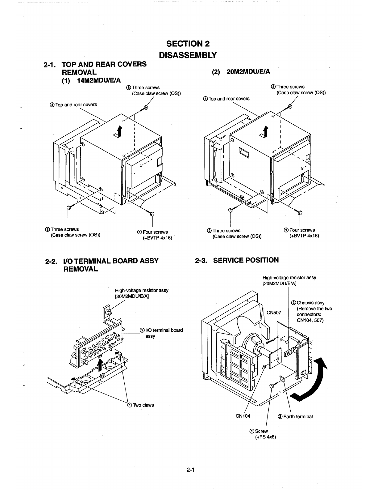
2-1.
AT
op
TOP
AND
REAR
REMOVAL
14M2MDU/E/A
(1)
d
and
rear
covers
COVERS
©
Three
(Case
screws
claw
s
SECTION
DISASSEMBLY
screw
(OS))
2.
©
(2)
Top
and
20M2MDU/E/A
covers
rear
@
|
Three
(Case
s
screws
claw
screw
(OS))
©
Three
(Case
2-2.
screws
claw
screw
(OS))
VOTERMINAL
REMOVAL
©
(1)
ASSY
©
Two
BOARD
High-voltage
[20M2MDU/E/A]
BVTP
resistor
/O
terminal
assy
ciaws
4x16)
assy
board
@
2-3.
Three
screws
(Case
claw
SERVICE
screw
(0S)
POSITION
@
Four
(+BVTP
High-voltage
[20M2MDU/E/A]
resistor
©
screws
4x16)
assy
Chassis
assy
(Remove
connectors:
CN104,
the
507)
two
©
Screw
(+PS
4x8)
©
Earth
terminal

2-4.
BOARDS
HAND
(1)
J
14M2MDU/E/A
Six
(+BVTP
@
Screw
(4BVTT
(©
Screw
(+BVTP
Screw
©
(+PS
REMOVAL
©
Two
screws
3x12)
(+PS
4x8)
3x8)
4x8)
screws
3x8)
@
Anode
cap
(8)
Chassis
Bottom
@
assy
assy
cabinet
© G block
@
Two
screws
(+BVTT
4x8)
©
Screw
(Ext
tooth
washer
(2)
20M2MDU/E/A
©
assy
QX
ーー
screw
Screw
(+BVTT
,
ひご
M4)
@
Two
screws
3x12)
(+BVTP
@
J board
G@)
Anode
4x8)
cap
Ad
ン
Six
screws
(+BVTP
3x12)
©
Screw
(Ext
tooth
washer
screw
M4)
screws
Two
(+BVTP
3x12) 一 一
@ J board
Two
Screws
(+BVTT
4x12)
2-2
Six
(+
screws
BVTP
3x12
x12)

2-5.
PICTURE
REMOVAL
(1)
14M2MDU/E/A
TUBE
AND X BOARD
@C
board
の
Sea
(+BVTT
4x8)
©)
Chassis
assy
@
Picture
@
@
Two
screws
(Ext
tooth
screw
@
Anode
@
Picture
@®
Tally
cushion
GĎ X board
(2)
20M2MDU/E/A
«Remove
Four
(Tapping
shield
tube
washer
M4)
cap
tube
Deflection
screws.
screw
yoke
5)
chassis
the
°
Two
assy
claws
and
:
bottom
© C board
‘
Cushion
cabinet
assy.
Chassis
.
(Refer
2-4.
to
assy
(3) G block
Screw
(+PS
4x8)
(2))
Screw
©
(+BVTP
Screw
(Ext
tooth
assy
A
3x8)
washer
Bottom
screw
Two
screws
(+BVTT
cabinet
M4)
4x8)
assy
screws
Two
⑥
(Ext
tooth
washer.
screw
M4)
@
Four
screws
(Tapping
Picture
©
Picture
Tally
(2 X board
screw
tube
tube
cushion
——S
5)
shield
©
Deflection
yoke
^
|
、
|
@
=
Two
<>
claws
2-3
Cushion
Screw
© G block
(+BVTT
4x8)
assy
Two
(+BVTT
screws
4x8)

+
©
NOTE:
@
REMOVAL
Short
the
anode
or
carbon
anode.
REMOVING
Tum
up
one
cated
by
the
OF
ANODE-CAP
circuit
the
cap
to
paint
on
PROCEDURES
side
of
the
arrow
@).
anode
of
the
metal
the
CRT,
rubber
cap
the
picture
chassis,
after
in
the
tube
and
CRT
shield
removing
direction
the
indi-
HOW
©
Don't
material!
@
Don't
caps!
A
material
in
the
©
Don't
The
ber.
TO
HANDLE
hurt
the
surface
press
the
rubber
fitting
called
rubber.
turn
the
foot
shatter-hook
terminal
AN
hardly
as
of
rubber
ANODE-CAP
of
anode-caps
not
to
hurt
|
shatter-hook
over
hardly!
will
stick
out
with
inside
of
terminal
or
hurt
the
shaped
anode-
is
built
rub-
@)
Using a thumb
tion
indicated
(©
When
anode
up
the
arrow
one
side
button,
rubber
cap
(©).
.
pull
up
by
the
of
the
the
anode-cap
and
the
rubber
arrow
(b).
rubber
pulling
cap
can
up
cap
firmly
Anode
is
separated
be
removed
it
in
the
in
the
button
by
direction
direc-
from
the
turning
of
the

SECTION
3
PREPARATIONS
3-1.
provided
is
set
This
used
be
can
that
panel
service
the
mode
menu
the
mode
service
the
mode
Service
(5)
items
titles.
by
etc.,
the
and
serial
the
adjustment
the
in
these
ROM
the
off
adjustment
the
with
of
I
keys
I
keys
display
the
of
are
guidance
the
values,
the
power
the
operation
Entering
1.
Service
(D
While
[DEGAUSS]
Service
©
While
[ENTER]
and
Service
2.
(1)
(2)
service
The
played
The
guidance,
left
the
This
107.
This
now
changing
the
to
turning
When
identical
of
names
is
is
stored
Range
(1)
(2)
(3)
(4)
(5)
method
displayed.
The
(6)
[+]:
power
[?]:
with
itself
(çi:
Ending
In
[DEGAUSS]
displayed.
is
In
[ENTER]
_
present
Writing
ROM
Problem
the
the
status
to
this
while
reading
standard
the
possesses.
in
service
the
the
of
case
keys
the
of
case
keys
the
(1)
|
for
switch
a
with
various
make
to
explained
is
switch
this
I
mode
displayed,
is
simultaneously.
mode
simultaneously.
Mode
largely
are
service
displayed.
number
data
RAM.
adjustment
or
data
displayed.
is
ROM.
display
error.
adjustment
PC
the
mode
service
simultaneously
service
simultaneously.
press
displayed,
is
I
Display
(4)
classified
items
The
right.
the
to
each
for
the
for
Adjustments
long
as
but
values
reading,
by
that
data
ROM,
the
in
Make
on.
is
case,
this
In
data
bus.
I,
mode
mode
SET-UP
service
adjustments.
in
[ENTER]
the
press
(3)
into
READ/WRITE
or
are
names
service
the
of
service
can
nothing
as
will
please
so
now
is
the
to
not
sure
image
an
microcomputer
the
that
the
press
the
while
press
II,
ADJUSTMENTS
front
the
on
The
below.
detail
[U/S]
the
(6)
types
16
|
displayed
items.
that
items
made
be
written
is
erased
be
careful.
be
displayed
(>)
cursor
off
turn
output
is
[ENTER]
mode
service
[U/S]
the
and
dis-
to
1-
are
by
by
is
is
the
and
and
Easy
ON/OFF
entering
once
If
power,
the
pressing
as
lights)
the
service
(No
function
Change
If
the
direction.
of
Change
The
forwarded
continuously
.
10.
of
switch
the
above
the
effective
of
items
Change
service
The
with
smaller
keys,
the
Reading
reading
When
[RESET]
in
shown
again.
once
previous
its
to
Writing
writing
When
[DEGAUSS]
in
shown
once
key
written,
Carrying
case
In
reason,
beginning
change
seconds
3
once
By
resetting
factory
and
data
the
been
has
or
etc.,
carried
of
the
the
easy
or
B
A,
the
the
as
long
mode
is
in
service
position
continuously
is
mode,
easy
method
This
screen
service
returned
are
with
pressed,
of
service
data
[1]
the
operation
of
service
data
once
key
guidance,
the
adjustment
The
state,
of
service
data
key
guidance,
the
again.
data,
all
but
FACTORY
out
adjustment
the
you
and
the
of
FACTORY
to
that
so
again
carried
be
will
resetting
available
destroyed,
factory
if
factory
out,
service
service
ON/OFF
switch
C
power
not
finished.
mode
service
the
of
display
the
used
is
area.
items
[ENTER]
the
the
data
made
is
When
key.
will
be
data
the
from
check
and
and
please
so
data
the
from
and
once
and
only
Not
please
so
data
pressing
keep
reading,
above
RESET
factory
the
pressing
out
will
time
the
at
if
or
setting
resetting
mode
after
mode
possible
is
front
the
on
turned
not
is
II)
mode
pressed
position
the
when
the
with
key.
operation
with
larger
continuously
repeated.
to
ROM
the
than
press
then
that
data
careful.
be
to
RAM
that
check
press
then
displayed
the
careful.
be
RESETTING
been
has
the
the
guidance
resetting
[RESET]
the
be
will
([*]
executed.
be
shipment
of
ROM
the
mentioned
executed.
is
having
once
by
panel
or
off
display
turning
when
moves
display
[MENU]
When
repeated.
be
will
[t
the
pressing
RAM,
the
READ
[RESET]
the
written
is
ROM,
the
WRITE
the
[DEGAUSS]
the
data
destroyed
[B/O]
guidance
READ
approximately
in
be
can
key
displayed
However,
from
been
has
later
turned
more
LED
(the
long
as
on
the
in
outside
is
key
key
a
key
]
press
display
return
will
press
display
will
for
at
key
carried
after
status)
as
in
factory
the
replaced,
has
on
on
as
in
V
and
is
and
the
the
is
key
the
be
some
the
will
out.
this,
case
been
3-1

11.
Carrying
Make
by
the
the
will
out
FACTORY
sure
to
make
making a copy
ROM.
If
you
beginning
change
ofthe
into
possible
of the
keep
FACTORY
approximately 3 seconds.
[DEGAUSS]
(1*]
will
copied.
of
the
the
standard
operation
again,
service
be
By
menu
but
mode
is
the
carrying
key
after
displayed
out
and
the
conditions,
carried
FACTORY
can
be
SETTING
adjustment
pressing
above
writing,
By
this,
as
status)
this
operation,
adjustment
so
out
once,
SET
set
to
1.
the
above
the
the
RESET
once
setting
and
values
please
it
cannot
FLAG
factory
data
when
[DEGAUSS]
WRITE
guidance
again
pressing
will
be
carried
the
data
the
selection
will
be
be
careful.
be
carried
(No.
107)
|
resetting
replacing
key
at
guidance
after
the
out
will
be
items
reset
to
If
this
out
in
the

1.
SERVICE
No. | SERVICE
1 | NOR
2
3
4 } NOR
5
6
7 | NOR
8
9
10
11
12
13
14
15
16
17
18 | U/S
19
20
21
22
23 | O/S
24,
25
26
27
28 | СОМРОМЕМТ
29
30
31
82 | NTSC
33
34
35
36
37
38 | PAL
39
40
41
42
43 | C/T1
44
45
46
47
48
49
50 | C/T2
51
52
53
54
|
50
60
DEF
DEF
DEF
D??
D??
MAP
I
ITEM
DEF
DEF
H
FREQUENCY
VIDEO
PHASE
V
SIZE
H
FREQUENCY
VIDEO
PHASE
V
SIZE
V
CENTER
H
SIZE
PIN
PHASE
PIN
AMP
LOWER
UPPER
SEXY
V
VBOW
LOWER V BOW
V
V
V
H
PIN
PIN
V
V
H
PIN
PIN
|
SUB
SUB
SUB
R-Y
BURST
CRYSTAL
PHASE
B-Y
CHROMA
R-Y
CRYSTAL
PHASE
B-Y
CHROMA
R-Y
3200K
BIAS
BIAS
BIAS
GAIN
GAIN
GAIN
3200K
BIAS
BIAS
BIAS
GAIN
PIN
PIN
LINEARITY
ANGLE
SIZE
<50>
SIZE
<60>
SIZE
PHASE
AMP
SIZE
<50>
SIZE
<60>
SIZE
PHASE
AMP
PHASE
CHROMA
CHROMA
LEVEL
GATE
PHASE
LEVEL
PHASE
LEVEL
SW
<RED>
<GREEN>
<BLUE>
<RED>
<GREEN>
<BLUE>
SW
<RED>
<GREEN>
<BLUE>
<RED>
AMP.
AMP
<NORMAL>
<SMPTE>
PULSE
Table
3-1-1
SERVICE
MAX|
STD]
255 | 85 | 55 | C/T2
255 | 1401
255 | 170 | 57 | C/T3
255 | 96 | 58
255 | 128}
255 | 170 | 60
255 | 128 | 61
255 | 100 | 62
255 | 1281
255 | 128 | 64 | USER
255 | 128]
255 | 1281
255 | 128 | 67
255 | 128 | 68
63 | 35 1 69
63 | 20 | 70
63 | 20 | 71 | W/B
255 | 140]
255 | 140]
255 | 128 | 74 | OTHER
255 | 128}
255 | 100]
255 | 190 | 77
255 | 190 | 78
255 | 128 | 79
255 | 1281
255 | 150 | 81
255 | 130 | 82
255 | 182 | 83
255 | 170 | 84
255 | 163]
WIDTH | 255 | 52 | 86
255 | 59 | 87
255:
255 | 162 | 89 | SYSTEM
255 | 98 | 90
255 | 98 | 91
255 | 82 | 92
255 | 110 | 93
255 | 122 | 94
255 | 109 | 95
255 | 121 | 96
1
1023]
600]
1023|
300 | 99
1023]
300 | 100
1023)
800 | 101
1023;
700 ; 102
1023)
500]
1
1023|
700 | 105
1023]
300 | 106
1023!
200 | 107
1023)
800
MAP I (1)
No.|
SERVICE
D??
56
D??
59
63
65
66
72
73
75
76
80
85
80 | 88
0
97
98
103
O
1104
C/T
X
Signify
destination.)
Refer
MAP I (2).
ITEM
GAIN
GAIN
3200K
BIAS
BIAS
BIAS
GAIN
GAIN
GAIN
ORG|
3200K
BIAS
BIAS
BIAS
GAIN
GAIN
GAIN
SUB
SUB
SUB
LANDING
SPLIT
DEGAUSS
V
H
O/S H BLANKING
O/S H BLANKING
V
O/S
O/S
V
O/S
O/S
HP
HP
358
CAPTION
COMPONENT
NTSC
CHROMA
COLOR
COLOR
USER
LANGUAGE
RGB
RGB
AGING
REMOTE
MODEL
COLOR
COLOR
COLOR
REMOTE
FACTORY
(The
to
the
<GREEN>
<BLUE>
SW
<RED>
<GREEN>
<BLUE>
<RED>
<GREEN>
<BLUE>
SW
<RED>
<GREEN>
<BLUE>
<RED>
<GREEN>
<BLUE>
CON
<NORMAL>
CON
<0/S>
BRIGHT
PHASE
DELAY
HOLD
BLANKING
BLANKING
UPPER V BLK
LOWER V BLK
BLANKING
UPPER V BLK
LOWER V BLK
POSITION
WIDTH
TRAP
FILTER
VISION
SETUP
SET
SYSTEM
TEMPERATURE
PRESET
MODE
MODE
MODE
MODE
TEMP
TEMP
TEMP
ADDRESS
SET
setting
“Table
|
<50>
<60>
LEVEL
LEVEL
UP
A
B
DISP
DISP
DISP
FLAG
is
3-1-2
START
END
<50>
<50>
<60>
<60>
DISPLAY
KEY
1
2
3
vary
with
the
SERVICE
MAX|
STD
1023]
700
1023)
500
1
0
1023!
500
1023)
300
1023]
400
1023]
700
1023)
700
1023|
700
1
0
1023}
600
1023}
300
1023]
300
1023|
800
1023]
700
1023;
500
255 | 178
255 | 178
255 | 69
255 | 64
2551
0
127
0
255 | 128
255 | 73
255 i 73
255|
76
255 | 82
255 | 14
255 | 177
255 | 161
255 | 19
255 | 230
255 | 145
255 | 148
1
0
7
0
3
e
1
se
1
0
3
0
3
0
1
0
7
0
3
1
3
1
1
0
1
0
31
x
1271
65
127 | 56
127 | 93
63
1
1
0

2.
SERVICE
MAP
Model
PVM-20M2MDU
PVM-20M2MDE
PVM-20M2MDA
PVM-14M2MDU
PVM-14M2MDE
PVM-14M2MDA
И
Name
1
W/B
2
W/B
3
W/B
4
W/B
5
W/B
6
W/B
7
W/B
8
W/B
9
W/B
10 | W/B
11. | W/B
12 | W/B
13 | LINEA
14 | LINE A BRIGHT
15 | LINE B CONTRAST
16 | LINE B BRIGHT
17 | АСВ А CONTRAST
18
RGB A BRIGHT
19
RGB B CONTRAST
20 | RGB B BRIGHT
Table
3-1-2
SERVICE
Component
NTSC
R-Y
NTSC
B-Y
PAL
R-Y 255 | 176 | 180
PAL
B-Y
COMPONENT
COMPONENT A B-Y
COMPONENT
COMPONENT
RGB A R-Y
RGB A B-Y
RGB
BR-Y
RGB B B-Y
CONTRAST
level
1 1
2 0
2
1 1
2
2
Table
3-1-3
SERVICE
SERVICE
ITEM
A
R-Y
B
R-Y
B
B-Y 255
MAP I (2)
NTSC
MAP
Set-up
level
0
0
0
I
MAX
255 | 174 | 171
255 | 161 | 158
255
255
255 | 156 | 178
255
255 | 114 | 127
255 | 131 | 134
255 | 114 | 127
255 | 131 | 134
100
100
100
100
100
100
100
100
inch
160
161
161
156 178
Mode!
0
2
3
4
6
7
STD
l20inch
158
174
174
50
50
50 50
50
50
50
50
50
50
50
50
50
50
50
50

3-2.
PREPARATION
*
Supply
composite
pply
in
Table
Signal
Composite | ¿ceyT
video
p p
3-2.
PAL
BETÃO | 75%
Component
SMPTE | 75%
Voice/sound
(2).
INITIALIZATION
video
or
component
Table
3-2
Details
of
signal
100%
white
75%
white
100%
white
75%
white
100%
white Y 0.7V
white Y 0.525V
75%color
B-Y,
R-Y
(P-P
for
this
only)
100%
white
white
7596color
B-Y,
R-Y
(P-P
for
this
only)
-5dBs
signals
as
る
[Standard
0.714V
0.536V
0.7V
0.525V
item
Y
Y
item
0.7V
0.7V
0.525V
0.525V
0.436Vrms
shown
P-W
3-3.
1.
Write
at
Table
level
.
.
.
WRITING
model
the
location
3-3.
PVM-20M2MDU
PVM-20M2MDE
PVM-20M2MDA
PVM-14M2MDU
PVM-14M2MDE
PVM-14M2MDA
Write
the
following
tion
of
No.103
COLOR
Write
of
COLOR
Write
of
COLOR
Standard
Unless
adjustment
the
No.104
the
No.105
otherwise
TEMP
following
TEMP
following
TEMP
inspection
data
of
Model
COLOR
COLOR
COLOR
under
MODEL
on
respective
No.102
Table
data
DISP
1
65
data
in
TEMP
DISP
2
56
data
in
TEMP
DISP
3
93
state
specified
the
following
MODEL
3-3
in
the
TEMP
the
DISP
the
DISP
DATA
models
in
in
accordance
Model
data
0
12
ϱ
Bb
“NO
service
mode
DISP
1.
service
mode
2.
service
mode
3.
in
this
conditions:
the
service
at
at
the
at
the
manual,
mode
with
the
loca-
location
location
make
*
Jn
the
Example:
*
Before
service
is
this
chapter,
service
turning
mode,
turned
mode.
off
[___]
off
write
before
indicates
the
power
the
adjustment
writing,
adjusted
the
after
data.
data
control
items
adjustment
When
the
will
all
in
the
power
be
lost.
in
APERTURE
BRIGHT
CHROMA
PHASE
CONTRAST
©
VOLUME
MIN
50%
50%
50%
80%
50%
(TumFLAT
(Center
(Center
(Center
(Center
click)
click)
click)
click)
fully
counterclockwise.)

3-4.
PICTURE
OUTPUT
1.
2.
3-5.
-
=
AC
input
voltage
1.
Input
VIDEO
terminals
Set
PVM-20M2MDU
PVM-14M2MDU
PVM-20M2MDE
PVM-20M2MDA
PVM-14M2MDE
PVM-14M2MDA
the
sliduck
on
Group
LANDING
I.
CONT...
BRT
2.
Roughly
3.
Switch
the
4,
Adjust
center
(Fig.
5.
Switch
(Figs.3-1,
6.
Bring
the
screen
7.
If
tern
deflection
8.
Switch
color.
9.
Switch
color.
10.
When
standard,
11.
Switch
12.
When
it
MAX
...
Conspicuous
adjust
the
rotary
color
into
the
purity
of
the
3-1)
to B only, R only,
3-2,
the
deflection
deflection
will
be
the
deflection
shown
yoke
the
single
(Fig.3-6)
the
single
(Fig.3-9)
two
colors
and
to
an
the
deflection
with
the
fixture.
ina
setting
signals
and
AUDIO
the
connector
AC
voltage
of
models
Table
panel.
as
3-4
ADJUSTMENT
position
the
white
balance,
SW
of
the
single
green
only.
knob
so
that
screen.
yoke
green.
in
repeat
all-white
Make R and B almost
and G only
and
3-3)
yoke
gradually
so
that R and B on
(Fig.3-2 n Fig.
yoke
comes
Fig.3-4
backward.
will
(Fig.3-4
color
switch
color
switch
are
mixed,
operations 6 and
signal
yoke
position
signals
shown
(Same
(Same
G2, and
color
the
green
forward
appear.
n
to B and
to R and
set
the
and
check
is
to
respective.
in
Table
3-4.
Voltage
AC
120+3V
as
above)
220+3V
AC
as
above)
convergence.
switch
to
will
come
identical.
and
verify
forward
3-3)
mixed
and
both
sides
too
much,
If
so,
move
Fig.3-3)
verify
the
verify
the
color
7.
the
uniformity.
determined,
|
change
to
the
each.
adjust
of
the
the
pat-
the
single
single
as
the
fasten
RİGİBİ—
Fig.3-2
GÅ
Fig.3-5
sénèel—l
Fig.3-8
|
Purity
=
+
Figai | 7)
i
BAR | —+
FPA
14inch
control
da
Purity
Deflection
14inch
SSR | nA
PSI
A
G
Fig.3-3
ーー
B
Fig.3-6
в
Fig.3-9
Fig.3-11
yoke
Fig.3-12
e
— | BlGaR
=
.
|+
|
В
сб
20inch
-
control
Purity
Te
20inch
Fig.3-4
вое
Fig.3-7
Абв
Fig.3-10
/
レッ ー Purity
Deflection
yoke
3-6

3-6.
CONVERGENCE
1.
Input a dot
CONT.....
BRT.........
Align
the
screen
When
adjust
CENT
.
Align
the
the
screen
After
V-STAT
V-STAT
While
vertical
pattern
Conspicuous
MIN
horizontal
with
the
H-START
H-CENT
H-STAT.
VR.)
keeping
convergence.
vertical
with
adjustment,
Mg
knob
is
(H-STAT
location
the
the
NI
ADJUSTMENT
signal.
position
R,
G,
and B dots
VR.
changed
V-STAT
angles A and B equal 1 =
~
after
will
of
R,
Mg.
paint-lock
at
the
H-STAT
change
G,
by
and B in
(Fig.3-13,
the
(1)
center
of
the
adjustment,
means
the
3-14)
knob.
I°),
of
center
align
re-
H-
the
of
4,
For
that
the G dot.
x
»
s,
`
x
<
x.
a,
ヽ
Change
degree
to
5.
For
that
the G dot.
~
Do
C
HMC,
they
will
6-pole
the
of
control
VMC,
they
will
not
change.
use
the
be
symmetrical
'
>
magnet
opening
the
BMC
the
HMC.
use
the
be
BMC
Mg
to
horizontally
e
è
2
+
A
΄
ァ
B
Mg
Fig.
3-15
MBC
Mg
to
symmetrical
(Top)
adjust
the R and B dots
with
Control
the
that
A=A'.
when
moving
adjust
the R and B dots
vertically
R
with
G
respect
BMC
Mg
Maintain
the
Mg.
respect
B
so
to
so
ЕЁ
so
to
Fig.
If
the A and B knobs
focus
may
deteriorate,
effects
may
occur.
AD)
Fig.
3-13
3-14
Good
are
beam
Y
Bad
Y
example
not
symmetrical
striking
example
or
(J # I’),
other
the
adverse
For
VMC
knob
without
opening
BMC
Repeat
The
ment,
7.
Paint-lock
6-pole
Mg
control,
to
the
right
changing
degree
Mg.
adjustments
above
adjustment
check
the
the
knobs
turn
or
left
ther
of
the
2.
may
landing
after
Make
that
same
Fig.
3-16
to
5.
affect
the
again.
adjustment.
adjustment
the
gap
at
the
landing,
so
willbe
top
and
so
after
the
botton.
adjust-
|

3-7.
DEFLECTION
ADJUSTMENT
1.
If
there
axis
of
the
direction
the
entire
(1)
Reverse
misconvergence
Move
downward.
Re
Glo-
B
o”
(3)
Pattern
deflection
Move
yoke
viewed
screen.
| L | | L |
R
is
nonconvergence
the
screen,
of
the
CRT
screen
cross
pattern
the
deflection
BGR
오우
\
o
0
る
らら
RGB
Fig.
3-17
of
left-sided
yoke
the
deflcetion
to
the
right
ЕЮ.
the
3-19
when
CRT
BR
|
from
B
turn
arrow
yoke
„o
-©
-©
YOKE
on
the
neck
to
hold
within
(2)
Regular
Move
|
upward.
|B
|G
R
(4)
2
NECK
both
sides
of
the
the
nonconvergence
the
tolerance.
cross
pattem
the
deflection
o
Bİo..
Gjo-:
R
o
Fig.
Pattern
deflection
Move
the
yoke
to
viewed
screen.
L
B
R
Fig.
T
ROTATION
of
the X or
deflection
misconvergence
yoke
RGB
“oo
\
-©
o
=--O
ms
Le
dös
BGR
3-18
of
right-sided
yoke
deflection
the
left
when
from
the
CRT
L
А
3-20
yoke
В
Y
in
for
|
UNU
3.
The
the
Rie
G|O
B
©“ n
G
(G)
ooo
R
B B
following
neck,
(Pigs.3-23,
“oo
|
о
る
らら
RGB
o
G o RB
(G)
©
G)
©
(6)
ORB
Go
patterns
-®
Zo
“O
(G) G
ooo
R
cannot
3-24,
B
G
R
Fig.
Fig.
Fig.
and
3-25)
*
Gun
The
beams
both
3-23
*
HCR
The
G
than
both
3-24
*
VCR
The
G
than
both
3-25
be
corrected
rotatuon
X-axis
are
sides.
Large(Small)
horizontal
raster
is
that
sides
Large(Small)
vertical
rasier
is
that
sides
by
turning
and
Y-axis
distorted
wider(narrower)
of
the
of
wider(narrower)
of
the
of
portion
RB
the
screen.
portion
RB
the
screen.
on
of
raster
of
the
raster
the
on
on
2.
Insert
the
funnel
to
wedge
lock
between
the
deflection
1
zone
Fig.
3-21
the
Fig.
3-22
deflection
yoke.
(Fig.3-22)
yoke
and
CRT
3-8

CONVERGENCE
YCH
ADJUSTMENT
XCV
(2)
|
3-9.
Input a 525
Connect
Measure
Make
PORT
waveform
G2
ADJUSTMENT
monoscope
the
probe
of
the
lowest
adjustment
will
be
with
1.35
signal.
the
oscilloscope
reference
SCREEN
V+0.05
pulse
VR
V,
of
to
the
so
TP403
three.
that
the
on
the A board.
left
end
of
the
|
Fig.
3-26
Note
1.
When
:
for
perfect
14
inch
Models
Input a cross-hatch
Make
adjustment
of
the
deflection
When
the
nonconvergence
included
compensator
(Fig.3-26)
20
inch
inthe
Models
Convergence
and
compensator
adjustment
adjustment.
signal.
with
the
yoke
to
horizontal
into
the
deflection
compensation
is
insufficient,
TLV,
YCH
minimize
convergence,
nonconvergence.
of
the
TILT
yoke
|
VR,coil,
use
VR,
insert
for
permalloy
and
XCV
component
the
adjustment.
coils
is
TLH
1.35V+
0.05V
(V
synchronization)
The
waveform
as
shown
Adjust
it
will
be
Fig.
3-27
the
1.35V+
᾿
on
left
GND
is a rectangle
the
left.
corner
so
that
0.05V.
Input a cross-hatch
2.
Make
adjustment
to
minimize
.
When
the
nonconvergence
included
compensator
(Fig.3-26)
in
signal.
with
the
XCV
nonconvergence.
of
the
vertical
into
the
deflection
convergence,
coil of
the
the
TILT
yoke
deflection
component
insert
the
for
adjustment.
yoke
is
TLV
3-9

3-10.
WHITE
Input a 525
with
no
.
Set
as
CONT
BRT
Adjust
tone
gray
0
and 5 IRE — Cut
10
Input
525
Set
CONT
A
Adjust
nance
7.
Press
MENU
.
Select
Set
Put
the
9.
10.
Adjust
of
[CITI
11.
Switch
12.
Adjust
of
13.
Repeat
is
complete,
14.
Press
MENU
15.
Select
16.
Adjust
as
adjustments
17.
The
adjustment
data.
18.
Press
19.
Select
20.
Adjust
as
adjustments
21.
The
adjustment
data.
NOTE : Set
BALANCE
monoscope
burst.)
follows:
0%
50%
scale
will
be
IRE > Slight
all-white
VR
the
all-white
will
be 3 NIT.
6500K.
[3200K
unit into
to
the
6500K
the
all-white
to
the
adjustment
5600K.
[C712
MENU
9300K.
[C/T3
cut-off
Fix
as
BIAS
GAIN
<Standard
COL
COL
COL
(COMPOSITE
to
80%.
and
select
sw]
to
“0”
the
standard
BIAS] . (Refer
standard
.
(Refer
(10,
and
then
and
select
5600K
BIAS]
10.
to
is
complete,
and
select
9300K
BIAS]
10.
to
is
complete,
to
follows : <GREEN>
GREEN
GREEN...
Values>
TEMP
TEMP
TEMP
signal.
in
the
service
as
follows:
off
glow
luminance
COL
for
both
service
mode.
values
to
NOTE:)
signal
luminance
values
to
NOTE:)
11,
and
write
the
COL
[C/T2
5600K
13..
and
COL
[C/T3
9300K GAIN]
13..
(Refer
and
3NIT.
...
“300”
700”
1...
6500K + 8MPCD
2...
5600K + 8MPCD
3...
9300K + 8MPCD
ADJUSTMENT
(Input
from
LINE A or
mode
so
signal
without
so
that
the
screen
TEMP
SELECT.
T1,
T2
and
with
<RED>
with
<RED>
12)
adjustment
TEMP
GAIN]
then
TEMP
to
then
to
100
until
the
SELECT.
in
the
write
the
SELECT.
in
the
NOTE:)
write
the
and
and
data.
same
same
that
the
20-
burst).
lumi-
T3.
<BLUE>
IRE.
<BLUE>
adjustment
manner
adjustment
manner
adjustment
B
3-11.
1.
Input a 525
2.
Set
as
CONT....
BRT
Select
>
Adjust
IRE
3-12.
1.
20
inch
1.
Input a 525
Adjust
“30”
the
center
3.
Switch
After
knob.
.
14
1.
Inputa
Make
dots
C
board.
3.
Check
of a digital
Change
ring
SUB
BRT
monoscope
follows
:
Min
....
50%
is
cut
off.
FOCUS
Models
monoscope
the
focus
at
of
the
to
an
all-white
focus
adjustment,
inch
Models
525
dot
adjustment
on
both
sides
that
the
resolution
monoscope
an
all-white
is
unconspicuous
O
Make
the
ADJUSTMENT
signal.
in
the
service
so
that
10
ADJUSTMENT
signal.
to
optimize
screen
with
signal
paint-lock
signal.
so
that the
are
not
separated
is
more
signal.
signal,
by
means.
EN
Just
X7
Focus
|
ン
NÍ
adjustment
dots
are
Fig.
so
not
separated
3-28
mode.
IRE
the
focus
FOCUS
and
check
the
center
than
and
check
©
that
the
glows
on
PACK
the
FOCUS
dot
and
with
using
600
that
both
slightly
the
lines
and
characters
VR.
uniformity.
PACK
center
of
RV707
by
means
the
magenta
0
VR
the
on
3-10

SECTION
4
SAFETY
When
the
parts
(with
abd , mark
shown
below
are
replaced,
items
4-1
and
4-2
shown
4
В!536
R551, R506,
R1536,
D501, D533,
When
the
following
IC600,
IC602,
Confirmation
1.
Input
120
2.
Input a monoscope
and
BRIGHT.
.
Check
4-1.
CONFIRAMATION
Standard : Less
Check
Condition
Note:
Input
Controls : BRT & CONT + Normal
Use
distortion
signal : Monoscope
R519,
R1560, R1537,
Q500,
D610,
procedure
VAC.
that
the
voltage
than]
Input
NF
below.
R518,
0511,
parts
are
C615,
C631, C621,
signal,
of
15.7
VDC(CN605
voltage : 130
Power
factor
confirm
R516,
C549,
C512,
10500,
replaced,
and
the
CN605
Supply
is
3%
on
the
the
matters
R515, R508,
C513,
απά
check
C632,
minimize
(D
OF
+B
pin
VAC
or
or
less.
circuit
described
C523,
IC507
the
+B
and
T603
CONTRAST
pin
is
115.7
MAXIMUM
@)
make
RELATED
diagram)
in
R517,
C592,
voltage:
VDC.
sure
that
ADJUSTMENT
4-2,
CONFIRAMATION
CIRCUIT
Check
Condition
Input
signal : White
Controls : BRT & Cont + Max. & Min.
4-2-1.
a)
Hold-Down
Adjust
600+50LA
external
127.0
VDC
down
circuit
Input
Signal : White
Adjust
b)
(14
inch)
power
(14
inch))to
works.
Input
Signal : Dot
4-2-2.
Hold-Down
the
beam
(14
DC
power
(14
the
beam
with
supply
Input
&Dot
inch)
supply
inch))to
works.
current
the
pin © of
(less
than
the
point
voltage : 130
Circuit
current
with
just
Circuit
FBT)
Check
item : Check
a)
Adjust
600+50LA
external
point
Input
b)
Adjust
(14
power
(14
works.
Input
the
DC
just
Signal : White
the
inch)
supply
inch))to
Signal : Dot
of
110.0VDC
beam
(14
inch)
power
before
the
beam
current
with
the
(less
the
point
pin
current
with
supply
hold-down
pin
6)
than
just
(+B)
to
the
pin @ of
(less
the
point
to
100+201A
CN605
131.0
VDC
before
ÚĎ
of
IC500
to
the
(less
to
100£20,,A
of
IC500
143.0
VDC
before
OF
VAC
1000+50p1A
than
the
(3rd
1000+50LA
pin
than
circuit
the
HOLD-DOWN
(20
CN605
130.0
VDC
(20
just
before
the
(20
inch),
804201A
with
the
external
(20
inch),
127.0
hold-down
Wire
voltage
voltage : more
(20
@®
of
IC500
141.0
VDC)to
works.
(20
inch),
with
the
external
(20
inch),
141.0
hold-down
inch),
with
the
inch),
hold-
DC
VDC
circuit
of
than
inch),
with
the
the
80t20uA
DC
VDC
circuit

G
board
A
board
(A
ee
a
side)
Zope
И
SE
THE
SE
o
A
board
ο
coma
(B
ide)
s
dijital
multimeter
 Loading...