

Sony Trinitron PVM-14L3, Trinitron PVM-14L4, Trinitron PVM-20L4 Operating Instructions Manual
PVM-14L4/PVM-20L4/PVM-14L3
4-086-475-16 (1)
Trinitron
®
Color Video Monitor
Operating Instructions
Mode d’emploi
Manual de instrucciones
Bedienungsanleitung
Istruzioni per l’uso
使用说明书
GB
FR
ES
FR
DE
IT
CS
PVM-14L4
PVM-20L4
PVM-14L3
2001 Sony Corporation

English
WARNING
To prevent fire or shock hazard, do not
expose the unit to rain or moisture.
Dangerously high voltage are present
inside the unit.
Do not open the cabinet. Refer servicing
to qualified personnel only.
In the event of a malfunction or when maintenance is
necessary, consult an authorized Sony dealer.
For the customers in Europe
This product with the CE marking complies with both
the EMC Directive (89/336/EEC) and the Low Voltage
Directive (73/23/EEC) issued by the Commission of
the European Community.
Compliance with these directives implies conformity to
the following European standards:
• EN60950: Product Safety
• EN55103-1: Electromagnetic Interference (Emission)
• EN55103-2: Electromagnetic Susceptibility
(Immunity)
This product is intended for use in the following
Electromagnetic Environment(s):
E1 (residential), E2 (commercial and light industrial),
E3 (urban outdoors) and E4 (controlled EMC
environment, ex. TV studio).
These products are designed for operation in the
environments E1 to E4. During EMC stress, the
performance (evaluated according to ITU/R 562-3 and
ITU/R 500-4) may degrade as shown in Table 1.
Without the EMC stress, all performance will recover to
full function.
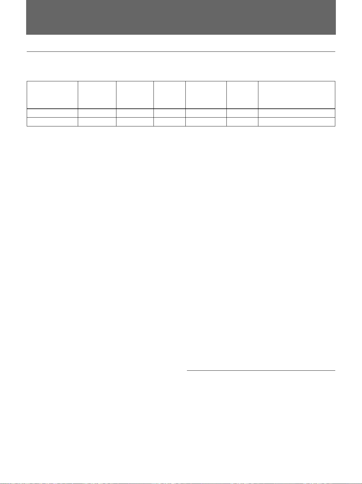
Table 1
Level
4.0 – 4.5
4.0
4.5
PVM-14L4/14L3
(14-inch Monitors)
PVM-20L4
(20-inch Monitor)
Frequency
155 – 200 MHz 4.5
259 – 376 MHz
306 – 353 MHz
259 – 289 MHz/
378 – 418 MHz/
489 – 520 MHz/
535 – 598 MHz
ATTENTION – When the product is installed in
a rack:
a) Elevated operating ambient temperature
If installed in a closed or multi-unit rack assembly,
the operating ambient temperature of the rack
environment may be greater than room ambient.
Therefore, consideration should be given to
installing the equipment in an environment
compatible with the manufacture’s maximum rated
ambient temperature (Tmra: 0°C to 35°C).
b) Reduced air flow
Installation of the equipment in a rack should be
such that the amount of air flow required for safe
operation of the equipment is not compromised.
c) Mechanical loading
Mounting of the equipment in the rack should be
such that a hazardous condition is not achieved
due to uneven mechanical loading.
d) Circuit overloading
Consideration should be given to the connection of
the equipment to the supply circuit and the effect
that overloading of circuits might have on
overcurrent protection and supply wiring.
Appropriate consideration of equipment nameplate
ratings should be used when addressing this
concern.
e) Reliable earthing
Reliable earthing of rack-mounted equipment
should be maintained. Particular attention should
be given to supply connections other than direct
connections to the branch circuit (e.g., use of power
strips).
f) Gap keeping
Upper and lower gap of rack-mounted equipment
should be kept 44 mm.
2 (GB)
Precaution
On safety
•Operate the unit only with a power source as
specified in “Specifications” section.
• The nameplate indicating operating voltage, power
consumption, etc., is located at the rear.
• Should any solid object or liquid fall into the cabinet,
unplug the unit and have it checked by qualified
personnel before operating it any further.
•Do not drop or place heavy objects on the power
cord. If the power cord is damaged, turn off the
power immediately. It is dangerous to use the unit
with a damaged power cord.
•Unplug the unit from the wall outlet if it is not to be
used for several days or more.
•Disconnect the power cord from the AC outlet by
grasping the plug, not by pulling the cord.
• The socket-outlet shall be installed near the
equipment and shall be easily accessible.
On installation
On cleaning
To keep the unit looking brand-new, periodically clean
it with a mild detergent solution. Never use strong
solvents such as thinner or benzine, or abrasive
cleansers since they will damage the cabinet. As a
safety precaution, unplug the unit before cleaning it.
On repacking
Do not throw away the carton and packing materials.
They make an ideal container which to transport the
unit. When shipping the unit to another location,
repack it as illustrated on the carton.
If you have any questions about this unit, contact your
authorized Sony dealer.
GB
English
•Allow adequate air circulation to prevent internal
heat build-up.
Do not place the unit on surfaces (rugs, blankets,
etc.) or near materials (curtains, draperies) that may
block the ventilation holes.
•Do not install the unit in a location near heat sources
such as radiators or air ducts, or in a place subject to
direct sunlight, excessive dust, mechanical vibration
or shock.
On cleaning of the CRT surface
(PVM-14L4/20L4 only)
• The surface of the CRT has an optional PET film
treatment.
Clean the CRT surface using the following method
to avoid damaging the surface.
•Clean the CRT with a soft cloth.
When the CRT is dirtied with oily hands or
fingerprints, clean it with a soft cloth moistened with
a mild detergent solution.
•Never use abrasive cleansers, alkaline soap, strong
solvents such as alcohol, thinner or benzine, since
they will damage the surface.
•Do not rub the surface of the CRT with a solid object
or hit it.
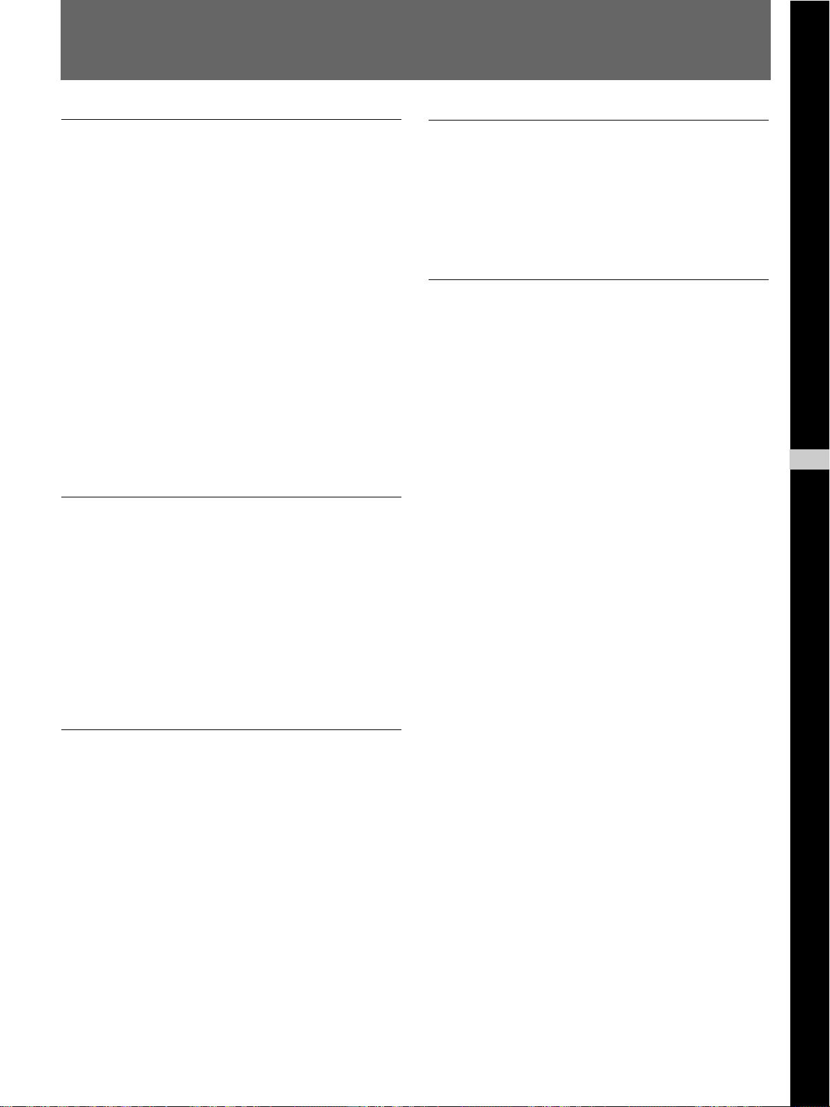
3 (GB)

Table of contents
Precaution ................................................................. 3 (GB)
Features..................................................................... 5 (GB)
Connections.............................................................. 7 (GB)
How to Connect the AC Power Cord............................ 7 (GB)
How to Connect a Cable to a BNC Connector.............. 7 (GB)
Location and Function of Parts and Controls ....... 8 (GB)
Control Panels ............................................................... 8 (GB)
Rear Panel ................................................................... 10 (GB)
Selecting the Menu Language............................... 13 (GB)
Using the Menu....................................................... 14 (GB)
Display List ............................................................. 15 (GB)
STATUS Menu......................................................... 17 (GB)
COLOR TEMP/BAL Menu....................................... 17 (GB)
USER CONTROL 1/2, 2/2 Menu ............................. 18 (GB)
USER CONFIG 1/2, 2/2 Menu ................................. 19 (GB)
REMOTE 1/2 PARALLEL Menu.............................. 20 (GB)
REMOTE 2/2 SERIAL Menu.................................... 20 (GB)
OPTION CONFIG Menu .......................................... 21 (GB)
KEY PROTECT Menu.............................................. 22 (GB)
Troubleshooting ..................................................... 22 (GB)
Specifications ......................................................... 23 (GB)
The explanation given in this manual can be applied to the
following models unless noted otherwise.
When explanation differs among models, this is clearly
indicated in this manual.
•PVM-14L4 (14-inch monitor)
•PVM-20L4 (20-inch monitor)
•PVM-14L3 (14-inch monitor)
Illustrations of the video monitor are of the PVM-14L4.
4 (GB)

Features
Picture
HR (High Resolution) Trinitron1) picture tube
for PVM-14L4 and PVM-20L4
HR Trinitron tube provides a high resolution picture.
Horizontal resolution is more than 800 TV lines (4:3)
or 600 TV lines (16:9) at the center of the picture.
1)
Trinitron
for PVM-14L3
Trinitron tube provides a high resolution picture.
Horizontal resolution is more than 600 TV lines (4:3)
at the center of the picture.
Comb filter
When NTSC and PAL video signals are received, a
comb filter activates to make more accurate Y/C
separation. This contributes to less of a decrease in
resolution, cross color and cross luminance
phenomena.
Beam current feedback circuit
The built-in beam current feedback circuit assures
stable white balance.
picture tube
Input
Analog RGB/component input connectors
Analog RGB or component (Y, R-Y and B-Y) signals
from video equipment can be input through these
connectors. Select either of two signals using the RGB/
COMP input switch button.
Y/C input connectors (S-input connector)
The video signal, split into the luminance signal (Y)
and the chrominance signal (C), can be input through
this connector, eliminating the interference between
the two signals, which tends to occur in a composite
video signal, ensuring video quality.
Expandable input capability
You can easily expand the input capability by
installing an input adaptor (not supplied) in the input
option slot in the rear of the monitor.
External sync input
When the EXT SYNC selector is in the on position,
the monitor can be operated on the sync signal
supplied from an external sync generator.
Four color system available
The monitor can display NTSC, PAL, SECAM and
NTSC4.43 signals. The appropriate color system is
selected automatically.
Auto chroma phase function
The chroma and phase of the decoder are
automatically adjusted with the auto chroma phase
function.
Blue only mode
In the blue only mode, an apparent monochrome
display is obtained with all three of the R/G/B
cathodes driven with a blue signal. This facilitates
color saturation and phase adjustments and observation
of VCR noise.
Automatic termination (connector with
mark only)
The input connector is terminated at 75 ohms inside
when nothing has been connected to the output
connector. If a cable is connected to the output
connector, the internal terminal is automatically
released and the signals input to the input connector
are output to the output connector (loop-through).
Functions
Underscan mode
The signal normally scanned outside of the screen can
be monitored in the underscan mode.
Note
When the monitor is in the underscan mode, the dark
RGB scanning lines may appear on the top edge of the
screen. These are caused by an internal test signal,
rather than the input signal.
.........................................................................................................................................................................................................
1) “Trinitron” is a registered trademark of Sony Corporation.
5 (GB)

Features
Horizontal/vertical delay mode
The horizontal and vertical sync signals can be
monitored simultaneously in the H/V delay mode.
Auto/manual degaussing
The CRT is automatically degaussed when the power
is turned on. You can manually degauss the CRT by
pressing the DEGAUSS button.
In the menu, you can set the time to automatically
degauss after turning on the power.
Note
The DEGAUSS button is disabled when the screen
menu is being displayed.
To manually degauss the CRT, exit the screen menu
by pressing the MENU button.
On-screen menus
You can set color temperature, CHROMA set up, and
other settings by using the on-screen menus.
EIA 19-inch rack mount bracket available
The monitor may be mounted on an EIA-standard 19inch rack, using an optional mounting bracket MB-521
(for PVM-14L3 and PVM-14L4) or slide rail SLR-104
(for PVM-20L4).
For details on mounting the monitor on the rack, refer to the
Operating Instructions of the mounting bracket or slide rail.
6 (GB)
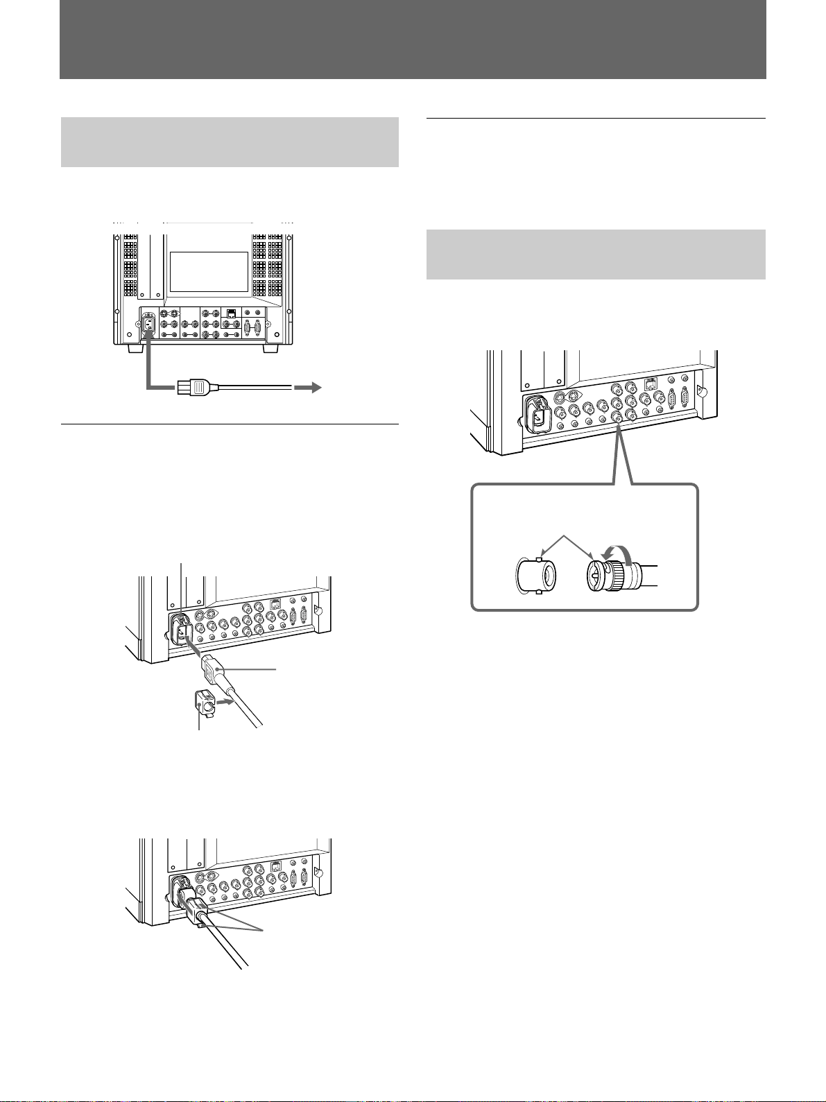
Connections
How to Connect the AC Power
Cord
Connect the AC power cord (supplied) to the AC IN
socket on the rear panel and to a wall outlet.
to AC IN
to a wall outlet
To connect an AC power cord securely
with AC plug holder
1 Plug the power cord into the AC IN socket. Then,
attach the AC plug holder (supplied) on top of the
AC power cord.
To remove the AC power cord
Pull out the AC plug holder while pressing the lock
levers.
How to Connect a Cable to a
BNC Connector
Connect a coaxial cable with the BNC plugs to the
BNC connectors on the rear panel as illustrated below.
Insert the BNC plug into the connector on
the rear panel, matching the slit and pin,
and turn the BNC plug clockwise to
secure the connection.
AC IN socket
AC power plug
AC plug holder
2 Slide the AC plug holder over the cord until it
locks.
Lock levers
7 (GB)
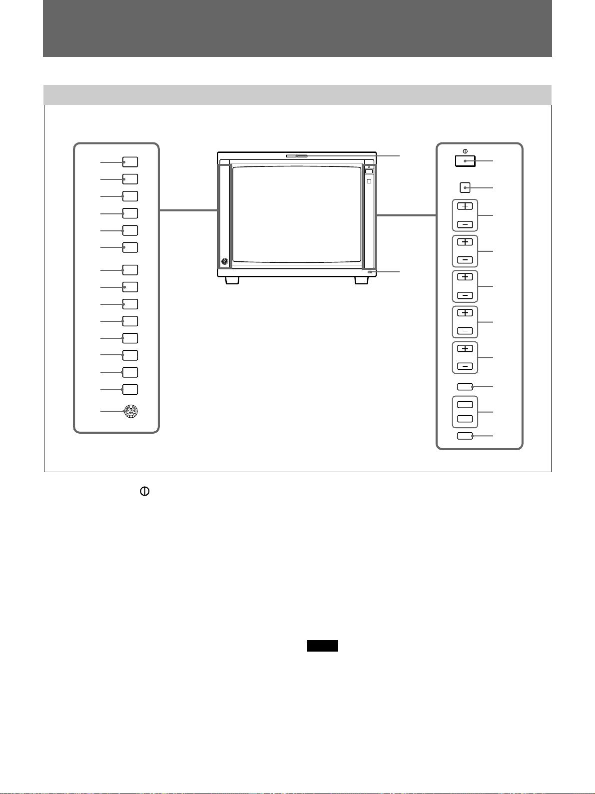
Location and Function of Parts and Controls
Location and Function of Parts and Controls
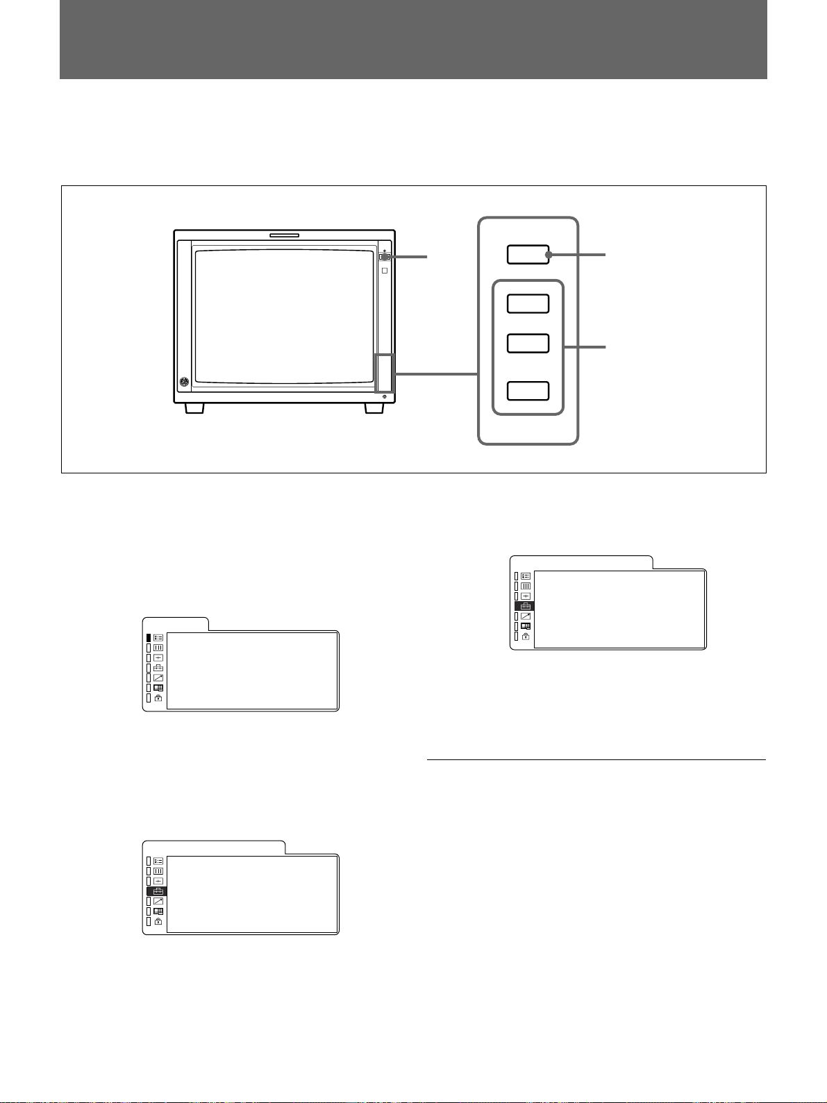
Control Panels
qd
qf
qg
qh
qj
qk
ql
w;
wa
ws
wd
wf
wg
wh
wj
LINE
A
LINE
B
RGB/
COMP
OPTION
A
OPTION
B
EXT
SYNC
UNDER
SCAN
16:9
BLUE
ONLY
MONO
H/V
DELAY
4:3
MARKER
DEGAUSS
RESET
qa
qs
CONTROL
VOLUME
CONTRAST
PHASE
CHROMA
BRIGHT
MENU
UP
DOWN
ENTER
1
2
3
4
5
6
7
8
9
0
1 POWER switch ( )
Press the switch to turn on the power. The operation
buttons on both sides of the unit turn on. Press the
switch again to turn off the power.
2 CONTROL button
Press this button to turn on and enables the operation
button. Press this button again to turn off and disables
the operation buttons.
You can adjust the brightness of the operation buttons by
using the UP or DOWN buttons.
3 VOLUME control button
Press the + button to increase the volume or – button
to decrease the volume.
4 CONTRAST control button
Press the + button to make the contrast higher or the –
button to make it lower.
8 (GB)
5 PHASE control button
Press the + button to make the complexion greenish or
the – button to make it purplish.
6 CHROMA control button
Press the + button to increase the color intensity or the
– button to decrease it.
7 BRIGHT (brightness) control button
Press the + button to increase the brightness or the –
button to decrease it.
Notes
•The PHASE (5) and CHROMA (6) control buttons
have no effect on the pictures of RGB signals.
•The PHASE (5) control button has no effect on the
PAL signals and pictures of component signals.
8 MENU button
Press this button to display or exit the main menu.

9 UP button
Down button
Use these buttons to select an item from a menu or
adjust the values. If the menu is not displayed, you can
use these buttons to adjust the brightness for the control
panels. You can adjust the brightness at 5 levels.
0 ENTER button
Press the button to confirm a selected item on the
menu.
qa Tally lamp
Lights up when the video camera connected to this
monitor is selected, indicating that the picture is being
recorded.
For details on how to light the tally lamp, see page 25 (GB).
qs POWER indicator
Press the POWER switch, the indicator will light
green.
qd LINE A (INPUT A) select button
Press this button to monitor the signal through the
LINE A connector.
qf LINE B (INPUT B) select button
Press this button to monitor the signal through the
LINE B connector.
qg RGB/COMP select button
Press this button to monitor the signal through the
RGB/COMPONENT connectors.
You can set the RGB/COMPONENT in the menu
screen. For details, see page 19 (GB).
ql UNDER SCAN button
Press this button (light on) for underscanning.
The display size is reduced by approximately 5% so
that four corners of the raster are visible.
w; 16:9 button
Press this button to monitor the signals of 16:9 picture.
Note
The aspect ratio is fixed to 16:9 when the signal other
than 4:3 signal format is input.
wa BLUE ONLY button
Press this button to eliminate the red and green signals.
Only blue signal is displayed as an apparent
monochrome picture on the screen. This facilitates
“chroma” and “phase” adjustments and observation of
VCR noise.
ws MONO button
Press this button to display a monochrome picture.
When the buttons is pressed again, the monitor
switches automatically to color mode.
wd H/V DELAY button
Press this button to observe the horizontal and vertical
sync signals at the same time.
The horizontal sync signal is displayed in the left
quarter of the screen; the vertical sync signal is
displayed near the center of the screen.
wf 4:3 MARKER button
When this button is pressed, a 4:3 marker is displayed
and it is possible to check the 4:3 aspect area.
qh OPTION A button
This button is used if an option board has been
installed in the option slot in the monitor’s rear. Press
this button to monitor the image/audio signals from the
option board input 1.
qj OPTION B button
This button is used if an option board has been
installed in the option slot in the monitor’s rear. Press
this button to monitor the image/audio signals from the
option board input 2.
(This button is disabled if BKM-129X or BKM155DV is used.)
qk EXT SYNC (external sync) button
Press this button to operate the monitor on an external
sync signal through the EXT SYNC IN connector.
Note
The 4:3 marker is not displayed when the signals of
the 4:3 aspect ratio are monitored or the monitor is in
H/V delay mode
wg DEGAUSS button
Press this button momentarily. The screen will be
demagnetized. Wait for 10 minutes or more before
using this button again.
wh RESET button
You can reset the menu settings by pressing this button
when a menu is on the display.
wj PROBE connector
Connect to the BKM-14L Auto Set-up Probe when
adjusting auto white balance.
9 (GB)
Location and Function of Parts and Controls
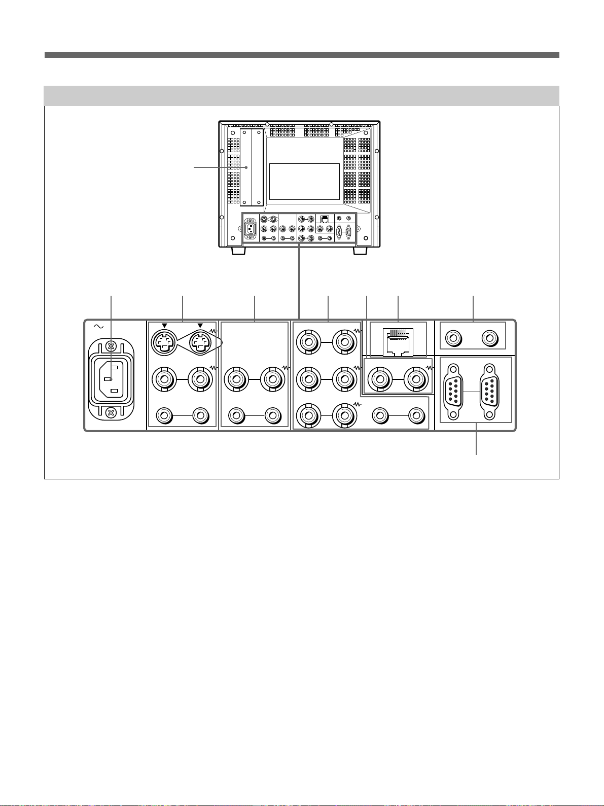
Rear Panel
1
2
AC IN LINE A LINE B
34
IN OUT
VIDEO
IN OUT
AUDIO
IN OUT
VIDEO
IN OUT
AUDIO AUDIO
1 Option slot
You can insert an option board into this option slot. To
use this slot, remove the slot cover by removing the
screws.
You can install only one option board. For details on how to
install a board, refer to the Operating Instructions supplied
with the option board.
2 AC IN socket
Connect the supplied AC power cord to this socket and
to a wall outlet.
3 LINE A connectors
Line input connectors for the Y/C separate input/
output of a VCR, composite video and audio signals
and their loop-through output connectors.
To monitor the input signal through these connectors,
press the LINE A select button on the front panel.
If you connect the Y/C input and video input
simultaneously, the Y/C input is selected first.
567 8
RGB/COMPONENT
G/Y
IN OUT
B/P
B
IN OUT IN OUT
R
R/P
PARALLEL REMOTE
IN OUT
EXT
SYNC
OPTION AUDIO INPUT
12
SERIAL REMOTE
IN OUT
9
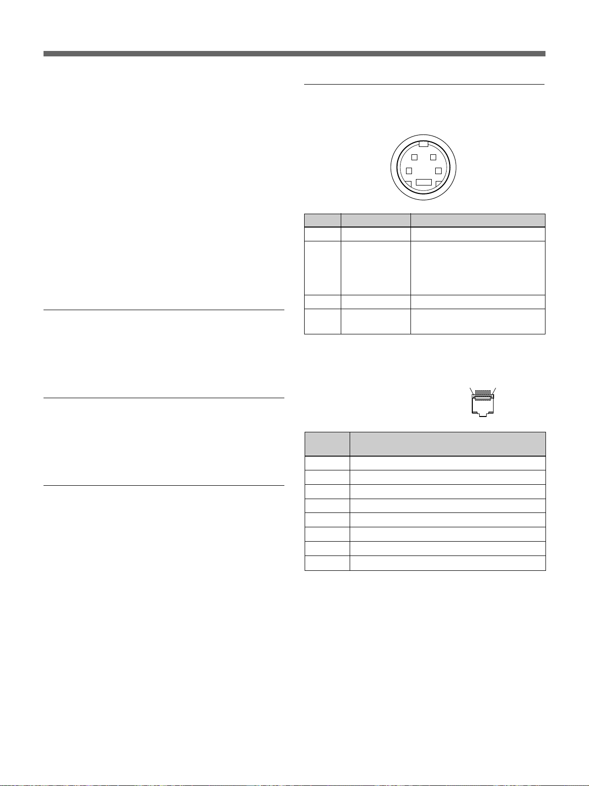
Y/C IN (4-pin mini-DIN)
Connect to the Y/C separate output of a VCR,
video camera or other video equipment.
Y/C OUT (4-pin mini-DIN)
Loop-through output of the Y/C IN connector.
Connect to the Y/C separate input of a VCR or
another monitor.
When the cable is connected to this connector, the
75-ohm termination of the input is automatically
released, and the signal input to the Y/C IN
connector is output from this connector.
VIDEO IN (BNC)
Connect to the video output of video equipment,
such as a VCR or a color video camera.
For a loop-through connection, connect to the video
output of another monitor.
10 (GB)

VIDEO OUT (BNC)
Loop-through output of the VIDEO IN connector.
Connect to the video input of a VCR or another
monitor.
When the cable is connected to this connector, the
75-ohm termination of the input is automatically
released, and the signal input to the VIDEO IN
connector is output from this connector.
AUDIO IN (phono jack)
Connect to the audio output of a VCR or to a
microphone via a suitable microphone amplifier.
For a loop-through connection, connect to the audio
output of another monitor.
AUDIO OUT (phono jack)
Loop-through output of the AUDIO IN connector.
Connect to the audio input of a VCR or another
monitor.
4 LINE B connectors
Line input connectors for the composite video and
audio signals and their loop-through output connectors.
To monitor the input signal through these connectors,
press the LINE B select button on the front panel.
VIDEO IN (BNC)
Connect to the video output of video equipment,
such as a VCR or a color video camera.
For a loop-through connection, connect to the video
output of another monitor.
VIDEO OUT (BNC)
Loop-through output of the VIDEO IN connector.
Connect to the video input of a VCR or another
monitor.
When the cable is connected to this connector, the
75-ohm termination of the input is automatically
released, and the signal input to the VIDEO IN
connector is output from this connector.
AUDIO IN (phono jack)
Connect to the audio output of a VCR or to a
microphone via a suitable microphone amplifier.
For a loop-through connection, connect to the audio
output of another monitor.
AUDIO OUT (phono jack)
Loop-through output of the AUDIO IN connector.
Connect to the audio input of a VCR or another
monitor.
5 RGB/COMPONENT connectors
RGB signal or component (G/Y, B/P
B, R/PR) signal
input/output connectors and their loop-through output
connectors.
To monitor the input signal through these connectors,
press the RGB/COMP select button on the front panel.
G/Y, B/PB, R/PR IN (BNC)
When the EXT SYNC button on the front panel is
not pressed (the indicator lights in green), the
monitor operates on the sync signal from the G/Y
signal.
To monitor the RGB signal
Connect to the analog RGB signal outputs of a
video camera, etc.
To monitor the component signal
Connect to the component signal outputs of a Sony
Betacam video camera, etc.
G/Y, B/PB, R/PR OUT (BNC)
Loop-through outputs of the G/Y, B/PB, R/PR IN
connectors.
When the cables are connected to these connectors,
the 75-ohm termination of the inputs is
automatically released, and the signal inputs to G/
B, R/PR IN connectors are output from these
Y, B/P
connectors.
To output the RGB signal
Connect to the analog RGB signal inputs of a video
printer or another monitor.
To output the component signal
Connect to the component signal inputs of a
Betacam video recorder, etc.
AUDIO IN (phono jack)
Connect to the audio output of video equipment
when the analog RGB or component signal is input.
AUDIO OUT (phono jack)
Loop-through output of the AUDIO IN connector.
11 (GB)

Location and Function of Parts and Controls
6 EXT SYNC (external sync) connectors
Press the EXT SYNC button on the front panel (the
indicator lights in amber) to use the sync signal
through this connector.
IN (BNC)
When this monitor operates on an external sync
signal, connect the reference signal from a sync
generator to this connector.
OUT (BNC)
Loop-through output of the IN connector. Connect
to the external sync input of video equipment to be
synchronized with this monitor.
When the cable is connected to this connector, the
75-ohm termination of the input is automatically
released, and the signal input to the IN connector is
output from this connector.
7 PARALLEL REMOTE terminal (modular
connector)
Form a parallel switch and controls the monitor
externally.
For details on the pin assignment and factory setting
function assigned to each pin, see page 25 (GB).
9 SERIAL REMOTE connector (D-sub 9 pins)
SERIAL REMOTE IN
Connect this connector to the Serial Remote
Control connector on the BVM series unit.
You can control the functions except the menu in
the control panel of the unit from the BVM.
However you cannot control these functions from
this unit in this mode.
SERIAL REMOTE OUT
Loop-through output of the SERIAL REMOTE IN
connector.
8 OPTION AUDIO INPUT 1, 2 input connectors
If an option board has been installed in the option slot,
input the audio into these connectors. Connect to the
audio output of a VCR or to a microphone amplifier.
You can connect up to 2 systems. To monitor the audio
signals input from the OPTION AUDIO INPUT 1/2,
press either the OPTION A or OPTION B buttons.
Note
If you use an optional board (e.g. BKM-150CP) with
the audio capability, the audio input into this connector
is ignored.
12 (GB)
Selecting the Menu Language
You can select one of six languages (English, German, French, Italian, Spanish, Japanese) for displaying the menu
and other on-screen displays.
The factory setting is ENGLISH (English).
1 Press the POWER switch to turn on the monitor.
2 Press the MENU button.
The menu appears.
The menu presently selected is shown as a yellow
button.
STATUS
FORMAT COMPONEN T
1 480/60I
COLOR TEMP D65
COMP LEVEL SMPTE
NTSC SETUP 0
RGB / COMP SEL COMP
OPT I ON
1
MENU
UP
DOWN
ENTER
2
3,4,5
4 Press the UP or DOWN button to select
“LANGUAGE,” then press the ENTER button.
The selected item is displayed in yellow.
USER CONF IG 1 / 2
·RGB/COMP SEL COMP
·COMP LEVEL SMPTE
·FORMAT DISP AUTO
x LANGUAGE ENGL I S H
·DEGAUSS DE LAY 0
5 Press the UP or DOWN button to select a
language, then press the ENTER button.
The menu changes to the selected language.
3 Press the UP or DOWN button to select the USER
CONFIG 1/2 (User Configuration 1/2) menu, then
press the ENTER button.
The setting items (icons) in the selected menu are
displayed in yellow.
USER CONF IG 1 / 2
x RGB / COMP S E L COMP
·COMP LEVEL SMPTE
·FORMAT DISP AUTO
·LANGUAGE ENGL I SH
·DEGAUSS DELAY 0
To clear the menu
Press the MENU button.
The menu disappears automatically if a button is not
pressed for one minute.
13 (GB)
Using the Menu
The monitor is equipped with an on-screen menu for
making various adjustments and settings such as
picture control, input setting, set setting change, etc.
You can also change the menu language displayed in
the on-screen menu.
To change the menu language, see “Selecting the Menu
Language” on page 13 (GB).
1 Press the MENU button.
The menu appears.
The menu presently selected is shown as a yellow
button.
STATUS
FORMAT COMPONEN T
1 480/60I
COLOR TEMP D65
COMP LEVEL SMPTE
NTSC SETUP 0
RGB / COMP SEL COMP
OPT I ON
2 Use the UP or DOWN button to select a menu,
then press the ENTER button.
The menu icon presently selected is shown in
yellow and setting items are displayed.
Menu Setting items
When changing the setting:
Press the UP or DOWN button to change the
setting.
Press the ENTER button to confirm the setting.
Notes
•An item displayed in blue cannot be accessed. You
can access the item if it is displayed in white.
•If the key protect has been turned on, all items are
displayed in blue. To change any of the items, turn
the key protect to OFF first.
For details on the key protect, see page 22 (GB).
To clear the menu
Press the MENU button.
The menu disappears automatically if a button is not
pressed for one minute.
About the memory of the settings
The settings are automatically stored in the monitor
memory.
USER CONF IG 1 / 2
x RGB / COMP S E L COMP
·COMP LEVEL SMPTE
·FORMAT DISP AUTO
·LANGUAGE ENGL I SH
·DEGAUSS DELAY 0
3 Select an item.
Use the UP or DOWN button to select the item,
then press the ENTER button.
The item to be changed is displayed in yellow.
Note
If the menu consists of multiple pages, press UP/
DOWN to go to the desired menu page.
4 Make the setting or adjustment on an item.
When changing the adjustment level:
To increase the number, press the UP button.
To decrease the number, press the DOWN button.
Press the ENTER button to confirm the number,
then restore the original screen.
To reset items that have been adjusted
Pressing the RESET button while you are adjusting the
VOLUME, CONTRAST, PHASE, CHROMA or
BRIGHT buttons on the control panels resets the level
to the standard. Pressing the RESET button while you
are adjusting any of the menu items resets the menu
item to the previous setting.
14 (GB)
Display List
STATUS menu
STATUS
FORMAT COMPONEN T
1 480/60I
COLOR TEMP D65
COMP LEVEL SMPTE
NTSC SETUP 0
RGB / COMP SEL COMP
OPT I ON
COLOR TEMP/BAL menu
When D65 or D93 is selected. (In
the illustration, D65 is selected.)
COLOR TEMP/BAL
·COLOR TEMP D 6 5
·MANUAL /AUTO MANUAL
·ADJUST GA I N...
·ADJUST BIAS...
·COPY FROM D65
USER CONTROL 1/2, 2/2 menu
(NTSC)
USER CONTROL 1/2
AUTO CHROMA / PHASE
·AUTO ADJ VALUE OFF
·START...
USER MEMORY
·LOAD STANDARD
·SAVE MEMORY1
When USER is selected and MANUAL is
selected.
COLOR TEMP/BAL
x COLOR TEMP USE R
·MANUAL/AUTO MANUAL
·ADJUST GA I N...
·ADJUST BIAS...
·COPY FROM D65
USER CONTROL 2/2
SUB CONTROL
x CONT RAS T 5 0
·BRIGHT 0
·CHROMA 50
·PHASE 0
·APERTURE OFF
When USER is selected and AUTO is
selected.
COLOR TEMP / BAL
· COLOR TEMP U SER
xMA NUA L /AUTO AUTO
· START...
TARGET VALUE
·X 0.313
·Y 0.329
·REF VALUE D65
15 (GB)
Display List
USER CONFIG 1/2, 2/2 menu
(USER CONFIG 1/2 menu) (USER CONFIG 2/2 menu)
USER CONF IG 1 / 2
·RGB/COMP SEL COMP
·COMP LEVEL SMPTE
·FORMAT DISP AUTO
·LANGUAGE ENGL I SH
·DEGAUSS DELAY 0
REMOTE 1/2 PARALLEL menu, 2/2 SERIAL menu
(REMOTE 1/2 PARALLEL menu) (REMOTE 2/2 SERIAL menu)
REMOTE 1 / 2 PARA LL EL
·1PIN LINE A
·2PIN LINE B
·3PIN TALLY R
·4PIN TALLY G
·6PIN EXT SYNC
·7PIN UNDERSCAN
·8PIN 16:9
USER CONF IG 2 / 2
xM ARKER PHASE 0
·MARKER W IDTH 0
REMOTE 2 / 2 SER I AL
x SINGLE ADDRESS 0
·GROUP ADD RES S 0
·CH(1–4) CONFIG CH1
·INPUT LINE A
·ASPECT 4:3
·SCAN SIZE NORMAL
OPTION CONFIG menu
For details on the OPTION CONFIG menu screens, see page 21 (GB).
KEY PROTECT menu
KEY PROTECT
·KEY PROTECT OF F
16 (GB)
STATUS Menu
The STATUS menu is used to display the current
status of the monitor. The following items are
displayed:
•Signal format
•Color temperature
•Component level
•NTSC setup
•RGB/COMP select
•Option
COLOR TEMP/BAL
Menu
The COLOR TEMP/BAL menu is used for adjusting
the picture white balance.
You need to use the measurement instrument to adjust
the white balance.
COLOR TEMP
Select the color temperature from among D65, D93
and USER setting.
ADJUST GAIN…
If you set the [COLOR TEMP] to USER setting and
[MANUAL/AUTO] to MANUAL, you can adjust the
color balance (GAIN).
Select [ADJUST GAIN…]. The [ADJUST GAIN…]
screen appears. Adjust the gain by pressing the UP or
DOWN button.
ADJUST BIAS…
If you set the [COLOR TEMP] to USER setting and
[MANUAL/AUTO] to MANUAL, you can adjust the
color balance (BIAS).
Select [ADJUST BIAS…]. The [ADJUST BIAS…]
screen appears. Adjust the bias by pressing the UP or
DOWN button.
COPY FROM
If you set the [COLOR TEMP] to USER setting and
[MANUAL/AUTO] to MANUAL, you can set the
color temperature to D65 or D93 using the UP or
DOWN button.
If you select D65 or D93 with the UP or DOWN
button, the white balance data for the selected color
temperature will be copied in the user setting.
MANUAL/AUTO
If you set the [COLOR TEMP] to USER setting, the
item displayed is changed from blue to white, which
means you can adjust the color temperature.
If you select MANUAL, the following items
“ADJUST GAIN...”, “ADJUST BIAS...” and “COPY
FROM” appear in the menu.
If you select AUTO, move the cursor to START using
UP or DOWN button and press ENTER. The
adjustment starts automatically.
Note
The BKM-14L Auto Set-up Probe is needed to execute
auto white balance adjustment.
17 (GB)

USER CONTROL 1/2, 2/2 Menu
The USER CONTROL 1/2, 2/2 menu is used for
adjusting the picture.
Items that cannot be adjusted depending on the input
signal are displayed in blue.
AUTO CHROMA/PHASE
Adjusts color intensity (CHROMA) and tones
(PHASE).
AUTO ADJ VALUE
Selects ON or OFF of the Auto adjustment. When set
to OFF, this parameter is reset to the factory setting.
When set to ON the automatically adjusted value is
enabled.
START…
Display the color bar signals (Full/SMPTE/EIA/HD)
on the screen and press ENTER. The AUTO
ADJUSTMENT screen starts. Exit from the AUTO
ADJUSTMENT screen using the MENU button after
finishing adjustment. When the adjustment is done
correctly, the AUTO ADJ VALUE is automatically
enabled.
Note
If you have selected the full color bars, enter eight
color bars.
SUB CONTROL
You can finely adjust the adjustment range of buttons
on the right-side of the front panel; CONTRAST,
PHASE, CHROMA and BRIGHT buttons.
CONTRAST
Adjusts the picture contrast. You can adjust the
contrast from 0 to 100.
BRIGHT
Adjusts the picture brightness. You can adjust the
brightness from –50 to +50.
CHROMA
Adjusts color intensity. The higher the setting, the
greater the intensity.
The lower the setting, the lower the intensity. You can
adjust the color intensity from 0 to 100.
PHASE
Adjusts color tones. The higher the setting, the
complexion becomes greenish.
The lower the setting, the picture becomes purplish.
You can adjust the color tones from –50 to +50.
APERTURE
Adjusts the picture sharpness. The higher the setting,
the sharper the picture. You can adjust the color
sharpness from OFF to 100.
USER MEMORY
SAVE
Saves the current VOLUME, CONTRAST, PHASE,
CHROMA or BRIGHT settings on the control panels.
You can select MEMORY1 or MEMORY2 area to
save the data.
LOAD
Loads the VOLUME, CONTRAST, PHASE,
CHROMA or BRIGHT setting of the control panels
from the setting saved in a memory described above. If
you select Standard, the settings are reset to the
standards.
18 (GB)

USER CONFIG 1/2, 2/2 Menu
You can select a language, RGB and component.
The settings in parentheses [ ] are factory settings.
RGB/COMP SEL
To monitor the signal fed through the RGB/
COMPONENT connectors, set the RGB or COMP
(component) signal in this menu. Press the UP or
DOWN button to select the RGB or COMP signal.
[COMP]
COMP LEVEL
Select the component level from among three modes.
N10/SMPTE for 100/0/100/0 signal
BETA 7.5 for 100/7.5/75/7.5 signal
BETA 0 for 100/0/75/0 signal
[SMPTE]
NTSC SETUP
DEGAUSS DELAY
Set the delay time of auto degaussing to start working
after the power is turned on. The delay time can be set
within 0 to 99 seconds.
[0]
LANDING
This menu is provided only for PVM-20L4.
If the color is not uniform even after you press the
DEGAUSS button, you can adjust the landing so as to
obtain color uniformity on this screen. [50]
The following two methods are available to adjust the
landing.
When the signals of the horizontal lines are input
and displayed:
Press the UP or DOWN button until the lines are
displayed on the screen as horizontally as possible.
The horizontal lines can be adjusted within 0 to 100.
Select the NTSC setup level from two modes.
The 7.5 setup level is mainly used in North America.
The 0 setup level is mainly used in Japan.
FORMAT DISP
Select the display mode of the signal format from
among ON, OFF and AUTO.
[AUTO]
LANGUAGE
You can select the menu or message language from
among six languages (Japanese, English, German,
French, Italian, Spanish).
Select a language by pressing the UP or DOWN
button, then press the ENTER button. The selected
language is displayed.
[ENGLISH]
[0]
When the signals of the white color are input and
displayed:
Press the UP or DOWN button until the white color on
the screen become as uniform as possible. The level of
the white color signals can be adjusted within 0 to 100.
MARKER PHASE
You can adjust the 4:3 marker position within –10 to
+10.
[0]
MARKER WIDTH
You can adjust the 4:3 marker width within –10 to
+10.
[0]
19 (GB)
REMOTE 1/2
PARALLEL Menu
Select the PARALLEL REMOTE connector pins for
which you want to change the function.
You can assign various functions to 1 to 4 pins and 6
to 8 pins. The following lists the functions you can
assign to the pins.
•– – (“– –”: No function
is assigned.)
•LINE A
•LINE B
•RGB/COMP
•OPTION A
•OPTION B
•TALLY RED
•TALLY GREEN
Note
If you use the PARALLEL REMOTE function, you need
to connect cables. For more details, see page 25 (GB).
•UNDERSCAN
•16:9
•EXT SYNC
•H/V DELAY
•BLUE ONLY
•MONO
•4:3 MARKER
•DEGAUSS
REMOTE 2/2 SERIAL
GROUP ADDRESS
Set the monitor group address number. You can set
within 0 to 99.
CH(1-4) CONFIG
Set the channel numbers (1 to 4) that have been
assigned to the direct keys in the BVM series unit.
Select from among CH1, CH2, CH3 and CH4.
You can set the channel for INPUT, ASPECT and
SCAN SIZE.
INPUT
Sets the input system to the selected channels.
Select from among LINE A, LINE B, RGB/COMP,
OPTION A and OPTION B.
ASPECT
Sets the aspect ratio of the picture.
Select 16:9 or 4:3.
Menu
When you control this unit by using the serial remote
mode from the BVM series unit, set the monitor single
address and group address, or the channel number you
want to assign in this menu.
SINGLE ADDRESS
The following lists the functions that can be performed
by a serial remote command from a BVM series unit:
•CONTRAST
adjustment
•BRIGHT adjustment
•CHROMA adjustment
•PHASE adjustment
•Numeric keypad 1
button
•Numeric keypad 2
button
•Numeric keypad 3
button
•Numeric keypad 4
button
•Underscan button
•Horizontal delay
button*
•Vertical delay button*
•Monochrome button
•Aperture button
•16:9 button
•SYNC button
•Blue only button
•Safe area button
The system of this unit
*
functions in the H/V
DELAY mode.
SCAN SIZE
Sets the size of a picture which is displayed by
scanning the input signal.
Select UNDER or NORMAL.
BVM-Series PVM-14L4/
20L4/14L3
Serial Remote Control Configuration Example
Note
If you perform a single control multiple times
continuously in the serial mode, the remote state may
be disabled. In this case, execute the same control
command several times until the remote state is
recovered.
PVM-14L4/
20L4/14L3
20 (GB)
OPTION CONFIG Menu
Sets the option boards installed in the rear. Depending
on the installed board, the displayed screen may differ.
If no board is installed, the item settings are not
displayed. After assigning the input signal, adjust the
monitor’s AUTO CHROMA/PHASE.
When installing the optional board BKM150CP:
O P T I O N C O N F I G
B K M – 1 5 0 C P
S E R I A L x x x x x x x x
F A N O K
· F O R M A T S D T I – C P
· A U D I O C H C H 1 + C H 2
· T I M E C O D E O F F
FORMAT
Sets the signal type.
Select SDTI-CP or SDI.
AUDIO
Selects an audio channel.
D1-SDI:
Select from among CH1+CH2 through
CH15+CH16, or CH1 through CH16.
SDTI-CP:
Select from among CH1+CH2 through CH7+CH8,
or CH1 through CH8.
The audio signal input to the OPTION AUDIO INPUT
1/2 jack is ignored.
PR188: SMPTE RP188 Time Code
VITC: SMPTE 12M VITC, SMPTE 266M D-VITC
When installing the optional board BKM155DV:
O P T I O N C O N F I G
B K M – 1 5 5 D V
S E R I A L x x x x x x x x
F O R M A T D V
· A U D I O C H C H 1 + C H 2
F A N O K
AUDIO
Selects an audio channel.
Select from among CH1+CH2, CH3+CH4,
CH1/3, CH2/4, CH1/3+CH2/4, or CH1 through
CH4.
The audio signal input to the OPTION AUDIO INPUT
1/2 jack is ignored.
When installing the optional board BKM120D:
OPT I ON CONF I G
BKM–12 0D
SERI AL xxxxxxxx
TIME CODE
Selects the time code display.
D1-SDI:
Select VITC, RP188 or OFF.
SDTI-CP:
Select VITC, CP-TC1, CP-TC2, ES-TC1, ES-TC2
or OFF.
The following lists the abbreviations in the menu and
their full names:
CP-TC1: SMPTE 331M System Item USER DATE/
TIME STAMP
CP-TC2: SMPTE331M System Item CREATION
DATE/TIME STAMP
ES-TC1: SMPTE 328M MPEG ES Editing
Information TIME CODE1
ES-TC2: SMPTE 328M MPEG ES Editing
Information TIME CODE2
When installing the optional board BKM129X:
OPT I ON CONF I G
BKM–12 9X
SERI AL xxxxxxxx
If the cooling fan in the BKM-150CP or BKM-155DV
is stopped, the screen shows the following message in
red “BKM-xxxxx FAN ERROR”. In this case, you
cannot select Option A or Option B.
21 (GB)

KEY PROTECT Menu
Troubleshooting
You can lock the settings so that they cannot be
changed by an unauthorized user.
Select OFF or ON.
If you set ON, all items are displayed in blue,
indicating the items are locked.
This section may help you isolate the cause of a
problem and as a result, eliminate the need to contact
technical support.
•The display is colored in green or purple. t
Select the correct input by pressing one of the buttons
related to input.
•The unit cannot be operated. t The key protection
function works. Set the KEY PROTECT setting to
OFF in the KEY PROTECT menu.
•The BKM-150CP or BKM-155DV has been
installed. The error message “BKM-xxxxx FAN
ERROR” is displayed and you cannot select
Option A or Option B. t Repair the BKM-xxxxx.
22 (GB)
Specifications
General
System
System
575/50I (PAL) 625 575 25 2:1 Interlace 16:9/4:3 ITU 601
480/60I (NTSC) 525 483 30 2:1 Interlace 16:9/4:3 ITU 601
Total lines Active lines
per frame per frame
PVM-14L4
CRT: HR Trinitron, EBU standard
luminescent material
Power: AC100 to 240V, 50/60Hz
Frame
rate
(Hz)
Scanning Aspect
format ratio
Dimensions (max.):
Approx. 452 × 414 × 500mm
(w/h/d)
Mass: Approx. 31kg
Standard
Power consumption:
Maximum 100W, 1.0 to 0.5A
(when the optional BKM-150CP
has been installed)
Standard: 88W, 0.9 to 0.4A
(without optional board)
Peak inruch current
(1) Power ON, current probe
method: 53 A (240 V)
(2) Hot switching inrush current,
measured in accordance with
European standard EN55103-1:
35 A (230 V)
Dimensions (max.):
Approx. 346 × 280 × 424mm
(w/h/d)
Mass: Approx. 17kg
PVM-14L3
CRT: Trinitron, P-22 standard
luminescent material
Power: AC100 to 240V, 50/60Hz
Power consumption:
Maximum 100W, 1.0 to 0.5A
(when the optional BKM-150CP
has been installed)
Standard 88W, 0.9 to 0.4A (without
optional board)
Peak inruch current
(1) Power ON, current probe
method: 53 A (240 V)
(2) Hot switching inrush current,
measured in accordance with
European standard EN55103-1:
35 A (230 V)
PVM-20L4
CRT: HR Trinitron, EBU standard
luminescent material
Power: AC100 to 240V, 50/60Hz
Dimensions (max.):
Approx. 346 × 280 × 424mm
(w/h/d)
Mass: Approx. 16.5kg
Power consumption:
Maximum 123W, 1.3 to 0.6A
(when the optional BKM-150CP
has been installed)
Input/output connectors
Standard: 110W, 1.1 to 0.5A
(without optional board)
Peak inruch current
(1) Power ON, current probe
method: 53 A (240 V)
(2) Hot switching inrush current,
measured in accordance with
European standard EN55103-1:
Input
LINE A input connector
Y/C input 4-pin mini-DIN (1)
See the pin assignment
VIDEO input
BNC type (1) 1Vp-p ± 6dB
negative synchronization
35 A (230 V)
23 (GB)

Specifications
AUDIO input
Pin jack (1) –5dBu 47 kΩ or higher
LINE B input connector
VIDEO input
BNC type (1) 1Vp-p ± 6dB
negative synchronization
AUDIO input
Pin jack (1) –5dBu 47 kΩ or higher
RGB/Component input connector
BNC type (3)
RGB input 0.7Vp-p ± 6dB (Sync On Green,
0.3Vp-p negative sync.)
Component input
0.7Vp-p ± 6dB (75% chrominance
standard color bar signal)
AUDIO input
Pin jack (1) –5dBu 47 kΩ or higher
Externally synchronized input
BNC type (1) 0.3 to 8Vp-p ±
bipolarity ternary or negative
polarity binary
LINE B output connector
VIDEO output
BNC type (1) Loop-through, with
75 Ω automatic terminal function
AUDIO output
Pin jack (1) Loop-through
RGB/Component output connector
BNC type (3) RGB/Component output
Loop-through, with 75 Ω automatic
terminal function
AUDIO output
Pin jack (1) Loop-through
Externally synchronized output
BNC type (1) Loop-through, with 75 Ω
automatic terminal function
Remote output
Serial remote
D-Sub 9-pin (1) Loop-through
Video signal
Optional AUDIO input
Pin jack (2) –5dBu 47 kΩ or higher
Remote input
Serial remote
D-Sub 9-pin (1)
Parallel remote
Modular connector 8-pin (1)
Output
LINE A output connector
Y/C output 4-pin mini-DIN (1) Loop-through,
with 75 Ω automatic terminal
function
VIDEO output
BNC type (1) Loop-through, with
75 Ω automatic terminal function
AUDIO output
Pin jack (1) Loop-through
Frequency response
PVM-14L4/20L4: 50 Hz to 10
MHz (0 dB/–3 dB)
Aperture compensation
1)
OFF: 0 dB
ON: 2 dB to 6 dB
Picture performance
Normal scan 7% overscan of CRT effective
screen area
Underscan 5% underscan of CRT effective
screen area
Linearity PVM-14L4/14L3
H: 4% or less
V: 4% or less
PVM-20L4
H: 5% or less
V: 5% or less
Color temperature
D65, D93/USER (Adjustable color
temperature: 5000K to 10000K)
.........................................................................................................................................................................................................
1) The aperture cannot be compensated for RGB input signals.
24 (GB)
Convergence error
PVM-14L4/14L3
Center: 0.4mm or less
Peripheral: 0.5mm or less
PVM-20L4
Center: 0.5mm or less
Peripheral: 0.7mm or less
Raster size stability
H: 1.0%
V: 1.0%
Resolution (at screen center)
PVM-14L4/20L4:
600 TV lines (16:9)
800 TV lines (4:3)
PVM-14L3:
600 TV lines (4:3)
Operating conditions
Temperature 0 °C to 35 °C
Humidity 30% to 85% (no condensation)
Pressure 700 hPa to 1060 hPa
Pin assignment
Y/C IN connector (4-pin mini-DIN)
21
34
*
Pin No.
1
2
3
4
PARALLEL REMOTE terminal
Modular connector
(8-pin)
Signal
Y-input
CHROMA-input
Subcarrier-input
GND for Y-input
GND for
CHROMA-input
1 Vp-p, sync negative, 75 ohms
286 mVp-p (NTSC)/
300 mVp-p (PAL) ,
burst
Delay time between Y and C:
within 0 ±100 nsec., 75 ohms
GND
GND
Description
81
Storage and transport conditions
Temperature –10 °C to 40 °C
Humidity 0% to 90%
Pressure 700 hPa to 1060 hPa
Accessories supplied
AC power cord (1)
AC plug holder (1)
Operating Instructions (1)
Design and specifications are subject to change
without notice.
Pin
number
1 Set input signal LINE A
2 Set input signal LINE B
3 Set red tally lamp on or off
4 Set green tally lamp on or off
5 GND
6 Select EXT sync
7 Select underscan
8 Select aspect ratio 16:9
Functions
You can allocate functions to 1 to 4 pins or 1 to 8 pins
in the Remote menu.
Wiring required to use the Remote Control
Connect the function you want to use in remote to the
Ground (Pin 5).
25 (GB)
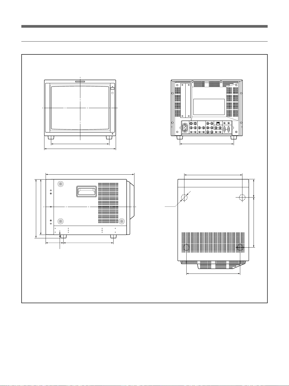
Specifications
Dimensions
PVM-14L4/14L3
Front
Side
279.5
265
280
345.6
424
Rear
Top
260
280
83.9
φ
16
83.9
240
240
0.5
260
Unit: mm
26 (GB)
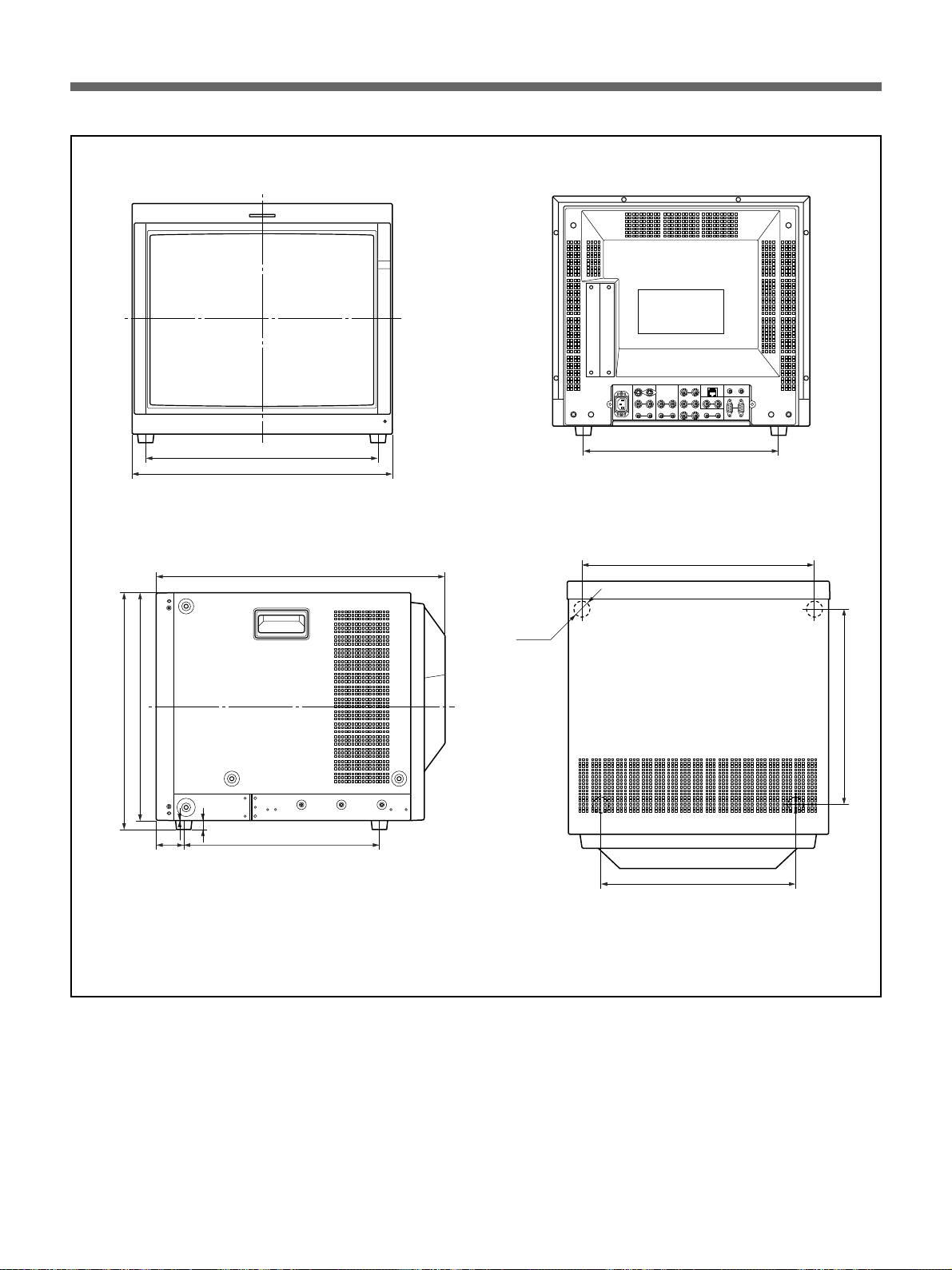
PVM-20L4
Front
Side
406
452.2
500
Rear
Top
φ
340
406
16
399
413.5
46.2
340
0.5
340
340
Unit: mm
27 (GB)

Français
AVERTISSEMENT
Afin d’éviter tout risque d’incendie ou
d’électrocution, ne pas exposer cet
appareil à la pluie ou à l’humidité.
Des courants de hautes tensions
dangereuses sont présents à l’intérieur de
cet appareil. Ne pas ouvrir le coffret.
S’adresser à un personnel qualifié
uniquement.
Dans le cas d’une défaillance ou de nécessité
d’entretien, consulter un revendeur Sony autorisé.
Pour les clients européens
Ce produit portant la marque CE est conforme à la fois
à la Directive sur la compatibilité électromagnétique
(EMC) (89/336/CEE) et à la Directive sur les basses
tensions (73/23/CEE) émises par la Commission de la
Communauté européenne.
La conformité à ces directives implique la conformité
aux normes européennes suivantes:
• EN60950: Sécurité des produits
• EN55103-1: Interférences électromagnétiques
(émission)
• EN55103-2: Sensibilité électromagnétique
(immunité)
Ce produit est prévu pour être utilisé dans les
environnements électromagnétiques suivants:
E1 (résidentiel), E2 (commercial et industrie légère),
E3 (urbain extérieur) et E4 (environnement EMC
contrôlé ex. studio de télévision).
Ces produits sont conçus pour fonctionner dans les
environnements E1 à E4. Lors de contraintes EMC,
les performances (évaluées en fonction de ITU/R 5623 et ITU/R 500-4) risquent de chuter comme le montre
le tableau 1. Sans contrainte EMC, toutes les
performances reviennent à leur niveau maximum.
ATTENTION – Lorsque le produit est installé
sur un bâti :
a) Température ambiante de service élevée
Si l’appareil est installé sur un bâti fermé ou
comportant plusieurs appareils, la température
ambiante de service du bâti peut être supérieure à
la température ambiante de la pièce. Il convient par
conséquent d’installer l’appareil dans un
environnement compatible avec la température
ambiante nominale maximale indiquée par le
fabriquant (Tmra : 0 °C à 35 °C).
b) Débit d’air réduit
L’installation de l’appareil dans un bâti ne doit pas
entraver la circulation d’air nécessaire au
fonctionnement fiable de l’appareil.
c) Charge mécanique
Le montage de l’appareil sur le bâti ne doit pas
créer de situation dangereuse résultant d’une
charge mécanique irrégulière.
d) Surcharge du circuit
Il convient de porter attention au raccordement de
l’appareil sur le circuit d’alimentation et à l’effet
d’une surcharge des circuits sur la protection contre
les surintensités et le câblage d’alimentation.
Il convient de prendre en compte les
caractéristiques indiquées sur la plaque
signalétique de l’appareil pour régler ce problème.
e) Mise à la terre fiable
Une mise à la terre fiable doit être assurée pour un
appareil installé dans un bâti. Il convient de porter
particulièrement attention aux raccordements
d’alimentation qui ne sont pas des raccordements
directs au circuit de dérivation (par exemple,
l’utilisation de blocs multiprises).
f) Maintien d’un espace de dégagement minimal
Laissez un espace de 44 mm au-dessus et en
dessous d’un appareil installé dans un bâti.
Tableau 1
PVM-14L4/14L3
(Moniteurs 14
pouces)
PVM-20L4
(Moniteur 20
pouces)
2 (FR)
Fréquence
155 – 200 MHz 4,5
259 – 376 MHz
306 – 353 MHz 4,0
259 – 289 MHz/
378 – 418 MHz/
489 – 520 MHz/
535 – 598 MHz
Niveau
4,0 – 4,5
4,5
Précautions
Sécurité
• Faites uniquement fonctionner l’appareil sur l’une
des sources d’alimentation désignées dans les
“Spécifications”.
• La plaquette signalétique indiquant la tension de
service, la consommation électrique, etc., se trouve à
l’arrière de l’appareil.
• Si un liquide ou un objet pénètre à l’intérieur du
châssis, débranchez le moniteur et faites-le contrôler
par un personnel qualifié avant de le remettre en
service.
•Ne laissez pas tomber ou ne placez pas d’objets
lourds sur le cordon d’alimentation. Si ce dernier est
endommagé, mettez immédiatement l’appareil hors
tension. Il est dangereux de faire fonctionner cet
appareil avec un cordon endommagé.
•Débranchez l’appareil de la prise murale si vous ne
prévoyez pas de l’utiliser pendant quelques jours ou
plus.
•Débranchez le cordon de la prise secteur en le tirant
par la fiche, ne tirez jamais sur le cordon proprement
dit.
• La prise d’alimentation doit se trouver à proximité
du moniteur et être aisément accessible.
Installation
Nettoyage de la surface du tube
cathodique (PVM-14L4/20L4 seulement)
• La surface du tube cathodique a subi un traitement
de film PET en option.
Pour éviter d’endommager la surface du tube,
nettoyez-la en employant la méthode suivante :
• Passez un chiffon doux sur le tube.
Si le tube est souillé par des traces de gras ou des
empreintes digitales, nettoyez-le à l’aide d’un
chiffon imprégné d’une solution détergente douce.
•N’employez jamais de nettoyants abrasifs, de savon
alcalin, de produits solvants puissants comme
l’alcool ou la benzine, car ils risquent d’endommager
la surface du tube.
•Ne frottez pas la surface du tube avec un objet solide
et ne le heurtez pas.
Entretien
Pour que le moniteur garde l’aspect du neuf, nettoyezle régulièrement à l’aide d’une solution détergente
neutre. N’utilisez jamais de solvants puissants tels que
du diluant ou de la benzine ou des nettoyants abrasifs
qui risquent d’altérer le fini du châssis. Par mesure de
précaution, débranchez le moniteur avant de le
nettoyer.
FR
Français
•Veillez à assurer une circulation d’air suffisante pour
éviter toute surchauffe à l’intérieur de l’appareil.
Ne placez pas l’appareil sur des surfaces (tapis,
couvertures, etc.) ou à proximité de textiles (rideaux,
tentures) susceptibles d’obstruer les orifices de
ventilation.
•N’installez pas l’appareil à proximité de sources de
chaleur comme un radiateur ou une bouche d’air
chaud ou dans un endroit exposé au rayonnement
solaire direct, ne l’exposez pas à des poussières
excessives, à des vibrations ou à des chocs
mécaniques.
Remballage
Conservez le carton et les matériaux de
conditionnement d’origine. Ils sont parfaits pour
transporter l’appareil. Lorsque vous transportez le
moniteur, remballez-le comme illustré sur le carton.
Si vous avez des questions concernant votre moniteur,
consultez votre revendeur agréé Sony.
3 (FR)

Table des matières
Précautions ................................................................ 3 (FR)
Caractéristiques ........................................................ 5 (FR)
Raccordements.......................................................... 7 (FR)
Raccordement du cordon d’alimentation secteur........... 7 (FR)
Raccordement d’un câble à un connecteur BNC ...........7 (FR)
Emplacement et fonctions des composants et des
commandes................................................................ 8 (FR)
Panneaux de commande................................................. 8 (FR)
Panneau arrière............................................................. 10 (FR)
Sélection de la langue des menus ......................... 13 (FR)
Utilisation du menu .................................................14 (FR)
Liste des menus ...................................................... 15 (FR)
Menu STATUT .......................................................... 17 (FR)
Menu TEMP/BAL COULEUR ................................... 17 (FR)
Menu CONTROLE UTIL 1/2, 2/2 .............................. 18 (FR)
Menu CONFIG UTILISAT 1/2, 2/2 ............................ 19 (FR)
Menu TELECMDE 1/2 PARALL...............................20 (FR)
Menu TELECOMMADE 2/2 SERIE ..........................20 (FR)
Menu CONFIG OPTION ........................................... 21 (FR)
Menu VERROUILLAGE............................................ 22 (FR)
Dépannage ...............................................................22 (FR)
Spécifications ..........................................................23 (FR)
Sauf mention contraire, les explications fournies dans le présent
mode d’emploi s’appliquent aux modèles suivants.
Les explications qui diffèrent pour certains modèles sont
clairement spécifiées dans le présent mode d’emploi.
•PVM-14L4 (moniteur 14 pouces)
•PVM-20L4 (moniteur 20 pouces)
•PVM-14L3 (moniteur 14 pouces)
Les illustrations du moniteur vidéo sont celles du PVM-14L4.
4 (FR)
 Loading...