

Sony TRINITRON PVM-1942Q, TRINITRON PVM-1944Q Operating Instructions Manual
SONYe
TRINITRON@ Color Video Monitor
PVM-1944Q
PVM-1942Q
Operating Instructions Page2
Before operating the unit, please read this manual thoroughly
and retain it for future reference.
Mode d'emploi Page 16
Avant la mlse en service de cet apparel!, priere de lire attentivement
ce mode d'emplol que l'on conservera pour toute reference ulterieure.
Owner's Record
The model and serial numbers are located on the rear.
Record the model and serial numbers in the spaces provided below. Refer
to these numbers whenever you call upon your Sony dealer regarding this
product.
Model No. ______ Serial No. _____ _
0 1989 by Sony Corporation
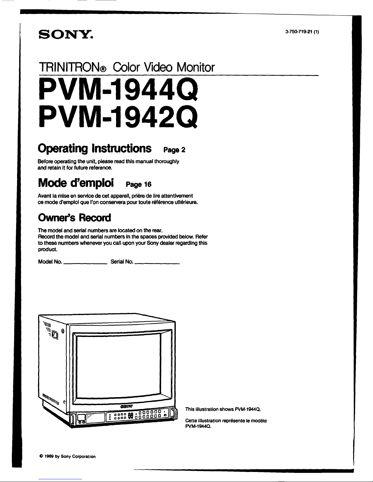
000000 •
:
0000880•000□□0.,
: 0000 ii
This Illustration shows PVM• 1944Q.
Cette Illustration represente le modele
PVM·19440.
3-750-719·21 (1)
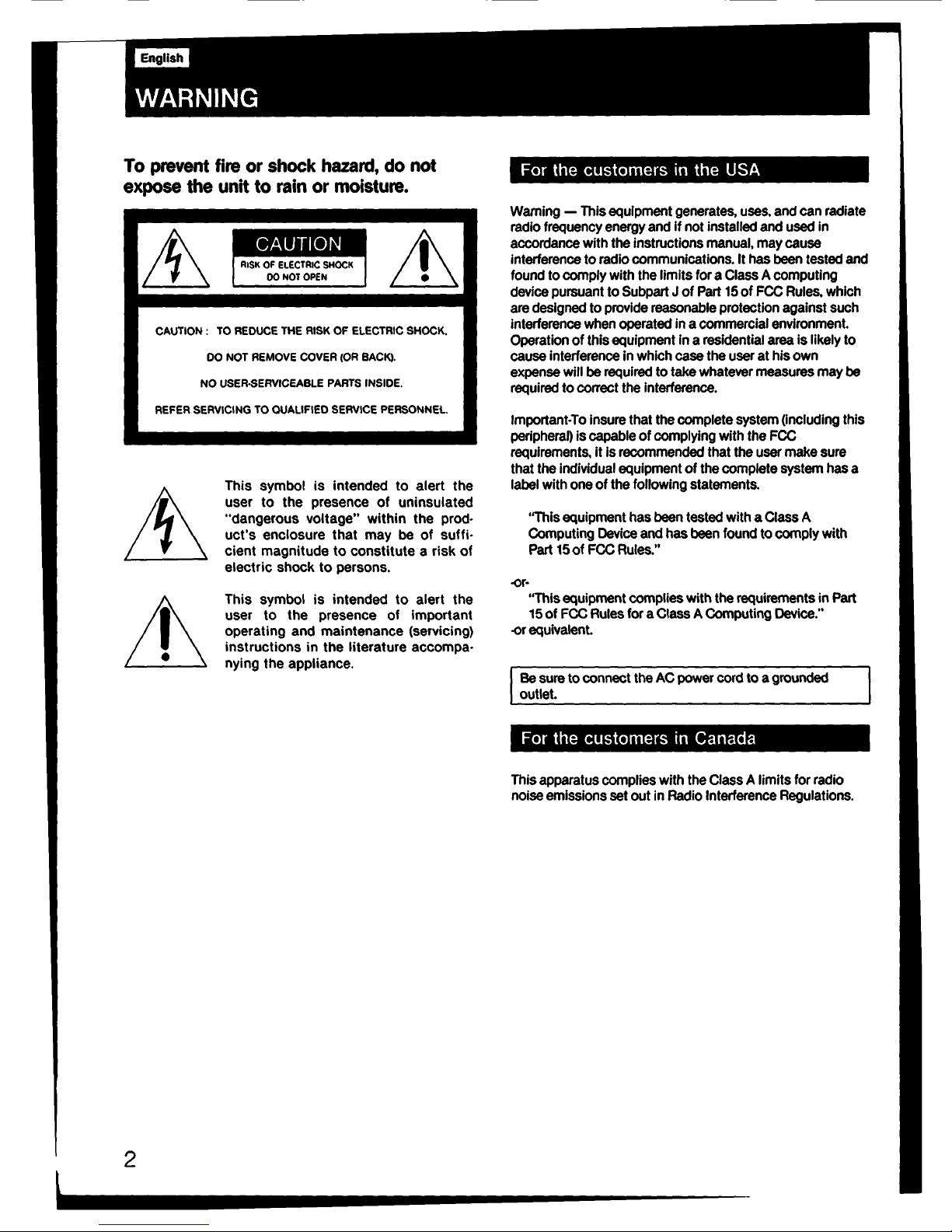
To prevent fire or shock hazard, do not
expose the unit to rain or moisture.
2
CAUTION
RISK OF ELECTRIC SHOCK
OONOTOPEN
CAUTION : TO REDUCE THE RISK OF ELECTRIC SHOCK.
DO NOT REMOVE COVER (OR BACK).
NO USER-SERVICEABLE PARTS INSIDE.
REFER SERVICING TO QUALIFIED SERVICE PERSONNEL
This symbol is intended to alert the
user to the presence of uninsulated
"dangerous voltage" within the prod•
uct's enclosure that may be of suffi•
cient magnitude to constitute a risk of
electric shock to persons.
This symbol is intended to alert the
user to the presence of important
operating and maintenance (servicing)
instructions in the literature accompa•
nying the appliance.
For the customers in the USA
Warning - This equipment generates, uses. and can radiate
radio frequency energy and If not installed and used In
accordance with the instructions manual, may cause
interference to radio communications. It has been tested and
found to comply with the limits for a Class A computing
device pursuant to Subpart J of Part 15 of FCC Rules, which
are designed to provide reasonable protection against such
interference when operated in a commercial environment.
Operation of this equipment in a residential area is likely to
cause interference in which case the user at his own
expense will be required to take whatever measures may be
required to correct the interference.
Important-To insure that the complete system (including this
periphera0 is capable of complying with the FCC
requirements, it is recommended that the user make sure
that the individual equipment of the complete system has a
label with one of the following statements.
"This equipment has been tested with a Class A
Computing Device and has been found to comply with
Part 15of FCC Rules."
-or-
"This equipment complies with the requirements in Part
15 of FCC Rules for a Class A Computing Device."
-or equivalent.
Be sure to connect the AC power cord to a grounded
outlet.
I
For the customers in Canada
This apparatus complies with the Class A limits for radio
noise emissions set out in Radio Interference Regulations.
Table of Contents
Precautions ....................................................................................... 3
Features ...................................................... ·---·· .. ······........... 4
Location and function of parts and controls ........................... 6
Front panel ................................................................................... 6
Rear panel .................................................................................... 10
Specifications ................................................................................... 13
Attaching the indication number ........................................... 15
Precautions
On safety
• Operate the unit only on 120 V AC.
• Should any solid object or liquid fall into the cabinet,
unplug the unit and have it checked by qualified personnel
before operating it any further.
• Unplug the unit from the wall outlet if It is not to be used for
several days or more.
• To disconnect the AC power cord, pull it out by grasping
the plug. Never pull the cord itself.
On lnstaHatlon
• Allow adequate air circulation to prevent internal heat
build-up.
Do not place the unit on surfaces (rugs, blankets, etc.) or
near materials (curtains, draperies) that may block the
ventilation holes.
• Do not install the unit in a location near heat sources such
as radiators or air ducts, or in a place subject to direct
sunlight, excessive dust, mechanical vibration or shock.
On deaning
To keep the unit looking brand•new, periodically clean it with
a soft cloth. Stubborn stains may be removed with a cloth
lightly dampened with a mild detergent solution. Never use
strong solvents such as thinner or benzine, or abrasive
cleansers since these will damage the cabinet. As a safety
precaution, unplug the unit before cleaning it.
On repacking
Do not throw away the carton and packing materials. They
make an ideal container In which to transport the unit. When
shipping the unit to another location, repack it as illustrated
on the carton.
If you have any questions about this unit, contact your
authorized Sonv dealer.
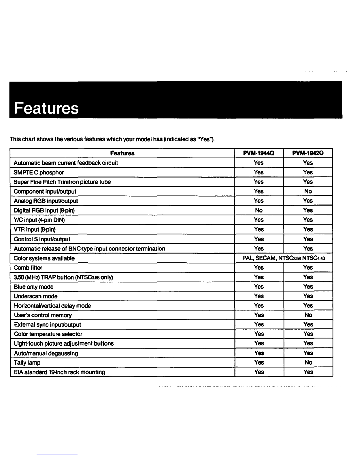
Features
This chart shows the various features which your model has (Indicated as "Yes'1.
Features
PVM-19440 PVM•1942Q
Automatic beam current feedback circuit Yes Yes
SMPTE C phosphor
Yes Yes
Super Fine Pitch Trlnitron picture tube
Yes
Yes
Component input/output
Yes No
Analog RGB input/output
Yes Yes
Digital RGB input (9-pin) No
Yes
Y/C input (4-pin DIN)
Yes Yes
VTR input (8-pin) Yes Yes
Control S Input/output Yes Yes
Automatic release of BNC-type input connector termination Yes Yes
Color systems available
PAL, SECAM, NTSC3.58 NTSC4 . .c3
Comb filter
Yes Yes
3.58 (MHZ) TRAP button (NTSC3.58 only)
Yes Yes
Blue only mode
Yes Yes
Underscan mode
Yes Yes
Horizontal/vertical delay mode
Yes Yes
User's control memory
Yes No
External sync Input/output
Yes Yes
Color temperature selector
Yes Yes
Light-touch picture adjustment buttons
Yes Yes
Auto/manual degaussing
Yes Yes
Tally lamp Yes
No
EIA standard 19-inch rack mounting
Yes Yes
Automatic beam cu1Tent feedback circuit
The automatic beam current feedback circuit compensates
for the beam distortion, secular distortion of the cathode-ray
tube, etc., and always reproduces the same white display on
the screen. This allows an extended use of the monitor.
Super Fine Pitch Trinltron picture tube
The Super Fine Pitch Trlnltron picture tube (0.4 mm aperture
grill) gives high resolution picture. Horizontal resolution Is
more than 6001V lines at the center of the picture. When
used as a character display, up to 2,000 characters (80
characters/line x 25 lines) can be displayed with great clarity.
Analog RGB/component connector (PVM-19440 only)
Analog RGB and component signals of a video equipment
can be Input through this connector. The signals are
selected by the COMPO/RGB selector on the rear panel.
Analog RGB connector (PVM-19420 only)
Analog RGB signal of a video equipment can be input
through this connector.
Digital RGB input connector (PVM-19420 only)
Digital RGB signal from a microcomputer can be Input
through this connector.
VIC input connector
The video signal split Into the chromlnance signal (C) and the
luminance signal (Y) can be Input through this connector,
eliminating the Interference between the two signals which
tends to occur In a composite video signal and assuring the
video quality.
VTR input connector
When connected to a VTR having the 8-pin 1V connector,
video and audio signals can be fed through this connector
with a single cable.
Control S connector
When this connector Is connected to the "control S" output
of other equipment, the remote controls of the aperture,
brightness, chroma, phase, contrast and volume settings are
possible.
Automatic release of BNC-type connector termination
The BNCtype Input connector Is terminated at 75 ohms
Inside when the BNCtype output connector Is open. When a
cable Is connected to the BNCtype output connector, the
75-ohm termination Is automatically released, and the signal
Input through the IN connector Is output from the
corresponding OUT connector.
Four color systems available
The monitor can display PAL, SECAM, NTSC3.5B and
NTSC.1.43• signals. The appropriate color system is selected
automatically.
• A signal of NTSC4.43 is obtained by playing back NTSC·
recorded video cassettes with a video tape recorder/player
espec\a\\~ des\gned tor use w\th th\s system.
3.58 (MHz) TRAP button (NTSCasa only)
This button can be used to eliminate the dot interference to
the luminance signal appearing between colors In the
horizontal direction, which Is one of the characteristics of the
comb filter.
Comb filter
When NTSC video signals are received, a comb filter
activates to increase the resolution, resulting in fine picture
detail without color spill or color noise.
Blue only mode
In the blue only mode, an apparent monochrome display is
obtained with all three cathodes driven with a blue signal.
This facilitates color saturation and phase adjustments and
observation of VTR noise.
Underscan mode
The signal normally scanned outside of the screen can be
monitored In the underscan mode.
-
The bright scanning lines which may appear on the top edge
of the screen when the monitor is In the underscan mode are
caused by an internal test signal, rather than the input signal.
Horizontal/vertical delay mode
The horizontal and vertical sync signals can be checked
simultaneously in the HN delay mode.
User's control merno,y (PVM-19440 only)
The desired aperture, brightness, chroma, and phase levels
can be memorized.
External sync input
When the EXT SYNC (or ANALOG/DIGIT AL (EXT SYNC))
button is depressed, the monitor can be operated on the
sync signal supplied from an external sync generator.
Color temperature selector
Color temperature of either 9,300°K or 6,500°K is selectable
with the COLOR TEMP selector. For precise adjustment, use
the BIAS and GAIN adjustment controls.
Light-touch picture adjustment buttons
The aperture, brightness, chroma, phase, contrast and
volume buttons can be adjusted by touching the buttons
lightly. The adjusted settings will be stored In memory even
when the monitor is turned off.
Auto/manual degaussing
Degaussing of the screen can be performed automatically
when the power is turned on, or manually by pressing the
DEGAUSS button.
EIA standard 19-inch rack mounting
By using an optional SLR101 slide rail, the monitor can be
mounted in an EIA standard 19-inch rack. For details on
mounting, see the appropriate Instruction manual.
5
Location and Function of Parts and Controls
Front panel
PVM-19440
Front panel
PVM-19420
rr----------:
I I
I
[ 1 :::: 1_6888888 ~:
R
[I]Tally lamp
Lights up when the video camera connected to this unit is
selected, indicating that the picture is being recorded. The
indication number can be attached on the lamp using the
supplied sheets (see page 15).
(I] DEGAUSS button
Press this button momentarily. The screen will be
demagnetized for approximately 5 seconds. Wait for 10
minutes or more before activating this button again.
[!] 3.58 TRAP button (NTSC3.58 only)
Normally set this button in released position (.c. OFF) to
obtain fine picture detail without color spill or color noise.
When a microcomputer, such as APPLE II, Is connected
and stripes appear, depress this button (= ON).
[IJ Color system Indicators
The indicator of the color system being received lights up
In red.
III INPUT select buttons
Press to select the program to be monitored.
k. for a signal fed through the LINE A connectors.
8: for a signal fed through the LINE B connectors.
Y/CNTR: for a signal fed through the Y/C-INPUT
connectors or VTR connector.
When both the VIC-INPUT and VTR connectors are
connected to video equipment, the input signal fed
through the Y/C-INPUT connector has priority over the
one fed through the VTR connector.
ANALOG RGB/COMPONENT: for a signal fed through
the ANALOG RGB/COMPONENT connectors.
For connection, refer to the explanation of ANALOG
RGB/COMPONENT connectors on page 11.
II] BLUE ONLY button
Depress to tum off the red and green signals. A blue
signal is displayed as an apparent monochrome picture
on the screen. This facilitates "chroma" and "phase•"
control adjustments and observation of VTR noise.
• uPhase" control adjustment Is effective only for the NTSC signals.
[II UNDER SCAN button
Depress for underscanning. The display size is reduced by
approximately 3% so that four comers of the raster are
visible.
II) H-V DELAY button
Depress to observe the horizontal and vertical sync
signals at the same time.
The horizontal sync signal is displayed In the left quarter
of the screen; the vertical signal is displayed near the
center of the screen.
[II EXT SYNC (extemal sync) button
Normally keep this button released (INl). The monitor
operates on the sync signal from the displayed composite
video signal.
To operate the monitor on an external sync signal fed
through the EXT SYNC connector on the rear panel,
depress the button (EXl).
11!1 BIAS and GAIN adjustment controls
Used for white balance adjustment.
Gain and BIAS controls are provided for the R (red), G
(green) and B (blue) screens.
BIAS: Adjust the white balance and brightness of the
screen at the lowlight with these controls.
GAIN: Adjust the white balance and contrast of the
screen at the highlight with these controls.
Ill] Response Indicator
Flashes when the MEMORY (PVM-19440 only), RESET,
APERTURE, BRIGHT, CHROMA, PHASE, CONTRAST, or
VOL button is pressed.
[lll MEMORY button and RESET button
After setting the APERTURE, BRIGHT, CHROMA, and
PHASE controls to the desired levels, press the MEMORY
button with a pencil or a similar object so that these
levels can be memorized and the response indicator lights
up.
When the RESET button is pressed, the above control
settings, and not the factory set levels, will be restored.
To change the memorized levels, repeat the above
operations.
To release the memorized levels and restore the factory
set levels, while pressing the MEMORY button, press the
RESET button.
fi1I APERTURE buttons
Press+ for more sharpness or - for less.
IHI BRIGHT (brightness) buttons
Press+ for more brightness or - for less.
7
Location and Function of Parts and Controls
[iID CHROMA buttons
Press+ for more color intensity or - for less.
[1§1 PHASE buttons
This button Is effective only for the NTSC3.58 and NTSC4.43
color system.
Press GAN (green) to make the skin tones greenish or
PUR (purple) to make them purplish.
-
The APERTURE, CHROMA, PHASE control settings have
no effect on the pictures of analog RGB or digital RGB
signals.
li1J CONTRAST buttons
Press+ to make the contrast, color intensity and
brightness stronger or - to make them weaker.
Iii] VOL (volume) buttons
Press+ for more volume or - for less.
ID] POWER switch and indicator
Depress to tum the monitor on.
The indicator will light up In green.
Press the switch again to tum the monitor off.
8
!iDI INPUT select buttons
Press to select the program to be monitored.
A:. for a signal fed through the LINE A connectors.
B: for a signal fed through the LINE B connectors.
Y/CNTR: for a signal fed through the VIC-INPUT
connectors or VTR connector.
When both the VIC-INPUT and VTR connectors are
connected to video equipment, the Input signal fed
through the VIC-INPUT connector has priority over the
one fed through the VTR connector.
RGB: for a signal fed through the ANALOG RGB
connectors or DIGITAL RGB connector.
lnJ ANALOG/DIGIT AL (EXT SYNC) button
This button functions as ANALOG/DIGITAL selector and
EXT SYNC selector.
As ANALOG/DIGITAL selector
Depress to monitor a signal fed through the ANALOG
RGB connectors.
Release to monitor a signal fed through the DIGITAL RGB
connector.
For EXT SYNC selector
Depress to operate the monitor on an external sync signal
fed through the EXT SYNC connector on the rear panel
(EXl).
Release to operate the monitor on the sync signal from
the displayed composite video signal (INT).
~
RESET button
Press to return the PHASE, CHROMA. BRIGHT and
APERTURE control settings to the factory set levels.
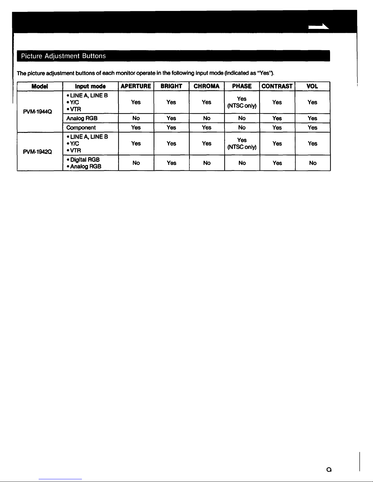
Picture Adjustment Buttons
The picture adjustment buttons of each monitor operate in the following input mode Qndicated as "Yes'1.
Model Input mode
APERTURE BRIGHT CHROMA PHASE CONTRAST
VOL
• LINE A, LINE B
Yes
•Y/C
Yes Yes Yes
(NTSConly)
Yes Yes
PVM-1944Q
•VTR
AnalogRGB
No Yes No No
Yes Yes
Component Yes Yes Yes No
Yes
Yes
•LINEA, LINE B
Yes
•Y/C
Yes Yes Yes
(NTSConly)
Yes
Yes
PVM-19420
•VTR
• Digital RGB
No
Yes No No Yes No
•AnalogRGB
a
 Loading...