

Sony Trinitron PVM-14L2MD,Trinitron PVM-20L2MD Instructions For Use Manual
4-096-453-04 (1)
Trinitron®
Color Video Monitor
取扱説明書 2 ページ _____________________________________
Instructions for Use page 18 _______________________________
Mode d’emploi page 32 ___________________________________
Gebrauchsanweisung seite 48 _____________________________
Manual de instrucciones página 64 __________________________
Instruzioni per l’uso pagina 80 ______________________________
______________________________________
電気製品は安全のための注意事項を守らないと、
火災や人身事故になることがあります。
この取扱説明書には、事故を防ぐための重要な注意事項と製品の取り扱いかたを示してあり
ます。この取扱説明書をよくお読みのうえ、製品を安全にお使いください。お読みになった
あとは、いつでも見られるところに必ず保管してください。
JP
GB
FR
DE
ES
IT
CS
PVM-14L2MD
PVM-20L2MD
© 2003 Sony Corporation
安全のために
ソニーのモニターは正しく使用すれば事故が起きないよ
うに、安全には十分配慮して設計されています。しかし、
内部に非常に高い電圧を使用しているので、まちがった
使いかたをすると、火災や感電などにより死亡や大けが
など人身事故につながることがあり、危険です。
事故を防ぐために次のことを必ずお守りください。
安全のための注意事項を守る
4 〜 6 ページの注意事項をよくお読みください。製品全
般の安全上の注意事項が記されています。
7 ページの「使用上のご注意」もあわせてお読みくださ
い。
定期点検をする
5 年に 1 度は、内部の点検を、お買い上げ店またはソ
ニーのサービス窓口にご依頼ください(有料)。
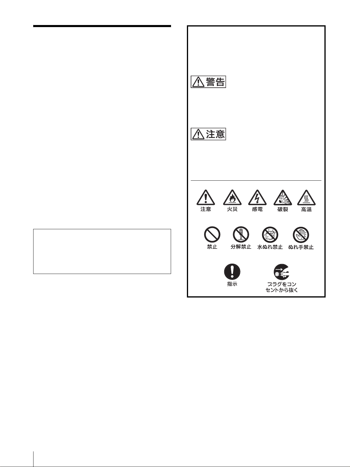
警告表示の意味
この取扱説明書および製品では、次のような表示
をしています。表示の内容をよく理解してから本
文をお読みください
この表示の注意事項を守らないと、火災や感電な
どにより死亡や大けがなど人身事故につながるこ
とがあります。
この表示の注意事項を守らないと、感電やその他
の事故によりけがをしたり周辺の物品に損害を与
えたりすることがあります。
故障したら使わない
すぐに、お買い上げ店またはソニーのサービス窓口にご
連絡ください。
万一、異常が起きたら
・ 煙が出たら
・ 異常な音、においがしたら
・ 内部に水、異物が入ったら
・ モニターを落としたり、キャビネットを破損し
たときは
a 電源を切る。
b 電源コードや接続ケーブルを抜く。
c お買い上げ店またはソニーのサービス窓口に連絡す
る。
注意を促す記号
行為を禁止する記号
行為を指示する記号
2
目次
使用上のご注意(モニターの性能を保持するために) .... 7
磁気に対するご注意 ..............................................7
ブラウン管について ..............................................7
クリーニングについて...........................................7
ラックマウントについて .......................................7
特長 ................................................................................................7
接続 ................................................................................................8
電源コードの取り付けかた ...................................8
各部の名称と働き....................................................... ................9
操作パネル ............................................................9
後面パネル ......................................................... 10
メニュー表示言語の切り換え .............................................. 11
メニューの操作方法 ...............................................................12
メニューを使った調整 ........................................................... 13
項目一覧....... .............. ............... ............... .......... 13
調整と設定 ......................................................... 13
設定状態メニュー..................................... 13
ホワイトバランスメニュー ...................... 14
プリセットメニュー................................. 14
ユーザー設定(1/2、2/2)メニュー ...... 14
リモートメニュー..................................... 14
ユーザーサービスメニュー ...................... 15
故障かな?と思ったら ........................................................... 15
保証書とアフターサービス...................................................15
保証書 ................................................................ 15
アフターサービス............................................... 15
主な仕様.......... ...........................................................................16
寸法図 ........................................................... i
この取扱説明書について
本書は、以下のカラービデオモニターに共通のもので
す。
・ PVM‑14L2MD(14 インチモニター)
・ PVM‑20L2MD(20 インチモニター)
上記機種で説明が異なる場合は、別々に説明してありま
すので該当する部分をお読みください。
本書のイラストは、特に表示のない場合すべて PVM‑
14L2MD を使用しています。
この装置は、クラス A 情報技術装置です。この装置を家
庭環境で使用すると電波妨害を引き起こすことがありま
す。この場合には使用者が適切な対策を講ずるよう要求
されることがあります。
JP
電源接続時のご注意
それぞれの地域に合った電源コードをお使いください。
アメリカ合衆国 カナダ ヨーロッパ諸国 日本
プラグ型名 HOSPITALGRADE HOSPITALGRADE LP‑34A VM1050
コネクタ型名 E41395 LL33182 LS‑60 VM1010
コード型名 E41395‑A LL76662 H05VV‑F PVCTF
定格電圧・電流 10A/125V 10A/125V 10A/250V 12A/125V
コード長 Max.4.5m(1771/
安全規格 UL CSA VDE 電安法
in.) Max.4.5m(1771/4in.) − −
4
3
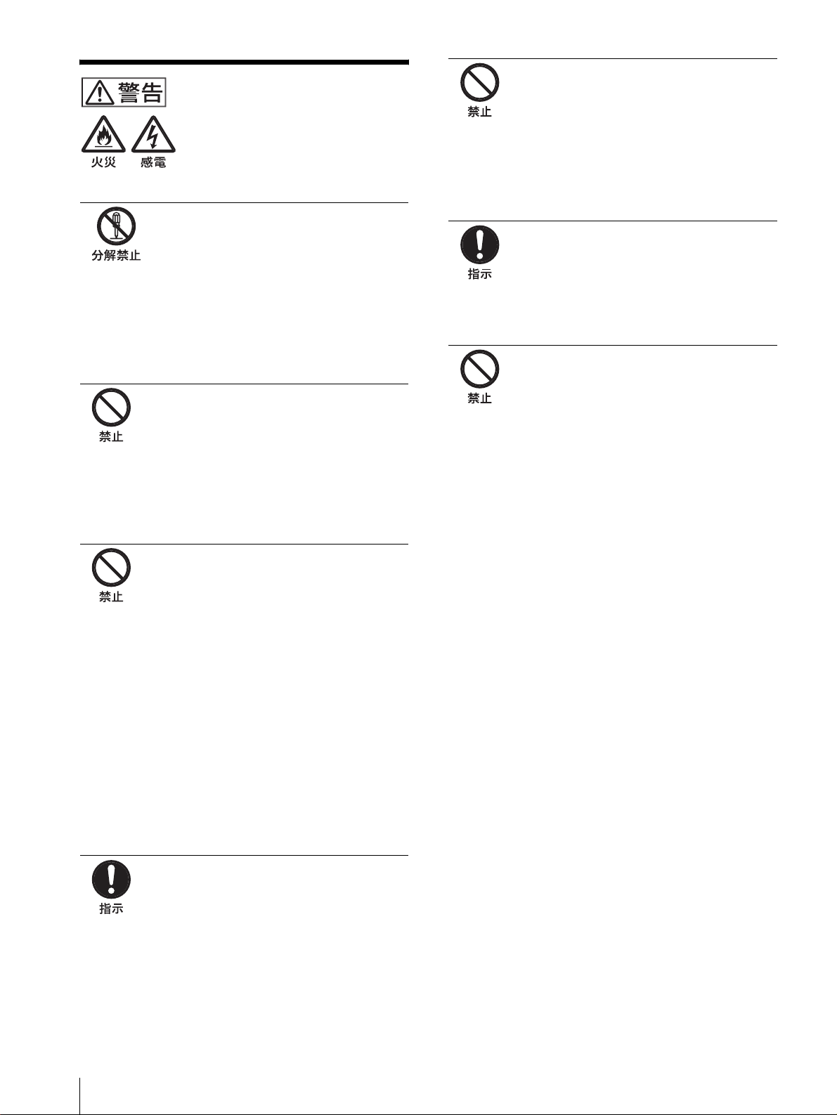
下記の注意を守らないと、火災
や感電で大けがにつながるこ
とがあります。
キャビネットをはずさない、改造し
ない
内部には電圧の高い部分があり、キャビ
ネットや裏ぶたなどをはずしたり、改造し
たりすると、火災や感電の原因となります。
内部の調整や設定、点検、修理は、お買い
上げ店またはソニーのサービス窓口にご依
頼ください。
内部に水や異物を入れない
水や異物が入ると火災や感電の原因となり
ます。
万一、水や異物が入ったときは、すぐに電
源を切り、電源コードや接続ケーブルを抜
いて、お買い上げ店またはソニーのサービ
ス窓口にご相談ください。
油煙、湯気、湿気、ほこりの多い場
所では設置・使用しない
上記のような場所に設置すると、火災や感
電の原因となります。
この取扱説明書に記されている仕様条件以
外の環境での使用は、火災や感電の原因と
なります。
ラックマウント時は専用ブレーカー
を取り付ける
ラックマウント時は前面より電源を切るこ
とができません。設置の際は専用ブレー
カーを取り付けて使用してください。
ラックマウントした機器を、2 台以
上同時に引き出さない
2 台以上同時に引き出すと、機器の重みで
ラックが転倒し、けがの原因となります。
一度にラックから引き出すのは 1 台だけに
してください。
また、ラックが転倒・移動しないように適
切な処置をとってください。
電源コードを傷つけない
電源コードを傷つけると、火災や感電の原
因となります。
・ 設置時に、製品と壁やラック、棚などの
間に、はさみ込まない。
・ 電源コードを加工したり、傷つけたりし
ない。
・ 重いものをのせたり、引っ張ったりしな
い。
・ 熱器具に近づけたり、加熱したりしない。
・ 電源コードを抜くときは、必ずプラグを
持って抜く。
万一、電源コードが傷んだら、お買い上げ
店またはソニーのサービス窓口に交換をご
依頼ください。
規定の電源電圧で使う
取扱説明書に記されている電源電圧でお使
いください。
規定外の電源電圧での使用は、火災や感電
の原因となります。
4
下記の注意を守らないと、けが
をしたり周辺の物品に損害を与
えることがあります。
ぬれた手で電源プラグをさわらない
ぬれた手で電源プラグを抜き差しすると、
感電の原因となることがあります。
接続の際は電源を切る
電源コードや接続ケーブルを接続するとき
は、電源を切ってください。感電や故障の
原因となることがあります。
直射日光の当たる場所や熱器具の近
くに設置・保管しない
内部の温度が上がり、火災や故障の原因と
なることがあります。
真夏の、窓を閉め切った自動車内では 50
℃を越えることがありますので、ご注意く
ださい。
モニターは、2 人以上で開梱・運搬
する
モニターは見た目より重量があります。開
梱や運搬は、けがや事故を防ぐため、必ず
2 人以上で行ってください。1 人で行うと
腰を痛めることがあります。
指定された電源コード、接続ケーブ
ルを使う
付属の、あるいは取扱説明書に記されてい
る電源コード、接続ケーブルを使わないと、
感電や故障の原因となることがあります。
他の電源コードや接続ケーブルを使用する
場合は、お買い上げ店またはソニーのサー
ビス窓口にご相談ください。
通風孔をふさがない
通風孔をふさぐと内部に熱がこもり、火災
や故障の原因となることがあります。風通
しをよくするために次の項目をお守りくだ
さい。
・ 壁から 10cm 以上離して設置する。
・ 密閉された狭い場所に押し込めない。
・ 毛足の長い敷物(じゅうたんや布団など)
の上に設置しない。
・ 布などで包まない。
・ あお向けや横倒し、逆さまにしない。
転倒、移動防止の処置をする
モニターをラックに取り付け・取りはずし
をするときは、転倒・移動防止の処置をし
ないと、倒れたり、動いたりして、けがの
原因となることがあります。安定した姿勢
で注意深く作業してください。
また、ラックの設置状況、強度を充分にお
確かめください。
モニターの上に乗らない、重いもの
を載せない
倒れたり、落ちたり、壊れたりして、けが
の原因となることがあります。
お手入れの際は、電源を切って電源
プラグを抜く
電源を接続したままお手入れをすると、感
電の原因となることがあります。
水のある場所に設置しない
水が入ったり、ぬれたりすると、火災や感
電の原因となることがあります。雨天や降
雪中、海岸や水辺での使用は特にご注意く
ださい。
不安定な場所に設置しない
ぐらついた台の上や傾いたところなどに設
置すると、モニターが落ちたり、倒れたり
して、けがの原因となることがあります。
また、設置・取り付け場所の強度を充分に
お確かめください。
5
下記の注意を守らないと、けが
をしたり周辺の物品に損害を与
えることがあります。
移動させるときは電源コード、接続
ケーブルを抜く
接続したまま移動させると、電源コードや
接続ケーブルが傷つき、火災や感電の原因
となることがあります。
定期的に内部の掃除を依頼する
長い間掃除をしないと内部にホコリがたま
り、火災や感電の原因となることがありま
す。1 年に 1 度は、内部の掃除をお買い上
げ店またはソニーのサービス窓口にご依頼
ください(有料)。
特に、湿気の多くなる梅雨の前に掃除をす
ると、より効果的です。
電源プラグは突きあたるまで差し込
む
まっすぐに突きあたるまで差し込まないと、
火災や感電の原因となります。
安全アースを接続する
安全アースを接続しないと、感電すること
があります。
次の方法でアースを接続してください。
指定の電源コードから出ている緑色のアー
ス線を建物に備えられているアース端子に
接続してください。
安全アースを取りつけることができない場
合は、ソニーのサービス担当者または営業
担当者にご相談ください。
6

使用上のご注意(モニターの
特長
性能を保持するために)
磁気に対するご注意
・ 磁気を発生するものを近づけないでください。画面が揺
れたり、色が乱れたりすることがあります。
・ モニターの設置の向きによっては、画面が傾いたり、色
が乱れることがありますが、故障ではありません。この
ときは、一度電源を切り、再び電源を入れてください。
自動消磁されます。または操作パネルの DEGAUSS
(消磁)ボタンを押して消磁することもできます。
◆ DEGAUSS ボタンについて詳しくは、9 ページの
qfDEGAUSS ボタンをご覧ください。
ブラウン管について
・ 柔らかいきれいな布で軽く拭いてください。手の油や指
紋などは水で薄めた中性洗剤溶液を含ませた柔らかい布
で拭いてください。
・ 表面は傷つきやすいので、硬いものでこすったり、たた
いたり、ものをぶつけたりしないでください。研磨剤を
含むもの、アルカリ系洗剤、アルコールやベンジン、シ
ンナーなどを含んだ溶剤は、表面を傷める原因になる恐
れがありますのでご使用にならないでください。
クリーニングについて
・ お手入れの際は、必ず電源を切って電源プラグを抜いて
ください。
・ キャビネットの汚れがひどいときは、水で 5 〜 6 倍に
薄めた中性洗剤液に柔らかい布をひたし、かたくしぼっ
てから汚れを拭きとります。このあと乾いた布でから拭
きしてください。
・ シンナーやベンジンなどの薬品類は、表面の仕上げを傷
めたり、表示が消えてしまうことがありますので、使用
しないでください。
ラックマウントについて
ラックマウント時は、モニターの性能維持のため上下に
1U 空けて、通気孔の確保や通気ファンの設置を行って
ください。
画像
解像度
1)
トリニトロン
600 本以上の画像が得られます。
くし形フィルター
くし形フィルターの採用により、NTSC 信号のクロスカ
ラー妨害(文字のまわりの虹)やカラーノイズ(色のに
じみ)をなくし、きめ細かで透明度の高い画像が得られ
ます。
ビームカレントフィードバック回路
長期間安定したホワイトバランスが得られます。
2 カラー方式
NTSC、PAL の 2 つのカラー方式に自動で切り換わりま
す。
管の採用により、中心部の解像度が
入力
アナログ RGB/ コンポーネント入力端子
ビデオ機器のアナログ RGB、コンポーネント信号を入力
できます。操作パネルの RGB/COMPONENT ボタンを
押してモニターします。
Y/C 入力端子(S 入力端子)
ビデオ機器などの映像信号を、輝度信号(Y)と色信号
(C)の 2 つに分離したまま入力できます。これにより、
色のにじみやちらつきの少ない、鮮明な画像が得られま
す。
拡張可能な入力機能
本機後面のオプションスロットに別売りの入力拡張用オ
プションボードを装着することで、入力系統を容易に拡
張できます。入力拡張用オプションボードは 1 枚のみ装
着できます。
外部同期信号入力端子
外部同期信号発生器などからの同期信号を入力できます。
メニュー画面の「RGB 設定」で「RGB / EXT」に設定
すると、外部同期で動作します(14 ページ参照)。
1)トリニトロンはソニー株式会社の登録商標です。
使用上のご注意(モニターの性能を保持するために)/特長
7
自動終端解放( マーク付きの端子)
後面の入力端子は、出力端子に何も接続していないとき
は、内部的に 75Ω で終端されています。出力端子にケー
ブルが接続されると、内部の終端が自動的に解放され、
入力端子に入力された信号が出力端子に出力されます
(ループスルー)。
接続
電源コードの取り付けかた
機能
オートクロマ・フェーズ機能を標準装備
色の濃さ(クロマ)や色相(フェーズ)を自動調整する
機能を標準装備しています。
オーバースキャンモード
画面サイズが約 20 パーセント拡大され、中央部分が見や
すくなります。
アンダースキャンモード
通常、画面外に走査されている信号まで画面に表示し、
画像全体をモニターすることができます。
ご注意
アンダースキャン時に、画面上端に赤緑青の走査線が見
えますが、これは本体内部の動作によるものです。
自動 / 手動消磁機能
ブラウン管は、電源投入時に自動的に消磁されます。ま
た、DEGAUSS ボタンを押すと手動で消磁できます。
電源投入後から、自動的に消磁されるまでの時間をメ
ニューで設定することもできます。
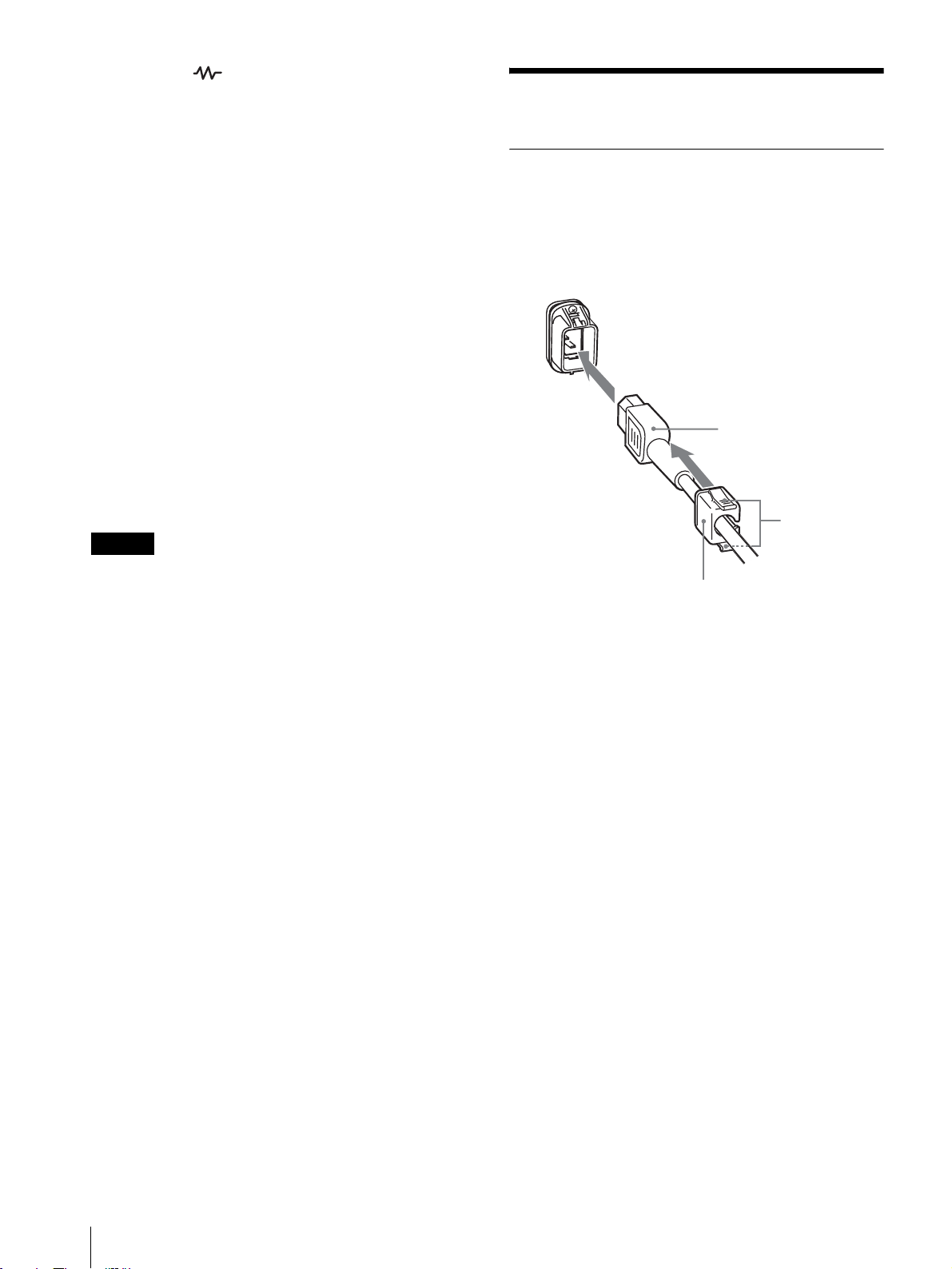
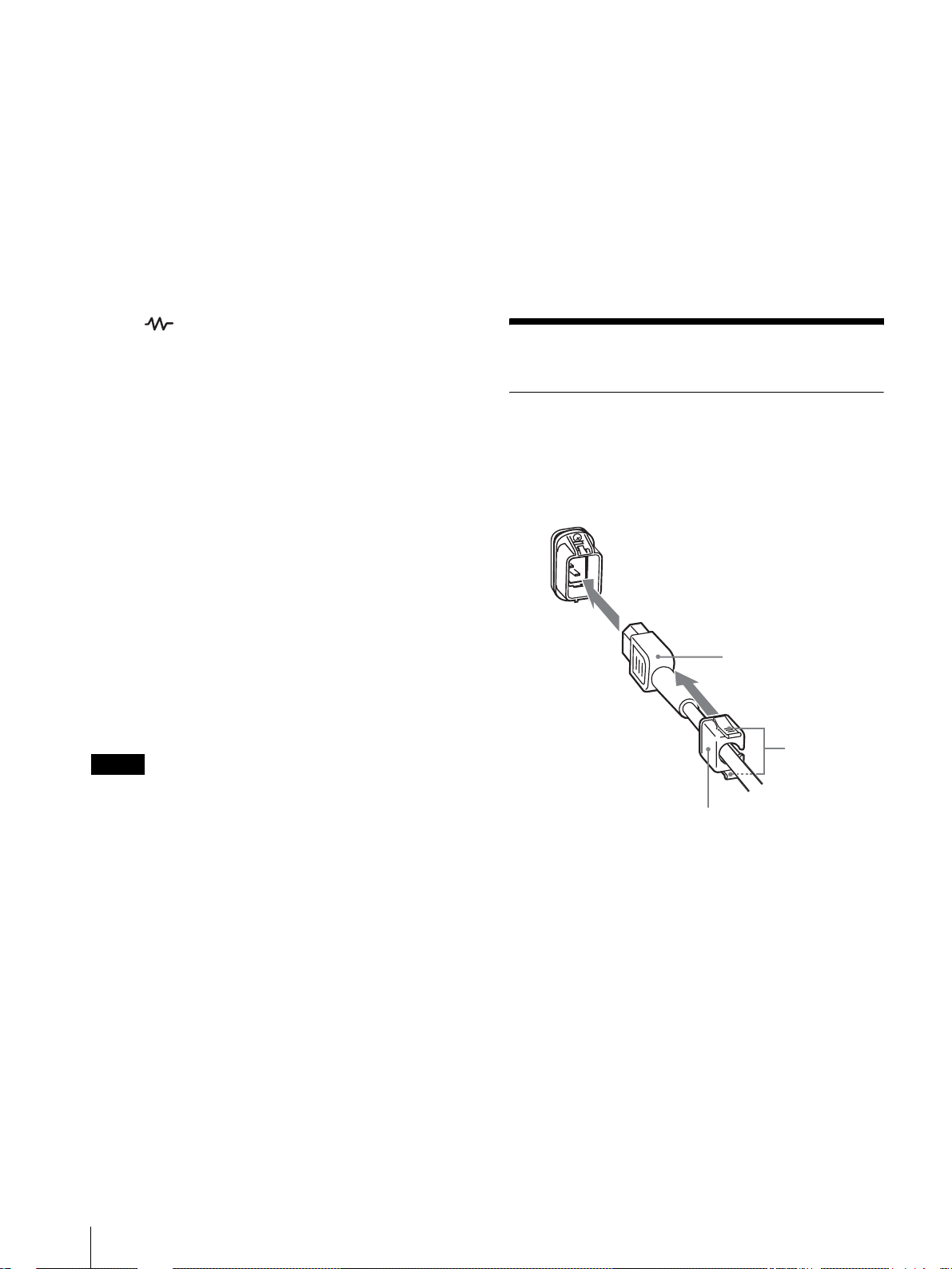
電源コードをつなぐには
AC 電源コードを後面の ACIN ソケットに差し込み、AC
電源プラグホルダーを AC 電源コードに取り付け、固定
レバーがロックするまではめ込みます。
ACIN ソケット
AC 電源コード
固定レバー
AC 電源プラグ
ホルダー
電源コードをはずすには
AC 電源プラグホルダーの固定レバーを両側からはさんで
ロックをはずし、引き抜きます。
スクリーンメニュー機能
画面にメニューを出して、接続するシステムに最適なモ
ニターの設定や調整をすることができます。
オプション
EIA 規格の 19 インチラックに収納可能
別売りのマウンティングブラケット MB‑502B(PVM‑
14L2MD 用)またはスライドレール SLR‑103A(PVM‑
20L2MD 用)を使用すると、EIA19 インチラックにマ
ウントすることができます。
◆マウント方法についてはマウンティングブラケットま
たはスライドレールの取扱説明書をご覧ください。
8
特長/接続
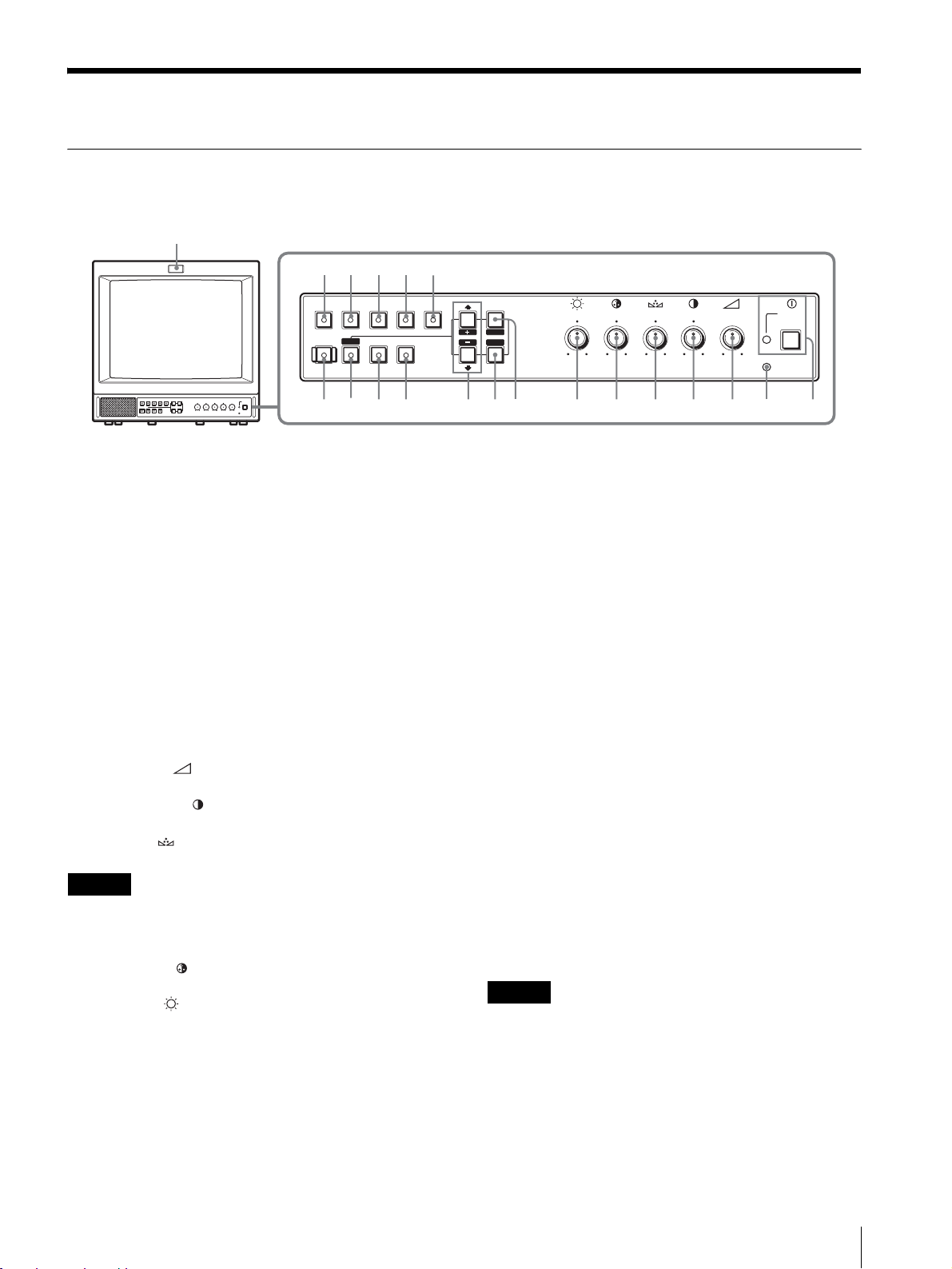
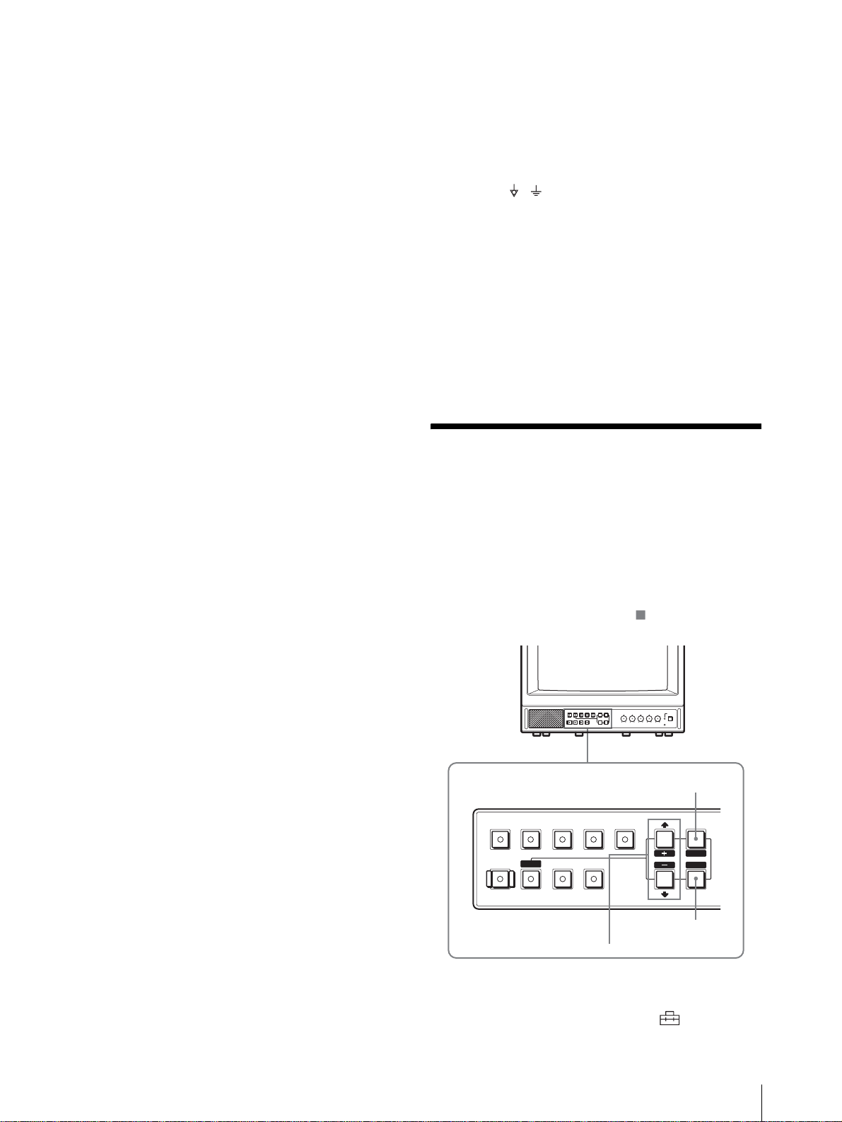
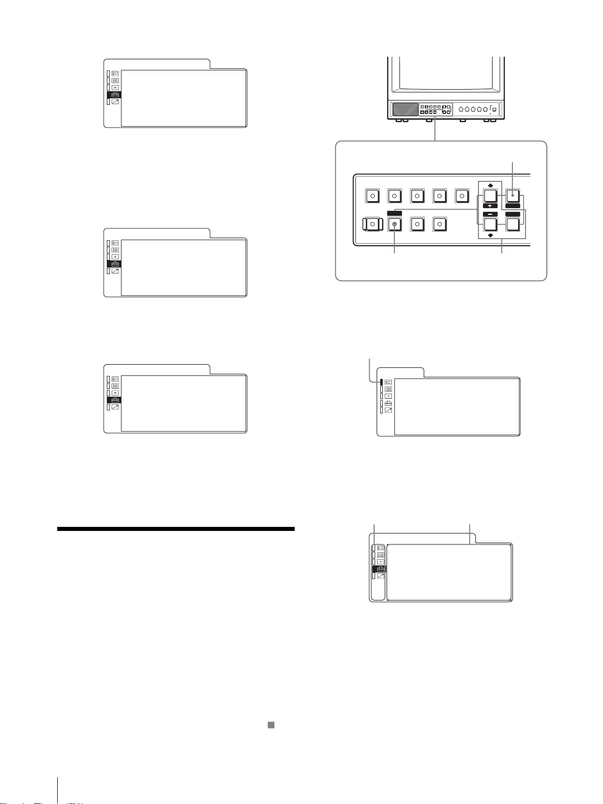
各部の名称と働き
w
操作パネル
;
DEGAUSS
LINEALINE
RESET
COMPONENT
B
RGB/
UNDER
SCAN
qkqjqhqg
OPTION
1
OVER
SCAN
ql
OPTION
2
MENU
EXIT
SELECT
ENTER
–+
PHASECHROMABRIGHT
MAX
MIN
PUR GRN MIN MAX MIN MAX
CONTRAST
VOLUME
POWER
REMOTE
134567890qa 2qsqdqf
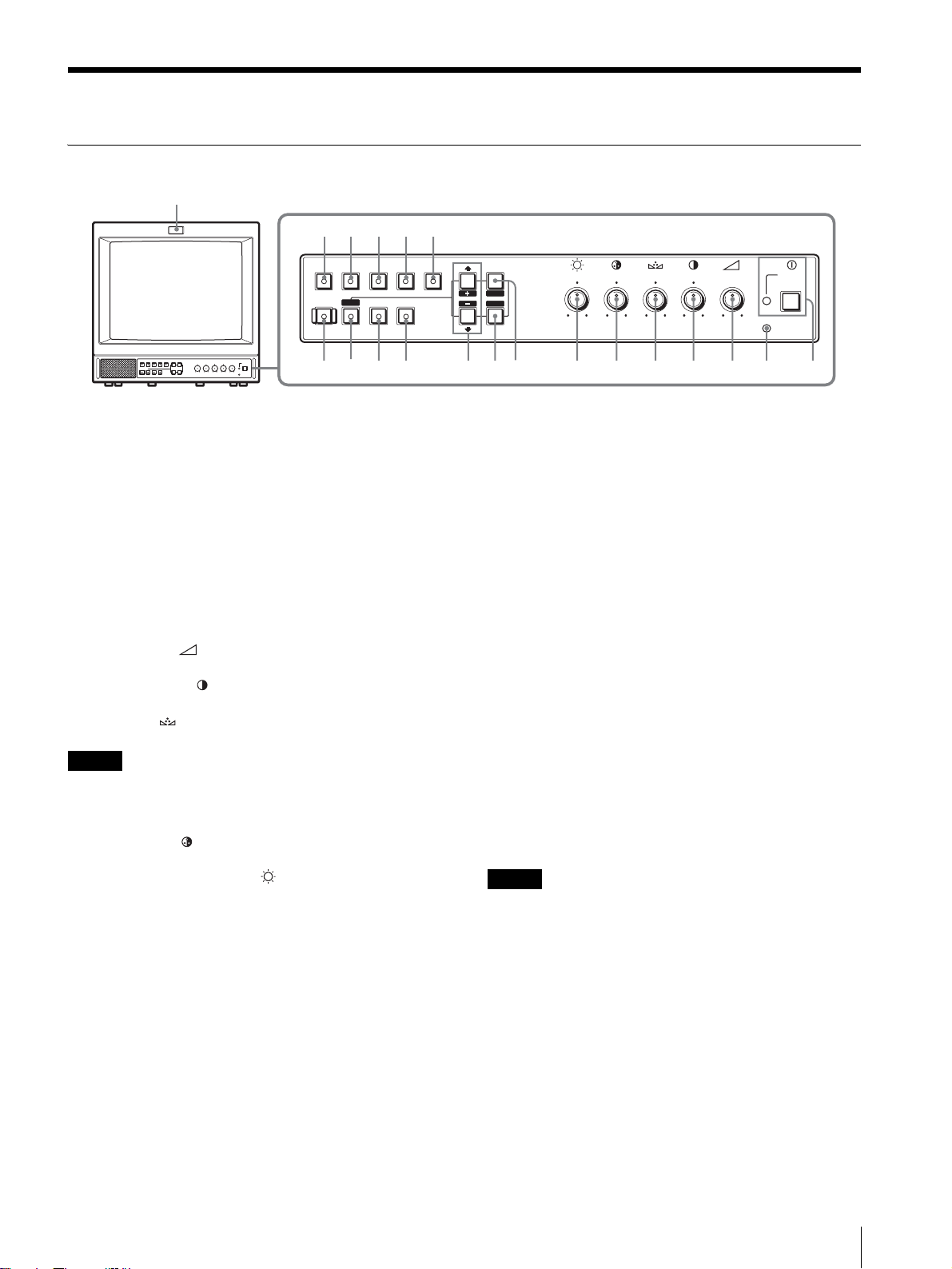
a POWER!(電源)スイッチとインジケーター
押し込むと電源が入り、インジケーターが点灯します。
もう一度押すと、電源が切れインジケーターが消灯しま
す。
b REMOTE(リモート)インジケーター
このインジケーターは、以下の場合に点灯します。
・ スクリーンメニューのプリセットメニューで、ON を選
択したとき。
・ スクリーンメニューのリモート(RS‑232C)メニュー
の、シリアルリモートを選び、リモートオンまたはリ
モート&ローカルを選択したとき。
c VOLUME (音量)調整つまみ
d CONTRAST 調整つまみ
e PHASE (色相)調整つまみ
ご注意
PAL、コンポーネントおよび RGB 信号では、色相
(フェーズ)の調整はできません。
f CHROMA (色の濃さ)調整つまみ
g BRIGHT (明るさ)調整つまみ
h MENU/EXIT ボタン
メニューを出したり消したりするときに使います。
i ENTER/SELECT ボタン
メニューで内容を決定するときに使います。
j M/+(カーソル上方向移動 / 調整)ボタン
m/–(カーソル下方向移動 / 調整)ボタン
メニューでカーソルを動かしたり、数値を調整したりす
るときに使います。
k OVERSCAN ボタンとインジケーター
押すとオーバースキャンモードになります。画面サイズ
が約 20%拡大され、中央部が見やすくなります。
もとの画面サイズに戻すときも、このボタンを押します。
l UNDERSCAN ボタンとインジケーター
押すとアンダースキャンモードになります。
画面サイズが約 5% 縮小され、画像の四隅まで表示され
ます。
もとの画面サイズに戻すときも、このボタンを押します。
m RESET ボタンとインジケーター
メニュー項目を調整中に押すと、調整が無効になり、調
整前の設定値に戻ります。
n DEGAUSS(消磁)ボタンとインジケーター
消磁したいとき、このボタンを 1 回押します。もう一度
使用するときは 10 分以上間隔をおいてください。
ご注意
スクリーンメニューが表示されている状態では、
DEGAUSS ボタンは効きません。
手動で消磁を行う場合は、MENU/EXIT ボタンでスク
リーンメニューを消してから行ってください。
各部の名称と働き
9
o LINEA ボタンとインジケーター
2134567
LINEA 入力端子からの信号をモニターするときに押しま
す。
オプションボードの入力1からの映像信号と OPTION
AUDIOINPUT1 からの音声信号をモニターするときに
押します。
p LINEB ボタンとインジケーター
LINEB 入力端子からの信号をモニターするときに押しま
す。
q RGB/COMPONENT ボタンとインジケーター
RGB/COMPONENT 入力端子からの信号をモニターす
るときに押します。
r OPTION1 ボタンとインジケーター
モニター後面のオプションスロットにオプションボード
が装着されているときに使用します。
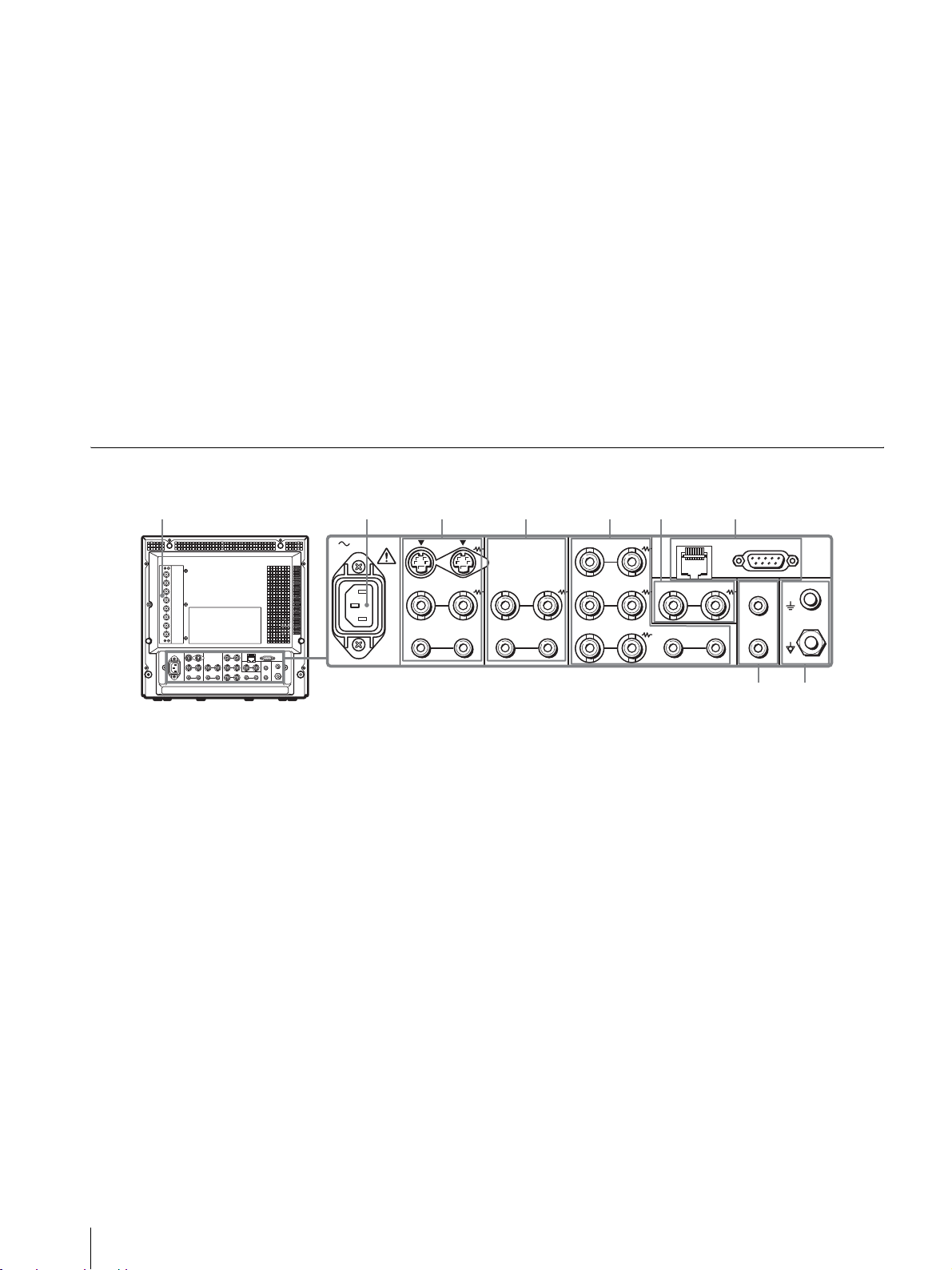
後面パネル
AC IN LINE A LINE B
IN OUT
VIDEO
IN
AUDIO
s OPTION2 ボタンとインジケーター
モニター後面のオプションスロットにオプションボード
が装着されているときに使用します。
オプションボードの入力 2 からの映像信号と OPTION
AUDIOINPUT2 からの音声信号をモニターするときに
押します。
t タリーランプ
本機に接続されているカメラの映像が選ばれると、ラン
プが点灯します。
◆タリーランプが点灯するようにするには、タリー制御
の配線が必要です。詳しくは 17 ページをご覧くださ
い。
REMOTE
RGB/COMPONENT
G/Y
IN OUT
VIDEO
IN
OUT
AUDIO AUDIO
OUT
IN OUT
B/PB
IN OUT IN
R/P
R
PARALLEL RS-232C
OUT
OPTION
AUDIO INPUT
1
2
IN OUT
EXT
SYNC
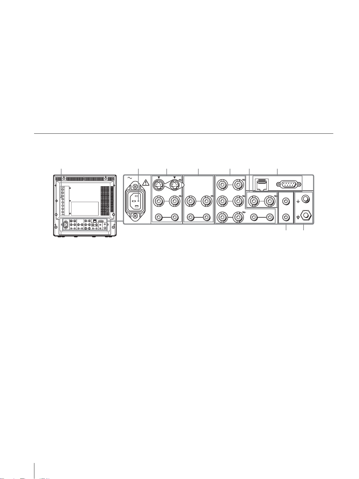
a OPTION(オプション)スロット(BKM‑129X)
別のオプションボードを使うときは、BKM‑129X を取り
外して装着しなおします。
RGB/COMPONENT 入出力端子・EXTSYNC(外部同
期)入出力端子
アナログ RGB またはコンポーネント(Y、PB、PR)信
号の入出力端子です。
操作パネルの OPTION1 ボタンを押してモニターしま
す。
音声は、OPTIONAUDIOINPUT 端子に接続してくだ
さい。
外部同期信号を使う場合は、メニューの「RGB 設定」の
「RGB / EXT」、「COMP / EXT」で設定します。
◆オプションボードは 1 枚のみ装着できます。2 枚装着
すると、機能しません。装着方法について詳しくは、オ
プションボードに付属の取扱説明書をご覧ください。
b ACIN ソケット
付属の AC 電源コードをつなぎます。
89
c LINEA 入出力端子
Y/C 分離入力、コンポジットビデオ信号と音声信号のラ
イン入力端子、およびそれぞれのループスルー端子です。
操作パネルの LINEA ボタンを押してモニターします。
Y/C 入力と VIDEO 入力を同時に接続した場合、Y/C 入
力が優先となります。
Y/CIN/OUT(4 ピンミニ DIN)
Y/C 分離の入出力端子です。VTR やビデオカメラ、他
のモニターなど、外部機器の Y/C 分離出力および入力
端子と接続します。
VIDEOIN/OUT(BNC 型)
コンポジットビデオの入出力端子です。VTR やビデオ
カメラ、他のモニターなど、外部機器のコンポジット映
像出力および入力端子と接続します。
AUDIOIN/OUT(ピンジャック)
音声の入出力端子です。VTR などの外部機器の音声出
力および入力端子と接続します。
10
各部の名称と働き
d LINEB 入出力端子
コンポジットビデオ信号と音声信号のライン入力端子、
およびそれぞれのループスルー端子です。
操作パネルの LINEB ボタンを押してモニターします。
VIDEOIN/OUT(BNC 型)
コンポジットビデオの入出力端子です。VTR やビデオ
カメラ、他のモニターなど、外部機器のコンポジット映
像出力および入力端子と接続します。
AUDIOIN/OUT(ピンジャック)
音声の入出力端子です。VTR などの外部機器の音声出
力および入力端子と接続します。
e RGB/COMPONENT 入出力端子
アナログ RGB またはコンポーネント(Y、P
の入力端子、およびそれぞれのループスルー出力端子で
す。
操作パネルの RGB/COMPONENT ボタンを押してモニ
ターします。
B、PR
)信号
RS‑232C(シリアルリモート)端子(D‑Sub9 ピン)
外部機器の RS‑232C コントロール端子に接続します。
接続された外部機器よりコントロールコマンドを送るこ
とで、モニターの操作を行うことができます。
◆詳しくはプログラマー用インターフェース解説書(別
冊)をご覧ください。
h アース( / )端子
アース線をこの端子に接続します。
i OPTIONAUDIO(オプションオーディオ)INPUT
1、2 入力端子
オプションスロットにオプションボードが装着されてい
る場合、その音声入力に使用する入力端子です。2 系統ま
で接続することができます。OPTIONAUDIOINPUT1
または 2 入力端子から入力した音声信号をモニターする
場合には、それぞれ OPTION1 または OPTION2 ボタ
ンを押します。
G/Y、B/P
アナログ RGB およびコンポーネント(Y、P
、R/PRIN/OUT(BNC 型)
B
B、PR
)の
入出力端子です。入力時は、通常 G/Y 信号に含まれて
いる同期信号で動作します。
AUDIOIN/OUT(ピンジャック)
映像信号としてアナログ RGB またはコンポーネントを
入力する場合に、音声信号の入出力端子として使用しま
す。VTR など、外部機器の音声出力および入力端子と
接続します。
f EXTSYNC(外部同期)入出力端子
外部同期信号を使う場合はメニュー画面の「RGB 設定」
の「RGB/EXT」に設定します。
IN/OUT(BNC 型)
外部同期信号の入出力端子です。IN 端子には外部同期
信号発生器などからの基準信号を入力します。OUT 端
子は、本機と同期して動作させる他のビデオ機器の外部
同期入力端子と接続します。
g REMOTE(リモート)端子
PARALLELREMOTE(パラレルリモート)端子(モ
ジュラージャック、8 ピン)
コントロールスイッチを構成してモニターを外部操作し
ます。
◆ピン配置と出荷時の各ピンへの機能の割り付けについ
て詳しくは、17 ページをご覧ください。
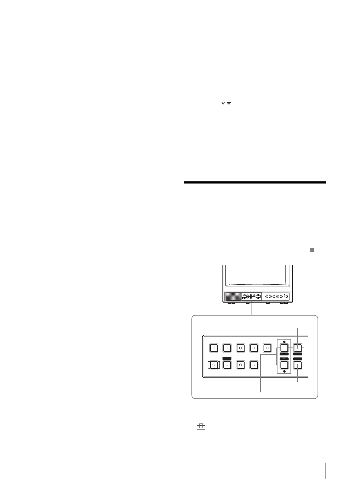
メニュー表示言語の切り
換え
メニュー画面やメッセージの表示言語を 7 言語
(ENGLISH、DEUTSCH、FRANÇAIS、ITALIANO、
ESPAÑOL、日本語、中文)の中から選ぶことができます。
出荷時の設定は「ENGLISH」(英語)に設定されていま
す。
なお、メニュー画面のイラスト上の マーク部分に、本
機の現在の設定値が表示されます。
MENU/EXIT ボタン
LINEALINE
B
RESET
DEGAUSS
M/+、m/– ボタン
RGB/
COMPONENT
UNDER
SCAN
OPTION
OPTION
2
1
OVER
SCAN
ENTER/SELECT ボタン
MENU
EXIT
SELECT
ENTER
1
MENU/EXIT ボタンを押し、メニュー画面が表示さ
れたら
M/+、m/– ボタンを押して (USER
各部の名称と働き/メニュー表示言語の切り換え
11
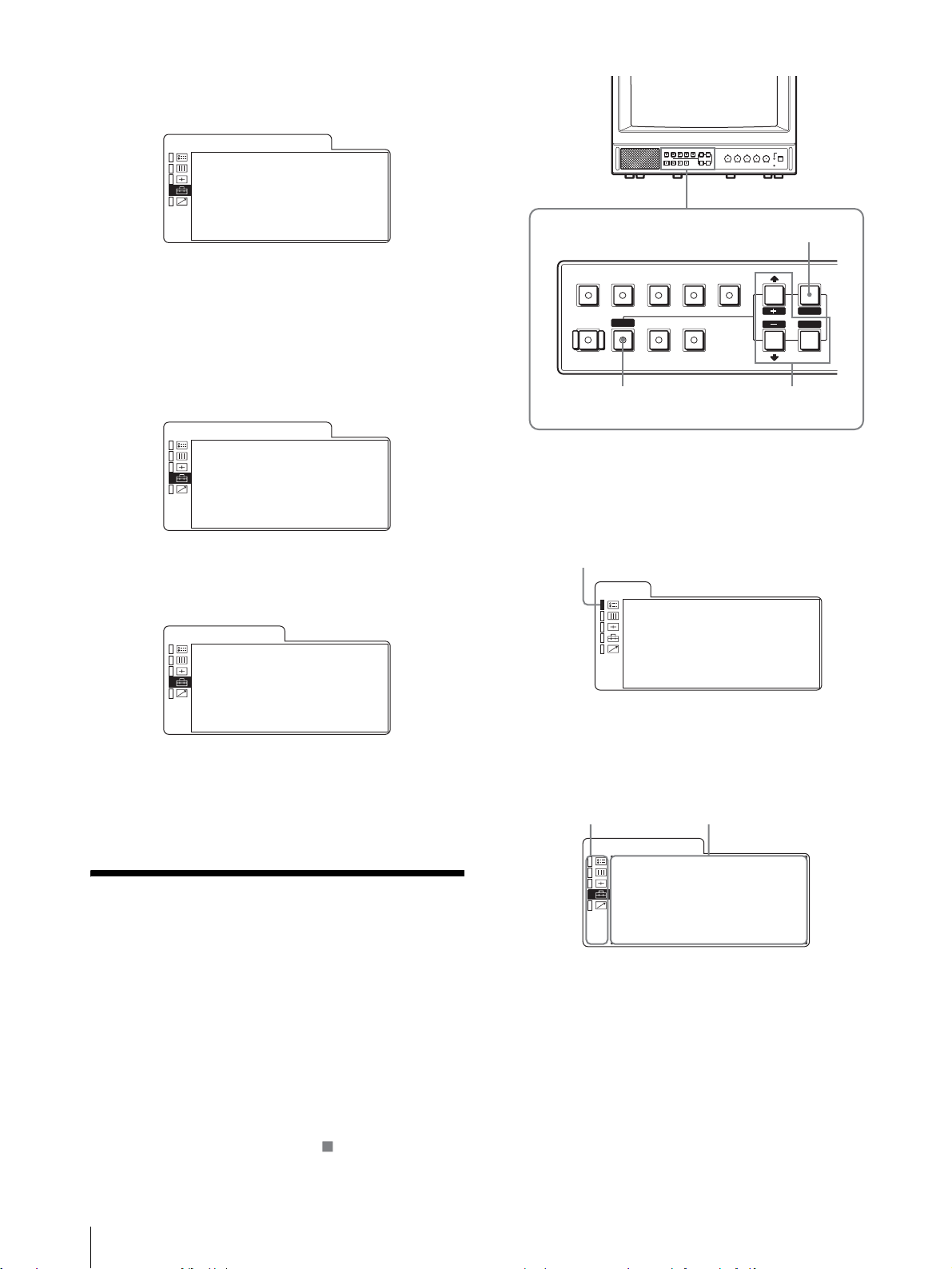
CONFIG)を選択し、ENTER/SELECT ボタンを押
す。
USERCONFIG(1/2) メニューが表示されます。
U S E R . C O N F I G ( 1 / 2 )
x
R G B S Y S T E M
•
O P T R G B S Y S T . . . x x x x x
•
N E X T P A G E
. . . . . . x x x x
1
2
m/–ボタンを押してNEXT PAGEを選んでENTER/
SELECT ボタンを押すと、USERCONFIG(2/2) が
表示されます。
3
M/+、m/– ボタンを押して「LANGUAGE」を選
び、ENTER/SELECT ボタンを押す。
選んだ項目が黄色で表示されます。
U S E R . C O N F I G ( 2 / 2 )
• P R E V I O U S P A G E
x
L A N G U A G E E N G L I S H
A U T O C H R O M A / P H A S E
•
A U T O A D J V A L U E x x
•
S T A R T
4
M/+、m/– ボタンを押して表示させたい言語を選ぶ
と、その言語の表記に切り換わります。ENTER/
SELECT ボタンで決定します。
ʰ˂ʀ˂ᜫް ¨ ² ¯² ©
ˁ±¯²ɋ
Ǫǽǽǽǽǽǽǽǽǽǽǽǽǽǽǽஓట
ɴ˂ʒɹʷʨ ¯ ʟɱ˂ʄ
ˁɴ˂ʒᝩϏǽǽǽǽǽǽǽǽǽǽǽǽǪǪ
ˁᝩʃʉ˂ʒ
メニュー画面を消すには
MENU/EXIT ボタンを押す。
約 1 分間操作をしないとメニューは自動的に消えます。
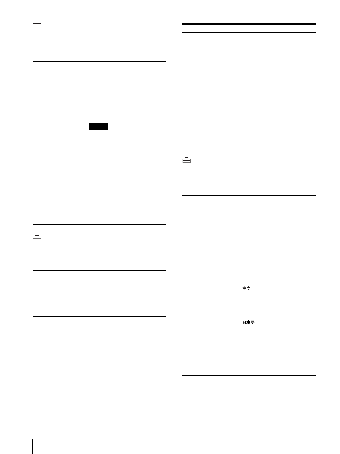
メニューの操作方法
本機では、画質調整や入力信号の設定、初期設定の変更
など、各種調整や設定をメニュー画面で行います。
調整や設定を行う場合の操作は以下のとおりです。
◆メニュー項目について詳しくは「メニューを使った調
整」(13 ページ)をご覧ください。
B
RESET
RGB/
COMPONENT
UNDER
SCAN
LINEALINE
DEGAUSS
RESET ボタン
1
MENU/EXIT ボタンを押す。
OPTION
1
OVER
SCAN
OPTION
2
ENTER
2, 3, 4
メニュー画面が表示されます。
現在選択されているメニューが黄色いカーソルで表
示されます。
カーソル
ᜫްৰ
αհʟɳ˂ʨʍʒǽǽǽǽǽǽǽǽǽǪǪǪǪ
ǽǽǽǽǽǽǽǽǽǽǽǽǽǽǽǽǪǪǪǪǪ
ᓨຣ࣊ǽǽǽǽǽǽǽǽǽǽǽǽǽǽǽǪǪǪ
ɽʽʧ˂ʗʽʒʶʣʵǽǽǽǽǽǽǪǪǪǪǪ
ÎÔÓÃʅʍʒɬʍʡǽǽǽǽǽǽǽǽǽǪǪ
ÒǯÃÏÍÐҒ૰ǽǽǽǽǽǽǽǽǪǪǪ
ɴʡʁʱʽǽǽǽǽǽǽǽǽǽǪǪǪǪǪǪǪ
2
M/+、m/– ボタンを押してメニューを選び、
ENTER/SELECT ボタンを押す。
選んだメニューのアイコンが黄色で表示され、設定
項目が表示されます。
メニュー
ʰ˂ʀ˂ᜫް ¨ ± ¯² ©
ǪÒÇÂᜫްǽǽǽǽǽǽǽǽǽǪǪǪǪǪǪ
ˁɴʡʁʱ ʽÒÇÂᜫްǽǪǪǪǪǪǪǪǪǪ
ˁ²¯²ɋ
3
M/+、m/– ボタンを押して設定項目を選び、
設定項目
ENTER/SELECT ボタンを押す。
変更する項目が黄色で表示されます。
MENU
EXIT
SELECT
メニュー画面表示の言語を切り換えることもできます。
◆表示言語を変えるには、「メニュー表示言語の切り換
え」(11 ページ)をご覧ください。
なお、メニュー画面のイラスト上の マーク部分に、本
機の現在の設定値が表示されます。
メニュー表示言語の切り換え/メニューの操作方法
12
4
設定項目の調整や設定をする。
数値を変更する項目の場合:
数値を大きくするときは、
数値を小さくするときは、
M/+ ボタンを押す。
m/– ボタンを押す。
ENTER/SELECT ボタンを押すと確定され、元の画
面に戻ります。
設定を選ぶ場合:
M/+、m/– ボタンを押して設定を選び、ENTER/
SELECT ボタンを押す。
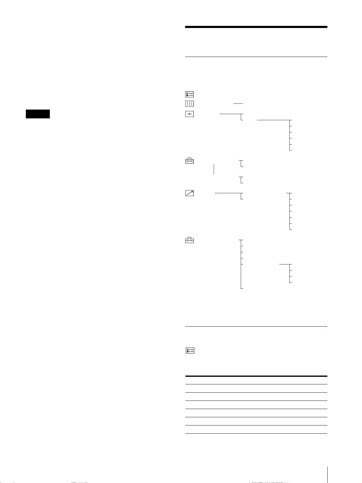
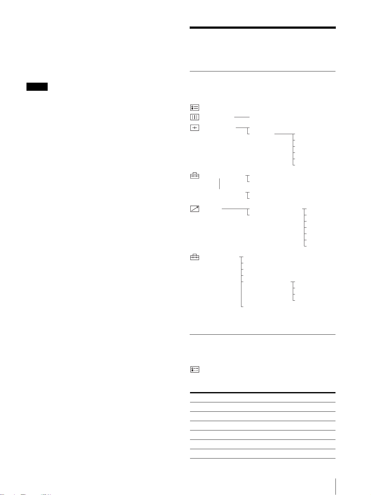
メニューを使った調整
項目一覧
本機のスクリーンメニューは次のような構成になってい
ます。
ᜫްৰ
ʥʹɮʒʚʳʽʃ
±©
ᓨຣ࣊
ご注意
設定項目で青色表示の項目はアクセスできない状態を意
味します。白色表示に変わるとアクセスが可能になりま
す。
メニュー画面を消すには
MENU/EXIT ボタンを押す。
約 1 分間操作をしないとメニューは自動的に消えます。
設定値の記憶について
設定値は自動的に本体に記憶されます。
設定値をリセットする
メニュー内の項目を調整中に RESET ボタンを押すと調整
は無効になり、調整前の値に戻ります。
ʡʴʅʍʒ
ʰ˂ʀ˂ᜫްᴥ±¯²ᴦ
ʰ˂ʀ˂ᜫްᴥ²¯²ᴦ
ʴʬ˂ʒ
ʰ˂ʀ˂ɿ˂ʝʃ
1)
設定状態メニューは表示のみ。
2)
ユーザーサービスメニューへの入りかたについて詳しくは、
15 ページをご覧ください。
ʡʴʅʍʒ
ᝩ®®®
ÒÇÂᜫް
ɴʡʁʱʽÒÇÂᜫް
ɴ˂ʒɹʷʨ¯ʟɱ˂ʄ
ʛʳʶʵʴʬ˂ʒ®®®
ʁʴɬʵʴʬ˂ʒ
²©
ʟɳ˂ʨʍʒ᚜ᇉ
ɽʽʧ˂ʗʽʒʶʣʵ
ÎÔÓÃʅʍʒɬʍʡ
ʑɶɰʃʑɭʶɮ
ʰ˂ʀ˂ᓨຣ࣊
ɿʠɽʽʒʷ˂ʵ
ɽʽʒʳʃʒ®®®
ʠʳɮʒ®®®
ɹʷʨ®®®
ʟɱ˂ʄ®®®
ɬʛ˂ʋʭ˂®®®
ʦʴʯ˂ʪ®®®
±ʞʽ
²ʞʽ
³ʞʽ
´ʞʽ
¶ʞʽ
·ʞʽ
¸ʞʽ
ʨʕʯɬʵᝩ
ɼɮʽᝩ®®®
ʚɮɬʃᝩ®®®
ൈໄϏɥɽʞ˂
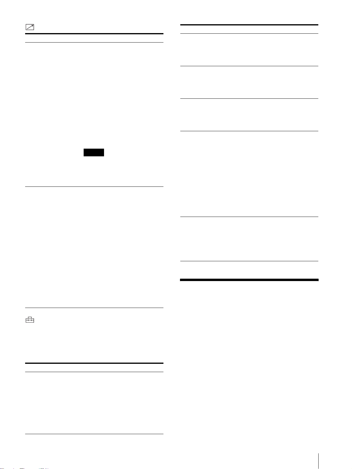
調整と設定
設定状態メニュー
本機の現在の設定状況を表示します。表示される項目は
以下のとおりです。
サブメニュー 設定
信号フォーマット 表示のみ
色温度 表示のみ
コンポーネントレベル 表示のみ
NTSCセットアップ 表示のみ
RGB/COMP 切換 表示のみ
オプション 表示のみ
メニューの操作方法/メニューを使った調整
13
ホワイトバランスメニュー
画質のホワイトバランスを調整するメニューです。ホワ
イトバランスの調整には測定器が必要です
。
ユーザー設定(1/2、2/2)メニュー
言語の選択や、RGB とコンポーネントの切り換えなどを
設定します。
サブメニュー 設定
色温度 色温度を「D65」、「D56」、「D93」、「ユー
ザー設定」から設定します。ユーザー設定
は異なる色温度に調節することができます
(色温度の調節には測定器が必要です)。
ご注意
・ ユーザー設定の色温度は、5000K 〜
10000Kの範囲で設定できます。
・ D93 は、内視鏡等の用途に適していま
す。
・ D56 は、生物顕微鏡等の用途に適してい
ます。
・ ユーザー設定の調整は、ユーザーサービ
ス設定のユーザー色温度メニューで行い
ます。
◆詳しくは、15 ページのユーザーサービス
メニューをご覧ください。
プリセットメニュー
画質を調整するメニューです。
入力信号によって調整でき ない項目 は青色で 表示され ます。
サブメニュー 設定
プリセット オンを選択すると操作パネルのすべてのつ
まみが動かなくなり(REMOTE インジ
ケーター点灯)、モニターは内部に記憶され
たプリセット(初期設定)値で働きます。
調整 ... ・「コントラスト...」:コントラストを調整
します。
・「ブライト ...」:明るさを調整します。
・「クロマ ...」:色の濃さを調整します。設
定値が大きくなると濃くなり、小さくな
ると薄くなります。
・「フェーズ ...」:色相(フェーズ)を調整
します。設定値が大きくなると緑がかり、
小さくなると紫がかります。
・「アパーチャー...」:シャープネスを調整
します。設定値が大きくなるとくっきり
します。
・「ボリューム ...」音量を調整します。
サブメニュー 設定
RGB 設定(1/2) RGB/COMPONENT入力端子からの信号
をモニターするときに、入力する信号に応
じて「RGB/ INT」、「RGB / EXT」、
「COMP / INT」または「COMP / EXT」
を選択します。
オプション RGB 設定
(1/2)
言語(2/2) メニューやメッセージの表示言語を以下の
オートクロマ/
フェーズ(2/2)
オプションスロットに入れたオプション
ボードによって表示が異なります。詳しく
はオプション設定をご覧ください。
7 言語から選択できます。
「」:中国語
「ENGLISH」:英語
「DEUTSCH」:ドイツ語
「FRANÇAIS」:フランス語
「ITALIANO」:イタリア語
「ESPAÑOL」:スペイン語
「日本語」
色の濃さ(クロマ)と色相(フェーズ)を
調整します。
・ オン:オンに設定するとクロマとフェー
ズの値が自動調整値になります。
・ オフ:オフに設定するとクロマとフェー
ズの値が工場出荷値になります。
リモートメニュー
サブメニュー 設定
パラレルリモート ... PARALLELREMOTE 端子で機能を変更し
たいピンを選択します。
1 〜 4、6 〜 8 ピンに各機能を割り付けら
れます。割り付け可能な機能は以下のとお
りです。
・ – –(機能の割り付けなし。)
・LINEA
・LINEB
・RGB/COMP
・OPTION1
・OPTION2
・タリー
・ アンダースキャン
・ オーバースキャン
・ デガウス
メニューを使った調整
14
ご注意
パラレルリモートを使用する場合は、配線
が必要です。
◆ 詳しくは 17 ページをご覧ください。
サブメニュー 設定
シリアルリモート 以下の 3 種類の中から、使用するモードを
選択します。
リモートオフ:
各種の設定を、操作パネルのボタンと調整
つまみで行うとき。
リモートコントローラーは使用できません。
リモートオン:
各種の設定をRS‑232Cでコントロールす
るとき。
メニュー操作ボタンを除いて、操作パネル
上での操作はできません。
リモート&ローカル:
操作パネルのボタン、および、RS‑232Cで
コントロールするとき。
操作パネルの調整つまみは使用できません。
ユーザーサービスメニュー
上記以外の調整・設定を行うためのユーザーサービスが
あります。
ユーザーサービスへの入り方は、MENU/EXIT ボタンを
押してメニューが表示されている状態のまま下のユー
ザーサービスメニューが表示されるまで押し続けてくだ
さい。
サブメニュー 設定
フォーマット表示 入力信号のフォーマットを画面に表示させ
るかどうかを設定します。
「オン」:常に表示
「オート」:信号入力開始後約 10 秒間だ
け表示
「オフ」:常に非表示
コンポーネントレベル以下の 3 種類の中から、入力されているコ
ンポーネント信号の種類を選択します。
「SMPTE」:100/0/100/0 のコンポーネ
ント信号のとき
「BETA7.5」:100/7.5/75/7.5 のコン
ポーネント信号のとき
「BETA0」:100/0/75/0 のコンポーネ
ント信号のとき
NTSC セットアップ NTSC 信号のセットアップのレベルを選択
します。日本では0 で、アメリカでは 7.5
で運用されています。このため輸入ソフト
には 7.5 のものがあります。
デガウスディレイ 電源を入れてから自動消磁機能が働くまで
の秒数を、0 から 99 秒の間で設定できま
す。
サブメニュー 設定
ユーザー色温度 このメニューで調整した値は、14 ページの
色温度メニューでユーザー設定を選択した
ときに働きます。
ゲイン調整:
ユーザー設定のカラーバランス(ゲイン)
を調整します。
バイアス調整:
ユーザー設定のカラーバランス(バイア
ス)を調整します。
標準値をコピー:
ユーザー設定の色温度を D65、D56、
D93 に設定します。
サブコントロール 全面パネルの CONTRAST、PHASE、
CHROMA、BRIGHT 調整つまみの調整範
囲を微調整します。これらのつまみは調整
範囲のまん中にクリックがありますので、
クリック位置での微調整に使用できます。
故障かな?と思ったら
お買い上げ店などにご相談いただく前に、次の事項をご
確認ください。
・ 画面が緑色や紫色になるt入力ボタンを押して、正し
い入力を選んでください。
・ RGB/COMPONENT 入力端子に入力している信号が
表示されない
t ユーザー設定メニューを入力中の信号
に合わせて設定してください。
保証書とアフターサービ
ス
保証書
・ この製品には保証書が添付されていますので、お買い上
げの際お受け取りください。
・ 所定事項の記載内容をお確かめのうえ、大切に保存して
ください。
アフターサービス
調子が悪いときはまずチェックを
この説明書をもう一度ご覧になってお調べください。
メニューを使った調整/故障かな?と思ったら/保証書とアフターサービス
15

それでも具合の悪いときはサービスへ
お買い上げ店、またはソニーサービス窓口にご相談くだ
さい。
保証期間中の修理は
保証書の記載内容に基づいて修理させていただきます。
詳しくは保証書をご覧ください。
保証期間経過後の修理は
修理によって機能が維持できる場合は、ご要望により有
料修理をさせていただきます。
主な仕様
一般
PVM‑14L2MD
CRT: トリニトロン(P22 蛍光体)
電源: AC100 〜 240V、50/60Hz
消費電流/電力:
最大 85W 0.9 〜 0.4A( 別売りの
BKM‑150CP 装着時)
標準 75W 0.8 〜 0.35A(オプショ
ンボードなしの場合)
最大外形寸法(幅/高さ/奥行き):
約 346 × 340 × 430mm
質量: 約 18.0kg
PVM‑20L2MD
CRT: トリニトロン(P22 蛍光体)
電源: AC100 〜 240V、50/60Hz
消費電流/電力:
最大 108W 1.1 〜 0.5A( 別売りの
BKM‑150CP 装着時)
標準 98W 1.0 〜 0.4A(オプション
ボードなしの場合)
最大外形寸法(幅/高さ/奥行き):
約 450 × 457 × 529mm
質量: 約 33.0kg
入出力
入力
LINEA 入力端子
Y/C 入力 4 ピンミニ DIN(1)
VIDEO 入力 BNC 型(1)1Vp‑p + 3dB
− 6dB負同期
AUDIO 入力 ピンジャック(1)− 5dBu47kΩ
以上
LINEB 入力端子
VIDEO 入力 BNC 型(1)1Vp‑p + 3dB
− 6dB負同期
AUDIO 入力 ピンジャック(1)− 5dBu47kΩ
以上
RGB/ コンポーネント入力端子 BNC 型(3)
RGB 入力 0.7Vp‑p + 3dB− 6dB(Sync
OnGreen0.3Vp‑p 負同期)
コンポーネント入力
0.7Vp‑p + 3dB− 6dB(75%
クロミナンス標準カラーバー信
号時)
AUDIO 入力 ピンジャック(1)− 5dBu
47kΩ 以上
外部同期入力端子
BNC 型(1)0.3 〜 8Vp‑p正負両
極性 3 値または負極性 2 値
オプション AUDIO 入力端子
ピンジャック(2)
− 5dBu47kΩ 以上
リモート入力
パラレルリモート
モジュラーコネクター 8 ピン(1)
出力
LINEA 出力端子
Y/C 出力 4 ピンミニ DIN(1)ループス
ルー、75Ω 自動終端機能付き
VIDEO 出力 BNC 型(1)ループスルー、75Ω
自動終端機能付き
AUDIO 出力 ピンジャック(1)ループスルー
LINEB 出力端子
VIDEO 出力 BNC 型(1)ループスルー、75Ω
自動終端機能付き
AUDIO 出力 ピンジャック(1)ループスルー
RGB/ コンポーネント出力端子
RGB /コンポーネント出力
BNC 型(3)ループスルー、75Ω
自動終端機能付き
AUDIO 出力 ピンジャック(1)ループスルー
外部同期出力端子
BNC 型(1)ループスルー、75Ω
自動終端機能付き
内蔵スピーカー出力
0.8W(モノラル)
保証書とアフターサービス/主な仕様
16
映像信号系
周波数特性 50Hz 〜 10MHz(0dB/ − 3dB)
アパ−チャ−補正量
1)
OFF:0dB
ON:2 〜 6dB
本機は「JISC61000‑3‑2適合品」です。
本機は業務用トリニトロンカラービデオモニターです。
本機の仕様および外観は、改良のため予告なく変更する
ことがありますが、ご了承ください。
画像系
ノーマルスキャン
CRT 有効画面の 7% オーバースキャン
アンダースキャン
CRT 有効画面の 5% アンダースキャン
オーバースキャン
CRT 有効画面の 20% オーバースキャ
ン
直線性 PVM‑14L2MD
H:4% 以下
V:4% 以下
PVM‑20L2MD
H:5% 以下
V:5% 以下
色温度 D65、D56、D93、ユーザー設定(調
整可能色温度 5000K 〜 10000K)
コンバージェンスエラー
PVM‑14L2MD
中心部:0.4mm 以下
周辺部:0.5mm 以下
PVM‑20L2MD
中心部:0.5mm 以下
周辺部:0.7mm 以下
ラスターサイズ安定度
H:1.0%
V:1.0%
解像度 ( 中心部 ) 600TV 本
動作条件
温度 0 〜 40 ℃
湿度 30 〜 85% 以下 (結露のないこと )
気圧 700 〜 1060hPa
保存・輸送条件
温度 − 10 〜 40 ℃
湿度 0 〜 90%
気圧 700 〜 1060hPa
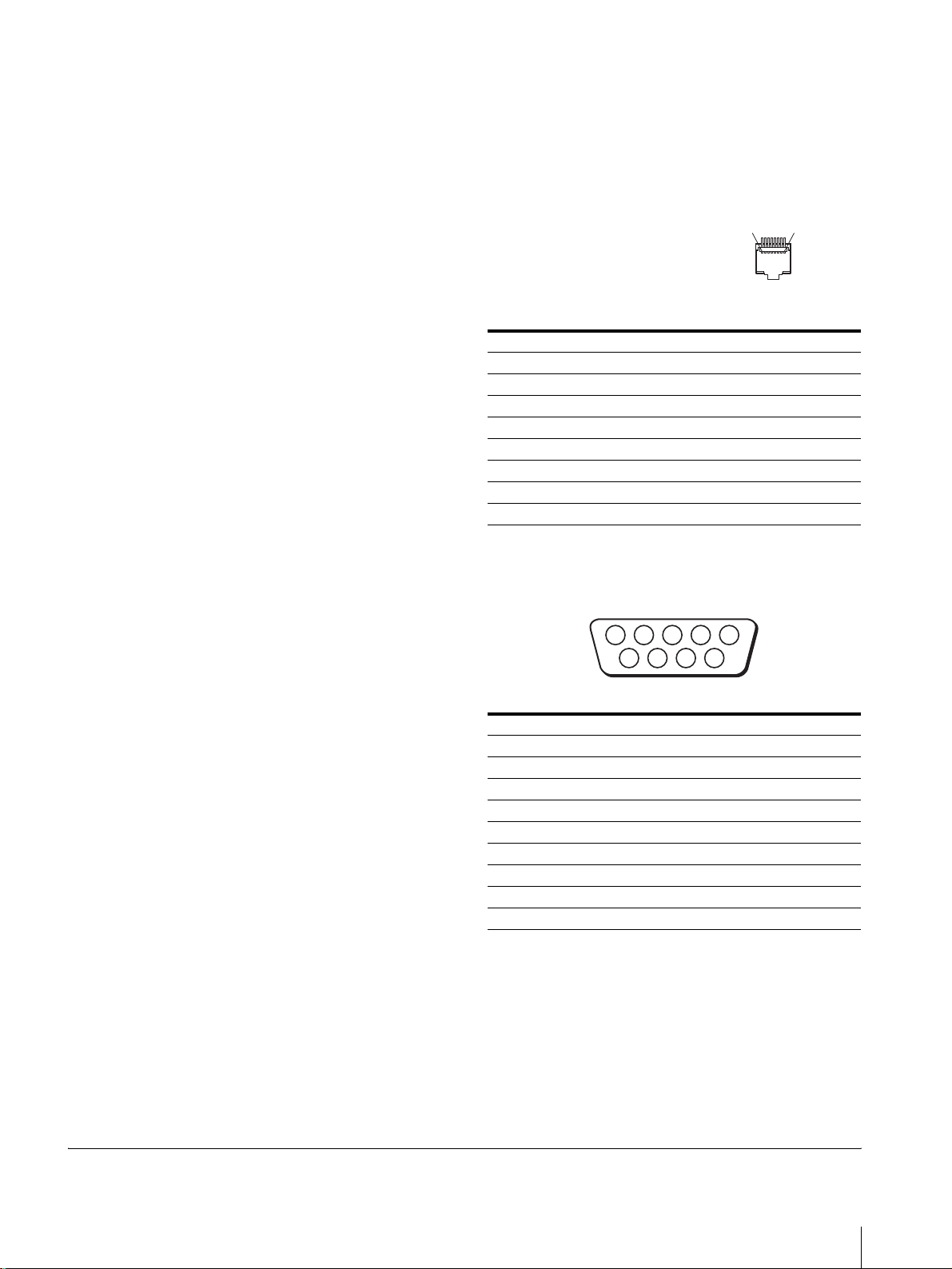
ピン配列
1
8
PARALLELREMOTE 端子
モジュラーコネクター(8 ピ
ン)
ピン番号 機能
1入力信号LINEAを指定
2 入力信号LINEBを指定
3 入力信号RGB/COMPを指定
4 入力信号オプション1 を指定
5GND
6 タリーランプのオンオフ
7 アンダースキャンの選択
8 オーバースキャンの選択
機能割り付けは、リモートメニューで変更できます。
RS‑232C 端子(DSUB9 ピン)
12345
9
ピン番号 信号
1NC
2 受信データ
3 送信データ
4NC
5GND
6NC
7送信要求
8送信可
9NC
リモートコントロールを使用するための配線
リモートコントロールで使用したい機能をアース(5 ピ
ン)に接続します。
678
付属品
AC 電源コード (1)
ACプラグホルダー (1)
取扱説明書 (1)
保証冊子 (1)
1) RGB入力時はアパーチャーの補正は行えません。
主な仕様
17

Owner’s Record
The model and serial numbers are located at the rear.
Record these numbers in the spaces provided below.
Refer to these numbers whenever you call upon your
Sony dealer regarding this product.
Model No. ____________________
Serial No. ____________________
WARNING
To prevent fire or shock hazard, do not expose
the unit to rain or moisture.
Dangerously high voltage are present inside
the unit.
Do not open the cabinet. Refer servicing to
qualified personnel only.
In the event of a malfunction or when m aintenance is
necessary, consult an authorized Sony dealer.
For the customers in the U.S.A.
This equipment has been tested and found to comply
with the limits for a Class A digital d evice, pursuant to
Part 15 of the FCC Rules. These limits are designed to
provide reasonable protection against harmful
interference when the equipment is operated in a
commercial environment.
This equipment generates, uses, and can radiate radio
frequency energy and, if not installed and used in
accordance with the instruction manual, may cause
harmful interferenc e to radio communi cations.
Operation of this equipment in a residential area is like ly
to cause harmful interference in which case the user will
be required to correct the interference at his own
expense.
Y o u are cautioned that any c hanges or modif ications n ot
expressly approved in this manual could void your
authority to operate this equipment.
For the customers in Canada
This Class A digital apparatus complies with Canadian
ICES-003.
Pour les utilisateurs au Canada
Cet appareil numérique de l a classe A est con forme à la
norme NMB-003 du Canada.
For the customers in Europe
This equipment has been found to comply with limits for
a Class B device p ursuant t o EN606 01-1-2. Ho we v er, if
this equipment does cause h armful int erference to other
devices, which can be determined by turning this
equipment off and on, the user is encouraged to try to
correct the interference by one or more of the following
measures:
• Increase the separation between the equipment and
other devices.
• Connect the equipment into an outlet on a circuit
different from that to which other devices are
connected.
• Consult the dealer or an experienced radio/TV
technician for help.
FOR CUSTOMERS IN THE UNITED KINGDOM
WARNING
THIS APPARATUS MUST BE EARTHED
IMPORTANT
The wires in this mains lead are coloured in accordanc e
with the following code:
GREEN-AND-YELLOW — EARTH
BLUE — NEUTRAL
BROWN — LIVE
As the colours of the wires in the mains lead of this
apparatus may not correspond with the coloured
markings identifying the terminals in your plug
PROCEED AS FOLLOWS:
The wire coloured GREEN AND YELLOW must be
connected to the terminal on the plug marked with the
letter E or by the safety earth symbol or coloured
GREEN or GREEN-AND-YELLOW.
The wire coloured BROWN must be connected to the
terminal marked with the le tte r L or coloured RED.
The wire coloured BLUE must be connected to the
terminal marked with the letter N or coloured BLACK.
Ensure that your equipment is connected cor rectly — If
you are in any doubt consult a qualified electrician.
A TTENTION – When the product is installed in a
rack:
a) Elevated operating ambient temperature
If installed in a closed or multi-unit rack assembl y,
the operating ambient temperature of the rack
environment may be greater than room ambient.
Therefore, consideration should be given to installing
the equipment in an environment compatible with the
manufacture’s maximum rated ambient temperature
(Tmra: 0°C to 40°C (32°F to 104°F)).
b) Reduced air flow
Installation of the equipment in a rack should be such
that the amount of air flow required for safe
operation of the equipment is not compromised.
c) Mechanical loading
Mounting of the equipment in the rack should be
such that a hazardous condition is not achieved due
to uneven mechanical loadin g.
d) Circuit overloading
Consideration should be given to the connection of
the equipment to the supply circuit and t he effect that
overloading of circuits might have on overcurrent
protection and supply wiring.
Appropriate consideration of equipment nameplate
ratings should be used when addressing thi s concern.
e) Reliable earthing
Reliable earthing of rack-mou nted equipment should
be maintained. Parti cular attention should be gi ven to
supply connections other than direct connections to
the branch circuit (e.g., use of power strips).
f) Gap keeping
Upper and lower gap of rack-mounted equipment
should be kept 44 mm (1
3
/4 inches).
18
WARNING
Important safeguards/notices for use in the
medical environments
1 All the equipments connected to this u nit shall be
certified according to Standard IEC601-1, IEC950,
IEC65 or other IEC/ISO Standards applicable to the
equipments.
2 When this unit is used together with other equipmen t
in the patient area*, the equipment shall be either
powered by an i solation transformer or connected via
an additional protective earth terminal to system
ground unless it is certified according to Standard
IEC601-1 and IEC601-1-1.
* Patient Area
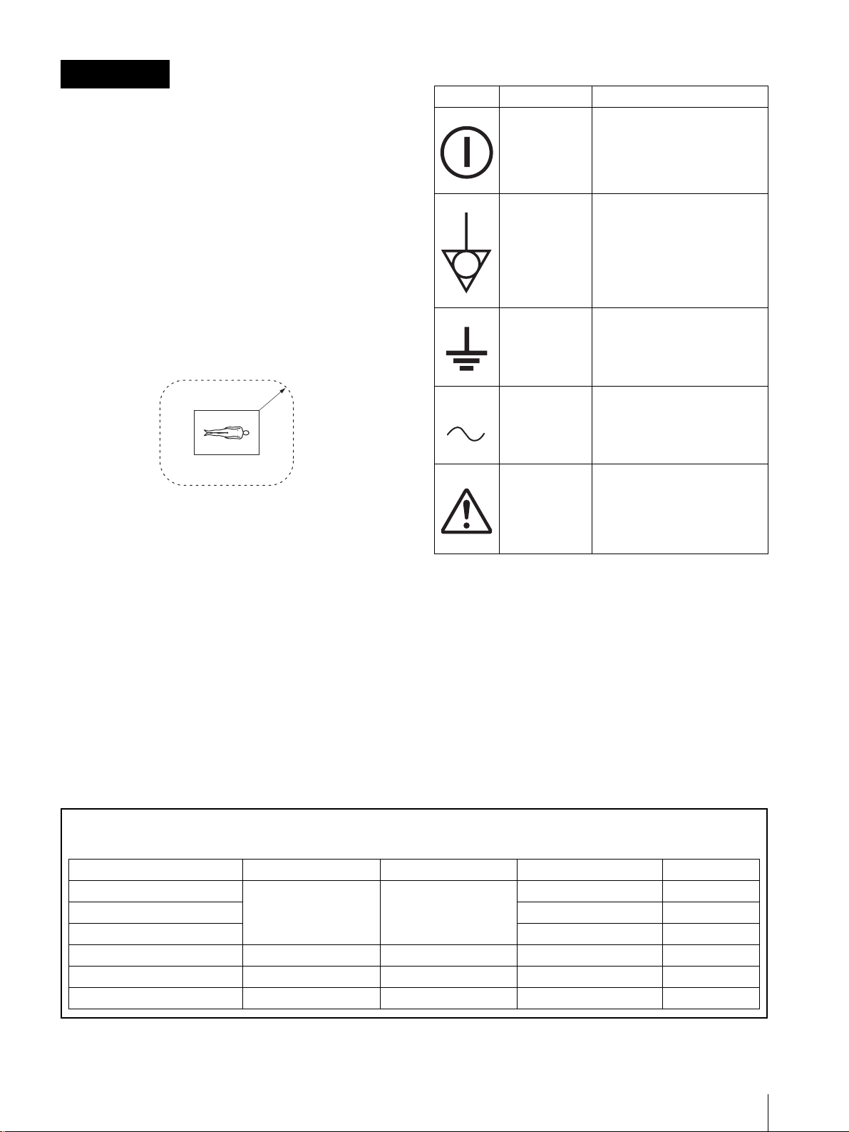
Symbols on the unit
Symbol Location This symbol indicates
Front panel Main power switch. Press to turn
the monitor on or off.
Rear panel The equipotential terminal
which brings the various parts of
a system to the same potential.
Rear panel Functional earth terminal
R1.5m
3 The leakage current could increase when connected
to other equipment.
4 The operator should take precautions to avoid
touching the rear panel i nput and output ci rcuitry and
the patient at the same tim e.
5 Model PVM-14L2MD/PVM-20L2MD is a video
monitor intended for u se in a med ical environment to
display video pictures from cameras or other video
system. These models are nonpat ient care equipment
with respect to the requirement of leakage current.
Rear panel Alternating current
Rear panel Attention, consult
ACCOMPANYING
DOCUMENTS
Warning on power connection
Use a proper power cord for your local power supply.
United State Canada Continental Europe Japan
Plug type HOSPITAL GRADE HOSPITAL GRADE LP-34A VM1050
Female end E41395 LL33182 LS-60 VM1010
Cord type E41395-A LL76662 H05VV-F PVCTF
Minimum cord set rat ing 10A/125V 10A/125V 10A/250V 12A/125V
1
Cord length Max. 4.5 m (177
Safety approval UL CSA VDE DENAN-HO
/4 in.) Max. 4.5 m (177 1/4 in.) – –
19

Table of Conten ts
Precaution ............................................................ 21
On Safety ..........................................................21
On Installation ..................................................21
On Cleaning of the CRT Surface ..................... 21
On Cleaning ..................................................... 21
On Repacking ...................................................21
On Mounting on a Rack ................................... 21
Features ................................................................ 21
Connections ..........................................................22
How to Connect the AC Power Cord ............... 22
Location and Function of Parts and Controls .. 23
Control Panel ....................................................23
Rear Panel ........................................................24
Selecting the Menu Language ............................25
Using the Menu ....................................................26
Adjustment Using the Menus .............................27
Items ................................................................. 27
Adjusting and Changing the Settings ............... 27
STATUS menu ...........................................27
COLOR TEMP menu ................................ 28
USER PRESET menu ................................ 28
USER CONFIG (1/2, 2/2) menu ................ 28
REMOTE menu ......................................... 29
USER SERVICE menu .............................. 29
Troubleshooting ................................................... 29
Specifications .......................................................30
Dimensions .....................................................i
20
The explanation giv en in this manual c an be applied t o
the following models unless noted otherwise.
When the explanation differs among models, this is
clearly indicat ed in this manual.
• PVM-14L2MD (14-inch monitor)
• PVM-20L2MD (20-inch monitor)
Unless indicated otherwise, illustrations of the video
monitor are of the PVM-14L2MD .

Precaution
On Safety
• Operate the unit only with a p ower source as specified
in the “Specifications” section.
• A nameplate indicating operating voltage, power
consumption, etc., is located on the rear panel.
• Should any solid obj ect or l iqu id fall into the cabi net ,
unplug the unit and have it checked by qualified
personnel before operating it any further.
• Do not drop or place heavy ob jects on the po wer cord.
If the power cord is damaged, turn off the power
immediately. It is dangerous to use the unit with a
damaged power cord.
• Unplug the unit from the wall outlet if it is not to be
used for several days or more.
• Disconnect the power cord from the AC outlet by
grasping the plug, not by pulling the cord.
• The socket-outlet shall be instal led near the equipment
and shall be easily accessible.
On Installation
• Allow adequate air circulati on to prev ent internal heat
build-up.
Do not place the unit on surfaces (rugs, blankets, et c.)
or near materials (curtains, draperies) that may block
the ventilation holes.
• Do not install the unit in a location near heat sources
such as radiators or air ducts, or in a place subject to
direct sunlight, excessive dust, mechanical vibration
or shock.
On Repacking
Do not throw away the carton and packing materials.
They make an ideal container which to transport the
unit. When shipping th e unit t o another lo cation, repack
it as illustrated on the carton.
On Mounting on a Rack
Leave 1U space empty above and below the monitor to
ensure adequate air circulation or install a fan to
maintain the monitor’s performance.
If you have any questions about this unit, contact your
authorized Sony dealer.
Features
Picture
Trinitron1) picture tube
Trinitron tube provides a picture whose horizontal
resolution is more than 600 TV lines at the center of the
picture.
Comb filter
When NTSC video signals are receiv ed, a comb filter is
activated to enable more accurate Y/C separation. This
contributes to less of a decrease in resolution, and less
cross color and cross luminance phenomena.
Beam current feedback circuit
The built-in beam current feedback circuit assures stable
white balance.
On Cleaning of the CRT Surface
• Clean the CRT with a soft cloth.
When the CRT is dirtied with oily hands or
fingerprints, clean it with a soft cloth moistened with
a mild detergent solution.
• Never use abrasive cleansers, alkaline soap, strong
solvents such as alcohol, thinner or benzine, since they
will damage the surface.
• Do not rub the surface of the CRT with a solid object
or hit it.
On Cleaning
T o keep the unit l ooking brand-ne w , periodically clea n it
with a mild detergent solution. Never use strong solvents
such as thinner or benzine, or abrasive cleansers since
they will damage the cabinet. As a safety prec aution,
unplug the unit before cleaning it.
1)“Trinitron” is a registered trademark of Sony Corporation.
Two color systems available
The monitor can display both NTSC and PAL signals.
The color system of th e i np ut signal is automatically
detected.
Input
Analog RGB/co m po ne nt inp ut connectors
Analog RGB or component (Y, P
video equipment can be input through th ese connectors.
Press the RGB/COMPONENT button on the control
panel to monitor the signal.
Y/C input connector (S-inp ut connector)
A video signal, split into a luminance component (Y)
and a chrominance component (C), can be input thro ugh
this connector, el iminating the interference bet ween the
two components, ensuring picture quality.
, PR) signals from
B
Precaution / Features
21
Expandable input capability
You can easily e x pand the input capability by installing
an optional board (not supplied) in th e option slot on the
rear panel. Only one board for expanding the input
capability can be installed at a time.
External sync input
Selecting the RGB/EXT item of RGB SYSTEM on the
Menu screen enables the monitor to operate on a sync
signal supplied from an external sync generator.
Fo r more details, see page see page 28.
Automatic termination (only for connectors
with a mark)
The input connector is terminated at 75 ohms int ernally
when nothing has been connected to the output
connector. If a cable is connected to the output
connector, the i nternal terminal is automatically released
and the signals inp ut to the in put connector a re output to
the output connector (loop-through).
Functions
Auto chroma phase function
The chroma and phase are automatically adjusted.
Options
EIA 19-inch rack mount bracket available
The monitor can be mounted on an EIA-standard
19-inch rack, using the following mounting brackets or
slide rails.
For the PVM- 14L2MD: MB -502B (In Europe, use the
MB-502C)
For the PVM-20L2MD: SLR-103A (In Eur ope , use th e
SLR-103C)
F or details on mounting the monitor on the rack, refer to
the user’s manual of the mounting bracket or slide rail.
Connections
How to Connect the AC P o wer Cor d
To connect the AC power cord
Plug the AC power cord into the AC IN socket. Then,
attach the AC plug holder (supplied) to the AC power
cord and slide it over the cord until it locks.
Overscan mode
The size of the image on the screen is increased by
approximately 20% to make the center of the picture
easier to see.
Underscan mode
In the underscan mod e, the lines usually sca nned outside
the normal display area are visible so that you can
monitor the entire screen area.
Note
When the monitor is in the underscan mode, dark RGB
scanning lines appear on the top edge of the screen.
These are caused by an internal test signal.
Auto/manual degaussing
The monitor is automaticall y degaussed when the po wer
is turned on. You can manually degauss the monitor by
pressing the DEGAUSS button.
Using the menu, you can preset a time to degauss
automatically after the power has been turned on for a
while.
On-screen menus
Y o u can set color temperature, perform a chroma set up,
and make other settings using the on-screen menus.
AC IN socke t
AC power cord
lock levers
AC plug holder
To remove the AC power cord
Pull out the AC plug holder while pressing the lock
levers.
22
Features / Connections
Location and Function of Parts and Controls
w
Control Panel
;
qkqjqhqg
ql
LINEALINE
DEGAUSS
B
RESET
RGB/
COMPONENT
UNDER
SCAN
OPTION
1
OVER
SCAN
OPTION
2
MENU
EXIT
SELECT
ENTER
–+
PHASECHROMABRIGHT
MAX
MIN
PUR GRN MIN MAX MIN MAX
CONTRAST
VOLUME
POWER
REMOTE
134567890qa 2qsqdqf
a POWER ! switch and lamp
Press this switch to turn on the monitor. The lamp will
light up. Press this sw itch again to turn off the monitor.
The lamp will go out.
b REMOTE indicator
This indicator lights up in the conditions below:
– When PRESET is set to ON in the menu.
– If you choose SERIAL REMOTE on the REMOTE
(RS-232C) menu of the Screen menu, and RMT ON
or RMT & LCL has been set.
c VOLUME
d CONTRAST
e PHASE
Note
control
control
control
When you use a PAL, component or RGB signal, phase
cannot be adjusted.
f CHROMA
g BRIGHT (brightness)
control
control
k OVERSCAN button and lamp
Press this button to change to the Overscan mode. The
display size is increased b y a ppr oximat el y 20% , so t hat
the center portion of the screen becomes easier to view.
To return to the original displa y size, press this button
again.
l UNDERSCAN button and lamp
Press this button for underscanning.
The display size is reduc ed by approximatel y 5% so that
the four corners of the picture are visible.
To return to the original displa y size, press this button
again.
m RESET button and lamp
You can reset the menu item setting to the previous one
by pressing RESET button while the new item is being
selected and adjusted.
n DEGAUSS button and lamp
Press this button only once. The screen will be
demagnetized. Wait for 10 minutes or more before using
this button again.
Note
h MENU/EXIT button
Press this button to show or hide on-screen menus.
i ENTER/SELECT button
Press this button to confirm an item selected on the menu.
j M/+ (move the cursor up/adjust the value)
button
m/– (move the cursor down/adjust the value)
button
Press these buttons to move the cursor or adjust an i tem
selected on the menu.
The DEGAUSS button is disabled when the screen
menu is being displayed.
To manually degauss the monitor, first, exit the screen
menu by pressing the MENU/EXIT button.
o LINE A button and lamp
Press this bu tton t o moni tor the si gnal input thr ough t he
LINE A connectors.
Location and Function of Parts and Controls
23
p LINE B button and lamp
2134567
Press this bu tton t o moni tor the si gnal input thr ough t he
LINE B connectors.
q RGB/COMPONENT button and lamp
Press this bu tton t o moni tor the si gnal input thr ough t he
RGB/COMPONENT connectors.
r OPTION 1 button and lamp
This button works when an optional board has been
installed in the option slot on the rear panel. Press this
button to moni tor the video signal input thro ugh in put 1
of the optional board and t he au dio signa l i nput through
the OPTION AUDIO INPUT 1 jack.
Rear Panel
AC IN LINE A LINE B
s OPTION 2 button and lamp
This button works when an optional board has been
installed in the option slot on the rear panel. Press this
button to mo nito r the v ideo si gnal in put thr ough input 2
of the optional boar d an d the audio signal in put thr ough
the OPTION AUDIO INPUT 2 jack.
t Tally lamp
Lights up when a video camera connected to this
monitor is selected. For the tally lamp to function
properly, certain cabling is required.
For details on this cabling, see page 31.
REMOTE
RGB/COMPONENT
G/Y
PARALLEL RS-232C
IN OUT
VIDEO
IN
AUDIO
a OPTION slot (BKM-129X)
If you install another option board, remove the BKM129X and then reinsert it.
RGB/COMPONENT IN connecto rs/EXT SYN C
(externa l synch) IN/OUT connectors
These are the input and output connectors for analog
RGB or component (Y, P
, PR) signals. Y ou can moni tor
B
them using the OPTION 1 button on the control panel.
For audio, use the OPTION A UDIO INPUT connectors.
When you use an external synchronization signal, set
RGB/EXT or COMP/EXT from RGB SYSTEM on the
USER CONFIG (1/2) menu.
You can install one optional board in this option slot. If
you install two boards, they do not function.
For details on how to install a bo ard, refer to the
installation manual supplied with the optional board.
b AC IN socket
Connect the supplied AC power cord to this socket and
then to a wall outlet.
c LINE A connectors
Line input connectors f or Y/C separate, composite vide o
and audio signals and their loop-through output
connectors.
OUT
OPTION
AUDIO INPUT
1
2
IN OUT
VIDEO
IN
OUT
AUDIO AUDIO
OUT
IN OUT
B/PB
IN OUT IN
R/P
R
IN OUT
EXT
SYNC
89
Press the LINE A butt on on the cont rol panel to monitor
the input signal through these connectors.
If you input signals to both Y/C IN and VIDEO IN, the
signal input to the Y/C IN is selected.
Y/C IN/OUT (4-pin mini-DIN)
These are the input/output connectors for a Y/C
separate signal. Connec t them to the Y/C separate
input/output connec tors on equipment such as a VCR,
video camera, or another monitor.
VIDEO IN/OUT (BNC)
These are the input/output co nnectors for a composite
video signal. Connect them to the composite video
input/output connec tors on equipment such as a VCR,
video camera, or another monitor.
AUDIO IN/OUT (phono jack)
These are the input/output jacks for an audio signal.
Connect them to the audio input/output jacks on
equipment such as a VCR.
24
Location and Function of Parts and Controls
d LINE B connectors
Line input connectors for composite video and audio
signals and their loop-through output connectors.
Press the LINE B button on th e control panel to monitor
the signal input through these connectors.
VIDEO IN/OUT (BNC)
These are the input/output connector s for a composite
video signal. Connect them to the composite video
input/output connect ors on equipment such as a VCR,
video camera, or another monitor.
AUDIO IN/OUT (phono jack)
These are the input/output jacks for an audio signal.
Connect them to the audio input/output jacks on
equipment such as a VCR.
e RGB/COMPONENT connectors
Analog RGB signal or component (Y, P
, PR) signal
B
input connectors and their loop-through output
connectors.
Press the RGB/COMPONENT button on the control
panel to monitor the signal input through these
connectors.
RS-232C (serial remote) connector (D -Sub 9
pin)
Connects to the RS-232C control connector on
external equipment connected to the monitor. The
monitor can be operated according to control
commands sent from external e quipment connected to
it.
For details, refer to the Interface Manual for
Programmers.
h Ground ( / ) terminal
Connect a GND cable.
i OPTION AUDIO INPUT 1, 2 input connectors
If an optional board h as been installe d in the optio n slot,
input an audio signal into these connectors. You can
connect up to 2 systems. To monitor the audio signals
input to OPTION A UDIO INPUT 1 or 2, press either the
OPTION 1 or OPTION 2 button.
Selecting the Menu
G/Y, B/P
, R/PR IN/OUT (BNC)
B
These are the input/output connectors for an analog
RGB and a component (Y, P
, PR) signal. Unless an
B
external sync signal is input, the monitor is
synchronized with the sync signal contained in the G/
Y signal.
AUDIO IN/OUT (phono jack)
When using an analog RGB or a componen t signal as
a video signal, use these jacks for the input/output of
an audio signal. Connect them to the audio input/
output jacks on equipment such as a VCR.
f EXT SYNC (external sync) connectors
To use an external synchronization signal, select RGB/
EXT in RGB SYSTEM on the Menu screen.
IN/OUT (BNC)
These are the input/output connectors for an external
sync signal. Input a reference signal generated by a
sync generator to the IN connector. Connect the OUT
connector to an external sync signal input connector
on equipment which you intend to synchronize with
this monitor.
Language
You can select one of seven languages (English,
German, French, Italian, Spanish, Japanese, Chinese)
for displaying the menus and other on-screen messages.
The factory preset language is ENGLISH (English).
The current settings are displayed in place of the
marks on the illustration s of the menu screen.
MENU/EXIT
button
LINEALINE
DEGAUSS
B
RESET
RGB/
COMPONENT
UNDER
SCAN
OPTION
1
OVER
SCAN
OPTION
2
MENU
EXIT
SELECT
ENTER
g REMOTE terminal
PARALLEL REMOTE (8-pin modular
connector)
Forms a switch and controls the monitor externally.
For details on the pin assignment and factory setting
function ass igned to each pin, see page 31.
ENTER/SELECT
M/+, m/– button
1
Press the MENU/EXIT but t on to display the menu
button
screen, and press the M/+ or m/– button to select
(USER CONFIG), then press the ENTER/
SELECT button.
Location and Function of Parts and Controls / Selecting the Menu Language
25
The USER CONFIG (1/2) menu appears.
U S E R . C O N F I G ( 1 / 2 )
x
R G B S Y S T E M
•
O P T R G B S Y S T . . . x x x x x
•
N E X T P A G E
2
When you press the m/–
. . . . . . x x x x
button to select NEXT
PAGE, and then the ENTER/SELECT button, the
USER CONFIG (2/2) is displayed.
3
Press the M/+ or m/– button to selec t “LANGUA GE, ”
then press the ENTER/SELECT button.
The selected item is displayed in yellow.
U S E R . C O N F I G ( 2 / 2 )
• P R E V I O U S P A G E
x
L A N G U A G E E N G L I S H
A U T O C H R O M A / P H A S E
•
A U T O A D J V A L U E x x
•
S T A R T
4
Press the M/+ or m/– button to sele ct the desired
language, the on-screen language changes to the
language you hav e selected, then press the E NTER/
SELECT button to finalize the setting.
U S E R . C O N F I G ( 2 / 2 )
• P R E V I O U S P A G E
x
L A N G U A G E E N G L I S H
A U T O C H R O M A / P H A S E
•
A U T O A D J V A L U E x x
•
S T A R T
B
RESET
RGB/
COMPONENT
UNDER
SCAN
LINEALINE
DEGAUSS
RESET button
1
Press the MENU/EXIT button.
OPTION
1
OVER
SCAN
OPTION
2
2, 3, 4
The menu appears.
The menu presently selected is indicated by a
yellow cursor.
Cursor
S T A T U S
F O R M A T
x x x x x
C O L O R T E M P
C O M P L E V E L
N T S C S E T U P . . . . . . . . . x x
R G B / C O M P S E L x x x
O P T I O N x x x x x x x
x x x x
x x x
x x x x x
1
MENU
EXIT
SELECT
ENTER
To clear the menu
Press the MENU/EXIT button.
The menu disappears automatically if a button is not
pressed within one minute.
Using the Menu
The monitor is equipped with an on-screen menu for
making various adju stments and settings such as picture
control, input setting, set setting change, etc.
Follow the instructions below to make adjustments or to
change settings.
For details on the menu items, see “Adjustment Using
the Menus” on page 27.
Y ou can al so change the menu language d isplayed in the
on-screen menu.
To change th e menu l ang ua g e, see “Selecting the Menu
Language” on page 25.
The current settings are displayed in place of the
marks on the illustration s of the menu screen.
2
Press the M/+ or m/– button to select a me nu, then
press the ENTER/SELECT button.
The menu icon presently selected is shown in
yellow and the avai lable setting items are displayed.
Menu Setting items
U S E R . C O N F I G ( 1 / 2 )
x
R G B S Y S T E M
•
O P T R G B S Y S T . . . x x x x x
•
N E X T P A G E
3
Use the M/+ or m/– button to select the desired
. . . . . . x x x x
item, then press the ENTER/SELECT button.
The item to be change d is displayed in yellow.
4
Make the setting or adjustment in an item.
When changing the adjustment level:
To increase the number, press the M/+ button.
To decrease the number, press the m/– button.
26
Selecting the Menu Language / Using the Menu
Press the ENTER/SELECT button to confirm the
number, then restore the original screen.
When changing the setting:
Press the M/+ or m/– button to change the setting.
Press the ENTER/SELECT button to confirm the
setting.
Note
An item displayed in blue cannot be accessed. You can
access the item if it is displayed in white.
To clear the menu
Press the MENU/EXIT button.
The menu disappears automatically if a button is not
pressed within one minute.
About retaining the settings
The settings are automatically stored in the monitor
memory.
Adjustment Using the
Menus
Items
The screen menu of this monitor consists of the
following items.
STATUS
COLOR TEMP
USER PRESET
USER CONFIG(1/2)
1)
COLOR TEMP
PRESET
ADJUST...
RGB SYSTEM
OPT RGB SYST
CONTRAST...
BRIGHT...
CHROMA...
PHASE...
APERTURE...
VOLUME...
To reset items being adjusted
Press the RESET button while the new menu item is
being selected and adjusted. Any changes to this new
item setting is ignored and the item is reset to the
previous setting.
USER CONFIG(2/2)
REMOTE
USER SERVICE
1) The items on the STATUS menu indicate the current settings.
2)For details on ho w to access the USER SER VICE menu, see page29.
LANGUAGE
AUTO CHROMA/PHASE
PARALLEL REMOTE...
SERIAL REMOTE
2)
FORMAT DISP
COMP LEVEL
NTSC SETUP
DEGAUSS DELAY
USER COLOR TEMP
SUB CONTROL
1 PIN
2 PIN
3 PIN
4 PIN
6 PIN
7 PIN
8 PIN
MANUAL ADJ
ADJUST GAIN...
ADJUST BIAS...
COPY FROM
Adjusting and Changing the
Settings
STATUS menu
The STATUS menu is used to display the current status
of the monitor.
Submenu Setting
FORMAT Display only
COLOR TEMP Display only
COMP LEVEL Display only
NTSC SETUP Display only
RGB/COMP SEL Display only
OPTION Display only
Using the Menu / Adjustment Using the Menus
27
COLOR TEMP menu
The COLOR TEMP menu is used for adjusting the
picture white balance.
You need to use a measurement instrument t o adj ust the
white balance.
Submenu Setting
COLOR TEMP Select the color temperature from
among D65, D56, D93 and USER
setting. Selecting a color
temperature with USER allows
adjustment of the color
temperature. (Adjustment of the
color temperature requires the us e
of measurement instrument.)
Notes
• A color temperature set with
USER can be set to any color
temperature within a range of
5000K to 10000K.
• A setting of D65 is appropriate
when using the monitor with an
endoscope.
• A setting of D56 is appropriate
when using the monitor with a
biological microscope.
• Adj us tm e nt of a se tting made
with USER can be done on the
USER COLOR TEMP menu of
the USER SER VICE men u.
For further details, see USER
SERVICE menu on page 29.
USER PRESET menu
The USER PRESET menu is used for adjusting the
picture.
Items that cannot be adjusted depending on the input
signal are displayed in blue.
Submenu Setting
PRESET When this is set to ON, all of the
controls on the control pa ne l are
disabled (the RE MOTE indicator
lights), and the preset va lu es in the
monitor’s internal memory (the
factory settings) are activated.
Submenu Setting
ADJUST... • CONTRAST...: Adjusts the
picture contrast.
• BRIGHT...: Adjusts the picture
brightness.
• CHROMA...: Adjusts the color
intensity. The higher the setting,
the greater the intensity.
The lower the setting, the lower
the intensity.
• PHASE...: Adjusts color tones.
The higher the setting, the more
greenish the picture becomes.
The lower the setting, the more
purplish the picture becomes.
• APERTURE...: Adjusts the
picture sharpness. The higher
the setting, the sharper the
picture.
• VOLUME...: Adjusts the audio
level.
USER CONFIG (1/2, 2/2) menu
The USER CONFIG menu is used to select a language for
the menus and the on-screen messages or to determine the
type of video signal acceptable on the RGB/
COMPONENT connectors.
Submenu Setting
RGB SYSTEM (1/2) When a signal input via the RGB/
COMPONENT connector is being
monitored, based on the signal
being input, select RGB/INT, RGB/
EXT, COMP/INT, or COMP/EXT.
OPT RGB SYST (1/2) The display differs dependi ng on
LANGUAGE (2/2) The languag e to be used for displa y
AUTO CHRO MA/
PHASE (2/2)
the option board installed. For
further details, refer to the option
settings.
of menu items and messages can be
selected from among the following
seven options.
[ ]: Chinese
[ENGLISH]: English
[DEUTSCH]: German
[FRANÇAIS]: French
[ITALIANO]: Italian
[ESPAÑOL]: Spanish
[ ]: Japanese
Adjusts color intensity (CHROMA)
and color tones (PHASE).
• ON: When set to ON,
CHROMA and PHASE are set
to automatic adjustment values.
• OFF: When set to OFF,
CHROMA and PHASE are set
to the factory settings.
28
Adjustmen t U s ing the Menus
REMOTE menu
Submenu Setting
PARALLEL REMOTE ... The REMOTE menu is used to
assign the functions to the pins of
the PARALLEL REMOTE
terminal.
Pin 1 to 4 and pin 6 to 8 can be
used. The following lists the
functions you can assign to the
pins.
• – – (No function is assigned.)
•LINE A
•LINE B
• RGB/COMP
•OPTION 1
•OPTION 2
•TALLY
• UNDERSCAN
• OVERSCAN
•DEGAUSS
Note
If you use the PARALLEL
REMOTE func tio n, yo u ne e d to
connect cables.
For more details, see page 31.
SERIAL REMOTE Select one out of following three
modes.
RMT OFF:
You can adjust settings and controls
by the buttons and controls on the
control panel.
The RS-232C connector does not
function.
RMT ON:
You can adjust settings and controls
through the RS-232C connector.
Buttons and controls on the control
panel, except the menu operation
ones, do not function.
RMT & LCL:
You can adjust settings and controls
both through the RS-232C
connector and the control panel
buttons.
Controls on the control panel do not
function.
USER SERVICE menu
The USER SERVICE menu is provided for any
adjustments or settings other than those listed above.
T o access the USER SER VIC E menu, press and hold the
MENU/EXIT button while the menu is displayed, until
the USER SERVICE menu shown below appears.
Submenu Setting
FORMAT DISP Determines whether the format of a
input signal is displayed on the
screen or not.
ON: The format is always
displayed.
AUTO: The format is displayed
for about 10 seconds when the
input of the signal begins.
OFF: The format is always
hidden.
Submenu Setting
COMP LEVEL Select the component level from
among three mode s .
SMPTE: 100/0/100/0 signal
BETA 7.5: 100/7.5/75/7.5 signal
BETA 0: 100/0/75/0 signal
NTSC SETUP Select the NTSC setup level from
two modes.
The 7.5 setup level is used mainly
in North America. The 0 setup level
is used mainly in Japan.
DEGAUSS DELAY Set s the delay tim e for auto
degaussing to start working aft er
the power is turned on. The delay
time can be set within 0 to 99
seconds.
USER COLOR TEMP The value of adjustment in this
menu works only when USER is
selected in the COLOR TEMP
menu.
• ADJUST GAIN...: Adjusts the
color balance (GAIN).
• ADJUST BIAS...: Adjusts the
color balance (BIAS).
• COPY FROM: If you select
D65, D56 or D93 with the
M/+ or m/– button, th e white
balance data of the selected
color temperature will be
copied to USER.
SUB CONTROL You can finely adjust the controls
on the front panel. CONTRAST,
PHASE, CHROMA and BRIGHT
controls have clicks at the center of
their adjustment range. You can
adjust the setting of the click
position with this fea ture.
Troubleshooting
This section may help you isolate the cau se of a problem
and as a result, eliminate the need to contact technical
support.
• The display is colored gre en or purpl e t Select the
correct input by pressi ng one of the buttons r el ated to
input.
• The signal input through the RGB/COMPONENT
input connectors does not ap pear on the scr een t
Set RGB SYSTEM on the USER CONFIG menu
appropriately according to type of input signal.
Adjustment Using the Menus / Troubleshooting
29

Specifications
General
PVM-14L2MD
CRT: Trinitron, P22 lumine scent mater ia l
Power: AC100 to 240 V, 50/60 Hz
Power consumption:
Maximum 85 W , 0.9 to 0.4 A (when the
BKM-150CP optional board has
been installed)
Standard: 75 W, 0.8 to 0.35 A (Wit hout
optional board)
Peak inrush current:
(1) Power ON, current probe method:
53 A (240 V)
(2) Hot switching inrush current,
measured in accordance with
European standard EN55103-1:
35 A (230 V)
Dimensions (max.):
Approx. 346 × 340 × 430 mm
5
(13
/8 × 13 1/2 × 17 inches)
(w/h/d)
Mass: Approx. 18.0 kg (39 lb 11 oz)
AUDIO input
Phono jack (1) –5 dBu 47 kΩ or higher
LINE B input connectors
VIDEO input
BNC type (1) 1 Vp-p +3 dB –6 dB
negative synchronization
AUDIO input
Phono jack (1) –5 dBu 47 kΩ or higher
RGB/Component input connectors
BNC type (3)
RGB input 0.7 Vp-p +3 dB –6 dB (Sync On Green,
0.3 Vp-p negative sync.)
Component input
0.7 Vp-p +3 dB –6 dB (75%
chrominance standard color bar
signal)
AUDIO input
Phono jack (1) –5 dBu 47 kΩ or higher
Externally synchronized input connector
BNC type (1) 0.3 to 8 Vp-p
± bipolarity te rnary or negative
polarity binary
Optional AUDIO input jacks
Phono jack (2) –5 dBu 47 kΩ or higher
Remote input terminal
Parallel remote
Modular connector 8-pin (1)
PVM-20L2MD
CRT: Trinitron, P22 lumine scent mater ia l
Power: AC100 to 240 V, 50/60 Hz
Power consumption:
Maximum 108 W, 1.1 to 0.5 A (when
the BKM-150CP opti onal board has
been installed)
Standard: 98 W, 1.0 to 0.4 A (Without
optional board)
Peak inrush current:
(1) Power ON, current probe method:
53 A (240 V)
(2) Hot switching inrush current,
measured in accordance with
European standard EN55103-1:
35 A (230 V)
Dimensions (max.):
Approx. 450 × 457 × 529 mm
3
(17
/4 × 18 × 20 7/8 inches)
(w/h/d)
Mass: Approx. 33.0 kg (72 lb 12 oz)
Input/output connectors
Input
LINE A input connectors
Y/C input 4 - pin mini-DIN (1)
VIDEO input
BNC type (1) 1 Vp-p +3 dB –6 dB
negative synchron ization
Output
LINE A output connectors
Y/C output 4-pin mini-DIN (1) Loop-through ,
with 75 Ω automatic terminal
function
VIDEO output
BNC type (1) Loop-through, with
75 Ω auto matic terminal functi on
AUDIO output
Phono jack (1) Loop-through
LINE B output connectors
VIDEO output
BNC type (1) Loop-through, with
75 Ω auto matic terminal functi on
AUDIO output
Phono jack (1) Loop-through
RGB/Component output connectors
RGB/Component output
BNC type (3) Loop-through, with
75 Ω auto matic terminal functi on
AUDIO output
Phono jack (1) Loop-through
Externally synchronized output connector
BNC type (1) Loop-through, with
75 Ω auto matic terminal functi on
Built-in speaker output
0.8 W (monaural)
30
Specifications
 Loading...