

Sony TRINITRON PVM-9L2, TRINITRON PVM-20L2, TRINITRON PVM-9L3, TRINITRON PVM-14L2 User Manual
4-092-824-07 (1)
Trinitron®
Color Video Monitor
取扱説明書 2 ページ _____________________________________
Instructions for Use page 20 _______________________________
Mode d’emploi page 34 ___________________________________
Gebrauchsanweisung seite 50 _____________________________
Manual de instrucciones página 66 __________________________
Instruzioni per l’uso pagina 82 ______________________________
______________________________________
電気製品は安全のための注意事項を守らないと、
火災や人身事故になることがあります。
この取扱説明書には、事故を防ぐための重要な注意事項と製品の取り扱いかたを示してあり
ます。この取扱説明書をよくお読みのうえ、製品を安全にお使いください。お読みになった
あとは、いつでも見られるところに必ず保管してください。
JP
GB
FR
DE
ES
IT
CS
PVM-9L3
PVM-9L2
PVM-14L2
PVM-20L2
© 2002 Sony Corporation

安全のために
ソニーのモニターは正しく使用すれば事故が起きないよ
うに、安全には充分配慮して設計されています。しかし、
内部に非常に高い電圧を使用しているので、まちがった
使いかたをすると、火災や感電などにより死亡や大けが
など人身事故につながることがあり、危険です。
事故を防ぐために次のことを必ずお守りください。
安全のための注意事項を守る
4 〜 6 ページの注意事項をよくお読みください。製品全
般の安全上の注意事項が記されています。
7 ページの「使用上のご注意」もあわせてお読みくださ
い。
定期点検をする
5 年に 1 度は、内部の点検を、お買い上げ店またはソ
ニーのサービス窓口にご依頼ください(有料)。
警告表示の意味
この取扱説明書および製品では、次のような表示
をしています。表示の内容をよく理解してから本
文をお読みください。
この表示の注意事項を守らないと、火災や感電な
どにより死亡や大けがなど人身事故につながるこ
とがあります。
この表示の注意事項を守らないと、感電やその他
の事故によりけがをしたり周辺の物品に損害を与
えたりすることがあります。
故障したら使わない
すぐに、お買い上げ店またはソニーのサービス窓口にご
連絡ください。
万一、異常が起きたら
・ 煙が出たら
・ 異常な音、においがしたら
・ 内部に水、異物が入ったら
・ モニターを落としたり、キャビネットを破損し
たときは
a 電源を切る。
b 電源コードや接続ケーブルを抜く。
c お買い上げ店またはソニーのサービス窓口に連絡す
る。
注意を促す記号
行為を禁止する記号
行為を指示する記号
2

目次
使用上のご注意(モニターの性能を保持するために) .... 7
磁気に対するご注意 ..............................................7
ブラウン管について ..............................................7
クリーニングについて...........................................7
ラックマウントについて .......................................7
特長 ................................................................................................7
接続 ................................................................................................8
電源コードの取り付けかた ...................................8
各部の名称と働き....................................................... ................9
操作パネル ............................................................9
後面パネル ......................................................... 10
メニュー表示言語の切り換え .............................................. 11
メニューの操作方法 ...............................................................12
メニューを使った調整 ........................................................... 13
項目一覧....... .............. ............... ............... .......... 13
調整と設定 ......................................................... 13
設定状態メニュー..................................... 13
ホワイトバランスメニュー ...................... 14
ユーザーコントロールメニュー ............... 14
ユーザー設定メニュー ............................. 14
リモートメニュー..................................... 15
オプション設定メニュー.......................... 15
故障かな?と思ったら ........................................................... 16
保証書とアフターサービス...................................................16
保証書 ................................................................ 16
アフターサービス............................................... 16
主な仕様.......... ...........................................................................16
寸法図 ........................................................... i
バッテリーの取り付けかた
(PVM‑9L3/PVM‑9L2 のみ)................裏表紙
JP
この取扱説明書について
本書は、以下のカラービデオモニターに共通のもので
す。
・ PVM‑9L3(9 インチモニター)
・ PVM‑9L2(9 インチモニター)
・ PVM‑14L2(14 インチモニター)
・ PVM‑20L2(20 インチモニター)
上記機種で説明が異なる場合は、別々に説明してありま
すので該当する部分をお読みください。
本書のイラストは、特に表示のない場合すべて PVM‑
14L2 を使用しています。
この装置は、クラス A 情報技術装置です。この装置を家
庭環境で使用すると電波妨害を引き起こすことがありま
す。この場合には使用者が適切な対策を講ずるよう要求
されることがあります。
3
下記の注意を守らないと、火災
や感電で大けがにつながるこ
とがあります。
キャビネットをはずさない、改造し
ない
内部には電圧の高い部分があり、キャビ
ネットや裏ぶたなどをはずしたり、改造し
たりすると、火災や感電の原因となります。
内部の調整や設定、点検、修理は、お買い
上げ店またはソニーのサービス窓口にご依
頼ください。
内部に水や異物を入れない
水や異物が入ると火災や感電の原因となり
ます。
万一、水や異物が入ったときは、すぐに電
源を切り、電源コードや接続ケーブルを抜
いて、お買い上げ店またはソニーのサービ
ス窓口にご相談ください。
規定の電源電圧で使う
取扱説明書に記されている電源電圧でお使
いください。
DC(直流)電源で動作できるモニターは、
取扱説明書に記されている電源アダプター
あるいはバッテリーパックでお使いくださ
い。
規定外の電源電圧での使用は、火災や感電
の原因となります。
油煙、湯気、湿気、ほこりの多い場
所では設置・使用しない
上記のような場所に設置すると、火災や感
電の原因となります。
この取扱説明書に記されている仕様条件以
外の環境での使用は、火災や感電の原因と
なります。
ラックマウント時は専用ブレーカー
を取り付ける
ラックマウント時は前面より電源を切るこ
とができません。設置の際は専用ブレー
カーを取り付けて使用してください。
電源コードを傷つけない
電源コードを傷つけると、火災や感電の原
因となります。
・ 設置時に、製品と壁やラック、棚などの
間に、はさみ込まない。
・ 電源コードを加工したり、傷つけたりし
ない。
・ 重いものをのせたり、引っ張ったりしな
い。
・ 熱器具に近づけたり、加熱したりしない。
・ 電源コードを抜くときは、必ずプラグを
持って抜く。
万一、電源コードが傷んだら、お買い上げ
店またはソニーのサービス窓口に交換をご
依頼ください。
ラックマウントした機器を、2 台以
上同時に引き出さない
2 台以上同時に引き出すと、機器の重みで
ラックが転倒し、けがの原因となります。
一度にラックから引き出すのは 1 台だけに
してください。
また、ラックが転倒・移動しないように適
切な処置をとってください。
4

下記の注意を守らないと、けが
をしたり周辺の物品に損害を与
えることがあります。
ぬれた手で電源プラグをさわらない
ぬれた手で電源プラグを抜き差しすると、
感電の原因となることがあります。
接続の際は電源を切る
電源コードや接続ケーブルを接続するとき
は、電源を切ってください。感電や故障の
原因となることがあります。
指定された電源コード、接続ケーブ
ルを使う
付属の、あるいは取扱説明書に記されてい
る電源コード、接続ケーブルを使わないと、
感電や故障の原因となることがあります。
他の電源コードや接続ケーブルを使用する
場合は、お買い上げ店またはソニーのサー
ビス窓口にご相談ください。
バッテリーパックは確実に取り付け
る
本機に AC/DC 電源やリチウムイオンバッ
テリーパックを取り付けるときは、この取
扱説明書の該当する箇所をよく読んだうえ
確実に取り付けてロックしたことを確認し
てください。取り付け方法を誤ると落下し
てけがをすることがあります。
通風孔をふさがない
通風孔をふさぐと内部に熱がこもり、火災
や故障の原因となることがあります。風通
しをよくするために次の項目をお守りくだ
さい。
・ 壁から 10cm 以上離して設置する。
・ 密閉された狭い場所に押し込めない。
・ 毛足の長い敷物(じゅうたんや布団など)
の上に設置しない。
・ 布などで包まない。
・ あお向けや横倒し、逆さまにしない。
水のある場所に設置しない
水が入ったり、ぬれたりすると、火災や感
電の原因となることがあります。雨天や降
雪中、海岸や水辺での使用は特にご注意く
ださい。
不安定な場所に設置しない
ぐらついた台の上や傾いたところなどに設
置すると、モニターが落ちたり、倒れたり
して、けがの原因となることがあります。
また、設置・取り付け場所の強度を充分に
お確かめください。
直射日光の当たる場所や熱器具の近
くに設置・保管しない
内部の温度が上がり、火災や故障の原因と
なることがあります。
真夏の、窓を閉め切った自動車内では 50
℃を越えることがありますので、ご注意く
ださい。
モニターは、2 人以上で開梱・運搬
する
モニターは見た目より重量があります。開
梱や運搬は、けがや事故を防ぐため、必ず
2 人以上で行ってください。1 人で行うと
腰を痛めることがあります。
転倒、移動防止の処置をする
モニターをラックに取り付け・取りはずし
をするときは、転倒・移動防止の処置をし
ないと、倒れたり、動いたりして、けがの
原因となることがあります。安定した姿勢
で注意深く作業してください。
また、ラックの設置状況、強度を充分にお
確かめください。
モニターの上に乗らない、重いもの
を載せない
倒れたり、落ちたり、壊れたりして、けが
の原因となることがあります。
お手入れの際は、電源を切って電源
プラグを抜く
電源を接続したままお手入れをすると、感
電の原因となることがあります。
5

下記の注意を守らないと、けが
をしたり周辺の物品に損害を与
えることがあります。
移動させるときは電源コード、接続
ケーブルを抜く
接続したまま移動させると、電源コードや
接続ケーブルが傷つき、火災や感電の原因
となることがあります。
定期的に内部の掃除を依頼する
長い間掃除をしないと内部にホコリがたま
り、火災や感電の原因となることがありま
す。1 年に 1 度は、内部の掃除をお買い上
げ店またはソニーのサービス窓口にご依頼
ください(有料)。
特に、湿気の多くなる梅雨の前に掃除をす
ると、より効果的です。
電源プラグは突きあたるまで差し込
む
まっすぐに突きあたるまで差し込まないと、
火災や感電の原因となります。
安全アースを接続する
安全アースを接続しないと、感電すること
があります。
次の方法でアースを接続してください。
指定の電源コードから出ている緑色のアー
ス線を建物に備えられているアース端子に
接続してください。
安全アースを取りつけることができない場
合は、ソニーのサービス担当者または営業
担当者にご相談ください。
電池についての安全上の
ご注意
ここでは、PVM‑9L3/PVM‑9L2 での使用が可能なソ
ニー製リチウム電池についての注意事項を記載していま
す。
万一、異常が起きたら
煙が出たら
a 機器の電源スイッチを切る。
b ソニーのサービス担当者に連絡する。
電池の液が目に入ったら
すぐにきれいな水で洗い、ただちに医師の治療を受ける。
電池の液が皮膚や衣服に付いたら
すぐにきれいな水で洗い流す。
バッテリー収納部内で液が漏れたら
よくふき取ってから、新しい電池を入れる。
下記の注意事項を守らないと、
破裂・発火・発熱・液漏れ
により、死亡や大けがになるこ
とがあります。
・ 火中に投入、加熱、はんだ付けをしない。
・ 分解、改造をしない。
・ 直射日光の当たるところ、炎天下の車、ストーブのそば
など高温の場所で、使用・放置・充電をしない。
・ ハンマーでたたくなどの強い衝撃を与えたり、踏みつけ
たりしない。
・ 接点部や 3 極と # 極をショートさせたり、金属製のも
のと一緒に携帯・保管をしない。
下記の注意事項を守らないと、
破裂・発火・発熱・液漏れ
により、死亡や大けがなどの人
身事故になることがあります。
・ 電池使用中や保管時に異臭がしたり、発熱・液漏れ・変
色・変形などがあったときは、すぐに使用や充電をや
め、火気から遠ざける。
6

使用上のご注意(モニターの
特長
性能を保持するために)
磁気に対するご注意
・ 磁気を発生するものを近づけないでください。画面が揺
れたり、色が乱れたりすることがあります。
・ モニターの設置の向きによっては、画面が傾いたり、色
が乱れることがありますが、故障ではありません。この
ときは、一度電源を切り、再び電源を入れてください。
自動消磁されます。または操作パネルの DEGAUSS
(消磁)ボタンを押して消磁することもできます。
◆ DEGAUSS ボタンについて詳しくは、9 ページの
qfDEGAUSS ボタンをご覧ください。
ブラウン管について
・ 柔らかいきれいな布で軽く拭いてください。手の油や指
紋などは水で薄めた中性洗剤溶液を含ませた柔らかい布
で拭いてください。
・ 表面は傷つきやすいので、硬いものでこすったり、たた
いたり、ものをぶつけたりしないでください。研磨剤を
含むもの、アルカリ系洗剤、アルコールやベンジン、シ
ンナーなどを含んだ溶剤は、表面を傷める原因になる恐
れがありますのでご使用にならないでください。
クリーニングについて
・ お手入れの際は、必ず電源を切って電源プラグを抜いて
ください。
・ キャビネットの汚れがひどいときは、水で 5 〜 6 倍に
薄めた中性洗剤液に柔らかい布をひたし、かたくしぼっ
てから汚れを拭きとります。このあと乾いた布でから拭
きしてください。
・ シンナーやベンジンなどの薬品類は、表面の仕上げを傷
めたり、表示が消えてしまうことがありますので、使用
しないでください。
ラックマウントについて
ラックマウント時は、モニターの性能維持のため上下に
1U 空けて、通気孔の確保や通気ファンの設置を行って
ください。
画像
解像度
1)
トリニトロン
600 本以上の画像が得られます。(PVM‑14L2/PVM‑
20L2 のみ)
くし形フィルター
くし形フィルターの採用により、NTSC 信号のクロスカ
ラー妨害(文字のまわりの虹)やカラーノイズ(色のに
じみ)をなくし、きめ細かで透明度の高い画像が得られ
ます。
ビームカレントフィードバック回路
長期間安定したホワイトバランスが得られます。
2 カラー方式
NTSC、PAL の 2 つのカラー方式に自動で切り換わりま
す。
管の採用により、中心部の解像度が
入力
アナログ RGB/ コンポーネント入力端子(PVM‑14L2/
PVM‑20L2 のみ)
ビデオ機器のアナログ RGB、コンポーネント信号を入力
できます。操作パネルの RGB/COMPONENT ボタンを
押してモニターします。
Y/C 入力端子(S 入力端子)
ビデオ機器などの映像信号を、輝度信号(Y)と色信号
(C)の 2 つに分離したまま入力できます。これにより、
色のにじみやちらつきの少ない、鮮明な画像が得られま
す。
拡張可能な入力機能
本機後面のオプションスロットに別売りの入力拡張用オ
プションボードを装着することで、入力系統を容易に拡
張できます。入力拡張用オプションボードは 1 枚のみ装
着できます。2 枚装着すると、機能しません。
外部同期信号入力端子
外部同期信号発生器などからの同期信号を入力できます。
操作パネルの EXTSYNC ボタンを押すと、外部同期で動
作します。
1)トリニトロンはソニー株式会社の登録商標です。
使用上のご注意(モニターの性能を保持するために)/特長
7
自動終端解放( マーク付きの端子)
後面の入力端子は、出力端子に何も接続していないとき
は、内部的に 75Ω で終端されています。出力端子にケー
ブルが接続されると、内部の終端が自動的に解放され、
入力端子に入力された信号が出力端子に出力されます
(ループスルー)。
機能
オートクロマ・フェーズ機能を標準装備
色の濃さ(クロマ)や色相(フェーズ)を自動調整する
機能を標準装備しています。
◆マウント方法についてはマウンティングブラケットま
たはスライドレールの取扱説明書をご覧ください。
キャプションビジョン(クローズド・キャプション)デ
コーダー対応可能
部品を 1 点追加することによりクローズドキャプション
に対応します。キャプションのオン / オフとその種類の選
択は、メニューで行います。
追加部品について詳しくは、お買い上げ店にお問い合わ
せください。
ブルーオンリーモード
ブルーオンリーモードにすると、入力信号の青色成分が
表示されます。色の濃さ(クロマ)や色相(フェーズ)
の調整、VTR ノイズの監視に便利です。
アンダースキャンモード
通常、画面外に走査されている信号まで画面に表示し、
画像全体をモニターすることができます。
ご注意
アンダースキャン時に、画面上端に赤青緑の走査線が見
えますが、これは本体内部の動作によるものです。
16:9 表示モード
横縦比 4:3 の信号だけでなく、横縦比 16:9 の入力信
号を正しくモニターすることができます。
自動 / 手動消磁機能
ブラウン管は、電源投入時に自動的に消磁されます。ま
た、DEGAUSS ボタンを押すと手動で消磁できます。
電源投入後から、自動的に消磁されるまでの時間をメ
ニューで設定することもできます。
スクリーンメニュー機能
画面にメニューを出して、接続するシステムに最適なモ
ニターの設定や調整をすることができます。
オプション
接続
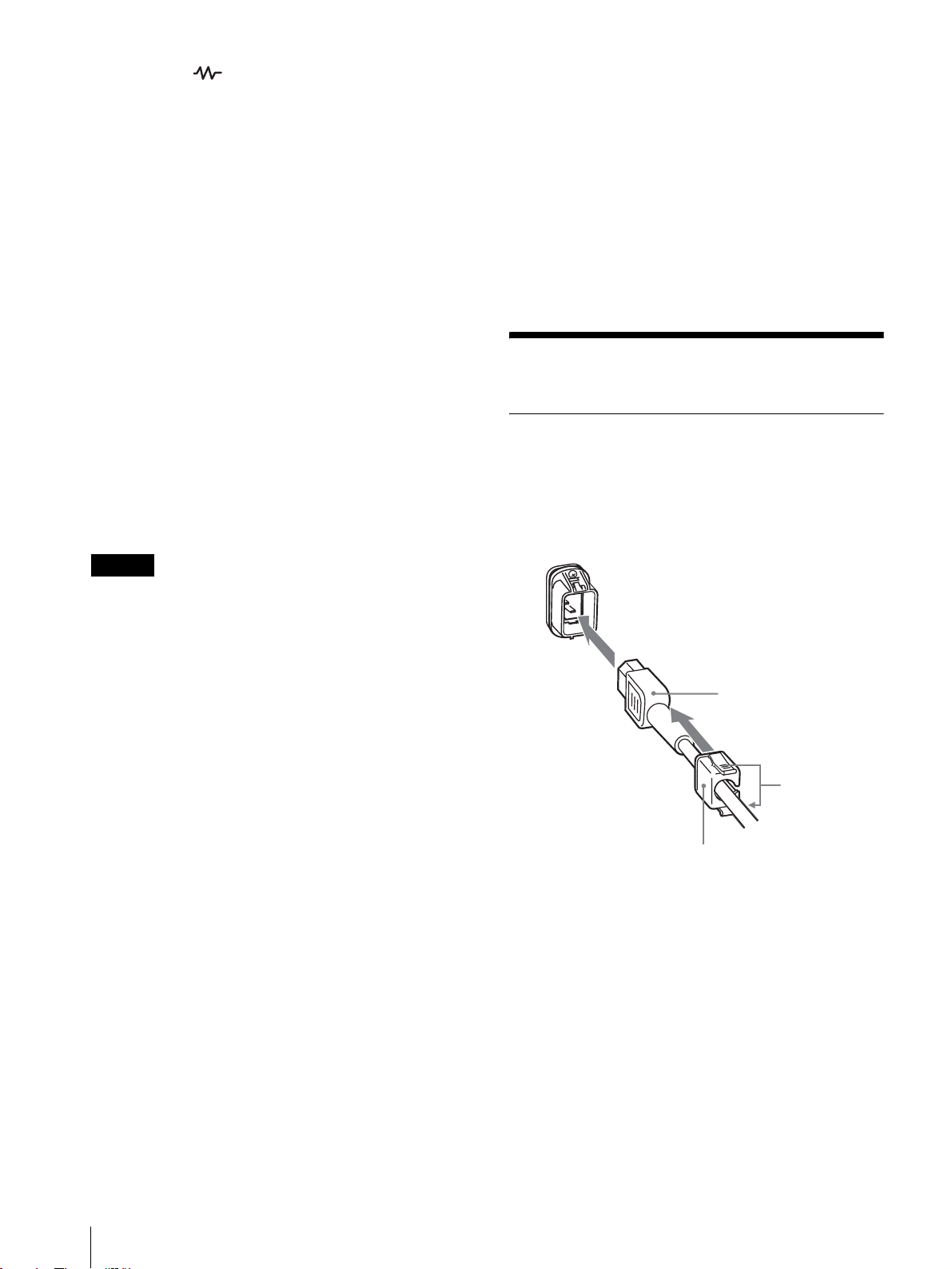
電源コードの取り付けかた
電源コードをつなぐには
AC 電源コードを後面の ACIN ソケットに差し込み、AC
電源プラグホルダーを AC 電源コードに取り付け、固定
レバーがロックするまではめ込みます。
ACIN ソケット
AC 電源コード
固定レバー
AC 電源プラグ
ホルダー
電源コードをはずすには
AC 電源プラグホルダーの固定レバーを両側からはさんで
ロックをはずし、引き抜きます。
EIA 規格の 19 インチラックに収納可能
別売りのマウンティングブラケット MB‑520(PVM‑
9L3/PVM‑9L2 用)/MB‑502B(PVM‑14L2 用)また
はスライドレール SLR‑103A(PVM‑20L2 用)を使用
すると、EIA19 インチラックにマウントすることができ
ます。
接続
8
PVM‑9L3/PVM‑9L2 は、ソニーリチウムイオンバッテ
リー(BP‑L60A/BP‑L90A)およびニッケル水素バッテ
リー(BP‑M50/BP‑M100)も使用できます。
◆バッテリーの取り付けかたについては、「バッテリーの
取り付けかた」(裏表紙)をご覧ください。

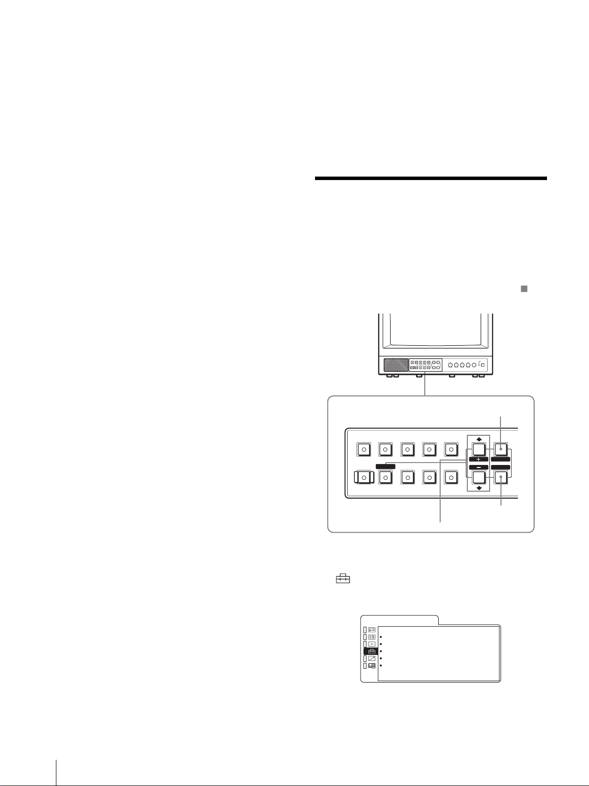
各部の名称と働き
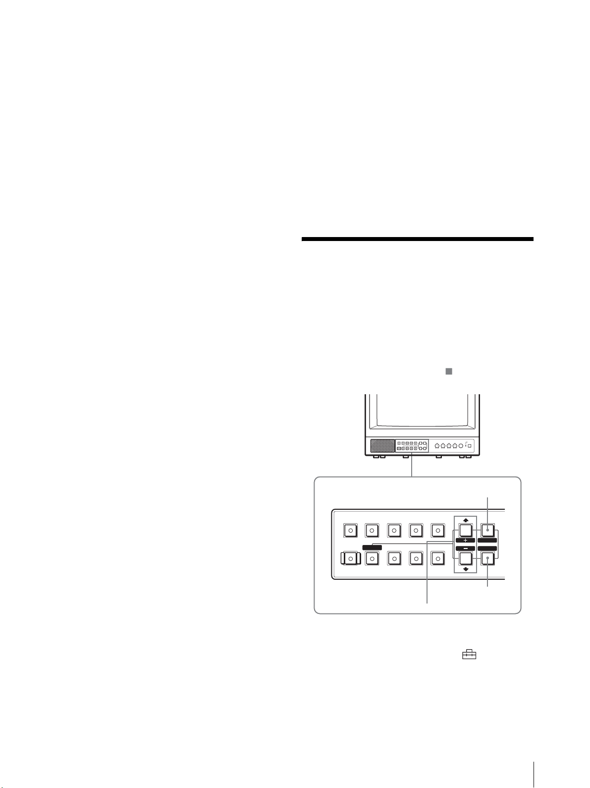
操作パネル
w;
LINEALINE
DEGAUSS
RESET
BLUE
ONLY
B
RGB/
COMPONENT
UNDER
SCAN
qkqjqhqg
OPTION
A
16 : 9
ql
OPTION
B
EXT
SYNC
MENU
EXIT
SELECT
ENTER
–+
PHASECHROMABRIGHT
MAX
MIN
PUR GRN MIN MAX MIN MAX
CONTRAST
VOLUME
POWER
q;qsqdqf
a POWER!(電源)スイッチ
押し込むと電源が入り、インジケーターが点灯します。
もう一度押すと、電源が切れます。
b VOLUME(音量)調整つまみ
c CONTRAST 調整つまみ
d PHASE(色相)調整つまみ
ご注意
PAL およびコンポーネント信号では、色相(フェーズ)
の調整はできません。
e CHROMA(色の濃さ)調整つまみ
f BRIGHT(明るさ)調整つまみ
g MENU/EXIT ボタン
メニューを出したり消したりするときに使います。
h ENTER/SELECT ボタン
メニューで内容を決定するときに使います。
i M/+(カーソル上方向移動 / 調整)ボタン
m/–(カーソル下方向移動 / 調整)ボタン
メニューでカーソルを動かしたり、数値を調整したりす
るときに使います。
j EXTSYNC(外部同期)ボタンとインジケーター
同期信号を選びます。
EXTSYNC 入力端子から入力された外部同期信号で同期
をとるときは、このボタンを押します。
123456789qa
k 16:9 ボタンとインジケーター
横縦比 16:9 の信号をモニターするときに押します。
l UNDERSCAN ボタンとインジケーター
押すとアンダースキャンモードになります。
画面サイズが約 5% 縮小され、画像の四隅まで表示され
ます。
m BLUEONLY ボタン(RESET ボタン)とインジケー
ター
・ 赤と緑の信号がカットされ、青信号のみが表示されま
す。
色の濃さ(クロマ)や色相(フェーズ)の調整、VTR
ノイズの監視が容易に行えます。(色相(フェーズ)の
調整ができるのは NTSC の映像信号だけです。)
・ メニュー項目を調整中に押すと、調整が無効になり、調
整前の設定値に戻ります。
n DEGAUSS(消磁)ボタンとインジケーター
消磁したいとき、このボタンを 1 回押します。もう一度
使用するときは 10 分以上間隔をおいてください。
ご注意
スクリーンメニューが表示されている状態では、
DEGAUSS ボタンは効きません。
手動で消磁を行う場合は、MENU/EXIT ボタンでスク
リーンメニューを消してから行ってください。
o LINEA ボタンとインジケーター
LINEA 入力端子からの信号をモニターするときに押しま
す。
各部の名称と働き
9
p LINEB ボタンとインジケーター
LINEB 入力端子からの信号をモニターするときに押しま
す。
q RGB/COMPONENT ボタンとインジケーター
(PVM‑14L2/PVM‑20L2のみ )
RGB/COMPONENT 入力端子からの信号をモニターす
るときに押します。
s OPTIONB ボタンとインジケーター
モニター後面のオプションスロットにオプションボード
が装着されているときに使用します。
オプションボードの入力 2 からの映像信号と OPTION
AUDIOINPUT2 からの音声信号をモニターするときに
押します。
(このボタンは BKM‑129X、BKM‑155DV 使用時は動作
しません。)
r OPTIONA ボタンとインジケーター
モニター後面のオプションスロットにオプションボード
が装着されているときに使用します。
オプションボードの入力1からの映像信号と OPTION
AUDIOINPUT1 からの音声信号をモニターするときに
押します。
t タリーランプ
本機に接続されているカメラの映像が選ばれると、ラン
プが点灯します。
◆タリーランプが点灯するようにするには、タリー制御
の配線が必要です。詳しくは 18 ページをご覧くださ
い。
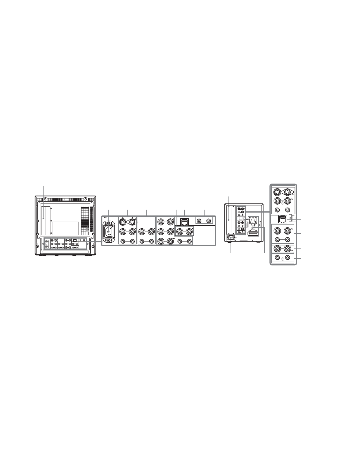
後面パネル
PVM‑14L2/PVM‑20L2 PVM‑9L3/PVM‑9L2
1
2
345678
AC IN LINE A LINE B
IN OUT
VIDEO
OUT
IN
AUDIO
RGB/COMPONENT
G/Y
IN OUT
IN
IN OUT
OUT
B/PB
IN OUT IN
R/P
R
VIDEO
AUDIO AUDIO
PARALLEL REMOTE
IN OUT
EXT
SYNC
OUT
OPTION AUDIO INPUT
1 2
1
129X
2
LINE A
IN OUT
IN OUTVIDEO
IN
OUT
AUDIO
PARALLEL
REMOTE
LINE B
IN OUTVIDEO
IN OUT
AUDIO
EXT SYNC
IN OUT
12
OPTION AUDIO INPUT
AC IN
–+
DC
12V IN
9q;
LINE A
IN OUT
IN OUTVIDEO
IN
PARALLEL
REMOTE
LINE B
IN OUTVIDEO
IN OUT
AUDIO
EXT SYNC
IN OUT
12
OPTION AUDIO INPUT
3
OUTAUDIO
7
4
6
8
a オプションスロット
オプションボードを装着するときに使用するスロットで
す。
◆入力拡張用オプションボードは 1 枚のみ装着できます。
2 枚装着すると、機能しません。装着方法について詳し
くは、オプションボードに付属の取扱説明書をご覧くだ
さい。
b ACIN ソケット
付属の AC 電源コードをつなぎます。
c LINEA 入出力端子
Y/C 分離入力、コンポジットビデオ信号と音声信号のラ
イン入力端子、およびそれぞれのループスルー端子です。
操作パネルの LINEA ボタンを押してモニターします。
Y/C 入力と VIDEO 入力を同時に接続した場合、Y/C 入
力が優先となります。
Y/CIN/OUT(4 ピンミニ DIN)
Y/C 分離の入出力端子です。VTR やビデオカメラ、他
のモニターなど、外部機器の Y/C 分離出力および入力
端子と接続します。
VIDEOIN/OUT(BNC 型)
コンポジットビデオの入出力端子です。VTR やビデオ
カメラ、他のモニターなど、外部機器のコンポジット映
像出力および入力端子と接続します。
AUDIOIN/OUT(ピンジャック)
音声の入出力端子です。VTR などの外部機器の音声出
力および入力端子と接続します。
d LINEB 入出力端子
コンポジットビデオ信号と音声信号のライン入力端子、
およびそれぞれのループスルー端子です。
操作パネルの LINEB ボタンを押してモニターします。
10
各部の名称と働き
VIDEO IN/OUT(BNC 型)
コンポジットビデオの入出力端子です。VTR やビデオ
カメラ、他のモニターなど、外部機器のコンポジット映
像出力および入力端子と接続します。
AUDIO IN/OUT(ピンジャック)
音声の入出力端子です。VTR などの外部機器の音声出
力および入力端子と接続します。
e RGB/COMPONENT 入出力端子(PVM-14L2/
PVM-20L2 のみ)
アナログ RGB またはコンポーネント(Y、PB、PR)信号
の入力端子、およびそれぞれのループスルー出力端子で
す。
操作パネルの RGB/COMPONENT ボタンを押してモニ
ターします。
i DC 12V IN 端子(XLR 型)(PVM-9L3/PVM-9L2
のみ)
外部電源 DC 12V を接続することにより、本機を動作さ
せることができます。
接続する外部電源は、クラス 2 対応 DC12V 4.2A 仕様
のものをご使用ください。
j バッテリー取り付け部(PVM-9L3/PVM-9L2 の
み)
バッテリーを取り付けます。
PVM-9L3/PVM-9L2 は、リチウムイオンバッテリー
(BP-L60A/BP-L90A)およびニッケル水素バッテリー
(BP-M50/BP-M100)に対応しています。
G/Y、B/P
アナログ RGB およびコンポーネント(Y、P
、R/PR IN/OUT(BNC 型)
B
B、PR
)の
入出力端子です。入力時は、通常 G/Y 信号に含まれて
いる同期信号で動作します。
AUDIO IN/OUT(ピンジャック)
映像信号としてアナログ RGB またはコンポーネントを
入力する場合に、音声信号の入出力端子として使用しま
す。VTR など、外部機器の音声出力および入力端子と
接続します。
f EXT SYNC(外部同期)入出力端子
外部同期信号を使う場合は操作パネルの EXT SYNC ボタ
ンを押します。
IN/OUT(BNC 型)
外部同期信号の入出力端子です。IN 端子には外部同期
信号発生器などからの基準信号を入力します。OUT 端
子は、本機と同期して動作させる他のビデオ機器の外部
同期入力端子と接続します。
g PARALLEL REMOTE(パラレルリモート)端子
(モジュラーコネクター)
パラレルコントロールスイッチを構成してモニターを外
部操作します。
◆ピン配置と出荷時の各ピンへの機能の割り付けについ
て詳しくは、18 ページをご覧ください。
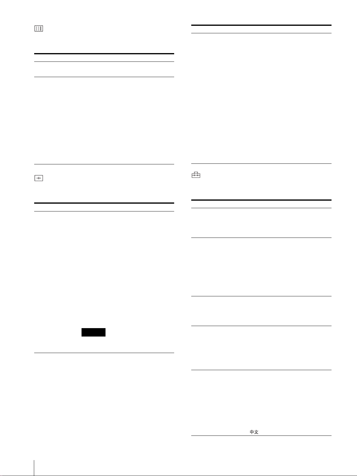
メニュー表示言語の切り
換え
メニュー画面やメッセージの表示言語を 7 言語
(ENGLISH、DEUTSCH、FRANÇAIS、ITALIANO、
ESPAÑOL、日本語、中文)の中から選ぶことができます。
出荷時の設定は「ENGLISH」(英語)に設定されていま
す。
なお、メニュー画面のイラスト上の マーク部分に、本
機の現在の設定値が表示されます。
MENU/EXIT ボタン
B
RESET
BLUE
ONLY
RGB/
COMPONENT
UNDER
SCAN
LINEALINE
DEGAUSS EXT
M/+、m/– ボタン
OPTION
OPTION
B
A
16 : 9
SYNC
ENTER/SELECT ボタン
MENU
EXIT
SELECT
ENTER
h OPTION AUDIO(オプションオーディオ) INPUT
1、2 入力端子
オプションスロットにオプションボードが装着されてい
る場合、その音声入力に使用する入力端子です。2 系統ま
で接続することができます。OPTION AUDIO INPUT 1
または 2 入力端子から入力した音声信号をモニターする
場合には、それぞれ OPTION A または OPTION B ボタ
ンを押します。
1
MENU/EXIT ボタンを押し、メニュー画面が表示さ
M/+、m/– ボタンを押して (USER
れたら
CONFIG)を選択し、ENTER/SELECT ボタンを押
メニュー表示言語の切り換え
11

す。
USERCONFIG メニューが表示されます。
U S E R C O N F I G
x R G B / C O M P S E L x x x x
C O M P L E V E L x x x x x
N T S C S E T U P x
F O R M A T D I S P x x x x
L A N G U A G E E N G L I S H
D E G A U S S D E L A Y x
2
M/+、m/– ボタンを押して「LANGUAGE」を選
び、ENTER/SELECT ボタンを押す。
選んだ項目が黄色で表示されます。
U S E R C O N F I G
R G B / C O M P S E L x x x x
C O M P L E V E L x x x x x
N T S C S E T U P x
F O R M A T D I S P x x x x
x L A N G U A G E E N G L I S H
D E G A U S S D E L A Y x
3
M/+、m/– ボタンを押して表示させたい言語を選び、
ENTER/SELECT ボタンを押す。
画面表示が、選んだ言語に切り換わります。
ɦĘȶĘપ
ĂPE@-AMKNҙýýx x x x x x x
ĂȳɳɝĘɍɳɈɬəɫýýýýxxxxx
Ă LR QAȻɃɈȢɃɗээээээээx
ĂɕȩĘɞɃɈݸээээээээx x x
ŝؘلээээээээээээээമل
ĂɇȬȦȹɇȣɬȤээээээээээx
B
RESET
BLUE
ONLY
RGB/
COMPONENT
UNDER
SCAN
LINEALINE
DEGAUSS EXT
RESET ボタン
1
MENU/EXIT ボタンを押す。
OPTION
A
16 : 9
OPTION
B
SYNC
2, 3, 4
メニュー画面が表示されます。
現在選択されているメニューが黄色いボタンで表示
されます。
પࢁ
࢘ڜɕȩĘɞɃɈýýýxxxxxxxxx
ээээээээээээxxxxxxxx
ϝээээээээээээээ xxx
ȳɳɝĘɍɳɈɬəɫэээээxxxxx
LRQ AȻɃɈȢɃɗэээээээээx
PE@ - AMKNҙýýýx x x x x x x
Ȫɗȷɧɳ
1
MENU
EXIT
SELECT
ENTER
メニュー画面を消すには
MENU/EXIT ボタンを押す。
約 1 分間操作をしないとメニューは自動的に消えます。
メニューの操作方法
本機では、画質調整や入力信号の設定、初期設定の変更
など、各種調整や設定をメニュー画面で行います。
調整や設定を行う場合の操作は以下のとおりです。
◆メニュー項目について詳しくは「メニューを使った調
整」(13 ページ)をご覧ください。
メニュー画面表示の言語を切り換えることもできます。
◆表示言語を変えるには、「メニュー表示言語の切り換
え」(11 ページ)をご覧ください。
なお、メニュー画面のイラスト上の マーク部分に、本
機の現在の設定値が表示されます。
2
M/+、m/– ボタンを押してメニューを選び、
ENTER/SELECT ボタンを押す。
選んだメニューのアイコンが黄色で表示され、設定
項目が表示されます。
メニュー
ɦĘȶĘપ
ŝ P E@ - AMKN ҙýý x x x x x x x
ĂȳɳɝĘɍɳɈɬəɫýýýýxxxxx
Ă LR QAȻɃɈȢɃɗээээээээx
ĂɕȩĘɞɃɈݸээээээээx x x
Ăؘلээээээээээээээമل
ĂɇȬȦȹɇȣɬȤээээээээээx
3
M/+、m/– ボタンを押して設定項目を選び、
設定項目
ENTER/SELECT ボタンを押す。
変更する項目が黄色で表示されます。
ご注意
項目が複数メニューページに及ぶ場合、
ボタンを押して必要なメニューページに入ります。
M/+、m/–
メニューの操作方法
12
4
設定項目の調整や設定をする。
数値を変更する項目の場合:
数値を大きくするときは、
数値を小さくするときは、
M/+ ボタンを押す。
m/– ボタンを押す。
ENTER/SELECT ボタンを押すと確定され、元の画
面に戻ります。
設定を選ぶ場合:
M/+、m/– ボタンを押して設定を選び、ENTER/
SELECT ボタンを押す。
ご注意
設定項目で青色表示の項目はアクセスできない状態を意
味します。白色表示に変わるとアクセスが可能になりま
す。
メニュー画面を消すには
MENU/EXIT ボタンを押す。
約 1 分間操作をしないとメニューは自動的に消えます。
設定値の記憶について
設定値は自動的に本体に記憶されます。
設定値をリセットする
メニュー内の項目を調整中に RESET ボタンを押すと調整
は無効になり、調整前の値に戻ります。
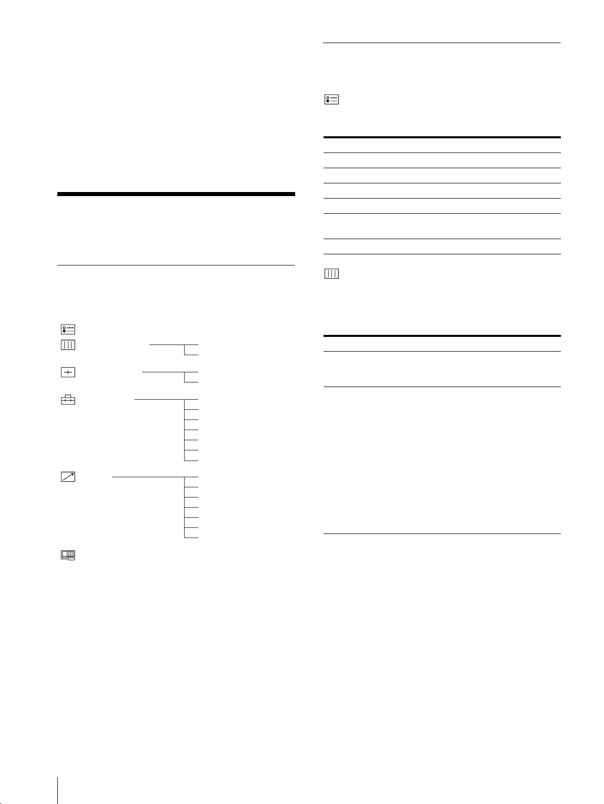
メニューを使った調整
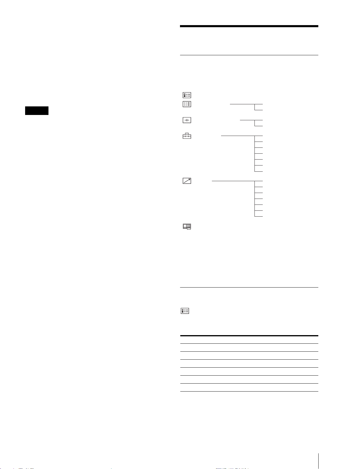
項目一覧
本機のスクリーンメニューは次のような構成になってい
ます。
પࢁ
ɛɯȤɈɐɩɳȹ
ɦĘȶĘȳɳɈɭĘɫ
ɦĘȶĘપ
ɪɢĘɈ
Ȫɗȷɧɳપ
1)
設定状態メニューは表示のみ。
2)
PVM‑14L2/PVM‑20L2 のみ。
3)
キャプションビジョン(クローズド・キャプション)デコー
ダー装着時のみ。
4)
オプション設定メニューは本機に装着するオプションボードに
よって表示される項目が異なります。
/'
2'
ϝ
ɞɋɥȢɫࣸ
ȪĘɈȯɭɞ-ɕȧĘȺ
ȵɖȳɳɈɭĘɫ
PE@-AMKNҙ
ȳɳɝĘɍɳɈɬəɫ
LRQAȻɃɈȢɃɗ
ɕȩĘɞɃɈݸ
ؘل
ɇȬȦȹɇȣɬȤ
ȭɣɗȷɧɳɓȸɧɳ
/ɔɳ
0ɔɳ
1ɔɳ
2ɔɳ
4ɔɳ
5ɔɳ
6ɔɳ
0'
1'
調整と設定
設定状態メニュー
本機の現在の設定状況を表示します。表示される項目は
以下のとおりです。
サブメニュー 設定
信号フォーマット 表示のみ
色温度 表示のみ
コンポーネントレベル 表示のみ
NTSCセットアップ 表示のみ
RGB/COMP 切換 表示のみ(PVM‑14L2/PVM‑20L2 のみ)
オプション 表示のみ
メニューを使った調整
13
ホワイトバランスメニュー
画質のホワイトバランスを調整するメニューです。ホワ
イトバランスの調整には測定器が必要です
サブメニュー 設定
色温度 色温度を「D65」、「D93」、「ユーザー設定」
から設定します。
マニュアル調整 色温度を「ユーザー設定」にしたとき、表
示が青色から白色にかわり、調整できるよ
うになります。
・ ゲイン調整...:カラーバランス(ゲイン)
を調整します。
・ バイアス調整...:カラーバランス(バイ
アス)を調整します。
・ 標準値をコピー:
押して D65 または D93 を選択する
と、選択された色温度のホワイトバ
ランスデータが、「ユーザー設定」に
コピーされます。
。
M/+、 m/– ボタンを
サブメニュー 設定
サブコントロール 操作パネルの CONTRAST、PHASE、
CHROMA、BRIGHT 調整つまみの調整範
囲を微調整します。
・ 調整 ...:選択すると以下の項目が調整で
きます。
「コントラスト ...」:コントラストを
調整します。
「ブライト ...」:明るさを調整します。
「クロマ ...」:色の濃さを調整しま
す。設定値が大きくなると濃くな
り、小さくなると薄くなります。
「フェーズ ...」:色相(フェーズ)を
調整します。設定値が大きくなる
と緑がかり、小さくなると紫がか
ります。
「アパーチャー ...」:シャープネスを
調整します。設定値が大きくなる
とくっきりします。
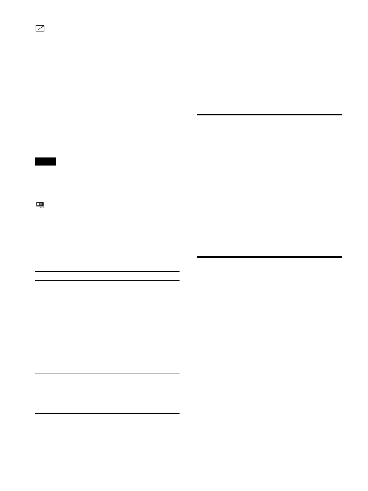
ユーザーコントロールメニュー
画質を調整するメニューです。
入力信号によって調整でき ない項目 は青色で 表示され ます。
サブメニュー 設定
オートクロマ/
フェーズ
色の濃さ(クロマ)と色相(フェーズ)を
調整します。
・ オート調整値:自動調整値のオン、オフ
の切り換えを設定します。「オフ」を
選択するとクロマとフェーズの値が
工場出荷値になり、「オン」を選択す
ると自動調整値になります。
・ 調整スタート:カラーバー信号(フル/
SMPTE/EIA)を画面に出して、
ENTER/SELECT ボタンを押すと、
自動的にオート調整画面が始まりま
す。調整終了後、MENU/EXITボタ
ンを押して戻ります。調整が正常終
了した場合、「オート調整値」は自動
的に「オン」になります。
ご注意
フルカラーバーの場合、必ず 8 本カラー
バーを入力してください。
ユーザー設定メニュー
言語の選択や、RGB とコンポーネントの切り換えなどを
設定します。
サブメニュー 設定
RGB/COMP 切換
(PVM‑14L2/PVM‑
20L2 のみ)
コンポーネントレベル以下の 3 種類の中から、入力されているコ
NTSC セットアップ NTSC 信号のセットアップのレベルを選択
フォーマット表示 入力信号のフォーマットを画面に表示させ
言語 メニューやメッセージの表示言語を以下の
RGB/COMPONENT 入力端子からの信号
をモニターするときに、入力する信号に応
じて「RGB」または「コンポーネント」を
選択します。
ンポーネント信号の種類を選択します。
「SMPTE」:100/0/100/0 のコンポー
ネント信号のとき
「BETA7.5」:100/7.5/75/7.5のコン
ポーネント信号のとき
「BETA0」:100/0/75/0 のコンポーネ
ント信号のとき
します。日本では0 で、アメリカでは 7.5
で運用されています。このため輸入ソフト
には 7.5 のものがあります。
るかどうかを設定します。
「オン」:常に表示
「オフ」:常に非表示
「オート」:信号入力開始後約 10 秒間だ
け表示
7 言語から選択できます。
「日本語」
「ENGLISH」:英語
「DEUTSCH」:ドイツ語
「FRANÇAIS」:フランス語
「ITALIANO」:イタリア語
「ESPAÑOL」:スペイン語
「」:中国語
メニューを使った調整
14

サブメニュー 設定
デガウスディレイ 電源を入れてから自動消磁機能が働くまで
の秒数を、0 から 99 秒の間で設定できま
す。
キャプションビジョ
ン(キャプションビ
ジョン(クローズド
・キャプション)デ
コーダー装着時のみ)
キャプションの表示モードを設定します。
「オフ」、「キャプション 1」、「キャプション
2」、「テキスト 1」、「テキスト 2」から選択
します。
リモートメニュー
PARALLELREMOTE 端子で機能を変更したいピンを選
択します。
1 〜 4、6 〜 8 ピンに各機能を割り付けられます。割り付
け可能な機能は以下のとおりです。
・ – –(機能の割り付けなし。)
・LINEA
・LINEB
・ RGB/COMP(PVM‑14L2/PVM‑20L2 のみ)
・OPTIONA
・OPTIONB
・ タリー
・ アンダースキャン
・ 16:9
・ 外部同期
・ ブルーオンリー
・ デガウス
ご注意
パラレルリモートを使用する場合は、配線が必要です。
◆詳しくは 18 ページをご覧ください。
オプションボード BKM‑150CP 装着時:
サブメニュー 設定
信号方式 信号方式を設定します。
「SDTI‑CP」あるいは「D1‑SDI」を選択し
ます。
オーディオ オーディオチャンネルを設定します。
D1‑SDIの場合
CH1 + CH2 〜 CH15 + CH16、CH1 〜
CH16 の中から選択できます。
SDTI‑CP の場合
CH1 + CH2 〜 CH7 + CH8、CH1 〜
CH8 の中から選択できます。
OPTIONAUDIOINPUT1または 2 入力
端子からの信号は無効になります。
タイムコード タイムコード表示を選択します。
D1‑SDIの場合
「VITC」、「RP188」、「オフ」の中から選択
できます。
SDTI‑CP の場合
「VITC」、「CP‑TC1」、「CP‑TC2」、「ES‑
TC1」、「ES‑TC2」、「オフ」の中から選択で
きます。
メニュー上の略称は以下の規格に対応しています。
・ CP‑TC1:SMPTE331MSystemItemUSERDATE/TIME
STAMP
・ CP‑TC2: SMPTE331M System Item CREATION DATE/TIME
STAMP
・ ES‑TC1:SMPTE328MMPEGESEditingInformationTIME
CODE1
・ ES‑TC2:SMPTE328MMPEGESEditingInformationTIME
CODE2
・ RP 188:SMPTERP188Time Code
・ VI TC :SMPTE12MVITC、SMPTE26 6MD‑VITC
オプション設定メニュー
後面に装着されたオプションボードの設定をします。
装着されたボードにより、表示される画面が異なります。
なお、何も装着されていない場合は、項目は表示されま
せん。入力信号を割り付けた後、モニターのオートクロ
マ / フェーズ調整を必ず行ってください。
オプションボード BKM‑155DV 装着時:
サブメニュー 設定
オーディオ オーディオチャンネルを設定します。
CH1 + CH2、CH3 + CH4、CH1/3、
CH2/4、CH1/3 + CH2/4、CH1 〜 CH4
の中から選択できます。
OPTIONAUDIOINPUT1または 2 入力
端子からの信号は無効になります。
オプションボード BKM‑120D/BKM‑129X 装着時:
シリアルナンバーが表示されます。
BKM‑150CP、BKM‑155DV内蔵の冷却ファンが止まっ
ている場合には、画面に常に「BKM‑xxxxx ファンエ
ラー」と赤く表示され、オプション A、オプション B は
選択できなくなります。
メニューを使った調整
15

故障かな?と思ったら
主な仕様
お買い上げ店などにご相談いただく前に、次の事項をご
確認ください。
・ 画面が緑色や紫色になるt入力ボタンを押して、正し
い入力を選んでください。
・ RGB/COMPONENT 入力端子に入力している信号が
表示されない(PVM‑14L2/PVM‑20L2 のみ)
ユーザー設定メニューの「RGB/COMP 切換」を入力
中の信号に合わせて設定してください。
・ BKM‑150CP、BKM‑155DV 装着時に「BKM‑
xxxxx ファンエラー」と表示され、オプション A、オ
プション B が選択できないtBKM‑xxxxx を修理に
出してください。
t
保証書とアフターサービ
ス
保証書
・ この製品には保証書が添付されていますので、お買い上
げの際お受け取りください。
・ 所定事項の記載内容をお確かめのうえ、大切に保存して
ください。
アフターサービス
調子が悪いときはまずチェックを
この説明書をもう一度ご覧になってお調べください。
それでも具合の悪いときはサービスへ
お買い上げ店、またはソニーサービス窓口にご相談くだ
さい。
保証期間中の修理は
保証書の記載内容に基づいて修理させていただきます。
詳しくは保証書をご覧ください。
保証期間経過後の修理は
修理によって機能が維持できる場合は、ご要望により有
料修理をさせていただきます。
一般
PVM‑9L3/PVM‑9L2
CRT: HR トリニトロン(P22 蛍光体)
(PVM‑9L3)
トリニトロン(P22 蛍光体)
(PVM‑9L2)
電源: AC100 〜 240V、50/60Hz
消費電流/電力:
最大 58W 0.6 〜 0.3A( 別売りの
BKM‑150CP 装着時)
12VDC、4.2A、48W
標準 47W 0.5 〜 0.25A(オプショ
ンボードなしの場合)
12VDC、3.3A、38W
最大外形寸法(幅/高さ/奥行き):
約 217 × 218 × 373mm
質量: 約 8.0kg
PVM‑14L2
CRT: トリニトロン(P22 蛍光体)
電源: AC100 〜 240V、50/60Hz
消費電流/電力:
最大 85W 0.9 〜 0.4A( 別売りの
BKM‑150CP 装着時)
標準 75W 0.8 〜 0.35A(オプショ
ンボードなしの場合)
最大外形寸法(幅/高さ/奥行き):
約 346 × 340 × 430mm
質量: 約 18.0kg
PVM‑20L2
CRT: トリニトロン(P22 蛍光体)
電源: AC100 〜 240V、50/60Hz
消費電流/電力:
最大 108W 1.1 〜 0.5A( 別売りの
BKM‑150CP 装着時)
標準 98W 1.0 〜 0.4A(オプション
ボードなしの場合)
最大外形寸法(幅/高さ/奥行き):
約 453 × 463 × 529mm
質量: 約 33.0kg
入出力
故障かな?と思ったら/保証書とアフターサービス/主な仕様
16
入力
LINEA 入力端子
Y/C 入力 4 ピンミニ DIN(1)

VIDEO 入力 BNC 型(1)1Vp‑p + 3dB
− 6dB負同期
AUDIO 入力 ピンジャック(1)− 5dBu47kΩ
以上
LINEB入力端子
VIDEO 入力 BNC 型(1)1Vp‑p + 3dB
− 6dB負同期
AUDIO 入力 ピンジャック(1)− 5dBu47kΩ
以上
RGB/ コンポーネント入力端子 BNC 型(3)(PVM‑
14L2/PVM‑20L2 のみ )
RGB 入力 0.7Vp‑p + 3dB− 6dB(Sync
OnGreen0.3Vp‑p 負同期)
コンポーネント入力
0.7Vp‑p + 3dB− 6dB(75%
クロミナンス標準カラーバー信
号時)
AUDIO 入力 ピンジャック(1)− 5dBu
47kΩ 以上
外部同期入力端子
BNC 型(1)0.3 〜 8Vp‑p正負両
極性 3 値または負極性 2 値
オプション AUDIO 入力端子
ピンジャック(2)
−5dBu47kΩ以上
リモート入力
パラレルリモート
モジュラーコネクター 8 ピン(1)
出力
LINEA 出力端子
Y/C 出力 4 ピンミニ DIN(1)ループス
ルー、75Ω 自動終端機能付き
VIDEO 出力 BNC 型(1)ループスルー、75Ω
自動終端機能付き
AUDIO 出力 ピンジャック(1)ループスルー
LINEB出力端子
VIDEO 出力 BNC 型(1)ループスルー、75Ω
自動終端機能付き
AUDIO 出力 ピンジャック(1)ループスルー
RGB/ コンポーネント出力端子
(PVM‑14L2/PVM‑20L2 のみ)
RGB /コンポーネント出力
BNC 型(3)ループスルー、75Ω
自動終端機能付き
AUDIO 出力 ピンジャック(1)ループスルー
外部同期出力端子
BNC 型(1)ループスルー、75Ω
自動終端機能付き
内蔵スピーカー出力
0.8W(モノラル)
映像信号系
周波数特性 PVM‑9L3/PVM‑9L2
50Hz 〜 6MHz(0dB/ − 3dB)
PVM‑14L2/PVM‑20L2
50Hz 〜 10MHz(0dB/ − 3dB)
アパ−チャ−補正量
1)
OFF:0dB
ON:2 〜 6dB
画像系
ノーマルスキャン
CRT 有効画面の 6% オーバースキャン
(PVM‑9L3/PVM‑9L2)
CRT 有効画面の 7% オーバースキャン
(PVM‑14L2/PVM‑20L2)
アンダースキャン
CRT 有効画面の 5% アンダースキャン
直線性 PVM‑9L3/PVM‑9L2
H:4% 以下
V:4% 以下
PVM‑14L2
H:4% 以下
V:4% 以下
PVM‑20L2
H:5% 以下
V:5% 以下
色温度 D65、D93、ユーザー設定(調整可能
色温度 5000K 〜 10000K)
コンバージェンスエラー
PVM‑9L3/PVM‑9L2
中心部:0.4mm 以下
周辺部:0.5mm 以下
PVM‑14L2
中心部:0.4mm 以下
周辺部:0.5mm 以下
PVM‑20L2
中心部:0.5mm 以下
周辺部:0.7mm 以下
ラスターサイズ安定度
H:1.0%
V:1.0%
解像度 ( 中心部 ) 450TV 本 (PVM‑9L3)
250TV 本 (PVM‑9L2)
600TV 本 (PVM‑14L2/PVM‑20L2)
1) RGB入力時はアパーチャーの補正は行えません。
主な仕様
17

動作条件
温度 0 〜 35 ℃
湿度 30 〜 85% 以下 ( 結露のないこと )
気圧 700 〜 1060hPa
ピン配列
PARALLELREMOTE 端子
モジュラーコネクター
(8 ピン)
1
8
保存・輸送条件
温度 − 10 〜 40 ℃
湿度 0 〜 90%
気圧 700 〜 1060hPa
付属品
AC 電源コード (1)
ACプラグホルダー (1)
取扱説明書 (1)
保証冊子 (1)
本機は「JISC61000‑3‑2適合品」です。
本機は業務用トリニトロンカラービデオモニターです。
本機の仕様および外観は、改良のため予告なく変更する
ことがありますが、ご了承ください。
ピン番号 機能
1入力信号LINEAを指定
2 入力信号LINEBを指定
3 タリーランプのON/OFF
4 アンダースキャンの選択
5GND
6 ブルーオンリーのON/OFF
7 アスペクト比16:9の選択
8 外部同期の選択
機能割り付けは、リモートメニューで変更できます。
リモートコントロールを使用するための配線
リモートコントロールで使用したい機能をアース(5 ピ
ン)に接続します。
18
主な仕様

主な仕様
19

Owner’s Record
The model and serial numbers are located at the rear.
Record these numbers in the spaces provided below.
Refer to these numbers whenever you call upon your
Sony dealer regarding this product.
Model No. ____________________
Serial No. ____________________
WARNING
To prevent fire or shock hazard, do not expose
the unit to rain or moisture.
Dangerously high voltage are present inside
the unit.
Do not open the cabinet. Refer servicing to
qualified personnel only.
In the event of a malfunction or when m aintenance is
necessary, consult an authorized Sony dealer.
For the customers in the U.S.A.
This equipment has been tested and found to comply
with the limits for a Class A digital device, pursuant to
Part 15 of the FCC Rules. These limits are designed to
provide reasonable protection against harmful
interference when the equipment is operated in a
commercial environment.
This equipment generates, uses, and can radiate radio
frequency energy and, if not installed and used in
accordance with the instruction manual, may cause
harmful interference to radio communications.
Operation of this equipment in a residential area is like ly
to cause harmful interference in which case the user will
be required to correct the interference at his own
expense.
Y o u are cautioned that any c hanges or modif ications n ot
expressly approved in this manual could void your
authority to operate this equipment.
For the customers in Canada
This Class A digital apparatus complies with Canadian
ICES-003.
Pour les utilisateurs au Canada
Cet appareil numérique de l a classe A est con forme à la
norme NMB-003 du Canada.
For the customers in Europe
This product with the CE marking complies with both
the EMC Directive (89/336/EEC) and the Low Voltage
Directive (73/23/EEC) issued b y the Commission of the
European Community.
Compliance with these directiv es impl ies conformit y to
the following European standards:
• EN60950: Product Safety
• EN55103-1: Electromagnetic Interference (Emission)
• EN55103-2: Electromagneti c Suscepti bi lit y
(Immunity)
This product is int en ded for use in the following
Electromagnetic Environment(s):
E1 (residential), E2 (commercial and light industrial),
E3 (urban outdoors) and E4 (controlled EMC
environment, ex. TV studio).
These products are designed for operation in the
environments E1 to E4. During EMC stress, the
performance (evaluated according to ITU/R 562-3 and
ITU/R 500-4) may degrade as sho wn in T able 1. Without
the EMC stress, all performance will recover to full
function.
Table 1
Frequency Level
PVM-14L2
(14-inch Monitor)
PVM-20L2
(20-inch Monitor)
A TTENTION – When the product is installed in a
rack:
a) Elevated operating ambient temperature
If installed in a closed or multi-unit rack assembl y,
the operating ambient temperature of the rack
environment may be greater than room ambient.
Therefore, consideration should be given to installing
the equipment in an environment compatible with the
manufacture’s maximum rated ambient temperature
(Tmra: 0°C to 35°C (32°F to 95°F)).
b) Reduced air flow
Installation of the equipment in a rack should be such
that the amount of air flow required for safe
operation of the equipment is not compromised.
c) Mechanical loading
Mounting of the equipment in the rack should be
such that a hazardous condition is not achieved due
to uneven mechanical loadin g.
d) Circuit overloading
Consideration should be given to the connection of
the equipment to the supply circuit and the ef fect that
overloading of circuits might have on overcurrent
protection and supply wiring.
Appropriate consideration of equipment nameplate
ratings should be used when addressing this concern.
e) Reliable earthing
Reliable earthing of rack-mou nted equipment should
be maintained. Parti cular attention should be gi ven to
supply connections other than direct connections to
the branch circuit (e.g., use of power strips).
f) Gap keeping
Upper and lower gap of rack-mounted equipment
should be kept 44 mm (1
210 – 340 MHz/
625 – 655 MHz
259 – 346 MHz/
385 – 457 MHz
3
/4 inches).
3.5
3.5
20
Table of Contents
Precaution ............................................................22
On Safety ..........................................................22
On Installation ..................................................22
On Cleaning of the CRT Surface ......................22
On Cleaning ......................................................22
On Repacking ...................................................22
On Mounting on a Rack ...................................22
Features ................................................................22
Connections .......................................................... 23
How to Connect the AC Power Cord ...............23
Location and Function of Parts and Controls .. 24
Control Panel ....................................................24
Rear Panel ........................................................25
Selecting the Menu Language ............................26
Using the Menu ....................................................27
Adjustment Using the Menus .............................28
Items ................................................................. 28
Adjusting and Changing the Settings ...............28
STATUS menu ...........................................28
COLOR TEMP/BAL menu .......................28
USER CONTROL menu ............................29
USER CONFIG menu ................................29
REMOTE menu .........................................30
OPTION CONFIG menu ...........................30
Troubleshooting ................................................... 30
Specifications ........................................................31
Dimensions .....................................................i
How to install the battery (for the PVM-9L3/
PVM-9L2 only) ............................Back cover
GB
The explanatio n giv en in this manual can be appl ied to
the following models unless noted otherwise.
When the explanation differs among models, this is
clearly indicated in this manual.
• PVM-9L3 (9-inch monitor )
• PVM-9L2 (9-inch monitor )
• PVM-14L2 (14-inch monitor)
• PVM-20L2 (20-inch monitor)
Unless indicated otherwise, illustrations o f the video
monitor are of the PVM-14L2.
21

Precaution
On Safety
• Operate the unit only with a po wer source as specified
in the “Specifications” section.
• A nameplate indicating operating voltage, power
consumption, etc., is located on the rear panel.
• Should any solid obj ect or li qu id fall into the cabinet ,
unplug the unit and have it checked by qualified
personnel before operating it any further.
• Do not drop or place heavy objec ts on the power co rd.
If the power cord is damaged, turn off the power
immediately. It is dangerous to use the unit with a
damaged power cord.
• Unplug the unit from th e wall outlet if it is not to be
used for several days or more.
• Disconnect the power cord from the AC outlet by
grasping the plug, not by pulling the cord.
• The socket-outlet shall be installed near the equipment
and shall be easily accessible.
On Installation
• Allow adequate air circulat ion to prev ent internal heat
build-up.
Do not place the unit on surfaces (rugs, bl ankets, etc.)
or near materials (curtains, draperies) that may block
the ventilation holes.
• Do not install the u nit in a location near h eat sources
such as radiators or air ducts, or in a place subject to
direct sunlight, excessive dust, mechanical vibration
or shock.
On Repacking
Do not throw away the carton and packing materials.
They make an ideal container which to transport the
unit. When shipping th e unit to another location , repack
it as illustrated on the carton.
On Mounting on a Rack
Leave 1U space empty above and below the monitor to
ensure adequate air circulation or install a fan to
maintain the monit or ’s performance.
If you have any questions about this unit, contact your
authorized Sony dealer.
Features
Picture
Trinitron1) picture tube
Trinitron tube provides a picture whose horizontal
resolution is more than 600 TV lines at the center of the
picture (for the PVM-14L2/PVM-20L2 only).
Comb filter
When NTSC video signals are receiv ed, a comb filter is
activated to enable more accurate Y/C separation. This
contributes to less of a decrease in resolution, and less
cross color and cross luminance phenomena.
Beam current feedback circuit
The built-in beam current feedback circuit assures stable
white balance.
On Cleaning of the CRT Surface
• Clean the CRT with a soft cloth.
When the CRT is dirtied with oily hands or
fingerprints, clean it with a soft cloth moistened with
a mild detergent solution.
• Never use abrasive cleansers, alkaline soap, strong
solvents such as alcohol, thinne r or benzine, since they
will damage the surface.
• Do not rub the surface of the CRT with a solid object
or hit it.
On Cleaning
T o keep the unit l ooking brand-ne w , periodically clean it
with a mild detergent solut ion. Never use strong solv ents
such as thinner or benzine, or abrasive cleansers since
they will damage the cabinet. As a safety precaution,
unplug the unit before cleaning it.
1)“Trinitron” is a registered trademark of Sony Corporation.
22
Precaution / Features
Two color systems available
The monitor can display both NTSC and PAL signals.
The color system of the input sig nal is automatically
detected.
Input
Analog RGB/component inp ut co nn ec to rs (for
the PVM-14L2/PVM-20L2 only)
Analog RGB or component (Y, P
video equipment can be input through the se connectors.
Press the RGB/COMPONENT button on the control
panel to monitor the si gnal.
Y/C input connector (S-input connector)
A video signal, split into a luminance component (Y)
and a chrominance component (C), can be input thro ugh
this connector, eliminating the interference between the
two components, ensuring picture quality.
, PR) signals from
B

Expandable input capability
You can easily e xpand the input capabilit y b y installing
an optional board (not supplied) in the opti on slot on the
rear panel. Only one board for expanding the input
capability can be installed at a time. If you install two
boards, they do not function.
External sync input
Pressing the EXT SYNC button on the control panel
once enables the monitor to operate on a sync signal
supplied from an external sync generator.
Automatic termination (on ly for connectors
with a mark)
The input connector is te rminated at 7 5 ohms inter nally
when nothing has been connected to the output
connector. If a cable is connected to the output
connector, the internal terminal is automatically released
and the signals input to t he input connect or are output to
the output connector (loop-through).
Functions
Options
EIA 19-inch rack mount bracket available
The monitor can be mounted on an EIA-standard
19-inch rack, using the following mounting brackets or
slide rails.
For the PVM-9L3/PVM-9L2: MB-520
For the PVM-14L2: MB-502B (In Europe, use the MB-
502C)
For the PVM-20L2: SLR-103A (In Europe, use the
SLR-103C)
F or details on mounting the monitor on the rack, refer to
the user’s manual of the mounting bracket or slide rail.
Caption Vision (Closed Caption) Decoder
available
Installing certain optional parts enables the monitor to
decode Closed Caption signals. Using a menu, you can
choose whether or not to display captions (subtitles) and
can select the style of the captio n di spla yed. For details
on these parts, consult your Sony dealer.
Auto chroma phase function
The chroma and phase are automatically adjusted.
Blue only mode
In the blue only mode, the blue component of an input
signal is displayed. This facilitates adjustments of the
color saturation and phase, and observation of VCR
noise.
Underscan mode
In the underscan mod e, the lines usually sc anned outside
the normal display area are visible so that you can
monitor the entire screen area.
Note
When the monitor is in the underscan mode, dark RGB
scanning lines appear on the top edge of the screen.
These are caused by an internal test signal.
16:9 mode
Y o u can precisely monitor a signa l whose aspect ratio is
16:9, in addition to a 4:3 signal.
Auto/manual degaussing
The monitor is automaticall y degaussed when the po wer
is turned on. You can manually degauss the monitor by
pressing the DEGAUSS button.
Using the menu, you can preset a time to degauss
automatically after the power has been turned on for a
while.
On-screen menus
Y o u can set color temperature, perform a chro ma set up,
and make other settings using the on-screen menus.
Connections
How to Connect the AC P o wer Cor d
To connect the AC power cord
Plug the AC power cord into the AC IN socket. Then,
attach the AC plug holder (supplied) to the AC power
cord and slide it over the cord until it locks.
AC IN socke t
AC power cord
lock levers
AC plug holder
To remove the AC power cord
Pull out the AC plug holder while pressing the lock
levers.
For the PVM-9L3/PVM-9L2, you can use a Sony
lithium-ion battery, the BP-L60A/BP-L90A, or a Sony
nickel metal hydride battery, the BP-M50/BP-M100.
For details on installing the battery, see “How to install
the battery” on back cover.
Connections
23

Location and Function of Parts and Controls
Control Panel
w;
ql
qkqjqhqg
LINEALINE
DEGAUSS
RESET
BLUE
ONLY
B
RGB/
COMPONENT
UNDER
SCAN
OPTION
A
16 : 9
OPTION
B
EXT
SYNC
MENU
EXIT
SELECT
ENTER
–+
PHASECHROMABRIGHT
MAX
MIN
PUR GRN MIN MAX MIN MAX
CONTRAST
VOLUME
POWER
q;qsqdqf
a POWER ! switch
Press this switch to turn on the monitor. The lamp will
light up. Press this switch again to turn off the monitor.
b VOLUME c ontrol
c CONTRAST control
d PHASE control
Note
When you use a P AL or component signal, phase ca nnot
be adjusted.
e CHROMA control
f BRIGHT (brightness) control
g MENU/EXIT button
Press this button to show or hide on-screen menus.
h ENTER/SELECT button
Press this button to confirm an item selected on the menu.
i M/+ (move the cursor up/adjust the value)
button
m/– (move the cursor down/adjust the value)
button
Press these buttons to move the cursor or adjust an item
selected on the menu.
j EXT SYNC (external sync) button and lamp
Press this button to operate the monitor synchro nized
with an external sync signal input through the EXT
SYNC connector.
123456789qa
k 16:9 button and lamp
Press this button to monitor a signal whose aspect ratio
is 16:9.
l UNDERSCAN button and lamp
Press this button for underscanning.
The display size is reduced b y approximately 5% so that
the four corners of the picture are visible.
m BLUE ONLY/RESET button and lamp
• As the BLUE ONLY button, press this button to
eliminate the red and green component of input
signals. Only the blue component of an in put signal is
displayed on the screen. This facilitates adjustments of
chroma and phase, and observation of VCR noise.
(Phase adjustment is effective only for NTSC signals.)
• As the RESET button, you can reset the menu item
setting to the previous one by pressing this button
while the new item is being selected and adjusted.
n DEGAU SS button and lamp
Press this button only once. The screen will be
demagnetized. W ait for 10 minu tes or more before using
this button again.
Note
The DEGAUSS button is disabled when the screen
menu is being displayed.
To manually degauss the moni tor, first, exit the screen
menu by pressing the MENU/EXIT button.
o LINE A button and lamp
Press this button to monitor the signal input through the
LINE A connectors.
24
Location and Function of Parts and Controls
p LINE B button and lamp
Press this button to monitor the signal input through the
LINE B connectors.

q RGB/COMPONENT button and lamp (for the
PVM-14L2/PVM-20L2 only)
Press this button to moni tor the signal in put through the
RGB/COMPONENT connectors.
r OPTION A button and lamp
This button works when an optional board has been
installed in the option slot on the rear panel. Press this
button to monitor the video sig nal input th rough input 1
of the optional board and th e audio signal input through
the OPTION AUDIO INPUT 1 jack.
Rear Panel
s OPTION B button and lamp
This button works when an optional board has been
installed in the option slot on the rear panel. Press this
button to moni tor the video sign al input thro ugh input 2
of the optional boa rd an d the audio signa l input thro ugh
the OPTION AUDIO INPUT 2 jack.
(This button is disa bled if BKM- 129X or BKM-15 5DV
is used.)
t Tally lamp
Lights up when a video camera connected to this
monitor is selected. For the tally lamp to function
properly, certain cabling is required.
For details on this cabling, see page 33.
PVM-14L2/PVM-20L2
1
2
a Option slot
You can install one optional board for expanding input
capability in this option slot. If you install two boards,
they do not function.
For details on how to install a boar d, refer to t he use r’s
manual supplied with the optional board.
b AC IN socket
Connect the supplied AC power cord to this socket and
then to a wall outlet.
345678
AC IN LINE A LINE B
IN OUT
IN
VIDEO
AUDIO
IN OUT
OUT
IN
RGB/COMPONENT
G/Y
IN OUT
OUT
B/PB
IN OUT IN
R/P
VIDEO
AUDIO AUDIO
R
PVM-9L3/PVM-9L2
LINE A
IN OUT
1
LINE A
IN OUT
IN OUTVIDEO
IN
OUT
PARALLEL REMOTE
IN OUT
EXT
SYNC
OUT
OPTION AUDIO INPUT
1 2
AUDIO
PARALLEL
REMOTE
LINE B
IN OUTVIDEO
–+
DC
IN OUT
AUDIO
12V IN
EXT SYNC
IN OUT
12
129X
OPTION AUDIO INPUT
AC IN
2
VIDEO IN/OUT (BNC)
These are the input /output c onnectors for a comp osite
video signal. Connect them to the composite video
input/output connecto rs on equipment such as a VCR,
video camera, or another monitor.
AUDIO IN/OUT (phono jack)
These are the input/output jacks for an audio signal.
Connect them to the audio input/output jacks on
equipment such as a VCR.
IN OUTVIDEO
IN
PARALLEL
REMOTE
IN OUTVIDEO
IN OUT
IN OUT
9q;
12
OPTION AUDIO INPUT
OUTAUDIO
LINE B
AUDIO
EXT SYNC
3
7
4
6
8
c LINE A connectors
Line input connectors for Y/C separate, composite video
and audio signals and their loop-through output
connectors.
Press the LINE A b utton on th e control panel to monitor
the input signal through these connectors.
If you input signals to both Y/C IN and VIDEO IN, the
signal input to the Y/C IN is selected.
Y/C IN/OUT (4-pin mini-DIN)
These are the input/output connectors for a Y/C
separate signal. Connect them to the Y/C separate
input/output connect ors on equipment such as a VCR,
video camera, or another monitor.
d LINE B connectors
Line input connectors for composite video and audio
signals and their loop-through output connectors.
Press the LINE B button on the control panel to monitor
the signal input through these connectors.
VIDEO IN/OUT (BNC)
These are the input /output c onnectors for a comp osite
video signal. Connect them to the composite video
input/output connecto rs on equipment such as a VCR,
video camera, or another monitor.
Location and Function of Parts and Controls
25
AUDIO IN/OUT (phono jack)
These are the input/output jacks for an audio signal.
Connect them to the audio input/output jacks on
equipment such as a VCR.
e RGB/COMPONENT connectors (for the PVM-
14L2/PVM-20L2 only)
Analog RGB signal or component (Y, P
, PR) signal
B
input connectors and their loop-through output
connectors.
Press the RGB/COMPONENT button on the control
panel to monitor the signal input through these
connectors.
G/Y, B/P
, R/PR IN/OUT (BNC)
B
These are the input/output connectors for an analog
RGB and a component (Y, P
, PR) signal. Unless an
B
external sync signal is input, the monitor is
synchronized with the sync signal contained in the G/
Y signal.
AUDIO IN/OUT (phono jack)
When using an analog RGB or a component signal as
a video signal, use these jacks for the input/output of
an audio signal. Connect them to the audio input/
output jacks on equipment such as a VCR.
This product is intended to be supplied by a Listed
Power Unit marked “Class 2” and rated 12 V dc, 4.2 A.
j Battery attachment (for the PVM-9L3/PVM-
9L2 only)
Install the battery here. For the PVM-9L3/PVM-9L2, a
Sony lithium-ion battery, the BP-L60A/BP-L90A, or a
Sony nickel metal hydride battery, the BP-M50/BPM100, is applicable.
Selecting the Menu
Language
You can select one of seven languages (English,
German, French, Italian, Spanish, Japanese, Chinese)
for displaying the menus and other on-screen messages.
The factory preset language is ENGLISH (English).
The current settings are displayed in place of the
marks on the illustrations of the menu screen.
f EXT SYNC (external sync) connectors
Press the EXT SYNC button on the control panel to use
an external sync signal.
IN/OUT (BNC)
These are the input/output connectors for an external
sync signal. Input a reference signal generated by a
sync generator to the IN connector. Connect the OUT
connector to an external sync signal input connector
on equipment which you intend to synchronize with
this monitor.
g PARALLEL REMOTE terminal (modular
connector)
Forms a parallel switch and controls the monitor
externally.
For details on the pin assignment and factory setting
function assigned to each pin, see page 33.
h OPTION AUDIO INPUT 1, 2 input connectors
If an optional board has been installed in the option slot,
input an audio signal into these connectors. You can
connect up to 2 systems. To monitor the audio signals
input to OPTION AUDIO INPUT 1 or 2, press either the
OPTION A or OPTION B button.
i DC 12V IN connector (XLR) (for the PVM-9L3/
PVM-9L2 only)
Plug the DC 12V power supply to this connector to
provide power to the monitor.
MENU/EXIT
button
B
RESET
BLUE
ONLY
RGB/
COMPONENT
UNDER
SCAN
LINEALINE
DEGAUSS EXT
M/+, m/– button
1
Press the MENU/EXIT button to display the menu
OPTION
A
16 : 9
OPTION
B
SYNC
MENU
EXIT
SELECT
ENTER
ENTER/SELECT
button
screen, and press the M/+ or m/– button to select
(USER CONFIG), then press the ENTER/
SELECT button.
The USER CONFIG menu appears.
U S E R C O N F I G
x R G B / C O M P S E L x x x x
C O M P L E V E L x x x x x
N T S C S E T U P x
F O R M A T D I S P x x x x
L A N G U A G E E N G L I S H
D E G A U S S D E L A Y x
2
Press the M/+ or m/– button to select “LANGUAGE,”
then press the ENTER/SELECT button.
26
Selecting the Menu Language

The selected item is displayed in yellow.
U S E R C O N F I G
R G B / C O M P S E L x x x x
C O M P L E V E L x x x x x
N T S C S E T U P x
F O R M A T D I S P x x x x
x L A N G U A G E E N G L I S H
D E G A U S S D E L A Y x
3
Press the M/+ or m/– button to select the desired
language, then press the ENTER/SELECT button.
The on-screen language changes to the language
you have selected.
To clear the menu
Press the MENU/EXIT button.
The menu disappears automatically if a button is not
pressed within one minute.
Using the Menu
The monitor is equipped with an on-screen menu for
making various adju stments and settin gs such as picture
control, input setting, set setting change, etc.
Follow the instructions below to make adjustments or to
change settings.
1
Press the MENU/EXIT button.
The menu appears.
The menu presently selected is indicated by a
yellow button.
S T A T U S
F O R M A T x x x x x x x x x
x x x x x x x x
C O L O R T E M P x x x
C O M P L E V E L x x x x x
N T S C S E T U P x
R G B / C O M P S E L x x x x
O P T I O N
2
Press the M/+ or m/– button to select a menu, then
press the ENTER/SELECT button.
The menu icon presently selected is shown in
yellow and the available setting items are displayed.
Menu Setting items
U S E R C O N F I G
x R G B / C O M P S E L x x x x
C O M P L E V E L x x x x x
N T S C S E T U P x
F O R M A T D I S P x x x x
L A N G U A G E E N G L I S H
D E G A U S S D E L A Y x
3
Use the M/+ or m/– button to select the desired
item, then press the ENTER/SELECT button.
The item to be changed is displayed in yellow.
For details on the menu items, see “Adjustme nt Using
the Menus” on page 28.
Y ou can a lso change the menu lang uage displayed in the
on-screen menu.
To change t he men u l ang ua g e, see “Selecting the Menu
Language” on page 26.
The current settings are displayed in place of the
marks on the illustration s of the menu screen.
1
OPTION
A
16 : 9
OPTION
B
SYNC
MENU
EXIT
SELECT
ENTER
2, 3, 4
RESET
BLUE
ONLY
B
RGB/
COMPONENT
UNDER
SCAN
LINEALINE
DEGAUSS EXT
RESET button
Note
If the menu consists of multiple pages, press the
M/+ or m/– button to go to the desired menu page.
4
Make the setting or adjustm ent in an item.
When changing the adjustment level:
To increase the number, press the M/+ button.
To decrease the number, press the m/– button.
Press the ENTER/SEL ECT button to confirm the
number, then restore the original screen.
When changing the setting:
Press the M/+ or m/– button to change the setting.
Press the ENTER/SEL ECT button to confirm the
setting.
Note
An item displayed in blue cannot be accessed. You can
access the item if it is displayed in white.
To clear the menu
Press the MENU/EXIT button.
The menu disappears automatically if a button is not
pressed within one minute.
Using the Menu
27
About retaining the settings
The settings are automatically stored in the monitor
memory.
Adjusting and Changing the
Settings
To reset items being adjusted
Press the RESET button while the new menu item is
being selected and adjusted. Any changes to this new
item setting is ignored and the item is reset to the
previous setting.
Adjustment Using the
Menus
Items
The screen menu of this monitor consists of the
following items.
STATUS
COLOR TEMP/BAL
USER CONTROL
USER CONFIG
REMOTE 1 PIN
OPTION CONFIG
1)
4)
COLOR TEMP
MANUAL ADJ
AUTO CHROMA/PHASE
SUB CONTROL
RGB/COMP SEL
COMP LEVEL
NTSC SETUP
FORMAT DISP
LANGUAGE
DEGAUSS DELAY
CAPTION
2 PIN
3 PIN
4 PIN
6 PIN
7 PIN
8 PIN
2)
3)
STATUS menu
The STATUS menu is us ed to display the current status
of the monitor.
Submenu Setting
FORMAT Display only
COLOR TEMP Display only
COMP LEVEL Display only
NTSC SETUP Display only
RGB/COMP SEL Display only (for the PVM-14L2/
PVM-20L2 only)
OPTION Display only
COLOR TEMP/BAL menu
The COLOR TEMP/BAL menu is used for adjusting the
picture white balance.
You need to use a measurement instrument to adjust the
white balance.
Submenu Setting
COLOR TEMP Select the colo r te mperature from
among D65, D93 an d U SER
setting.
MANUAL ADJ If you set COLOR TEMP to USER,
the item displayed is c hanged from
blue to white, which means you can
adjust the color temperature.
• ADJUST GAIN...: Adjusts the
color balance (GAIN).
• ADJUST BIAS...: Adjusts the
color balance (BIAS).
• COPY FROM: If you select
D65 or D93 with the M/+ or
m/– button, the white
balance data of the selected
color temperature will be
copied to USER.
1) The items on the STATUS menu indicate the current settings.
2) for the PVM-14L2/PVM-20L2 only
3) CAPTION is availa ble only when t he Caption Vision (Clos ed Caption)
Decoder has been installed.
4)The items on the OPTION CONFIG menu differ depending on the
optional board installed.
28
Adjustmen t U s ing the Menus

USER CONTROL menu
The USER CONTRO L menu is used for adjusting the
picture.
Items that cannot be adjusted depending on the input
signal are displayed in blue.
Submenu Setting
AUTO CHRO MA/
PHASE
SUB CONTROL You can finely adjust the
Adjusts color intensity (CHROMA)
and tones (PHASE).
• AUTO ADJ VALUE: Chooses
the values to be applied to
the chroma and phase from
auto adjustment or factory
settings.
ON: auto adjustment values
OFF: factory preset values
• START: Displays the color bar
signals (Full/SMPTE/EIA)
on the screen. To select one,
press ENTER/SELECT
button. The auto adjustm ent
function starts. After the
adjustment has been done
correctly, AUTO ADJ
VALUE is automatically set
to ON. Press the MENU/
EXIT button to exit the
adjustment screen.
Note
If you have selected full color bars,
be sure to enter eight color bars.
adjustment range of the following
controls on the control panel; the
CONTRAST, PHASE, CHROMA
and BRIGHT controls.
• ADJUST...: adjusts the
following items.
CONTRAST...: Adjusts the
picture contrast.
BRIGHT...: Adjusts the picture
brightness.
CHROMA...: Adjusts the color
intensity. The higher the
setting, the greater the
intensity.
The lower the setting, the
lower the intensity.
PHASE...: Adjusts color tones.
The higher the setting, the
more greenish the picture
becomes.
The lower the setting, the
more purplish t he picture
becomes.
APERTURE...: Adjusts the
picture sharpness. The higher
the setting, the sharper the
picture.
USER CONFIG menu
The USER CONFIG menu is used to select a language for
the menus and the on-screen messages or to determine the
type of video signal acceptable on the RGB/
COMPONENT connectors (Analog RGB or component).
Submenu Setting
RGB/COMP SEL
(for the PVM-14L2/
PVM-20L2 only)
COMP LEVEL Select the component level from
NTSC SETUP Select the NTSC setup level from
FORMAT DISP Determines whether the format of a
LANGUAGE Y ou can select the desired language
DEGAUSS DELAY Sets the delay time for auto
CAPTION
(available only when the
Caption Vision (Closed
Caption) Decoder has
been installed.)
According to the type of video
signal which you intend to input to
the RGB/COMPONENT
connectors, choose between RGB
and COMPONENT.
among three mode s .
SMPTE: 100/0/100/0 signal
BETA 7.5: 100/7.5/75/7.5 signal
BETA 0: 100/0/75/0 signal
two modes.
The 7.5 setup level is used mainly
in North America. The 0 setup level
is used mainly in Japan.
input signal is displayed on the
screen or not.
ON: The format is always
displayed.
OFF: The format is always
hidden.
AUTO: The format is displayed
for about 10 seconds when the
input of the signal begins.
for the menus or messages from the
following language options.
: Japanese
ENGLISH: English
DEUTSCH: German
FRANÇAIS: French
ITALIANO: Italian
ESPAÑOL: Spanish
: Chinese
degaussing to start working aft er
the power is turned on. The delay
time can be set within 0 to 99
seconds.
Selects the caption display mode
from among the following options:
OFF, CAPTION 1, CAPTION 2,
TEXT 1 and TEXT 2.
Adjustment Using the Menus
29
REMOTE menu
The REMOTE menu is used to assign the functions to
the pins of the PARALLEL REMOTE terminal.
Pin 1 to 4 and pin 6 t o 8 can be u sed. The fo llo wing li sts
the functions you can assign to the pins.
• – – (No function is assigned.)
•LINE A
•LINE B
• RGB/COMP (for the PVM-14L2/PVM-20L2 only)
•OPTION A
•OPTION B
•TALLY
• UNDERSCAN
• 16:9
• EXT SYNC
• BLUE ONLY
•DEGAUSS
Note
The following lists the abbreviations in the menu and their full
names:
• CP-TC1: SMPTE 331M System Item USER DATE/TIME
ST AMP
• CP-TC2: SMPTE 331M System Item CREATION DATE/
TIME STAMP
• ES-TC1: SMPTE 328M MPEG ES Editing Information
TIME CODE1
• ES-TC2: SMPTE 328M MPEG ES Editing Information
TIME CODE2
• RP188: SMPTE RP188 Time Code
• VITC: SMPTE 12M VITC, SMPTE 266M D-VITC
When instal ling the B KM-155D V option al boar d:
Submenu Setting
AUDIO Selects an audio channel.
Select from among CH1+CH2,
CH3+CH4, CH1/3, CH2/4, CH1/
3+CH2/4, or CH1 through CH4.
OPTION AUDIO INPUT 1/2 jack
is ignored.
If you use the parallel remote function, you need to
connect cables.
Fo r more details, see page 33.
OPTION CONFIG menu
The OPTION CONFIG menu is used to set the optional
board installed in the option slot on the rear panel.
Depending on the board installed, the screen displayed
may differ. If no board is installed, the item settings ar e
not displayed. After assigning the i nput signal, be sure to
adjust the monitor’s AUTO CHROMA/PHASE.
When installing the BKM-150CP optional board:
Submenu Setting
FORMAT Sets the signal type .
Select SDTI-CP or D1-SDI.
AUDIO Selects an audio channel.
D1-SDI
Select from am on g C H 1+ CH 2
through CH15+CH16, or CH1
through CH16 .
SDTI-CP
Select from am on g C H 1+ CH 2
through CH7+CH8, or CH1
through CH8.
The audio signal in put to the
OPTION AUDIO INPUT 1/2 jack
is ignored.
TIME CODE Selects the time code display.
D1-SDI
Select VITC, RP188 or O FF.
SDTI-CP
Select VITC, CP-TC1, CP-TC2,
ES-TC1, ES-TC2 or OFF.
When installing the BKM-120D or BKM-129X
optional board:
The serial number of the board is displayed on the
OPTION CONFIG menu.
If the cooling fan in the BKM-150CP or BKM-155DV
is stopped, the screen shows the following message in
red “BKM-xxxxx FAN ERROR”. In this case, you
cannot select Option A or Option B.
Troubleshooting
This section may help you isolate t he cause of a problem
and as a result, eliminate the need to contact technical
support.
• The display is colored green or purple. t Select
the correct input b y pressing one of the b uttons relate d
to input.
• The signal input through the RGB/COMPONENT
input connectors does not appear on t he screen (for
the PVM-14L2/PVM-20L2 only). t Set RGB/
COMP SEL on the USER CONFIG menu
appropriately according to type of input signal.
• The BKM-150CP or BKM-155DV has been
installed. The error message “BKM-xxxxx FAN
ERROR” is displayed and you cannot select
Option A or Option B. t Repair the BKM-xxxxx.
30
Troubleshooting
 Loading...