

Sony trinitron PVM-1450QM,trinitron PVM-1454QM Service Manual
· SERVICE MANUAL
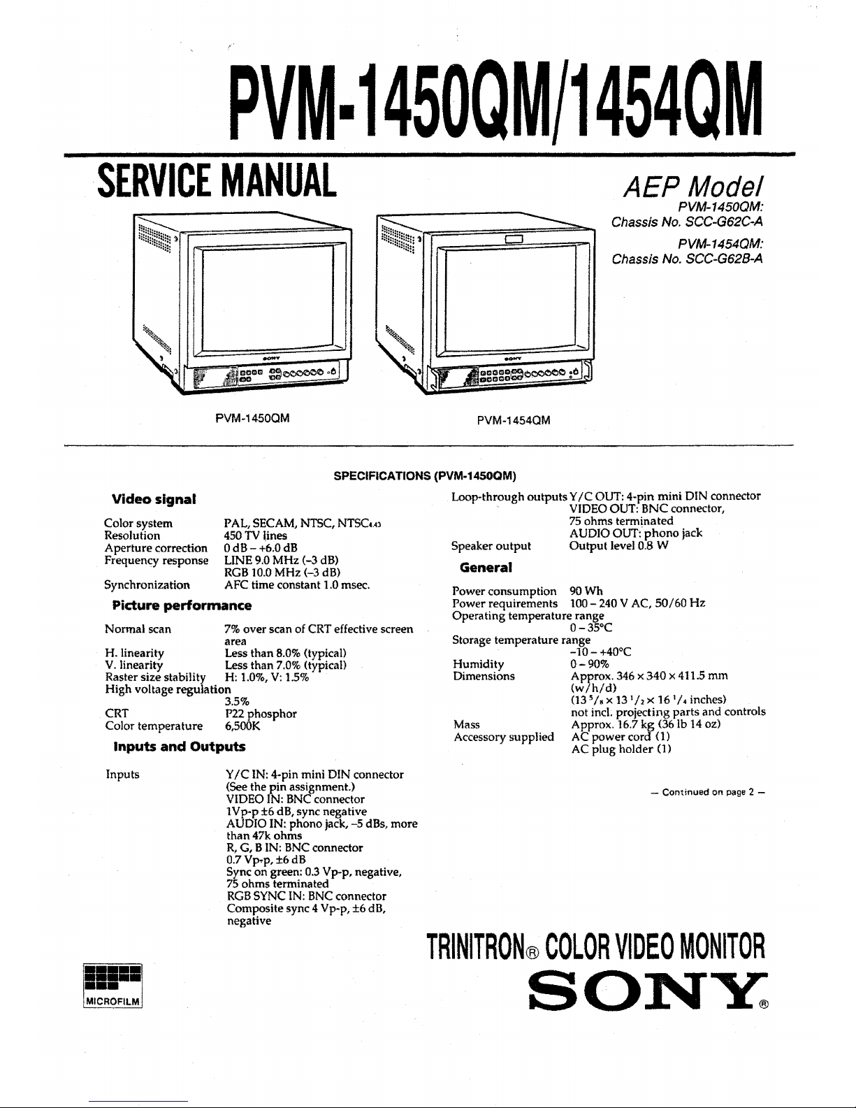
AEP Model
PVM-1450QM:
Chassis No. SCC-G62C-A
D
PVM-1454QM:
Chassis No. SCC-G628-A
PVM-1450QM
PVM-1454QM
SPECIFICATIONS (PVM-1450QM)
Video signal
Color system
Resolution
Aperture correction
Frequency response
PAL, SECAM, NTSC, NTSCw
450TV lines
0dB-+6.0dB
LINE 9.0 MHz (-3 dB)
RGB 10.0 MHz (-3 dB)
Synchronization AFC time constant 1.0 msec.
Pidure performance
Normal scan 7% over scan of CRT effective screen
area
H. linearity Less than 8.0% (typical)
V. linearity Less than 7.0% (typical)
Raster size stability H: 1.0%, V: 1.5%
High voltage regulation
3.5%
CRT P22 phosphor
Color temperature 6,SOOK
Inputs and Outputs
Inputs
Y IC IN: 4-pin mini DIN connector
(See the pin assignment.)
VIDEO IN: BNC connector
1Vp-p ±6 dB, sync negative
AUDIO IN: phono jack, -5 dBs, more
than 47k ohms
R, G, BIN: BNC connector
0.7 Vp,p, ±6 dB
Sync on green: 0.3 Vp-p, negative,
75 ohms terminated
RGB SYNC IN: BNC connector
Composite sync 4 Vp-p, ±6 dB,
negative
Loop-through outputs Y /C OUT: 4-pin mini DIN connector
VIDEO OUT: BNC connector,
75 ohms terminated
AUDIO OUT: phono jack
Speaker output Output level 0.8 W
General
Power consumption 90 Wh
Power requirements 100- 240 V AC, 50/60 Hz
Operating temperature range
0-35°C
Storage temperature range
-10-+40°C
Humidity 0 - 90%
Dimensions Approx. 346 x 340 x 411.5 mm
(w/h/d)
(13
5
/s x 131h x 16 ¼ inches)
not incl. projecting parts and controls
Mass Approx. 16.7 kg (36 lb 14 oz)
Accessory supplied AC power cord (1)
AC plug holder (1)
- Continued on page 2 -
TRINITRON@ COLOR VIDEO MONITOR
SO:NY:
PVM-1450QM/1454QM
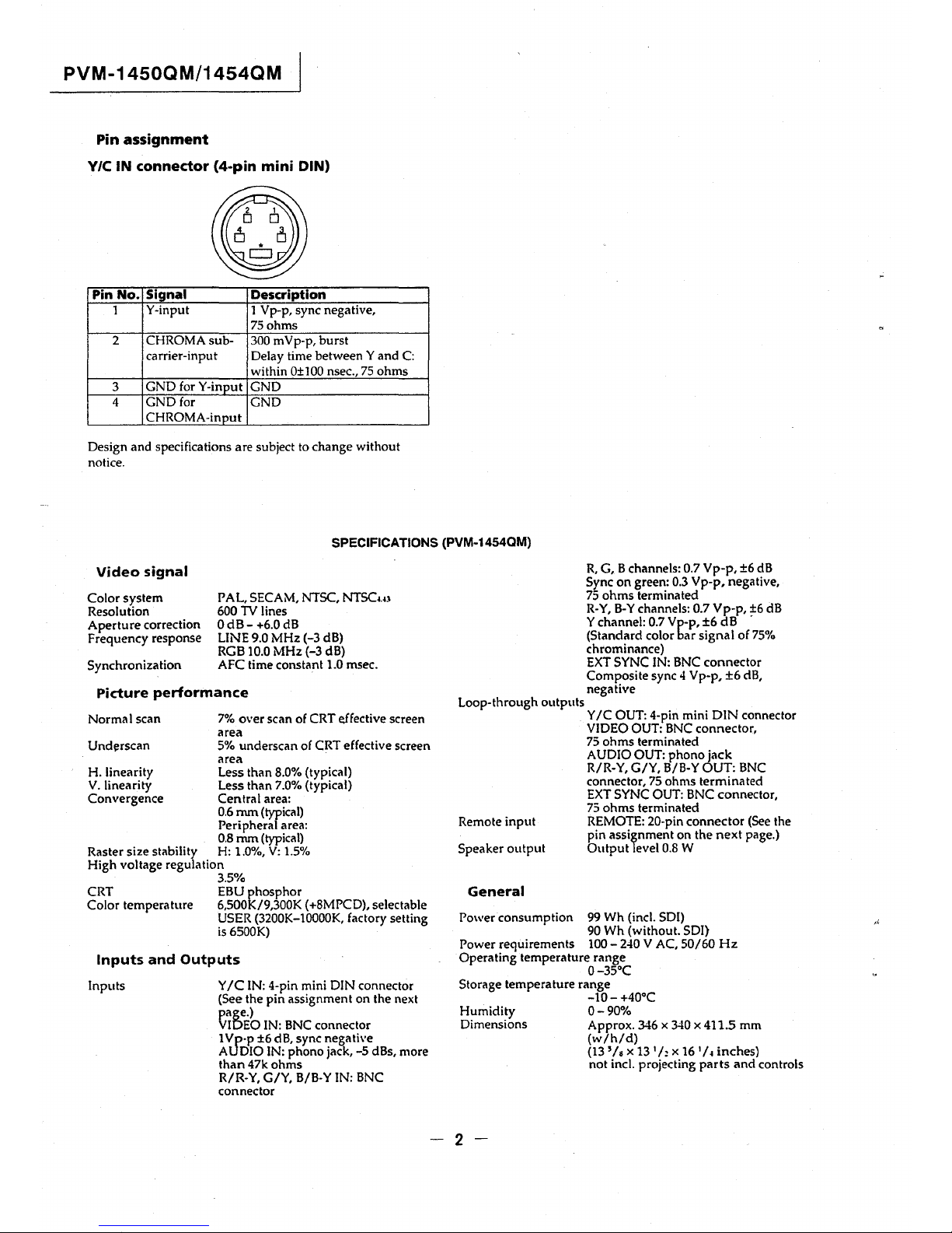
Pin assignment
V/C IN connector (4-pin mini DIN)
Pin No. Signal Description
1
Y-input 1 Vp-p, sync negative,
75 ohms
2 CHROMA sub- 300 mVp-p, burst
carrier-input Delay time between Y and C:
within 0+100 nsec., 75 ohms
3
GND for Y-inout
GND
4
GND for
GND
CHROMA-in out
Design and specifications are subject to change without
notice.
SPECIFICATIONS (PVM-1454QM)
Video signal
Color system
Resolution
Aperture correction
Frequency response
Synchronization
PAL, SECAM, NTSC, NTSCw
600 TV lines
OdB-+6.0dB
LINE 9.0 MHz (-3 dB)
RGB 10.0 MHz (-3 dB)
AFC time constant 1.0 msec.
Picture performance
7% over scan of CRT effective screen
area
Loop-through outputs
R, G, B channels: 0.7 Vp-p, ±6 dB
Sync on green: 0.3 Vp-p, negative,
75 ohms terminated
R-Y, B-Y channels: 0.7 Vp-p, ~6 dB
Y channel: 0.7 Vp-p, ±6 dB
(Standard color bar signal of 75%
chrominance)
EXT SYNC IN: BNC connector
Composite sync 4 Vp-p, ±6 dB,
negative
Y IC OUT: 4-pin mini DIN connector
VIDEO OUT: BNC connector,
Normal scan
Und!!rscan
5% underscan of CRT effective screen
75 ohms terminated
AUDIO OUT: phono jack
H. linearity
V. linearity
Convergence
area
Less than 8.0% (typical)
Less than 7.0% (typical)
Central area:
0.6 mm (typical)
Peripheraf area:
0.8 mm (typical)
Raster size stability H: 1.0%, V: 1.5%
High voltage regulation
CRT
Color temperature
3.5%
EBU phosphor
6,500K/9,300K (+8MPCD), selectable
USER (3200K-10000K, factory setting
is 6500K)
Inputs and Outputs
Inputs Y IC IN: 4-pin mini DIN connector
(See the pin assignment on the next
page.)
VIDEO IN: BNC connector
1 Vp·p ±6 dB, sync negative
AUDIO IN: phono jack, -5 dBs, more
than 47k ohms
R/R-Y, G/Y, B/B-Y IN: BNC
connector
R/R-Y, G/Y, B/B-Y OUT: BNC
connector, 75 ohms terminated
EXT SYNC OUT: BNC connector,
75 ohms terminated
Remote input REMOTE: 20-pin connector (See the
pin assignment on the next page.)
Speaker output Output level 0.8 W
General
Power consumption 99 Wh (incl. SDI)
90 Wh (without. SDI)
Power requirements 100- 240 V AC, 50/60 Hz
Operating temperature range
0-35°C
Storage temperature range
-10-+40°C
Humidity O - 90%
Dimensions Approx. 346 x 340 x 411.5 mm
(w/h/d)
(13 '/ • x 13
1
h x 16
1
/
~
inches)
not incl. projecting parts and controls
-2-
Mass
Approx. 16.7 kg (36 lb 14 oz)
PVM-2054QM
Accessory supplied
AC power cord (1)
AC plug holder (1)
Tally label (1)
Cable with a 20-pin connector (1)
Pin assignment
Y/C IN connector (4-pin mini DIN)
Pin No. Signal
Description
1
Y-input
l Vp-p, sync negative,
75ohms
2
CHROMA sub- 300 mVp-p, burst
carrier-input
Delay time between Y and C:
within 0±100 nsec., 75 ohms
3
GND for Y-input
GND
4
GND for GND
CHROMA-input
-3-
PVM-1450QM/1454QM
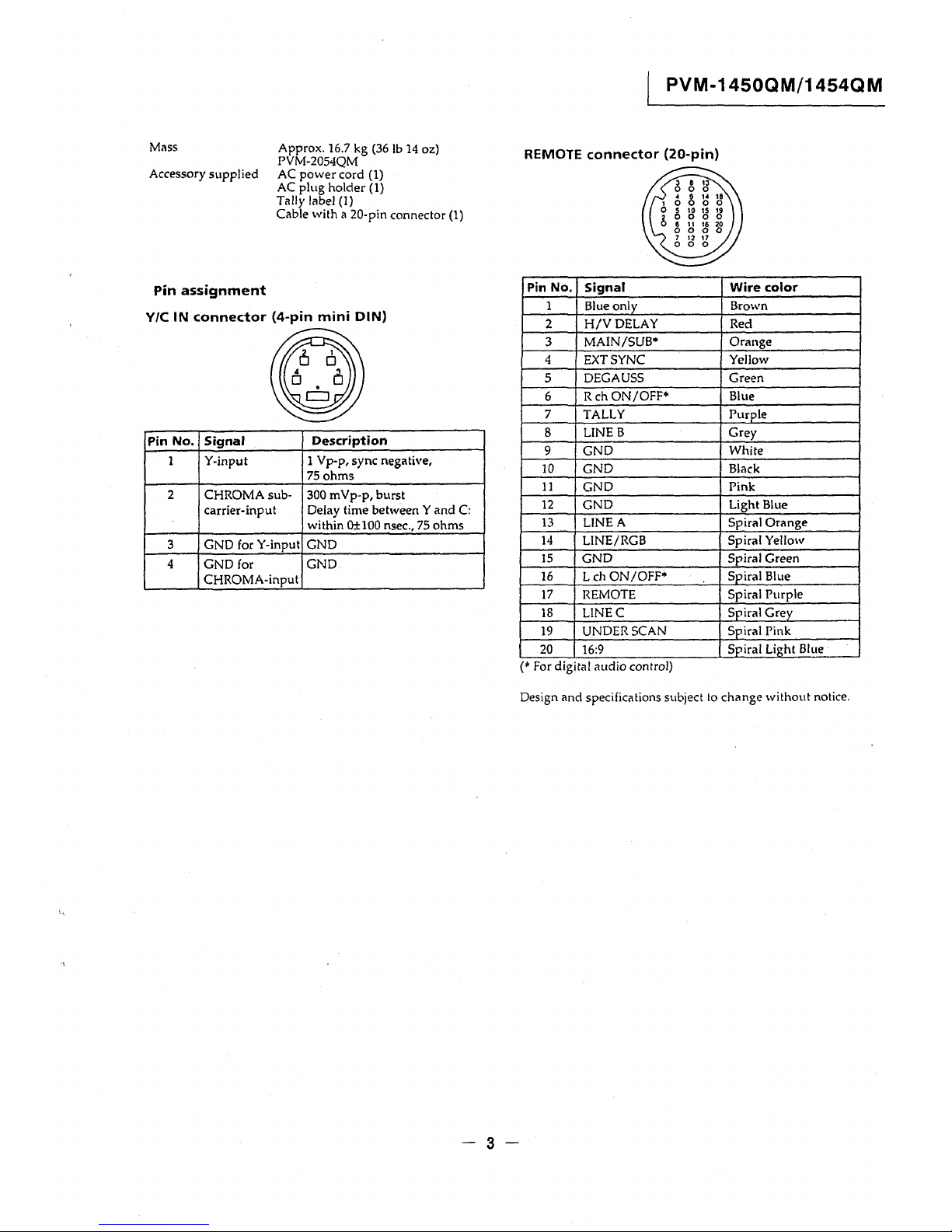
REMOTE connector (20-pin)
Pin No.
Signal
Wire color
1 Blue only Brown
2 H/VDELAY Red
3
MAIN/SUB• Orange
4 EXT SYNC Yellow
5
DEGAUSS Green
6
Reh ON/OFF• Blue
7 TALLY Purple
8
LINE B
Grey
9 GND
White
10 GND
Black
11
GND
Pink
12
GND
Light Blue
13 LINEA Spiral Orange
14 LINE/RGB
Spiral Yellow
15
GND
Spiral Green
16 Leh ON/OFF*
Spiral Blue
17
REMOTE
Spiral Purple
18 LINEC
Spiral Grey
19 UNDER SCAN
Spiral Pink
20 16:9
Spiral Light Blue
(* For digital audio control)
Design and specifications subject to change without notice.
PVM-1450QM/1454QM
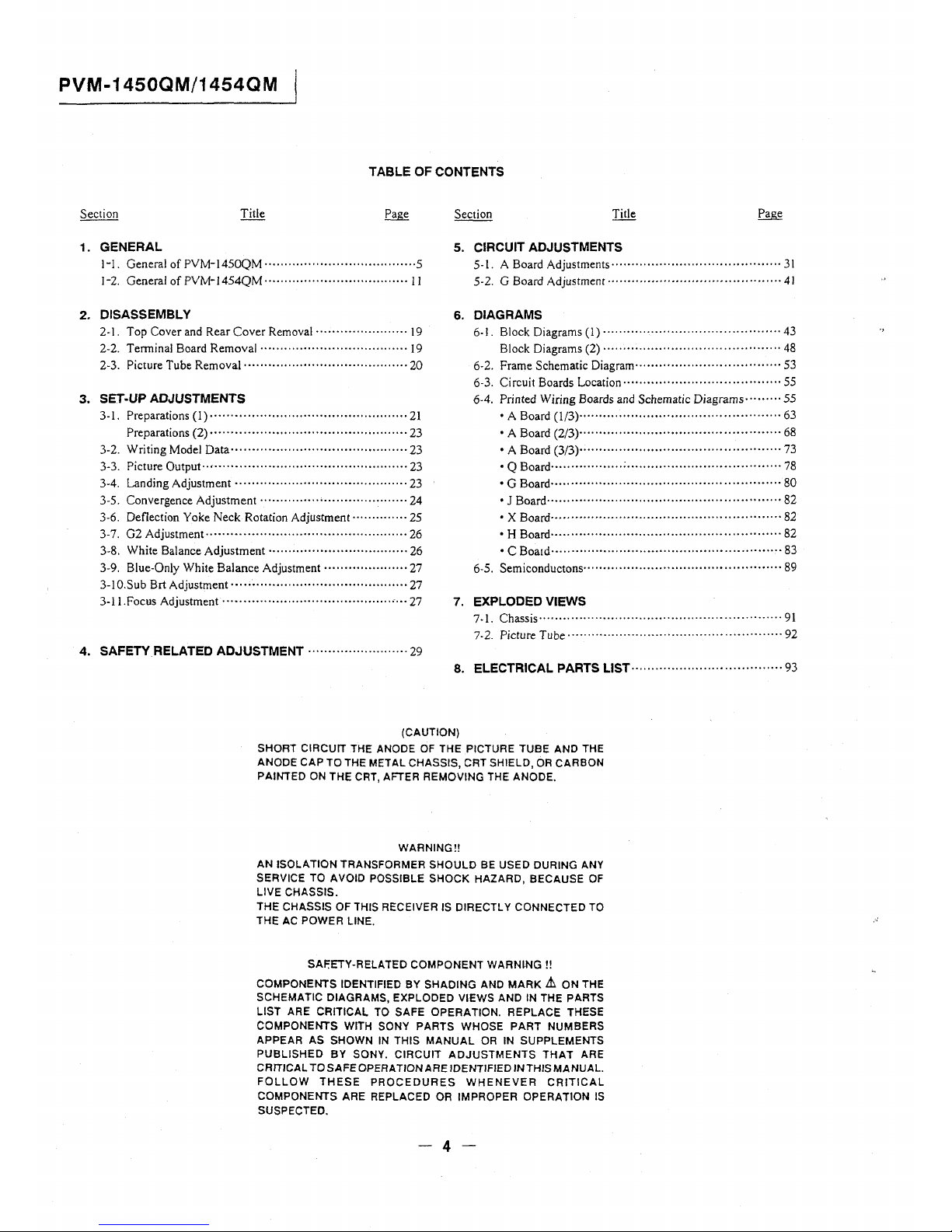
TABLE OF CONTENTS
1. GENERAL 5. CIRCUIT ADJUSTMENTS
1-1. General of PVM-1450QM ...................................... 5
5-1. A Board Adjustments······ .................................... 31
I-2. General of PVM-1454QM · · · · · · · · · · · · · · · · · · · .. · · · · · · · · · · · · · · · l l
5-2. G Board Adjustment ........................................... 41
2. DISASSEMBLY
6. DIAGRAMS
2-I. Top Cover and Rear Cover Removal · · · · · · · · · · · · · · · .. · · · · · · 19
2-2. Terminal Board Removal····································· 19
2-3. Picture Tube Removal········································· 20
6-1. Block Diagrams (1) ............................................ 43
Block Diagrams (2) · ·· · · · · · · ·· ·· ·· .. ··· · · · · · .. · · · · · ·· · · ·· · · · · · · 48
6-2. Frame Schematic Diagram············· ....................... 53
6-3. Circuit Boards Location········· .. ···························· 55
3. SET-UP ADJUSTMENTS
6-4. Printed Wiring Boards and Schematic Diagrams ......... 55
3-1. Preparations (1)····························· .. ··················21
• A Board ( 1/3) ......... · ......... ·· ...... · ... · .... · · ·· .. · · · · .... 63
Preparations (2) · · · · · · · · · · · · · · · · · · · · · · · · · · · ·· ·· .. · · · .. · · · · · · · · · · · 23
3-2. Writing Model Data ............................................ 23
3-3. Picture Output ... , ... ········ .... ······· .. ························ 23
3-4. Landing Adjustment · · · .................. ·· ·· ................. · 23
3-5. Convergence Adjustment .. ···· · · · ...... ·· .................... 24
3-6. Deflection Yoke Neck Rotation Adjustment ........... ··· 25
3-7. G2 Adjustment······"·········································· 26
3-8. White Balance Adjustment ·· · ............ ·· ·· ........ ······ · · 26
3-9. Blue-Only White Balance Adjustment ··· ·· · ·········· ··· · · 27
3-IO.Sub Brt Adjustment · · · · · · · .. · · · · · · · · · ·· · · · · · · · · · · · · · · · · · · · .. · · · 27
• A Board (2/3)--......... · .. · ....................... ·· ·· ........ 68
• A Board (3/3) .................................................. 73
• Q Board .................. ; ...................................... 78
• G Board ......................................................... 80
• J Board .......................................................... 82
• X Board ......................................................... 82
• H Board····· .. ·· .. ·· .... ····· .. ·· .... · .... ····· .. · .... · · .... · · · · 82
• C Boa1d······· .................................................. 83
6-5. Semiconductons .. · .. · · · · · · · · · ·· · · · · · · · · · · · · · · · · · · · · · · · · · · · · · ·· · · 89
3-1 I.Focus Adjustment ........................................... , ... 27
7. EXPLODED VIEWS
7-1. Chassis ............................................................ 91
7-2. Picture Tube····················································· 92
4. SAFETY RELATED ADJUSTMENT ..... ·· .... ···· · · · ·· · · · · · 29
8. ELECTRICAL PARTS LIST····································· 93
(CAUTION)
SHORT CIRCUIT THE ANODE OF THE PICTURE TUBE AND THE
ANODE CAP TO THE METAL CHASSIS, CRT SHIELD, OR CARBON
PAINTED ON THE CRT, AFTER REMOVING THE ANODE.
WARNING!!
AN ISOLATION TRANSFORMER SHOULD BE USED DURING ANY
SERVICE TO AVOID POSSIBLE SHOCK HAZARD, BECAUSE OF
LIVE CHASSIS.
THE CHASSIS OF THIS RECEIVER IS DIRECTLY CONNECTED TO
THE AC POWER LINE.
SAF.ETY-RELATED COMPONENT WARNING!!
COMPONENTS IDENTIFIED BY SHADING AND MARK Lt ON THE
SCHEMATIC DIAGRAMS, EXPLODED VIEWS AND IN THE PARTS
LIST ARE CRITICAL TO SAFE OPERATION. REPLACE THESE
COMPONENTS WITH SONY PARTS WHOSE PART NUMBERS
APPEAR AS SHOWN IN THIS MANUAL OR IN SUPPLEMENTS
PUBLISHED BY SONY. CIRCUIT ADJUSTMENTS THAT ARE
CRITICAL TO SAFE OPERATION ARE IDENTIFIED INTHIS MANUAL.
FOLLOW THESE PROCEDURES WHENEVER CRITICAL
COMPONENTS ARE REPLACED OR IMPROPER OPERATION IS
SUSPECTED.
-4-
SECTION 1
GENERAL
The operating instructions mentioned here are partial abstracts from
the Operating Instruction Manual. The page numbers of the
Operating Instruction Manual remein as in the manual.
1-1. GENERAL OF PVM-1450QM
Features
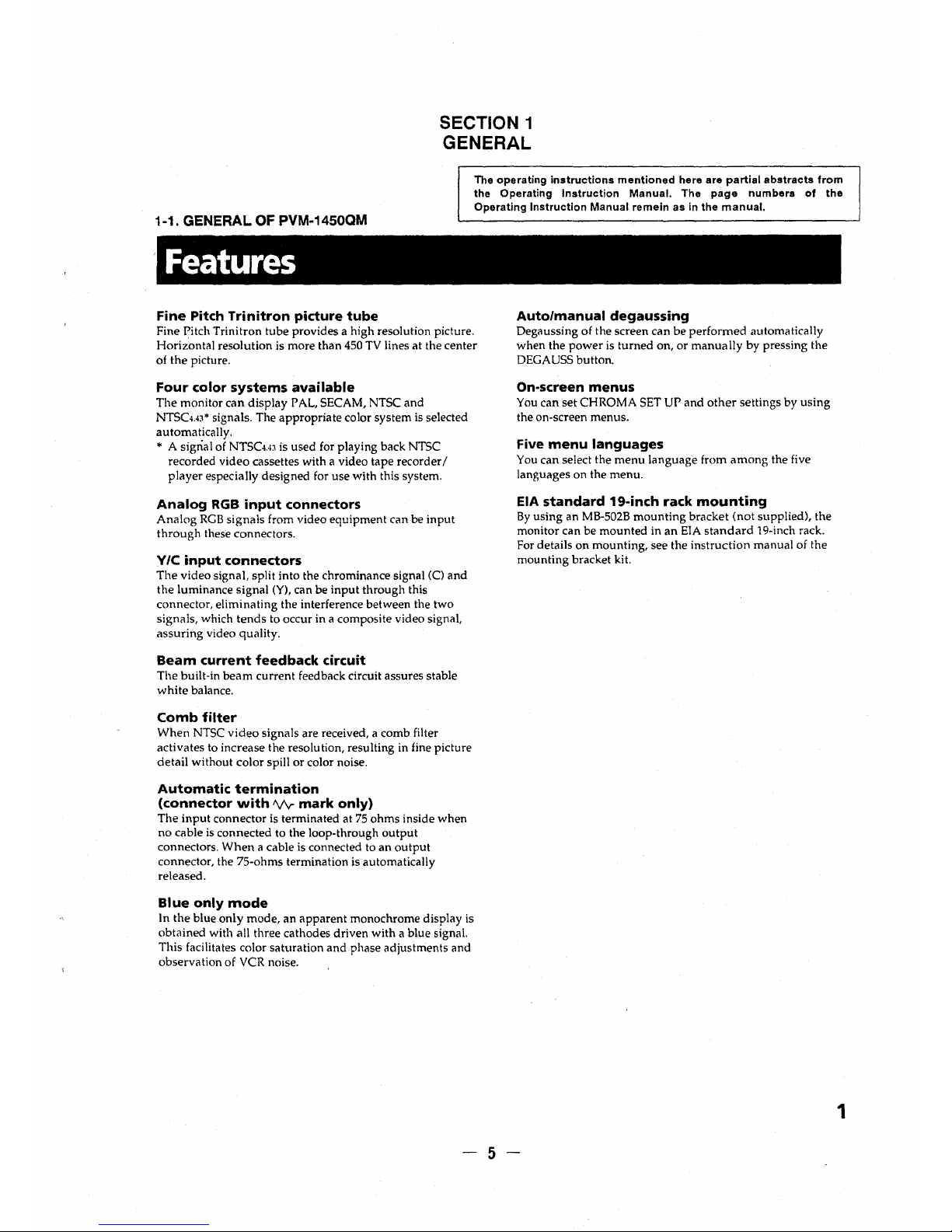
Fine Pitch Trinitron picture tube
Fine Pitch Trinitron tube provides a high resolution picture.
Horizontal resolution is more than 450 TV lines at the center
of the picture.
Four color systems available
The monitor can display PAL, SECAM, NTSC and
NTSCH3* signals. The appropriate color system is selected
automatically.
* A signal of NTSCw is used for playing back NTSC
recorded video cassettes with a video tape recorder/
player especially designed for use with this system.
Analog RGB input connectors
Analog RGB signals from video equipment can be input
through these connectors.
Y/C input connectors
The video signal, split into the chrominance signal (C) and
the luminance signal (Y), can be input through this
connector, eliminating the interference between the two
signals, which tends to occur in a composite video signal,
assuring video quality.
Beam current feedback circuit
The built-in beam current feedback circuit assures stable
white balance.
Comb filter
When NTSC video signals are received, a comb filter
activates to increase the resolution, resulting in fine picture
detail without color spill or color noise.
Automatic termination
(connector with 1\/v-mark only)
The input connector is terminated at 75 ohms inside when
no cable is connected to the loop-through output
connectors. When a cable is connected to an output
connector, the 75-ohms termination is automatically
released.
Blue only mode
In the blue only mode, an apparent monochrome display is
obtained with all three cathodes driven with a blue signal.
This facilitates color saturation and phase adjustments and
observation of VCR noise.
Auto/manual degaussing
Degaussing of the screen can be performed automatically
when the power is turned on, or manually by pressing the
DEGAUSS button.
On-screen menus
You can set CHROMA SET UP and other settings by using
the on-screen menus.
Five menu languages
You can select the menu language from among the five
languages on the menu.
EIA standard 19-inch rack mounting
By using an MB-502B mounting bracket (not supplied), the
monitor can be mounted in an EIA standard 19-inch rack.
For details on mounting, see the instruction manual of the
mounting bracket kit.
-5-
1
Location and function of parts and controls
Front panel
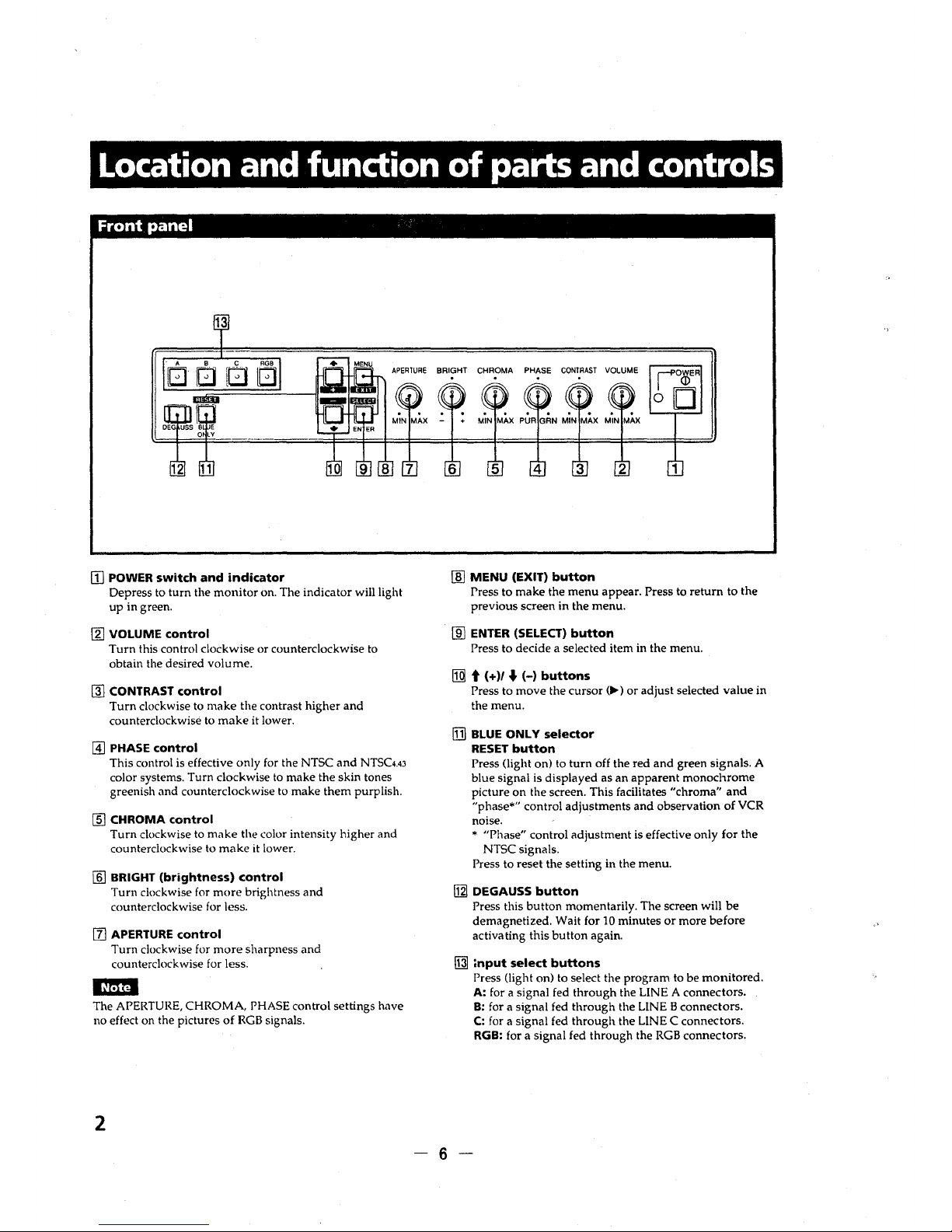
[I] POWER switch and indicator
Depress to turn the monitor on. The indicator will light
up in green.
(g] VOLUME control
Turn this control clockwise or counterclockwise to
obtain the desired volume.
m) CONTRAST control
Turn clockwise to make the contrast higher and
counterclockwise to make it lower.
@] PHASE control
This control is effective only for the NTSC and NTSC4.43
color systems. Turn clockwise to make the skin tones
greenish and counterclockwise to make them purplish.
(ID CHROMA control
Turn clockwise to make the color intensity higher and
counterclockwise to make it lower.
[ID BRIGHT (brightness) control
Turn clockwise for more brightness and
counterclockwise for less.
[I] APERTURE control
Turn clockwise for more sharpness and
counterclockwise for less.
l~Mtl
The APERTURE, CHROMA, PHASE control settings have
no effect on the pictures of RGB signals.
2
BRIGHT CHROMA PHASE CONTRAST VOLUME
1
[ID MENU (EXIT) button
Press to make the menu appear. Press to return to the
previous screen in the menu.
[ID ENTER (SELECT) button
Press to decide a selected item in the menu.
[IQl t ( + )/ .J (-) buttons
Press to move the cursor (Iii-) or adjust selected value in
the menu.
[DJ BLUE ONLY selector
RESET button
Press (light on) to turn off the red and green signals. A
blue signal is displayed as an apparent monochrome
picture on the screen. This facilitates "chroma" and
"phase*" control adjustments and observation of VCR
noise.
* "Phase" control adjustment is effective only for the
NTSC signals.
Press to reset the setting in the menu.
[gj DEGAUSS button
Press this button momentarily. The screen will be
demagnetized. Wait for 10 minutes or more before
activating this button again.
~
,nput select buttons
Press (light on) to select the program to be monitored.
A: for a signal fed through the LINE A connectors.
-6-
B: for a signal fed through the LINE B connectors.
C: for a signal fed through the LINE C connectors.
RGB: for a signal fed through the RGB connectors.
Rear panel
1
2
LINE A
LINE B
'v p.
CIN
VIDEO
VIDEO
~
D .fl
IN
OUT
IN OUT
e:
~
~
~~
AUDIO
AUDIO
IN OUT
IN OUT
@) ©) ©)
@)
ll@LI,
IN
IN
I~
~
R G
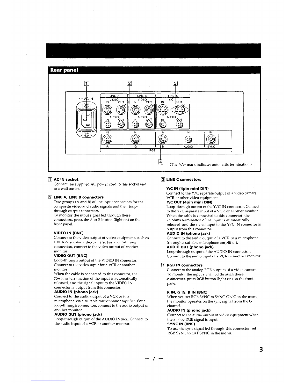
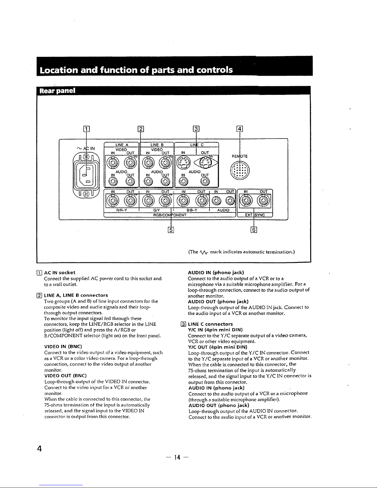
[I] AC IN socket
Connect the supplied AC power cord to this socket and
to a wall outlet.
[g) LINE A, LINE B connectors
Two groups (A and B) of line input connectors for the
composite video and audio signals and their loopthrough output connectors.
To monitor the input signal fed through these
connectors, press the A or B button (light on) on the
front panel.
VIDEO IN (BNC)
Connect to the video output of video equipment, such as
a VCR or a color video camera. For a loop-through
connection, connect to the video output of another
monitor.
VIDEO OUT (BNC)
Loop-through output of the VIDEO IN connector.
Connect to the video input for a VCR or another
monitor.
When the cable is connected to this connector, the
75-ohms termination of the input is automatically
released, and the signal input to the VIDEO IN
connector is output from this connector.
AUDIO IN (phono jack)
Connect to the audio output of a VCR or to a
microphone via a suitable microphone amplifier. For a
loop-through connection, connect to the audio output of
another monitor.
AUDIO OUT (phono jack)
Loop-through output of the AUDIO IN jack. Connect to
the audio input of a VCR or another monitor.
RGB
3
LINE C
YIC
IN OUT
@<@>
.- .- r ,..
,... ,...
AUDIO
IN OUT
©) @
IN
IN IN
~
©>
~I
B AUDIO SYNC
4
(The 'V\r mark indicates autom;it1c termination.)
~
LINE C connectors
VIC IN (4pin mini DIN)
Connect to the Y JC separate output of a video camera,
VCR or other video equipment.
VIC OUT (4pin mini DIN)
Loop-through output of the Y JC IN connector. Connect
to the Y JC separate input of ii VCR or another monitor.
When the cable is connected to this connector the
75-ohms termination of the input is ilUtomatirnlly
released, and the signal input to the Y JC IN connector is
output from this connector.
AUDIO IN (phono jack)
Connect to the audio output of ct VCR or a microphone
(through ii-suitable microphone mnplifier).
AUDIO OUT (phono jack)
Loop-through output of the AUDIO IN connector.
Connect to the audio input of a VCR or another monitor.
@] RGB IN connectors
Connect to the analog RGB outputs of a video camera.
To monitor the input signal fed through these
connectors, press RGB button (light on) nn the front
panel.
R IN, G IN, B IN (BNC)
When you set RGB SYNC to SYNC ONG in the menu,
the monitor operates on the sync signal from the G
channel.
AUDIO IN (phono jack)
Connect to the audio output of video equipment when
the anil!og RGB signal is input.
SYNC IN (BNC)
To use the sync signal fed through this connector, set
RGB SYNC to EXT SYNC in the menu.
3
-7-
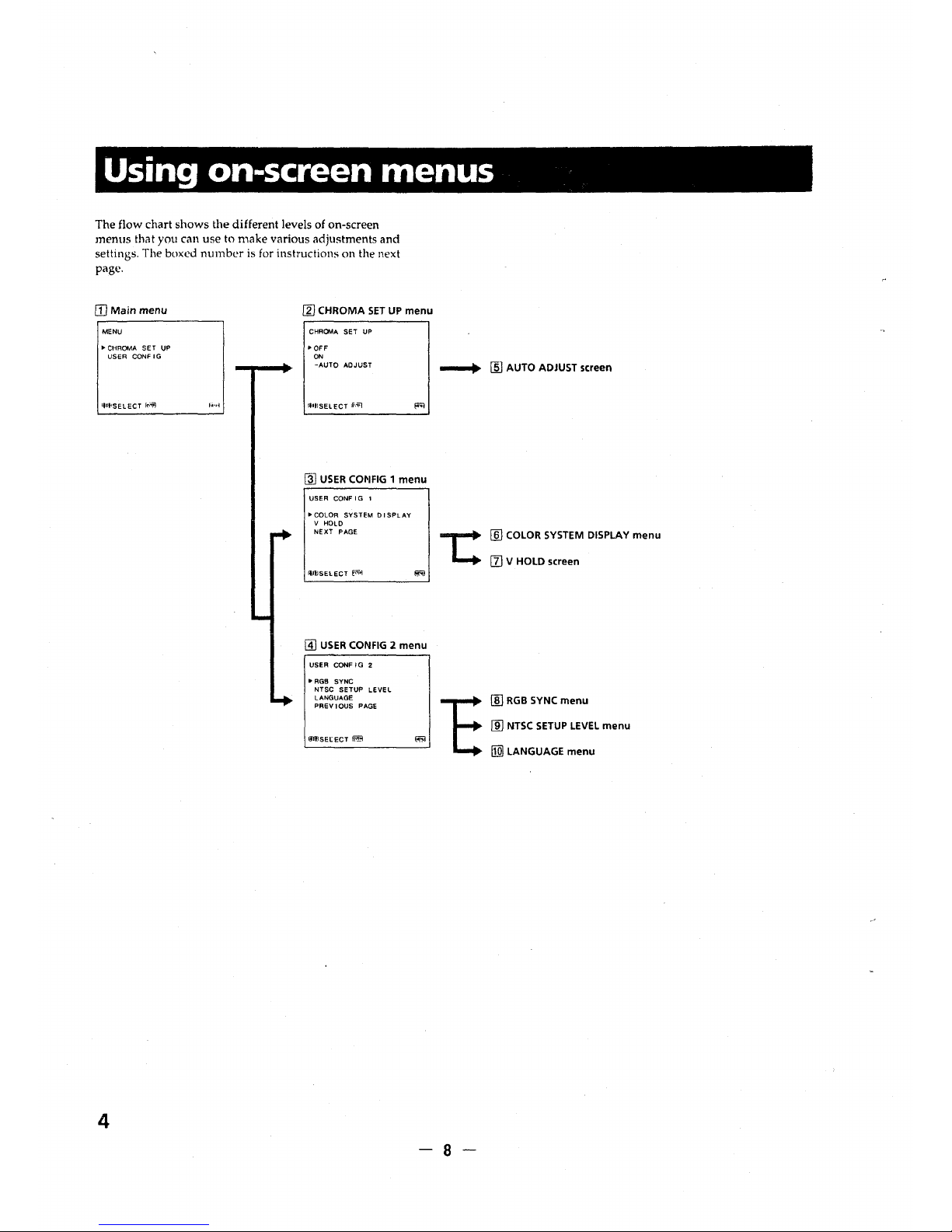
Using on-screen menus
The flow chart shows the different levels of on-screen
menus that you can use to make various adjustments and
settings. The boxed number is for instructions on the next
page.
[D Main menu
MENU
.. CHROMA SET UP
USER CONFIG
lflf
1
SELECT [r."iii)
4
[gJ CHROMA SET UP menu
CHROMA SET UP
•OFF
ON
-AUTO ADJUST
lflflSELECT ii"...,.;i
[ID USER COMFIG 1 menu
USER CONF I G 1
"'COLOR SYSTEM O I SPLAY
V HOLD
NEXT PAGE
flWSELECT [-,iol
@] USER CONFIG 2 menu
USER CONF I G 2
• RGB SYNC
NTSC SETUP LEVEL
LANGUAGE
PREVIOUS PAGE
IJJfJSEl:ECT
~
_.,. [fil AUTO ADJUST screen
,:
[ID COLOR SYSTEM DISPLAY menu
[I] V HOLD screen
!ID RGB SYNC menu
[ID NTSC SETUP LEVEL menu
[IQ) LANGUAGE menu
-8-
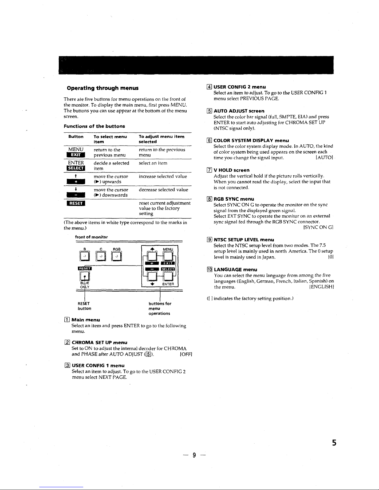
Operating through menus
There are five buttons for menu operations on the front of
the monitor. To display the main menu, first press MENU.
The buttons you can use appear at the bottom of the menu
screen.
Functions of the buttons
Button
To select menu
To adjust menu item
Item selected
MENU
return to the
return to the previous
lli:HII
previous menu
menu
ENTER
decide a selected
select an item
E:~!!!:11
item
t
move the cursor
increase selected value
-
(..,.) upwards
•
move the cursor
decrease selected value
(..,.) downwards
ldi1il
reset current adjustment
value to the factory
setting
(The above items in white type correspond to the marks in
the menu.)
front of monitor
RESET
button
[IJ Main menu
buttons for
menu
operations
Select an item and press ENTER to go to the following
menu.
[g) CHROMA SET UP menu
Set to ON to adjust the internal decoder for CHROMA
and PHASE after AUTO ADJUST([§]). IOFFI
@] USER CONFIG 1 menu
Select an item to adjust. To go to the USER CONFIG 2
menu select NEXT PAGE.
-9-
@] USER CONFIG 2 menu
Select an item to adjust. To go to the USER CONFIG 1
menu select PREVIOUS PAGE.
[§] AUTO ADJUST screen
Select the color bar signal (full, SMPTE, EIA) and press
ENTER to start auto adjusting for CHROMA SET UP
(NTSC signal only).
[ID COLOR SYSTEM DISPLAY menu
Select the color system display mode. In AUTO, the kind
of color system being used appears on the screen each
time you change the signal input. [AUTO[
II] V HOLD screen
Adjust the vertical hold if the picture rolls vertically.
When you cannot read the display, select the input that
is not connected .
[ill RGB SYNC menu
Select SYNC ON G to operate the monitor on the sync
signal from the displayed green signal.
Select EXT SYNC to operate the monitor on an external
sync signal fed through the RGB SYNC connector.
[SYNC ON Gl
[ID NTSC SETUP LEVEL menu
Select the NTSC setup level from two modes. The 7.5
setup level is mainly used in north America. The O setup
level is mainly used in Japan. IOI
[Q] LANGUAGE menu
You can select the menu language from among the five
languages (English, German, French, Italian, Spanish) on
the menu. I ENGLISH I
([ ] indicates the factory setting position.)
5
Power sources
House current
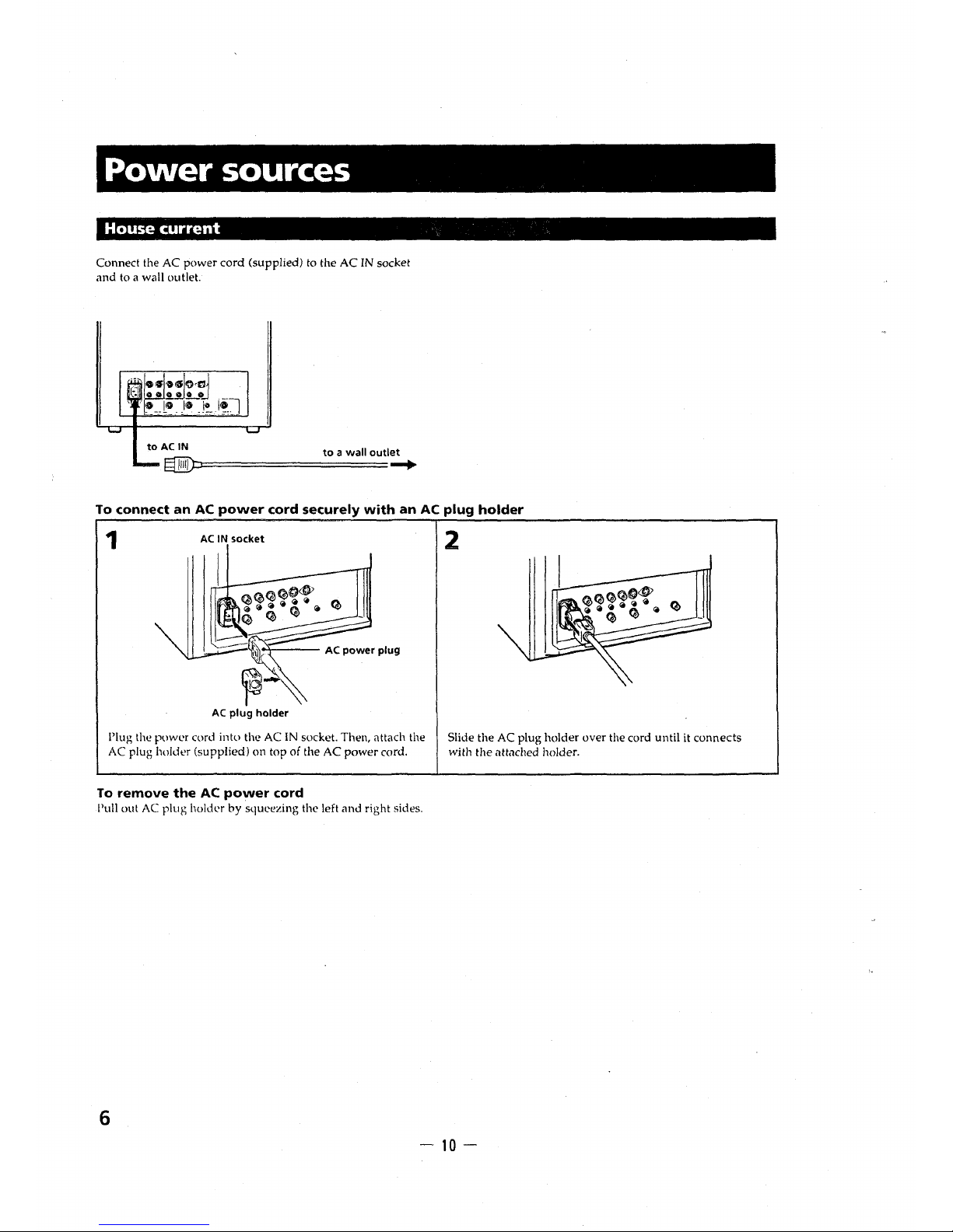
Connect the AC power cord (supplied) to the AC IN socket
and to a wall outlet.
to AC IN to a wall outlet
~i:::========= ...
To connect an AC power cord securely with an AC plug holder
1
AC IN socket
AC plug holder
!'lug the power cord into the AC IN socket. Then, attach the
AC plug holder (supplied) on top of the AC power cord.
To remove the AC power cord
Pull out AC plug hokk•r by squeezing the left and right sides.
6
2
Slide the AC plug holder over the cord until it connects
with the attached holder.
- 10 -

1-2. GENERAL OF PVM-14540M
Features
HR (High Resolution) Trinitron picture tube
HR Trinitron tube provides a high resolution picture ..
Horizontal resolution is more than 600 TV lines at the center
of the picture.
Four color systems available
The monitor can display PAL, SECAM, NTSC and NTSCu)•
signals. The appropriate color system is selected
automatically.
• A signal of NTSCw is used for playing back NTSC
recorded video cassettes with a video tape recorder/
player especially designed for use with this system.
Blue only mode
In the blue only mode, an apparent monochrome display is
obtained with all three cathodes driven with a blue signal.
This facilitates color saturation and phase adjustments and
observation of VCR noise.
Analog RGB/component input connectors
Analog RGB or component (Y, R-Y and B-Y) signals from
video equipment can be input through these connectors.
Y/C input connectors
The video signal, split into the chrominance signal (C) and
the luminance signal (Y), can be input through this
connector, eliminating the interference between the two
signals, which tends to occur in a composite video signal,
assuring video quality.
Beam current feedback circuit
The built-in beam current feedback circuit assures stable
white balance.
Comb filter
When NTSC video signals are received, a comb filter
activates to increase the resolution, resulting in fine picture
detail without color spill or color noise.
Automatic termination
(connector with V'v mark only)
The input connector is terminated at 75 ohms inside when no
cable is co1inected to the loop-through output connectors.
When a cable is connected to an output co1mector, the
75-ohms termination is automatically released.
Underscan mode
The sign.ii normally sc.inned outside of the screen can be
monitored in the undersc.in mode.
,~mrw
When the monitor is in the underscan mode, the dark RGB
scanning lines may appear on th~ top edge of the screen.
These are mused by an internal test signal, rather th.in the
input sign.ii.
Horizontal/vertical delay mode
The horizontal and vertical sync signals can be checked
simultaneously in the H/V delav mode.
External sync input
When the EXT SYNC selector is in the on position, the
monitor can be operated on the sync signal supplied from
an external sync generator.
Auto/manual degaussing
Degaussing of the screen can be performed automatically
when the power is turned on, or manually by pressing the
DEGAUSS button.
On-screen menus
You can set color temperature, CHROMA SET UP, .ind
other settings by using the on-screen menus.
Five menu languages
You can select the menu language from among the five
languages on the menu.
EIA standard 19-inch rack mounting
By using an MB-502B (for PVM-1454QM) or SLR-103 (for
PVM-2054QM) mounting bracket (not supplied), the
monitor can be mounted in an EIA standard 19-inch rack.
For details on mounting, see the instruction manual of the
mounting bracket kit.
SDI (Serial Digital Interface) kit
By using SDI kit, the monitor can display SMPTE 259M 4:2:2
serial digital signal from a digital VTR. (ex. Sony 4:2:2 VTR)
SDI kit: 4:2:2 digital video board
Digital audio board
1
- 11 -
Location and function of parts and controls
Front panel
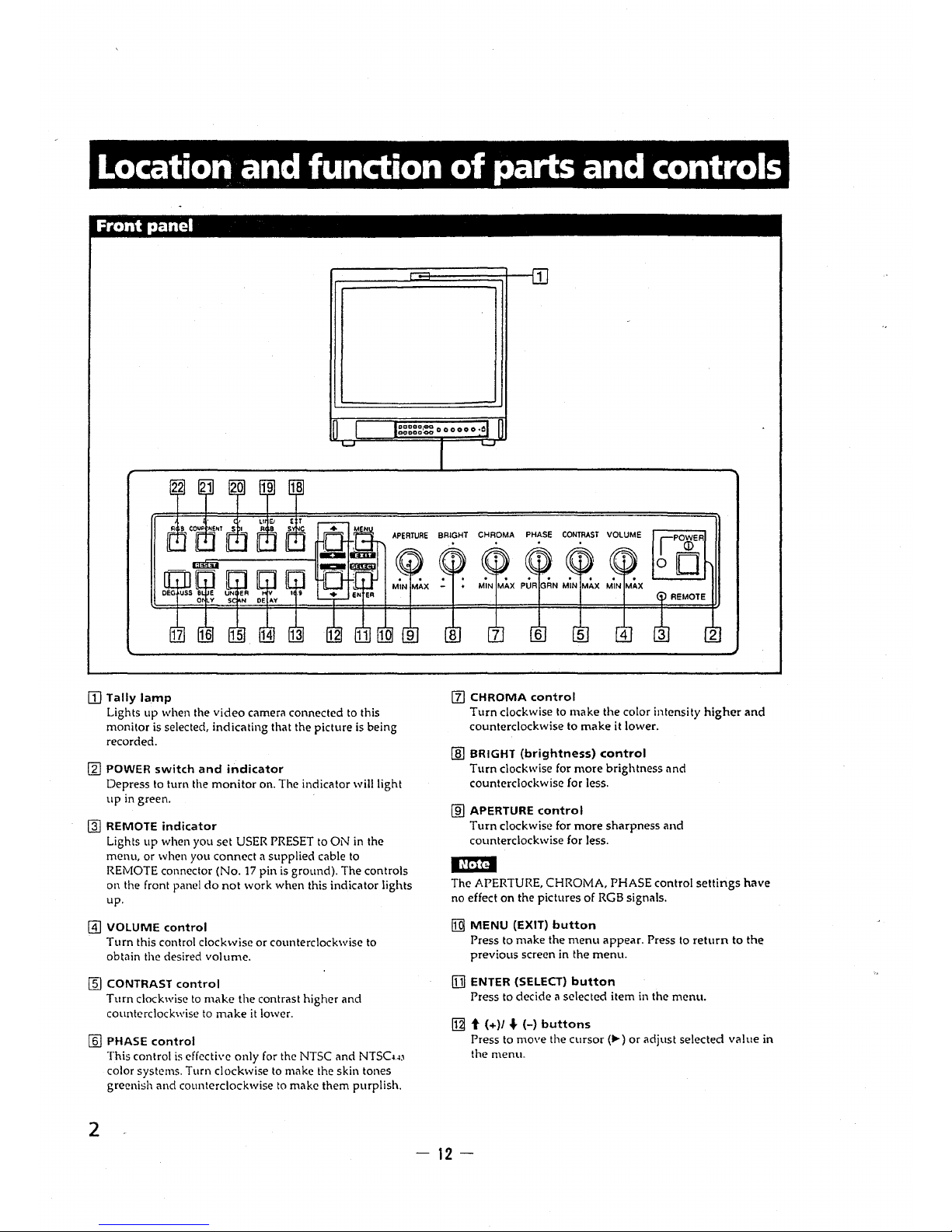
[Il Tally lamp
Lights up when the video camera connected to this
monitor is selected, indicating that the picture is being
recorded.
~
POWER switch and indicator
Depress to tum the monitor on. The indicator will light
up in green.
~
REMOTE indicator
Lights up when you set USER PRESET to ON in the
menu, or when you connect a supplied cable to
REMOTE connector (No. 17 pin is ground). The controls
on the front panel do not work when this indicator lights
up.
@] VOLUME control
Turn this control clockwise or counterclockwise to
obtain the desired volume.
[fil CONTRAST control
Turn clockwise to make the contrast higher and
counterclockwise to make it lower.
[ID PHASE control
2
This control is effective only for the NTSC and NTSCw
color systems. Turn clockwise to make the skin tones
greenish and counterclockwise to make them purplish.
1
[z) CHROMA control
Turn clockwise to make the color intensity higher and
counterclockwise to make it lower.
[ID BRIGHT {brightness) control
Turn clockwise for more brightness and
counterclockwise for less.
(ID APERTURE control
Turn clockwise for more sharpness and
counterclockwise for less.
,~ma
The APERTURE, CHROMA, PHASE control settings have
no effect on the pictures of RGB signals.
[gj MENU {EXIT) button
Press to make the menu appear. Press to return to the
previous screen in the menu.
[11 ENTER {SELECT) button
Press to decide a selected item in the menu.
[gj t (+)/ .f. H buttons
Press to move the cursor(..,.) or adjust selected value in
the menu.
- 12 -
~
16:9 selector
Press (light on) for the signal of 16:9 picture.
~
HN DELAY selector
Press (light on) to observe the horizontal and vertical
sync signals at the same time.
The horizontal sync signal is displayed in the left quarter
of the screen; the ,·ertical sync signal is displayed near
the center of the screen.
[§I UNDER SCAN selector
Press (light on) for underscanning. The display size is
reduced by approximately 5% so that four comers of the
raster are visible.
ff§] BLUE ONLY selector
RESET button
Press (light on) to turn off the red and green signals. A
blue signal is displayed as an apparent monochrome
picture on the screen. This facilitates "chroma" and
"phase*" control adjustments and observation of VCR
noise.
* "Phase" control adjustment is effective only for the
NTSC signals.
Press to reset the setting in the menu.
[Uj DEGAUSS button
Press this button momentarily. The screen will be
demagnetized. Wait for 10 minutes or more before
activating this button again.
[ill EXT SYNC (external sync) selector
Keep this button in the off position (light off) to operate
the monitor on the sync signal from the displayed video
signal.
Keep this button in the on position (light on) to operate
the monitor on an extem11l sync signal fed through the
EXT SYNC connector on the rear panel.
~
LINE/RGB input selector
Select the program to be monitored. Keep this button in
the off position (light off) to feed a signal through the
LINE A, LINE B or LINE C connectors. Keep this button
in the on position (light on) to feed a signal through the
RGB connectors.
~
C/SDI selector
When the LINE/RGB input selector is set to LINE (light
off), press this button (light on) to feed a signal through
the LINE C connectors.
When the LINE/RGB input selector is set to RGB (light
on), press this button (light on) to feed the SD! signal
(optional board is needed).
~
B/COMPONENT selector
When the LINE/RGB input selector is set to LINE (light
off), press this button (light im) to feed a signal through
the LINE B connectors.
When the LINE/RGB input selector is set to RGB (light
on), press this button (light on) to feed the component
signal.
- 13-
~
A/RGB selector
When the LINE/RGB input selector is set to LINE (light
off), press this button (light on) to feed a signal through
the LINE A connectors.
When the LINE/RGB input selector is set to RGB (light
on), press this button (light on) to feed the RGB signal.
3
Location and function of parts and controls
Rear panel
LINE A
LINE B
VIDEO VIDEO
IN OUT IN OUT
AUDIO AUDIO
IN OUT
IN OUT
©) ©) ©) ©)
IN
@
3
LI C
AUDIO
OUT
©)
IN OUT IN OUT IN OUT IN
R/A-Y G/Y BIB-Y
RGBICOM ONENT
5
(The Vv- mark indicates automatic termination.)
II] AC IN socket AUDIO IN (phono jack)
Connect the supplied AC power cord to this socket and
to a wall outlet.
[g] LINE A, LINE B connectors
4
Two groups (A and B) of line input connectors for the
composite video and audio signals and their loop-
through output connectors.
To monitor the input signal fed through these
connectors, keep the LINEIRGB selector in the LINE
position (light off) and press the AIRGB or
BICOMPONENT selector (light on) on the front panel.
VIDEO IN (BNC)
Connect to the video output of a video equipment, such
as a VCR or a color video camera. For a loop-through
connection, connect to the video output of another
monitor.
VIDEO OUT (BNC)
Loop-through output of the VIDEO IN connector.
Connect to the video input for a VCR or another
monitor.
When the cable is connected to this connector, the
75-ohms termination of the input is automatically
released, and the signal input to the VIDEO IN
connector is output from this connector.
Connect to the audio output of a VCR or to a
microphone via a suitable microphone amplifier. For a
loop-through connection, connect to the audio output of
another monitor.
AUDIO OUT (phono jack)
Loop-through output of the AUDIO IN jack. Connect to
the audio input of a VCR or another monitor.
@I LINE C connectors
Y/C IN (4pin mini DIN)
Connect to the Y IC separate output of a video camera,
VCR or other video equipment.
Y/C OUT (4pin mini DIN)
Loop-through output of the Y IC IN connector. Connect
to the Y IC separate input of a VCR or another monitor.
When the cable is connected to this connector, the
75-ohms termination of the input is automatically
released, and the signal input to the Y IC IN connector is
output from this connector.
AUDIO IN (phono jack)
Connect to the audio output of a VCR or a microphone
(through a suitable microphone amplifier).
-14-
AUDIO OUT (phono jack)
Loop-through output of the AUDIO IN connector.
Connect to the audio input of a VCR or another monitor.

@] REMOTE connector (20pin)
Connect to the tally output of a control console, specialeffect generator, etc. The tally lamp on the front panel
will be turned on and off by the connected equipment.
This connector can be used for connecting a remote
controller. For the pin assignment of this connector, see
"Specifications" on page 10.
[§) RGB/COMPONENT connectors
RGB signal or component signal input connectors and
their loop-through output connectors.
To monitor the input signal fed through these
connectors, keep the LINE/RGB selector in the RGB
position (light on), and press the A/RGB or
B/COMPONENT selector (light on) on the front panel.
R/R-Y IN, G/Y IN, B/B-Y IN {BNC)
When the EXT SYNC selector on the front panel is in the
off position (light off), the monitor operates on the sync
signal from the G/Y channel.
To monitor the RGB signal
Connect to the analog RGB signal outputs of a video
camera.
To monitor the component signal
Connect to the R-Y /Y /B-Y component signal outputs of
a Sony Betacam video camera.
R/R-Y OUT, GfY OUT, B/B-Y OUT {BNC)
Loop-through outputs of the R/R-Y IN, G/Y IN, B/B-Y
IN connectors '
For RGB signal
Connect to the analog RGB signal inputs of a video
printer or another monitor.
For component signal
Connect to the R-Y /Y /B-Y component signal inputs of a
Betacam video recorder.
When the cables are connected to these connectors, the
75-ohms termination of the inputs is automatically
released, nnd the signal inputs to the R/R-Y IN, G/Y IN,
B/B-Y IN connectors are output from these connectors.
AUDIO IN (phone jack)
Connect to the audio output of video equipment when
the analog RGB or component signal is input.
AUDIO OUT (phone jack)
Loop-through outputs of the AUDIO IN connector.
[§] EXT SYNC (external sync) connectors
To use the sync signnl fed through this connector, press
the EXT SYNC selector (light on).
IN (BNC)
When this monitor operates-on an external sync signal,
connect the reference signal from a sync generator to this
connector.
OUT (BNC)
Loop-through output of the EXT SYNC IN connector.
Connect to the external sync input of video equipment to
be synchronized with this monitor.
When the cable is connected to this connector, the 75-
ohms termination of the input is released, and the signal
input to the IN connector is output from this connector.
- 15 -
5
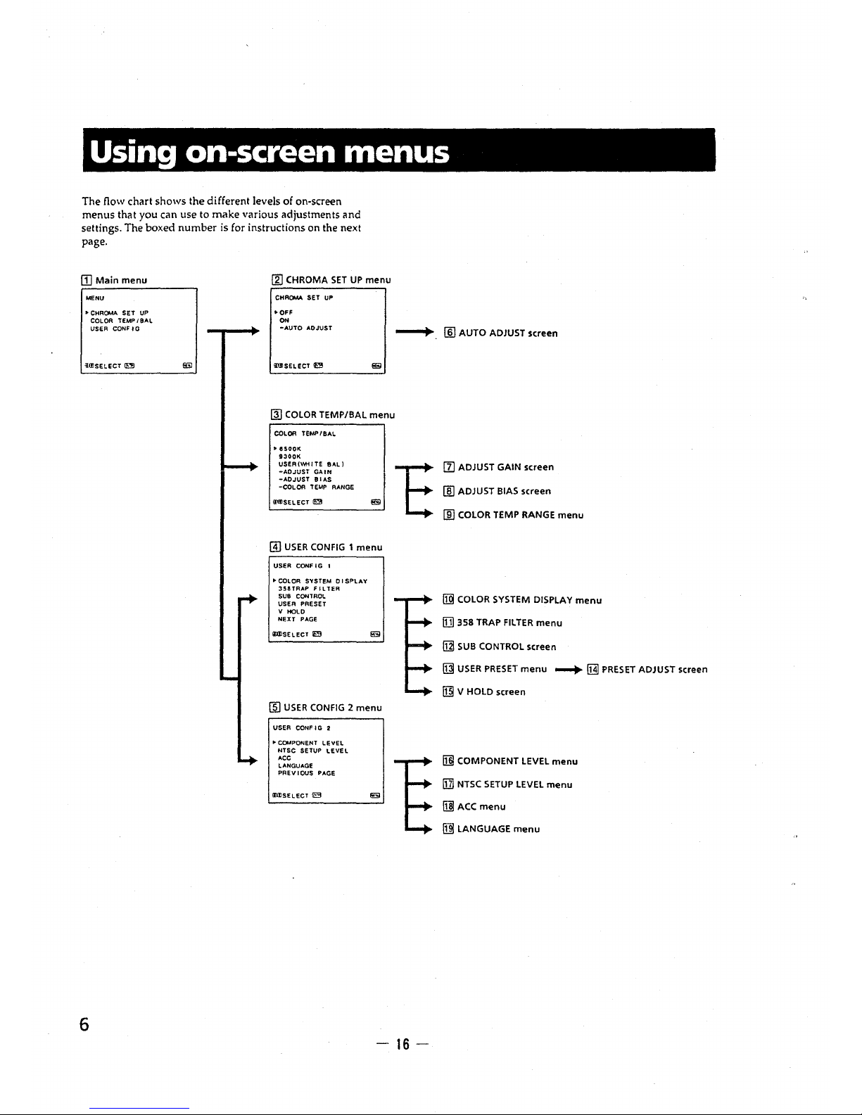
Using on-screen menus
The flow chart shows the different levels of on-screen
menus that you can use to make various adjustments and
settings. The boxed number is for instructions on the next
page.
(I] Main menu
MENU
(2] CHROMA SET UP menu
CHROMA SET UP
•OFF
°"
to CHROMA SET UP
COLOR TEMP/BAL
USER CONF IG
-AUTO ADJUST
~- [ID AUTO ADJUST screen
i(J)SELECT
~
6
msELECT !Ira
~
COLOR TEMP/BAL menu
COLOR TEMP I BAL
,. esoot<.
9300K
USER(.,,.ITE BAL)
-ADJUST GAIN
-AO JUST BI AS
-COL OR TEMP RANGE
111])SELECT IE[l
@) USER CONFIG 1 menu
USER CONF I G 1
• COLOR SYSTEM O I SP'LAY
358TFtAP FILTER
SUB CONTROi.
USER PRESET
V HOLD
NEXT PAGE
lllllSELECT IE;j
(ID USER CONFIG 2 menu
USER CONF I G 2
,. COMPONENT LEVEL
NTSC SETUP LEVEL
ACC
LANGUAGE
PREVIOUS PAGE
IDI'SELECT
~
t
E
-16-
[z) ADJUST GAIN screen
[ID ADJUST BIAS screen
(ID COLOR TEMP RANGE menu
[j] COLOR SYSTEM DISPLAY menu
fl] 358 TRAP FILTER menu
[ill SUB CONTROL screen
~
USER PRESET menu --+ [j]] PRESET ADJUST screen
[i]l V HOLD screen
[i] COMPONENT LEVEL menu
[ii NTSC SETUP LEVEL menu
[i] ACC menu
Ii]] LANGUAGE menu
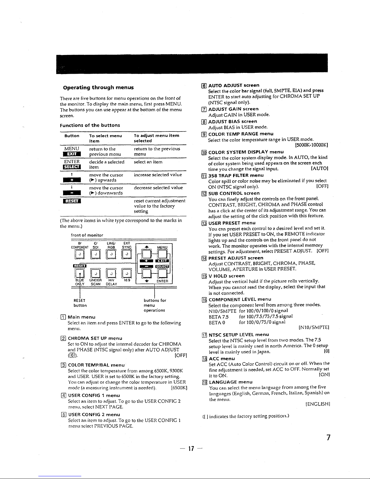
Operating through menus
There are five buttons for menu operations on the front of
the monitor. To display the main menu, first press MENU.
The buttons you can use appear at the bottom of the menu
screen.
Functions of the buttons
Button
To select menu
To adjust menu item
item
selected
MENU
return to the
return to the previous
.:i:li•
previous menu
menu
ENTER
decide a selected
select an item
lja!~:51
item
move the cursor
increase selected value
--
(.,..) upwards
move the cursor
decrease selected value
(.,..) downwards
ligilll
reset current adjustment
value to the factory
setting
(The above items in white type correspond to the marks in
the menu.)
front of monitor
Bl Ci LINE/ EXT
COMPONENT SDI AGB SYNC
D D G [CJ
..
w D Q D
BL E UNDER HIV 16:9
0 LY SCAN DELAY
RESET
button
[Il Main menu
buttons for
menu
operations
Select an item and press ENTER to go to the folio.wing
menu.
~
CHROMA SET UP menu
Set to ON to adjust the internal decoder for CHROMA
and PHASE (NTSC signal only) after AUTO ADJUST
(ffi]). (OFF)
@) COLOR TEMP/BAL menu
Select the color temperature from among 6500K, 9300K
and USER. USER is set to 6500K in the factory setting.
You can adjust or change the color temperature in USER
mode (a measuring instrument is needed). (6500K)
@] USER CONFIG 1 menu
Select an item to adjust. To go to the USER CONFIG 2
menu, select NEXT I' AGE.
ffi) USER CONFIG 2 menu
Select an item to adjust. To go to the USER CONr-IG 1
menu select PREVIOUS PAGE.
[ID AUTO ADJUST screen
Select the color bar signal (full, SMPTE, EIA) and press
ENTER to start auto adjusting for CHROMA SET UP
(NTSC signal only).
(l] ADJUST GAIN screen
Adjust GAIN in USER mode.
(ID ADJUST BIAS screen
Adjust BIAS in USER mode.
(ID COLOR TEMP RANGE menu
Select the color temperature range in USER mode.
[S0OOK-lOO00K)
[ill COLOR SYSTEM DISPLAY menu
Select the color system display mode. In AUTO, the kind
of color system being used appears on the screen each
time you change the signal input. (AUTO)
[TI] 358 TRAP Fil TER menu
Color spill or color noise may be eliminated if you select
ON (NTSC signal only). !OFF!
[gj SUB CONTROL screen
You can finely adjust the controls on the front panel.
CONTRAST, BRIGHT, CHROMA and PHASE control
has a click at the center of its adjustment range. You can
adjust the setting of the click position with this feature.
~
USER PRESET menu
You can preset each control to a desired level and set it.
If you set USER PRESET to ON, the REMOTE indicator
lights up and the controls on the front panel do not
work. The monitor operates with the internal memory
settings. For adjustment, select PRESET ADJUST. [OFF!
~
PRESET ADJUST screen
Adjust CONTRAST, BRIGHT, CHROMA, PHASE,
VOLUME, APERTURE in USER PRESET.
[ill V HOLD screen
Adjust the vertical hold if the picture rolls vertically.
When you cannot read the display, select the input that
is not connected.
[j]] COMPONENT LEVEL menu
Select the component level from among three modes.
N10/SMPTE for 100/0/100/0 sign.ii
BETA 7.5 for 100/7.5/75/7.5 signal
BET AO for 100/0/75/0 signal
[N10/SMPTEI
[TI] NTSC SETUP LEVEL menu
Select the NTSC setup level from two modes. The 7.5
setup level is mainly used in north America. The 0 setup
level is mainly used in Japan. [OJ
5]I ACC menu
Set ACC (Auto Color Control) circuit on or off. When the
fine adjustment is needed, set ACC to OFF. Normally set
it to ON. [ONI
~
LANGUAGE menu
You can select the menu language from among the five
languages (English, German, French, Italian, Spanish) on
the menu.
[ENGLISH!
(I I indicates the foctory setting position.)
7
- 17 -
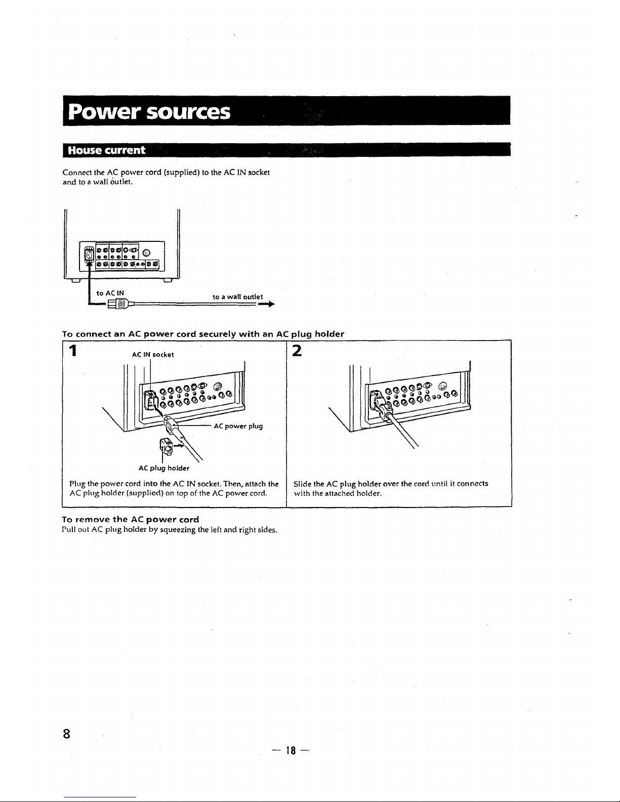
Power sources
House current
Connect the AC power cord (supplied) to the AC IN socket
and to a wall outlet.
to AC IN to a wall outlet
efilD::=========--+-
To connect an AC power cord securely with an AC plug holder
1
AC IN socket
AC plug holder
Plug the power cord into the AC IN socket. Then, attach the
AC plug holder (supplied) on top of the AC power cord.
To remove the AC power cord
Pull out AC plug holder by squeezing the left and right sides.
8
2
Slide the AC plug holder over the cord until it connects
with the attached holder.
- 18 -
SECTION 2
DISASSEMBLY
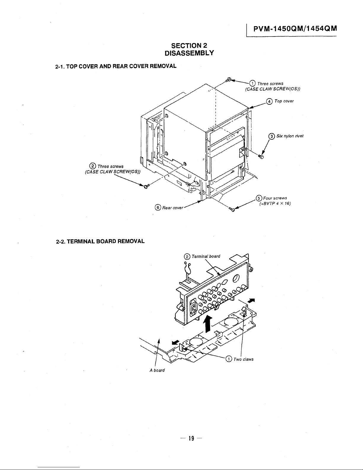
2-1. TOP COVER AND REAR COVER REMOVAL
PVM-1450QM/1454QM
~G) Three screws
.,-- , (CASE CLAW SCREW(OS))
@ Rear cover
2-2. TERMINAL BOARD REMOVAL
A board
- 19-
I
I
© Top cover
PVM-1450QM/1454QM
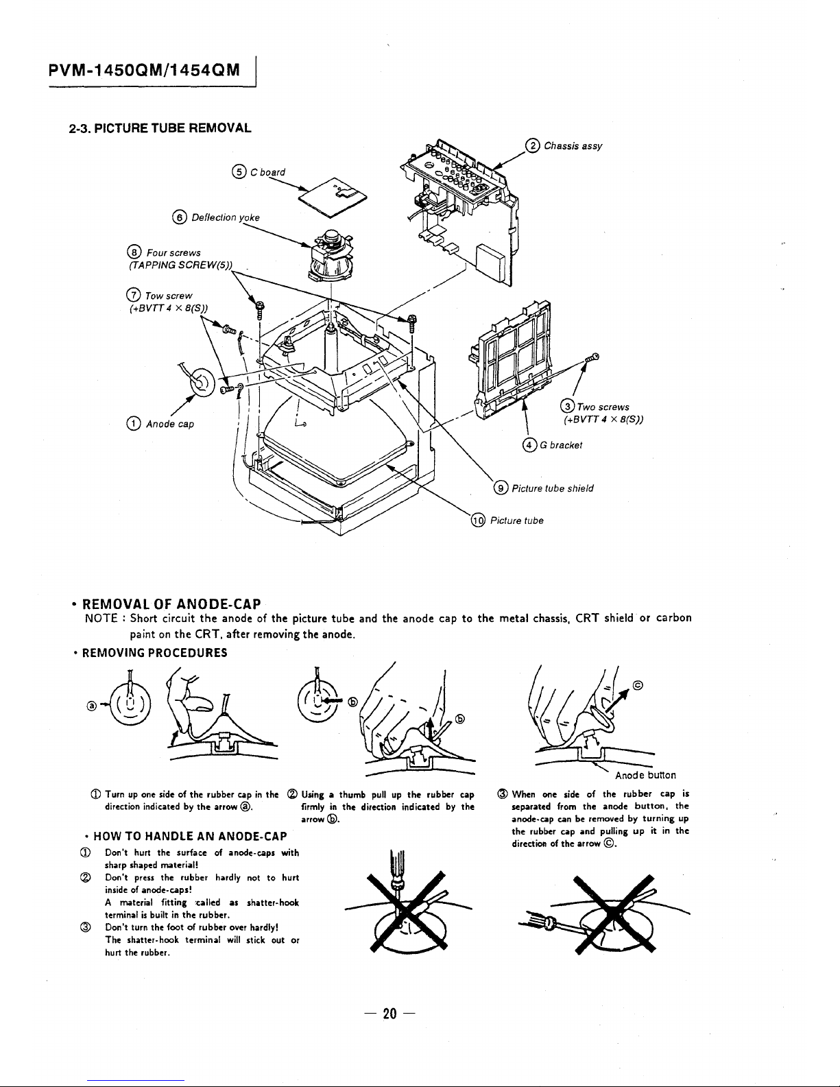
2-3. PICTURE TUBE REMOVAL
@ Cboard
@ Delledfo, yoke
~
@ Four screws
(TAPPING SCREW(5))
(z) Tow screw
(+BVTT 4 X B(S))
•REMOVALOFANOD~CAP
@ Chassis assy
1
@rwoscrews
(+BVTT 4 x B(S))
©G bracket
@ Picture tube shield
NOTE : Short circuit the anode of the picture tube and the anode cap to the metal chassis, CRT shield or carbon
paint on the CRT, after removing the anode.
• REMOVING PROCEDURES
~@
~
CD Turn up one side of the rubber cap in the ® Using a thumb pull up the rubber cap
direction indicated by the arrow@. firmly in the direction indicated by the
arrow@.
• HOW TO HANDLE AN ANODE-CAP
CD Don't hurt the surface of anode-caps with
sharp shaped material!
® Don't press the rubber hardly not to hurt
inside of anode-caps!
A material fitting :called as shatter-hook
terminal is built in the rubber.
@ Don't turn the foot of rubber over hardly!
The shatter-hook terminal will stick out or
hurt the rubber.
- 20 -
@ When one side of the rubber cap is
separated from the anode button, the
anode-cap can be removed by turning up
the rubber cap and pulling up it in the
direction of the arrow ©.
PVM-1450QM/1454QM
SECTION 3
SET-UP ADJUSTMENTS
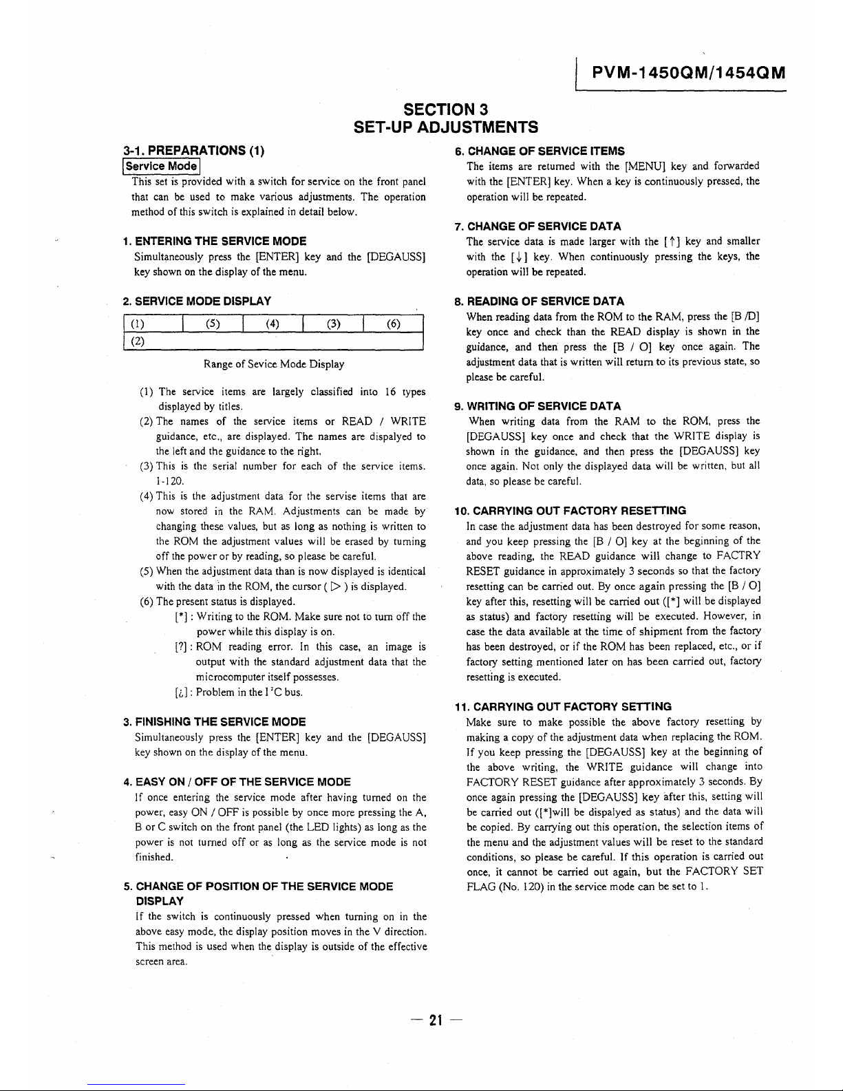
3-1. PREPARATIONS (1)
I Service Mode I
This set is provided with a switch for service on the front panel
that can be used to make various adjustments. The operation
method of this switch is explained in detail below.
1. ENTERING THE SERVICE MODE
Simultaneously press the [ENTER] key and the [DEGAUSS]
key shown on the display of the menu.
2. SERVICE MODE DISPLAY
(I)
(5)
(4)
(3)
(6)
(2)
Range of Sevice Mode Display
(1) The service items are largely classified into 16 types
displayed by titles.
(2) The names of the service items or READ / WRITE
guidance, etc., are displayed. The names are dispalyed to
the left and the guidance to the right.
(3) This is the serial number for each of the service items.
1-120.
( 4) This is the adjustment data for the servise items that are
now stored in the RAM. Adjustments can be made by
changing these values, but as long as nothing is written to
the ROM the adjustment values will be erased by turning
off the power or by reading, so please be careful.
(5) When the adjustment data than is now displayed is identical
with the data in the ROM, the cursor ( I> ) is displayed.
(6) The present status is displayed.
[*] : Writing to the ROM. Make sure not to tum off the
power while this display is on.
[?] : ROM reading error. In this case, an image is
output with the standard adjustment data that the
microcomputer itself possesses.
[i,): Problem in the I 'C bus.
3. FINISHING THE SERVICE MODE
Simultaneously press the [ENTER] key and the [DEGAUSS]
key shown on the display of the menu.
4. EASY ON / OFF OF THE SERVICE MODE
If once entering the service mode after having turned on the
power, easy ON / OFF is possible by once more pressing the A,
B or C switch on the front panel (the LED lights) as long as the
power is not turned off or as long as the service mode is not
finished.
5. CHANGE OF POSITION OF THE SERVICE MODE
DISPLAY
If the switch is continuously pressed when turning on in the
above easy mode, the display position moves in the V direction.
This method is used when the display is outside of the effective
screen area.
6. CHANGE OF SERVICE ITEMS
The items are returned with the [MENU] key and forwarded
with the [ENTER] key. When a key is continuously pressed, the
operation will be repeated.
7. CHANGE OF SERVICE DATA
The service data is made larger with the [ t] key and smaller
with the [ i] key. When continuously pressing the keys, the
operation will be repeated.
8. READING OF SERVICE DATA
When reading data from the ROM to the RAM, press the [B /DJ
key once and check than the READ display is shown in the
guidance, and then press the [B / OJ key once again. The
adjustment data that is written will return to its previous state, so
please be careful.
9. WRITING OF SERVICE DATA
When writing data from the RAM to the ROM, press the
[DEGAUSS] key once and check that the WRITE display is
shown in the guidance, and then press the [DEGAUSS] key
once again. Not only the displayed data will be written, but all
data, so please be careful.
10. CARRYING OUT FACTORY RESETTING
In case the adjustment data has been destroyed for some reason,
and you keep pressing the [B / OJ key at the beginning of the
above reading, the READ guidance will change to FACTRY
RESET guidance in approximately 3 seconds so that the factory
resetting can be carried out. By once again pressing the [B / OJ
key after this, resetting will be carried out ([*] will be displayed
as status) and factory resetting will be executed. However, in
case the data available at the time of shipment from the factory
has been destroyed, or if the ROM has been replaced, etc., or if
factory setting mentioned later on has been carried out, factory
resetting is executed.
11. CARRYING OUT FACTORY SETTING
Make sure to make possible the above factory resetting by
making a copy of the adjustment data when replacing the ROM.
If you keep pressing the [DEGAUSS] key at the beginning of
the above writing, the WRITE guidance will change into
FACTORY RESET guidance after approximately 3 seconds. By
once again pressing the [DEGAUSS] key after this, setting will
be carried out ([*]will be dispalyed as status) and the data will
be copied. By carrying out this operation, the selection items of
the menu and the adjustment values will be reset to the standard
conditions, so please be careful. If this operation is carried out
once, it cannot be carried out again, but the FACTORY SET
FLAG (No. 120) in the service mode can be set to I.
-21-
PVM-1450QM/1454QM
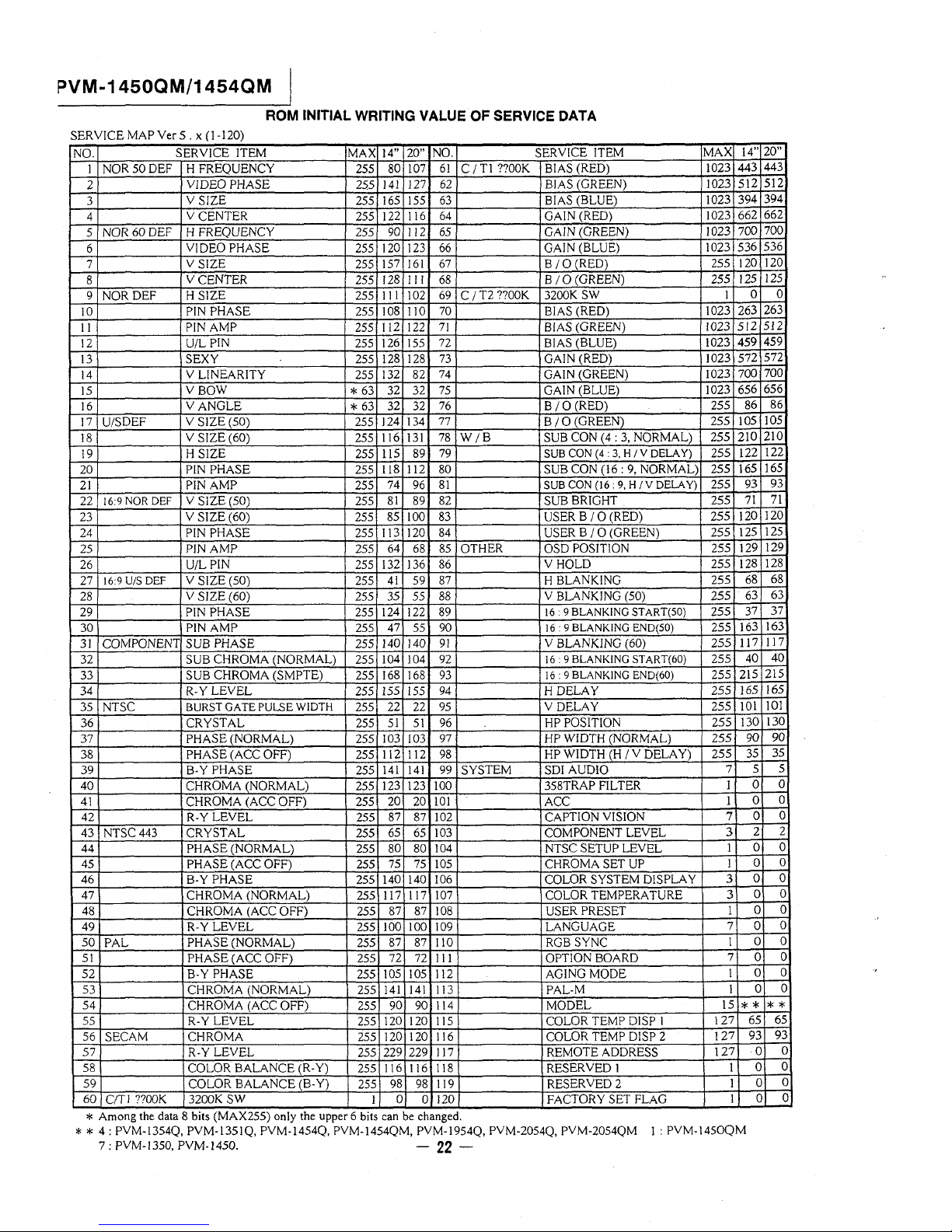
ROM INITIAL WRITING VALUE OF SERVICE DAT A
SERVICE MAP Ver 5. x (J-120)
NO.
SERVICE ITEM
MAX
14" 20" NO. SERVICE ITEM
I
NOR 50DEF H FREQUENCY
255
80
107 61 C /Tl ??OOK BIAS (RED)
2
VIDEO PHASE
255
141 127 62
BIAS (GREEN)
3
V SIZE
255
165 155 63
BIAS (BLUE)
4
VCENTER
255
I22
116 64 GAIN (RED)
5
NOR 60 DEF
H FREQUENCY
255
90 112 65 GAIN (GREEN)
6
VIDEO PHASE
255
120 123 66
GAIN (BLUE)
7
VSJZE
255
157 161
67
B / 0 (RED)
8
VCENTER
255
128
11 l
68
B /O(GREEN)
9
NOR DEF
HSIZE
255
111
102
69 C !T2 ??OOK 3200K SW
10 PIN PHASE 255
108 l 10
70
BIAS (RED)
11
PIN AMP
255
I 12 122
71 BIAS (GREEN)
12 U/L PIN 255
126 155 72
BIAS (BLUE)
13 SEXY 255
128 128
73
GAIN (RED)
14
V LINEARITY
255
132
82
74
GAIN (GREEN)
15
VBOW
* 63
32
32
75 GAIN (BLUE)
16 V ANGLE
* 63
32
32
76
8 /0 (RED)
17
U/SDEF
V SIZE (50)
255
124 134
77
8 /0 (GREEN)
18
V SIZE (60)
255
I 16 131
78
W /8
SUB CON (4: 3, NORMAL)
19 H SIZE 255
115 89
79
SUB CON (4: 3. H /V DELAY)
20 PIN PHASE 255
118 112 80
SUB CON (16: 9, NORMAL)
21
PIN AMP
255
74
96
81
SUB CON (16: 9, H / V DELAY)
22
16:9 NOR DEF V SIZE (50)
255
81
89 82 SUB BRIGHT
23
V SIZE (60)
255
85 100 83 USER B / 0 (RED)
24 PIN PHASE 255
113
120
84 USER B / 0 (GREEN)
25 PIN AMP 255
64
68 85 OTHER OSD POSlTION
26 U/L PIN 255
132 136 86
VHOLD
27 16:9 U/S DEF V SIZE (50)
255
41 59
87
H BLANKING
28
V SIZE (60)
255
35
55
88 V BLANKING (50)
29 PlN PHASE 255
124
122 89
16 · 9 BLANKING START(S0)
30 PIN AMP 255
47 55 90
16 · 9 BLANKING END(S0)
31 COMPONENT SUB PHASE
255
140 140 91 V BLANKJNG (60)
32
SUB CHROMA (NORMAL)
255
104
]04
92
16: 9 BLANKING START(60)
33
SUB CHROMA (SMPTE)
255
168 168 93
16: 9 BLANKING END(60)
34 R-Y LEVEL
255
155
155
94 H DELAY
35 NTSC
BURST GATE PULSE WIDTH
255
22
22
95 V DELAY
36 CRYSTAL
255
51 51 96
HP POSITION
37 PHASE (NORMAL)
255
103 l03
97
HP WIDTH (NORMAL)
38 PHASE (ACC OFF)
255
I 12 112 98
HP WIDTH (H / V DELAY)
39 B-Y PHASE
255
141
141 99 SYSTEM SDI AUDIO
40 CHROMA (NORMAL)
255
123
123 100
358TRAP FILTER
41 CHROMA (ACC OFF)
255 20
20 IOI
ACC
42 R-Y LEVEL
255
87 87
102
CAPTION VISION
43 NTSC 443 CRYSTAL
255
65
65 103 COMPONENT LEVEL
44
PHASE (NORMAL)
255
80
80
104 NTSC SETUP LEVEL
45 PHASE (ACC OFF)
255
75 75
105 CHROMA SET UP
46 B-Y PHASE
255
140 140 106 COLOR SYSTEM D!SPLA Y
47
CHROMA (NORMAL) 255
117 117 107 COLOR TEMPERATURE
48 CHROMA (ACC OFF) 255
87 87
108 USER PRESET
49
R-Y LEVEL
255
JOO 100 109 LANGUAGE
50
PAL
PHASE (NORMAL)
255
87 87
110 RGB SYNC
51
PHASE (ACC OFF) 255
72
72 III
OPTION BOARD
52 B-Y PHASE
255
105 105 112 AGING MODE
53
CHROMA (NORMAL) 255
141 141 I 13 PAL-M
54
CHROMA (ACC OFF)
255
90 90
I 14
MODEL
55 R-Y LEVEL
255
120
120 I 15 COLOR TEMP DISP I
56
SECAM CHROMA 255
120 120 116 COLOR TEMP DISP 2
57
R-Y LEVEL
255
229 229 117 REMOTE ADDRESS
58 COLOR BALANCE (R-Y)
255
I 16
I 16 I 18
RESERVED I
59 COLOR BALANCE (B-Y)
255
98
98
I 19 RESERVED2
60
C/Tl ??OOK 3200K SW
1
0 0 120 FACTORY SET FLAG
* Among the data 8 bits (MAX255) only the upper 6 bits can be changed.
MAX
14"
1023
443
1023 512
1023
394
1023
662
1023
700
1023 536
255 120
255
125
l
0
1023 263
1023 512
1023
459
1023 572
1023 700
1023 656
255
86
255 105
255 210
255 122
255 165
255
93
255
71
255 120
255
125
255
129
255 128
255
68
255
63
255
37
255
163
255 117
255
40
255 215
255
165
255
IOI
255
130
255 90
255
35
7 5
I
0
I
0
7
0
3
2
1
0
I
0
3
0
3
0
1
0
7 0
I
0
7
0
I
0
I
0
15
**
127
65
127
93
127
0
I
0
1
0
I
0
* * 4: PVM-l354Q, PYM-1351Q, PVM-1454Q, PVM-1454QM, PVM-1954Q, PVM-2054Q, PVM-2054QM I: PVM-1450QM
7: PVM-1350, PVM-1450. - 22 -
20"
443
512
394
662
700
536
120
125
0
263
512
459
572
700
656
86
105
210
122
165
93
71
120
125
129
128
68
63
37
163
l l 7
40
215
165
101
130
90
35
5
0
0
0
2
0
0
0
0
0
0
0
0
0
0
**
65
93
0
0
0
0
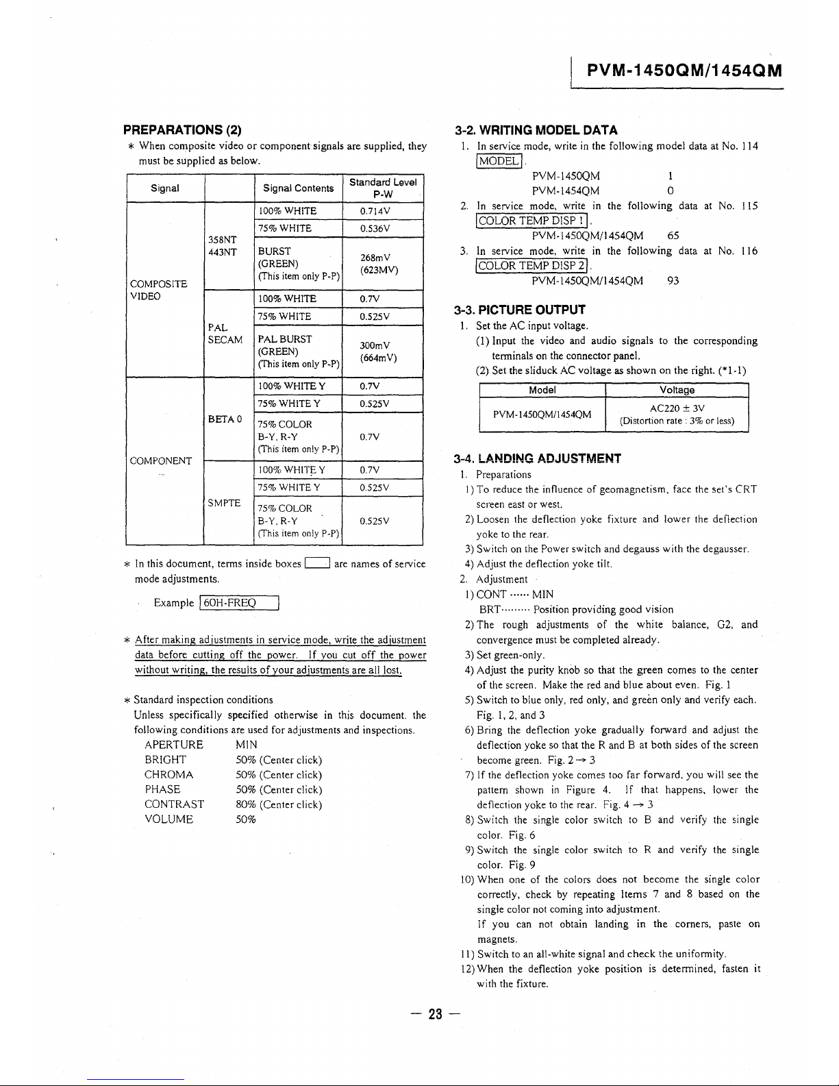
PREPARATIONS (2)
* When composite video or component signals are supplied, they
must be supplied as below.
Signal Signal Contents
Standard Level
P-W
100%WHITE 0.714V
75%WHITE
0.536V
358NT
443NT
BURST
268mV
(GREEN)
(623MV)
COMPOSITE
(This item only P-P)
VIDEO
100%WHITE
0.7V
75%WHITE
0.525V
PAL
SECAM
PAL BURST
300mV
(GREEN)
(664mV)
(This item only P-P)
100%WHITEY 0.7V
75%WHITEY
0.525V
BETAO
75%COLOR
B-Y. R-Y 0.7V
(This item only P-P)
COMPONENT
JOO% WHIT!: Y 0.7V
75% WHITEY
0.525V
SMPTE
75%COLOR
B-Y.R-Y 0.525V
(This item only P-P)
* In this document, terms inside boxes c:=J are names of service
mode adjustments.
Example I 60H-FREQ
* After making adjustments in service mode, write the adjustment
data before cutting off the power. If you cut off the power
without writing, the results of your adjustments are all lost.
* Standard inspection conditions
Unless specifically specified otherwise in this document. the
following conditions are used for adjustments and inspections.
APERTURE MIN
BRIGHT
CHROMA
PHASE
CONTRAST
VOLUME
50% (Center click)
50% (Center click)
50% (Center click)
80% (Center click)
50%
PVM-1450QM/1454QM
3-2. WRITING MODEL DATA
I. In service mode, write in the following model data at No. 114
!MODEL!.
PVM-1450QM
PVM-1454QM
l
0
2. In service mode, write in the following data at No. 115
I COLOR TEMP DISP I , .
PVM-1450QM/1454QM 65
3. In service mode, write in the following data at No. 116
!COLOR TEMP DISP 21.
PVM-1450QM/1454QM 93
3-3. PICTURE OUTPUT
l. Set the AC input voltage.
(l) Input the video and audio signals to the corresponding
terminals on the connector panel.
(2) Set the sliduck AC voltage as shown on the right. (*l-1)
Model
PVM-!450QM/1454QM
Voltage
AC220 ± 3V
(Distortion rate: 3% or less)
3-4. LANDING ADJUSTMENT
I. Preparations
I) To reduce the influence of geomagnetism, face the set's CRT
screen east or west.
2) Loosen the deflection yoke fixture and lower the deflection
yoke to the rear.
3) Switch on the Power switch and degauss with the degausser.
4) Adjust the deflection yoke tilt.
2. Adjustment
I) CONT······ MIN
BRT ......... Position providing good vision
2) The rough adjustments of the white balance, G2, and
convergence must be completed already.
3) Set green-only.
4) Adjust the purity knob so that the green comes to the center
of the screen. Make the red and blue about even. Fig. I
5) Switch to blue only, red only, and green only and verify each.
Fig. !, 2, and 3
6) Bring the deflection yoke gradually forward and adjust the
deflection yoke so that the R and B at both sides of the screen
become green. Fig. 2-" 3
7) If the deflection yoke comes too far forward, you will see the
pattern shown in Figure 4. If that happens, lower the
deflection yoke to the rear. Fig. 4 --;. 3
8) Switch the single color switch to B and verify the single
color. Fig. 6
9) Switch the single color switch to R and verify the single
color. Fig. 9
10) When one of the colors does not become the single color
correctly, check by repeating Items 7 and 8 based on the
single color not coming into adjustment.
If you can not obtain landing in the corners, paste on
magnets.
11) Switch to an all-white signal and check the uniformity.
12) When the deflection yoke position is determined, fasten it
with the fixture.
- 23 -

PVM-1450QM/1454QM
purity control
\https://manualmachine.com/
purity
deflection yoke
R G B
A'=A
A
A'
Fig. 1
Fig. 2
Fig. 3
Fig. 4
Fig. 5
Fig. 6
Fig. 7
GHJ-D-~
Fig. 8 Fig. 9 Fig. 10
3-5. CONVERGENCE ADJUSTMENT
I. Input a dot pattern signal.
CONT ..... · Position providing good vision
BRT .... , .... MJN
2. Align the horizontal R, G, and B dots at the center of the
screen with the H-STAT VR. (*I)
*I: If the H-CENTER adjustment was after the H-STAT
adjustment, re-adjust the H-ST AT.
(The H-CENT VR changes the H-STAT too.)
3. Align the R, G, and B at the center of the screen with the
V-STAT magnets. (*2)
*2 : After the V -ST AT adjustment, paint on the knobs to
lock them.
y
Good example
V-ST AT magnet knobs
While keeping the angles for A
and B equal (!=I'), align the
vertical convergence.
y
Bad example
If the A and B knobs are not
symmetrical (I ,;cc]'), this has
bad effects. The focus may
deteriorate and beam striking
may occur.
4. For HMC, use the 6-pole magnet to adjust the R and B dots to
be symmetrical left and right about the G dot. (*I)
*I :
6-pofe magnet
The HMC adjustment
changes the opening of the
6-pole magnet.
- 24 -
R
G
B
Adjust the 6-pole magnet so
that A=A'. You must maintain
the relationship I* [' while
moving the magnet.
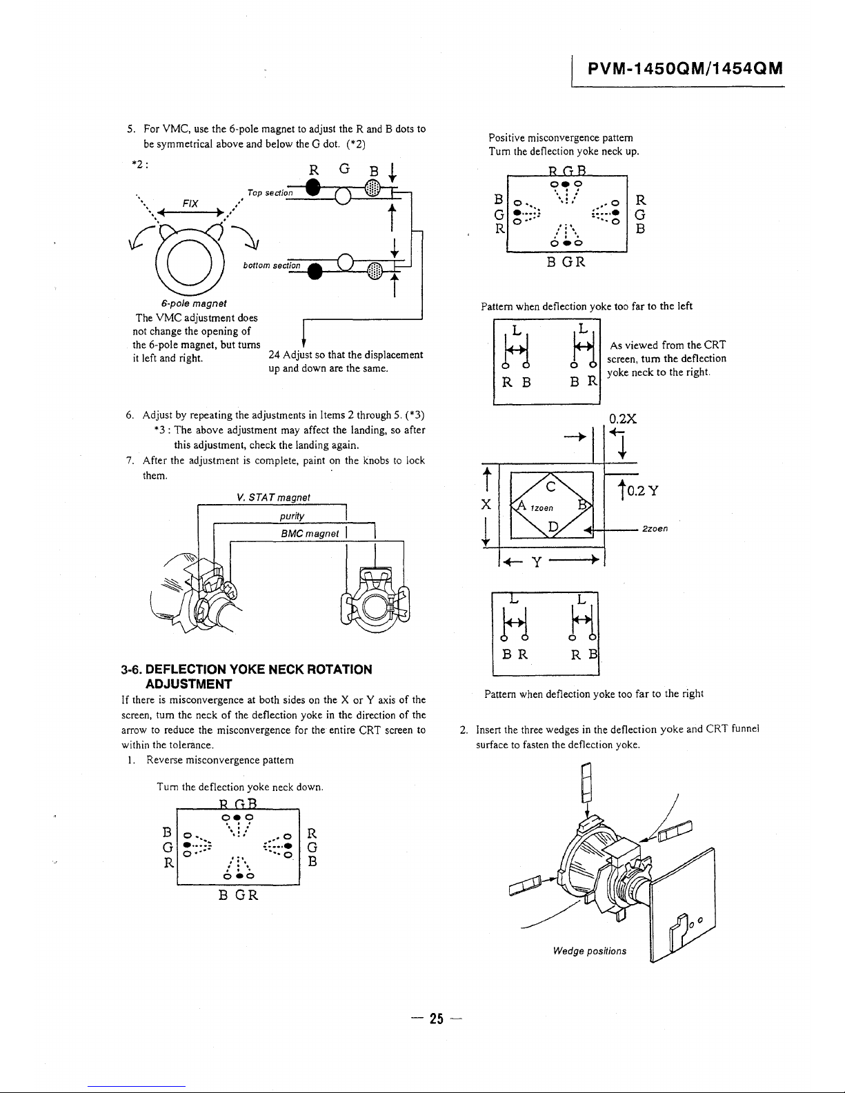
5. For VMC, use the 6-pole magnet to adjust the Rand B dots to
be symmetrical above and below the G dot. (*2)
*2:
R
G
B
Top section
•••• FIX ,• -----1.
;tos··~,m ,oci-ion --,
6-pole magnet
The VMC adjustment does
not change the opening of
the 6-pole magnet, but turns
it left and right.
24 Adjust so that the displacement
up and down are the same.
6. Adjust by repeating the adjustments in Items 2 through 5. (*3)
*3: The above adjustment may affect the landing, so after
this adjustment, check the landing again.
7. After the adjustment is complete, paint on the knobs to lock
them.
V. STAT magnet
purity
BMC magnet
3-6. DEFLECTION YOKE NECK ROTATION
ADJUSTMENT
If there is misconvergence at both sides on the X or Y axis of the
screen, tum the neck of the deflection yoke in the direction of the
arrow to reduce the misconvergence for the entire CRT screen to
within the tolerance.
I. Reverse misconvergence pattern
Turn the deflection yoke neck down.
B o ..
G
•... :::.
o ····
R
'?~9
...
...
...
...
...
. . .
o•o
B GR
R
G
B
PVM-1450QM/1454QM
Positive misconvergence pattern
Turn the defiection yoke neck up.
B o ..
G ~·:;::
R
oeo
...
...
...
...
...
. . .
. . .
. . .
oeo
B GR
R
G
B
Pattern when deflection yoke too far to the left
R
H
As viewed from the CRT
screen, tum the defiection
R B
BR
yoke neck to the right.
t
X
L
2zoen
..,_y
~
L
L
H
H
BR RB
Pattern when defiection yoke too far to the right
2. Insert the three wedges in the deflection yoke and CRT funnel
surface to fasten the deflection yoke.
Wedge positions
- 25 -
PVM-1450QM/1454QM
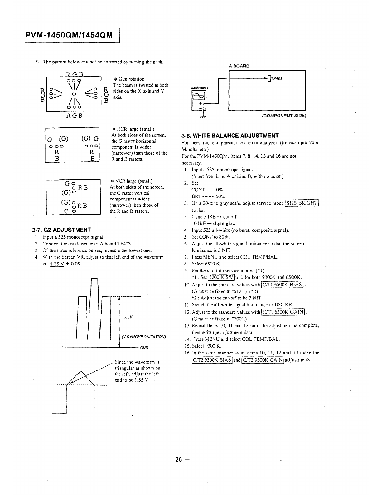
3. The pattern below can not be corrected by turning the neck.
~
000
\II
o........._
/0
g..-
0
-0
/I\
....._o
coo
RGB
G (G)
(G) G
000
000
R
B
og RB
(G)o
(G)gRB
Go
R
B
3-7. G2 ADJUSTMENT
R
G
B
1. Input a 525 monoscope signal.
* Gun rotation
The beam is twisted at both
sides on the X axis and Y
axis.
* HCR large (small)
At both sides of the screen,
the G raster horizontal
component is wider
(narrower) than those of the
R and B rasters.
* VCR large (small)
At both sides of the screen,
the G raster vertical
component is wider
( narrower) than those of
the R and B rasters.
2. Connect the oscilloscope to A board TP403.
3. Of the three reference pulses, measure the lowest one.
4. With the Screen VR, adjust so that left end of the waveform
is : 1.35 Y ± 0.05
1.35V
(V SYNCHRONIZA T/ON)
----------'----GND
Since the wavefom1 is
triangular as shown on
the left, adjust the left
end to be 1.35 Y.
ABOARD
TP403
(COMPONENT SIDE)
3-8. WHITE BALANCE ADJUSTMENT
For measuring equipment, use a color analyzer. (for example from
Minolta, etc.)
For the PVM-1450QM, !terns 7, 8, 14, 15 and 16 are not
necessary.
l. Input a 525 monoscope signal.
(Input from Line A or Line B, with no burst.)
2. Set:
CONT .. ···· 0%
BRT ......... 50%
3. On a 20-tone gray scale, adjust service modelSUB BRIGHT/
so that
0 and 5 IRE___,. cut off
10 IRE__,. slight glow
4. Input 525 all-wh.ite (no burst, composite signal).
5. Set CONT to 80%.
6. Adjust the all-white signal luminance so that the screen
luminance is 3 NIT.
7. Press MENU and select COL TEMP/BAL.
8. Select 6500 K.
9. Put the unit into service mode. (*I)
* l : Set j 3200 K SW I to 0 for both 9300K and 6500K.
IO. Adjust to the standard values with \CIT! 6500K BIAS\.
(G must be fixed at "512".) ( *2)
*2 : Adjust the cut-off to be 3 NIT.
11. Switch the all-white signal luminance to I 00 I RE.
12. Adjust to the standard values with \CIT! 6500K GAIN\.
(G must be fixed at "700" .)
13. Repeat Items 10, 11 and 12 until the adjustment is complete,
then write t]:le adjustment data.
14. Press MENU and select COL TEMP/BAL.
15. Select 9300 K.
16. In the same manner as in Items 10, 11, 12 and 13 make the
/C!T2 9300K BIAS /and /C!T2 9300K GAIN /adjustments.
- 26 -
3-9. BLUE-ONLY WHITE-BALANCE ADJUSTMENT
For the PVM-l 450QM, Items 3, 4, 5, 6, 7 and 8 are not necessary.
I. Switch the user control SW Blue Only On (to set blue-only
mode).
2. Input an all-white signal (no burst composite signal). (*!)
The luminance of the all-white signal must be 100 IRE.
CONT ...... 80%
BRT··· ...... 50%
3. Select COL TEMP/BAL.
4. Select 6500 K.
5. Adjust to the standard values with jcrn 6500K B/O (RED)j
and IC/Tl 6500K 8/0 (GREEN) J.
6. Select COL TEMP/BAL.
7. Select 9300 K.
8. Adjust to the standard values with IC/TI 9300K 8/0 (RED) J
andjC!Tl 9300K B/O (GREEN)j.
9. Check that the white balance is obtained when the all-white
signal luminance is adjusted and the screen luminance is 8
NIT.
~10SUBBRTADJUSTMENT
I. Input a 525 monoscope signal.
2. CONT ...... MIN
Bfn ......... CENTER (SO%)
3. Put the unit into service mode and select I SUB BRIGHT I.
4. AdjustjSUt3 BRIGHT/so that 10 IRE gives a slight glow and
IO I RE gives cut off.
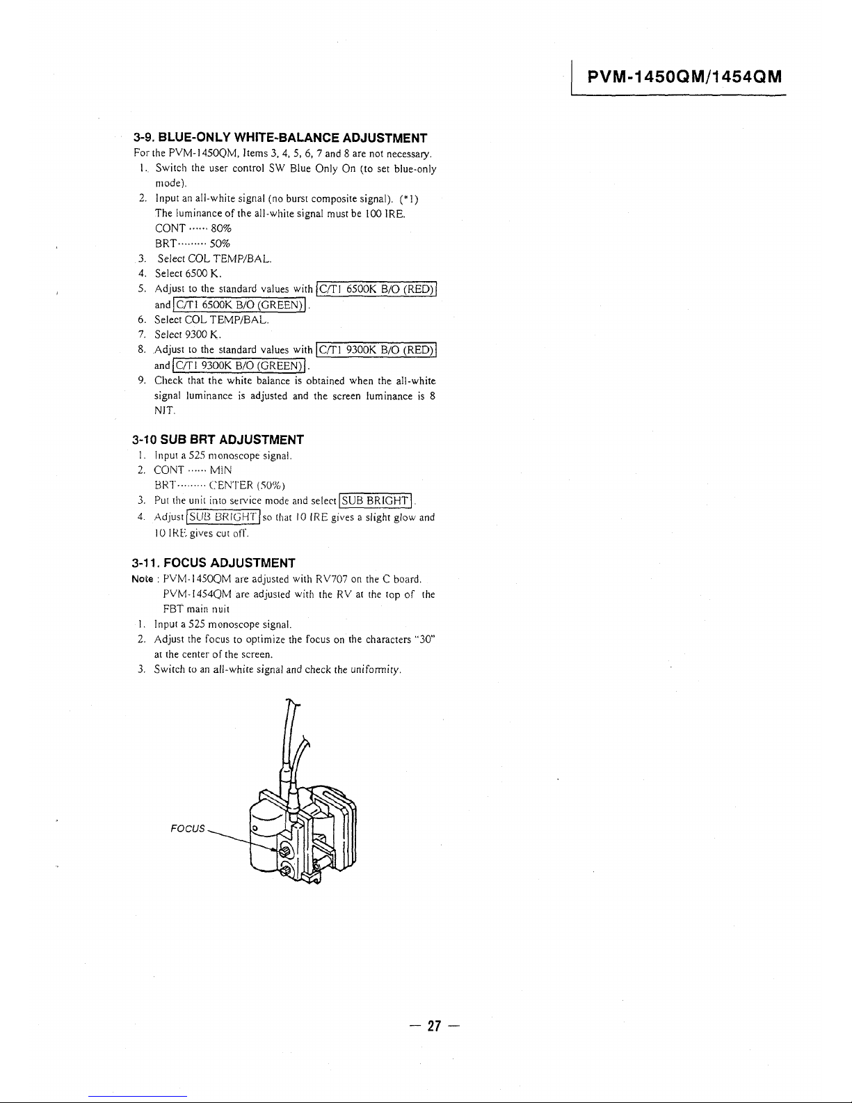
3-11. FOCUS ADJUSTMENT
Note: PVM-14SOQM are adjusted with RV707 on the C board.
PVM- I 454QM are adjusted with the RV at the top of the
FBT main nuit
I. Input a 525 monoscope signal.
2. Adjust the focus to optimize the focus on the characters "30"
at the center of the screen.
3. Switch to an all-white signal and check the uniformity.
FOCUS
- 27 -
PVM-1450QM/1454QM
=>VM-1450QM/1454QM
MEMO
- 28-

PVM-1450QM/1454QM
SECTION 4
SAFETY RELATED ADJUSTMENT
The following adjustments should always be performed when
replacing the following components (marked with B, [;ii on the
schematic diagram).
+B detection ........................... B R1535
Tertiary coil detection ............... B Rl536
Part replosed( [;ii)
Hold Down Circuit.. ....... [;ii A board ICSOO, D533, R1537, C592,
Rl536, C523, Rl560, R551,
C549, R518, C506, C512,
D501, R506, R519, TSO!,
IC507
Beam Current Protector
Circuit ........................ [;ii A board R508, R515, R516, RS! 7,
C513, QSOO, QSll
B+ Regulator Circuit...... [;ii A board Rl535
[;ii G board C603,IC602
I B+ MAX VOLTAGE CONFIRMATION (RV601) I
Standard: 115.0-117.0 VDC
Check Condition: Input voltage: 130-132 VAC
Note : Use NF Power Supply or make sure that
distortion factor is 3% or less.
Input signal : ALL White
Controls : BRT & CONT ~ Minimum
I HOLD-DOWN CIRCUIT VOLTAGE CONFIRMATION I
Check Condition : Input voltage : 130-132 V AC
Input signal : monoscope signal
Controls : BRT & PIC ~ initial reset
B+ voltage : Less than 117.0 V
R690
(1) Hold down circuit (+B Actuation)
a) When IABL = 600 ± 50 µ A, raster goes out at less
than 130.5 V of +B voltage (TP502) by adjusting
1::-, R690 and RV601.
Input signal : ALL white
1::-, R690 : 470-5.6k 1/4 W RN
b) When IABL = 120 ± 20 µ A, raster goes out at less than
134Vof +B voltage(TP502)by adjusting 1::-, R690 and RV601.
Input signal : Dot
(2) Hold down circuit (Tertiary coil detectiol\ voltage)
Confirmatory item : 110.0 V voltage should be applied to
the (11) pin of ICS00.
a) When IABL = 600 ± 50 µ A, raster goes out when
applying less than DC 146.7 V voltage to the (11)
pin (TP503) of ICSOO from outside.
Input signal : ALL white
b) When IABL = 40 ± 20 µ A, raster goes out when
applying less than DC 147.0 V voltage to the (11)
pin (TP503) of ICS00 from outside.
Input signal : Dot
..d!lll!ll!ll! ....
(CONDUCTOR SIDE)
- 29-
PVM-1450QM/1454QM
(COMPONENT SIDE)
'
ABOARD
~03
digital multimeter
'------'-EJ
i
I
(COND~CTOR SIDE)
I
~
30-
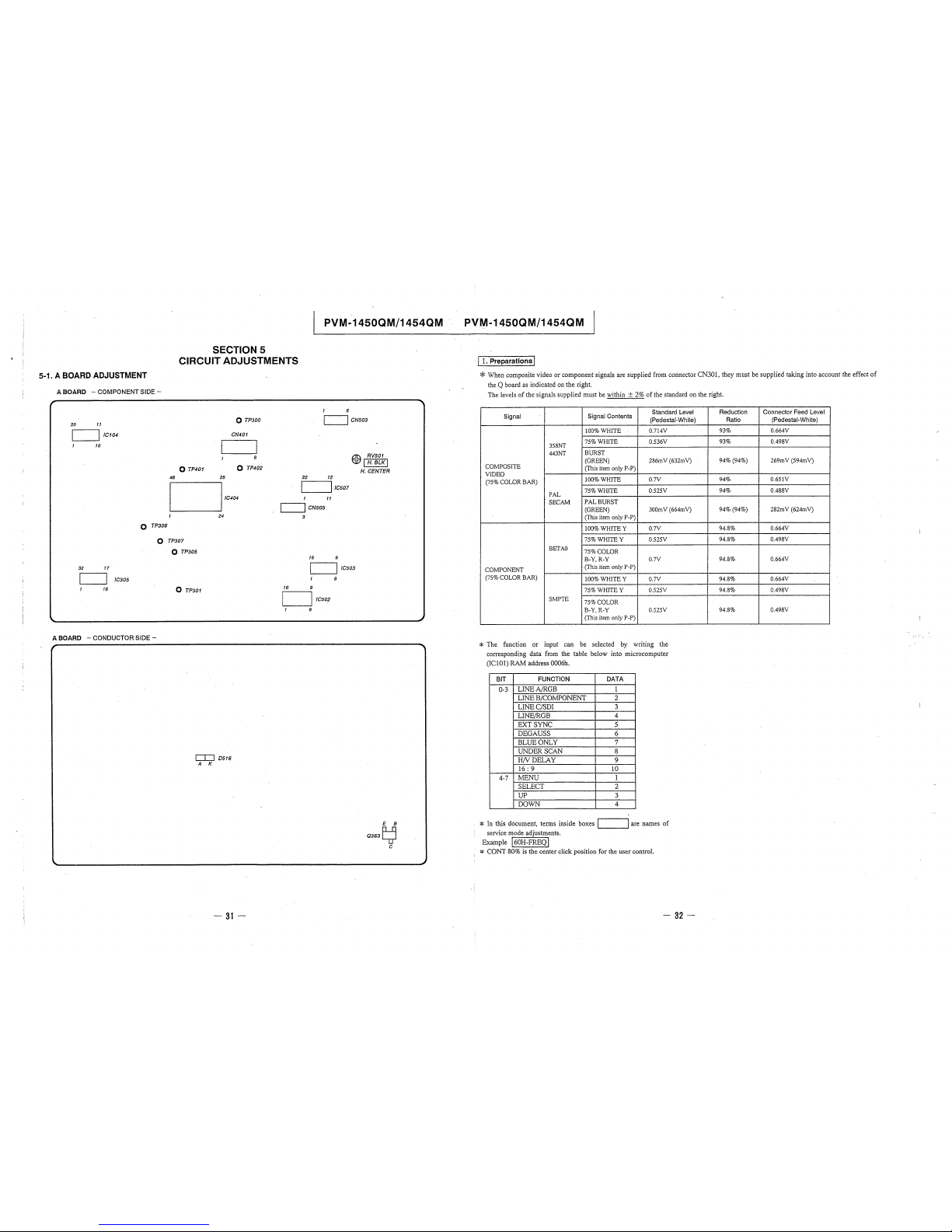
5-1. A BOARD ADJUSTMENT
A BOARD - COMPONENT SIDE -
20 11
.__ _ __.I /Cl 04
10
0 TP306
48
SECTION 5
CIRCUIT ADJUSTMENTS
0 TP401
25
0 TP300
CN401
8
0 TP402
PVM-1450QM/1454QM
1 6
C:=JcN503
22 12
'-----'' /C507
11
~
RV501
'1l7 I H. BLK I
H. CENTER
24
'----'' CN505
3
0 TP307
32 17
/C305
16
A BOARD - CONDUCTOR SIDE -
,
0 TP305
0 TP301
C[J D516
A K
-31-
16
16
9
LJ,cso?
1 8
9
I /C503
8
E B
Q363~
C
PVM-1450QM/1454QM
· I I. Preparations I
* When composite video or component signals are supplied from connector CN301, they must be supplied taking into account the effect of
the Q board as indicated on the right.
The levels of the signals supplied must be within + 2% of the standard on the right.
Signal
Signal Contents
Standard Level
(Pedestal-White)
100%WHITE
0.714V
358NT
75%WHITE
0.536V
443NT
BURST
COMPOSITE
(GREEN)
286mV (632mV)
(This item only P-P)
VIDEO
(75% COWR BAR)
!00%WHITE
0.7V
PAL
75%WHITE 0.525V
SECAM
PAL BURST
(GREEN)
300mV (664mV)
(This item only P-P)
100%WHITEY
0.7V
75%WHITEY
0.525V
BETA0
75%COLOR
B-Y,R-Y
0.7V
COMPONENT
(This item only P-P)
(75% COLOR BAR)
100%WHITEY
0.7V
75%WHITEY 0.525V
SMPTE
75%COLOR
B-Y,R-Y
0.525V
(This item only P-P)
* The function or input can be selected by writing the
corresponding data from the table below into microcomputer
(ICl0l) RAM address 0006h.
BIT
FUNCTION DATA
0-3
LINEA/RGB
1
LINE B/COMPONENT 2
LINEC/SDI 3
LINE/RGB 4
EXT SYNC 5
DEGAUSS 6
BLUEONLY
7
UNDER SCAN 8
HNDELAY 9
16: 9 10
4-7
MENU 1
SELECT 2
UP 3
DOWN 4
* In this document, terms inside boxes ._I __ __.I are names of
service mode adjustments.
Example j60H-FREQI
* CONT 80% is the center click position for the user control.
- 32-
Reduction
Ratio
93%
93%
94% (94%)
94%
94%
94% (94%)
94.8%
94.8%
94.8%
94.8%
94.8%
94.8%
Connector Feed Level
(Pedestal-White)
0.664V
0.498V
269mV (594mV)
0.651V
0.488V
282mV (624mV)
0.664V
0.498V
0.664V
0.664V
0.498V
0.498V
 Loading...