

Sony Trinitron PVM-1353, Trinitron PVM-1453MD Service Manual
PVM· 1353MD/1453MD
SERVICE MANUAL
CJ
/
/
__ ,
US Model
Canadian Model
PVM-1353MD
Chassis No. SCC-H31 B-A
AEPModel
PVM-1453MO
Chassis No. SCC-H29C-A
SPECIFICATIONS (PVM-1353MD)
Video signal
Color system
Resolution
Aperture correction
Frequency response
Synchronization
NTSC. PAL
600 TV lines
0 dB-+6.0 dB
LINE 9.0 MHz (-3 dB)
RGB 10.0 MHz (-3 dB)
AFC time constant 1.0 msec.
Picture performance
Overscan
Normal scan
Underscan
Linearity
Convergence
20% overscan of CRT effective
screen area
7% overscan of CRT effective screen
area
5% underscan of CRT effective
screen area
Horizontal: Less than 4% (typical)
Vertical: Less than 4% (typical)
Central area
0.6 mm (typical)
Peripheral area
0.8 mm (typical)
Raster size stability
H 1.0%, V 1.5%
High voltage regulation
CRT
Color temperature
Inputs
Y/CIN
VIDEO IN
3.5'k
SMPTE-C phosphor
6500K/5600K/USER (3200K
-
10000K, factory setting is 6500K)
4-pin mini DIN connector
See the pin assignmem on the
page 2.
BNC connector I Vp-p ±6 dB, sync
negative
AUDIO IN phono jack, -5 dBu, more than 47k
ohms
R/R-Y IN, G/Y IN, B/B-Y IN
R, G, B channels
Sync on green
BNC connector
0.7 Vp-p ±6 dB
1.0 Vp-p Sync negative, 75 ohms
terminated
- Continued on next page:-
TRINITRON® COLOR VIDEO MONITOR
MICROFILM
SONY:
PVM-1353MD/1453MD
R-Y, B-Y channels
Y channel
EXT SYNC IN
Outputs
Y/C OUT
0.7 Vp-p ±6 dB
1.0 Vp-p±6dB
(Standard color bar signal of 75%
chrominance)
BNC connector composite sync
4 Vp-p ±6 dB, negative
4-pin mini DIN connector. 75 ohms
terminated
VIDEO OUT BNC
connector. 75 ohms terminated
AUDIO OUT phono jack
R/R-Y OUT. G/Y OUT.
BIB-Y OUT
EXT SYNC OUT
DC OUT
Speaker output
Remote input
REMOTE
I
RS-232C
General
BNC connector, 75 ohms terminated
BNC connector, 75 ohms terminated
5 V/1 A
Output level 0.8 W
8-pin mini DIN
See
the pin assig11111c111 011 1hc
page 2.
9-pin D-sub
See the pin
assignment 011 the
page 2.
Power requirements 120 V AC. 50/60 Hz
1.3A
Capable of JOO to 240V operation
Operating temperature range
0-35°C
Storage temperature range
-I0-+40°C
Humidity
O - 90%
Dimensions Approx. 346 x 340 x 411.5 mm
(w/h/d)
Mass
(13
5
/8 x 131/2 x 161/4 inches)
not incl. projecting
pans and controls
Approx. 16.7 kg (36 lb 14 oz)
Accessory supplied AC power cord
(I)
0 dBu = 0.775 Vr.111.s.
AC plug holder (I)
Splash proof covers (2)
Control panel cover (I)
Panel hinges (2)
Remote Control Connector
8-pin mini DIN (I)
Operating Instructions ( I)
Interface Manual for Programmers (I)
Quick Reference Card (I)
Double-sided adhesive tapes (4)
Design and specifications are subject to change without
notice.
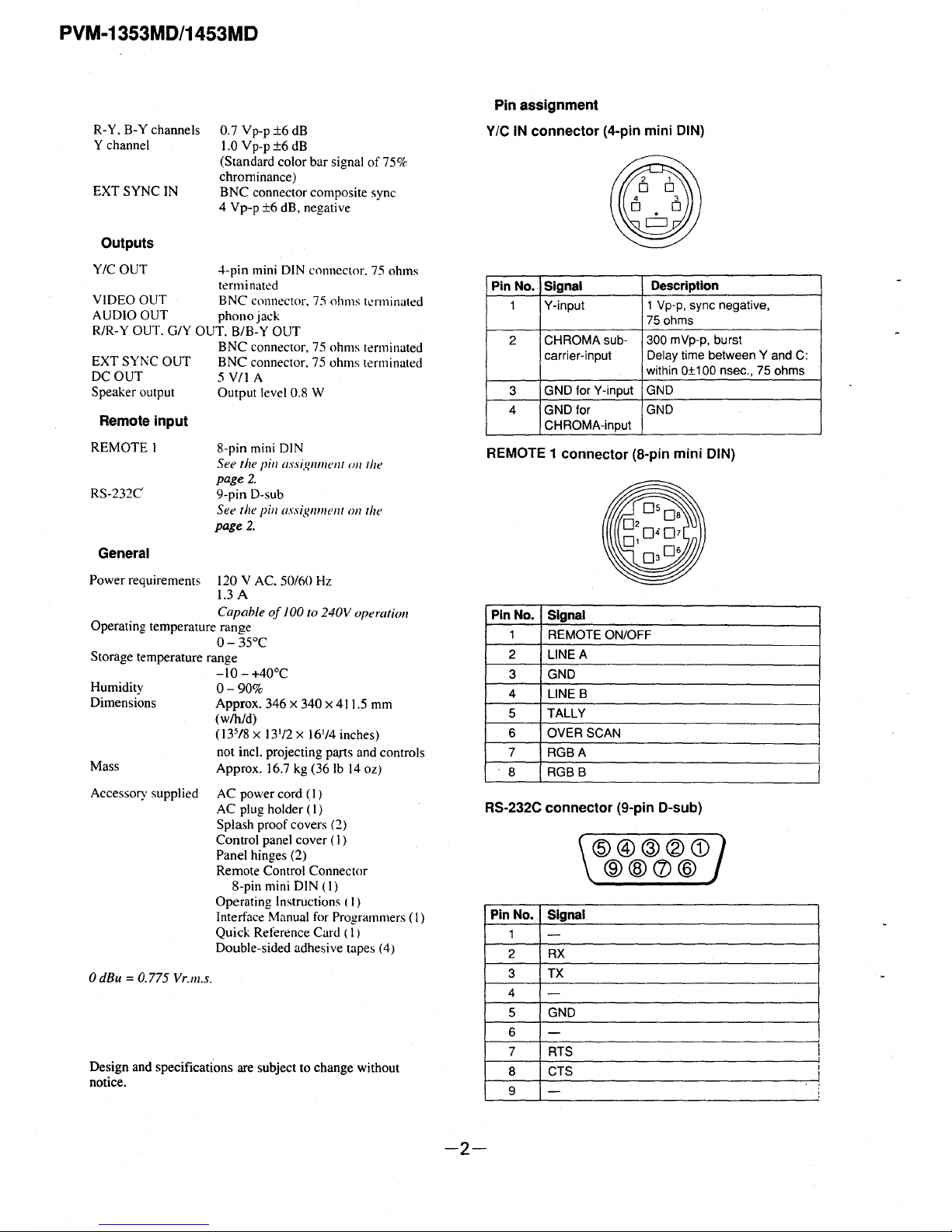
Pin assignment
V/C IN connector (4-pin mini DIN)
Pin No. Signal
Description
1 Y-input
1 Vp-p, sync negative,
75 ohms
2
CHROMA sub-
300 mVp-p, burst
carrier-input
Delay time between Y and C:
within 0±100 nsec., 75 ohms
3
GND for Y-input GND
4 GND for
GND
CHROMA-input
REMOTE 1 connector (8-pin mini DIN)
Pin No. Signal
1 REMOTE ON/OFF
2
LINEA
3 GND
4
LINE B
5 TALLY
6
OVER SCAN
7 RGBA
8 RGBB
RS-232C connector (9-pin D-sub)
Pin No.
1
2
3
4
5
6
7
8
9
-2-
Signal
-
RX
TX
-
GND
-
RTS
CTS
-
@@@®G)
®@CD@
PVM· 1353MD/1453MD
SONY.'.'..
SERVICE MANUAL
CORRECTION· 1
File this correction with the service manual.
• INTRODUCTION
VM '8ts
US Model
Canadian Model
PVM-1353MD
Chassis No. SCC-H31B-A
AEPModel
PVM-1453MD
Chassis No. SCC-H29C-A
DISASSEMBLY and EXPLODED VIEWS have some additions. (PVM-1353MD only)
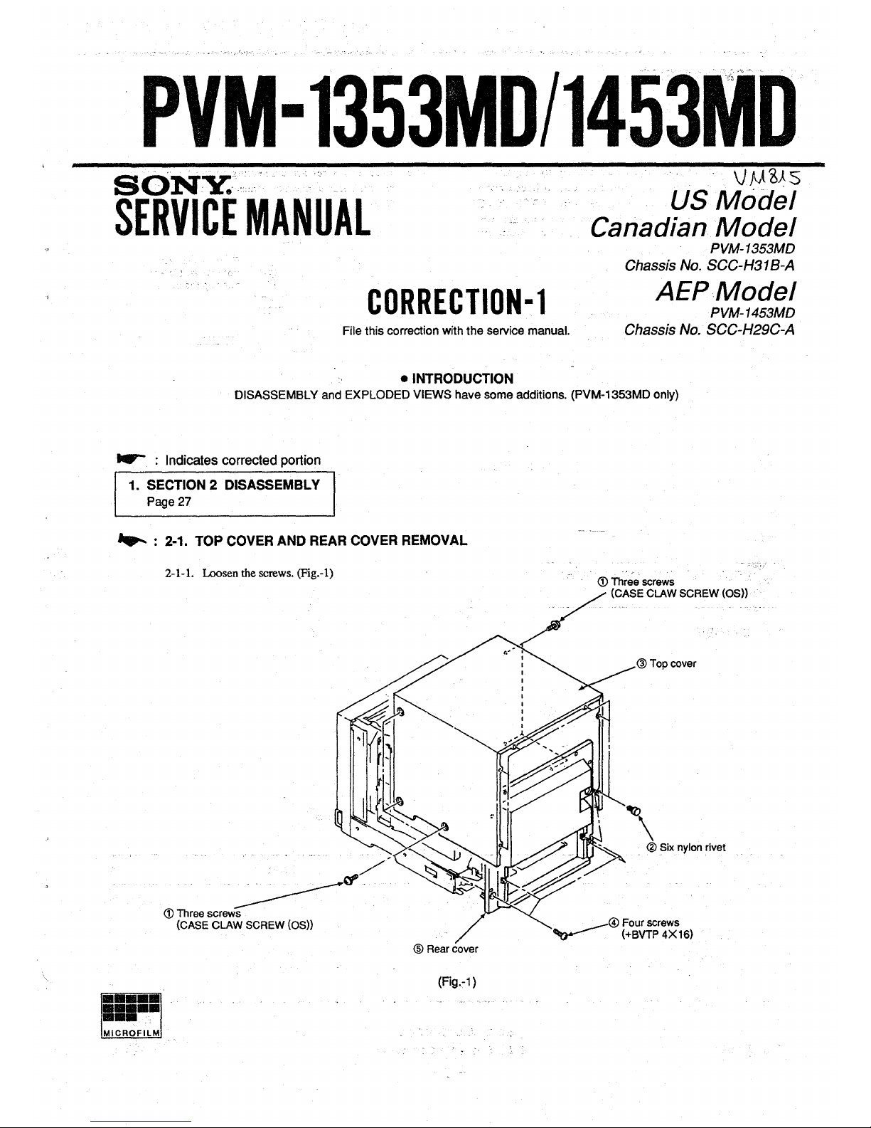
-- : Indicates corrected portion
1. SECTION 2 DISASSEMBLY
Page 27
...... : 2-1. TOP COVER AND REAR COVER REMOVAL
2-1-1. Loosen the screws. (Fig.-1)
® Rear cover
(Fig.~1)
., , ..
<D Three screws
(CASE CLAW SCREW (OS))
@Top cover
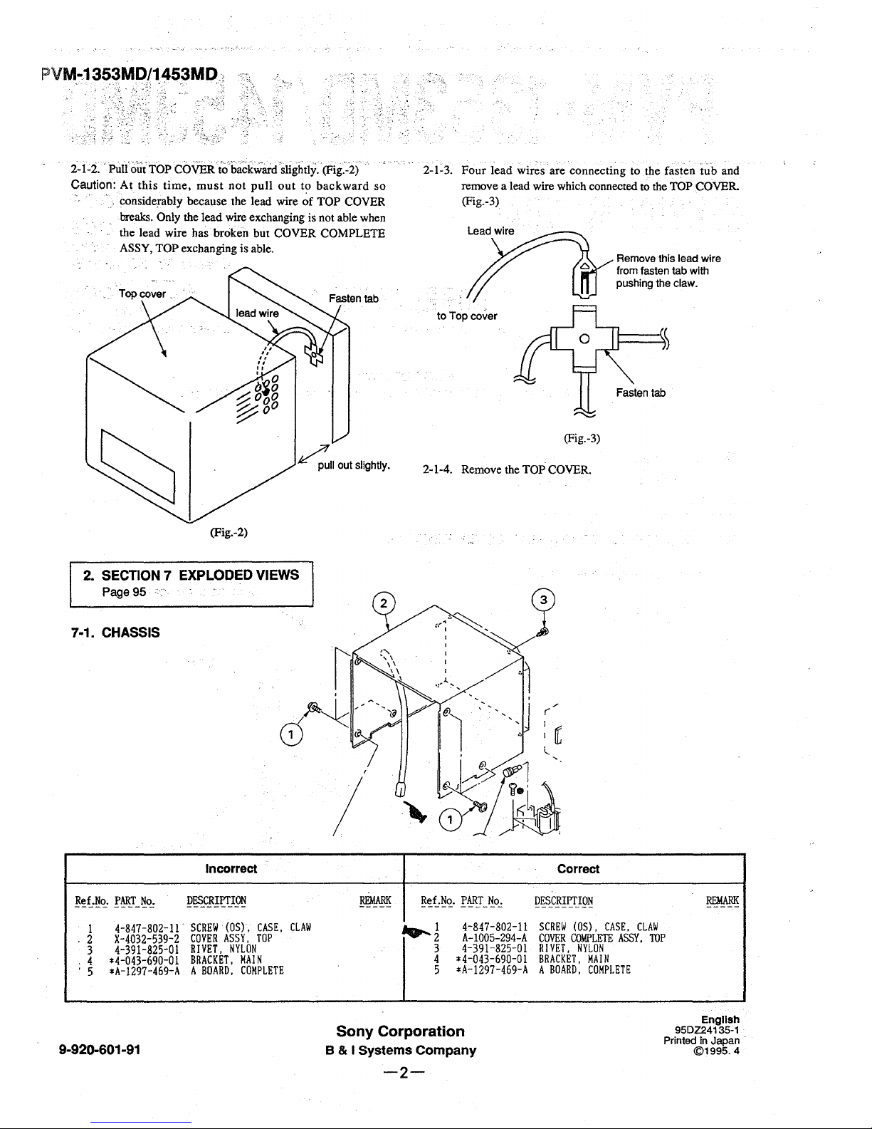
2-1~2 .. Pult'o~1>:rop COVER toba~kward0slightly. (Fig.'~2) .·.
Caution: At this time, must not pull out to backward so
· , considerably because the lead wire of TOP COVER
breaks. Only the lead wire exchanging is not able when
the lead wire has broken but COVER COMPLETE
ASSY, TOP exchanging is able.
~II out slightly.
(Fig.-2)
2. SECTION 7 EXPLODED VIEWS
Page 95
7-1. CHASSIS
I
Incorrect
Ref.No. PART No.
DESCRIPTION
REMARK
1
4-847-802-11. SCREW (OS), CASE.
CLAW
. 2
X-4032-539-2 COVER ASSY, TOP
3
4-391-825-01
RIVET, NYLON
4
*4-043-690-01
BRACKET,
MAIN
' 5
*A-1297-469-A
A BOARD, COMPLETE
2-1~3. Four lead wir~s are connecting to the fasten tub and
remove a lead wire which connected to the TOP COVER.
(Fig.-3)
to Top cover
(Fig.-3)
Remove this lead wire
from fasten tab with
pushing the claw.
Fasten tab
2-1-4. Remove the TOP COVER.
Correct
Ref.No. PART No.
DESCRIPTION
~
~J
4-847-802-11
SCREW (OS), CASE, CLAW
A-1005-294-A COVER COMPLETE ASSY,
TOP
3
4-391-825-01
RIVET, NYLON
4 *4-043-690-01
BRACKET, HAIN
5
*A-1297-469-A
A BOARD, COMPLETE
Sony Corporation
English
95DZ24135-1
Printed in Japan
©1995.4
9-920-601-91
B & I Systems Company
-2-
PVM-1353MD/1453MC
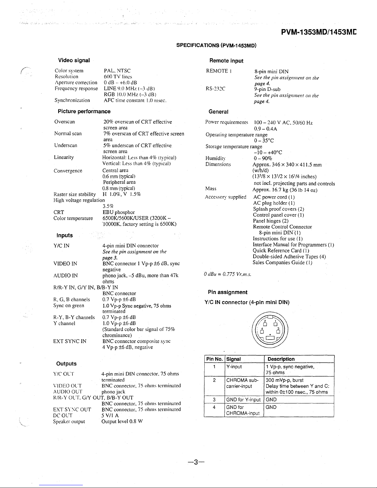
SPECIFICATIONS (PVM-1453MD)
Video signal
Color system
Resolution
Aperture correction
Frequency response
Synchronization
PAL. NTSC
600 TV lines
0 dB
- +6.0 dB
LINE
9.0 MHz (-3 dB)
RGB
IO.O MHz (-3 dB)
AFC time constant
1.0 111sec.
Picture performance
Overscan
Normal scan
Underscan
Linearity
20% overscan of CRT effective
screen area
7% overscan of CRT effective screen
area
5% underscan of CRT effective
screen area
Horizontal:
Less than 4% (typical)
Vertical: Less than 4% (typical)
Convergence Central area
0.6
mm (typical)
Peripheral area
0.8 mm (typical)
Raster size stability
H I .O<x, V I .5%
High voltage regulation
3.5%
CRT EBU phosphor
Color temperature 6500K/5600K/USER (3200K
-
·10000K, factory setting is 6500K)
Inputs
Y/CIN
VIDEO IN
AUDIO IN
4-pin mini DIN connector
See the pin assignment on the
page 3.
BNC connector I Vp-p ±6 dB, sync
negative
phono jack, -5 dBu, more than 47k
ohms
R/R-Y IN, G/Y IN, B/B-Y IN
R. G, B channels
Sync on green
BNC connector
0.7 Vp-p ±6 dB
1.0 Yp-p Sync negative, 75 ohms
terminated
R-Y, B-Y channels 0.7 Vp-p ±6 dB
Y channel 1.0 V p-p ±6 dB
EXT SYNC IN
Outputs
Y/C OLT
(Standard color bar signal of 75%
chrominance)
BNC connector composite sync
4 Vp-p ±6 dB, negative
4-pin mini DIN connector. 75 ohms
terminated
VIDEO OL'.T BNC connector, 75 ohms terminated
AUDIO Ol;T phonojack
R/R-Y m·T. G/Y OUT. BIB-Y OUT
EXT
SY:\C OUT
DC OCT
Speaker output
BNC connector. 75 ohms terminated
BNC connector, 75 ohms terminated
5 V/1 A
Output level 0.8 W
Remote input
REMOTE I
RS-232C
General
8-pin mini DIN
See the pin assignment on the
page 4.
9-pin D-sub
See the pin assignment on the
page 4.
Power requirements 100 - 240 V AC. 50/60 Hz
0.9-0.4A
Operating temperature range
0-35°C
Storage temperature range
-I0-+40°C
Humidity
O - 90%
Dimensions Approx. 346 x 340 x 4 I 1.5 mm
(w/h/d)
(13
5
/8 x 131/2 x 161/4 inches)
not incl. projecting parts and controls
Mass Approx. 16.7 kg (36 lb 14 oz)
Accessory supplied AC power cord
(I)
AC plug holder (I)
Splash proof.covers (2)
Control panel cover
(I)
Panel hinges (2)
Remote Control Connector
8-pin mini
DfN(l)
Instructions for use ( 1)
Interface Manual for Programmers (I)
Quick Reference Card (I)
Double-sided Adhesive Tapes (4)
Sales Companies Guide (
1)
0 dB11 = 0. 775 Vr.111.s.
Pin assignment
Y/C IN connector (4-pin mini DIN)
Pin No.
Signal Description
1 Y-input 1 Vp-p, sync negative,
75 ohms
2
CHROMA sub- 300 mVp-p, burst
carrier-input Delay time between Y and C:
within 0±100 nsec., 75 ohms
3 GND for Y-input GND
4 GND for GND
CHROMA-input
-3-
PVM-1353MD/1453MD
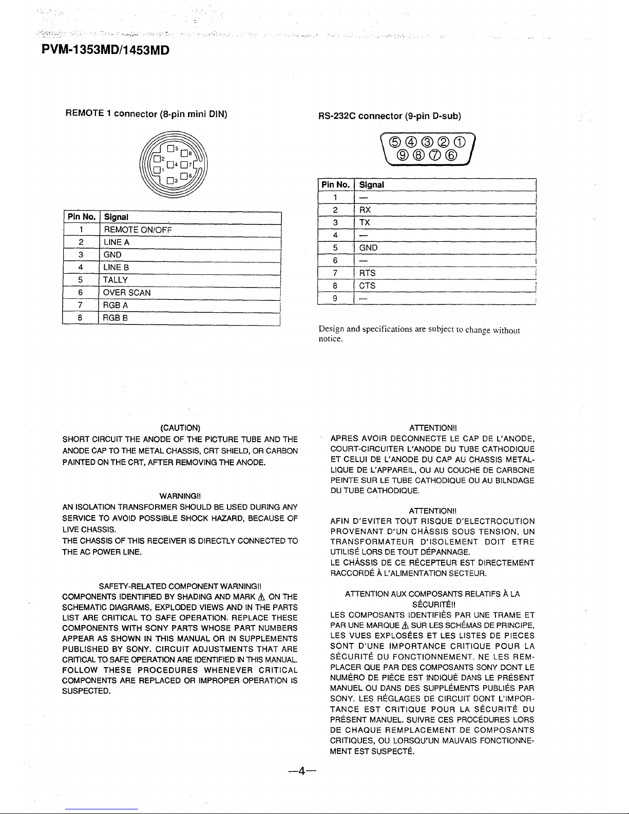
REMOTE 1 connector (8-pin mini DIN)
Pin No.
Signal
1
REMOTE ON/OFF
2
LINE A
3 GND
4
LINE B
5 TALLY
6
OVER SCAN
I
;
7
RGBA
I
8 RGB B
(CAUTION)
SHORT CIRCUIT THE ANODE OF THE PICTURE TUBE AND THE
ANODE CAP TO THE METAL CHASSIS, CRT SHIELD, OR CARBON
PAINTED ON THE CRT, AFTER REMOVING THE ANODE.
WARNINGII
AN ISOLATION TRANSFORMER SHOULD BE USED DURING ANY
SERVICE TO AVOID POSSIBLE SHOCK HAZARD, BECAUSE OF
LIVE CHASSIS.
THE CHASSIS OF THIS RECEIVER IS DIRECTLY CONNECTED TO
THE AC POWER LINE.
SAFETY-RELATED COMPONENT WARNING!!
COMPONENTS .IDENTIFIED BY SHADING AND MARK
& ON THE
SCHEMATIC DIAGRAMS, EXPLODED VIEWS AND IN THE PARTS
LIST ARE CRITICAL TO SAFE OPERATION. REPLACE THESE
COMPONENTS WITH SONY PARTS WHOSE PART NUMBERS
APPEAR AS SHOWN IN THIS MANUAL OR IN SUPPLEMENTS
PUBLISHED BY SONY. CIRCUIT ADJUSTMENTS THAT ARE
CRITICAL TO SAFE OPERATION ARE IDENTIFIED IN THIS MANUAL
FOLLOW THESE PROCEDURES WHENEVER CRITICAL
COMPONENTS ARE REPLACED OR IMPROPER OPERATION IS
SUSPECTED.
-4-
RS-232C connector (9-pin D-sub)
Pin No.
1
2
3
4
5
6
7
8
9
Signal
-
RX
TX
-
GND
-
I ATS
CTS
-
@@@®CD
®@CV@
Design and specifications are subject to chanl!e without
notice.
~
ATTENTION!!
APRES AVOIR DECONNECTE LE CAP DE L'ANODE,
COURT-CIRCUITER L'ANODE DU TUBE CATHODIQUE
ET CELUI DE L'ANODE DU CAP AU CHASSIS METALLIQUE DE L'APPAREIL, OU AU COUCHE DE CARBONE
PEINTE SUR LE TUBE CATHODIQUE OU AU BILNDAGE
DU TUBE CATHODIQUE.
ATTENTION!!
AFIN D'EVITER TOUT RISQUE D'ELECTROCUTION
PROVENANT D'UN CHASSIS SOUS TENSION, UN
TRANSFORMATEUR D'ISOLEMENT DOIT ETRE
UTILISE LORS DE TOUT DEPANNAGE.
LE CHASSIS DE CE RECEPTEUR EST DIRECTEMENT
RACCORDE
A L'ALIMENTATION SECTEUR.
ATTENTION AUX COMPOSANTS RELATIFS
A LA
SECURITE!!
LES COMPOSANTS IDENTIFIES PAR UNE TRAME ET
PAR UNE MARQUE
& SUR LES SCHEMAS DE PRINCIPE,
LES VUES EXPLOSEES ET LES LISTES DE PIECES
SONT D'UNE IMPORTANCE CRITIQUE POUR LA
SECURITE DU FONCTIONNEMENT. NE LES REMPLACER QUE PAR DES COMPOSANTS SONY DONT LE
NUMERO DE
PIECE EST INDIQUE DANS LE PRESENT
MANUEL OU DANS DES SUPPLEMENTS PUBLIES PAR
SONY. LES REGLAGES DE CIRCUIT DONT L'IMPOR-
TANCE EST CRITIQUE POUR LA
SECURITE DU
PRESENT MANUEL. SUIVRE CES PROCEDURES LORS
DE CHAQUE REMPLACEMENT DE COMPOSANTS
CRITIQUES, OU LORSQU'UN MAUVAIS FONCTIONNEMENT EST SUSPECTE.
!
I
I
I
i
I
I
I
i
'
I
!
PVM-1353MD/1453MD
SAFETY CHECK-OUT
(US Model only)
After correcting the original service problem,
perform the following safety checks before releasing
the set to the customer:
1. Check the area of your repair for unsoldered or
poorly-soldered connections. Check the entire
board surface for solder splashes and bridges.
2. Check the interboard wiring to ensure that no
wires are "pinched" or contact high-wattage
resistors.
3, Check that all control knobs, shields, covers,
ground straps, and mounting hardware have
been replaced. Be absolutely certain that you
have replaced all the insulators.
4. Look for unauthorized replacement parts, par-
ticularly transistors, that were installed during
a previous repair. Point them out to the cus-
tomer and recommend their replacement.
5. Look for parts which, though functioning, show
obvious signs of deterioration. Point them out
to the customer and recommend their replace-
ment.
6. Check the line cords for cracks and abrasion.
Recommend the replacement of any such line
cord to the customer.
7. Check the B+ and HV to see if they are at the
values specified. Make sure your instruments
are accurate; be suspicious of your HV meter if
sets always have low HY.
8. Check the metal trim, metallized knobs,
screws, and all other exposed metal parts
for AC leakage.
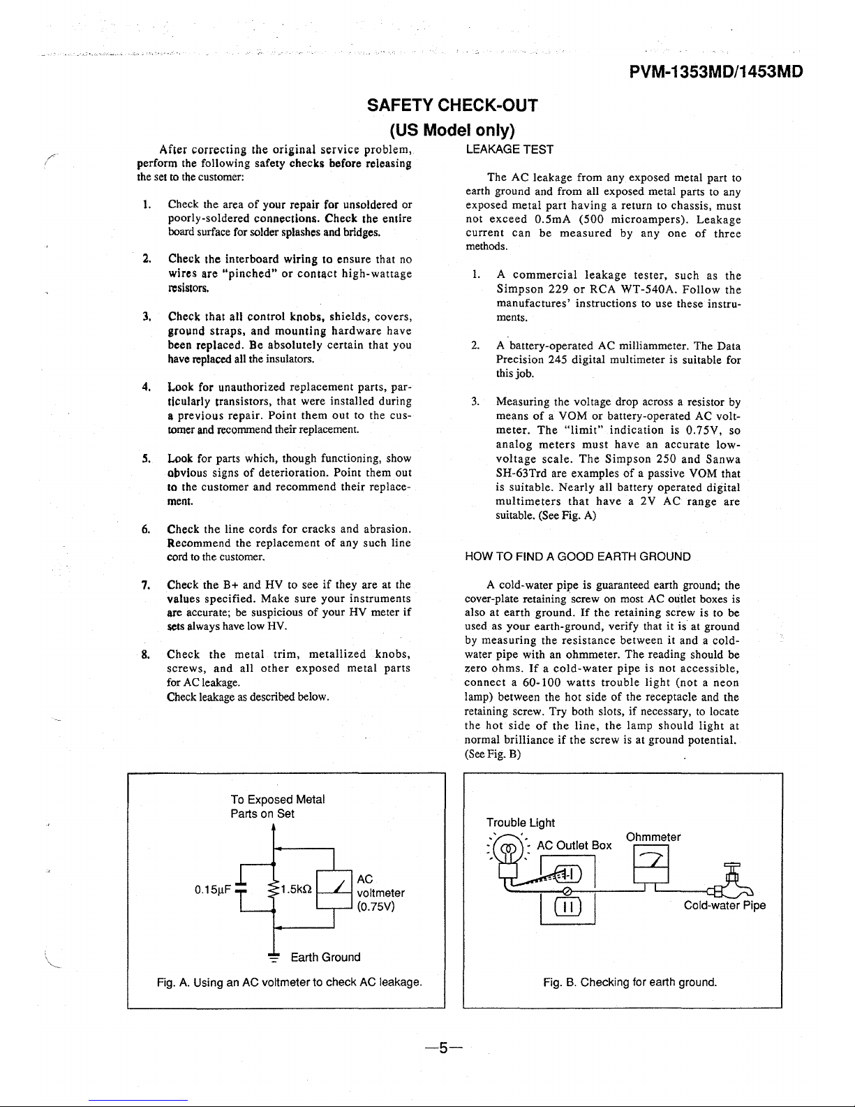
Check leakage as described below.
To Exposed Metal
Parts on Set
0.15µF
1.5kQ
AC
voltmeter
(0.75V)
-= Earth Ground
Fig. A. Using an AC voltmeter to check AC leakage.
-5-
LEAKAGE TEST
The AC leakage from any exposed metal part to
earth ground and from all exposed metal parts to any
exposed metal part having a return to chassis, must
not exceed 0.5mA (500 microampers). Leakage
current can be measured by any one of three
methods.
I. A commercial leakage tester, such as the
Simpson 229 or RCA WT-540A. Follow the
manufactures' instructions to use these instruments.
2. A battery-operated AC milliammeter. The Data
Precision 245 digital multimeter is suitable for
this job.
3. Measuring the voltage drop across a resistor by
means of a VOM or battery-operated AC voltmeter. The "limit" indication is 0.75V, so
analog meters must have an accurate lowvoltage scale. The Simpson 250 and Sanwa
SH-63Trd are examples of a passive VOM that
is suitable. Nearly all battery operated digital
multimeters that have a 2V AC range are
suitable. (See Fig. A)
HOW TO FIND A GOOD EARTH GROUND
A cold-water pipe is guaranteed earth ground; the
cover-plate retaining screw on most AC outlet boxes is
also at earth ground.
If the retaining screw is to be
used as your earth-ground, verify that it is at ground
by measuring the resistance between it and a cold-
water pipe with an ohmmeter. The reading should be
zero ohms.
If a cold-water pipe is not accessible,
connect a 60-100 watts trouble light (not a neon
lamp) between the hot side of the receptacle and the
retaining screw. Try both slots, if necessary, to locate
the hot side of the line, the lamp should light at
normal brilliance if the screw is at ground potential.
(See Fig. B)
Trouble Light
Ohmmeter
Cold-water Pipe
Fig. B. Checking for earth ground.
PVM-1353MD/1453MD
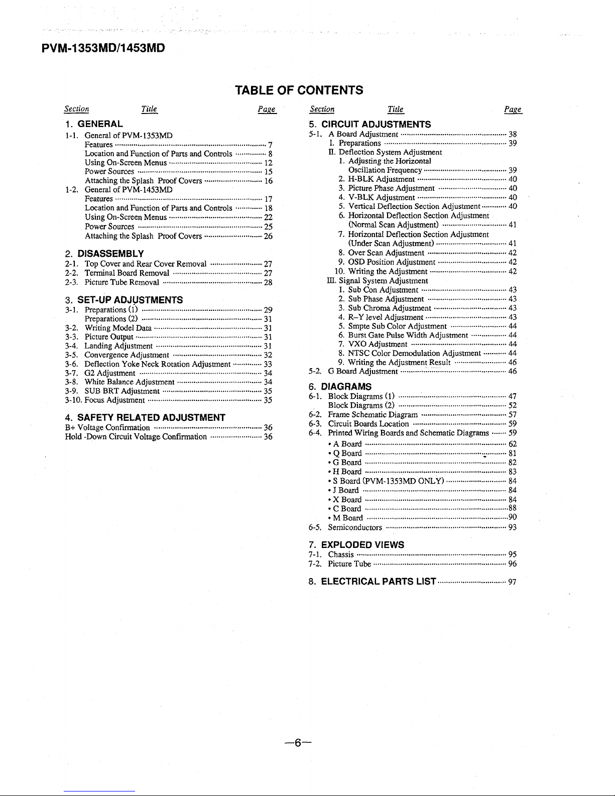
TABLE OF CONTENTS
1. GENERAL
1-1. General of PVM-1353MD
Features········································································· 7
· Location and Function of Parts and Controls ··············· 8
Using On-Screen Menus ............................................. 12
Power Sources ............................................................ 15
Attaching the Splash Proof Covers ............................ 16
1-2. General of PVM-1453MD
Features ......... ············ ········ ·········· ·················· ······ ·· ······ 17
Location and Function of Parts and Controls ............. 18
Using On-Screen Menus············································· 22
Power Sources ············ ······ ······················ .................... 25
Attaching the Splash Proof Covers ···························· 26
2. DISASSEMBLY
2-1. Top Cover and Rear Cover Removal ························· 27
2-2. Terminal Board Removal ··········································· 27
2-3. Picture Tube Removal ················································ 28
3. SET-UP ADJUSTMENTS
3-1. Preparations (1) ·························································· 29
Preparations (2) ...... ···· .................................. ·············· 31
3-2. Writing Model Data ···················································· 31
3-3. Picture Output····························································· 31
3-4. Landing Adjustment ·· ··················· ·· ···· ······ ·············· .... 31
3-5. Convergence Adjustment ........................................... 32
3-6. Deflection Yoke Neck Rotation Adjustment·············· 33
3-7. 02 Adjustment ........................................................... 34
3-8. White Balance Adjustment ········································· 34
3-9. SUB BRT Adjustment ................................................ 35
3-10. Focus Adjustment ··························· .................. ······ .... 35
4. SAFETY RELATED ADJUSTMENT
B+ Voltage Confirmation ················ ···· ···· ............................ 36
Hold -Down Circuit Voltage Confirmation ························· 36
5. CIRCUIT ADJUSTMENTS
5-1. A Board Adjustment ··· ···· .............................. ···· .. ···· ···· 38
I. Preparations · ········ ···· ········ ·· ···· ·················· ·· ............ 39
II. Deflection System Adjustment
1. Adjusting the Horizontal
Oscillation Frequency ········································ 39
2. H-BLK Adjustment ··········································· 40
3. Picture Phase Adjustment ································· 40
4. V-BLK Adjustment ........................................... 40
5. Vertical Deflection Section Adjustment············ 40
6. Horizontal Deflection Section Adjustment
(Normal Scan Adjustment) ............................... 41
7. Horizontal Deflection Section Adjustment
(Under Scan Adjustment)·································· 41
8. Over Scan Adjustment ······································ 42
9. OSD Position Adjustment ................................. 42
10. Writing the Adjustment ..................................... 42
ill. Signal System Adjustment
1. Sub Con Adjustment ......................................... 43
2. Sub Phase Adjustment ······································ 43
3. Sub Chroma Adjustment ................................... 43
4. R-Y level Adjustment ....................................... 43
5. Smpte Sub Color Adjustment ...........................
44
6. Burst Gate Pulse Width Adjustment ................. 44
7. VXO Adjustment .............................................. 44
8. NTSC Color Demodulation Adjustment ........... 44
9. Writing the Adjustment Result ......................... 46
5-2. G Board Adjustment ............ : .. : ................................... 46
6. DIAGRAMS
6-1. Block Diagrams (1) ···················································· 47
Block Diagrams (2) ···················································· 52
6-2. Frame Schematic Diagram ......................................... 57
6-3. Circuit Boards Location ············································· 59
6-4. Printed Wiring Boards and Schematic Diagrams ······· 59
• A Board···································································· 62
:
~
:~:1 :::::::::::::::::::::::::::::::::::::::::::::::::::::::::~::::::::::
~~
•HBoard ···································································· 83
• S Board (PVM-1353MD ONLY) ····························· 84
• J Board ..................................................................... 84
•X Board .................................................................... 84
• C Board ..................................................................... 88
• M Board .................................................................... 90
6-5. Semiconductors .......................................................... 93
7. EXPLODED VIEWS
7-1. Chassis ........................................................................ 95
7-2. Picture Tube································································ 96
8. ELECTRICAL PARTS LIST································· 97
-6-
SECTION 1
GENERAL
1-1. GENERAL OF PVM-1353MD
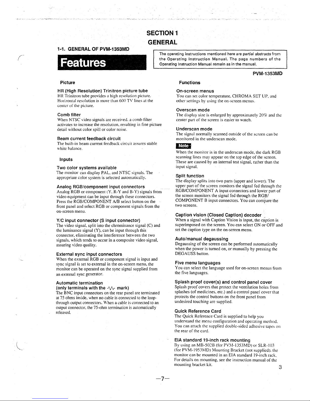
Features
The operating instructions mentioned here are partial abstracts from
the Operating Instruction Manual. The page numbers of the
Operating Instruction Manual remain as in the manual.
Picture
HR (High Resolution) Trinitron picture tube
HR Trinitron tube provides a high resolution picture.
Horizontal resolution is more than 600 TV
lines at the
center of the picture.
Comb filter
When NTSC video signals are received. a comb filter
activates to increase the resolution. resulting in fine picture
detail without color spill or color noise.
Beam current feedback circuit
The built-in beam current feedback circuit assures stable
white balance.
Inputs
Two color systems available
The monitor can display PAL. and NTSC signals. The
appropriate color system is selected automatically.
Analog RGB/component input connectors
Analog RGB or component (Y. R-Y and B-Y) signals from
video equipment can be input through these connectors.
Press the ROB/COMPONENT
A/B select button on the
front panel and select RGB or component signals from the
on-screen menu.
Y/C input connector (S input connector)
The video signal, split into the chrominance signal (C) and
the luminance signal (Y), can be input through this
connector, eliminating the interference
between the two
signals, which tends to occur in a composite video signal,
assuring video quality.
External sync input connectors
When the external RGB or component signal is input and
sync signal is set to external in the on-screen menu, the
monitor can be operated on the sync signal supplied from
an external sync generator.
Automatic termination
(only terminals with the
..1\./v-mark)
The BNC input connectors on the rear panel are terminated
at 75 ohms inside, when no cable is connected to the loopthrough output connectors.
When a cable is connected to an
output connector, the 75-ohm termination is automatically
released.
-7-
PVM-1353MD
Functions
On-screen menus
You can set color temperature. CHROMA SET UP. and
other settings
by using the on-screen menus.
Overscan mode
The display size is enlarged by approximately 20C/c and the
center part of the screen is easier to watch.
Underscan mode
The signal normally scanned outside of the screen can be
monitored in the underscan mode.
IU:Jrl
When the monitor is in the underscan mode, the dark RGB
scanning lines may appear on the top edge of the screen.
These are caused by an internal test signal, rather than the
input signal.
Split function
The display splits into two parts (upper and lower), The
upper part of the screen monitors the signal fed through the
RGB/COMPONENT A input connectors and
lower part of
the screen monitors the signal fed through the RGB/
COMPONENT B input connectors. You can compare the
two screens.
Caption vision (Closed Caption) decoder
When a signal with Caption Vision is input, the ciption is
superimposed on the screen. You can select ON or OFF and
set the caption type on the on-screen menu.
Auto/manual degaussing
Degaussing of the screen can be performed automatically
when the power is turned on, or manually by pressing the
DEGAUSS button.
Five menu languages
You can select the language used for on-screen menus from
the five languages.
Splash proof cover(s) and control panel cover
Splash proof covers that protect the ventilation holes from
splashes (of medicines, etc.) and a control panel cover that
protects the control buttons on the front panel from
undesired touching are supplied.
Quick Reference Card
The Quick Reference Card is supplied to help you
understand the menu configuration and operating method.
You can attach the supplied double-sided adhesive
tape~ on
the rear of the card.
EIA standard 19-inch rack mounting
By using an MB-502B (for PV:.1-l353MDJ or SLR-103
(for PVM-1953~10) Mounting Bracket (not supplied). the
monitor can be mounted in an EIA standard
19-inch rack.
For details on mounting, see the instruction manual of the
mounting bracket kit.
3
·:,/.·-·.•.»."· . .;"
Location and Function of Part~ anti ~~ntrols ·
. ,,.
~ ~
PVM-1353MD
Front Panel . . .
~
00000
.00 000000 o n
L.___Joc~c -co : LJ
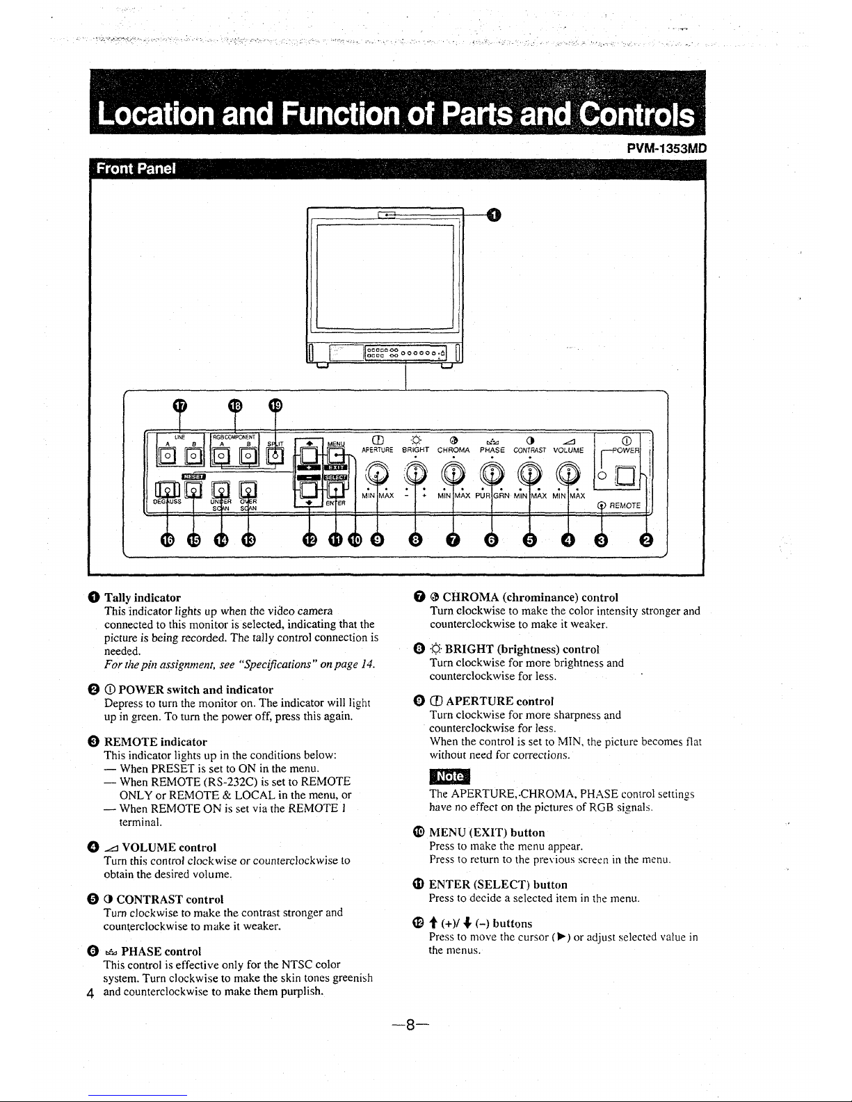
0 Tally indicator
This indicator lights up when the video camera
connected to this monitor is selected, indicating that the
picture is being recorded. The tally control connection is
needed.
For the
pin assignment, see "Specifications" on page 14.
8 CD POWER switch and indicator
Depress to turn the monitor on. The indicator will light
up in green. To turn the power off, press this again.
E) REMOTE indicator
This indicator lights up in the conditions below:
- When PRESET is set to ON in the menu.
- When REMOTE (RS-232C) is set to REMOTE
ONLY or REMOTE
& LOCAL in the menu, or
- When REMOTE ON is set via the REMOTE l
terminal.
0 A VOLUME control
Turn this control clockwise or counterclockwise to
obtain the desired volume.
0 0 CONTRAST control
Turn clockwise to make the contrast stronger and
counterclockwise to make it weaker.
0 .,.,,, PHASE control
This control is effective only for the NTSC color
system. Turn clockwise to make the skin tones greenish
4 and counterclockwise to make them purplish.
-b·
~
,,,:,,, 0 .Ll
SRiciHT CHROMA PHASE CONTRAST VOLUME
REMOTE
0
~
CHROMA (chrominance) control
Turn clockwise to make the color intensity stronger and
counterclockwise to make it weaker.
(l) ·¢.· BRIGHT (brightness) control
Turn clockwise for more brightness and
counterclockwise for less.
0 CD APERTURE control
Turn clockwise for more sharpness and
counterclockwise for Jess.
When the control is set to
MIN. the picture becomes flat
without need for corrections.
,~ma
The APERTURE,-CHROMA, PHASE control settings
have no effect on the pictures of RGB
signals.
~
CI!) MENU (EXIT) button
Press to make the menu appear.
Press to return to the
preYious sere.en in the menu.
~
ENTER (SELECT) button
Press to decide a selected item in the menu.
et(+)/ ,f. (-) buttons
Press to move the cursor (,...) or adjust selected value in
the menus.
-8-
.;,.•.-.~,.,.,: .• · .. , ... •., ;, c•.:•·,·,~··, .• •' •·,.,, ·,·~, ~.·,;•c,··,~.,, ..
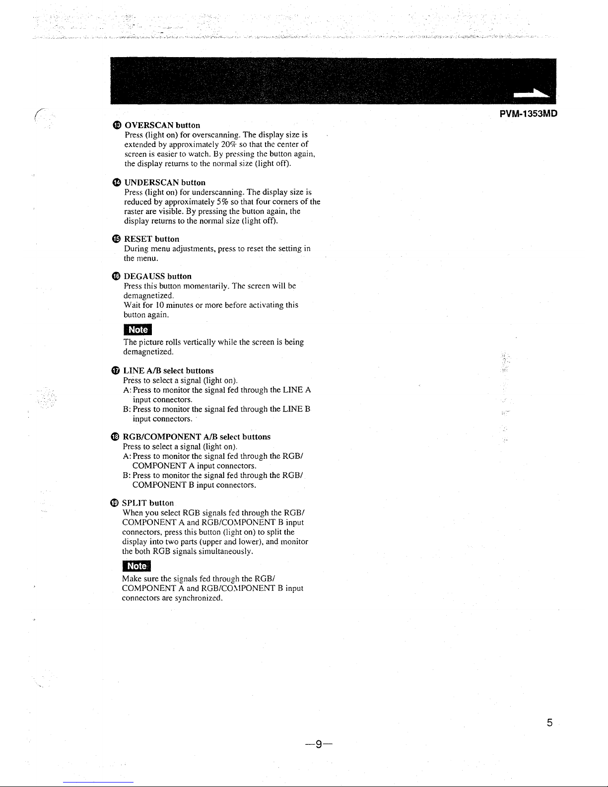
4B OVERSCAN button
Press (light on) for overscanning. The display size is
extended by approximately
20'7c so that the center of
screen is easier to watch. By pressing the button again,
the display returns to the normal size (light oft).
~
UNDERSCAN button
Press (light on) for underscanning. The display size is
reduced by approximately 5% so that four corners of the
raster are visible. By pressing the button again, the
display returns to the normal size {light off).
'9 RESET button
During menu adjustments, press to reset the setting in
the menu.
CD DEGAUSS button
Press this button momentarily. The screen will be
demagnetized.
Wait for IO minutes or more before activating this
button again.
Em?I
The picture rolls vertically while the screen is being
demagnetized.
CD LINE A/B select buttons
Press to select a signal (light on).
A: Press to monitor the signal fed through the LINE A
input connectors.
B: Press to monitor the signal fed through the LINE B
input connectors.
G) RGB/COMPONENT A/B select buttons
Press to select a signal (light on).
A: Press to monitor the signal fed through the RGB/
COMPONENT A input connectors.
B: Press to monitor the signal fed through the RGB/
COMPONENT B input connectors.
~
SPLIT button
When you select RGB signals fed through the RGB/
COMPONENT A and RGB/COMPONENT B input
connectors, press this button (light on) to split the
display into two parts (upper and lower), and monitor
the both RGB signals simultaneously.
mD
Make sure the signals fed through the RGB/
COMPONENT A and RGB/CO.\IPONENT B input
connectors are synchronized.
-9-
PVM-1353MD
5
' '
Location and Function of Parts and Controls
PVM-1353MD
Rear Panel
LINE A
LINE B
VIDEO AUDIO Y/C AUDIO
,--l.!.:IN_,___..;0:::.U:::.T:,.,...l-...:.1:.:,N __ O;::,U;::,T;_, IN OUT IN OUT
©) @@<@)@ @)
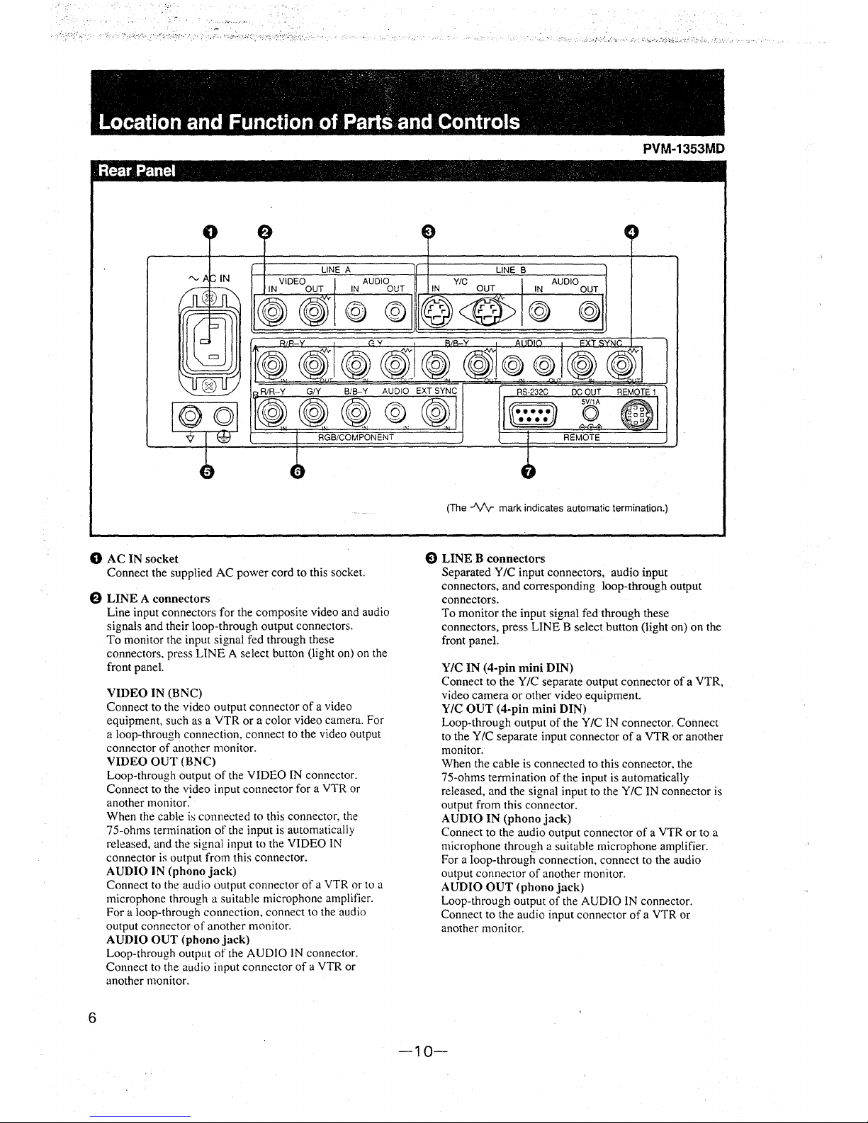
(The -VV mark indicates automatic termination.)
0 AC IN socket
8 LINE B connectors
Connect the supplied AC power cord to this socket.
8 LINE A connectors
6
Line input connectors for the composite video and audio
signals and their loop-through output connectors.
To monitor the input signal fed through these
connectors. press LINE A select button (light on) on the
front paneL
VIDEO IN (BNC)
Connect to the video output connector of a video
equipment, such as a VTR or a color video
camera. For
a loop-through connection, connect to the video output
connector of another
monitor.
VIDEO OUT (BNC)
Loop-through output of the VIDEO IN connector.
Connect to the video input connector for a VTR or
another monitor:
When the cable is connected to this connector, the
75-ohms termination of the input is automatically
released, and the signal input to the VIDEO IN
connector is output from this
connector.
AUDIO IN (phono jack)
Connect to the audio output connector of a VTR or to a
microphone through a suitable microphone
amplifier.
For
a loop-through connection. connect to the audio
output connector of another
monitor.
AUDIO OUT (phonojack)
Loop-through output of the AUDIO IN connector.
Connect to the audio input connector of a VTR or
another monitor.
Separated Y
IC input connectors, audio input
connectors, and corresponding loop-through output
connectors,
To monitor the input signal fed through these
connectors, press LINE B select button (light on) on the
front
panel.
Y/C IN (4-pin mini DIN)
Connect to the Y/C separate output connector of a VTR,
video camera or other video equipment.
Y/C OUT (4-pin mini DIN)
Loop-through output of the Y/C IN connector. Connect
to the Y /C separate input connector of a VTR or another
monitor.
When the cable is connected to this connector. the
75-ohms termination of the input is automatically
released, and the signal input to the
Y/C IN connector is
output from this connector.
AUDIO IN (phono jack)
Connect to the audio output connector of a VTR or to a
microphone through a suitable microphone amplifier.
For a loop-through connection, connect to the audio
output connector of another
monitor.
AUDIO OUT (phono jack)
Loop-through output of the AUDIO IN connector.
Connect to the audio input connector of a VTR or
another
monitor.
-10-
• ~' -
~
~IV , • • • :, ' '
~~
. . .
" ca" •' • ,- ' •
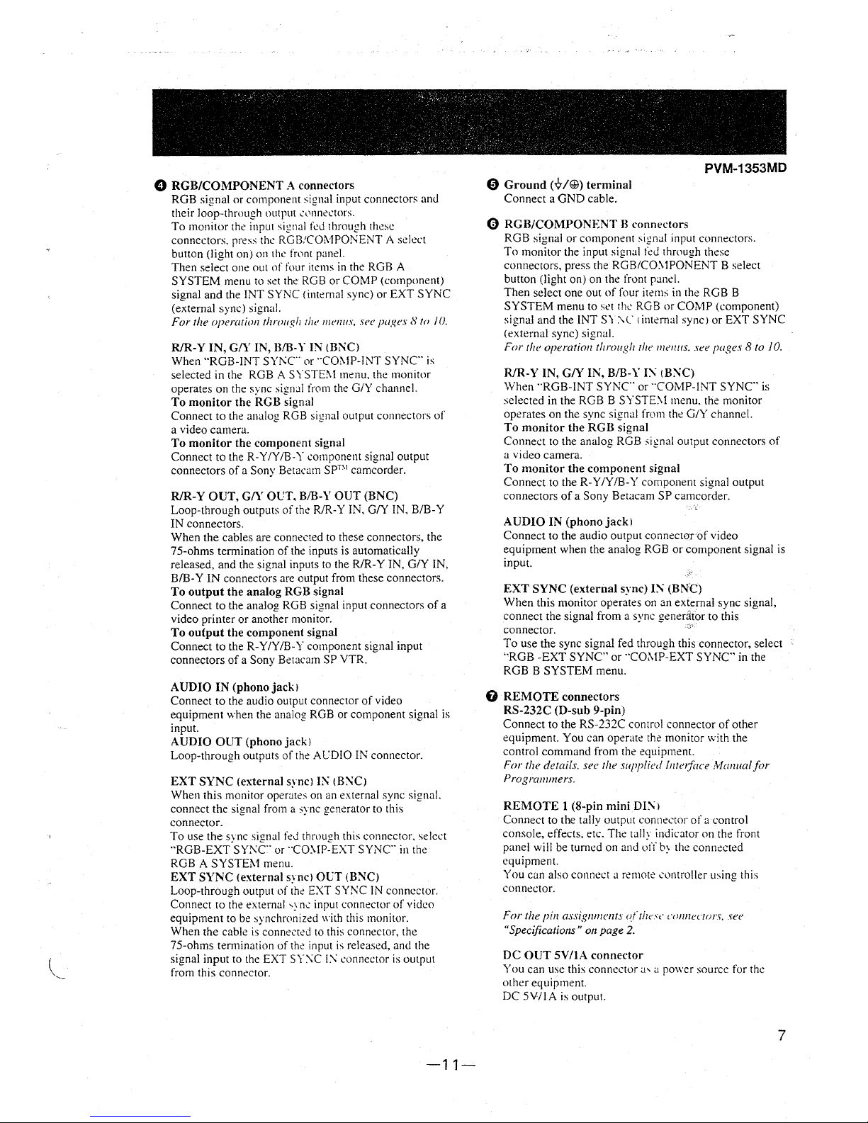
0 RGB/COMPONENT A connectors
RGB signal or component signal input connectors and
their loop-through output ,,,nncctors.
To monitor the input signal fod through these
connectors. press
the RGB!COtv!POJ\iENT A select
button (light on) on the fwnt panel.
Then select one out
of four items in the RGB A
SYSTEM menu to set the RGB or COMP (component)
signal and the INT SYNC (internal sync) or EXT SYNC
(external sync)
signal.
For the operation throuph 1he 111e1111s, Sff pages 8 to /0.
R/R-Y IN, G/Y IN, B/B-Y IN (B;-..;C)
When "ROB-INT SYNC or "CO'.\IP-INT SYNC is
selected
in the RGB A SYSTE'.\I menu. the monitor
operates on the sync
signal from the G/Y channel.
To monitor the RGB signal
Connect to the analog RGB signal output connectors of
a video camera.
To monitor the component signal
Connect to the R-Y /Y /B-Y component signal output
connectors of a Sony
Betacam sprn camcorder.
R/R-Y OUT, G/Y OCT. B/B-Y OUT (BNC)
Loop-through outputs of the R/R-Y IN, G/Y IN, B/B-Y
IN connectors.
When the cables are connected to these connectors, the
75-ohms termination of the inputs is automatically
released, and the signal inputs to the R/R-Y IN, G/Y IN,
BIB-Y IN connectors are output from these connectors.
To output the analog RGB signal
Connect to the analog RGB signal input connectors of a
video printer or another monitor.
To output the component signal
Connect to the R-Y /Y /B-Y component signal input
connectors of a Sony Betacam SP VTR.
AUDIO IN (phonojackJ
Connect to the audio output connector of video
equipment when the analog RGB or component signal is
input.
AUDIO OUT (phonojackJ
Loop-through outputs of the ACDIO IN connector.
EXT SYNC (external sync) I" (B:\'C)
When this monitor operates on an external sync signal.
connect the signal from
a ,ync generator to this
connector.
To use the sync signal fcJ through this connector. select
"RGB-EXT SY;\'C or "CO'.\!P-EXT SYNC in the
RGB A SYSTEM menu.
EXT SYNC (external syncJ OCT (BNC)
Loop-through output of the EXT SY;\'C IN connector.
Connect to the external
,::, nc input connector of video
equipment to be
svnchronized \1·ith this monitor.
When the cable
is' connected to this connector, the
75-ohms ten11i11ation of
the input is released, and the
signal input to the EXT
SY:'\C I.\' connector is output
from this connector.
-11-
PVM-1353MD
0 Ground ('Q'/@) terminal
Connect a GND cable.
0 RGB/COMPONENT B connectors
RGB signal or component
sign.ii input connectors.
To monitor the input signal
fed through these
connectors, press the
RGB/CO'.\IPONENT B select
button (light on) on the front
p.inel.
Then select one out of four items in the ROB B
SYSTEM menu to
st?t the RGB or COMP (component)
sign.ii and the INT SY\C I intern.ii sync) or EXT SYNC
(external sync)
sign.ii.
For the operation through 1he 111e1111s. see pages 8 to JO.
R/R-Y IN, G/Y IN, B/B-Y I:\ (BNC)
When ··RGB-INT SYNC or "COMP-INT SYNC" is
selected in the RGB B
SYSTE'.\I menu. the monitor
operates on the sync signal from the G/Y channel.
To monitor the RGB signal
Connect to the analog RGB signal output connectors of
a video camera.
To monitor the component signal
Connect to the R-Y /Y /B-Y component signal output
connectors of a Sony Betacam SP camcorder.
AUDIO IN (phonojackl
Connect to the audio output connector of video
equipment when the analog RGB or component signal is
input.
EXT SYNC (external sync) IN (BNC)
When this monitor operates on an external sync signal,
connect the signal from a sync
genertlior to this
connector.
To use the sync signal fed through this connector, select
"RGB -EXT SYNC" or "C0:-.1P-EXT SYNC in the
RGB B SYSTEM menu.
0 REMOTE connectors
RS-232C (D-sub 9-pin)
Connect to the RS-232C control connector of other
equipment. You can
operate the monitor with the
control command from the equipment.
For the details. see the supplied lntuface :'v!anua! for
Programmers.
REMOTE 1 (8-pin mini DI:\l
Connect to the tally output connector of a control
console, effects. etc.
The tally indicator 011 the front
panel will be turned on and
off b:-the connected
equipment.
You can also connect
a remote controller using this
connector.
For the pin assig11111enTs <f Thc·s,· n,nneuors, see
"Specifications" on page 2.
DC OUT SV/IA connector
You can use this connector .i, .i power source for the
other equipment.
DC 5V/IA is output.
7
PVM-1353MD
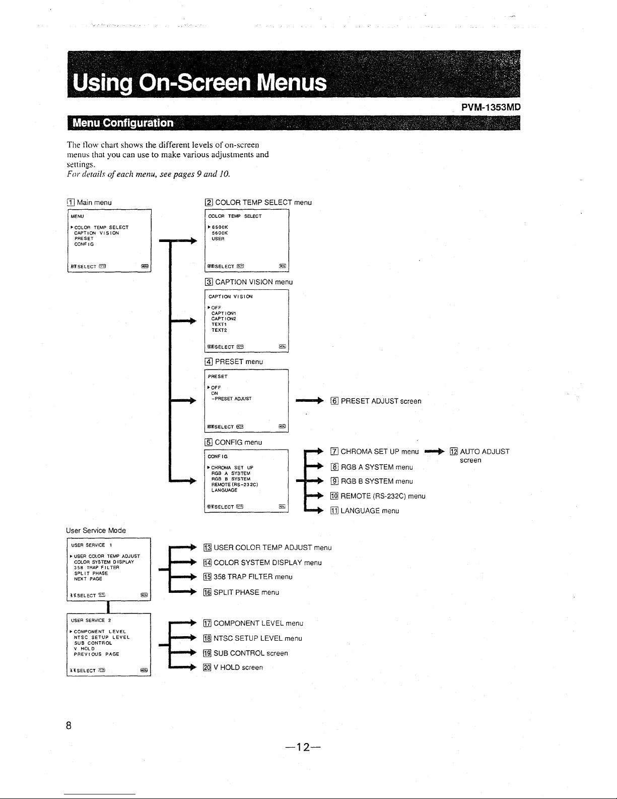
Menu Configuration ,. · · -, "· -. , · , ., '\ · - -. _ -:" ,, :'
The flow chart shows the different levels of on-screen
menus
that you can use to make various adjustments and
settings.
For details of each menu, see pages 9 and JO.
[] Main menu [g) COLOR TEMP SELECT menu
MENU
"'COLOR TEMP SELECT
CAPTI0/'11 VISION
PRESET
CONF
IG
IIISELECT iB
COLOR TEMP SELECT
"'6500K
5600K
USER
!I(f)SELECT fE3
@l CAPTION VISION menu
CAPTION VISION
J>QFF
CAPTION1
CAPTION2
TEXT1
TEXT2
!m!SELECT 0
@] PRESET menu
PRESET
•OFF
ON
- PRESET ADJUST
IIHJSELECT @I
[ID CONFIG menu
--+ [§] PRESET ADJUST screen
CONF IG
II] CHROMA SET UP menu ...... fill AUTO ADJUST
User Service Mode
USER SERVICE 1
"'USER COLOR TEMP ADJUST
COLOR SYSTEM DI SPLAY
358
TRAP FILTER
SPLIT PHASE
NEXT PAGE
l:fSELECT 'ES
I
USER SERVICE 2
"'COMPONENT LEVEL
NTSC SETUP LEVEL
SUB CONTROL
V
HOLD
PREVIOUS PAGE
llSELECT §
8
~
@
• CHROMA SET UP
RGB
A SYSTEM
RGB 8 SYSTEM
REMOTE (AS-23 2C)
LANGUAGE
f!!TSELECT 0
ffiJ RGB A SYSTEM menu
[[] RGB B SYSTEM menu
[Q] REMOTE (RS-232C) menu
ID] LANGUAGE menu
~
USER COLOR TEMP ADJUST menu
MJ COLOR SYSTEM DISPLAY menu
[§I 358 TRAP FILTER menu
[§j SPLIT PHASE menu
[ZJ COMPONENT LEVEL menu
11]] NTSC SETUP LEVEL menu
jill SUB CONTROL screen
[gQ] V HOLD screen
-12-
screen
, .. \?-r., ·'·-!F~>_. . .. · . · .. t,/·· .. - .
:
~
, :,,'
~
"' /." < ·,. • '
~
. -
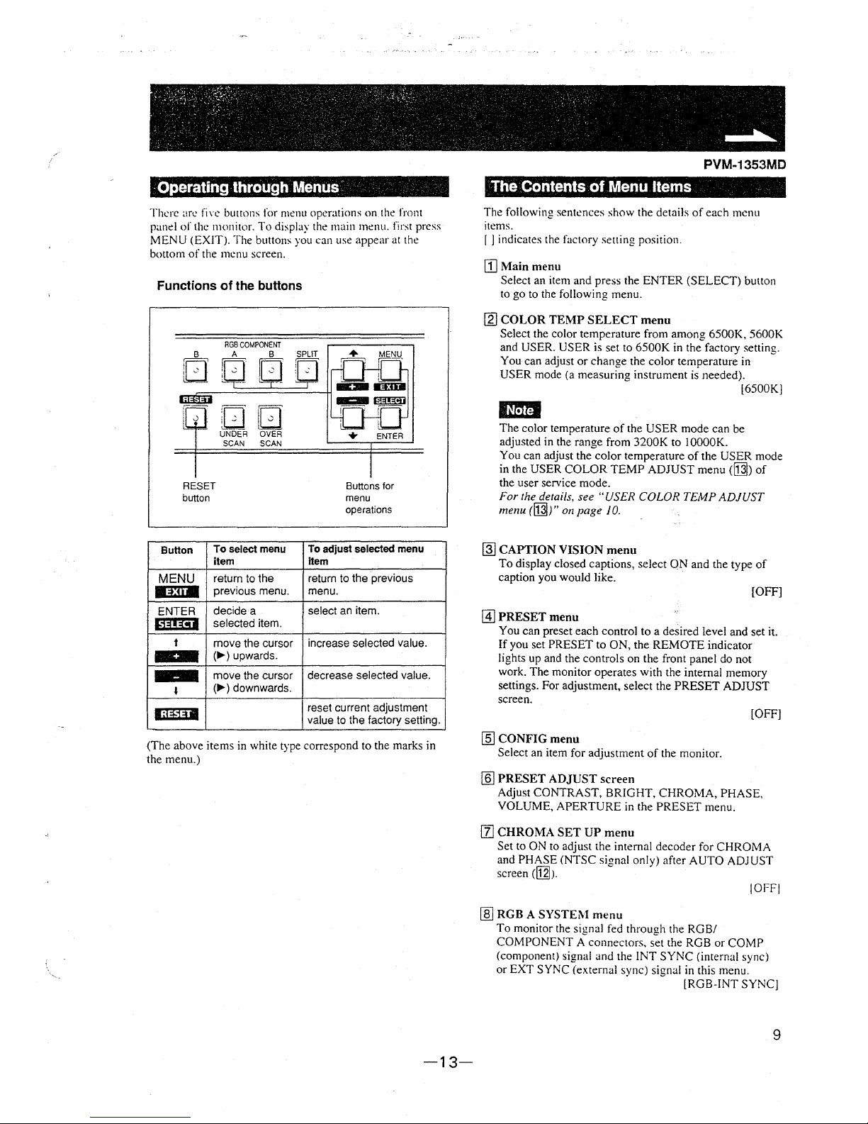
· Operating through Menus·
There are fin: buttons for menu operations on the front
panel of the monitor. To display the main menu. first press
MENU (EXIT). The buttons you can use appear at the
bottom of the menu screen.
Functions of the buttons
RGB COMPONENT
B A B SPLIT
nu GD
lLJ L_7___ =r--;_
DD
UNDER OVER
SCAN SCAN
RESET
button
Button
To select menu
item
MENU
return to the
11~:1111
previous menu.
ENTER
decide a
l1~!!~1
selected item.
t
move the cursor
(..,._) upwards.
move the cursor
•
(..,._) downwards .
liiil~I
Buttons for
menu
operations
To adjust selected menu
Item
return to the previous
menu.
select an item.
increase selected value.
decrease selected value.
reset current adjustment
value to the factory setting.
(The above items in white type correspond to the marks in
the menu.)
-13-
PVM-1353MD
The Contents of Menu Items
The following sentences show the details of each menu
items.
r J indicates the factory setting position.
[]Main menu
Select an item and press the ENTER (SELECT) button
to go to the following menu.
[g:j COLOR TEMP SELECT menu
Select the color temperature from among 6500K, 5600K
and USER. USER is set to 6500K in the factory setting.
You can adjust or change the color temperature in
USER mode (a measuring instrument is needed).
[6500K]
IMUI
The color temperature of the USER mode can be
adjusted in the range from
3200K to I OOOOK.
You can adjust the color temperature of the USER mode
in the USER COLOR TEMP ADJUST menu
(M) of
the user service mode.
For the details, see "USER COLOR TEMP ADJUST
menu (M)" on page 10.
~
CAPTION VISION menu
To display closed captions, select ON and the type of
caption you would like.
[OFF]
@] PRESET menu
You can preset each control to a desired level and set it.
If you set PRESET to ON, the REMOTE indicator
lights up and the controls on the front panel do not
work. The monitor operates with the internal memory
settings. For adjustment, select the PRESET ADJUST
screen.
[OFF]
[§] CONFIG menu
Select an item for adjustment of the monitor.
[§] PRESET ADJUST screen
Adjust CONTRAST, BRIGHT, CHROMA, PHASE,
VOLUME, APERTURE in the PRESET menu.
[I] CHROMA SET UP menu
Set to ON to adjust the internal decoder for CHROMA
and PHASE (NTSC signal only) after AUTO ADJUST
screen
([j]J.
!OFFJ
ffi] RGB A SYSTEl\I menu
To monitor the signal fed through the RGB/
COMPONENT A connectors. set the RGB or COMP
(component) signal and the INT SYNC (internal sync)
or EXT SYNC (external sync) signal in this menu.
[RGB-lNT SYNC]
9

. :i . . ,{,,: . .. t:t~rt ; ;,, s)f;,
Using On-Screen ·Menus _; __ .-._:·:·. ·· --: :: · ..
[ill RGB B SYSTEM menu
To monitor the signal fed through the RGB/
COMPONENT B connectors, set
the RGB or COMP
(component) signal and
the INT SYNC (internal sync)
or EXT SYNC (external sync) signal in this menu.
IRGB-INT SYNC!
[ill REMOTE (RS-232C) menu
Select one out of following three modes.
REMOTE OFF:
You can adjust settings and controls by the buttons and
controls on the front panel.
RS-232C connector does not function.
REMOTE ONLY:
You can adjust settings and controls through the
RS-232C connector.
Buttons and controls on the front panel. except the
menu operation ones, do not function.
REMOTE & LOCAL:
You can adjust settings and controls both through the
RS-232C connector and the front panel buttons.
Controls on the front panel do not function.
[REMOTE OFF]
B] LANGUAGE menu
You can select the language used for on-screen menus
from the following five languages (English,
German,
French, Italian, Spanish).
[ENGLISH]
[gj AUTO ADJUST screen
Select the color bar signal (full, SMPTE, EIA) and press
the ENTER (SELECT) button to start automatic
adjustment.for CHROMA and PHASE. For these
adjustments
io be valid, you must select ON in
CHROMA SET UP menu
([I]).
User Service Mode
The user service mode is useful when adjusting the settings
and controls except for the above.
To enter the user service mode, press and hold the MENU
(EXIT) button until the following USER SERVICE I
appears.
To move to the second page of the mode. select
''NEXT
PAGE"
and to return to the first page of the menu, select
"PREVIOUS
PAGE".
10
USER SERVICE 1
,. USER COLOR TEMP ADJUST
COLOR SYSTEM O I SPLAY
358 TRAP FILTER
SPLIT PHASE
NEXT PAGE
!if SELECT@
USER SERVICE 2
i,, COMPONENT LEVEL
NTSC SETUP LEVEL
SUB CONTROL
V HOLD
PREVIOUS PAGE
:u SELECT '::::·:
PVM-1353MD
~
USER COLOR TEMP ADJUST menu
The value of adjustment in this menu works only when
"USER" is selected in the COLOR TDIP SELECT
menu ([1] ).
ADJUST GAIN:
Adjusts
the color balance (gain) of the USER mode.
ADJUST BIAS:
Adjusts the color balance (bias) of the USER mode.
COLOR TEMP RANGE:
When you adjust the color temperature in the USER
mode. select a color temperature range before
adjusting ADJUST GAIN
and ADJUST BIAS. If the
adjusted color temperature is between 3200K and
5000K. select
"3200K-5000K." If the adju,ted color
temperature is between 5000K and lOOOOK.
select
"5000K-IOOOOK." [5000K-10000K]
[11 COLOR SYSTEM DISPLAY menu
Select the color system display mode. In Al'TO. the
kind of color system being used appears on the screen
each time you change the signal input. [AUTO]
!1]1358 TRAP FILTER menu
Color spill or color noise may be eliminated if you
select ON (NTSC signal only). Normally set it to OFF.
[OFF]
[§I SPLIT PHASE menu
When the SPLIT function is activated, if the lower side
picture (the signal fed through the RGB/COMPONENT
B input connectors) has some discrepancy of location
with the upper side picture, adjust the SPLIT PHASE
menu.
Each time you press the
t( +) button. the lower side
picture moves left.
IUMI
When the adjustment is made in the menu. the skew
error will occur on the top of the lower side picture.
Bl] COMPONENT LEVEL menu
Select the component level from among three modes.
NIO/SMPTE: for 100/0/100/0 signal
BETA 7.5: for 100/7.5/75/7.5 signal
BET A 0: for l 00/0/75/0 signal (BETA 7.5]
[j]J NTSC SETUP LEVEL menu
Select the NTSC setup level from two modes. The 7.5
setup level is mainly used in north America. The O setup
level is mainly used in Japan. [7.5)
G]J SUB CONTROL screen
You can finely adjust the controls on the front panel.
CONTRAST. PHASE,
CHR01'-IA and BRIGHT
controls
have clicks at the center of their adju,tment
range. You can adjust the setting of the click
po~ition
with this feature.
[gQ] V HOLD screen
Adjust the vertical hold if the picture rolls \enically.
IUtitl
If the rolling of the picture prevents you from watching
the screen. select an input that has nothing connected.
-14-

(
. ' '- . . ',- ': ' . '~" ·:,.
~
Power Sources -·, -->
PVM-1353MD
House Current ·
Connect the supplied AC power cord to the AC IN socket
on
the rear panel and to a wall outlet.
to a wall outlet
========= ....
To connect an AC power cord securely with the AC plug holder
1 AC IN socket
Plug the power cord into the AC IN socket. Then, attach
the AC plug holder (supplied) on top of the AC power
cord.
To remove the AC power cord
Pull out AC plug holder by squeezing the up and down sides.
-15-
2
Slide the AC plug holder over the cord until it connects
with the attached
holder.
11
' ' '~ • - • >; :- ' '> ~: :-~·,._ >
~
<
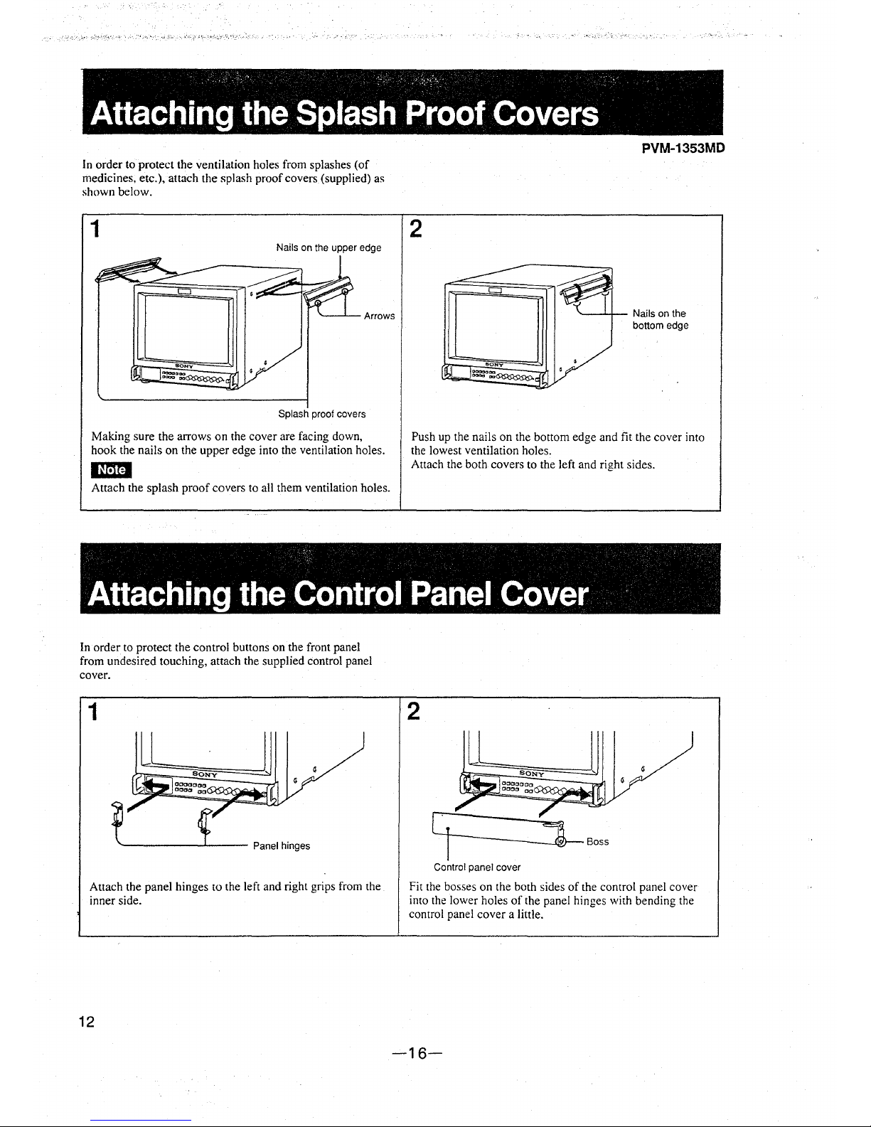
Attaching the Splash Proof Covers
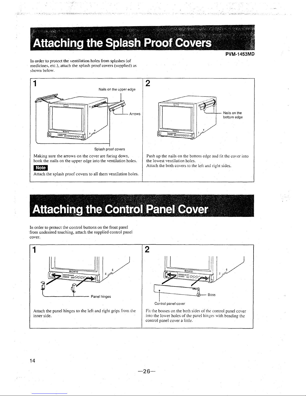
In order to protect the ventilation holes from splashes (of
medicines, etc.), attach the splash proof covers (supplied) as
shown below.
1
Nails on the upper edge
Splash proof covers
Making sure the arrows on the cover are facing down,
hook the nails on the upper edge into the ventilation holes.
Em
Attach the splash proof covers to all them ventilation holes.
2
PVM-1353MD
"----'-+-- Nails on the
bottom edge
Push up the nails on the bottom edge and fit the cover into
the lowest ventilation holes.
Attach the both covers to the left and right sides.
Attaching the Control Panel Cover ·
In order to protect the control buttons on the front panel
from undesired touching, attach the supplied control panel
cover.
1
~---------'---- Panel hinges
Attach the panel hinges to the left and right grips from the
inner side.
12
2
Control panel cover
Fit the bosses on the both sides of the control panel cover
into the lower holes of the panel hinges with bending the
control panel cover a little.
-16-
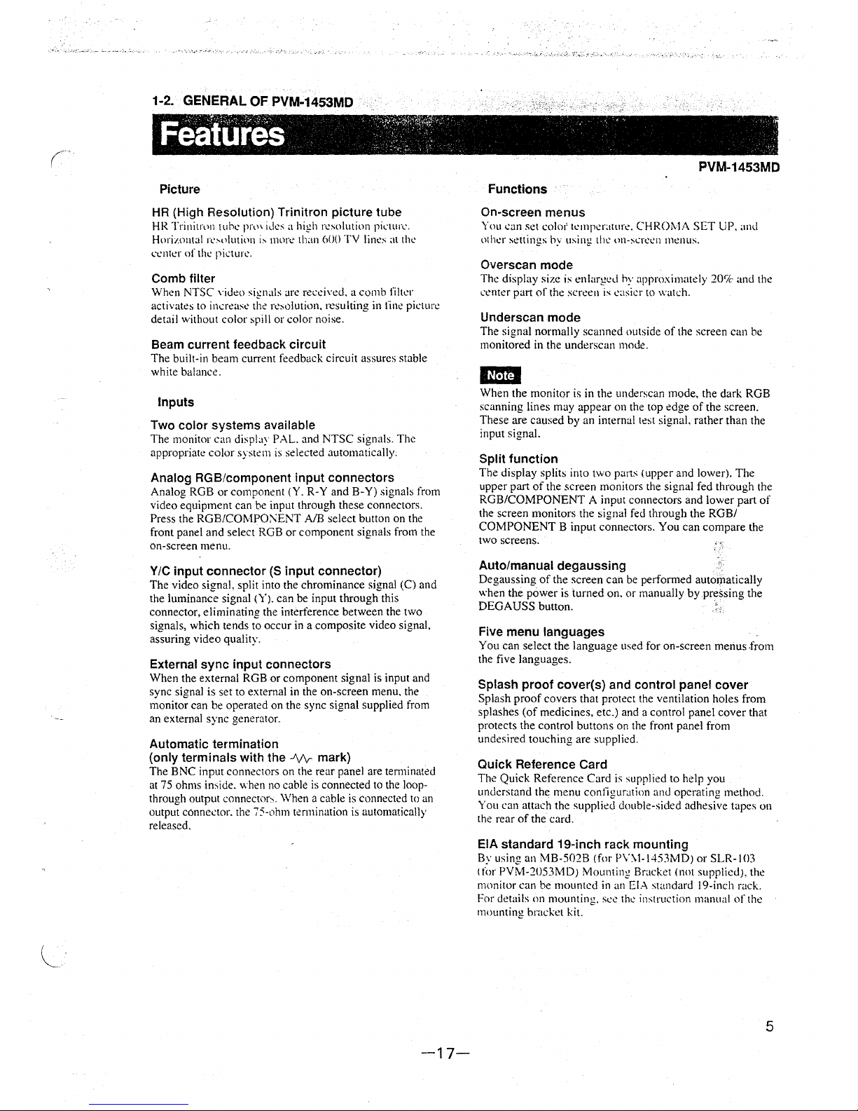
1-2. GENERAL OF PVM-1453MD
Picture
HR (High Resolution) Trinitron picture tube
HR Trinitrt>n tub.: pr,n id.:s a high r.:solution piL·wrc.
Horimntal I\',,>luti,,n i, rnon: than 600
TV lin.:s al th.:
c.:nll:r of
the picturl'.
Comb filter
When NTSC \·ideo sirnals arc rect:i\'ed. a comb filter
activates to increase tl1e re,olution. resulting in fine picture
detail without color spill or color noise.
Beam current feedback circuit
The built-in beam current feedback circuit assures stable
white balance.
Inputs
Two color systems available
The monitor can display PAL. and NTSC signals. The
appropriate color system is selected automatically.
Analog RGB/component input connectors
Analog RGB or component (Y. R-Y and B-Y) signals from
video equipment can be input through these connectors.
Press the RGB/COMPO:\ENT
AIB select button on the
front panel and select RGB or component signals from the
on-screen menu.
Y/C input connector (S input connector)
The video signal, split into the chrominance signal (C) and
the luminance signal
(Y). can be input through this
connector, eliminating the interference between the two
signals, which tends to occur in a composite video signal,
assuring video quality.
External sync input connectors
When the external RGB or component signal is input and
sync signal is set to external in the on-screen menu, the
monitor can be operated on the sync signal supplied from
an external sync generator.
Automatic termination
(only terminals with the
-'Vv-mark)
The BNC input connectors on the rear panel are tem1inated
at 75 ohms in,ide.
when no cable is connected to the loop-
through output
connecwr,. When a cable is connected to an
output connector. the
75-ohm termination is automatically
released.
-17-
PVM-1453MD
Functions
On-screen menus
You can set colo1' t.:rnperatur<:. CHROMA SET UP, and
oth,:r
settings hy using till' on-scr.:.:11 menus.
Overscan mode
Th.: display size is enlarged by approximately 20'7c and the
L'Cnter pal1 of the scr.:en is .:asit:r to watch.
Underscan mode
The signal normally scanned outside of the screen can be
monitored in the underscan mode.
'*"'
When the monitor is in the underscan mode, the dark RGB
scanning lines may appear on the top edge of the screen.
These are caused by an internal test signal. rather than the
input signal.
Split function
The display splits into two pans (upper and lower). The
upper part of the screen monitors the signal fed through the
RGB/COMPONENT A input connectors and lower part of
the screen monitors the signal fed through the RGB/
COMPONENT B input connectors. You can compare the
two screens.
Auto/manual degaussing
Degaussing of the screen can be performed auto1J1atically
when the power is turned on. or manually by pressing the
DEGAUSS button.
Five menu languages .
You can select the language used for on-screen menus .from
the five languages.
Splash proof cover(s) and control panel cover
Splash proof covers that protect the ventilation holes from
splashes (of medicines, etc.) and a control panel cover that
protects the control buttons on the front panel from
undesired touching are supplied.
Quick Reference Card
The Quick Reference Card is supplied to help you
understand the menu configuration
and operating method.
You can attach the supplied double-sided adhesive tapes on
the rear of the card.
.
EIA standard 19-inch rack mounting
By using an MB-502B (for P\'\l-1453MD) or SLR-103
t for PVM-2053MD) Mounting Bracket (not supplied), the
monitor can be mounted in
an El..\ standard 19-inch rack.
For details on mounting. see th.: instruction manual of the
mounting
bracket kit.
5
PVM-1453MD
~
00000
;00000000 o n
~0000 '00 : u
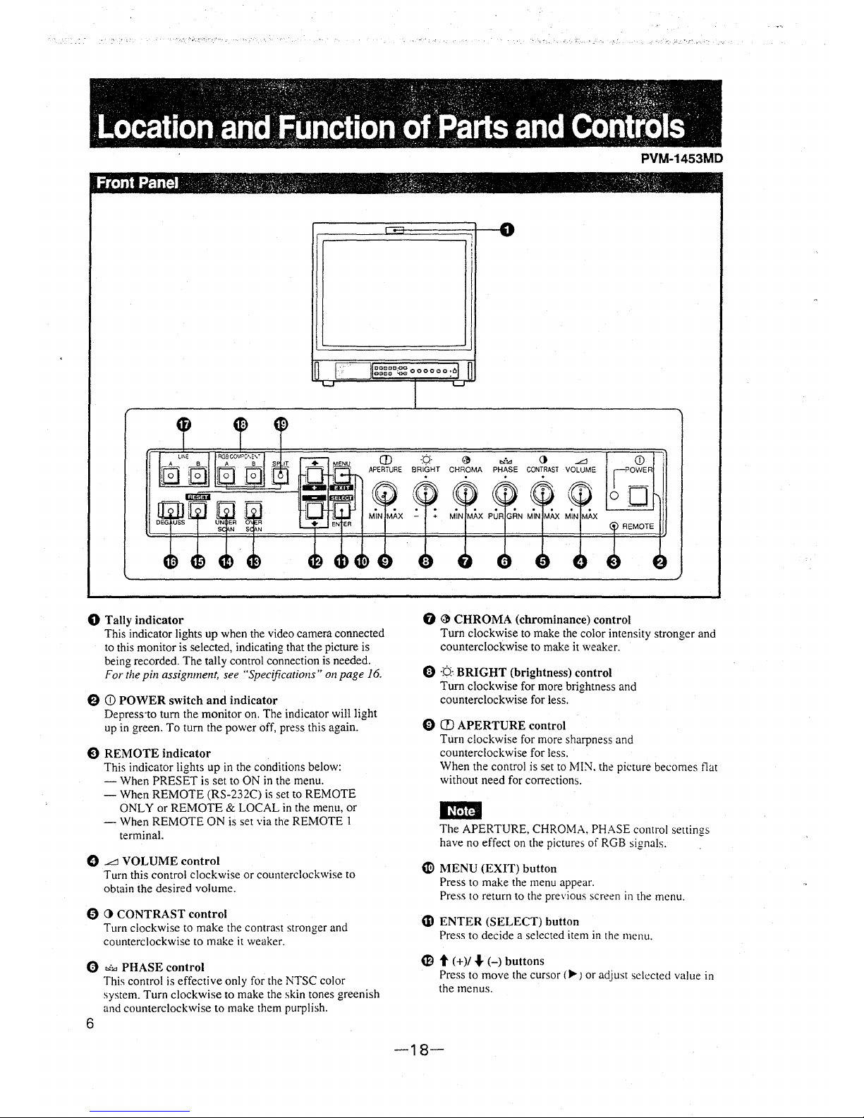
0 Tally indicator
This indicator lights up when the video camera connected
to this monitor is selected, indicating that the picture is
being recorded. The tally control connection is needed.
For the pin assignment, see "Specifications" on page 16.
8 CD POWER switch and indicator
Depress·to tum the monitor on. The indicator will light
up in green. To turn the power off, press this again.
E) REMOTE indicator
This indicator lights up in the conditions below:
- When PRESET is set to ON in the menu.
- When REMOTE (RS-232C) is set to REMOTE
ONLY or REMOTE
& LOCAL in the menu, or
- When REMOTE ON is set via the REMOTE I
terminal.
0 L'.l VOLUME control
Turn this control clockwise or counterclockwise to
obtain the desired volume.
0 (} CONTRAST control
Turn clockwise to make the contrast stronger and
counterclockwise to make it weaker.
0 ""."' PHASE control
6
This control is effective only for the NTSC color
system. Turn clockwise to make the skin tones greenish
and counterclockwise to make them purplish.
0 "'"' 0 .L:J
CHROMA PHASE CONTRAST VOLUME
REMOTE
G
~
CHROMA (chrominance) control
Turn clockwise to make the color intensity stronger and
counterclockwise to make it weaker.
8 ·¢.· BRIGHT (brightness) control
Turn clockwise for more brightness and
counterclockwise for less.
0 CD APERTURE control
Turn clockwise for more sharpness and
counterclockwise for less.
When the control is set to
MIN. the picture becomes flat
without need for corrections.
IHfiti
The APERTURE, CHROMA. PHASE control settirnis
have no effect on the pictures of RGB signals.
~
e MENU (EXIT) button
Press to make the menu appear.
Press to return to the previous screen in the menu.
(D ENTER (SELECT) button
Press to decide a selected item in the menu.
CB t (+)/ ... (-)buttons
Press to move the cursor (Iii-J or adjust selected value in
the menus.
-18-
;
I
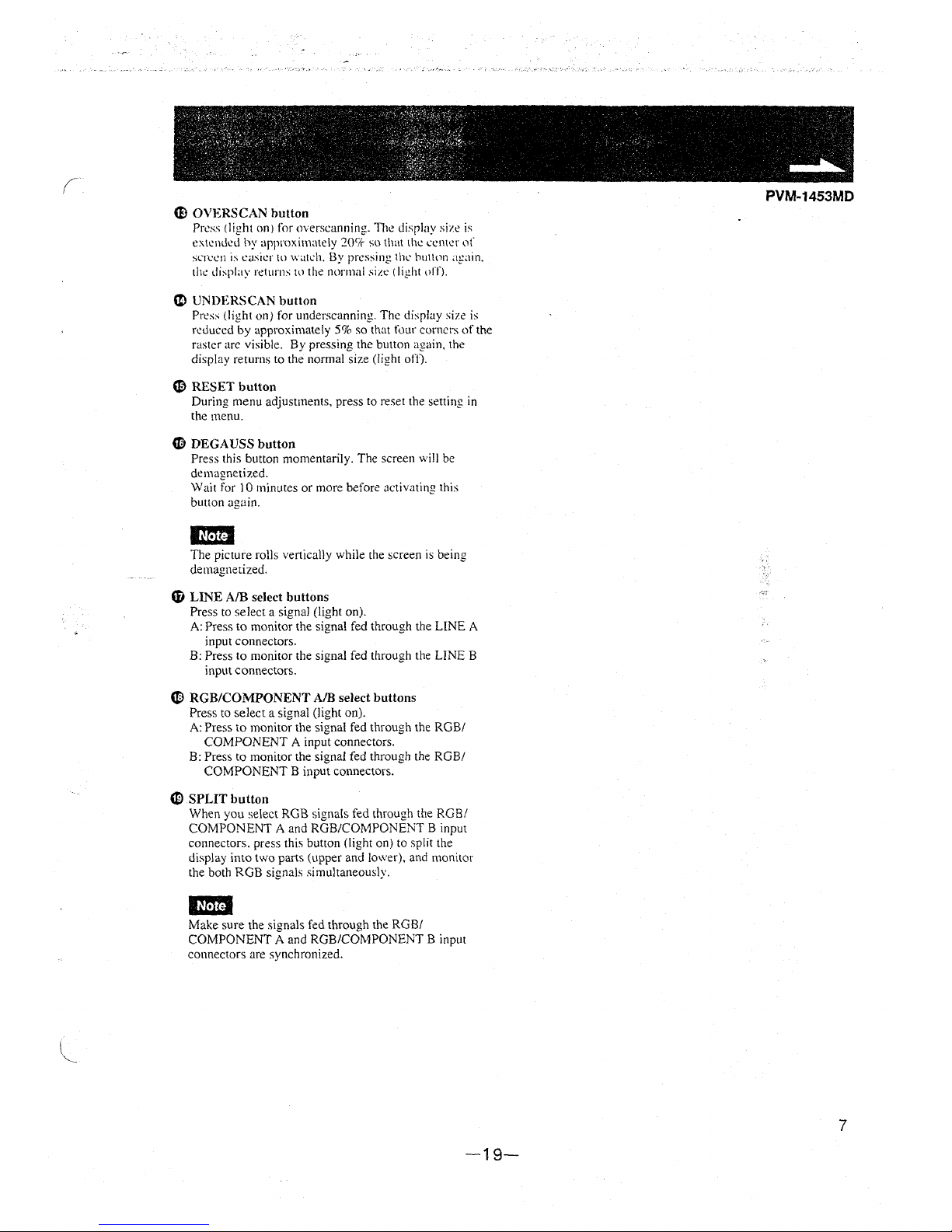
CF) OVERSCAN button
Press (light on) for overscanning. The disrlay size is
extemkd by approximately 2oc1c so that th<.: cel1\n ,)f
screen is easier to w,itch. By pressing the' bullon af,lin.
the display returns Ill the normal size ( light \lff}.
CI) UNDERSCAN button
Press {light on} for underscanning. The display size is
reduced by approximately 5% so that four corners of the
raster arc visible.
By pressing the button again, the
display returns to the normal size (light
off).
C9 RESET button
During menu adjustments, press to reset the setting in
the menu.
CB DEGAUSS button
Press this button momentarily. The screen will be
demagnetized.
Wait for 10 minutes or more before
activating this
button again.
en
The picture rolls vertically while the screen is being
demagnetized.
G) LINE A/B select buttons
Press to select a signal (light on).
A: Press to monitor the signal fed through the LINE A
input connectors.
B: Press to monitor the signal fed through the LINE B
input connectors.
(Ill RGB/COMPONENT A/B select buttons
Press to select a signal (light on).
A: Press to monitor the signal fed through the RGB/
COMPONENT A input connectors.
B: Press to monitor the signal fed through the RGB/
COMPONENT B input connectors.
'1J) SPLIT button
When you select RGB signals fed through the RGB/
COMPONENT A and RGB/COMPONENT B input
connectors. press this button (light on) to split the
display into two parts (upper and lower), and monitor
the both RGB signals simultaneously.
m
Make sure the signals fed through the RGB/
COMPONENT A and RGB/COMPONENT B input
connectors are synchronized.
-19-
PVM-1453MD
7
e
0
I
PVM-1453MD
l-l-----'L='-1:..:NE=-:.A.:.__A_U_D_IO--r~~ C LINE B
AUDIO
OUT
IN OUT IN
OUT
I
0
Im
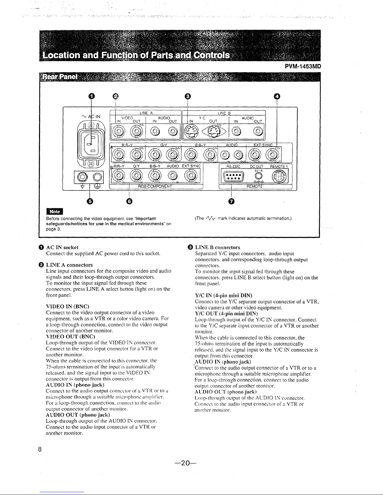
Before connecting the video equipment. see ·'Important
safeguards/notices for use in the medical environments"
on
page 3.
0 AC IN socket
Connect the supplied AC power cord to this socket.
8 LINE A connectors
8
Line input connectors for the composite video and audio
signals and their loop-through output connectors.
To monitor the
input signal fed through these
connectors. press
LINE A select button (light on) on the
front panel.
VIDEO IN (BNC)
Connect to the video output connector of a video
equipment. such as a VTR or a color
video camera. For
a loop-through connection. connect to the video output
connector of another monitor.
VIDEO OUT (BNC)
Loop-through output of the VIDEO l:\l connector.
Connect to the video input connector for a VTR or
another monitor.
When the cable is connected to this connector. the
75-ohms termination of the input is automatically
released. and the signal input to the VIDEO Ii\
connector is output from this connector.
ACDIO IN (phonojack)
Connect to the audio output connector of a VTR or to a
microphone through a
suitable microphone amplifier.
For a loop-through connection. connect to the audio
output connector of another monitor.
AUDIO OUT (phonojack)
Loop-through output of the AUDIO 1:\: connector.
Connect to the audio input
conncctlll' of a VTR or
another monitor.
@<@)
0
(The -'V\r mark indicates automatic termination.)
0 LINE B connectors
Separated Y /C input connectors, audio input
connectors. and corresponding loop-through output
connectors.
To monitor the input signal fed through these
connectors. press
LINE B select button (light on) on the
front panel.
Y/C IN (4-pin mini DIN)
Connect to the Y/C separate output connector of a VTR.
video camera or other video equipment.
Y/C OUT (4-pin mini DIN)
Loop-through output of the Y /C IN connector. Connect
to the Y/C separate input connector of a VTR or another
monitor.
When
the cable is connected to this connector, the
75-ohrns termination of the input is automatically
relea\ed. and the signal input to the Y/C IN connector is
output from this connector.
AUDIO Il\ (phonojack)
·connect to the audio output connector of a VTR or to a
microphone through a suitable microphone amplifier.
For a loop-through connection. connect to the audio
output connector of another monitor.
ACDIO OLT (phono jack)
Lollp-through output of the ALDIO l:'\ connector.
Connect
w the audio input connector of a VTR or
another monitor.
-20-

(
""-·
0 RGB/COMPONENT A connectors
RGB signal or component signal input connectors and
their loop-through output connectors.
To monitor the input signal fed through these
connectors. press
the RGB/COMPONE;-,iT A select
button (light on) on the front panel.
Then
select one out of four items in the RGB A
SYSTEM menu to set the RGB or COMP (component)
signal and the INT SYNC (internal sync) or EXT SYNC
(external sync) signal.
For the operation through the menus. see pages 10 to
12.
R/R-Y IN, G/Y IN, B/B-Y IN (BNC)
When .. RGB-INT SYNC or .. COMP-INT SYNC" is
selected in the RGB
A SYSTEM menu, the monitor
operates on the sync signal from the G/Y channel.
To monitor the RGB signal
Connect to the analog RGB signal output connectors of
a video camera.
To monitor the component signal
Connect to the R-Y /Y /B- Y component signal output
connectors of a Sony Betacam
SPTM camcorder.
R/R-Y OUT, G/Y OUT, B/B-Y OUT (BNC)
Loop-through outputs of the R/R-Y IN, G/Y IN, B/B-Y
IN connectors.
When the cables are connected to these connectors, the
75-ohms termination of the inputs is automatically
released, and the signal inputs to the R/R-Y
IN, G/Y IN,
BIB-Y IN connectors are output from these connectors.
To output the analog RGB signal
Connect to the analog RGB signal input connectors of a
video printer or another monitor.
To output the component signal
Connect to the R-Y /Y /B- Y component signal input
connectors of a Sony Betacam SP VTR.
AUDIO IN (phono jack)
Connect to the audio output connector of video
equipment
when the analog RGB or component signal is
input.
AUDIO OUT (phono jack)
Loop-through outputs of the AUDIO I~ connector.
EXT SYNC (external sync! IN (BNCJ
When this monitor operates on an external sync signal,
connect the signal from a
sync generator to this
connector.
To use the sync signal fed through this connector, select
.. RGB-EXT SYNC or .. CO'.\IP-EXT SYNC in the
RGB
A SYSTEM menu.
EXT SYNC (external sync) OUT (B:\C)
Loop-through output of the EXT
SYNC IN connector.
Connect to the external sync input connector of video
equipment to be synchronized
with this monitor.
When the cable is connected to this connector, the
75-ohms
termination of the input is released. and the
signal input to the EXT SY'.\C IN connector is output
from this connector.
-21-
PVM-1453MD
0 Ground ('17/@) terminal
Connect a GND cable.
0 RGB/COMPONENT B connectors
RGB signal or component
signal input connectors.
To monitor the input signal
fed through these
connectors, press the RGB/COMPONENT B select
button
(I ight on) on the front panel.
Then select one out of four items in the RGB B
SYSTEM menu to set the RGB or COMP (component)
signal and the INT SYNC (internal sync) or EXT SYNC
(external sync) signal.
For the operation through the menus, see pages JO to
12.
R/R-Y IN, G/Y IN, B/B-Y IN (BNC)
When "RGB-INT SYNC" or "COMP-INT SYNC" is
selected in the RGB B SYSTEM menu, the monitor
operates on the sync signal from the
G/Y channel.
To monitor the RGB signal
Connect to the analog RGB signal output connectors of
a video camera.
To monitor the component signal
Connect to the R-Y /Y /B-Y component signal output
connectors of a Sony Betacam SP car11corder.
AUDIO IN (phono jack)
Connect to the audio output connector of video
equipment when the analog RGB or component signal is
input.
EXT SYNC (external sync) IN (BNC)
When this monitor operates on an external sync signal,
connect the signal from a sync generator to this
connector.
To use the sync signal fed through this connector, select
"RGB -EXT SYNC" or "COMP-EXT SYNC" in the
RGB B SYSTEM menu.
0 REMOTE connectors
RS-232C (D-sub 9-pin)
Connect to the RS-232C control connector of other
equipment. You can operate the monitor with the
control command from the equipment.
For the details, see the supplied lnte1face Manual for
Programmers.
REMOTE 1 (8-pin mini DIN)
Connect to the tally output connector of a control
console. effects, etc. The tally indicator on the
fro~t
panel will be turned on and off by the connected
equipment.
You can also connect a remote controller using this
connector.
For the pin assig11111ellts of these co1111ectors. see
"Specifications" on page 4.
DC OUT SV /lA connector
You can use this connector as a power source for the
other equipment.
DC 5V
/I A is output.
9
. ,,_
-~.,;.:/ .·. _·, '~ ' . ' ., .. -~::··,\. ',:•,/>.~-<\. r • ', '· •.' • • ,:,S', 1 . _,' . :, ·\','N-'3:\:'.·'· ;' _,,;·' .,:·~:,;;~;~~;_?• y:r;,;
'.~o·sing· On~Screen'"·M.en·us· ,,.;.. . .. ... . ~,,J,,,,w.,h·, .• , .• ---~·~Jt ·· -?~'./~i
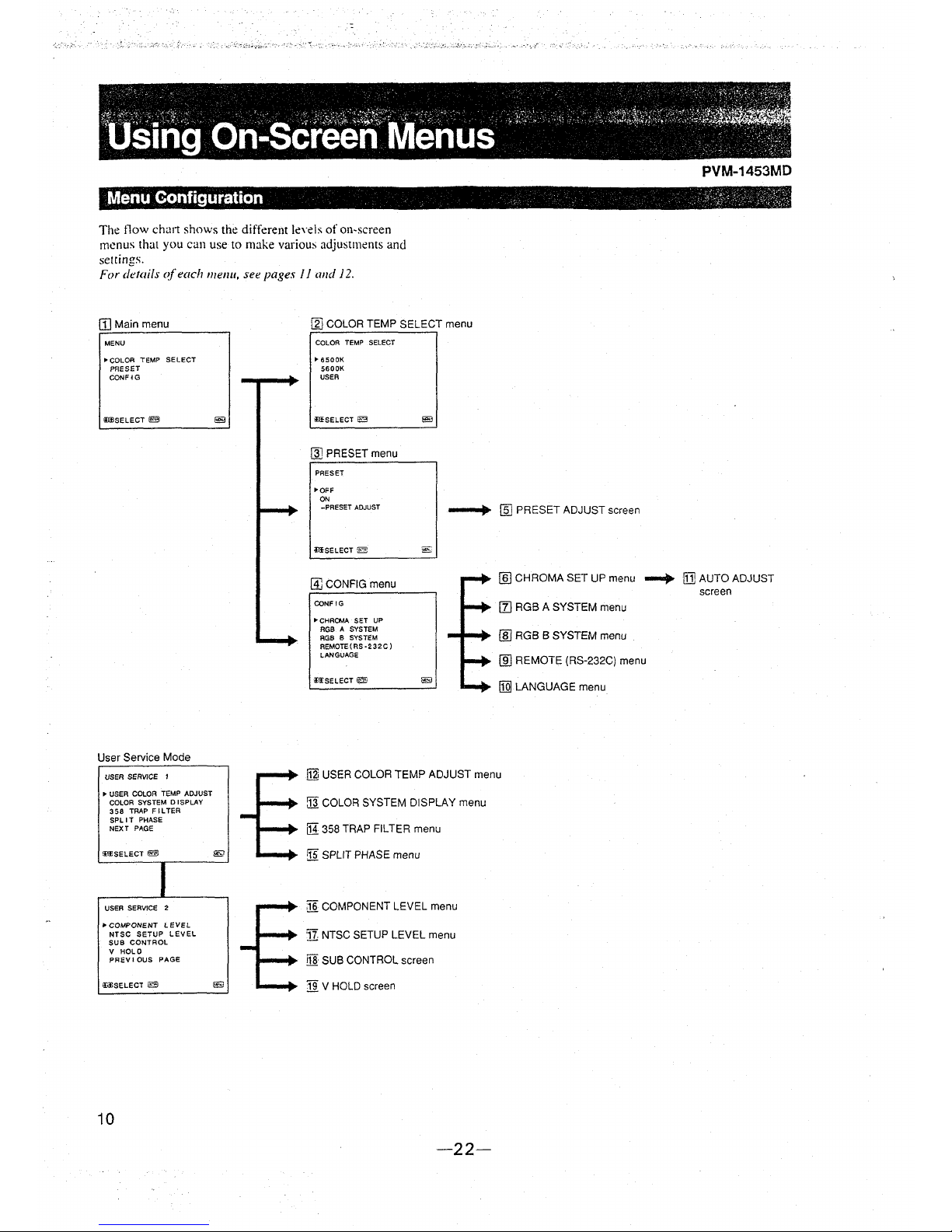
The flow cha11 shows the different Je,·els of on-screen
menus that you can use to make various
adjustments and
settings.
For details <!leach 111e1111, see pages J J and J 2.
[j] Main menu
~
COLOR TEMP SELECT menu
MENU
• COLOR TEMP SELECT
PRESET
CONFlG
(IJJ)SELECT
~
COLOR TEMP SELECT
"'6500K
5600K
USER
ilJ.fSELECT :§1
@] PRESET menu
PRESET
•OFF
ON
-PRESET ADJUST
msELECT 2
@] CONFIG menu
CONF IG
"'CHRCMA SET UP
RGB A SYSTEM
RGB B SYSTEM
REMOTE( RS
·232C)
~
[fil PRESET ADJUST screen
~
[§] CHROMA SET UP menu
[z] RGB A SYSTEM menu
(ID RGB B SYSTEM menu
....
LANGUAGE
(ID REMOTE (RS-232C) menu
User Service Mode
USER SERVICE
'
• USER COLOR TEMP ADJUST
COLOR SYSTEM DI SPLAY
358 TRAP FILTER
SPLIT PHASE
NEXT PAGE
!l1ESELECT
~
I
USER SERVICE 2
• COMPONENT LEVEL
NTSC SETUP LEVEL
SUB CONTROL
V HOLD
PREVIOUS PAGE
iL11SELECT iel
10
@
@
fi:SELECT
~
~
[Q] LANGUAGE menu
fil] USER COLOR TEMP ADJUST menu
:J1 COLOR SYSTEM DISPLAY menu
[H 358 TRAP FIL TEA menu
!Ji SPLIT PHASE menu
]1 COMPONENT LEVEL menu
Jl NTSC SETUP LEVEL menu
!li! SUB CONTROL screen
19 V HOLD screen
-22-
PVM-1453MD
ITIJ AUTO ADJUST
screen
i,;;,,,.:;1,;,,:,-,~~~~,t,::'.,!Wi!i>:S(>l--,iL, :., i ;, ' ' ' ,;f:ft ' ' ' ,,,
... , ........._
. . "" -
. -
' ~' ' • ~ '_t ' < •
~
' '
:operating-through~Nlenus. >- , :-_ '.'
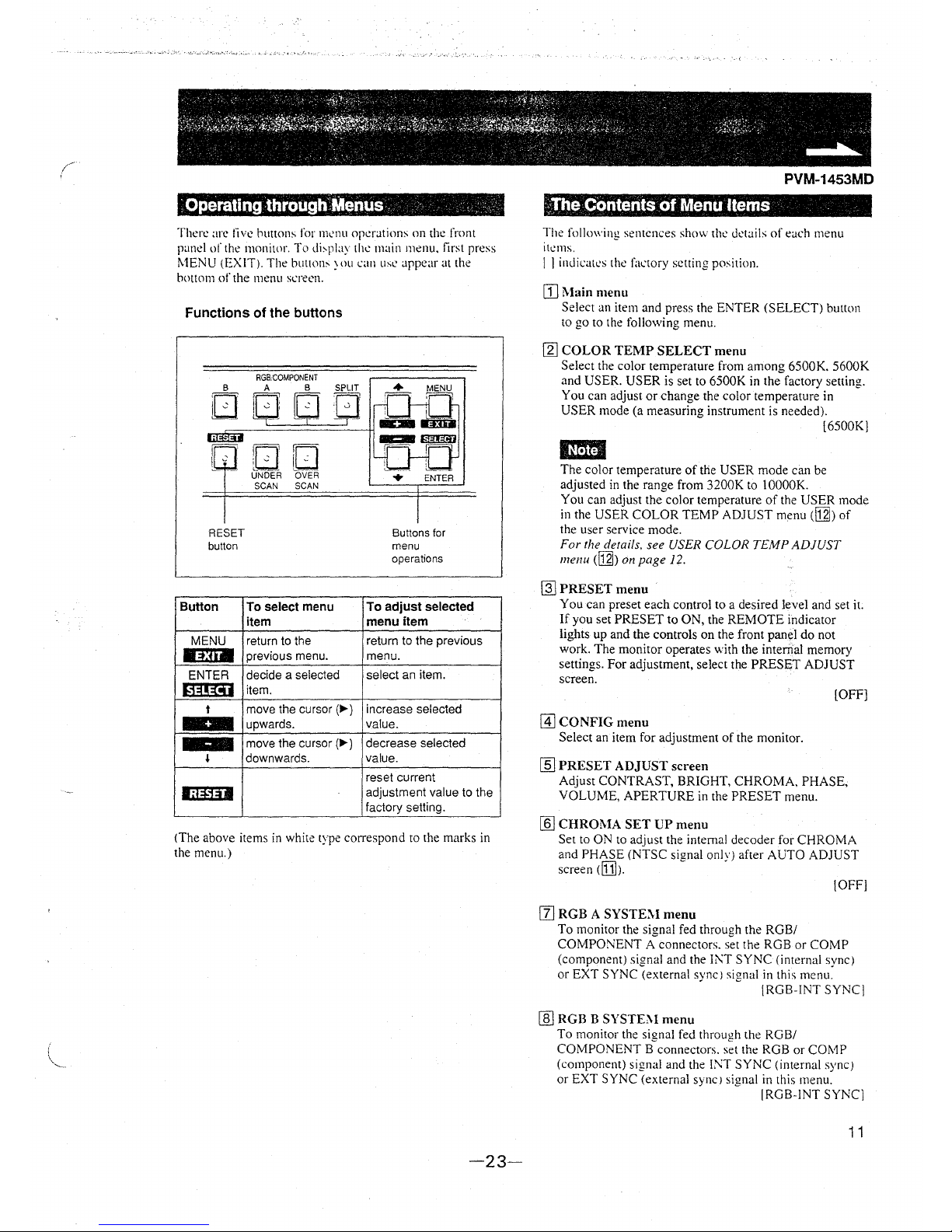
There arc five huttons for menu operations on the front
panel of the monitor_ To di~play the main menu. first press
MENU (EXIT). The hutton, ::,m1 can use appear at the
hottom
of the menu screen.
Functions of the buttons
B
iO
=--
RESET
button
Button
MENU
.!3i11
ENTER
(1~!~!ii
t
'
lili131
RGRCOMPONENT
A B SPLIT
[JD
=o·
I , , , . , ,_
j V i '- V
~- ·r- -1
~
DO
UNDER OVER
SCAN SCAN
To select menu
item
return to the
previous menu.
decide a selected
item.
move the cursor (,._)
upwards.
move the cursor(,..)
downwards.
+ ENTER
Buttons for
menu
operations
To adjust selected
menu item
return to the previous
menu.
select an item.
increase selected
value.
decrease selected
value.
reset current
adjustment value to the
factory setting.
(The above items in white type correspond to the marks in
the menu.)
-23-
PVM-1453MD
},l'he Contents of Menu Items
The following sentences show the details of each menu
items.
I I indicates the factory setting position.
[TI Main menu
Select an item and press the ENTER (SELECT) button
to go to the following menu.
[gJ COLOR TEMP SELECT menu
Select the color temperature from among 6500K. 5600K
and USER. USER is set to 6500K in the factory setting.
You can adjust or change the color temperature in
USER mode (a measuring instrument is needed).
[6500K]
IUfttl
The color temperature of the USER mode can be
adjusted in the range from
3200K to 10000K.
You can adjust the color temperature of the USER mode
in the USER COLOR TEMP ADJUST menu
([gj) of
the user service mode.
For the details, see USER COLOR TEMP ADJUST
menu
([gj) on page 12.
~
PRESET menu
You can preset each control to a desired level and set it.
If you set PRESET to ON, the REMOTE indicator
lights up and the controls on the front panel do not
work. The monitor operates with the
internal memory
settings. For adjustment, select the PRESET ADJUST
screen.
[OFF]
@J CONFIG menu
Select an item for adjustment of the monitor.
[ID PRESET ADJUST screen
Adjust CONTRAST, BRIGHT, CHROMA, PHASE,
VOLUME, APERTURE in the PRESET menu.
lli] CHROMA SET UP menu
Set to ON to adjust the internal decoder for CHROMA
and PHASE (NTSC signal only) after AUTO ADJUST
screen
dU]J.
!OFF]
[zJ RGB A SYSTE'.\1 menu
To monitor the signal fed through the RGB/
COMPONENT A connectors, set the RGB or COMP
(component) signal and the 11\T SYNC (internal sync)
or EXT SYNC (external sync l signal in this menu.
IRGB-INT SYNC]
[ill RGB B SYSTE:\1 menu
To monitor the signal fed through the RGB/
COMPONENT B connectors. set the RGB or COMP
(component) signal and the
INT SYNC (internal sync)
or EXT SYNC (external sync) signal in this menu.
IRGB-INT SYNC]
11
..
~;, ..,.", ~: ... i·f·' . >:, ,,,_:~./ • ... ~.;-",.,,: '>' l
~
" ~ ' • ' > • • •
isillg 6n-Screen Menus .. · .••.. . ·. · •
(ID REMOTE (RS-232C) menu
Select one out of following three modes.
REMOTE OFF:
You
can adjust settings and controls by the buttons
and controls on
the front panel.
The RS-232C connector does not function.
REMOTE ONLY:
You
can adjust settings and controls through the
RS-2:12C connector.
Buttons and controls on the front panel, except the
menu operation ones, do not functin.
REMOTE & LOCAL:
You can adjust settings and controls both through the
RS-232C connector and the front panel buttons.
Controls on the front panel do not function.
[REMOTE OFF]
[ill LANGUAGE menu
You can select the language used for on-screen menus
from the following five languages (English, German.
French, Italian, Spanish). [ENGLISH!
\TI] AUTO ADJUST screen
Select the color bar signal (full, SMPTE, EIA) and press
the ENTER (SELECT) button to start automatic
adjustment for CHROMA and PHASE. For these
adjustments to be valid, you must select ON in
CHROMA SET UP menu
([ill).
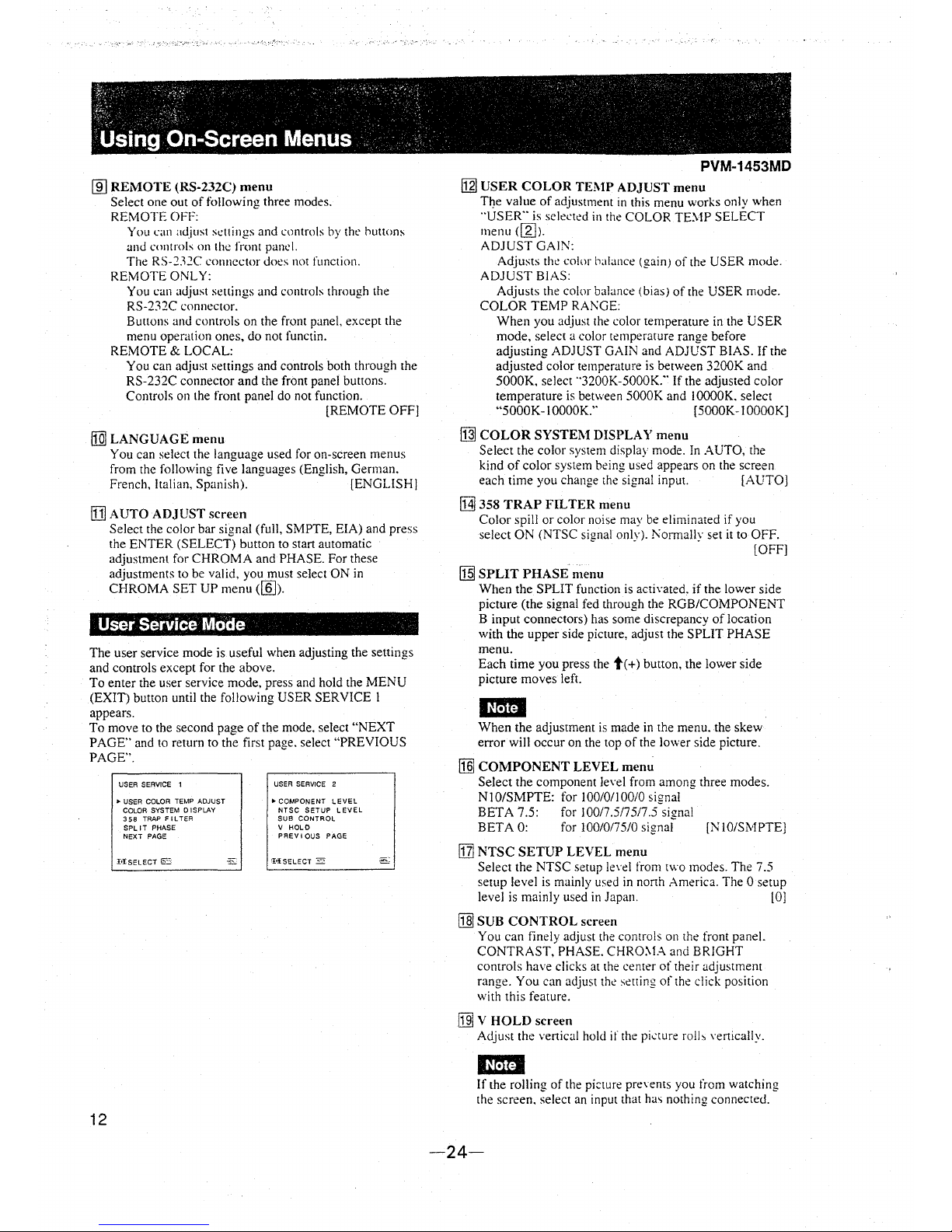
User Service Mocle
The user service mode is useful when adjusting the settings
and controls except
for the above.
To enter the user service mode, press and hold the MENU
(EXIT) button
until the following USER SERVICE I
appears.
To
move to the second page of the mode. select "NEXT
PAGE" and to return to the first page. select "PREVIOUS
PAGE".
12
USER SERVICE 1
., USER COLOR TEMP ADJUST
COLOR SYSTEM O 1SPLAY
358 TRAP FILTER
SPLIT PHASE
NEXT PAGE
USER SERVICE 2
• COMPONENT LEVEL
NTSC SETUP LEVEL
SUB CONTROL
V HOLD
PAEV I OUS PAGE
'I
1
1SELECT 2
El
I
PVM-1453MD
[gj USER COLOR TEl\tP ADJUST menu
T~e value of adjustment in this menu works only when
"'USER" is selected in the COLOR TE'.vlP SELECT
menu
([g]).
ADJUST GAIN:
Adjusts
the color balance (gain) of the USER mode.
ADJUST BIAS:
Adjusts the color balance (bias) of the USER mode.
COLOR TEMP
RANGE:
When you adjust the color temperature in the USER
mode, select a color temperature range before
adjusting ADJUST GAIN and ADJUST BIAS. If the
adjusted color temperature is between 3200K and
5000K, select
.. 3200K-5000K:· If the adjusted color
temperature is between 5000K and l OOOOK. select
"5000K-IOOOOK.'' [5000K-IOOOOK]
~
COLOR SYSTEM DISPLAY menu
Select the color system display mode. In AUTO, the
kind of color system being used appears on the screen
each time you change the signal input. [AUTO]
M 358 TRAP FILTER menu
Color spill or color noise may be eliminated if you
select ON (NTSC signal only).
l'\ormally set it to OFF.
[OFF)
[§I SPLIT PHASE n1enu
When the SPLIT function is acti\'ated. if the lower side
picture (the signal fed through the RGB/COMPONENT
B input connectors) has some discrepancy of location
with the upper side picture, adjust the SPLIT PHASE
menu.
Each time you press the
t( +) button, the lower side
picture moves left.
l~Mti
When the adjustment is made in the menu. the skew
error will occur on the top of the lower side picture.
[§] COMPONENT LEVEL menu
Select the component Je\·el from among three modes.
NIO/SMPTE: for I00/0/100/0 signal
BETA 7.5: for I00/7.5/75/7.5 signal
BETA 0: for 100/0/75/0 signal
[N 10/Sivf PTEJ
[Z] NTSC SETUP LEVEL menu
Select the NTSC setup le\·el from two modes. The 7.5
setup level is mainly used in north America. The O setup
level is mainly used in Japan. l OJ
G]J SUB CONTROL screen
You can finely adjust the controls on the front panel.
CONTRAST, PHASE.
CHRO:-lA and BRIGHT
controls
have clicks at the center of their adjustment
range. You can adjust
the setting of the click position
with this feature.
[ill V HOLD screen
Adjust the vertical hold if the pi..:ture rolb Yertically.
l~Mti
If the rolling of the pi::ture preYents you from watching
the screen, select an input that
ha, nothing connected.
-24-
;,;::1('' . . ">,,,,, ·'~f·::'. .
Power so·~~ces · . '.·:.~:·~
. '
PVM-1453MD
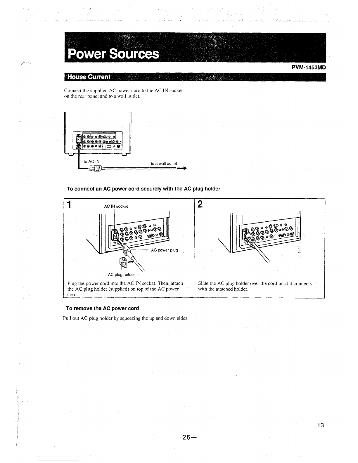
Connect the supplied AC power cord tn the AC IN socket
on the rear panel and to a wall outlet.
to a wall outlet
==========-+
To connect an AC power cord securely with the AC plug holder
1 AC IN socket
,-~
AC plug holder
Plug the power cord into the AC IN socket. Then, attach
the AC plug holder (supplied) on top of the AC power
cord.
To remove the AC power cord
Pull out AC plug holder by squeezing the up and down sides.
-25-
2
Slide the AC plug holder over the cord umil it connects
with the attached holder.
13
,t. '·>_ tt' .. · ' . . - · ... /\ :: ' ,-:··". ·:,:··::;:~;~::\\:;., ... >.~-~\.·:·_;;'.:\ .. :,-.· :····::·:-,·~~')(
·Attaching the Splash Proof-Coliers :· · · · ·.,_!
In order to protect the ventilation holes from splashes (of
medicines, etc.). attach the splash proof covers (supplied) as
shown below.
1
Nails on the upper edge
Splash proof covers
Making sure the arrows on the cover are facing down,
hook the nails on the upper edge into the ventilation holes.
Em
2
PVM-1453MD
'--'-I-- Nails on the
bottom edge
Push up the nails on the bottom edge and fit the co\·er into
the lowest ventilation holes.
Attach the both covers to the left and right sides.
Attach the splash proof covers to all them ventilation holes.
:,_"-¥~-' ', ,-:,~':,, ,,~,,..,,7' , -,~'· ' :
~ ~
,'~ '
Attachiqg the eOnttOllBSnel ,~over . · ......
In order to protect the control buttons on the front panel
from undesired touching, attach the supplied control panel
cover.
1
LL
~-------'---- Panel hinges
Attach the panel hinges to the left and right grips from the
inner side.
14
2
~r----
Control panel cover
Fit the bosses on the both sides of the control panel cover
into the lower holes of
the panel hinges with bending the
control panel cover a little.
-26-
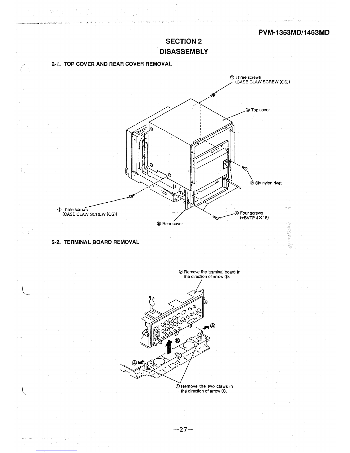
l
SECTION 2
DISASSEMBLY
PVM-1353MD/1453MD
2-1. TOP COVER AND REAR COVER REMOVAL
2-2. TERMINAL BOARD REMOVAL
CD Three screws
(CASE CLAW SCREW (OS))
® Remove the terminal board in
the direction of arrow
®·
CD Remove the two claws in
the direction of arrow
®·
-27-
@Top cover
® Six nylon rivet
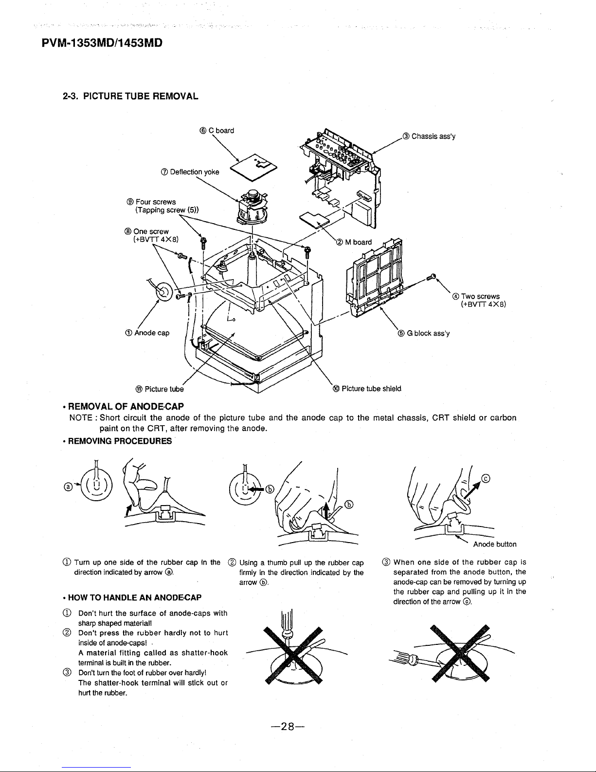
PVM-1353MD/1453MD
2-3. PICTURE TUBE REMOVAL
® Cboard
(l) Defleciioo yo~
@ Chassis ass'y
~""
@Two screws
~
(+BVTT 4X8)
@ G block ass'y
• REMOVAL OF ANODE,CAP
NOTE : Short circuit the anode of the picture tube and the anode cap to the metal chassis, CRT shield or carbon
paint on the CRT, after removing the anode.
• REMOVING PROCEDURES
CD Turn up one side of the rubber cap in the @ Using a thumb pull up the rubber cap
direction indicated by arrow
@. firmly in the direction indicated by the
arrow@.
• HOW TO HANDLE AN ANODE-CAP
CD Don't hurt the surface of anode-caps with
sharp shaped material!
@ Don't press the rubber hardly not to hurt
inside of anode-caps! .
A material fitting called as shatter-hook
terminal is built in the rubber.
® Don't turn the foot of rubber over hardly!
The shatter-hook terminal will stick out or
hurt the rubber.
-28-
® When one side of the rubber cap is
separated from the anode button, the
anode-cap can be removed by turning up
the rubber cap and pulling up it in the
direction of the arrow
©.
 Loading...