

Sony Trinitron KV-AR29T80C,Trinitron KV-AR29X80C Service Manual
HISTORY
When clicking an item, it’s detail is displayed.
Date SUPP./CORR. Description of SUP/COR
Change of
main text
2004.06 NEW –
Model Name: KV-AR29T80C/AR29X80C
SERVICE MANUAL
Part No. : 9-XXX-XXX-01
CHASSIS
SERVICE MANUAL
MODEL COMMANDER DEST. CHASSIS NO.
–––––– –––––––––––– ––––– –––––––––––
MODEL COMMANDER DEST. CHASSIS NO.
–––––– –––––––––––– ––––– –––––––––––
BY-1A
KV-AR29T80C RM-W104 China SCC-M35A-A
KV-AR29X80C RM-W104 China SCC-M35B-A
TRINITRON COLOR TV
R
RM-W104 KV-AR29T80C/AR29X80C
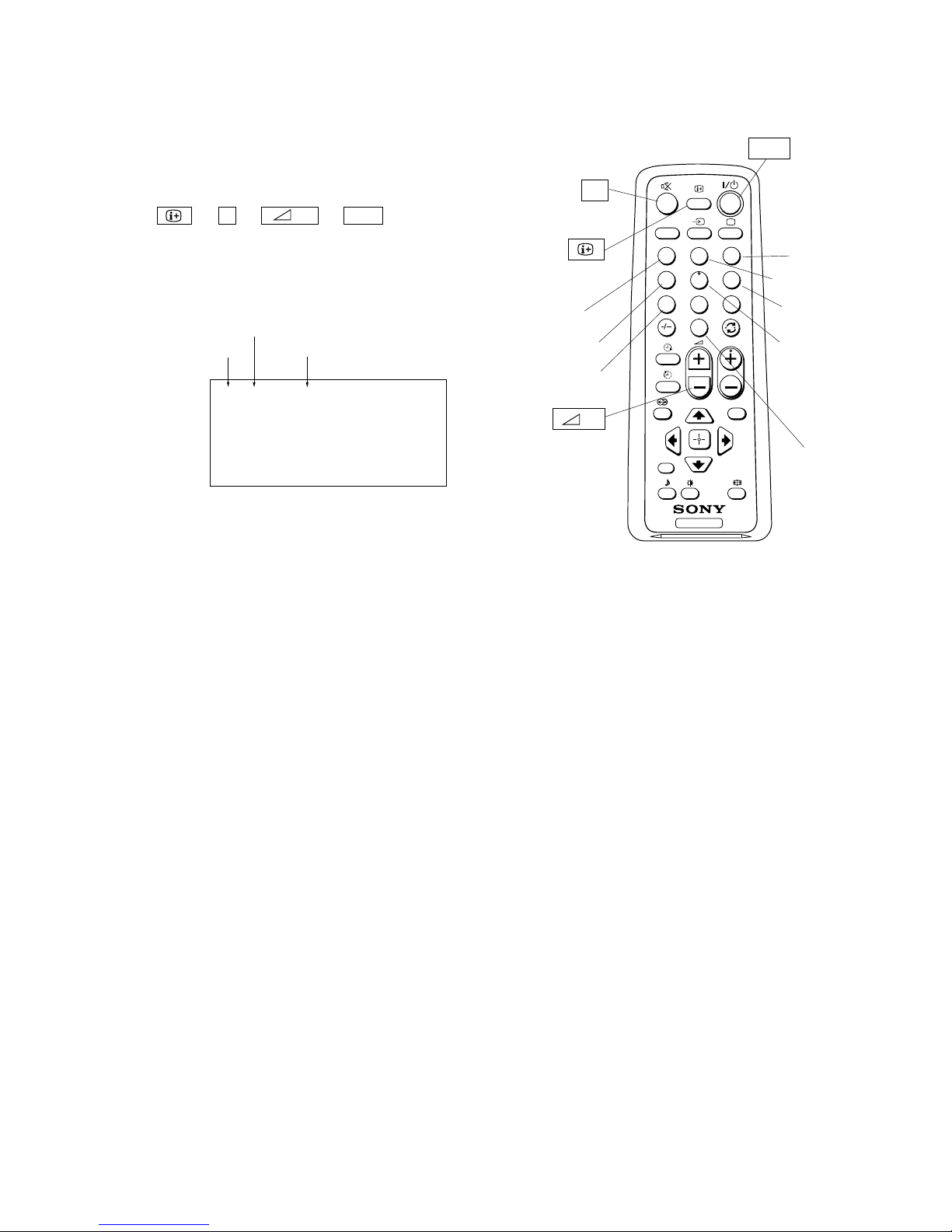
TV
1
2
3
4
6
7
8
9
0
5
MENU
PROG
A/B
RESET

– 2 –
KV-AR29T80C/AR29X80C
RM-W104 RM-W104
(CAUTION)
SHORT CIRCUIT THE ANODE OF THE PICTURE TUBE AND THE
ANODE CAP TO THE METAL CHASSIS, CRT SHIELD, OR CARBON PAINTED ON THE CRT, AFTER REMOVING THE ANODE.
WARNING!!
AN ISOLATION TRANSFORMER SHOULD BE USED DURING
ANY SERVICE TO AVOID POSSIBLE SHOCK HAZARD, BECAUSE OF LIVE CHASSIS.
THE CHASSIS OF THIS RECElVER IS DIRECTLY CONNECTED
TO THE AC POWER LINE.
SAFETY-RELATED COMPONENT WARNING!!
COMPONENTS IDENTIFIED BY SHADING AND MARK ! ON
THE SCHEMATIC DIAGRAMS, EXPLODED VIEWS AND IN THE
PARTS LIST ARE CRITICAL TO SAFE OPERATION. REPLACE
THESECOMPONENTS WITH SONY PARTS WHOSE PART NUMBERS APPEAR AS SHOWN IN THIS MANUAL OR IN SUPPLEMENTS PUBLISHED BY SONY. CIRCUIT ADJUSTMENTS THAT
ARE CRITICAL TO SAFEOPERATION ARE IDENTIFIED IN THIS
MANUAL. FOLLOW THESE PROCEDURES WHENEVER CRITICAL COMPONENTS ARE REPLACED OR IMPROPER OPERATION IS SUSPECTED.

– 3 –
KV-AR29T80C/AR29X80C
RM-W104 RM-W104
Section Title Page
–––––– –––– ––––
Section Title Page
–––––– –––– ––––
6. DIAGRAMS
6-1. BLOCK DIAGRAM (1) ........................................... 21
BLOCK DIAGRAM (2) ........................................... 23
BLOCK DIAGRAM (3) ........................................... 25
BLOCK DIAGRAM (4) ........................................... 27
6-2. CIRCUIT BOARDS LOCATION ................................. 29
6-3. SCHEMATIC DIAGRAMS .......................................... 29
Schematic Diagram of A (1/3) Board ........................ 31
Schematic Diagram of A (2/3) Board ....................... 33
Schematic Diagram of A (3/3) Board ....................... 35
Schematic Diagram of C Board ................................ 37
Schematic Diagram of D3, H Board ........................ 39
Schematic Diagram of J Board ................................ 41
Schematic Diagram of U Board ............................... 43
6-4. PRINTED WIRING BOARD ........................................ 45
• A Board ................................................................... 45
• C Board ................................................................... 47
• D3 Board ................................................................. 48
• H Board ................................................................... 49
• J Boards .................................................................. 50
• U Board ................................................................... 51
6-5. WAVEFORMS ............................................................... 53
6-6. SEMICONDUCTORS ................................................... 54
7. EXPLODED VIEWS
7-1. CHASSIS SECTION ................................................ 55
7-2. CRT SECTION ......................................................... 56
7-3. BEZEL SECTION ..................................................... 57
8. ELECTRICAL PARTS LIST.
• A Board ............................................................................... 58
• C Board ............................................................................... 63
• D3 Board ............................................................................. 64
• H Board ............................................................................... 64
• J Board ................................................................................ 64
• U Board ............................................................................... 64
TABLE OF CONTENTS
1. SPECIFICATIONS ............................................................. 4
2. DISASSEMBLY
2-1. REAR COVER............................................................ 5
2-2. SERVICE POSITION ................................................. 5
2-3. SPEAKER ................................................................... 6
2-4. D3 BOARD ................................................................. 6
2-5. H, J BOARDS ............................................................. 6
2-6. TERMINAL BRACKET ............................................. 7
2-7. A BOARD ................................................................... 7
2-8. U BOARD ................................................................... 8
2-9. C BOARD ................................................................... 8
2-10. HARNESS ARRANGEMENT ................................... 8
2-11. REMOVAL OF ANODE-CAP .................................... 9
2-12. CRT ........................................................................... 10
3. SERVICE MODE
3-1. METHOD OF SETTING THE SERVICE
ADJUSTMENT MODE ............................................ 11
3-2. SERVICE MODE ADJUSTMENT........................... 11
3-3. MEMORY WRITE CONFIRMATION METHOD .. 11
3-4. ADJUSTING BUTTONS AND INDICATOR ......... 11
3-5. SERVICE MODE LIST ............................................ 12
4. SET-UP ADJUSTMENTS
4-1. BEAM LANDING .................................................... 14
4-2. CONVERGENCE ADJUSTMENT .......................... 15
4-3. G2 (SCREEN) ADJUSTMENT ................................ 17
4-4. FOCUS ADJUSTMENT 1 ........................................ 17
4-5. NECK ASSY TWIST ADJUSTMENT ..................... 17
4-6. SFC COARSE ADJUSTMENT ................................ 17
4-7. SUB COLOR ADJUSTMENT ................................. 18
4-8. SUB HUE ADJUSTMENT....................................... 18
4-9. FOCUS ADJUSTMENT 2 ........................................ 18
5. SAFETY RELATED ADJUSTMENTS
5-1. CHECKING OCP OPERATION .............................. 19
5-2. CONFIRMATION OF V-PROTECTOR .................. 19
5-3. CHECKING POWER SUPPLY VOLTAGES .......... 19

– 4 –
KV-AR29T80C/AR29X80C
RM-W104 RM-W104
KV-AR29T80C
Note
KV-AR29X80C
Power requirements 220 V AC, 50 Hz
Power consumption (W) Indicated on the rear of the TV
Television system B/G, I, D/K, M
Color system PAL, NTSC3.58, NTSC4.43
Channel coverage
B/G VHF : E2 to E12
UHF : E21 to E69
CATV : S01 to S03, S1 to S41
I UHF : B21 to B68
CATV : S01 to S03, S1 to S41
D/K VHF : C1 to C12, R1 to R12
UHF : C13 to C57, R21 to R60
CATV : S01 to S03, S1 to S41, Z1 to Z39
M VHF : A2 to A13
UHF : A14 to A79
CATV : A-8 to A-2, A to W+4, W+6 to W+84
8(Antenna) 75-ohm external terminal
Audio output (Speaker) 7 W + 7 W (6 W + 6 W for 7% distortion)
Number of terminal
(Video) Input: 3 Output: 1 Phono jacks; 1 Vp-p, 75 ohms
(Audio) Input: 3 Output: 1 Phono jacks; 500 mVrms
(S Video) Input: 1 Y: 1 Vp-p, 75 ohms, unbalanced,
sync negative
C: 0.286 Vp-p, 75 ohms
(Component Input: 1 Phono jacks; Y: 1 Vp-p, 75 ohms,
Video) sync negative
C
B
: 0.7 Vp-p, 75 ohms
CR: 0.7 Vp-p, 75 ohms
Audio: 500 mVrms
Picture tube 29 type
Tube size (cm) 72 Measured diagonally
Screen size (cm) 68 Measured diagonally
Dimensions (w/h/d, mm) 765 x 578 x 502
Mass (kg) 48
Design and specifications are subject to change without notice.
SECTION 1
SPECIFICATIONS
– 5 –
KV-AR29T80C/AR29X80C
RM-W104 RM-W104
SECTION 2
DISASSEMBLY
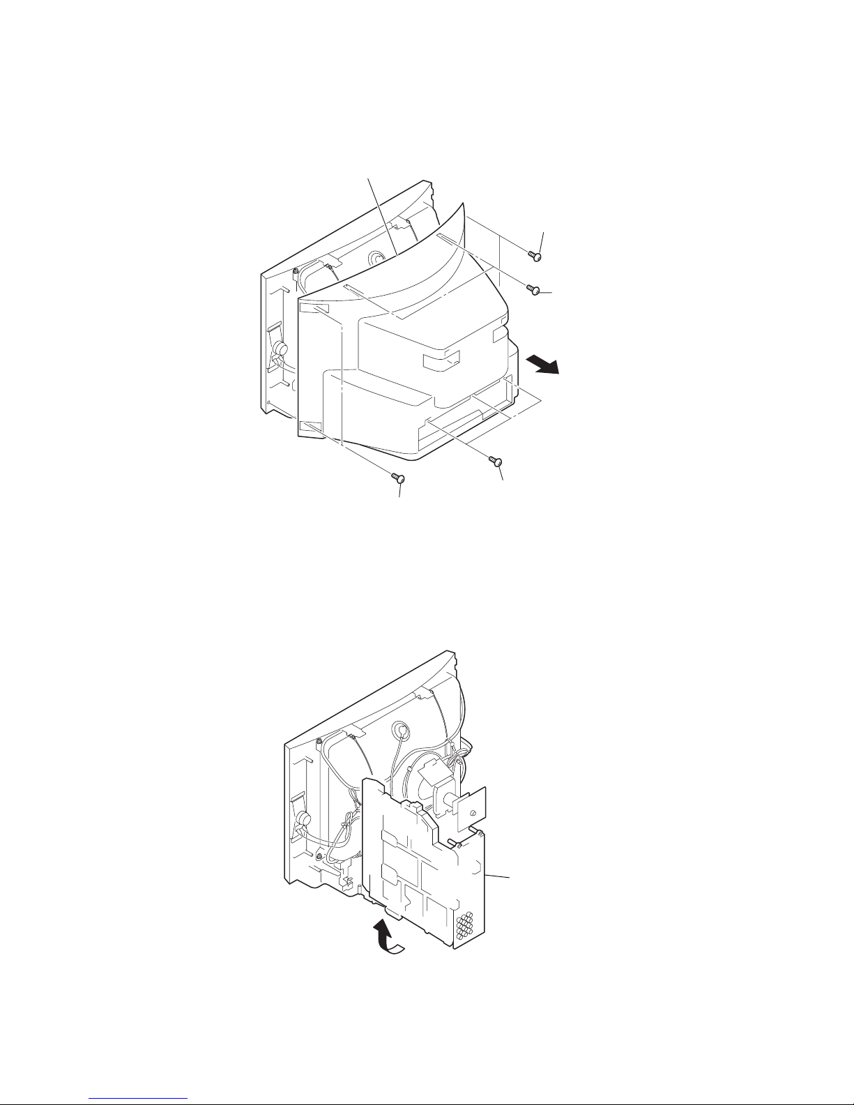
2-1. REAR COVER
2-2. SERVICE POSITION
1 Two screws
(+BVTP 4x16)
1 Two screws
(+BVTP 4x16)
3 Rear cover
2
1 Three screws
(+BVTP 4x16)
1 Two screws
(+BVTP 4x16)
Main bracket assembly
1
– 6 –
KV-AR29T80C/AR29X80C
RM-W104 RM-W104
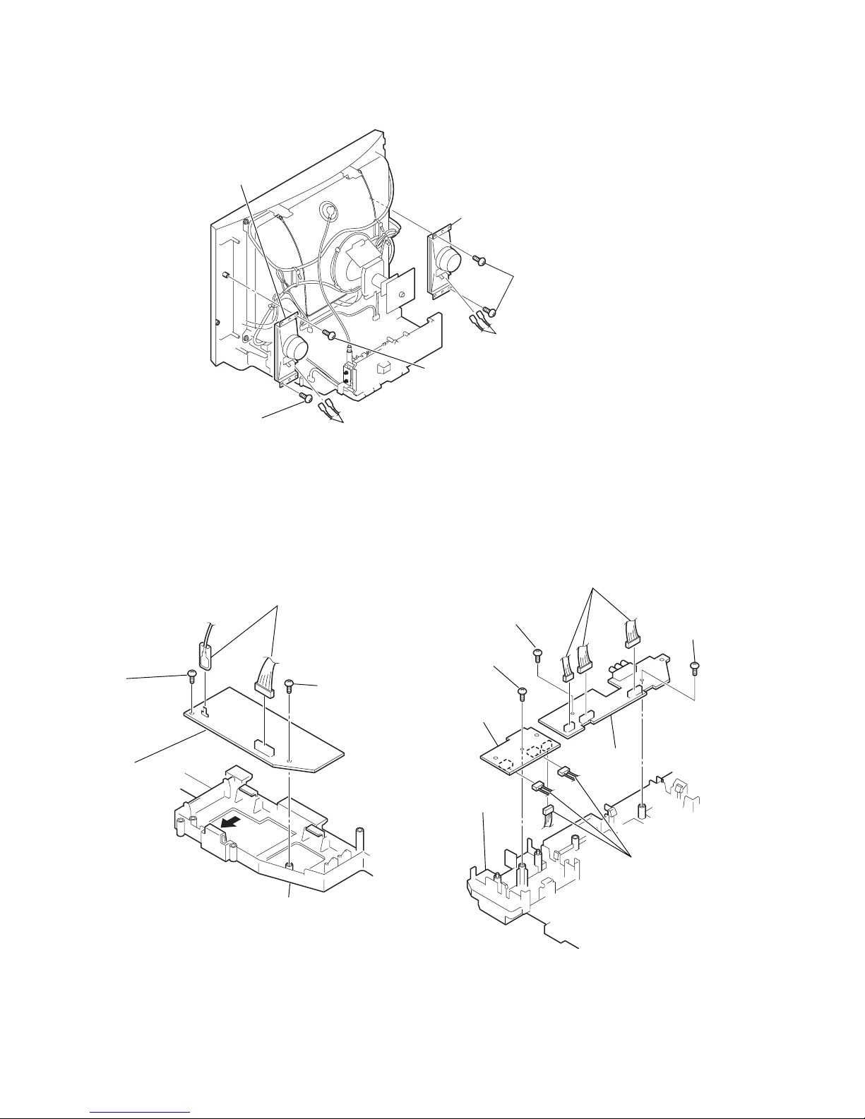
2-5. H, J BOARDS
2-3. SPEAKERS
2-4. D3 BOARD
2 Screw
(+BVTP 4x12)
3 Speaker
6 Speaker
2 Screw
(+BVTP 4x12)
5 Two screws
(+BVTP 4x12)
4 Cables
1 Cables
2 Screw
(+BVTP 3x12)
2 Screw
(+BVTP 3x12)
1 Two connectors
3 D3 board
Main bracket
2 Screw
(+BVTP 3x12)
5 Screw
(+BVTP 3x12)
2 Screw
(+BVTP 3x12)
1 Three connectors
4 Three connectors
6 J board
3 H board
Main bracket
– 7 –
KV-AR29T80C/AR29X80C
RM-W104 RM-W104
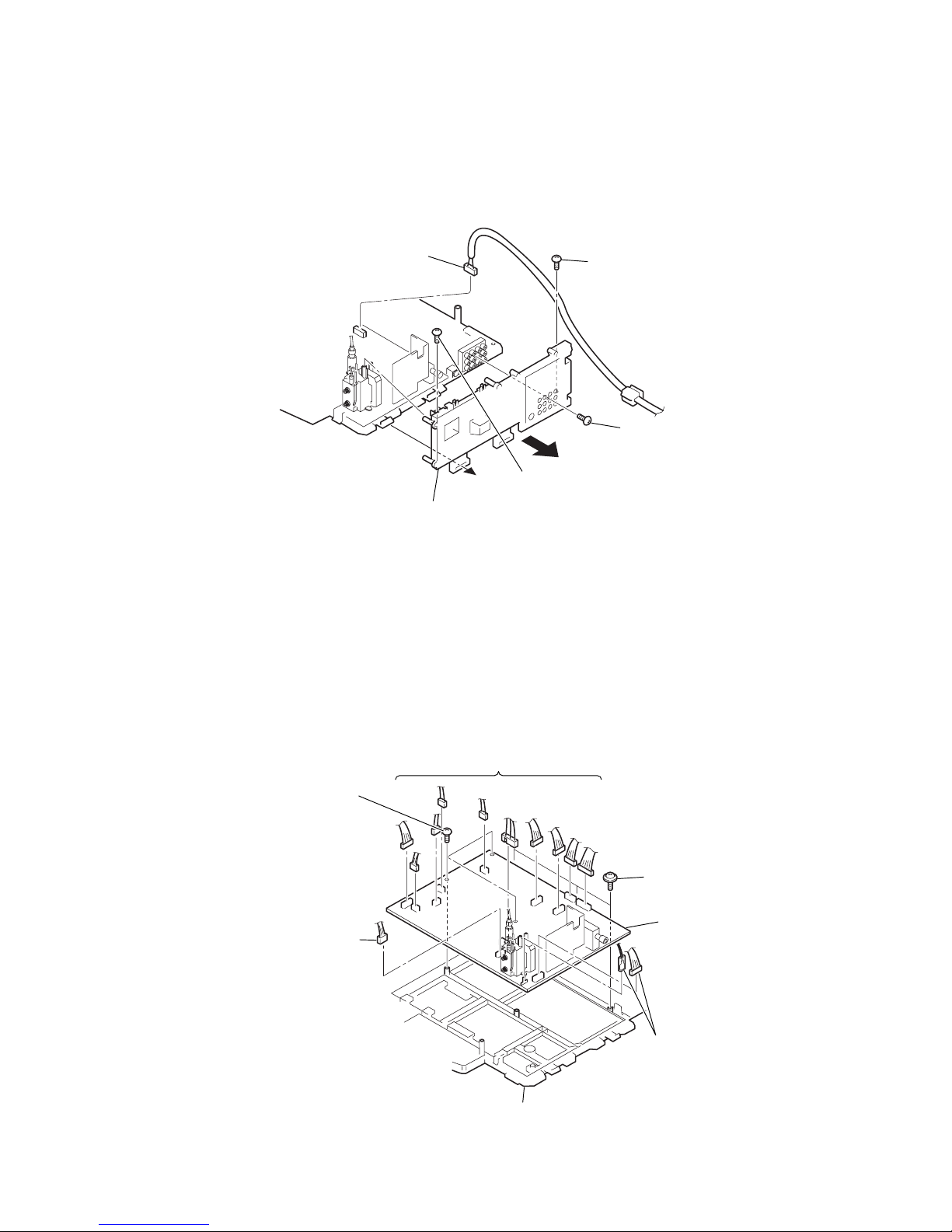
2-6. TERMINAL BRACKET
2-7. A BOARD
2 Screw
(+BVTP 3x12)
2 Screw
(+BVTP 3x12)
1 Connector
4 Ter minal bracket
3
2 Screw
(+BVTP 3x12)
2 Three screws
(+BVTP 3x12)
2 Three screws
(+PWH 3x12)
1 Connectors
1 Connector
1 Connector
3 A board
Main bracket
– 8 –
KV-AR29T80C/AR29X80C
RM-W104 RM-W104
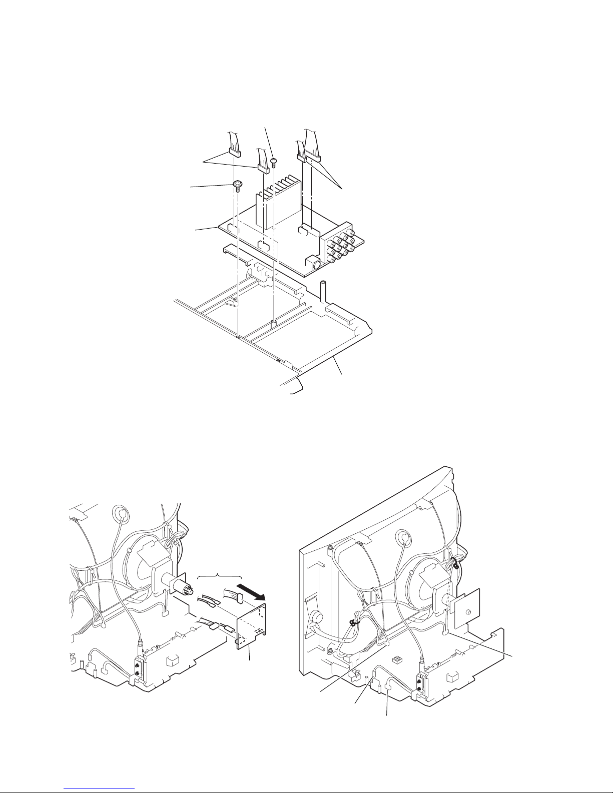
2-8. U BOARD
2-9. C BOARD
2 Screw
(+BVTP 3x12)
2 Screw
(+BVTP 3x12)
1 Two connectors
3 U board
Main bracket
1 Two connectors
3 C board
1 Connectors
2
2-10. HARNESS ARRANGEMENT
CN2800
CN401
CN2803
CN603
– 9 –
KV-AR29T80C/AR29X80C
RM-W104 RM-W104
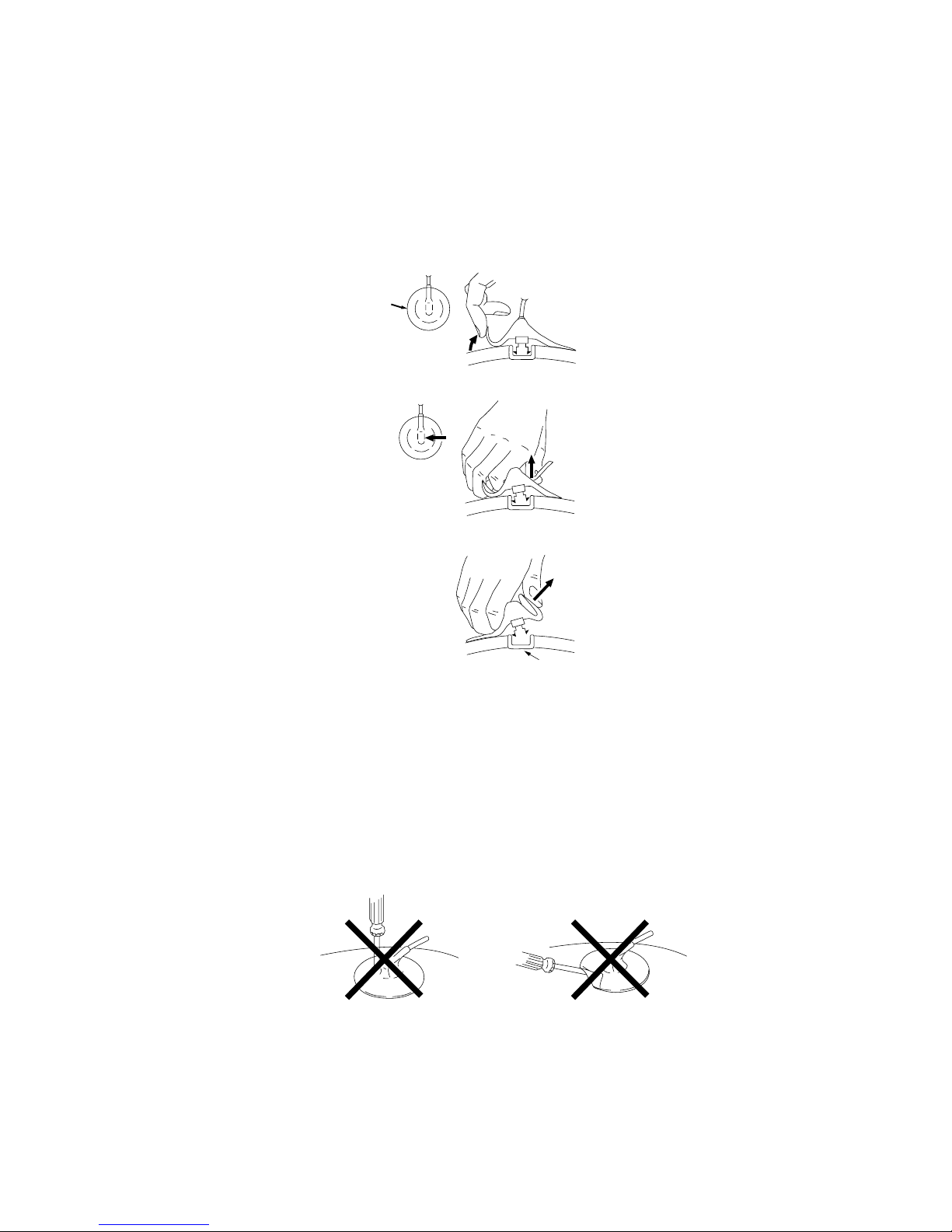
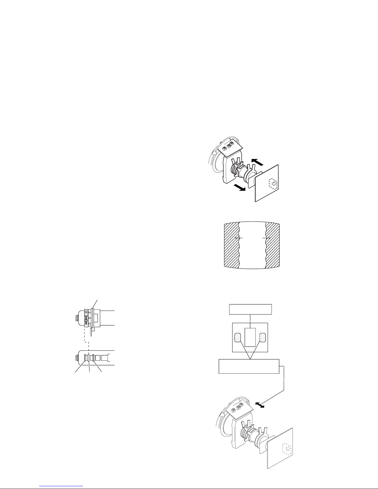
2-11. REMOVAL OF ANODE-CAP
NOTE : After removing the anode, short circuit the anode of the picture tube and
the anode cap to the metal chassis, CRT shield or carbon paint on the
CRT.
• REMOVING
PROCEDURES
1 Do not dama
ge the surface
of anode-caps with
sharp shaped objects.
2 Do not press
the rubber too hard
so as not to damage the inside of
anode-cap.
A metal fitting called
the shatter-hook terminal is built into
the rubber.
3 Do not turn
the foot of rubber over too hard.
The shatter-hook
terminal will stick out
or damage the rubber
.
• HOW TO HANDLE AN ANODE-CAP
3 When one side of the rubber cap is separated
from the anode b
utton, the anode-cap
can be removed by turning up the rubber cap and pulling it up in the direction of the
arrow
c.
2 Using a thumb pull up the rubber
cap firmly in the direction
indicated by the arrow b
.
1 Turn up one side of the rubber cap in the
direction indicated
by the arrow a.
a
a
b
b
c
– 10 –
KV-AR29T80C/AR29X80C
RM-W104 RM-W104
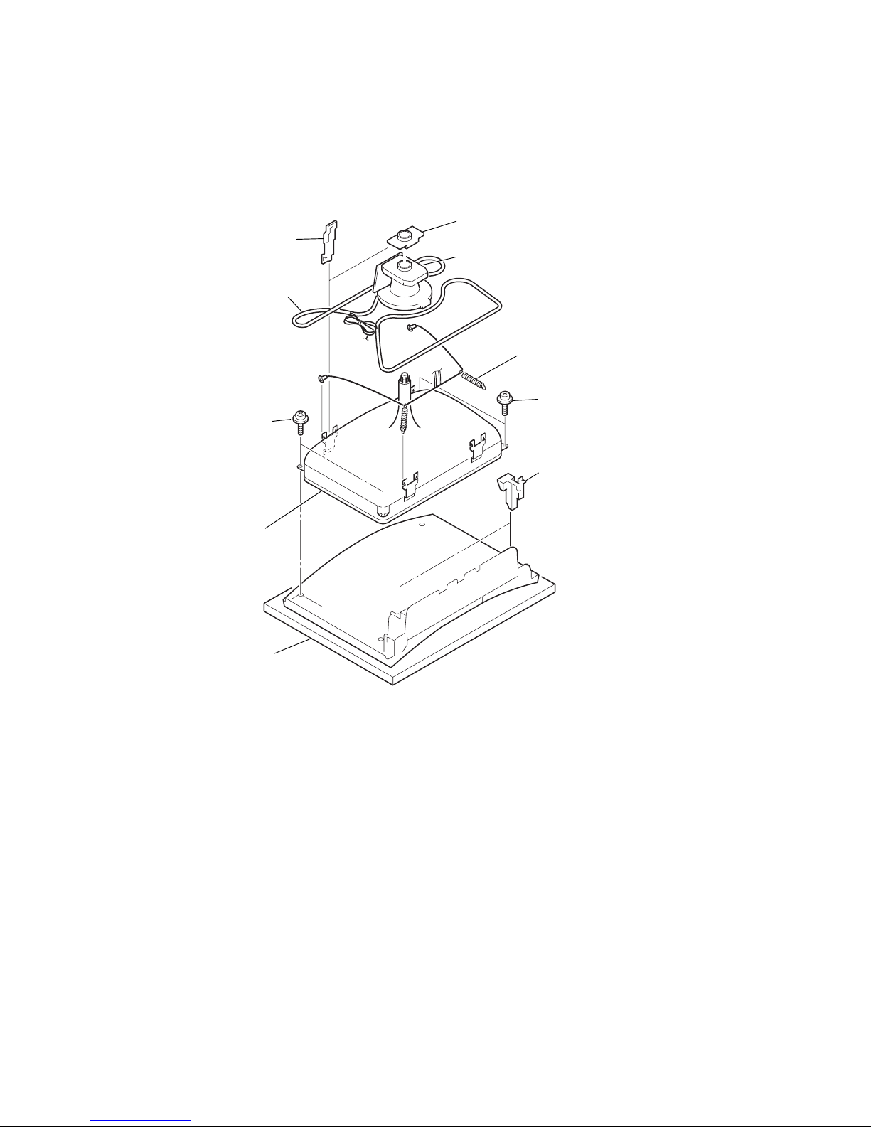
2-12. CRT
NOTE: After removing the anode, short circuit the anode of the picture tube
and the anode cap to the metal chassis, CRT shield or carbon paint
on the CRT.
6 Two screws
tapping 7 +crown washer
6 Two screws
tapping 7 +crown washer
7 Two CRT supporters
Bezel assembly
3 Springs with ground wires
8 CRT
1 DGC clip
5 Deflection Yoke
4 Neck assembly
2 Degauss coil
– 11 –
KV-AR29T80C/AR29X80C
RM-W104 RM-W104
TV
1
2
3
4
6
7
8
9
0
5
MENU
PROG
A/B
RESET
3. The SCREEN displays the item being adjusted.
4. Press 1 or 4 on the Remote Commander to select the
adjustment item.
5. Press 3 or 6 on the Remote Commander to change the data.
6. Press 2 or 5 on the Remote Commander to select the
category.
7. If you want to recover the latest values press 7 then - to read
the memory.
8. Press [ MUTING ] then - to write into memory.
9. Turn power off.
Note: Press 8 then - on the Remote Commander to initialize
or turn set off and on to exit.
3-3. MEMORY WRITE CONFIRMATION METHOD
1. After adjustment, turn power off with the remote commander.
2. Turn power on and set to Service Mode.
3. Call the adjusted items again and confirm they were adjusted.
3-1. METHOD OF SETTING THE SERVICE ADJUSTMENT
MODE
SERVICE MODE PROCEDURE
1. Standby mode. (Power off)
2. n 5 n (+) n =/1
on the Remote Commander.
(Press each button within a second.)
3-2. SERVICE MODE ADJUSTMENT
3-4. ADJUSTING BUTTONS AND INDICATOR
RM-W104
Adjustment item up
Category up
Data up
Data down
Category down
Data
OSD 0 OSV 32 SERVICE 50 CH 1
Item NO.(register name)
Category
Adjustment item down
SECTION 3
SERVICE MODE
(+)
%
=/1
-
Read
– 12 –
KV-AR29T80C/AR29X80C
RM-W104 RM-W104
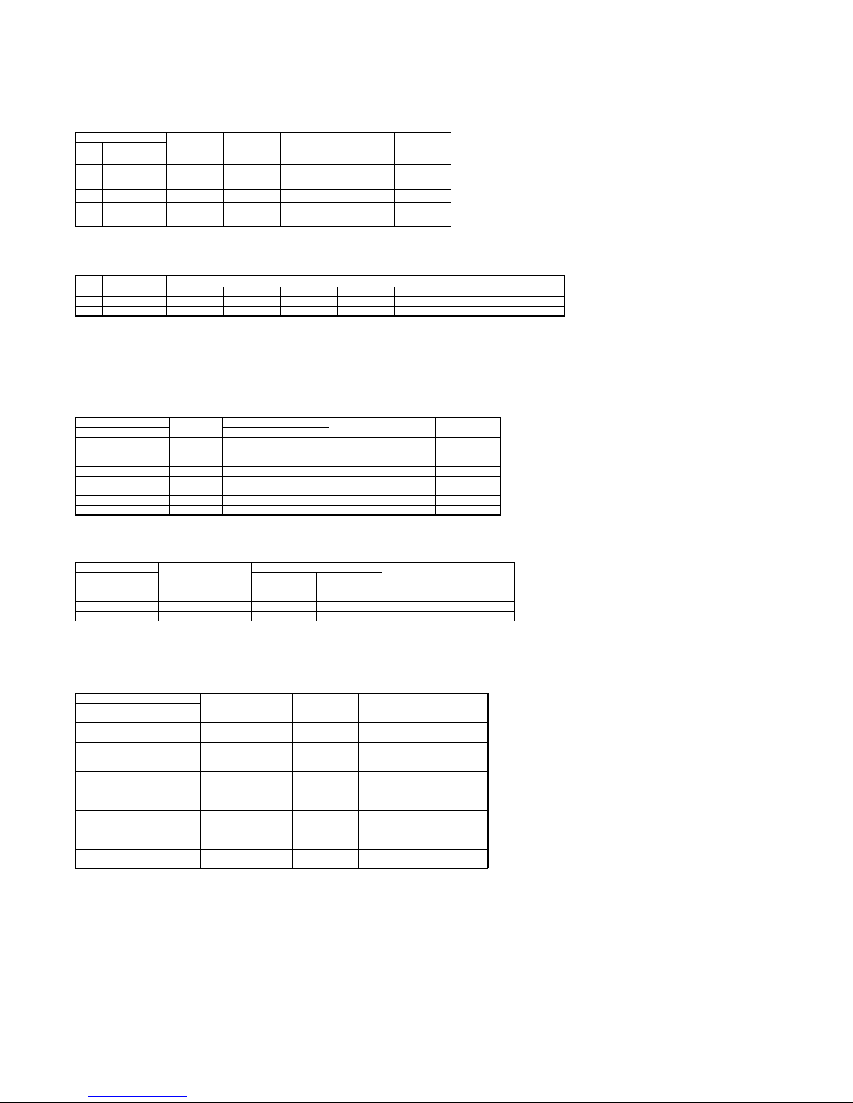
AP
No. Name
0SUBVS-OFF
0 - 3
02
1SUBVS-SIMU
0 - 3
02
2SUBVS-ON
0 - 3
00
3BASS
0 - 15
*1
4TREBLE
0 - 7
*1
5SURROUND 1 - 2 *1
Standards *1
PERSONAL TV-DYNAMIC TV-DRAMA TV-SOFT AV-DYNAMICE AV-DRAMA AV-SOFT
3BASS 7 12 10912109
4TREBLE 3654654
Sub volume surround on
Bass control
Treble control
Surround co ntrol
Funct ion Remar ksStandards
No. ITEM
Funct ionalit y
Range
Standards
Sub volume surround off
Sub volume stereo
3-5.SERVICE LIST
DEF1
No. Name 50Hz 60Hz
0H-PARALLEL 0 - 63 15 15 Horizontal parallelogram
1H-BOW 0-63 1B 1 9 Horizo ntal bow
2H-SHIFT 0-63 25 2C Horizontal shift
3H-WIDTH 0-63 2
A
2A EW width
4H-PARABOLA 0 - 63 15 18 EW parabola
5H-U.CORNER 0 - 63 19 1
F
EW uppercorner parabola
6H-L..CORNER 0-63 16 1D E W lower cor ner parabola
7H-TRAPE 0-63 28 29 EW trapezium
Remarks
Functionality Standards
Range Function
DEF2
No. Nam
e
50Hz 60Hz
0V-SLOPE 0-63 2B 2B Ver tical slope
1V-AMPL.. 0-63 38 3CVertical amplitud
2V-S.CORR 0-63 1C 24 Ver tical s correction
3V-SHIFT 0-63 20 20 Vertical shift
Remarks
Funct ionalit
y
Range
Standards
Function
OP0
No. Name
0FMWS0/1
1IFAGC SPEED
NORM / 0.7◊NORM /
3◊NORM / 6◊ NORM
83
2BlueSCREEN1/0 83
3FOAB
NORM/SLOW/SLOW
FAST/FAST
83
4FORFS
LAST FIELD
FREQUENCY/ATUO
50HZ IF NO SYNC/AUTO
60HZ IF NOSYNC/60HZ
83
5RP010
1:1.8/1:1/1: 1.25/1:1.5
BE
6EVG
OK/NO
BE
7DSK
DYNAMIC SKIN
OFF/DYNAMIC SKIN ON
0F
8HCO
EHT ONVERTICAL/EHT
ON VERT. AND HORI.
0F
Remarks
Funct ionalit y
Range Standar ds F unction

– 13 –
KV-AR29T80C/AR29X80C
RM-W104 RM-W104
OP1
No. Name
0SOUND SYSTEM I DK / M I DK / BG I DK / M BG I DK 0F
1VIDEOMUTE YES/NO 0F
2SVM YES / NO 0F
3COMBFILTER YES/NO 0F
4 UOC VOLUME 0 - 63 33
Remarks
Funct ionalit y
Range St andards Funct ion
OP2
No. Name
0 NVM WRIGHT 0/1
1 AUTO-SHUTOFF OK/NO BE
2WOOFER OK/NO BE
3AVL ON/OFF BE
4 OVERSCAN TIME: 000MS - 310MS 00
Remarks
Functiona lity
Range Standar ds Functio n
VP
No. Name
0Y-DELAY 0-15 *1
1AGC-TAK 0-63 1F
2CATHODE 0 - 15 05
3SUB-COL -15 - +15 *2
4SUB-BRT -15-+15 *2
5SUB-HUE -15 - +15 *2
6SUB-SHP -15 - +15 *2
Standards *1
PAL NTSC 4.43NTSC3.58
0Y-DELAY 03 03 03 03
Standards *2
TV PAL TV NTSC AV PAL AV NTSC DVD PAL DVD NTSC
3SUB-COL 0A 09 09 07 08 0D
4SUB-BRT 0E 0E 11 11 10 10
5SUB-HUE 0F 0E 0F 0E 0F 0F
6SUB-SHP 05 05 17 17 17 17
Funct ionalit y
Range FunctionStandard s Remarks
Ydelay
AGC v oltag e adjustment
Catho de voltageadjustment
Sub color adjustment
Sub brightnessadjustment
Sub HUE adjustment
Sub sharpness adjustment
No. ITEM
Standards
No. ITEM
Standards
NON FRONT-END
WB
No. Name TV/AV DYAMIC DVD DYNAMIC T V/AV OTHER DVD OTHER
0RCT 0-63 1D 1 E 1E 1E Black level offset R
1GCT 0-63 1
A
1C 1C 15 Black level o ffset G
2RDR 0-63 21 2C 2C 26 Red
g
ain
3 GDR 0 - 63 21 28 28 23 Gr een gain
4BDR 0-64 28 25 25 1
F
Blue gain
5RGBOFF ON/OFF RGB on/off
Remarks
StandardsFunct ionalit y
Range Function
– 14 –
KV-AR29T80C/AR29X80C
RM-W104 RM-W104
SECTION 4
SET-UP ADJUSTMENTS
• The following adjustments should be made when a complete
realignment is required or a new picture tube is installed.
• These adjustments should be performed with rated power
supply voltage unless otherwise noted.
Controls and switches should be set as follows unless otherwise
noted:
PICTURE control ........................................................... normal
BRIGHTNESS control................................................... normal
Perform the adjustments in the following order :
1. Beam Landing
2. Convergence
3. Focus
Note : Test Equipment Required.
1. Color-bar/Pattern Generator
2. Degausser
3. Oscilloscope
...................................................................................................................................................................
Preparation :
• In order to reduce the influence of geomagnetism on the set’s
picture tube, face it east or west.
• Switch on the set’s power and degauss with the degausser.
4-1. BEAM LANDING
1. Input a white signal with the pattern generator.
Contrast
Brightness
2. Position neck assy as shown in Fig4-1.
3. Set the pattern generator raster signal to a green raster.
4. Move the deflection yoke to the rear and adjust with the purity control so that the green is at the center and the blue and
the red take up equally sized areas on each side.
(See Figures 4-1 through 4-3.)
5. Move the deflection yoke forward and adjust so that the
entire screen is green. (See Figure 4-2.)
6. Switch the raster signal to blue, then to green and verify the
condition.
7. When the position of the deflection yoke has been decided,
fasten the deflection yoke with the screws and DY spacers.
normal
}
Neck assy
G2G1 G3
Behind the G2 edge
Fig. 4-1
Fig. 4-3
Red
Blue
Green
Fig. 4-4
Purity control
corrects this area.
Deflection yoke positioning
corrects these areas.
Fig. 4-2
– 15 –
KV-AR29T80C/AR29X80C
RM-W104 RM-W104
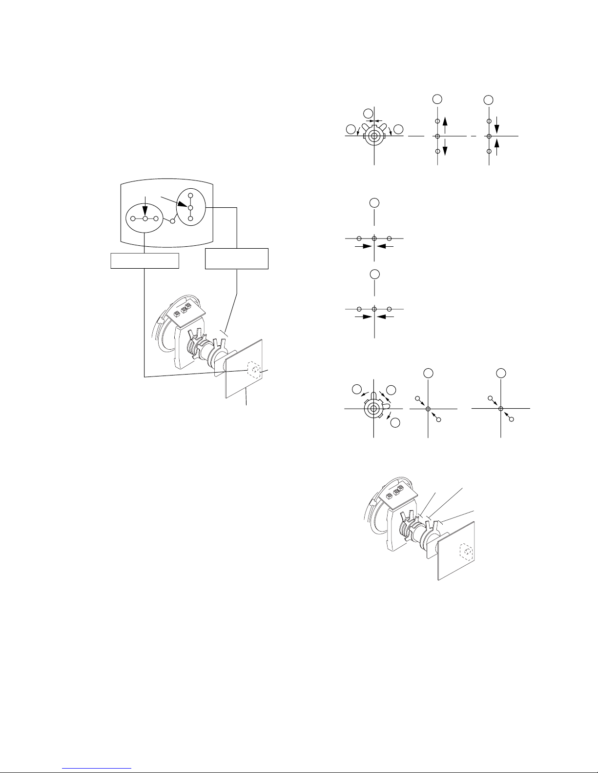
4-2. CONVERGENCE ADJUSTMENT
Preparation :
• Before starting this adjustment, adjust the focus, horizontal
size and vertical size.
• Set the Picture Mode to “STANDARD”.
• Cross hatch / Dot pattern.
4-2-1. Horizontal and Vertical Static Convergence
1. (Moving horizontally), adjust the H.STAT control so that the
red, green and blue dots are on top of each other at the center
of the screen.
2. (Moving vertically), adjust the V.STAT magnet so that the
red, green and blue dots are on top of each other at the center
of the screen.
3. If the H.STAT variable resistor cannot bring the red, green
and blue dots together at the center of the screen, adjust the
horizontal convergence with the H.STAT variable resistor and
the V.STAT magnet in the manner given below.
(In this case, the H.STAT variable resistor and the V.STAT
magnet influence each other, so be sure to perform adjustments while tracking.)
Center dot
R G B
R
G
B
H. STAT VR
V. S TAT
Magnet
RV702
H. STAT
C Board
1
V. STAT
2
H. STAT VR
R
R
G
G
B
B
a
a
b
b b
R
RGGBB
a
b
3
R
R
GG
B
B
a
a
b
b
b
V. STAT
Purity
BMC
 Loading...