

Sony TRINITRON BVM-20M4DE, TRINITRON BVM-20M4E, TRINITRON BVM-14M4DE, TRINITRON BVM-14M4E Operation Manual [it, en]
Page 1

TRINITRON® COLOR VIDEO MONITOR
BVM-20M4DE
BVM-20M4E
BVM-14M4DE
BVM-14M4E
OPERATION MANUAL
1st Edition (Revised 1)
English/Italian
Page 2

Owner’ s Recor d
The model and serial numbers are located at the rear.
Record these numbers in the spaces provided below.
Refer to these numbers whenever you call upon your
Sony dealer regarding this product.
Model No.
Serial No.
W ARNING
To prevent fire or shock hazard, do not
expose the unit to rain or moisture.
Dangerously high voltage are present
inside the unit.
Do not open the cabinet. Refer servicing
to qualified personnel only.
In the event of a malfunction or when maintenance is
necessary, consult an authorized Sony dealer.
V ORSICHT
WARNING
THIS APPARATUS MUST BE EARTHED
IMPORTANT
The wires in this mains lead are coloured in
accordance with the following code:
Green-and-yellow: Earth
Blue: Neutral
Brown: Live
As the colours of the wires in the mains lead of this
apparatus may not correspond with the coloured
markings identifying the terminals in your plug proceed
as follows:
The wire which is coloured green-and-yellow must be
connected to the terminal in the plug which is marked
by the letter E or by the safety earth symbol Y or
coloured green or green-and-yellow.
The wire which is coloured blue must be connected to
the terminal which is marked with the letter N or
coloured black.
The wire which is coloured brown must be connected
to the terminal which is marked with the letter L or
coloured red.
Ensure that your equipment is connected correctly - If
you are in any doubt consult a qualified electrician.
Um Feuergefahr und die Gefahr eines
elektrischen Schlages zu vermeiden, darf
das Gerät weder Regen noch Feuchtigkeit
ausgesetzt werden.
Im lnneren des Geräts liegt gefährliche
Hochspannung an. Öffnen Sie niemals das
Gehäuse, und überlassen Sie
Wartungsarbeiten stets nur qualifiziertem
Fachpersonal.
Sollten am Gerät Probleme auftreten oder
Wartungsarbeiten erforderlich werden, wenden Sie
sich an einen autorisierten Sony-Händler.
Page 3
For the customers in Europe
This product with the CE marking complies with both
the EMC Directive (89/336/EEC) and the Low Voltage
Directive (73/23/EEC) issued by the Commission of
the European Community.
Compliance with these directives implies conformity to
the following European standards:
• EN60950: Product Safety
• EN55103-1: Electromagnetic Interference (Emission)
• EN55103-2: Electromagnetic Susceptibility
(Immunity)
This product is intended for use in the following
Electromagnetic Environment(s):
E1 (residential), E2 (commercial and light industrial),
E3 (urban outdoors) and E4 (controlled EMC
environment, ex. TV studio).
Pour les clients européens
Ce produit portant la marque CE est conforme à la fois
à la Directive sur la compatibilité électromagnétique
(EMC) (89/336/CEE) et à la Directive sur les basses
tensions (73/23/CEE) émises par la Commission de la
Communauté européenne.
La conformité à ces directives implique la conformité
aux normes européennes suivantes:
• EN60950: Sécurité des produits
• EN55103-1: Interférences électromagnétiques
(émission)
• EN55103-2: Sensibilité électromagnétique (immunité)
Ce produit est prévu pour être utilisé dans les
environnements électromagnétiques suivants:
E1 (résidentiel), E2 (commercial et industrie légère),
E3 (urbain extérieur) et E4 (environnement EMC
contrôlé ex. studio de télévision).
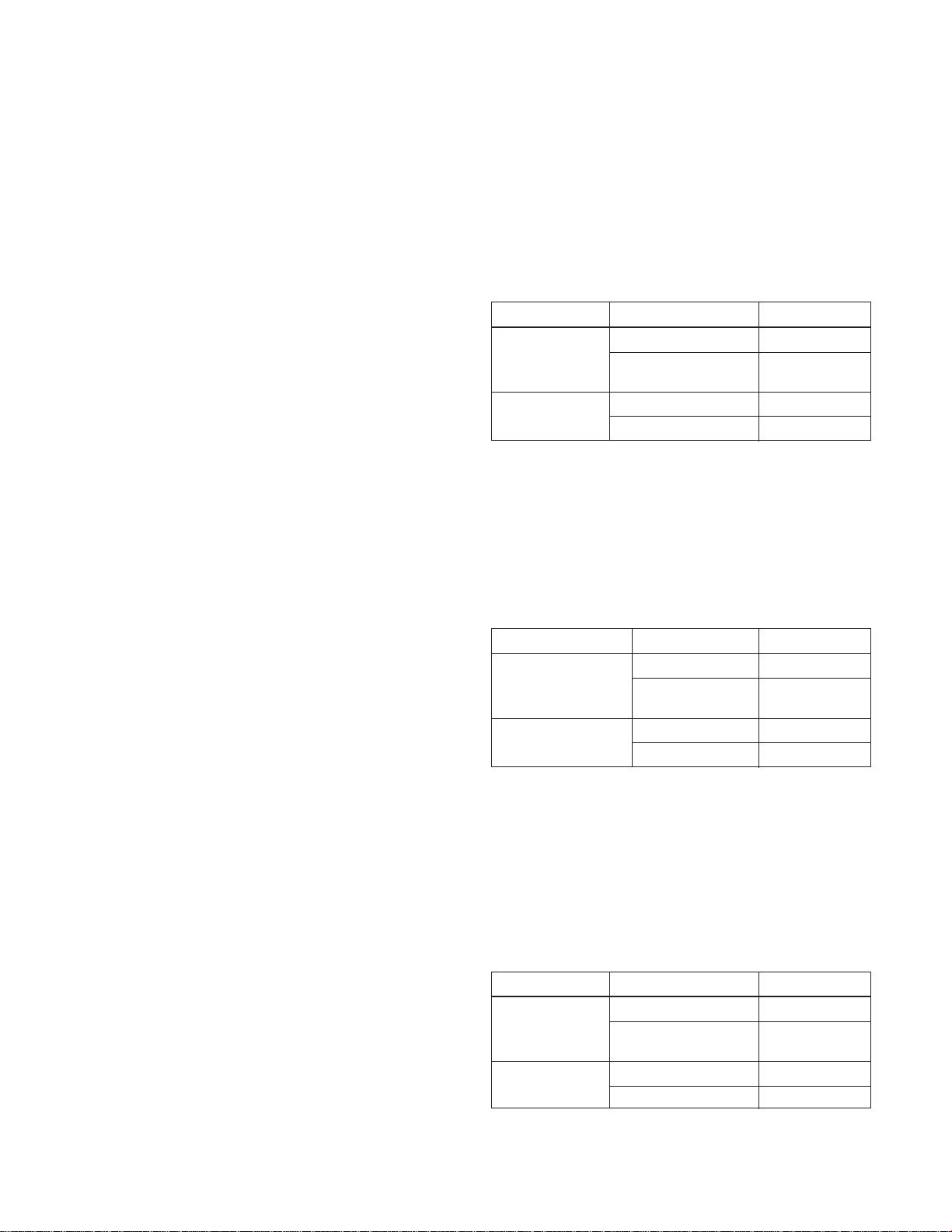
These products are designed for operation in the
environments E1 to E4. During EMC stress, the
performance (evaluated according to ITU/R 562-3 and
ITU/R 500-4) may degrade as shown in Table 1.
Without the EMC stress, all performance will recover to
full function.
Table 1
Frequency Level
14-inch Monitors 24-40 MHz 4-3
190-290, 360 and 4
420 MHz
20-inch Monitors 35-50 MHz 1
100 and 420 MHz 4
Ces produits sont conçus pour fonctionner dans les
environnements E1 à E4. Lors de contraintes EMC,
les performances (évaluées en fonction de ITU/R 5623 et ITU/R 500-4) risquent de chuter comme le montre
le tableau 1. Sans contrainte EMC, toutes les
performances reviennent à leur niveau maximum.
Tableau 1
Fréquence Niveau
Moniteurs 14 pouces 24-40 MHz 4-3
190-290, 360 et 4
420 MHz
Moniteurs 20 pouces 35-50 MHz 1
100 et 420 MHz 4
Für Kunden in Europa
Dieses Produkt besitzt die CE-Kennzeichnung und
erfüllt sowohl die EMV-Direktive (89/336/EEC) als
auch die Direktive Niederspannung (73/23/EEC) der
EG-Kommission.
Die Erfüllung dieser Direktiven bedeutet Konformität
für die folgenden Europäischen Normen:
• EN60950: Produktsicherheit
• EN55103-1: Elektromagnetische Interferenz
(Emission)
• EN55103-2: Elektromagnetische Empfindlichkeit
(Immunität)
Dieses Produkt ist für den Einsatz unter folgenden
elektromagnetischen Bedingungen ausgelegt:
E1 (Wohnbereich), E2 (kommerzieller und in
beschränktem Maße industrieller Bereich), E3
(Stadtbereich im Freien) und E4 (kontrollierter EMVBereich, z.B. Fernsehstudio)
Diese Produkte sind für den Einsatz in Umgebungen
vorgesehen, die den Normen E1 bis E4 entsprechen.
Bei EMV-Belastung kann die Leistung (bewertet nach
ITU/R 562-3 und ITU/R 500-4) wie in Tabelle 1
dargestellt abfallen. Bei Wegfall der EMV-Belastung
steigt die Leistung wieder auf den vollen Wert an.
Tabelle 1
Frequenz Stufe
14-Zoll-Monitore 24-40 MHz 4-3
190-290, 360 und 4
420 MHz
20-Zoll-Monitore 35-50 MHz 1
100 und 420 MHz 4
Page 4

Page 5
English
Precaution
Table of Contents
English
On safety
• Operate the unit only with a power source as
specified in “Specifications” section.
• The nameplate indicating operating voltage, power
consumption, etc., is located at the rear.
• Should any solid object or liquid fall into the cabinet,
unplug the unit and have it checked by qualified
personnel before operating it any further.
• Do not drop or place heavy objects on the power
cord. If the power cord is damaged, turn off the
power immediately. It is dangerous to use the unit
with a damaged power cord.
• Unplug the unit from the wall outlet if it is not to be
used for several days or more.
• Disconnect the power cord from the AC outlet by
grasping the plug, not by pulling the cord.
• The socket-outlet shall be installed near the
equipment and shall be easily accessible.
On installation
• Allow adequate air circulation to prevent internal
heat build-up.
Do not place the unit on surfaces (rugs, blankets,
etc.) or near materials (curtains, draperies) that may
block the ventilation holes.
• Do not install the unit in a location near heat sources
such as radiators or air ducts, or in a place subject to
direct sunlight, excessive dust, mechanical vibration
or shock.
Features ............................................................... 2(E)
Location and Function of Parts and Controls . 4(E)
Front ............................................................4(E)
Rear Panel ...................................................6(E)
Using On-Screen Menus..................................... 8(E)
On-Screen Menu Configuration ..................8(E)
Operation through On-Screen Menus .........9(E)
Functions of On-Screen Menus.................10(E)
Connections ....................................................... 12(E)
How to Connect the AC Power Cord ........12(E)
How to Connect a Cable to a
BNC Connector....................................12(E)
Specifications..................................................... 13(E)
About this manual
Before operating the unit, please read this manual
thoroughly and retain it for future reference.
The explanation given in this manual can be applied to
the following models unless noted otherwise.
When explanation differs among models, this is clearly
indicated in this manual.
• BVM-14M4DE/14M4E (14-inch monitor)
• BVM-20M4DE/20M4E (20-inch monitor)
Illustrations of the video monitor are of the BVM14M4DE.
On cleaning
To keep the unit looking brand-new, periodically clean
it with a mild detergent solution. Never use strong
solvents such as thinner or benzine, or abrasive
cleansers since they will damage the cabinet. As a
safety precaution, unplug the unit before cleaning it.
On repacking
Do not throw away the carton and packing materials.
They make an ideal container which to transport the
unit. When shipping the unit to another location,
repack it as illustrated on the carton.
If you have any questions about this unit, contact your
authorized Sony dealer.
1(E)
Page 6

Features
Picture
HR (High Resolution) Trinitron 1) picture tube
HR Trinitron tube provides a high resolution picture.
Horizontal resolution is more than 800 TV lines at the
center of the picture.
Comb filter
When NTSC video signals are received, a comb filter
activates to make more accurate Y/C separation. This
contributes to less of a decrease in resolution, cross
color and cross luminance phenomena.
Beam current feedback circuit
The built-in beam current feedback circuit assures
stable white balance.
Four color system available
The monitor can display NTSC, PAL, SECAM and
NTSC
selected automatically.
Blue only mode
In the blue only mode, an apparent monochrome
display is obtained with all three cathodes driven with
a blue signal. This facilitates color saturation and
phase adjustments and observation of VCR noise.
2)
4.43
signals. The appropriate color system is
Input
COMPONENT SDI3) input/output connectors
for BVM-20M4DE/14M4DE
SMPTE 259M 4:2:2 serial digital signal from a digital
VCR can be input and output through these
connectors.
When you install a Sony Component SDI kit <Audio>
BKM-102 (not supplied), you can monitor the sound
from serial digital input signals with the picture.
Analog RGB/component input connectors
Analog RGB or component (Y, R-Y and B-Y) signals
from video equipment can be input through these
connectors.
Y/C input connectors
The video signal, split into the chrominance signal (C)
and the luminance signal (Y), can be input through this
connector, eliminating the interference between the
two signals, which tends to occur in a composite video
signal, ensuring video quality.
External sync input
When the EXT SYNC selector is in the on position,
the monitor can be operated on the sync signal
supplied from an external sync generator.
4)
Automatic termination
(connector with
mark only)
The input connector is terminated at 75 ohms inside
when no cable is connected to the loop-through output
connector. When a cable is connected to an output
connector, the 75-ohm termination is automatically
released.
.........................................................................................................................................................................................................
1) “Trinitron” is a registered trademark of Sony
Corporation.
2) The NTSC4.43 system refers to an NTSC color system in
which the subcarrier frequency is modified to 4.43MHz.
When an NTSC recorded video program is played back
with a Trident (PAL/SECAM/NTSC4.43) VTR, the
NTSC4.43 signal is output.
3) SDI: Serial Digital Interface
4) The Sony Component SDI Kit BKM-101C (for video) is
built in BVM-20M4DE/14M4DE.
2(E)
Page 7
Functions
Underscan mode
The signal normally scanned outside of the screen can
be monitored in the underscan mode.
Note
When the monitor is in the underscan mode, the dark
RGB scanning lines may appear on the top edge of the
screen. These are caused by an internal test signal,
rather than the input signal.
Horizontal/vertical delay mode
The horizontal and vertical sync signals can be
checked simultaneously in the H/V delay mode.
Auto/manual degaussing
Degaussing of the screen can be performed
automatically when the power is turned on, or
manually by pressing the DEGAUSS button.
Five menu languages
You can select the menu language from among five
languages on the menu.
EIA 19-inch rack mount kit available
Use a suitable kit when rack mounting.
Europe MB-502C (14-inches) / SLR-103C (20-
inches
Any other area MB-502B (14-inches) /SLR-103A (20-
inches)
For details on mounting, refer to the instruction manuals
supplied with the mounting bracket kit or slide rail kit.
SDI (Serial Digital Interface) Kit (for audio) for
BVM-20M4DE/14M4DE
By using the Sony BKM-102 Component SDI Kit (for
audio, optional), you can monitor SMPTE 259M 4:2:2
serial digital audio signal from a digital VCR with the
picture.
On-screen menus
You can set color temperature, CHROMA SET UP,
and other settings by using the on-screen menus.
SDI (Serial Digital Interface) Kit for BVM20M4E/14M4E
By using the following optional SDI Kits, the monitor
can display SMPTE 259M 4:2:2 serial digital signal
from a digital VCR. (ex. Sony 4:2:2 VCR)
- BKM-101C: Component SDI Kit (for video)
- BKM-102: Component SDI Kit (for audio)
Note
When the serial number of the BKM-101C you want to
connect is less than 2,010,000, an optional connecting
harness (part no. 1-900-230-35) will be required.
Serial Remote Interface Kit
By using the Sony BKM-103 Serial Remote Interface
Kit (optional), the monitor can be controlled from
personal computers via the RS-422A serial interface.
3(E)
Page 8

Location and Function of Parts and Controls
Front
1
!ª
LINE/
RGB
H/V
DELAY
!¢!∞!§
!•
EXT
SYNC
16:9
!£
MENU
EXIT
SELECT
ENTER
!¡!™
APERTURE
MIN
@º@¡@™
A/
RGB
COMPONENT
DEGAUSS UNDER
RESET
BLUE
ONLY
SDI
SCAN
C/
B/
!¶
1 Tally lamp
Lights up when the video camera connected to this
monitor is selected, indicating that the picture is being
recorded.
For details on how to light the tally lamp, see page 14(E).
2 POWER switch and indicator
Depress to turn on the monitor. The indicator will light
green.
CONTRAST
MAX
–+
MIN
PHASECHROMABRIGHT
MAX
PUR GRN MIN MAX MIN MAX
VOLUME
POWER
REMOTE
5 CONTRAST control
Turn this control clockwise to make the contrast higher
or counterclockwise to make it lower.
6 PHASE control
This control is effective only for the NTSC and
NTSC
4.43 color systems. Turn it clockwise to make the
skin tones greenish or counterclockwise to make them
purplish.
234 567890
3 REMOTE indicator
Lights up when you select ON on the USER PRESET
menu (see page 11(E)), or when you connect a
supplied cable to the REMOTE connector. The
controls on the front panel do not work when this
indicator lights up.
For details on how to connect the cable, see page 14(E).
4 VOLUME control
Turn this control clockwise or counterclockwise to
obtain the desired volume.
4(E)
7 CHROMA control
Turn this control clockwise to increase the color
intensity or counterclockwise to decrease it.
8 BRIGHT (brightness) control
Turn this control clockwise to increase the brightness
or counterclockwise to decrease it.
9 APERTURE control
Turn this control clockwise to increase sharpness or
counterclockwise to decrease sharpness.
Page 9

Note
The PHASE (6), CHROMA (7) and APERTURE
(9) controls have no effect on the pictures of RGB
signals.
0 MENU/EXIT button
Press this button to display the main menu.
When a menu is on the display, you can return to the
previous menu by pressing this button.
!¡ ENTER/SELECT button
Press the button to confirm a selected item on the
menu.
!™ >/+ and ./– buttons
Press the buttons to move the cursor (z) or adjust
selected item on the menu.
!£ 16:9 selector
Press this selector (light on) to monitor the signals of
16:9 picture.
!¢ H (holizontal)/V (vertical) DELAY selector
Press this selector (light on) to observe the horizontal
and vertical sync signals at the same time.
The horizontal sync signal is displayed in the left
quarter of the screen; the vertical sync signal is
displayed near the center of the screen.
!∞ UNDER SCAN selector
Press this selector (light on) for underscanning.
The display size is reduced by approximately 5% so
that four corners of the raster are visible.
!§ BLUE ONLY selector and RESET button
• As the BLUE ONLY selector, press this selector
(light on) to eliminate the red and green signals.
Only blue signal is displayed as an apparent
monochrome picture on the screen. This facilitates
“chroma” and “phase” adjustments and observation
of VCR noise.
(“Phase” adjustment is effective only for the NTSC
signals.)
• As the RESET button, you can reset the menu
settings by pressing this button when a menu is on
the display.
!• EXT SYNC (external sync) selector
• Set this selector to the off position (light off) to
operate the monitor on the sync signal from the
displayed video signal.
• Set this selector to the on position (light on) to
operate the monitor on an external sync signal
through the EXT SYNC connector.
!ª LINE/RGB input selector
Press this selector to select the input to be monitored.
• Set this selector to the off position (light off) to
monitor the signal through the LINE A, LINE B or
LINE C connectors.
• Set this selector to the on position (light on) to
monitor the signal through the RGB/COMPONENT
connectors.
@º C/SDI selector
• When the LINE/RGB input selector is set to the
LINE position (light off), press this selector (light
on) to monitor the signal through the LINE C
connectors.
• When the LINE/RGB input selector is set to the
RGB position (light on), press this selector (light on)
to monitor the SDI signal.
@¡ B/COMPONENT selector
• When the LINE/RGB input selector is set to the
LINE position (light off), press this selector (light
on) to monitor the signal through the LINE B
connectors.
• When the LINE/RGB input selector is set to the
RGB position (light on), press this selector (light on)
to monitor the component signal through the RGB/
COMPONENT connectors.
@™ A/RGB selector
• When the LINE/RGB input selector is set to the
LINE position (light off), press this selector (light
on) to monitor the signal through the LINE A
connectors.
• When the LINE/RGB input selector is set to the
RGB position (light on), press this selector (light on)
to monitor the RGB signal through the RGB/
COMPONENT connectors.
!¶ DEGAUSS button
Press this button momentarily. The screen will be
demagnetized. Wait for 10 minutes or more before
using this button again.
5(E)
Page 10
Location and Function of Parts and Controls
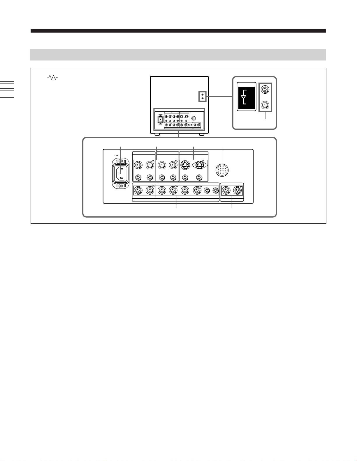
Rear Panel
(The mark indicates automatic termination.)
12 34
AC IN
LINE A LINE B
VIDEO VIDEO
IN OUTIN OUT
LINE C
IN OUT
REMOTE
COMPONENT SDI
IN
OUT
ACTIVE THROUGH
7
IN OUT IN OUT IN OUT
IN OUT IN OUT IN OUT IN OUT IN OUT
R/R–Y G/Y B/B–Y
AUDIOAUDIO AUDIO
RGB/COMPONENT EXT SYNC
1 AC IN socket
Connect the supplied AC power cord to this socket and
to a wall outlet.
2 LINE A, LINE B connectors
Two groups (A and B) of line input connectors for the
composite video and audio signals and their loopthrough output connectors.
To monitor the input signal through these connectors,
set the LINE/RGB selector to the LINE position (light
off) and press the A/RGB or B/COMPONENT selector
(light on).
VIDEO IN (BNC)
Connect to the video output of video equipment, such
as a VCR or a color video camera.
For a loop-through connection, connect to the video
output of another monitor.
VIDEO OUT (BNC)
Loop-through output of the VIDEO IN connector.
Connect to the video input of a VCR or another
monitor.
When the cable is connected to this connector, the
75-ohm termination of the input is automatically
released, and the signal input to the VIDEO IN
connector is output from this connector.
AUDIO
56
AUDIO IN (phono jack)
Connect to the audio output of a VCR or to a
microphone via a suitable microphone amplifier.
For a loop-through connection, connect to the audio
output of another monitor.
AUDIO OUT (phono jack)
Loop-through output of the AUDIO IN connector.
Connect to the audio input of a VCR or another
monitor.
3 LINE C connectors
Y/C IN (4-pin mini-DIN)
Connect to the Y/C separate output of a video camera,
VCR or other video equipment.
For a loop-through connection, connect to the Y/C
separate output of a VCR or another monitor.
Y/C OUT (4-pin mini-DIN)
Loop-through output of the Y/C IN connector.
Connect to the Y/C separate input of a VCR or another
monitor.
When the cable is connected to this connector, the 75ohm termination of the input is automatically released,
and the signal input to the Y/C IN connector is output
from this connector.
6(E)
Page 11

AUDIO IN (phono jack)
Connect to the audio output of a VCR or a microphone
(via a suitable microphone amplifier).
To output the component signal
Connect to the R-Y/Y/B-Y component signal inputs of
a Betacam video recorder, etc.
AUDIO OUT (phono jack)
Loop-through output of the AUDIO IN connector.
Connect to the audio input of a VCR or another
monitor.
4 REMOTE connector (20-pin)
Connect to the tally output of a control console,
special-effect generator, etc. The tally lamp on the
front panel will be turned on and off by the connected
equipment. This connector can also be used for
connecting a remote control unit.
For details on the pin assignment of this connector, see
page 14(E).
5 RGB/COMPONENT connectors
RGB signal or component signal input connectors and
their loop-through output connectors.
To monitor the input signal through these connectors,
set the LINE/RGB selector to the RGB position (light
on), and press the A/RGB or B/COMPONENT
selector (light on).
R/R-Y IN, G/Y IN, B/B-Y IN (BNC)
When the EXT SYNC selector is set to the off position
(light off), the monitor operates on the sync signal
from the G/Y channel.
To monitor the RGB signal
Connect to the analog RGB signal outputs of a video
camera, etc.
AUDIO IN (phono jack)
Connect to the audio output of video equipment when
the analog RGB or component signal is input.
AUDIO OUT (phono jack)
Loop-through outputs of the AUDIO IN connector.
6 EXT SYNC (external sync) connectors
Press the EXT SYNC selector (light on) to use the
sync signal through this connector.
IN (BNC)
When this monitor operates on an external sync signal,
connect the reference signal from a sync generator to
this connector.
OUT (BNC)
Loop-through output of the IN connector. Connect to
the external sync input of video equipment to be
synchronized with this monitor.
When the cable is connected to this connector, the 75ohm termination of the input is automatically released,
and the signal input to the IN connector is output from
this connector.
BVM-20M4DE/14M4DE only
7 COMPONENT SDI IN/OUT connectors
To monitor the input signal through this connector, set
the LINE/RGB selector to the RGB position (light on),
and press the C/SDI selector (light on).
To monitor the component signal
Connect to the R-Y/Y/B-Y component signal outputs
of a Sony Betacam video camera, etc.
R/R-Y OUT, G/Y OUT, B/B-Y OUT (BNC)
Loop-through outputs of the R/R-Y IN, G/Y IN, B/BY IN connectors.
When the cables are connected to these connectors, the
75-ohm termination of the inputs is automatically
released, and the signal inputs to the R/R-Y IN, G/Y
IN, B/B-Y IN connectors are output from these
connectors.
To output the RGB signal
Connect to the analog RGB signal inputs of a video
IN (BNC)
Connect the SERIAL V/A OUT connectors of the
Digital BETACAM VTRs to allow input of SMPTE
259M/CCIR 656-III 4:2:2 serial digital signals.
OUT (BNC)
Outputs the digital signal of the equipment connected
to the COMPONENT SDI IN connector (Active loop-
1)
through
).
We recommend to connect the following cable to this
connectors.
Coaxial cable: 5C-2V (Max. 200 m, 656 feet)
Fujikura Europe Ltd (FEL) or the
equivalent
printer or another monitor.
..........................................................................................................................................................................................................
1) The signal from the IN connector is output through the OUT
connector when the power of the monitor is on.
7(E)
Page 12
Using On-Screen Menus
You can make various settings and adjustments of the
monitor using the on-screen menus.
On-Screen Menu Configuration
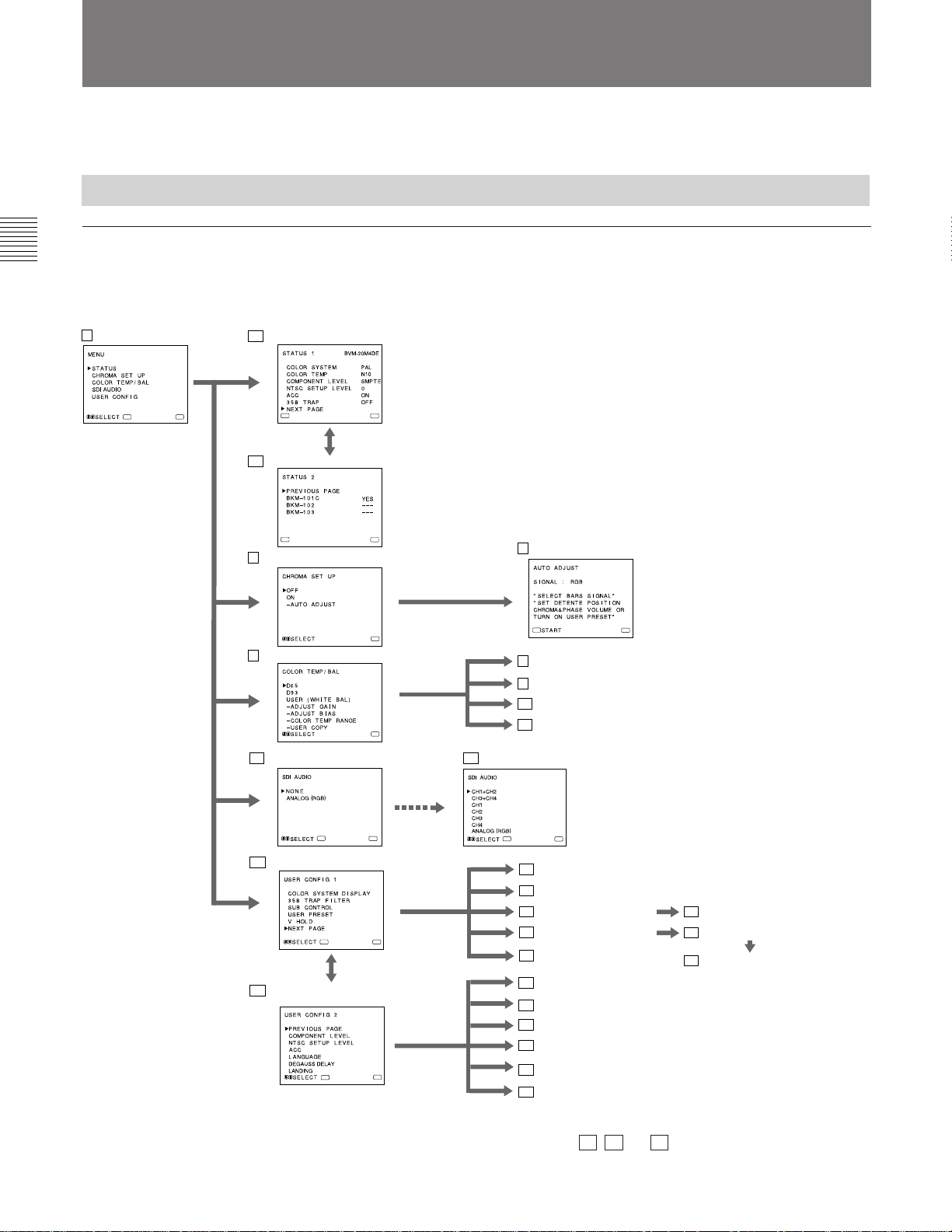
On-screen menu tree-chart
1 Main menu 2a STATUS 1 menu
ENTER
MENU
ENTER
2b STATUS 2 menu
ENTER
3 CHROMA SET UP menu
4 COLOR TEMP/BAL menu
5a SDI AUDIO menu
Main menu
You can enter another menu such as status menu or setting
menu.
Status menu
You can confirm the current settings.
Setting menu
MENU
1)
You can select an item or enter an adjustment screen on this
menu by using the >/+, ./– and ENTER/SELECT buttons.
Adjustment screen
You can make adjustments on this screen. The adjustments
you made remain unchanged until next change even if you
turn off the power.
MENU
MENU
MENU
2)
5b SDI AUDIO menu
7 AUTO ADJUST screen
ENTER
8 ADJUST GAIN screen
9 ADJUST BIAS screen
10 COLOR TEMP RANGE menu
11 USER COPY menu
2)
MENU
ENTER
6a USER CONFIG 1 menu
ENTER
6b USER CONFIG 2 menu
ENTER
MENU
MENU
MENU
ENTER
MENU
12 COLOR SYSTEM DISPLAY menu
13 358 TRAP FILTER menu
14 SUB CONTROL menu
16 USER PRESET menu
19 V HOLD screen
20 COMPONENT LEVEL menu
21 NTSC SETUP LEVEL menu
22 ACC menu
23 LANGUAGE menu
24 DEGAUSS DELAY menu
25 LANDING menu
2)
15 SUB CONTROL screen
17 PRESET ADJUST menu
18 PRESET ADJUST screen
.........................................................................................................................................................................................................
1) BVM-20M4DE/14M4DE: As the Component SDI Kit
BKM-101C is built in these units, the item of BKM101C always appears YES .
2) The menu 5a , 5b and 25 may not be displayed due to the
model.
For details, see pages 10(E) and 11(E).
8(E)
Page 13
Operation through On-Screen Menus
A
M
Operating procedures
Menu operation buttons
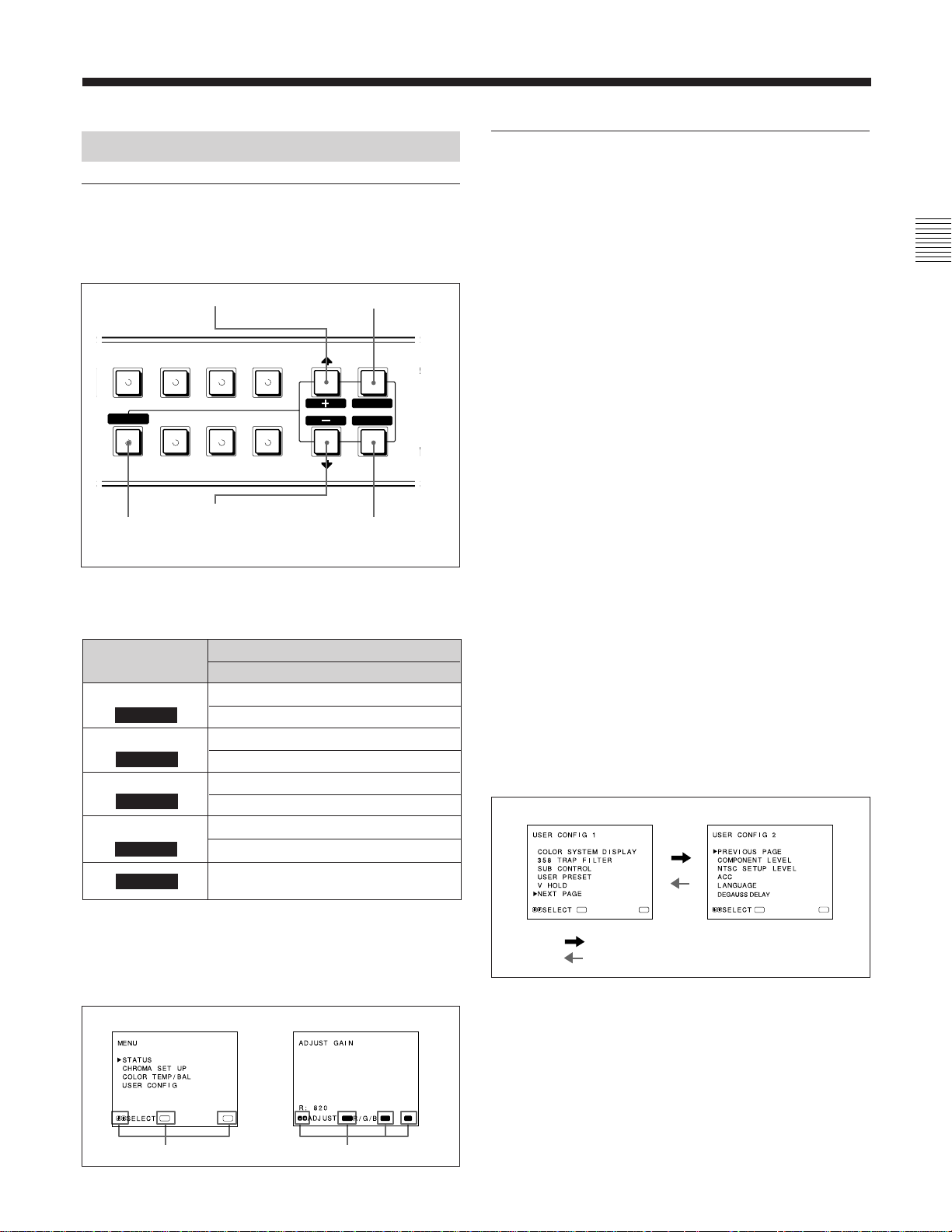
There are five menu operation buttons on the front
panel of the monitor.
3 >/+ button
H/V
EXT
SYNC
16:9
B/
COMPONENT
RESET
BLUE
ONLY
5
RESET button
C/
SDI
UNDER
SCAN
LINE/
RGB
DELAY
4 ./– button
The following table shows how these five buttons
function when using the menus.
To select menu item
To adjust the item selected
return to the previous menu
return to the previous menu
decide a selected item
select an adjustment item
move the cursor (z) upwards
increase selected value
move the cursor (z) downwards
decrease selected value
reset current settings to the factory
setting
1
2
3
4
5
Button
MENU
EXIT
ENTER
SELECT
>
+
.
–
RESET
The buttons that can be used on the menus and
adjustment screens are displayed at the bottom of the
screen. You can perform menu operation using the
displayed buttons.
Menu
Adjustment screen
1
MENU
EXIT
SELECT
ENTER
2
MENU/EXIT
button
ENTER/
SELECT
button
To display the menu, follow this procedure.
1 Press the MENU/EXIT (1) button.
MENU (1 : main menu) appears.
2 Move the cursor (z) to the desired setting menu by
pressing the ./– or >/+ (4, 3) button.
3 Press the ENTER/SELECT (2) button.
The setting menu selected in step 2 appears.
4 Move the cursor (z) to the desired item by
pressing the ./– or >/+ (4, 3) button.
5 Press the ENTER/SELECT (2) button.
The adjustment screen or setting menu selected in
step 4 appears.
For detailed information of menus, see “Functions of OnScreen Menus” on page 10(E).
To display the next (or previous) page of the
menus
Select NEXT PAGE on the menu to display the next
page and PREVIOUS PAGE on the menu to display
the previous page.
MENU 1 MENU 2
MENU
:
When selecting NEXT PAGE
When selecting PREVIOUS PAGE
:
How to display the next or the previous page
ENTERENTER
MENU
ENTER
Usable buttons
Display of the usable menu operation buttons
MENU
SELECT
Usable buttons
RESET
EXIT
9(E)
Page 14
Using On-Screen Menus
To close the menu (to return to the regular
screen)
Each time you press the MENU/EXIT (1) button, the
on-screen menu returns to the one previously
displayed. Press the MENU/EXIT (1) button
repeatedly until the regular screen appears.
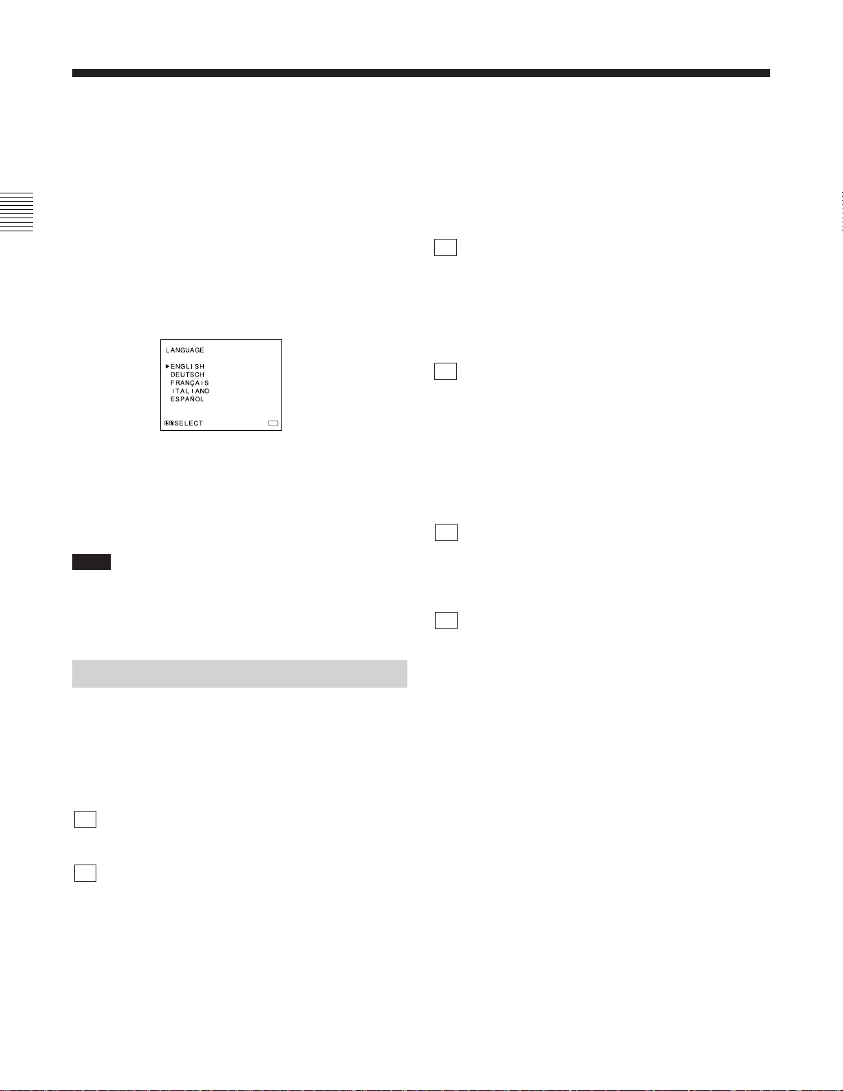
To select the language
For the first time when the monitor is turned on, the
LANGUAGE menu (@£) will appear on the screen.
So, select the language you want to use.
MENU
1 Move the cursor (z) to the desired language by
pressing the ./– or >/+ (4, 3) button.
2 Press the MENU/EXIT (1) button.
Note
Unless you press the MENU/EXIT (1) button in the
procedure above, the LANGUAGE menu will always
appear whenever you turn on the monitor.
Functions of On-Screen Menus
4COLOR TEMP/BAL menu
Select the color temperature from among D65, D93
and USER. USER is set to D65 as the factory setting.
You can adjust or change the color temperature in
USER mode (a measuring instrument is required).
[D65]
5a SDI AUDIO menu (when the BKM-101C is
installed for BVM-20M4E/14M4E)
You can select no sound (NONE) or analog sound
through the AUDIO IN jack in the analog RGB
connectors (ANALOG (RGB)).
No digital sound signals selected. [NONE]
5b SDI AUDIO menu (when the BKM-102 is
installed for BVM-20M4DE/20M4E/14M4DE/
14M4E)
Select the digital sound signals output channels or
analog sound through the AUDIO IN jack in the
analog RGB connectors. When you select
“CH1+CH2”, you can monitor the mixed sound from
channels 1 and 2. [CH1+CH2]
6a USER CONFIG 1 menu
Select an item to adjust on the menus and screens (!™
through !ª). To go to the USER CONFIG 2 menu,
select NEXT PAGE.
6b USER CONFIG 2 menu
Select an item to adjust on the menus and screens (@º
through @∞). To go to the USER CONFIG 1 menu
select PREVIOUS PAGE.
[ ] indicates the factory setting.
1Main menu
Select another menu and press ENTER/SELECT to go
to the menu.
2a STATUS 1 menu
Shows the current settings.
2b STATUS 2 menu
Shows what optional kit is installed in the monitor.
3CHROMA SET UP menu
Select ON on this menu to activate “chroma” and
“phase” (NTSC signal only) adjustments done on the
AUTO ADJUST screen (7). [OFF]
10(E)
7AUTO ADJUST screen
Select the color bar signal (full, SMPTE, EIA) and
press ENTER/SELECT to start automatic “chroma”
and “phase” (NTSC signal only) adjustments.
To activate these adjustments, select ON on the
CHROMA SET UP menu (3).
8ADJUST GAIN screen
Adjust GAIN in USER mode.
9ADJUST BIAS screen
Adjust BIAS in USER mode.
!ºCOLOR TEMP RANGE menu
Select the color temperature range in USER mode.
[5000K-10000K]
Page 15

!¡USER COPY menu
Store the factory setting of D65 or D93 as the value for
USER mode.
!™COLOR SYSTEM DISPLAY menu
Select the period of displaying the color system of the
current input signals. When AUTO is selected, the
color system type being used appears on the screen
each time you change the signal input. [AUTO]
!£358 TRAP FILTER menu
Color spill or color noise may be eliminated if you
select ON (NTSC signal only).
Normally select OFF. [OFF]
!¢SUB CONTROL menu
Select an item (CONTRAST, BRIGHT, CHROMA
and PHASE controls on the front panel) to finely
adjust on the SUB CONTROL screen (!∞).
!∞SUB CONTROL screen
Finely adjust the selected item on the SUB CONTROL
menu (!¢). Each control (CONTRAST, BRIGHT,
CHROMA and PHASE control) has a click position at
the center of its adjustment range. You can adjust the
setting of the click position with this feature.
!§USER PRESET menu
If you select ON on this menu, the REMOTE indicator
lights up and the controls on the front panel do not
work. The monitor operates with the user preset
settings.
To adjust the user preset settings, select the PRESET
ADJUST menu (!¶). [OFF]
!¶PRESET ADJUST menu
You can preset the BRIGHT, CHROMA, PHASE,
CONTRAST, VOLUME, and APERTURE controls to
a desired level and can use these settings by selecting
ON on the USER PRESET menu (!§).
!•PRESET ADJUST screen
Adjust the selected item (BRIGHT, CHROMA,
PHASE, CONTRAST, VOLUME, and APERTURE
control) on the PRESET ADJUST menu (!¶).
!ªV HOLD screen
Adjust the vertical hold if the picture rolls vertically.
@ºCOMPONENT LEVEL menu
Select the component level from among three modes.
N10/SMPTE for 100/0/100/0 signal
BETA 7.5 for 100/7.5/75/7.5 signal
BETA 0 for 100/0/75/0 signal
[N10/SMPTE]
@¡NTSC SETUP LEVEL menu
Select the NTSC setup level from two modes.
The 7.5 setup level is mainly used in north America.
The 0 setup level is mainly used in Europe. [0]
@™ACC menu
Set ACC (Auto Color Control) circuit on or off. When
the fine adjustment is necessary, select OFF on the
ACC menu.
Normally select ON. [ON]
@£LANGUAGE menu
You can select the menu language from among five
languages (English, German, French, Italian, Spanish).
[ENGLISH]
@¢DEGAUSS DELAY menu
Set the time for the degauss function to work after the
power is turned on.
This function can be set at 0 to 99 seconds. [0]
BVM-20M4DE/20M4E only
@∞LANDING screen
If the color is not uniform even after you press the
DEGAUSS button, you can adjust the landing so as to
obtain color uniformity on this screen.
The following two methods are available to adjust the
landing.
When the signals of the horizontal lines are
input and displayed:
Press the ./– or >/+ button until the lines are
displayed on the screen as horizontally as possible.
When the signals of the white color are input
and displayed:
Press the ./– or >/+ button until the white color on
the screen become as uniform as possible.
To reset the setting to standard (00), press the
./– or >/+ buttons at the same time.
Note
When you cannot read the display, select the input that
is not connected.
11(E)
Page 16
Connections
How to Connect the AC Power Cord
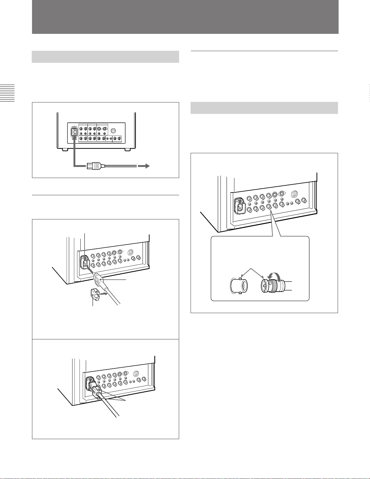
Connect the AC power cord (supplied) to the AC IN
socket and to a wall outlet.
to AC IN
To connect an AC power cord securely
with an AC plug holder
1
AC IN socket
to a wall outlet
To remove the AC power cord
Pull out the AC plug holder while pressing the lock
levers.
How to Connect a Cable to a BNC Connector
Connect a coaxial cable with the BNC plugs to the
BNC connectors on the rear panel as illustrated below.
AC power plug
AC plug holder
Plug the power cord into the AC IN socket. Then, attach
the AC plug holder (supplied) on top of the AC power
cord.
2
Lock levers
Insert the BNC plug into the connector
on the rear panel, matching the slit and
pin, and turn the BNC plug clockwise to
secure the connection.
Slide the AC plug holder over the cord until it locks.
12(E)
Page 17

Specifications
Video signal
Color system PAL, NTSC, SECAM, NTSC4.43
Resolution 800 TV lines
Aperture correction 0 dB to +6 dB
Frequency response
LINE 10 MHz ± 3 dB (Y signal)
RGB 10 MHz ± 3 dB
Synchronization AFC time constant 1.0 msec.
Picture performance
Normal scan 2 % over scan of CRT effective screen
area
Preset luminance 90 cd/m2 (when the BRIGHT and
CONTRAST controls are set to the
center click position)
Under scan 5 % underscan of CRT effective screen
area
H. linearity BVM-20M4DE/20M4E:
Less than 5.0 % (typical)
BVM-14M4DE/14M4E:
Less than 4.0 % (typical)
V. linearity BVM-20M4DE/20M4E:
Less than 5.0 % (typical)
BVM-14M4DE/14M4E:
Less than 4.0 % (typical)
Convergence
Central area: BVM-20M4DE/20M4E:
Less than 0.5 mm (typical)
BVM-14M4DE/14M4E:
Less than 0.4 mm (typical)
Peripheral area: BVM-20M4DE/20M4E:
Less than 0.7 mm (typical)
BVM-14M4DE/14M4E:
Less than 0.5 mm (typical)
Raster size stability H: 1.0%, V: 1.5%
High voltage regulation
BVM-20M4DE/20M4E: 4.0 %
BVM-14M4DE/14M4E: 3.5 %
Color temperature D65/D93, selectable
USER (3,200K–10,000K, factory
setting is D65)
Inputs
LINE A/B
VIDEO IN BNC connector (×2), 1Vp-p ±6 dB,
sync negative
AUDIO IN Phono jack (×2), –5 dBua), more than
47 kilo-ohms
LINE C
Y/C IN 4-pin mini-DIN (×1)
See the pin assignment on page 14(E).
AUDIO IN Phono jack (×1), –5 dBua), more than
47 kilo-ohms
RGB/COMPONENT
R/R-Y,G/Y,B/B-Y IN: BNC connector (×3)
R, G, B channels: 0.7 Vp-p, ±6 dB
Sync on green: 0.3 Vp-p, negative
R-Y, B-Y channels: 0.7 Vp-p, ±6 dB
Y channel: 0.7 Vp-p, ±6 dB
(Standard color bar signal of 75%
chrominance)
AUDIO IN Phono jack (×1), –5 dBu1), more than
47 kilo-ohms
EXT SYNC IN BNC connector (×1)
4 Vp-p, ±6 dB, sync negative
COMPONENT SDI IN (BVM-20M4DE/14M4DE only)
BNC connector (×1)
Serial digital (270M bits/s)
SMPTE 259M/CCIR 656-III
Quantization: 10 bits/sample
Frequency responce:
Y: 5.75 MHz, –3 dB
R-Y/B-Y: 2.75 MHz, –3 dB
REMOTE 20-pin connector (×1)
See the pin assignment on page 14(E).
Outputs
LINE A/B
VIDEO OUT BNC connector (×2) loop-through,
Automatic 75 ohms termination
AUDIO OUT Phono jack (×2) loop-through
LINE C
Y/C OUT 4-pin mini-DIN (×1) loop-through,
Automatic 75 ohms termination
AUDIO OUT Phono jack (×1) loop-through
RGB/COMPONENT
R/R-Y,G/Y,B/B-Y OUT
BNC connector (×3)
loop-through
Automatic 75 ohms termination
AUDIO OUT Phono jack (×1) loop-through
EXT SYNC OUT BNC connector (×1)
Automatic 75 ohms termination
COMPONENT SDI OUT (BVM-20M4DE/14M4DE only)
BNC connector (×1)
Active loop-through output
Serial digital (270M bits/s)
SMPTE 259M/CCIR 656-III
Speaker output Output level: 0.8 W
................................................................................................................................
1) 0 dBu = 0.775 Vr.m.s.
13(E)
Page 18
Specifications
General
CRT EBU phosphor
Power consumption BVM-20M4DE/20M4E: 140 W
BVM-14M4DE/14M4E: 99 W
Power requirements 100 to 240 V AC, 50/60Hz
Peak inrush current BVM-20M4DE/20M4E:
(1) Power ON, current probe method:
18 A (240 V)
(2) Hot switching inrush current,
measured in accordance with
European standard EN55103-1:
7 A (230 V)
BVM-14M4DE/14M4E:
(1) Power ON, current probe method:
18 A (240 V)
(2) Hot switching inrush current,
measured in accordance with
European standard EN55103-1:
4 A (230 V)
Operating temperature
0 to +35°C (32 to 95°F)
Operating humidity 0 to 90% (no condensation)
Dimensions (w/h/d) BVM-20M4DE/20M4E:
Approx. 450 × 458 × 503 mm
(173⁄4 × 181⁄8 × 197⁄8 inches)
BVM-14M4DE/14M4E:
Approx. 346 × 340 × 431 mm
(135⁄8 × 131⁄2 × 17 inches)
not incl. projecting parts and controls
Mass BVM-20M4DE/20M4E:
Approx. 31kg (68 lb 5 oz)
BVM-14M4DE/14M4E:
Approx. 18kg (39 lb 11 oz)
Accessory supplied AC power cord (1), AC plug holder
(1), Tally label (1), Cable with a 20-pin
connector (1), Operation Manual (1)
Design and specifications are subject to change
without notice.
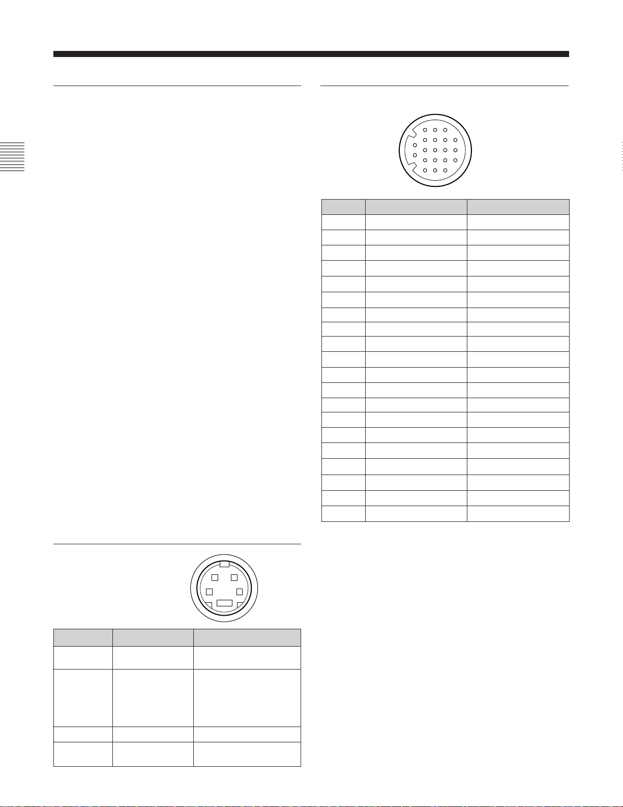
REMOTE connector (20-pin)
3
8
13
4
9
14
1
2
Pin No.
1
2
3
4
5
6
7
8
9
10
11
12
13
14
15
16
17
18
19
20
Signal
Blue only
H/V DELAY
MAIN/SUB*
EXT SYNC
DEGAUSS
R ch ON/OFF*
TALLY
LINE B
GND
GND
GND
GND
LINE A
LINE/RGB
GND
L ch ON/OFF*
REMOTE
LINE C
UNDER SCAN
16:9
(* For digital audio control)
18
5
10
15
19
6
11
16
20
7
12
17
Wire color
Brown
Red
Orange
Yellow
Green
Blue
Purple
Grey
White
Black
Pink
Light Blue
Spiral Orange
Spiral Yellow
Spiral Green
Spiral Blue
Spiral Purple
Spiral Grey
Spiral Pink
Spiral Light Blue
Pin assignment
Y/C IN connector
(4-pin mini-DIN)
Pin No.
1
2
3
4
Signal
Y-input
CHROMA
subcarrier-input
GND for Y-input
GND for
CHROMA-input
14(E)
21
34
*
Description
1 Vp-p, sync negative,
75 ohms
300m Vp-p (PAL)/286m
Vp-p (NTSC), burst
Delay time between Y
and C: within 0 ± 100
nsec., 75 ohms
GND
GND
How to connect a remote control unit
Connect No.17 pin to one of the GND pins (No.9 – 12,
and 15), then connect pins for the functions you want
to use to other GND pins (No.9 – 12, and 15).
How to light the tally lamp
Connect No.7 pin to one of the GND pins (No.9 – 12,
and 15).
Page 19

15(E)
Page 20
Italiano
A vvertenze
ATTENZIONE
Per evitare incendi o cortocircuiti,
l’apparecchio non deve essere esposto
alla pioggia o all’umidità.
All’interno del televisore sono presenti
tensioni pericolosamente alte. Non aprire
l’apparecchio. Per le riparazioni, rivolgersi
esclusivamente a personale specializzato.
Nel caso di malfunzionamenti o di necessarie
riparazioni dell’apparecchio, consultare un rivenditore
autorizzato Sony.
Per i clienti in Europa
Questo prodotto recante il marchio CE è conforme sia
alla direttiva sulla compatibilità elettromagnetica (EMC)
(89/336/CEE) che alla direttiva sulle basse tensioni
(73/23/CEE) emesse dalla Commissione della
Comunità Europea.
La conformità a queste direttive implica la conformità
alle seguenti normative europee:
• EN60950: Sicurezza dei prodotti
• EN55103-1: Interferenza elettromagnetica
(Emissione)
• EN55103-2: Sensibilità ai disturbi elettromagnetici
(Immunità)
Questo prodotto è destinato all’uso nei seguenti
ambienti elettromagnetici:
E1 (residenziali), E2 (commerciali e industriali leggeri),
E3 (esterni urbani) e E4 (ambienti EMC controllati, ad
esempio studi televisivi).
I presenti prodotti sono stati progettati per l’utilizzo
negli ambienti da E1 a E4. Durante la tensione EMC, il
grado di prestazione (valutato in base a ITU/R 562-3 e
ITU/R 500-4) potrebbe diminuire, come mostrato nella
tabella 1. In assenza di tensione EMC, il grado di
prestazione torna al livello di funzionamento completo.
Norme di sicurezza
• Alimentare l’apparecchio solo tramite le fonti di
alimentazione specificate nella sezione
“Caratteristiche tecniche”.
• La targhetta recante i dati relativi alla tensione, al
consumo, ecc., è posta sulla parte posteriore
dell’apparecchio.
• Qualora solidi o liquidi dovessero penetrare
nell’apparecchio, scollegarlo e rivolgersi a personale
qualificato prima di utilizzarlo nuovamente.
• Non lasciar cadere o collocare oggetti pesanti sul
cavo di alimentazione. Qualora il cavo di
alimentazione fosse danneggiato, spegnere
immediatamente l’apparecchio. È pericoloso
utilizzare un apparecchio con un cavo di
alimentazione danneggiato.
• Scollegare l’apparecchio dalla presa a muro se non
viene utilizzato per diversi giorni consecutivi.
• Scollegando il cavo dalla presa CA, accertarsi di
afferrare la spina e di non tirare il cavo.
• La presa a muro deve trovarsi non lontano
dall’apparecchio ed essere facilmente accessibile.
Installazione
• Consentire una buona circolazione d’aria per
prevenire il surriscaldamento interno
dell’apparecchio.
Non collocare l’apparecchio su superfici morbide
(coperte, tessuti, ecc.) o vicino a tendaggi o altri
materiali che possano ostruire i fori di ventilazione.
• Non collocare l’apparecchio vicino a fonti di calore,
come termosifoni o condotti d’aria calda, in luoghi
polverosi o in luoghi esposti alla luce diretta del sole,
a scosse o a vibrazioni meccaniche.
Tabella 1
Frequenza Livello
Monitor da 14” 24-40 MHz 4-3
190-290, 360 e 4
420 MHz
Monitor da 20” 35-50 MHz 1
100 e 420 MHz 4
Manutenzione
Per mantenere l’apparecchio come nuovo, pulirlo
periodicamente con una soluzione detergente delicata.
Non utilizzare mai solventi potenti come diluente o
benzene, o detergenti abrasivi, poiché
danneggerebbero le parti esterne. Per precauzione,
scollegare l’apparecchio prima di pulirlo.
Page 21
Indice
Italiano
Imballaggio
Non gettare il cartone ed i vari materiali per
l’imballaggio, in quanto costituiscono il contenitore
più adatto per trasportare l’apparecchio. Dovendo
trasportare l’apparecchio, imballarlo come illustrato
sullo scatolone.
Per ulteriori informazioni riguardanti il presente
apparecchio, rivolgersi al più vicino rivenditore
autorizzato Sony.
Caratteristiche ......................................................2(I)
Posizione e funzioni delle parti e dei comandi ...4(I)
Pannello anteriore.........................................4(I)
Pannello posteriore....................................... 6(I)
Uso dei menu a schermo.......................................8(I)
Configurazione dei menu a schermo............8(I)
Operazioni tramite i menu a schermo .......... 9(I)
Funzioni dei menu a schermo.....................10(I)
Collegamenti .......................................................12(I)
Collegamento del cavo di
alimentazione CA..................................12(I)
Collegamento di un cavo ad un
connettore BNC.....................................12(I)
Caratteristiche tecniche .....................................13(I)
Il manuale
Prima di usare l’apparecchio, leggere con attenzione
questo manuale e conservarlo per riferimenti futuri.
Le istruzioni contenute nel presente manuale, se non
indicato diversamente, si riferiscono ai modelli
riportati sotto.
Qualora le istruzioni siano differenti per i diversi
modelli, questo viene chiaramente indicato nel
presente manuale.
• BVM-14M4DE/14M4E (monitor 14 pollici)
• BVM-20M4DE/20M4E (monitor 20 pollici)
Le illustrazioni relative al monitor del video si
riferiscono al modello BVM-14M4DE.
1(I)
.................
Page 22

Caratteristiche
Immagine
Cinescopio Trinitron1) HR (alta risoluzione)
Il cinescopio Trinitron HR fornisce un’immagine ad
alta risoluzione. La risoluzione orizzontale è superiore
a 800 righe TV al centro dell’immagine.
Filtro a pettine
Durante la ricezione di segnali video NTSC, viene
attivato un filtro a pettine per effettuare la separazione
dei segnali Y/C in modo più accurato. Questo
contribuisce a ridurre la perdita di risoluzione e il
verificarsi di fenomeni di interferenza di colore e
luminanza.
Circuito BCF
Il circuito BCF di cui è dotato l’apparecchio assicura
un bilanciamento del bianco stabile.
Sistema a quattro colori disponibile
Il monitor può riprodurre segnali in NTSC, PAL,
SECAM e NTSC
viene selezionato automaticamente.
Modo solo blu
Nel modo solo blu si ottiene una visualizzazione
apparentemente monocromatica con tutti e tre i catodi
pilotati con un segnale blu. Questo facilita la
regolazione della fase e della saturazione del colore e
l’osservazione dei disturbi del videoregistratore.
2)
4,43
. Il sistema di colore appropriato
Ingressi
Connettori di ingresso/uscita3) COMPONENT
4)
SDI
per il modello BVM-20M4DE/14M4DE
Questi connettori consentono l’entrata e l’uscita del
segnale digitale seriale SMPTE 259M 4:2:2 da un
videoregistratore digitale.
Quando si installa un kit SDI componente <Audio>
BKM-102 (non in dotazione), è possibile controllare il
suono dai segnali di ingresso digitale seriale con
l’immagine.
Connettori di ingresso RGB analogico/
componente
Questi connettori consentono l’ingresso dei segnali di
RGB analogico o di componente (Y, R-Y e B-Y)
provenienti da un apparecchio video.
Connettori d’ingresso Y/C
Il segnale video, composto dal segnale di crominanza
(C) e dal segnale di luminanza (Y), può essere
immesso attraverso questo connettore, che elimina
l’interferenza fra i due segnali, caratteristica dei
segnali video compositi, garantendo così la qualità
dell’immagine.
Ingresso di sincronizzazione esterna
Quando è premuto il tasto EXT SYNC, il monitor può
essere attivato sul segnale di sincronizzazione
proveniente da un generatore di sincronizzazione
esterno.
Terminazione automatica
(solo su connettori contrassegnati dal
simbolo
)
Il connettore d’ingresso ha una terminazione interna di
75 ohm se ai connettori esterni a ciclo aperto non è
collegato alcun cavo. Se ad un connettore esterno è
collegato un cavo, la terminazione di 75 ohm viene
automaticamente disattivata.
.................................................................................................................................................................................................................................
1) Trinitron è un marchio registrato della Sony
Corporation.
2) Il sistema NTSC4,43 utilizza un sistema di colori
NTSC nel quale la frequenza sottoportante passa a
4,43 MHz. Quando un programma registrato su un
sistema NTSC viene riprodotto con un
videoregistratore Trident (PAL, SECAM, NTSC4,43),
viene emesso il segnale NTSC4,43.
3) Il kit SDI componente BKM-101C (per video) è
incorporato nel modello BVM-20M4DE/14M4DE.
4) SDI: Serial Digital Interface, interfaccia digitale seriale
2(I)
Page 23
Funzioni
Cinque lingue disponibili
I menu sono disponibili in cinque lingue.
Modo di sottoscansione
In modo di sottoscansione è possibile controllare il
segnale che viene normalmente analizzato fuori dallo
schermo.
Nota
Quando il monitor è in modo di sottoscansione, è
possibile che sul bordo superiore dello schermo
appaiano le righe scure della scansione RGB. Queste
righe sono generate da un segnale di prova interno e
non dal segnale in ingresso.
Modo di ritardo orizzontale/verticale
Nel modo di ritardo orizzontale/verticale è possibile
controllare simultaneamente i segnali di
sincronizzazione orizzontali e verticali.
Smagnetizzazione automatica/manuale
La smagnetizzazione dello schermo può essere
eseguita automaticamente quando si accende
l’apparecchio, oppure manualmente premendo il tasto
DEGAUSS.
Menu a video
I menu a video permettono di impostare la temperatura
del colore ed altri parametri.
Kit di montaggio per il rack EIA da 19” in
dotazione
Per il montaggio del rack, utilizzare un kit appropriato.
Europa MB-502C (da 14”) / SLR-103C (da
20”)
Qualsiasi altra area MB-502B (da 14”) /SLR-103A (da
20”)
Per istruzioni dettagliate sul montaggio, vedere il manuale
d’istruzioni in dotazione con il kit della staffa di montaggio
o il kit della guida a scorrimento.
Kit SDI (Serial Digital Interface) (per audio) per
il modello BVM-20M4DE/14M4DE
Utilizzando il kit SDI componente BKM-102 ( per
audio, opzionale), è possibile controllare il segnale
audio-digitale seriale SMPTE 259M 4:2:2 da un
videoregistratore digitale VCR con l’immagine.
Kit di interfaccia digitale seriale SDI per BVM20M4E/14M4E
Con l’uso dei seguenti kit SDI il monitor può
visualizzare il segnale digitale seriale SMPTE 259M
4:2:2 proveniente da un videoregistratore digitale (ad
esempio dal videoregistratore Sony 4:2:2).
– BKM-101C:kit SDI componente (per video)
– BKM-102: kit SDI componente (per audio)
Nota
Quando il numero seriale del BKM-101C che si
desidera collegare è inferiore a 2.010.000 sarà
necessario un cablaggio opzionale (numero di parte 1900-230-35).
Kit di interfaccia seriale remota
Utilizzando il kit di interfaccia seriale remota BKM103, il monitor può essere controllato dai personal
computer tramite l’interfaccia seriale RS-422A.
3(I)
Page 24
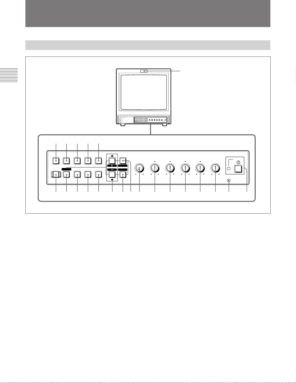
Posizione e funzioni delle parti e dei comandi
Pannello anteriore
1
!ª
LINE/
RGB
H/V
DELAY
!¢!∞!§
!•
EXT
SYNC
16:9
!£
MENU
EXIT
SELECT
ENTER
!¡!™
APERTURE
MIN
@º@¡@™
COMPONENT
RGB
DEGAUSS UNDER
RESET
BLUE
ONLY
SDI
SCAN
C/
B/
A/
!¶
1 Spia di controllo
Si accende quando viene selezionata la videocamera
collegata a questo monitor, indicando che l’immagine
è in corso di registrazione.
Per informazioni su come accendere la spida di controllo,
vedere a pagina 14(I).
2 Interruttore e indicatore di accensione
(POWER)
Premere l’interruttore per accendere il monitor. La spia
verde dell’indicatore si accende.
3 Indicatore di comando a distanza
(REMOTE)
Si accende quando l’opzione PRESELEZ UTENTE
(vedere a pagina 11(I)) del menu viene impostata su SI
o quando si collega uno dei cavi in dotazione al
connettore REMOTE. Quando questo indicatore è
acceso, i comandi del pannello anteriore sono
disabilitati.
Per informazioni su come effettuare il collegamento del
cavo, vedere a pagina 14(I).
VOLUME
POWER
REMOTE
MAX
–+
MIN
CONTRAST
PHASECHROMABRIGHT
MAX
PUR GRN MIN MAX MIN MAX
4 Comando di regolazione del volume
(VOLUME)
Ruotare in senso orario o antiorario per ottenere il
volume desiderato.
5 Comando di regolazione del contrasto
(CONTRAST)
Ruotare in senso orario per accentuare il contrasto e in
senso antiorario per attenuarlo.
6 Comando di regolazione della fase (PHASE)
Questo comando ha effetto solo se si utilizzano i
sistemi di colore NTSC e NTSC
4,43. Ruotare in senso
orario per accentuare i toni verdastri nel colore della
pelle e in senso antiorario per accentuare i toni
violacei.
7 Comando di regolazione del colore
(CHROMA)
Ruotare in senso orario per aumentare l’intensità del
colore e in senso antiorario per ridurla.
8 Comando di regolazione della luminosità
(BRIGHT)
Ruotare in senso orario per aumentare la luminosità e
in senso antiorario per ridurla.
234 567890
4(I)
Page 25

9 Comando di regolazione dell’apertura
(APERTURE)
Ruotare in senso orario per aumentare la nitidezza e in
senso antiorario per ridurla.
!¶ Tasto di smagnetizzazione (DEGAUSS)
Premere questo tasto brevemente per smagnetizzare lo
schermo. Attendere almeno 10 minuti prima di
riutilizzare il tasto.
Nota
Le impostazioni dei comandi PHASE (6), CHROMA
(7) e APERTURE (9) non hanno effetto sulla
visualizzazione dei segnali RGB.
0 Tasto di visualizzazione del menu (MENU/
EXIT)
Premere questo tasto per visualizzare il menu.
Quando un menu è visualizzato sul display, si può
ritornare al menu precedente premendo questo tasto.
!¡ Tasto di selezione/conferma (ENTER/
SELECT)
Premere questo tasto per confermare la selezione di
un’opzione del menu.
!™ Tasti >/+ e ./–
Premere questi tasti per spostare il cursore (z) o per
regolare il valore selezionato nel menu.
!£ Selettore 16:9
Premere questo tasto (indicatore acceso) per
selezionare il segnale dell’immagine 16:9.
!¢ Selettore del ritardo orizzontale/verticale
(H/V DELAY)
Premere questo tasto (indicatore acceso) per osservare
simultaneamente i segnali di sincronizzazione
orizzontali e verticali.
Il segnale di sincronizzazione orizzontale viene
mostrato nel quarto sinistro dello schermo; il segnale
di sincronizzazione verticale viene visualizzato vicino
al centro dello schermo.
!∞ Selettore di sottoscansione (UNDER SCAN)
Premere questo tasto (indicatore acceso) per avviare la
sottoscansione. Le dimensioni dell’immagine
visualizzata vengono ridotte del 5% circa, rendendo
visibili i quattro angoli dell’area di scansione.
!§ Selettore del modo solo blu (BLUE ONLY) e
tasto RESET
• Come per il selettore BLUE ONLY, premere questo
tasto (indicatore acceso) per disattivare i segnali
rosso e verde. Sullo schermo viene visualizzato solo
un segnale blu, come immagine apparentemente
monocromatica. Questo facilita la regolazione dei
comandi di colore e di fase e l’osservazione dei
disturbi del videoregistratore.
(La regolazione della fase è possibile solo per i
segnali NTSC.)
• Come per il tasto RESET, è possibile ripristinare le
impostazioni del menu, premendo questo tasto
quando sul display è visualizzato un menu.
!• Selettore di sincronizzazione esterna (EXT
SYNC)
• Impostare questo selettore in posizione Off
(indicatore spento) per far funzionare il monitor con
il segnale di sincronizzazione dal segnale video
visualizzato.
• Impostare questo selettore in posizione On
(indicatore acceso) per far funzionare il monitor con
il segnale di sincronizzazione esterno tramite il
connettore EXT SYNC.
!ª Selettore dell’ingresso (LINE/RGB)
Premere questo selettore per selezionare l’ingresso da
controllare.
• Impostare questo selettore in posizione Off
(indicatore spento) per controllare il segnale tramite i
connettori LINE A, LINE B, LINE C.
• Impostare questo selettore in posizione On
(indicatore acceso) per controllare il segnale tramite i
connettori RGB/COMPONENT.
@º Selettore C/SDI
• Quando il selettore dell’ingresso LINE/RGB è
impostato su LINE (indicatore spento) premendo
questo tasto (interruttore acceso) viene controllato il
segnale tramite i connettori LINE C.
• Quando il selettore dell’ingresso LINE/RGB è
impostato su RGB (indicatore acceso), premendo
questo tasto (interruttore acceso) viene controllato il
segnale SDI (sono necessari kit opzionali).
@¡ Selettore B/COMPONENT
• Quando il selettore dell’ingresso LINE/RGB è
impostato su LINE (indicatore spento) premendo
questo tasto (interruttore acceso) viene controllato il
segnale tramite i connettori LINE B.
• Quando il selettore dell’ingresso LINE/RGB è
impostato su RGB (indicatore acceso), premendo
questo tasto (interruttore acceso) viene controllato il
segnale componente tramite i connettori RGB/
COMPONENT.
@™ Selettore A/RGB
• Quando il selettore dell’ingresso LINE/RGB è
impostato su LINE (indicatore spento) premendo
questo tasto (interruttore acceso) viene controllato il
segnale tramite i connettori LINE A.
• Quando il selettore dell’ingresso LINE/RGB è
impostato su RGB (indicatore acceso), premendo
questo tasto (interruttore acceso) viene controllato il
segnale RGB attraverso i connettori RGB/
COMPONENT.
5(I)
Page 26
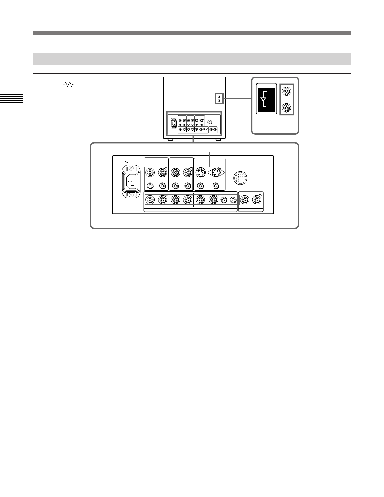
Posizione e funzioni delle parti e dei comandi
Pannello posteriore
(Il simbolo indica la terminazione automatica.)
12 34
AC IN
1 Presa di alimentazione (AC IN)
Collegare il cavo di alimentazione in dotazione a
questa presa e a una presa di rete.
2 Connettori di ingresso in linea (LINE A,
LINE B)
Due gruppi (A e B) di connettori di ingresso in linea
per i segnali video e audio compositi, con i rispettivi
connettori di uscita per ciclo aperto.
Per controllare il segnale di ingresso ricevuto
attraverso questi connettori, tenere il selettore LINE/
RGB in posizione LINE (indicatore spento) e premere
il selettore A/RGB o B/COMPONENT (indicatore
acceso).
VIDEO IN (tipo BNC)
Collegare questo connettore all’uscita video di un
apparecchio video, ad esempio un videoregistratore o
una videocamera a colori. Per il collegamento a ciclo
aperto, collegarlo all’uscita video di un altro monitor.
VIDEO OUT (tipo BNC)
Uscita per ciclo aperto del connettore VIDEO IN.
Collegare all’ingresso video di un videoregistratore o
di un altro monitor.
Quando a questo connettore è collegato un cavo, la
terminazione a 75 ohm dell’ingresso viene rilasciata
automaticamente e il segnale in ingresso al connettore
VIDEO IN viene emesso da questo connettore.
LINE A LINE B
VIDEO VIDEO
IN OUT IN OUT IN OUT
IN OUT IN OUT IN OUT IN OUT IN OUT
R/R–Y G/Y B/B–Y
IN OUTIN OUT
COMPONENT SDI
IN
OUT
ACTIVE THROUGH
LINE C
IN OUT
AUDIOAUDIO AUDIO
RGB/COMPONENT EXT SYNC
REMOTE
AUDIO
56
AUDIO IN (presa fono)
Collegare all’uscita audio di un videoregistratore o a
un microfono tramite un amplificatore per microfono
adatto. Per un collegamento a ciclo aperto, collegare
all’uscita audio di un altro monitor.
AUDIO OUT (presa fono)
Uscita per ciclo aperto del connettore AUDIO IN.
Collegare all’ingresso audio di un videoregistratore o
di un altro monitor.
3 Connettori LINE C
Y/C IN (mini DIN a 4 piedini)
Collegare all’uscita Y/C separata di una videocamera,
di un videoregistratore o di un altro apparecchio video.
Per un ottenere collegamento ad anello, eseguire il
collegamento su un’uscita a parte Y/C del
videoregistratore o su un altro monitor.
Y/C OUT (mini DIN a 4 piedini)
Uscita per ciclo aperto del connettore Y/C IN.
Collegare all’ingresso Y/C separato di un
videoregistratore o di un altro monitor.
Quando a questo connettore è collegato un cavo, la
terminazione a 75 ohm dell’ingresso viene rilasciata
automaticamente e il segnale in ingresso al connettore
Y/C IN viene emesso da questo connettore.
7
6(I)
Page 27

AUDIO IN (presa fono)
Collegare all’uscita audio di un videoregistratore o a
un microfono (tramite un amplificatore per microfono
adeguato).
AUDIO OUT (presa fono)
Uscita per ciclo aperto del connettore AUDIO IN.
Collegare all’ingresso audio di un videoregistratore o
di un altro monitor.
4 Connettore REMOTE (20 piedini)
Per emettere il segnale di componente
Collegare agli ingressi per il segnale componente
R-Y/Y/B-Y di un videoregistratore Betacam.
AUDIO IN (presa fono)
Collegare all’uscita audio di un apparecchio video
quando viene ricevuto un segnale RGB analogico o un
segnale componente.
AUDIO OUT (presa fono)
Uscite per ciclo aperto del connettore AUDIO IN.
Collegare all’uscita di controllo di una console, di un
generatore di effetti speciali, ecc. La spia di controllo
posta sul pannello anteriore verrà accesa e spenta
dall’apparecchiatura collegata.
Questo connettore può essere utilizzato anche per
collegare un telecomando.
Per informazioni dettagliate sull’assegnazione dei piedini di
questo connettore, vedere pagina 14(I).
6 Connettori di sincronizzazione esterna (EXT
SYNC)
Per utilizzare il segnale di sincronizzazione ricevuto
tramite questo connettore, premere il selettore EXT
SYNC (indicatore acceso).
IN (tipo BNC)
Per utilizzare un segnale di sincronizzazione esterno,
collegare a questo connettore il segnale di riferimento
5 Connettori RGB/COMPONENT
Connettori di ingresso per segnali RGB e segnali
componenti e rispettivi connettori di uscita per ciclo
aperto.
Per controllare il segnale in ingresso proveniente da
questi connettori, tenere il selettore LINE/RGB in
posizione RGB (indicatore acceso) e premere il
selettore A/RGB o B/COMPONENT (indicatore
acceso) sul pannello anteriore.
proveniente da un generatore di sincronizzazione.
OUT (tipo BNC)
Uscita per ciclo aperto del connettore IN. Collegare
all’ingresso di sincronizzazione esterno
dell’apparecchio video da sincronizzare con il monitor.
Quando a questo connettore è collegato un cavo, la
terminazione a 75 ohm dell’ingresso viene rilasciata
automaticamente e il segnale inviato al connettore IN
viene emesso da questo connettore.
R/R-Y IN, G/Y IN, B/B-Y IN (tipo BNC)
Quando il selettore EXT SYNC è in posizione esterna
(indicatore spento), il monitor utilizza il segnale di
sincronizzazione proveniente dal canale G/Y.
Per controllare il segnale RGB
Collegare alle uscite del segnale RGB analogico di una
videocamera.
Per controllare il segnale componente
Collegare alle uscite del segnale componente R-Y/Y/
B-Y di una videocamera Sony Betacam.
Solo per il modello BVM-20M4DE/14M4DE
7 Connettori COMPONENT SDI IN/OUT
Per controllare il segnale di ingresso tramite questo
connettore, impostare il selettore LINE/RGB sulla
posizione RGB (luce accesa) e premere il selettore C/
SDI (luce accesa).
IN (tipo BNC)
Collegare i connettori SERIAL V/A OUT del
videoregistratore Digital BETACAM per consentire
l’ingresso dei segnali digitali seriali SMPTE 259M/
R/R-Y OUT, G/Y OUT, B/B-Y OUT (tipo BNC)
CCIR 656-III 4:2:2.
Uscite per ciclo aperto dei connettori R/R-Y IN, G/Y
IN, B/B-Y IN.
Quando a questi connettori è collegato un cavo, la
terminazione a 75 ohm degli ingressi viene
automaticamente rilasciata, e i segnali in ingresso
diretti ai connettori R/R-Y IN, G/Y IN, B/B-Y IN
vengono emessi da questi connettori.
Per emettere il segnale RGB
Collegare agli ingressi per il segnale RGB analogico di
OUT (tipo BNC)
Emette il segnale digitale dell’apparecchio collegato al
connettore COMPONENT SDI IN (ciclo aperto
1)
attivo
).
Si consiglia di collegare il seguente cavo a questi
connettori.
Cavo coassiale: 5C-2V (max. 200 m)
Fujikura Europe Ltd (FEL) o equivalente
una videostampante o di un altro monitor.
.................................................................................................................................................................................................................................
1) Il segnale dal connettore IN viene emesso dal connettore
OUT quando il monitor è acceso.
7(I)
Page 28
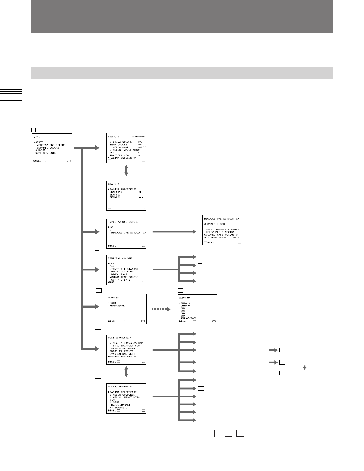
Uso dei menu a schermo
È possibile effettuare impostazioni e regolazioni del
monitor di vario tipo utilizzando i menu a schermo.
Configurazione dei menu a schermo
Diagramma ad albero dei menu a schermo
1 Menu principale 2a Menu STATO 1
ENTER
MENU
ENTER
2b Menu STATO 2
ENTER
3 Menu IMPOSTAZIONE COLORE
4 Menu TEMP/BIL COLORE
5a AUDIO SDI menu
MENU
1)
MENU
MENU
MENU
2)
Menu principale
È possibile inserire un altro menu quale il menu
Stato o Impostazione.
Menu Stato
È possibile confermare le impostazioni correnti.
Menu Impostazione
È possibile selezionare una voce o inserire uno
schermo di regolazione su questo menu usando i
tasti >/+, ./– e ENTER/SELECT.
Schermo di regolazione
Su questo schermo è possibile eseguire delle
regolazioni. Le regolazioni effettuate rimangono tali
e quali fino alla successiva modifica, anche se
l’apparecchio viene spento.
7 Videata REGOLAZIONE AUTOMATICA
ENTER
8 Videata REGOL GUADAGNO
9 Videata REGOL BIAS
10 Menu GAMMA TEMP COLORE
11 Menu COPIA UTENTE
5b AUDIO SDI menu
2)
MENU
ENTER
6a Menu CONFIG UTENTE 1
ENTER
6b Menu CONFIG UTENTE 2
ENTER
MENU
MENU
MENU
ENTER
MENU
12 Menu VISUAL SISTEMA COLORE
13 Menu FILTRO TRAPPOLA 358
14 Menu COMANDO SECONDARIO
16 Menu PRESELEZ UTENTE
19 Videata SYNCRONISMO VERT
20 Menu LIVELLO COMPONENT
21 Menu LIVELLO IMPOST NTSC
22 Menu ACC
23 Menu LINGUA
24 Menu RITARDO SMAGNET.
25 Menu ATTERRAGGIO
2)
15 Videata COMANDO
SECONDARIO
17 Menu PRESELEZ REGOL
18 Videata PRESELEZ REGOL
.................................................................................................................................................................................................................................
1) BVM-20M4DE/14M4DE: Poiché il kit SDI
componente BKM-101C è incorporato nell’unità,
l’opzione di BKM-101C è sempre SI.
2) Il menu 5a , 5b e 25 potrebbero non venir visualizzati a
seconda del modello.
Per ulteriori informazioni, vedere le pagine 10(I) e 11(I).
8(I)
Page 29
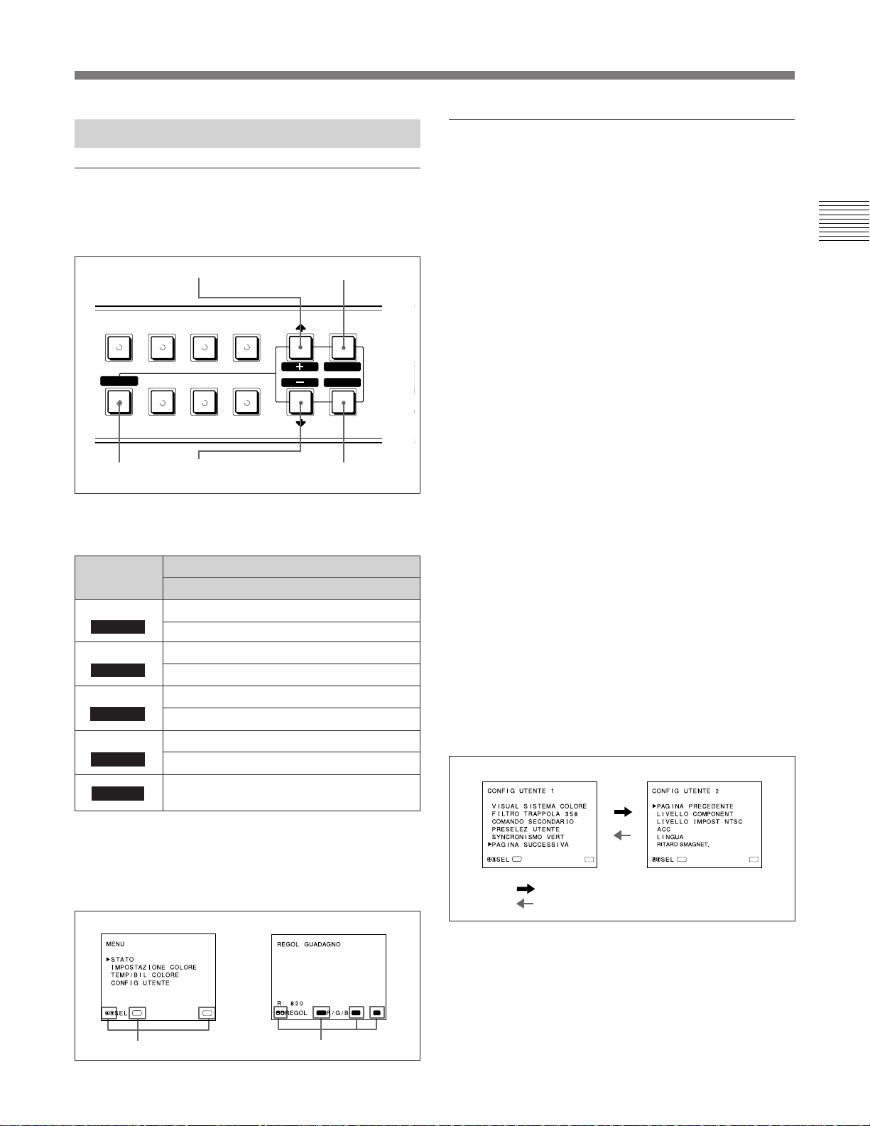
Operazioni tramite i menu a schermo
T
/
M
Procedimenti operativi
Tasti per l’utilizzo dei menu
Sul pannello anteriore del monitor sono collocati
cinque tasti per l’utilizzo dei menu.
3Tasto >/+
B/
COMPONENT
B
RESET
BLUE
ONLY
5Tasto RESET
C/
SDI
UNDER
SCAN
LINE/
DELAY
4Tasto ./–
RGB
H/V
EXT
SYNC
16:9
La tabella seguente mostra come funzionano questi
cinque tasti quando si utilizzano i menu.
Tasto
MENU
1
EXIT
ENTER
2
SELECT
>
3
+
.
4
–
5 RESET
Per selezionare un’opzione del menu
Per regolare la voce selezionata
ritorna al menu precedente
ritorna al menu precedente
seleziona un’opzione
conferma l’opzione selezionata
sposta il cursore (z) verso l’alto
fa aumentare il valore selezionato
tosposta il cursore (z) verso il basso
fa diminuire il valore seleziona
ripristina l’opzione corrente al valore
standard predefinito
1Tasto
MENU/EXIT
MENU
EXIT
SELECT
ENTER
2Tasto ENTER/
SELECT
APER
MIN
Per visualizzare il menu, seguire i passi illustrati sotto.
1 Premere il tasto MENU/EXIT (1).
Appare 1 MENU (menu principale).
2 Spostare il cursore (z) sul menu di impostazione
desiderato desiderata premendo il tasto ./– o >/+
(4, 3).
3 Premere il tasto ENTER/SELECT (2).
Appare il menu di impostazione selezionato al
passo 2.
4 Spostare il cursore (z) sulla voce desiderata
premendo il tasto ./– o >/+ (4, 3).
5 Premere il tasto ENTER/SELECT (2).
Appare lo schermo di regolazione o il menu di
impostazione selezionato al passo 4.
Per istruzioni più dettagliate sui menu, vedere la sezione
“Funzioni dei menu a schermo” a pag. 10(I).
Per visualizzare la pagina successiva o
precedente del menu
Selezionare PAGINA SUCCESSIVA nel menu per
visualizzare la pagina successiva e PAGINA
PRECEDENTE per visualizzare la pagina precedente.
MENU 1
MENU 2
I tasti che possono essere utilizzati sul menu e sugli
schermi di regolazione vengono visualizzati in basso
ENTER
MENU
ENTER
MENU
allo schermo. È possibile effettuare operazioni sui
:
menu utilizzando i tasti visualizzati.
Menu Impostazione
ENTER
MENU
Schermo di regolazione
SELECT
RESET
EXIT
Come visualizzare la pagina precedente o successiva
Per chiudere il menu per ritornare allo
schermo normale
Ogni volta che si preme il tasto MENU/EXIT (1), il
PAGINA SUCCESSIVA
PAGINA PRECEDENTE
:
menu a schermo ritorna a quello precedentemente
Tasti utilizzabili
Tasti utilizzabili
Tasti utilizzabili del menu
visualizzato. Premere il tasto MENU/EXIT (1)
ripetutamente finché non appare lo schermo normale.
9(I)
Page 30
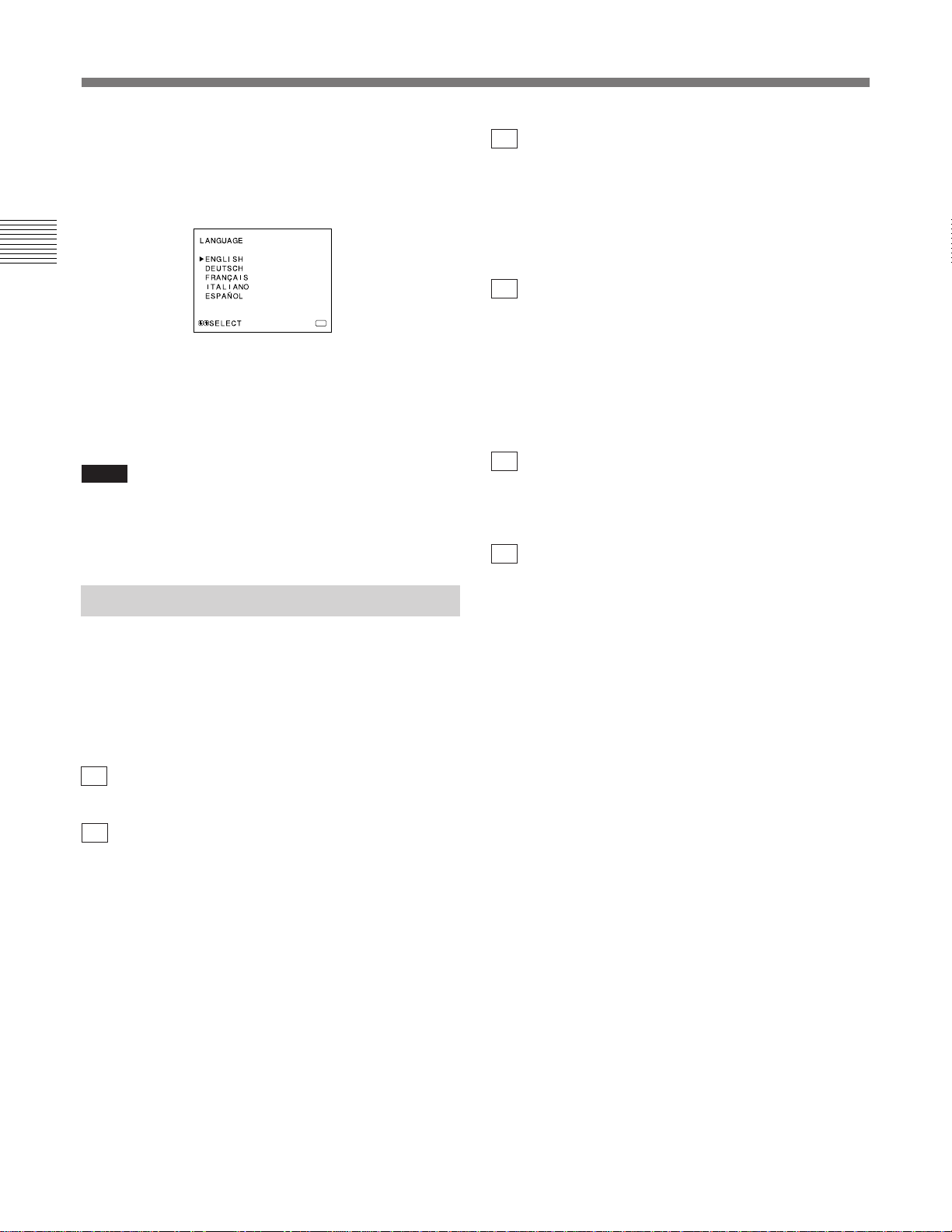
Uso dei menu a schermo
Per selezionare la lingua
Quando si accende il monitor per la prima volta, viene
visualizzato il menu LANGUAGE (@£). Selezionare la
lingua desiderata.
MENU
1 Spostare il cursore (z) sulla lingua desiderata
premendo il tasto ./– o >/+ (4, 3).
2 Premere il tasto MENU/EXIT (1).
Nota
Se non si preme il tasto MENU/EXIT (1) nella
procedura descritta sopra , il menu LANGUAGE
apparirà sempre quando si accende il monitor.
Funzioni dei menu a schermo
5a Menu AUDIO SDI (quando BKM-101C è
installato per il modello BVM-20M4E/14M4E)
Quando non viene selezionato il suono (NONE) o il
suono analogico tramite la presa AUDIO IN nei
connettori analogici RGB (ANALOG (RGB)).
I segnali digitali del suono non vengono selezionati.
[NONE]
5b Menu AUDIO SDI (quando BKM-102 è
installato per il modello BVM-20M4DE/
20M4E/14M4DE/14M4E)
Selezionare i canali di uscita dei segnali del suono
digitale o il suono analogico tramite la presa AUDIO
IN nei connettori RGB analogici. Quando si seleziona
“CH1+CH2”, è possibile controllare il suono dai canali
1 e 2. [CH1+CH2]
6a Menu CONFIG UTENTE 1
Selezionare una voce da regolare sui menu e gli schermi
(!™ attraverso !ª). Per passare al menu CONFIG
UTENTE 2, selezionare PAGINA SUCCESSIVA.
6b Menu CONFIG UTENTE 2
Selezionare una voce da regolare sui menu e gli schermi
(@º attraverso @∞). Per passare al menu CONFIG
UTENTE 1 selezionare PAGINA PRECEDENTE.
Le parentesi quadre [ ] contengono il valore standard
predefinito.
1Menu principale
Selezionare un altro menu e premere ENTER/SELECT
per passare al sottomenu.
2a Menu STATO 1
Mostra le impostazioni correnti.
2b Menu STATO 2
Mostra il kit in opzione installato nel monitor.
3Menu IMPOSTAZIONE COLORE
Selezionare SI sul menu per attivare le regolazioni
CHROMA e PHASE (solo NTSC) effettuate sul
videata REGOLAZIONE AUTOMATICA (7). [NO]
4Menu TEMP/BIL COLORE
Selezionare la temperatura del colore tra D65, D93 e
UTENTE. L’opzione UTENTE è preimpostata su D65.
La temperatura del colore può essere regolata o
modificata in modalità UTENTE (è necessario uno
strumento di misura). [D65]
7Videata REGOLAZIONE AUTOMATICA
Selezionare il segnale a barra del colore (pieno,
SMPTE, EIA) e premere ENTER/SELECT per avviare
automaticamente le regolazioni CHROMA e PHASE
(solo NTSC).
Per attivare queste regolazioni, selezionare SI sul menu
IMPOSTAZIONE COLORE (3).
8Videata REGOL GUADAGNO
Regolare l’opzione GUADAGNO in modalità
UTENTE.
9Videata REGOL BIAS
Regolare l’opzione BIAS in modalità UTENTE.
!ºMenu GAMMA TEMP COLORE
Selezionare la gamma di temperatura del colore in
modalità UTENTE. [5000K – 10000K]
!¡Menu COPIA UTENTE
Memorizzare le impostazioni di fabbrica di D65 o D93
come valore per il modo UTENTE.
10(I)
Page 31

!™Menu VISUAL SISTEMA COLORE
Selezionare il periodo di visualizzazione del sistema
del colore dei segnali di ingresso correnti.
Quando è selezionato AUTO, il sistema di colore in
uso appare sullo schermo ogni volta che il segnale di
ingresso viene modificato. [AUTO]
!£Menu FILTRO TRAPPOLA 358
Selezionando SI è possibile eliminare le sbavature o i
disturbi del colore (solo NTSC). [NO]
Normalmente selezionare NO.
!¢ Menu COMANDO SECONDARIO
Selezionare una voce (comandi CONTRAST,
BRIGHT, CHROMA e PHASE sul pannello anteriore)
per la regolazione fine sullo schermo COMANDO
SECONDARIO (!∞).
!∞Videata COMANDO SECONDARIO
Eseguire la regolazione fine della voce selezionata nel
menu COMANDO SECONDARIO (!¢). Ogni
comando (CONTRAST, BRIGHT, CHROMA e
PHASE) possiede una posizione a scatto al centro del
proprio intervallo di regolazione. Con questa funzione
è possibile impostare il valore di regolazione della
posizione di scatto.
!§Menu PRESELEZ UTENTE
Se si preme SI su questo menu, l’indicatore REMOTE
si accende e i comandi del pannello anteriore
vengonodisabilitati. Il monitor funziona con le
impostazioni preimpostate.
Per regolare le impostazioni definite dall’utente,
selezionare il menu PRESELEZ REGOL (!¶). [NO]
!¶Menu PRESELEZ REGOL
È possibile preimpostare i comandi BRIGHT,
CHROMA, PHASE, CONTRAST, VOLUME e
APERTURE al livello desiderato e utilizzare queste
impostazioni per selezionare SI sul menu PRESELEZ
UTENTE (!§).
!•Videata PRESELEZ REGOL
Regolare la voce selezionata (BRIGHT, CHROMA,
PHASE, CONTRAST, VOLUME e APERTURE) nel
menu PRESELEZ REGOL (!¶).
!ªVideata SINCRONISMO VERT
Se l’immagine scorre verticalmente sullo schermo,
regolare il sincronismo verticale.
Nota
Se non si riescono a leggere le scritte visualizzate sul
display, selezionare l’ingresso che non è collegato.
@ºMenu LIVELLO COMPONENT
Selezionare il livello componente tra le tre modalità
disponibili.
N10/SMPTE per segnali 100/0/100/0
BETA 7.5 per segnali 100/7,5/75/7,5
BETA 0 per segnali 100/0/75/0
[N10/SMPTE]
@¡Menu LIVELLO IMPOST NTSC
Selezionare il livello di impostazione NTSC tra le due
opzioni disponibili. Il livello 7,5 viene usato
principalmente in Nordamerica. Il livello 0 viene usato
principalmente in Europa. [0]
@™Menu ACC
Consente di attivare o disattivare il circuito ACC
(Auto Color Control). Quando è necessaria la
regolazione fine, selezionare NO sul menu ACC.
Normalmente seØUzionare SI. [SI]
@£Menu LINGUA
È possibile selezionare dal menu una delle cinque
lingue disponibili (inglese, tedesco, francese, italiano,
spagnolo). [ENGLISH]
@¢Menu RITARDO SMAGNET.
Impostare l’ora affinché la funzione della
smagnetizzazione funzioni dopo che viene attivata
l’alimentazione.
Questa funzione può essere impostata da 0 a 99
secondi. [0]
Solo per il modello BVM-20M4DE/20M4E
@∞Videata ATTERRAGGIO
Se il colore non è uniforme anche dopo aver premuto il
tast DEGAUSS, è possibile regolare l'atterraggio per
ottenere un colore uniforme su questo schermo.
Per regolare l'atterraggio sono disponibili i due metodi
seguenti.
Quando i segnali delle righe orizzontali
vengono ricevute e visualizzate:
Premere il tasto ./– o >/+ fino a visualizzare le righe
sullo schermo il più orizzontalmente possibile.
Quando i segnali del colore bianco vengono
ricevuti e visualizzati:
Premere il tasto ./– o >/+ finché il colore bianco a
schermo non diventa il più uniforme possibile.
Per ripristinare le impostazioni standard (00),
premere il tasti ./– e >/+.
11(I)
Page 32
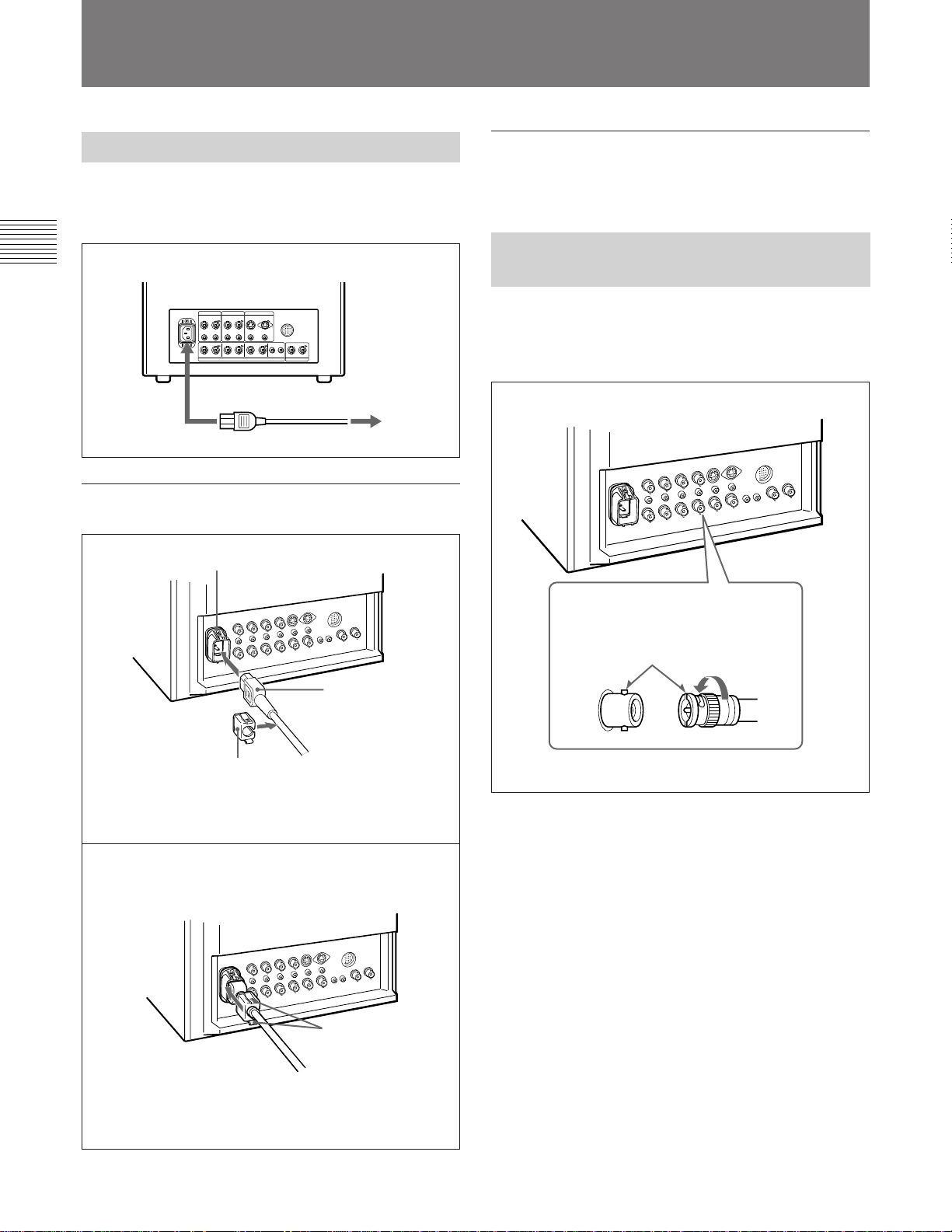
Collegamenti
Collegamento del cavo di alimentazione CA
Collegare il cavo di alimentazione (in dotazione) alla
presa AC IN e ad una presa di rete.
AC IN alla presa di rete
Per rimuovere il cavo di alimentazione CA
Estrarre il fermaspina mentre si premono le levette di
bloccaggio.
Collegare un cavo coassiale con prese BNC ai
connettori BNC sul pannelo posteriore come illustrato
sotto.
Per collegare saldamente un cavo di
alimentazione ad un fermaspina
1
Presa AC IN
Collegamento di un cavo ad un connettore BNC
Spina di alimentazione
Fermaspina
Inserire il cavo di alimentazione nella presa AC IN.
Applicare quindi il fermaspina (in dotazione) sopra il
cavo di alimentazione.
2
Levette di bloccaggio
Inserire la presa BNC nel connettore
del pannello anteriore, facendo
corrispondere le fessure e i piedini e
girare la presa BNC in senso orario
per assicurare il collegamento.
Far scorrere il fermaspina lungo il cavo finché non si
blocca.
12(I)
Page 33

Caratteristiche tecniche
Segnale video
Sistema del colore PAL, NTSC, SECAM, NTSC4,43
Risoluzione 800 righe TV
Correzione dell’apertura
da 0 dB a 6 dB
Risposta di frequenza
LINE 10 MHz ± 3 dB (segnale Y)
RGB 10 MHz ± 3 dB
Sincronizzazione Durata AFC costante 1 msec
Caratteristiche dell’immagine
Scansione normale Sovrascansione del 2 % dell’area dello
schermo a raggi catodici effettiva
Luminanza preimpostata 90 cd/m2
BRIGHT e CONTRAST sono impostati
sulla posizione di click centrale)
Sottoscansione Sottoscansione del 5 % dell’area dello
schermo a raggi catodici effettiva
Linearità orizzontale BVM-20M4DE/20M4E:
Meno del 5,0% (tipica)
BVM-14M4DE/14M4E:
Meno del 4,0% (tipica)
Linearità verticale BVM-20M4DE/20M4E:
Meno del 5,0% (tipica)
BVM-14M4DE/14M4E:
Meno del 4,0% (tipica)
Convergenza
Area centrale: BVM-20M4DE/20M4E:
Meno del 0,5 mm (tipica)
BVM-14M4DE/14M4E:
Meno del 0,4 mm (tipica)
Area periferica: BVM-20M4DE/20M4E:
Meno del 0,7 mm (tipica)
BVM-14M4DE/14M4E:
Meno del 0,5 mm (tipica)
Stabilità del percorso di scansione
Orizzontale 1,0%, Verticale 1,5%
Regolazione dell’alto voltaggio
BVM-20M4DE/20M4E: 4,0%
BVM-14M4DE/14M4E: 3,5%
Temperatura del colore
D65/D93, UTENTE selezionabile
(3.200K–10.000K, l’impostazione in
fabbrica è D65)
(Quando i comandi
Ingressi
LINE A/B
VIDEO IN Connettore (×2), 1Vp-p ±6 dB,
sinc negativa
AUDIO IN Presa fono (×2), –5 dBu a) più di 47
kilohm
.................................................................................................................................................................................................................................
1) 0 dBu = 0,775 Vr.m.s.
LINE C
Y/C IN Mini DIN a 4 piedini (×1)
Vedere la sezione sull’assegnazione
dei piedini alla pagina 14(I).
AUDIO IN Presa fono (×1), –5 dBu1), più di 47
kilohm
RGB/COMPONENT
R/R-Y, G/Y, B/B-Y IN: Connettore BNC (×3)
Canali R, G, B: 0,7 Vp-p, ±6 dB
Sincronizzazione su verde:
0,3 Vp-p, negativa
Canale R-Y, B-Y: 0,7 Vp-p, ±6 dB
Canale Y: 0,7 Vp-p, ±6 dB
del colore standard a crominanza del 75%)
AUDIO IN Presa fono (×1), –5 dBua), più di 47
kilohm
EXT SYNC IN Connettore BNC (×1)
4 Vp-p, ±6 dB, sinc negativa
COMPONENT SDI IN (solo per il modello BVM-20M4DE/
14M4DE)
Connettore BNC (x1)
Digitale seriale (270M bit/s)
SMPTE 259M/CCIR 656-III
Quantizzazione: 10 bit/campione
Risposta di frequenza:
Y: 5.75 MHz, –3 dB
R-Y/B-Y: 2.75 MHz, –3 dB
REMOTE Connettore a 20 piedini (×1)
Vedere la sezione sull’assegnazione
dei piedini alla pagina 14(I).
(segnale della barra
Uscite
LINE A/B
VIDEO OUT Connettore BNC (×2), a circuito aperto
Terminazione a 75 ohm automatica
AUDIO OUTPresa fono (×2), a circuito aperto
LINE C
Y/C OUT
AUDIO OUTPresa fono (×1), a circuito aperto
RGB/COMPONENT
R/R-Y, G/Y, B/B-Y OUT: Connettore BNC (×3) a
AUDIO OUTPresa fono (×1), a circuito aperto
EXT SYNC OUT Connettore BNC (×1)
COMPONENT SDI OUT (solo per il modello BVM-
Uscita del diffusore Livello di uscita: 0,8 W
Mini DIN a 4 piedini (×1), a circuito aperto
Terminazione a 75 ohm automatica
circuito aperto
Terminazione a 75 ohm automatica
Terminazione a 75 ohm automatica
20M4DE/14M4DE)
Connettore BNC (x1)
Uscita ciclo attivo
Digitale seriale (270M bit/s)
SMPTE 259M/CCIR 656-III
13(I)
Page 34
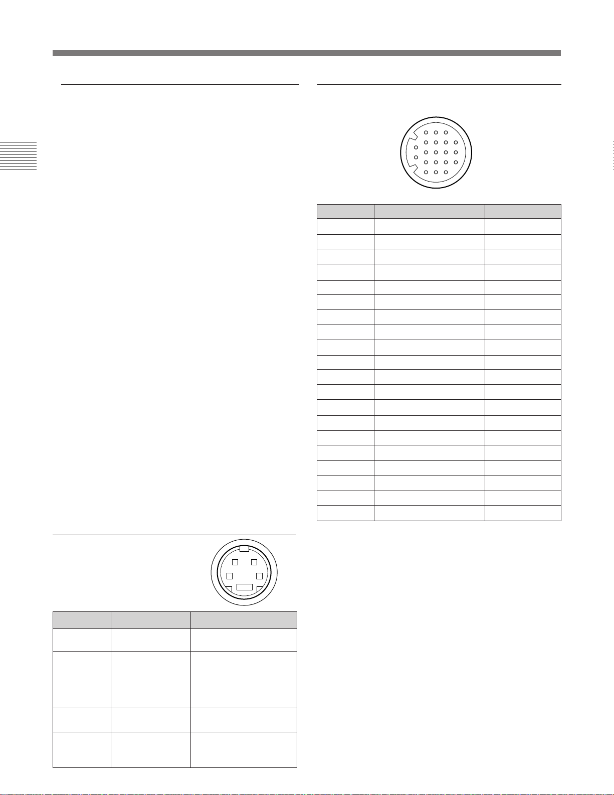
Caratteristiche tecniche
Informazioni generali
Raggi catodici Fosforo EBU
Consumo energetico
BVM-20M4DE/20M4E: 140 W
BVM-14M4DE/14M4E: 99 W
Alimentazione CA da 100 a 240 V, 50/60 Hz
Corrente di punta di entrata
BVM-20M4DE/20M4E:
(1) Stato di accensione (ON), metodo di
sondaggio di corrente: 18 A (240 V)
(2) Corrente di entrata a commutazione a
caldo, misurata secondo la normativa
europea EN55103-1: 7 A (230 V)
BVM-14M4DE/14M4E:
(1) Stato di accensione (ON), metodo di
sondaggio di corrente: 18 A (240 V)
(2) Corrente di entrata a commutazione a
caldo, misurata secondo la normativa
europea EN55103-1: 4 A (230 V)
Temperatura di utilizzo
da 0 a 35° C
Umidità durante l’utilizzo
da 0 a 90 % (senza condensa)
Dimensioni (l/a/p)
BVM-20M4DE/20M4E:
Circa 450 × 458 × 503 mm
BVM-14M4DE/14M4E:
Circa 346 × 340 × 431 mm
escluse le parti sporgenti e i comandi
Peso BVM-20M4DE/20M4E: Circa 31 Kg
BVM-14M4DE/14M4E: Circa 18 Kg
Accessori in dotazione
Cavo di alimentazione CA (1),
Fermaspina CA (1), Etichetta di controllo
(1), Cavo con connettore a 20 piedini (1),
Manuale per il funzionamento (1)
Il design e le caratteristiche tecniche sono soggetti a
modifiche senza preavviso.
Connettore REMOTE (20 piedini)
3
8
13
4
9
14
18
5
10
15
19
6
11
16
20
7
12
17
Colore del cavo
Marrone
Rosso
Arancio
Giallo
Verde
Blu
Viola
Grigio
Bianco
Nero
Rosa
Azzurro
Spirale arancio
Spirale gialla
Spirale verde
Spirale blu
Spirale viola
Spirale grigia
Spirale rosa
Spirale azzurra
Piedino N.
1
2
3
4
5
6
7
8
9
10
11
12
13
14
15
16
17
18
19
20
1
2
Segnale
Solo blu
H/V DELAY
MAIN/SUB*
EXT SYNC
DEGAUSS
R ch ON/OFF*
TALLY
LINE B
GND
GND
GND
GND
LINE A
LINE/RGB
GND
L ch ON/OFF*
REMOTE
LINE C
UNDER SCAN
16:9
Assegnazione dei piedini
Connettore Y/C IN
(mini DIN a 4 piedini)
Piedino N.
1
2
3
4
Segnale
Ingresso Y
Ingresso
sottoportante
COLORE
TERRA per
ingresso Y
TERRA per
ingresso
COLORE
14(I)
21
34
*
Descrizione
1 Vp-p, sincr. negativa,
75 ohm
300 mVp-p (PAL), 286
mVp-p (NTSC), burst
Ritardo fra Y e C:
compreso fra 0 ± 100
nsec., 75 ohm
TERRA
TERRA
(* Per il controllo audio digitale)
Come effettuare un collegamento con un
apparecchio di controllo remoto
Collegare il piedino N. 17 ad uno dei piedini GND (N.
9 –12 e 15 ) quindi collegare i piedini per le funzioni
che si desidera utilizzare agli altri piedini GND (N.9–
12 e 15).
Come accendere la spida di controllo
Collegare il piedinoN. 7 ad uno dei piedini GND (N. 9
–12 e 15 ).
Page 35

The material contained in this manual consists of information
that is the property of Sony Corporation and is intended
solely for use by the purchasers of the equipment described
in this manual.
Sony Corporation expressly prohibits the duplication of any
portion of this manual or the use thereof for any purpose
other than the operation or maintenance of the equipment
described in this manual without the express written
permission of Sony Corporation.
Le informazioni contenute in questo manuale sono di
proprietà della Sony Corporation e sono indirizzate
solamente agli acquirenti dell’apparecchio descritto in questo
manuale.
Sony Corporation non ammette esplicitamente la copia di
nessuna parte del manuale o un uso per quanto riguarda il
funzionamento o la manutenzione diverso da quello descritto
nello stesso manuale senza il permesso scritto della Sony
Corporation.
Page 36

BVM-20M4DE
BVM-20M4E
BVM-14M4DE
BVM-14M4E
3-861-850-12 (1)
Sony Corporation
Communication System Solutions Network Company
Printed in Japan
2000. 08. 08
©1997
 Loading...