

Sony TCS-100DV Service manual
TCS-100DV
SERVICE MANUAL
Ver 1.0 2000. 02
SPECIFICATIONS
Recording system
4-track 2-channel stereo
Tape speed
4.8 cm/s or 2.4 cm/s
Frequency range
150 – 8,000 Hz using normal (TYPE I) cassette (with REC TIME switch at “NORMAL”)
Speaker
Approx. 3.6 cm (1 ⁄ in.) dia.
Power output
Speaker:70 mW (at 10% harmonic distortion)
Head phones:3 mW + 3 mW (at 10% harmonic distortion)
Input
Microphone input jack (minijack) sensitivity 0.4 mV for 3 kilohms or lower
impedance microphone
Output
i (headphones) jack (minijack) for 8 – 300 ohms headphones
Variable range of the speed control
From +20% to –15% (with REC/TIME switch at “NORMAL”)
Power requirements
1.5V DC batteries size AAA (R03) × 2/External DC 1.5V power souces
Dimensions (w/h/d) incl. projecting parts and controls
Approx. 112 × 30 × 78 mm (4 ⁄ × 1 ⁄ × 3 ⁄ in.)
Mass
Approx. 190 g (6.8 oz)
Supplied accessories
Carrying pouch (1)
Sony manganese batteries R03 (SB) (2) (Sony world model only)
Headphones with remote control (1)
Hand strap (1)
Design and specifications are subject to change without notice.
7
16
343161
US Model
AEP Model
Tourist Model
Model Name Using Similar Mechanism NEW
T ape Transport Mechanism Type MT-TCS100-162
8
STEREO CASSETTE-CORDER

TABLE OF CONTENTS
1. SERVICING NOTES............................................... 3
2. GENERAL ................................................................... 5
3. DISASSEMBLY ......................................................... 6
4. MECHANICAL ADJUSTMENT.......................... 11
5. ELECTRICAL ADJUSTMENT............................ 11
6. DIAGRAMS
6-1. Block Diagram – AUDIO Section – .............................. 13
6-2. Block Diagram – MAIN Section – ................................ 15
6-3. Printed Wiring Boards..................................................... 18
6-4. Schematic Diagram ......................................................... 21
6-5. IC Pin Function Description ........................................... 28
7. EXPLODED VIEWS................................................ 30
8. ELECTRICAL PARTS LIST ............................... 33
Flexible Circuit Board Repairing
• Keep the temperature of the soldering iron around 270 ˚C during repairing.
• Do not touch the soldering iron on the same conductor of the
circuit board (within 3 times).
• Be careful not to apply force on the conductor when soldering
or unsoldering.
Notes on chip component replacement
• Never reuse a disconnected chip component.
• Notice that the minus side of a tantalum capacitor may be damaged by heat.
– 2 –
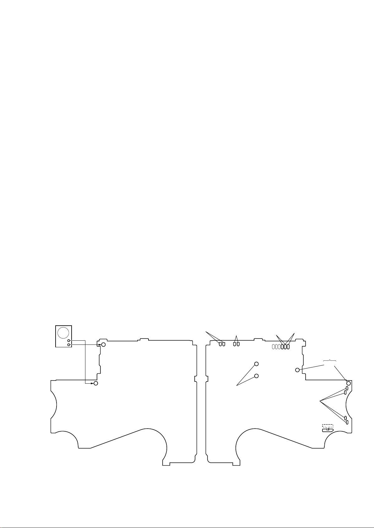
SECTION 1
REC PROTECT
DETECT (REV )
switch
S702-1
– MAIN BOARD (Component Side) –
TAPE DETECT
switch
S702-2
AT S
switch
S703-2
REC PROTECT
DETECT (FWD)
switch
S703-1
connect to
plunger (PM701)
connect to
motor (M601)
DIRECTION
FWD ←STOP→ REV
battery terminal
#3
TP40 (GND)
TP33 (PHOTO IN)
AF oscillator
square wave
(sine wave)
10 Hz,–3.5 dB
– MAIN BOARD (Conductor Side) –
S701
+
–
SERVICING NOTES
SERVICE MODE
This set detects the rotation of the idler gear (A) (side S) using the
photo reflector (PH701). The PH701 is mounted on the MAIN
board, therefore the idler gear (A) (side S) cannot be detected with
the MAIN board removed. As a result, the motor (M601) cannot
be controlled, causing malfunction.
Further, the DIRECTION switch (S701) is also mounted on the
MAIN board, and with the board removed, the mechanism position cannot be detected and the operation is not changed over.
Therefor, when the voltage check is e xecuted with the MAIN board
removed, follow the procedure provided below.
1. Setting
1) Refer to “3. DISASSEMBLY”, and remove the MAIN board.
2) Connect the MAIN board to the motor (M601) and the plunger
(PM701) using jumper wires. These can be connected easily
with the use of the extension tool (Part No. 1-769-143-11) (ten
in one set).
3) Short each terminals of REC PROTECT DETECT (REV)
switch (S702-1), T APE DETECT switch (S702-2), REC PR OTECT (FWD) switch (S703-1) and ATS switch (S703-2).
4) Connect the AF oscillator to the TP33 (PHOTO IN) and the
TP40 (GND).
5) Supply 1.3 V to the battery terminals using the regulated po wer
supply.
2. Preset state
T o set the REC, PLAY, FF, REW modes, the preset state must
be set.
1) Check that the slider (NR) and the DIRECTION switch (S701)
are set to the center position. If not, set the preset state as follow.
2) Move the DIRECTION switch (S701) to the side, which the
slider (NR) is facing.
3) The slider (NR) will move when the regulated power supply
switch is set to OFF once and then set to ON. Move the DIRECTION switch (S701) according to this timing and set to
the center position.
3. FF, REW modes
1) Check that the preset state is set.
2) Input the square wave or sine wave to the TP33 (PHOTO IN)
and the TP40 (GND).
3) Press the [FF/CUE ] button (S4)
or the [REW/REVIEW ] button (S5).
M
m
4. REC, PLAY modes
1) Check that the preset state is set.
2) Input the square wave or sine wave to the TP33 (PHOTO IN)
and the TP40 (GND).
3) Press the [REC] switch (S6) or [PLAY/DIR ] botton (S3)
Y
will move the slider (NR) once towards the side R and then to
the side F . Move the DIRECTION s witch (S701) according to
this timing will set the REC or PLAY mode (side F). Press the
[REC] switch (S6) or [PLAY/DIR ] botton (S3) another
Y
time and move the DIRECTION switch (S701) according to
the movement of the slider (NR) will set the REC or PLAY
mode (side R).
Note 1: If the above fails, perform from preset again.
Note 2: Use each button on the r emote controller as much as possible. If
Note 3: When using headphones, the timing for move the DIRECTION
no remote controller, do not touch the buttons with your hands,
but using a stick with a round tip.
switch (S701) can be determined from the beep sound.
– 3 –
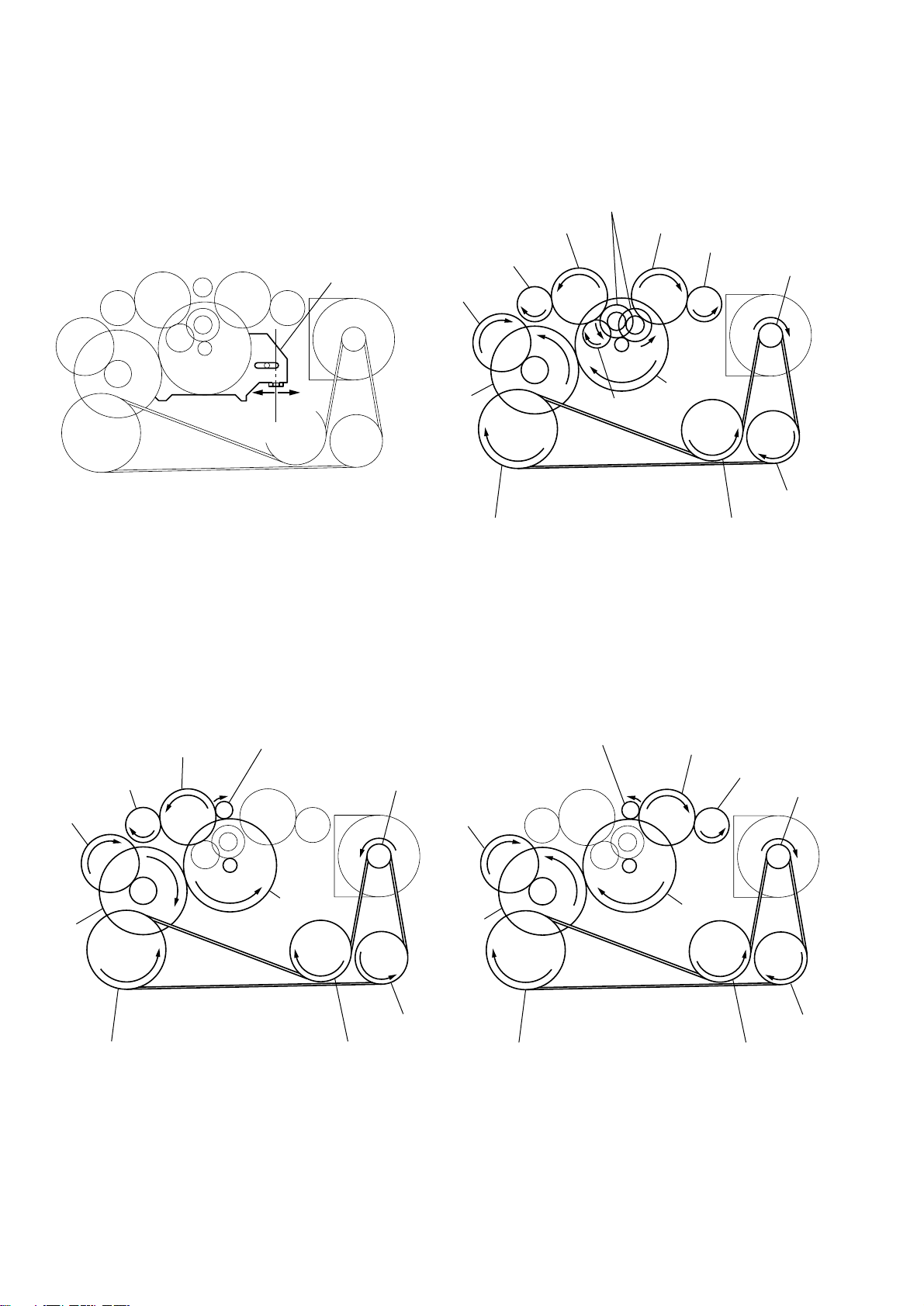
Slider (NR) Rotation system
y
y
y
Rotation system during PLAY.
idler gear (A) (side T)
gear (REEL) (side T)
slider (NR)
cam gear
gear (NR)
(FWD : left side/
REV : right side)
idler gear (A) (side S)
gear (REEL) (side S)
motor pulley
side F
side R
center
gear (Y)
insert flywheel (N) insert flywheel (R)
idler gear (B)
Rotation system during FF. Rotation system during REW.
gear (FR)
(REW: right side)
idler gear (A) (side T)
gear (REEL) (side T)
cam gear
gear (FR)
(FF: left side)
motor pulley
cam gear
clutch assy (F)
idler gear (A)
(side S)
reverse pulle
gear (REEL)
(side S)
motor pulle
clutch assy (F)
gear (Y)
insert flywheel (N) insert flywheel (R)
reverse pulle
– 4 –
gear (Y)
insert flywheel (N) insert flywheel (R)
clutch assy (F)
reverse pulley
SECTION 2
AA
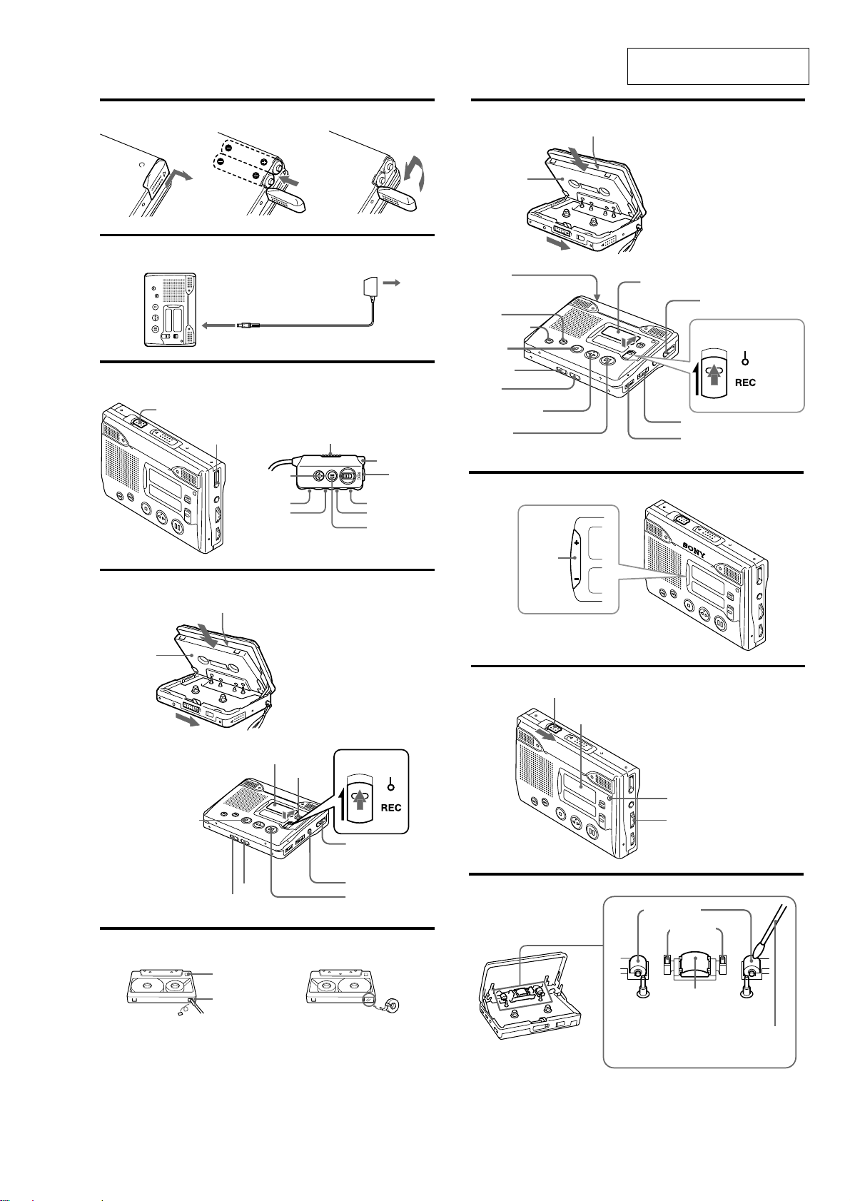
GENERAL
This section is extracted from
instruction manual.
A
B
C
HOLD
DC IN 1.5V
Remote Control
Controlador remoto
i/remote
i/Controlador remoto
n N PLAY
VOL
REW
AC power adaptor
Adaptador de alimentación
de CA
HOLD
i
V-UP
x STOP
FF
X PAUSE
F
Reverse side
of the tape
Cara posterior
del casete
HOLD
FF/CUE
REW/REVIEW
x STOP
MIC SENS
VOR
nN PLAY/DIR
X PAUSE
G
Upper side of the tape
Cara superior del casete
Display window
Visualizador
i/remote
i/Controlador remoto
SPEED CONTROL
VOL
REC indicator
Indicador REC
D
Reverse side
of the tape
Cara posterior
del casete
E
Upper side of the tape
Cara superior del casete
x STOP
VOR
MIC SENS
Side A
Cara A
Tab for side A
Lengüeta para
Display window
Visualizador
REC TIME
REC indicator
Indicador REC
i/remote
i/Controlador
remoto
MIC
X PAUSE
H
I
EASY
SEARCH
HOLD
Display window
Visualizador
COUNTER RESET
SPEED CONTROL
Pinch-roller
Rodillo compresor
Erase head
Cabeza
borradora
Record/Playback
head
Cabeza grabadora/
reproductora
Cotton swab
Palillo con
cabeza de
algodón
– 5 –
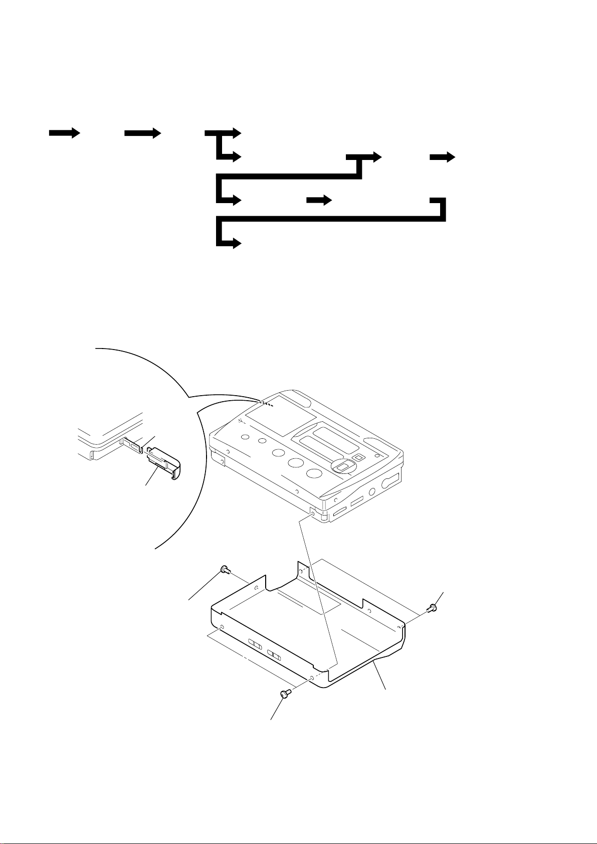
• This set can be disassembled in the order shown below.
)
SECTION 3
DISASSEMBLY
Set
Note: Follow the disassembly procedure in the numerical order given.
Case Assy
Lid Sub
Assy,
Cassette
Lid Assy, Cassette
Ornament Sub Assy, Reel
Holder (F) Assy
MAGNETIC HEAD (H901)
CASE ASSY
MAIN board
Pinch Lever (N)/(R) Assy
belt, motor (M601)
2 claw
1 Open the “lid, battery case”.
3 lid, battery case
4 screw
(M1.4 × 2.5)
4 two screws
5 case assy
(M1.4 × 2.5
4 two screws
(M1.4 × 2.5)
– 6 –
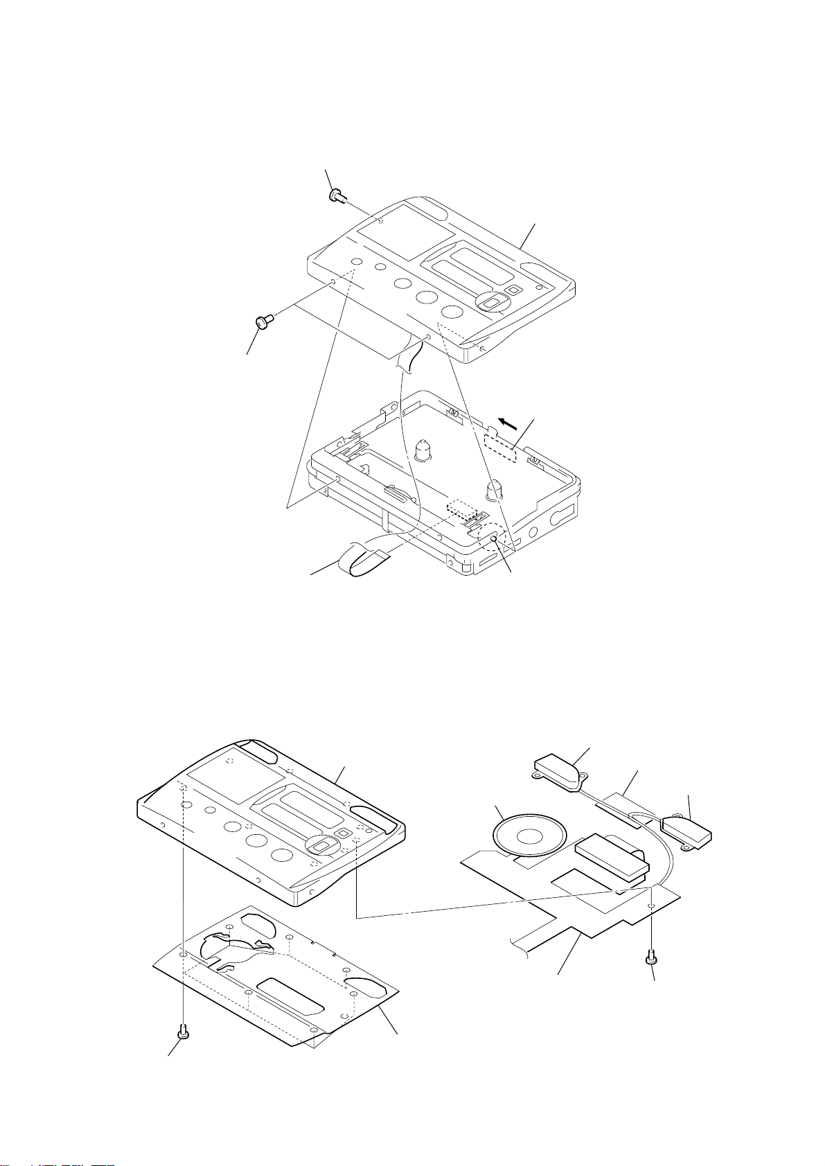
LID SUB ASSY, CASSETTE
)
2 screw
(M1.4 × 2)
2 screw (M1.4 × 2)
5 lid sub assy, cassette
3 knob (open)
LID ASSY, CASSETTE
1 key board unit
(CN 1)
6 lid assy, cassette
4 shaft
speaker (3.6 cm)
microphone sub assy (L)
4 cushion (B)
microphone sub assy (R
1 seven screws
2 cover
– 7 –
5 key board unit
3 screw
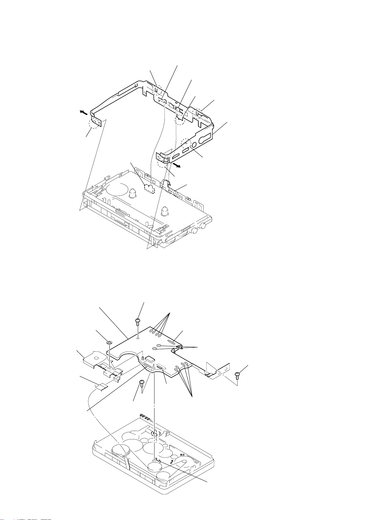
ORNAMENT SUB ASSY, REEL
1 claw
S704
4 claw
knob (hold)
knob (open)
1 claw
lever, lock
3 boss
2 claw
4 claw
5 ornament sub assy, reel
Note: On installation case assy
adjust the S704 and knob (hold),
“lever, lock” and knob (open).
MAIN BOARD
1 key board unit
(CN 1)
6 Remove five solders
of VOR flexible board.
0 MAIN board
7 washer
8 bracket (SW)
9 screw
8 screw
(M1.4)
(M1.4)
2 Remove four solders of leaf switch.
3 Remove six solders
of ATS flexible board.
4 Remove two solders
of plunger solenoid.
9 screw
S701
5 Remove four solders
of motor.
Note: On installation MAIN board
adjust the S701 and slider.
– 8 –
slider
 Loading...