

Sony TC-PB10 Service Manual

CASSETTE PLAYER
Playback
System:
Fast-forward
and
Rewind
Time:
Playback
Signal-to-
noise
Ratio:
SPECIFICATIONS
4-track
2-channel
stereo
Approx.
90
sec.
(with
C-60 cassette)
.With
TYPE lV
cassette
(Sony
METALLIC)
60 dB at
peak
level . . . US model
60 dB at
peak
level
(NAB)
I
60 dB
(DtN)
J
AtY' È' uK model
.With
TYPE lV
cassettF
(Sony
METALLIC)
20 - 18,000
Hz
30 - 16,000
Hz
(t
3 dB)
.With
TYPE
I
cassette
(Sony
HFX)
. . .
US
model
Power
Output:
US
model
12W
+
12 W
(70
Hz
-
20,O00 Hz,
1 % harmonic
distortion)
AEP, UK,
E model
25W+25W(Music)
50W+50W(peakmusic)
14W
+
14 W
(1
kHz,
1 % harmonic
distortion)
Harmonic
Distortion:
O.OSo/"
14
W
+
4 W)
lnputs;
Microphone
input
(phone
iack)
Sensitivity
O.435
mV
(-65
dB)
For
a low-impedance
microphone
AUX IN
Sensitivity
435
mV
(-S
dB)
Input
impedance
5
kf,ù
Outputs:
Line
outputs
Output
level
250 mV
(*10
dB)
at
toad
impedance
50 kf,ù
Load
impedance
over 1O k,fl
Headphone
output
Output level
380
mV
(-16
dB)
at a toad
impedance
of 8 f,l with
the volume
level
maximum
-
Continued
on
page
2
-
Frequency
Response:
(Sony
BHF)
. . .
AEP,
UK,
E model
20 - 1t,ooo Hz
30 - 15.000 Hz
(t
3
dB)
Wow
and
Flutter:
0.05 % WRMS . . .
US model
i3:.i#Hi,(NAB)
IAEP,
uK, E
model
Tape Transport Mechanism
Type
I
TCM-1 10V5
il====l
rrr
I
MICROFILM
I
SERIJICE
MANUAL
TC-PB I O
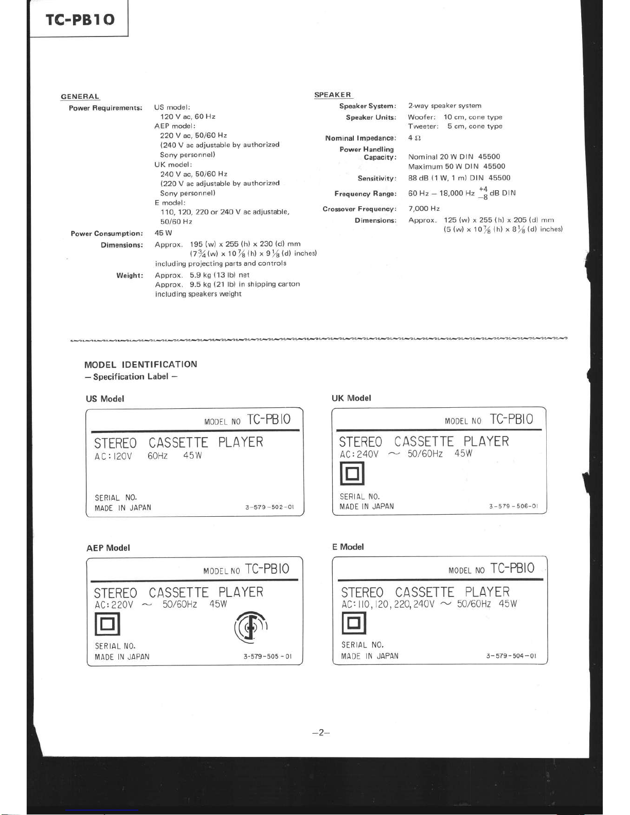
GENERAL
Power
Requirements:
Power Consumption:
Dimensions:
US model:
12OV
ac,60Hz
AEP model:
22OV
ac,50/60
Hz
(24OV
ac adjustable
by
authorized
Sony
personnel)
UK model:
24OY
ac,50/60
Hz
(22OV
ac adiustable
by authorized
Sony
personnel)
E
model:
110,12O,22O or
24O V ac adjustable,
50/60
Hz
45W
Approx.
195
(w)
x
255
(h)
x
230
(d)
mm
07afu1
x1o78hl
x9%(d) inches)
including
proiecting
parts
and controls
Approx.
5.9
kg
(13lb)
net
Approx. 9.5
kg
(21
lb) in shipping
carton
including speakers
weight
SPEAKER
Speaker
System:
Speaker
Units:
Nominal lmpedance:
Power Handling
Capacity:
Sensitivity:
Frequency Range:
Crossover
Frequency:
Dimensions:
2-way speaker system
Woofer:
1O cm,
cone
type
Tweeter: 5 cm, cone type
4{t
Nominal 20 W
DIN 45500
Maximum 50
W DIN 45500
88 dB
(1
W, 1 m)
DIN 45500
+^
60
Hz
-
'l
8,000
Hz
d
dB
DIN
7,OO0
Hz
Approx. 125
(w)
x 255
(h)
x 2O5
(d)
mm
(5 (w)
x 1o/8
lhl
x I
%
(d)
inches)
Weight:
MODEL
IDENTIFICATION
-
Specification
Label
-
666ûâ
US
Model
MODEL
NO
TC-PBIO
STEREO
CASSETTE
PLAYER
AC
r
l20V
60Hz
45W
SERIAL
NO.
MADE
lN JAPAN
3-57e-5o2-or
UK
Model
MODEL NO TC-PBIO
STEREO
CASSETTE
PLAYER
AC:
240V
-
50/60H2
45W
t:l
SERIAL NO.
MADE lN JAPAN
3-s7s-506-ol
AEP
Model
MODEL NO
TC-PBIO
STEREO
CASSETTE
PLAYER
ACt220V
50/60H2
45W
@'
SERIAL
NO.
MADE
IN JAPAN
3-579-505
-
0l
E Model
MODEL NO
TC-PBIO
STEREO CASSETTE
PLAYER
AC: Il0,
120,220,240V
-
50/60H2
45W
SERIAL
NO,
IVIADÊ
lN
JAPAN
3-5?e-504-ol

z
a
û!-0/
SECTION
1
OUTLINE
1.1. BLOCK
DIAGRAM
+t
@@
+++
@@æ
G.
Y
U
z
-
È
-o
o<
tsU
z
)
@
L
=
È
U
=
L
L
=
U
z
o
-
F
=
E
=
U
z
o
F
ô
z
U
J
o
É
3
æ
F
z
o
È
=
=
Y
=
ô
z
)
o
ù
=
É
U
=
æ
F
=
z
J
r
z
F
L
=
z
J
0
=
ox
==
o
=
r
no
51"
o
=
L
nÔ
uo
È
uo
=
o
É
o
F
-
bL"
b+;=
I
I
È
=
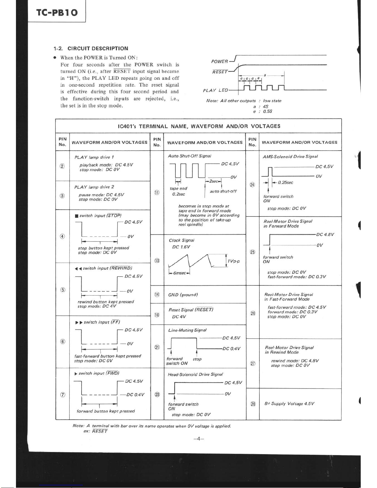
1-2.
CIRCUIT DESCRIPTION
o
When the
POWER
is Turned ON:
For
four
seconds after
the
POWER
switch is
turned ON
(i.e.,
after RESET input signal became
in
"H"),
the
PLAY LED repeats
going
on and
off
in one-second repetition rate.
The
reset signal
is effective during this
four second
period
and
the function-switch inputs are rejected,
i.e.,
the
set
is in the stop mode.
Note: All
other outputs
: low state
a:45
e : 0.55
1C401's TERMINAL NAME, WAVEFORM
AND/OR
VOLTAGES
PIN
No.
WAVEFORM
AND/OR
VOLTAGES
PIN
No.
WAVE
FORM AND/OR
VOLTAGES
PIN
No.
WAVEFORM
AND/OR
VOLTAGES
@
PLAY lamp
drive
1
playback
mode:
DC 4.5V
stop
mode: DC OV
@
Auto Shut-Off Signal
DC 4.5V
ts
tape end
O.2sec
OV
auto
shut-off
becomes in stop mode at
tape end in forward mode
(may
become in 0V according
to the
position
of
take-up
reel spindle)
@
AMS-S ol enoid
D rive S
ignal
rl
I
f
o.zssec
I
forward switch
ON
stop
mode:
DC OV
@
PLAY lamp
drive
2
pause
mode:
DC 4.5V
stop
mode: DC
OV
@
a
switch input
(STOP)
-l
7
DC
a.sv
tt
tl
L _____
'
_OV
F___r_D1
stop button
kept
pressed
stop
mode:
DC
0V
6À
R eel-M otor
D rive S ignal
in
Forward Mode
DC 4.8V
OV
forward switch
ON
stop
mode: DC
0V
fast-forward mode: DC
0.3V
@
Clock
Signal
DC't.6V
l*6msec-l
o
< <
switch input
(
R EWINDt
---.1
l-
DC 4.5V
tl
tl
i_______,_0V
r.-----Tr----
rewind button
kept
pressed
stop
mode: DC 4V
@
GND
(groundl
€e
R eel-M oto r D
rive
S ign al
in
Fast-Forward Mode
fast-forward mode: DC 4.5V
forward mode: DC
O.sV
stop
mode:
DC OV
@
Reset Signal
(RESET)
DC
4V
@
> >
switch input
(FF)
I 7
Dca.sv
tl
L- -----)-ov
@
Line-Muting
Signal
DC
O.4V
I
forward
switch
ON
I
stop
@
R eel-M
oto
r D rive
S ign al
in
Rewind Mode
rewind mode: DC 4.8V
stop mode:
DC
OV
@
forward
button
kept
pressed
>
switch input
IFWD)
f-
DC 4.5V
tl
tt
L------J
-Dco.4v
@
Head-Solenoid
Drive
Signal
DC
4.5V
OV
I
forward switch
ON
stop mode: DC 0V
@
B+ Supply Voltage
4.5V
Note: A
terminal
with bar
over
iB
name operates
when OV voltage
is
applied.
I
ex:
RESET
TC-PBI
O
I
-246-515-00
I
-210 -814-00
l
-210-815{0
1
-210-816-00
l
-210
-817-00
1
-210-818-00
I
-210-8r9{0
i
-210-820-00
I
-210-821
{0
t-244-?5440
I
-214-755
{0
I
-244-756-00
r-244-757
40
l
-244-758-00
r-214-75940
I
-214-760-00
t-214-76140
t-244-76240
l
-246-521
-00
t-246-52240
I
-246-523-00
t-216-52440
L-246-525{0
t-246-52640
t-246-52'l40
I
-246-528{0
l
-216-529{0
1
-246-530{0
I
-246-531
-00
1
-246-532-00
I
-246-533-00
I
-246-531
{0
l
-246-535-00
l
-246-536-00
I
-246-537
-00
1 246-538-00
I
-246
-539-00
I
-246-510{0
I
-216
-541
-00
r-246-51240
1
-246-543-00
1
-246-544{0
1.0M
1.lM
l.2M
l.6M
l.8M
2.7M
3.0M
3.3M
4.3M
4.7M
I
-216-49?
{0
l
-246-498-00
1-246-199{0
I
246-500-00
I
-246-501
{0
t-246-50240
I
-246-503-00
1
-246
-504-00
l
-246-505
{0
I
-246-506
-00
l
-246-507
{0
I
-246-508-00
1
-246-509-00
I
246
510{0
l 216-51r{0
t-246-512{0
1
-216-513-00
1
-246
-511-00
I
-246-51
5
-00
l
-246-516
{0
I
-246
-517
{0
I
-246-518
{0
t
-246-519-00
I
-246
-520-00
t00k
110k
l20k
130k
l50k
160k
180k
200k
220k
240k
270k
300k
330k
360k
390k
430k
470k
5l0k
560k
620k
680k
750k
820k
9l0k
|
-246-473-00
t-246-47
4-00
1-246-17540
t-246-476-00
t-246-477
-00
t-246-478-00
L-246-47940
1 246-480-00
l-246-481
00
r-246-482{0
I
-246-483-00
I
-246-484-00
I
-246-485-00
1
-246
-486-00
L-246-487
-00
I
-246-488-00
I
246
489-00
1
-246-190{0
1-246-491
00
t-246-492-00
I
-246
-493-00
1
-246-494
-00
I
-246-495{0
I
-246
-496-00
l0k
tlK
12k
l3k
IJK
l6k
18k
20k
22k
24k
27k
30k
33k
36k
39k
43k
47k
Jlk
56k
62k
68k
,JK
82k
91k
1 .0k
l.lk
l.2k
1 .3k
r .5k
I .6k
I .8k
2.0k
2.2k
2.4k
2.7k
3.0k
3.3k
3.6k
3.9k
4.3k
4.7k
5.
lk
5.6k
6.2k
6.8k
7 .5k
8. 2k
9. 1k
100
110
120
130
150
160
180
200
220
240
270
300
330
360
390
130
470
510
560
620
680
l-246
449
00
1
-246-450{0
l
-246-151
-00
1-246
452-00
I
-246-453-00
1-246-454
{0
I
-246-455
{0
1-216
456-00
1-246-457
40
r
-246-458-00
1
-246-459-00
I
246-460-00
1
246-461-00
1
-246-462-00
I
246
463
00
1
-246-464-00
I
-246-465-00
l
-246-466-00
I 246-467-00
1
-246-468-00
I
-246-469-00
1 246
470{,0
t-216-471{,0
t-246-47240
l0
I
1-246
425-00
ll I
l-246-426{0
t2
|
r-246
42?Ao
13
I
l-246-428
00
15
1-216
42940
16
l
-246-430{0
18
|
l 246
431
00
20 |
l-246
43240
22 I
l-246
433{0
24
1
1-246-434-00
27
I
1-246-435-00
30 |
I
246
436
00
33
I
l-246
437
oo
36
I
-246-438-00
39
I
l-246
439-00
13
J
1-246
440{0
47 |
l-246-44140
5t
I
L-246-44240
s6 I
1-246
443-00
62
I
1-246-444-00
68
L
1-246-445
00
75 I
l-246
446{0
82
|
t-246-447
00
9l
I
l-246-448-00
I
-216
-101
-00
t-246-402{0
I
-246-403-00
I
-246-404
-00
1-246
405
00
I
-246-106{0
1-246-407
00
I
-246-408{0
I
-246-109-00
l
-246
-410-00
I
246-411-00
L-246-412.{0
1
-216-413
-00
1
-216-114
-00
l-246-415
00
l
-246
-416-00
L
246-117
40
I 216-418{0
I-246-419
00
t-246
420-00
L
246-42140
1-246
42240
t-246-42340
L-246-42440
1.0
l.l
1.2
1.3
1.5
1.6
1.8
2.0
2.2
2.7
3.0
3.6
3.9
1.3
4.7
5.1
5.6
6.2
6.8
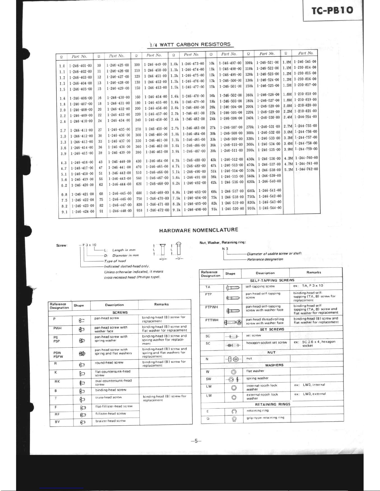
t/4
WATT CARBON
RE€!9r989
I{ARDWARE
NOMENCLATURE
Nui,
Warhw,
RGlsining
ring:
10
3x
N3
|
|
Di"-eter
ol
ueble
ærew
or shaft
I
I
Refercnce
detigBtion
I
'
a,
Lensth
in mm
>
D: Diameter
in mm
r1
iU
-O'-
Type of
head
t nd
icated slotted
-head
o nl
y
l)nless othe.wise
indicated,
it means
cross-ræ6sed
hæd
(Phillips
tYpe).
IF
ÏU
-oL
R6{€rsn@
06ignation
Shape
Dæription
Remarks
scREws
P
û-
pan-head
screw
binding-head
(B)
screw
for
replacement
PWH (t+
pan-head screw
with
msher
lace
binding-head
(8
I
screw
and
tlat washer
tor rePlacement
PS
PSP
I
pan-heôd
screw
wllh
spring
washer
binding-head
(8)
screw and
spriôg
washer
tor rePlace'
ment
PSW
PSPW
fiù
oan-heâd
screw
wrth
sprinq
aôd
tlal
washers
bind;ng-head
(B)
screw and
spring
and
tlat washers
tor
replacement
round-head
screw
biôding-head
(8)
screw
for
replacemenl
K
F
llat-countersu
nk-head
screw
RK
F
oval-cou
ntersunk'head
screw
B
F
binding'head
screw
T
F
truss-head
screw
binding-head
(B)
screw
tor
reglacement
tlal-f iil ister-head
screw
a-l
lrllister-head
screw
8V
ka
braizer-head
screw
Rgfer€næ
D6ignôlion
Shape
Oescriplion
Remarks
SELF.TAPPING
SCREWS
TA
\F-'--.'_
selt-lapprng
Screw
ex:
TA,P3x10
PTP
tlli:
pan-head
self-taPPiôg
screw
binding-head
self'
tapping
(TA,
Bl
screw
for
replacement
PTPWH
F
oan'head
self-taPPing
screw
with
washer
tace
bindinE-head
ælf
tapping
(TA,
B)
screw
ând
llat washer
for replacement
PTTWH
oan-head
thread'rolling
screw
wilh
washer
face
binding-head
SET
SCREWS
sc
-
€f-
set
screw
sc
-oæ
hexagon-socket
set screw
ex:
SC
2.6
x 4,
hexagon
sockel
NUT
N
-ft@ nut
WASHERS
lâr
v
flat washer
SW
-o$
spriôg
washel
LW
qJ
internal-1o01h
lock
washer
ex:
L!V3,
internal
LW
i-fJ-rern"t--ottt
toct
I
ex:
LW3,
external
I Aj I
washe,
I
tr
RETAINING
RINGS
E
e
retarnrng
rln9
o
griP-tYPe
retarnrng
rlng
TC.PB
I
O
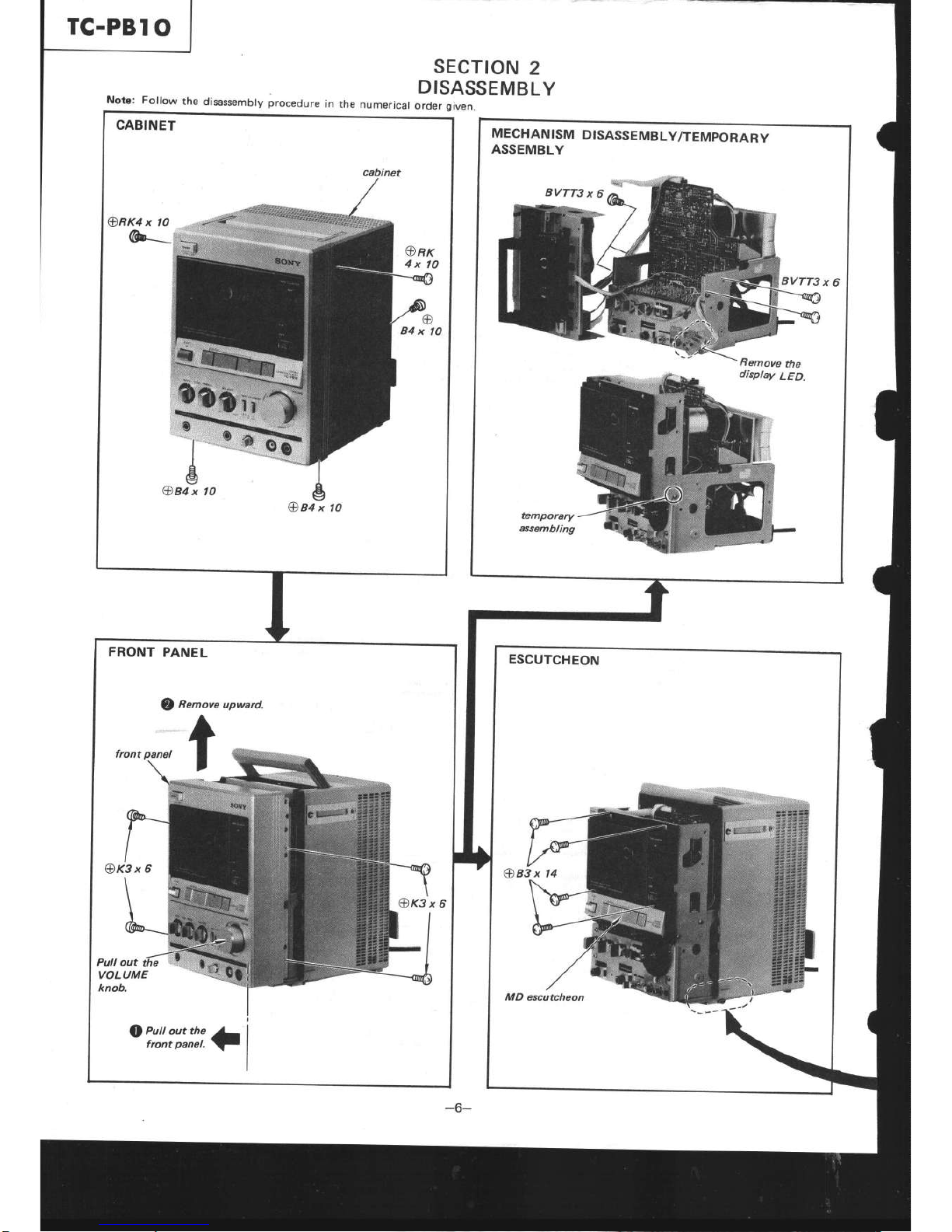
SECTION
2
Note: Fottow
rhe
disassembry procedure
in
the numeric.
-Or:rtâ:tEMBLY
cabinet
@
MECHANISM
DISASSEMBLY/TEMPORARY
ASSEMBLY
oi:!,i",:ili.1
-6-
TC-PBI
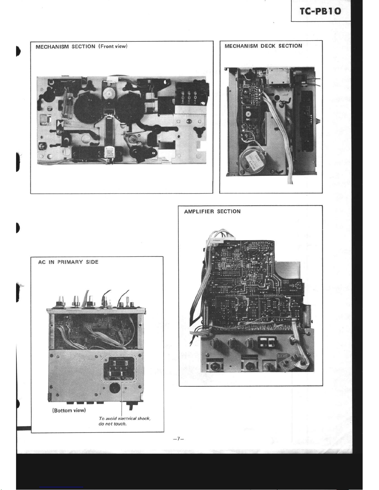
O
AC IN
PRIMARY SIDE
To avoid electrical shock,
do not touch.
MECHANISM
SECTION
(Front
view) MECHANISM
DECK SECTION
AMPLIFIER
SECTION

TC.PBI
O
l.
SECTION
3
ADJUSTM
ENTS
3.1.
MECHANICAL
ADJUSTMENTS
PRECAUTION
Clean
the
following parts
alcohol-moistened
swab
record/playback
head
erase
head
capstan
Demagnetize
the
playback
demagnetizer.
.Do
not
use
a magnetized
screwdriver
for
the
adiust
ments.
After the
adjustments,
apply suitable locking
compound
to the
parts
adjusted.
The
adjustments should
be
performed
with
the
rated
power
supply voltage
unless
otherwise
noted.
(
z.
with
a denatured-
pinch
roller
rubber
belts
id lers
head with
a head
5.
I
I
Torgue Measurement
and Back Tension
2.
If the specified
tained,
change
spring.
back-tension
torque is
not
the hooking
position
of
supply-reel
spindle
back-tension
lever
weaker
<+
stronger
Change
the
hooking
Position.
(
lgcm
per
one slide.)
Torque
Torque
meter Meter
reading
Forward
cQ-102C
30-60
g.cm
(0.42*0.83
oz.inch)
Fast
forward,
Rewind
cQ-201A
110-165
g.cm
(1.53-2.2
oz.inch)
Back tension cQ-102c
2.5-4.5
g.cm
(0.04-0.06
oz.inch)
TC-PBI
O
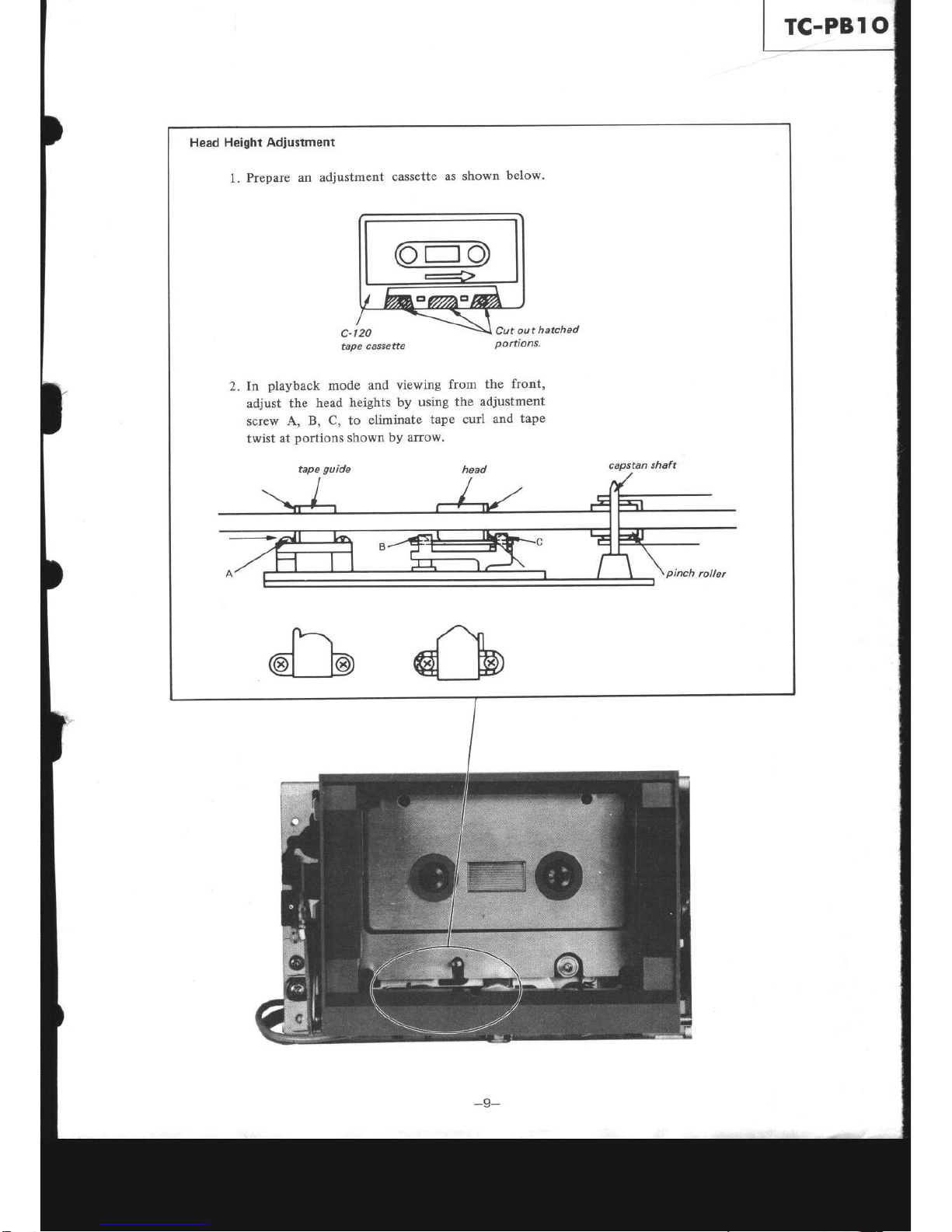
Head
Height Adjustment
l.
Prepare
an adjustment
cassette
as shown
below.
Cut
out
hatched
portions.
2. In
playback
mode
and
viewing
from
the
front,
adjust
the
head
heights
by
using the
adjustment
screw
A, B,
C, to
eliminate
tape
curl
and
tape
twist
at
portions
shown
bY arrow.
capstan
shaft
c-|20
tape
cassette
 Loading...