

Sony TCM-40DV Service Manual
TCM-40DV
SERVICE MANUAL
Ver 1.0 1999. 04
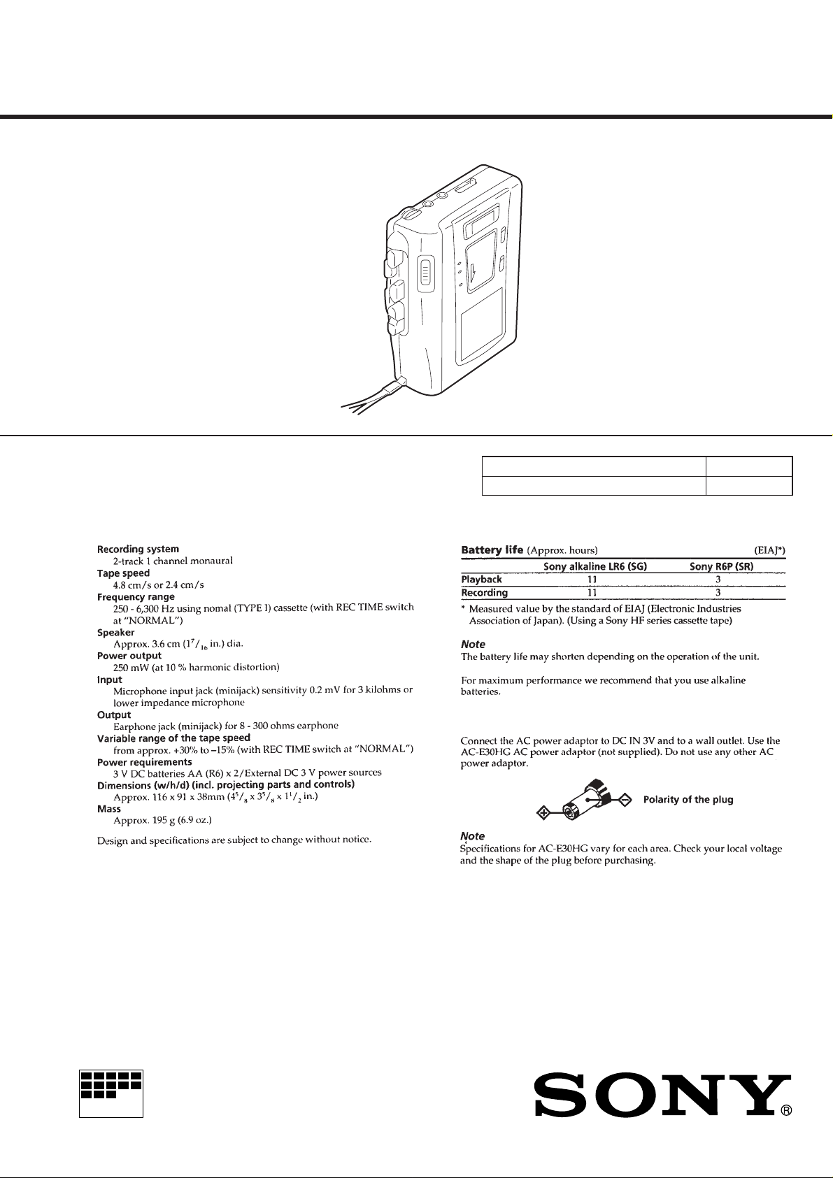
SPECIFICA TIONS
US Model
Canadian Model
AEP Model
E Model
Model Name Using Similar Mechanism TCM-36
T ape Transport Mechanism Type MT-40-118
MICROFILM
CASSETTE-CORDER
SECTION 1
SERVICING NOTES
TABLE OF CONTENTS
1. SERVICING NOTES............................................... 2
2. GENERAL ................................................................... 3
3. DISASSEMBLY ......................................................... 4
4. MECHANICAL ADJUSTMENTS....................... 6
5. ELECTRICAL ADJUSTMENTS......................... 7
6. DIAGRAMS
6-1. Block Diagram ................................................................ 8
6-2. Printed Wiring Boards .................................................... 10
6-3. Schematic Diagram ......................................................... 13
7. EXPLODED VIEWS................................................ 19
8. ELECTRICAL PARTS LIST ............................... 22
In this set, the S102 (POWER) detects REC/PLAYBACK on.
It is mounted on the MAIN board, and therefore the REC/PLAYBACK on cannot be detected with the MAIN board removed.
When making an operation check and voltage check of mechanical deck with the MAIN board removed, fix the S102 at turn on.
– MAIN BOARD (Conductor Side) –
S102
on
Flexible Circuit Board Repairing
• Keep the temperature of the soldering iron around 270 ˚C during repairing.
• Do not touch the soldering iron on the same conductor of the
circuit board (within 3 times).
• Be careful not to apply force on the conductor when soldering
or unsoldering.
Notes on chip component replacement
• Never reuse a disconnected chip component.
• Notice that the minus side of a tantalum capacitor may be damaged by heat.
– 2 –
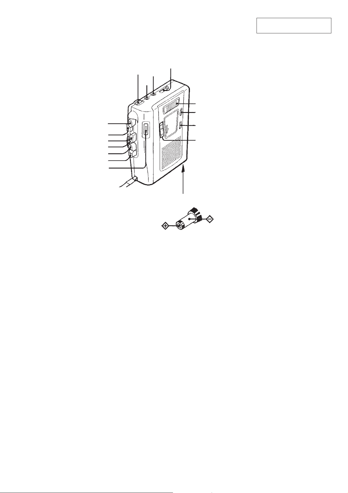
• Location of Controls
r
p
SPEED CONTROL
0
9
REW/REVIEW
)
FF/CUE
PAUSE
REC
STOP
PLAY
c
VOL
EAR
MIC
SECTION 2
GENERAL
TAPE COUNTER
Flat mic
Micropohone plat
REC TIME
VOR
BATT/REC/
i
This section is extracted from
instruction manual.
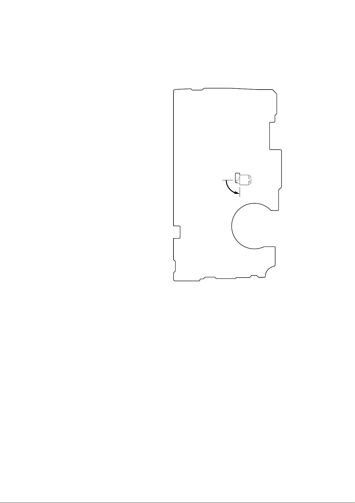
DC IN 3 V
– 3 –
• This set can be disassembled in the order shown below.
SECTION 3
DISASSEMBLY
Set Cabinet (Rear), Cassette Lid MAIN Board, Mechanism Deck
Note: Follow the disassembly procedure in the numerical order given.
(MT-40-118)
CABINET (REAR), CASSETTE LID
8
cassette lid
7
boss
3
claw
Belt
9
6
flexible board
(CN102)
cassette spring
2
screw
3
two claws
7
boss
5
4
cabinet (rear)
strap
3
claw
1
three screws (B1.7 × 10)
– 4 –

MAIN BOARD, MECHANISM DECK (MT-40-118)
REC lever
screw
(1.7)
S101
screw
(M1.4)
MAIN board
Note: On installation MAIN
board adjust the S105
and button (pause).
6
three screws
(IB lock)
button (pause)
S105
7
claw
8
mechanism deck
(MT-40-118)
1
Remove four solders
of motor leads (M901).
NOTE FOR INSTALLATION
• MAIN BOARD
On installation MAIN board
adjust the S101 and REC lever.
5
MAIN board
2
Remove the two solders
of the head lead (HRP901).
4
screw
(M1.4)
3
screw
(1.7)
– 5 –
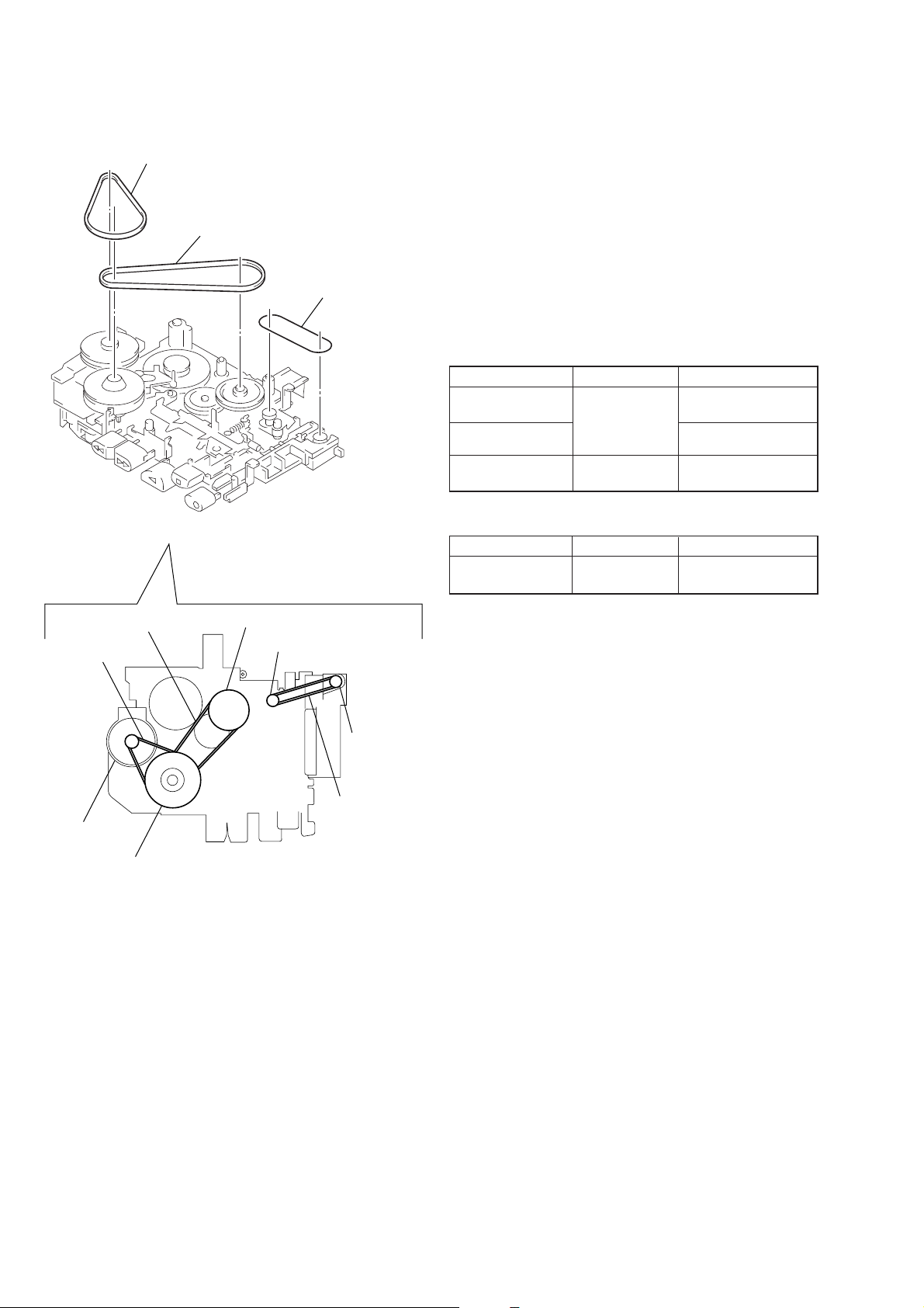
SECTION 4
MECHANICAL ADJUSTMENTS
BELT
1
capstan belt
2
FR belt
3
counter belt
1. Clean the following parts with a denatured-alcohol-moistened
swab:
record/playback head pinch roller
erase head rubber belt
capstan
2. Demagnetize the record/playback head with a head demagnetizer. (Do not bring the head demagnetizer close to the erase
head.)
3. Do not use a magnetized screwdriver for the adjustments.
4. After the adjustments, apply suitable locking compound to the
parts adjusted.
5. The adjustments should be performed with the rated power
supply voltage (2.5 V) unless otherwise noted.
Torque Measurement
Mode Torque Meter Meter Reading
FWD
Forward Back 1.0 – 4.5 g•cm
Tension (0.014 – 0.063 oz•inch)
FF, REW CQ-201B
CQ-102C
22 – 48 g•cm
(0.31 – 0.67 oz•inch)
more than 50 g•cm
(more than 0.69 oz•inch)
Tape T ension Measurement
Mode Tension Meter Meter Reading
FWD CQ-403A
more than 50 g
(more than 1.76 oz)
capstan belt
motor DC
FR belt
flywheel assy
pulley (FR) assy
pulley counter
counter tape
counter belt
– 6 –
 Loading...