

Page 1
TCM-40DV
SERVICE MANUAL
Ver 1.0 1999. 04
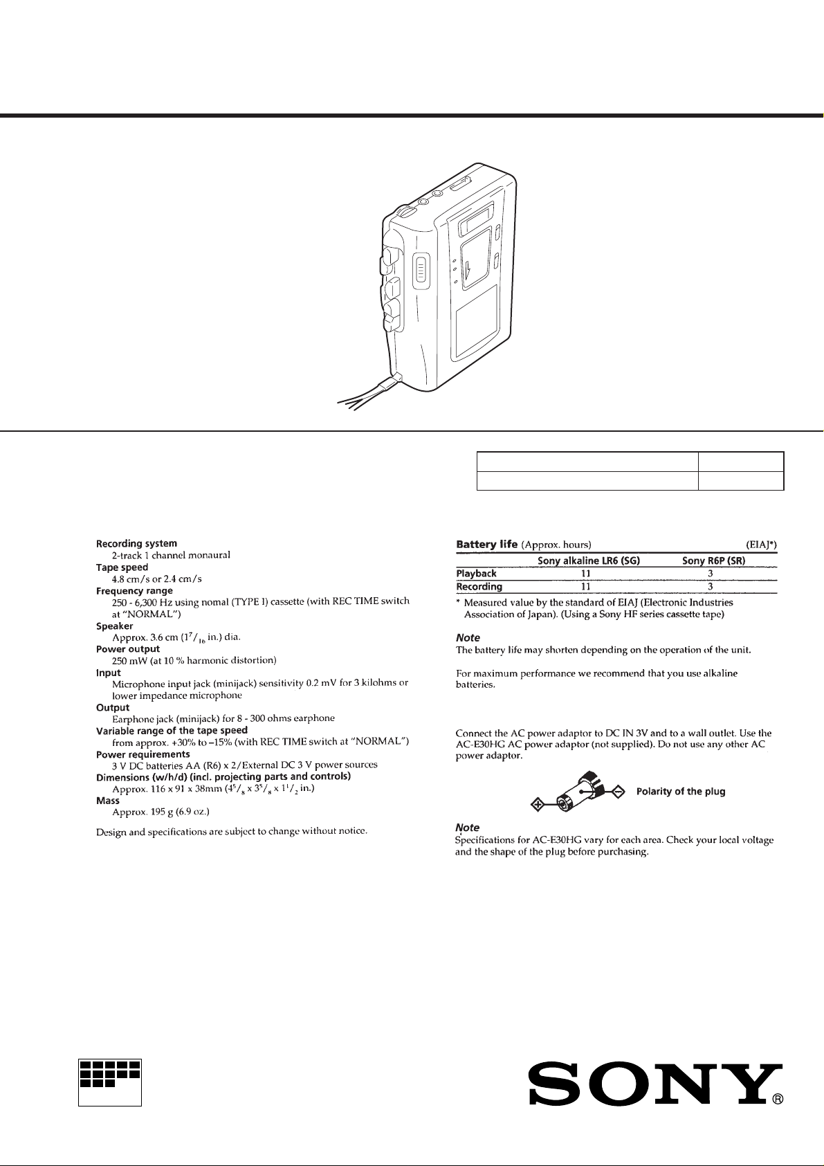
SPECIFICA TIONS
US Model
Canadian Model
AEP Model
E Model
Model Name Using Similar Mechanism TCM-36
T ape Transport Mechanism Type MT-40-118
MICROFILM
CASSETTE-CORDER
Page 2
SECTION 1
SERVICING NOTES
TABLE OF CONTENTS
1. SERVICING NOTES............................................... 2
2. GENERAL ................................................................... 3
3. DISASSEMBLY ......................................................... 4
4. MECHANICAL ADJUSTMENTS....................... 6
5. ELECTRICAL ADJUSTMENTS......................... 7
6. DIAGRAMS
6-1. Block Diagram ................................................................ 8
6-2. Printed Wiring Boards .................................................... 10
6-3. Schematic Diagram ......................................................... 13
7. EXPLODED VIEWS................................................ 19
8. ELECTRICAL PARTS LIST ............................... 22
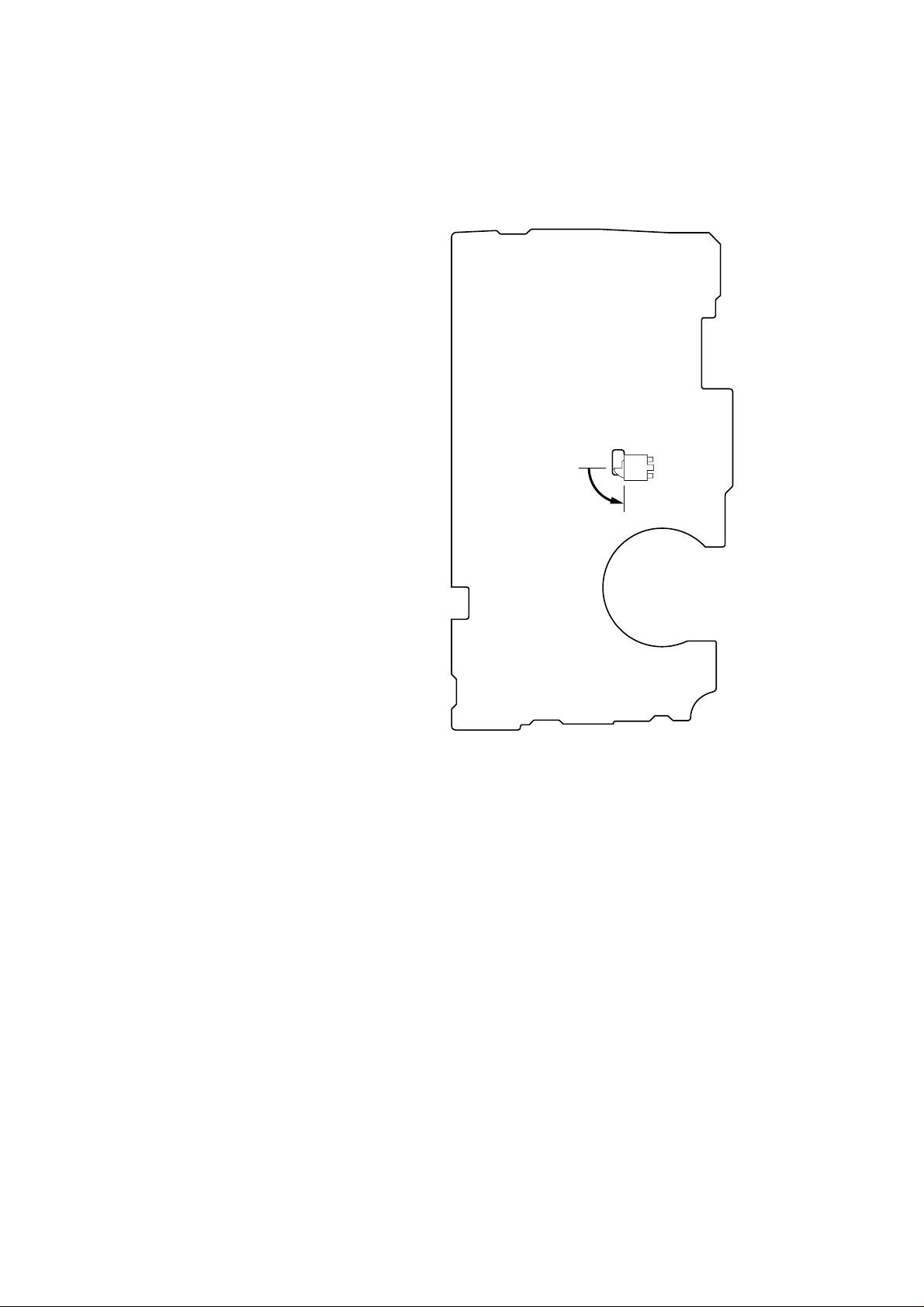
In this set, the S102 (POWER) detects REC/PLAYBACK on.
It is mounted on the MAIN board, and therefore the REC/PLAYBACK on cannot be detected with the MAIN board removed.
When making an operation check and voltage check of mechanical deck with the MAIN board removed, fix the S102 at turn on.
– MAIN BOARD (Conductor Side) –
S102
on
Flexible Circuit Board Repairing
• Keep the temperature of the soldering iron around 270 ˚C during repairing.
• Do not touch the soldering iron on the same conductor of the
circuit board (within 3 times).
• Be careful not to apply force on the conductor when soldering
or unsoldering.
Notes on chip component replacement
• Never reuse a disconnected chip component.
• Notice that the minus side of a tantalum capacitor may be damaged by heat.
– 2 –
Page 3
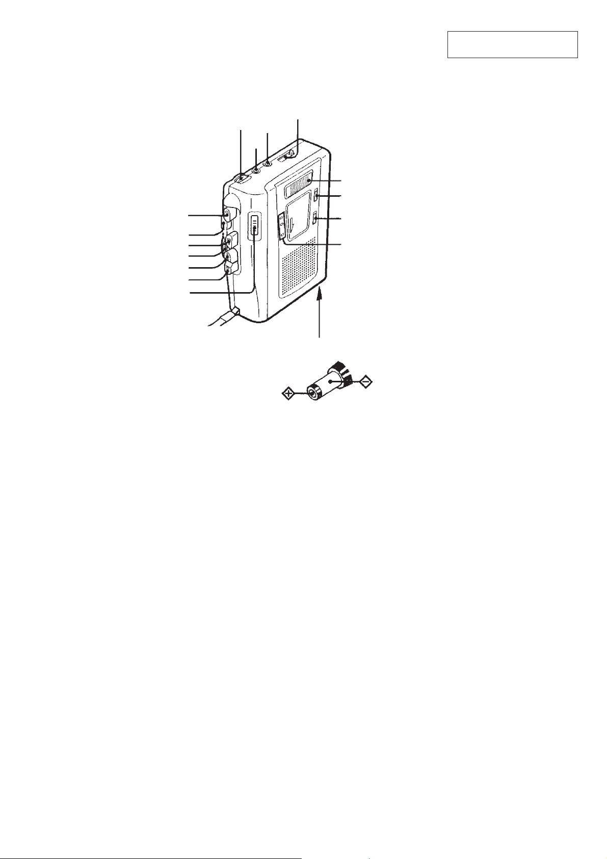
• Location of Controls
r
p
SPEED CONTROL
0
9
REW/REVIEW
)
FF/CUE
PAUSE
REC
STOP
PLAY
c
VOL
EAR
MIC
SECTION 2
GENERAL
TAPE COUNTER
Flat mic
Micropohone plat
REC TIME
VOR
BATT/REC/
i
This section is extracted from
instruction manual.
DC IN 3 V
– 3 –
Page 4
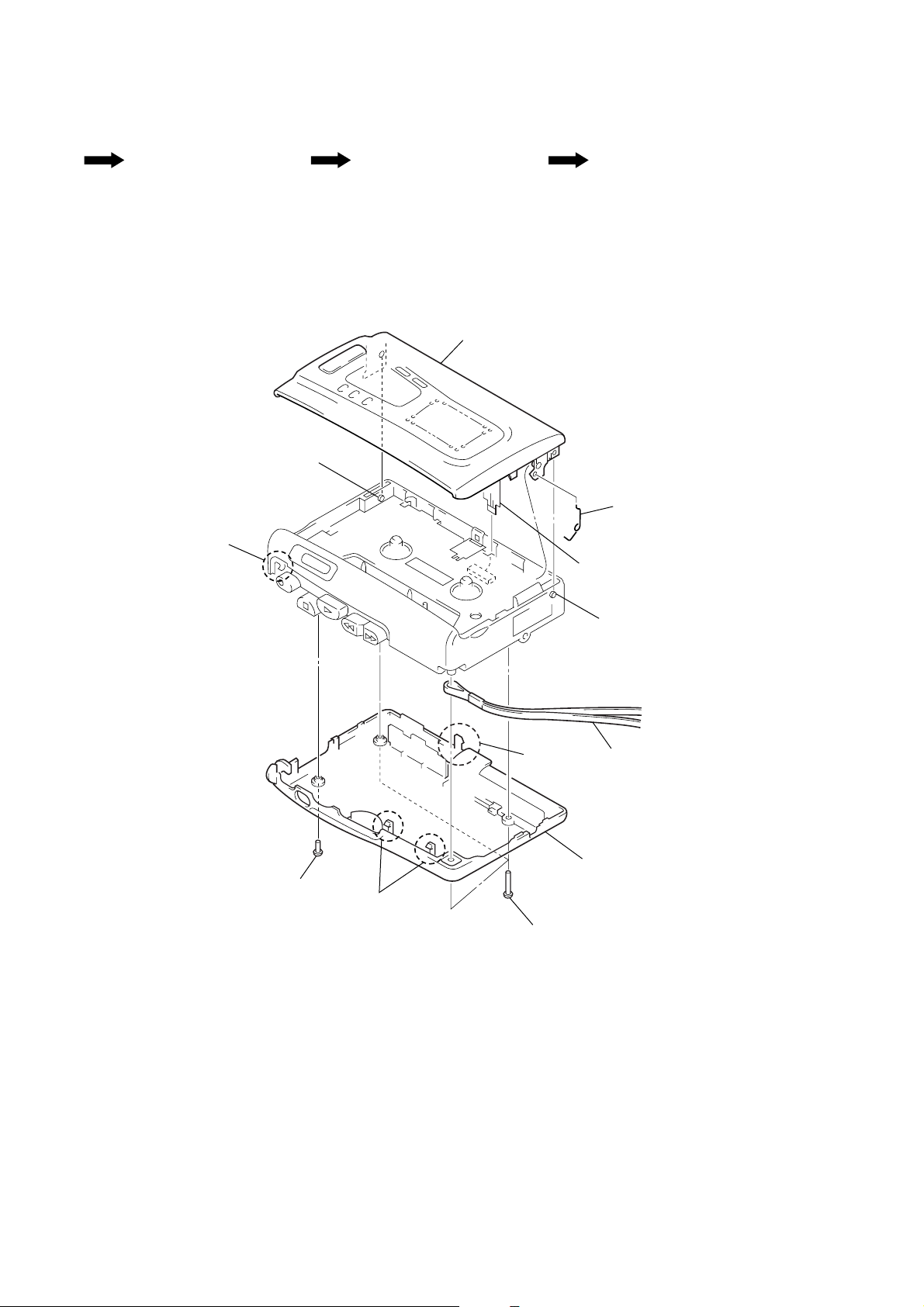
• This set can be disassembled in the order shown below.
SECTION 3
DISASSEMBLY
Set Cabinet (Rear), Cassette Lid MAIN Board, Mechanism Deck
Note: Follow the disassembly procedure in the numerical order given.
(MT-40-118)
CABINET (REAR), CASSETTE LID
8
cassette lid
7
boss
3
claw
Belt
9
6
flexible board
(CN102)
cassette spring
2
screw
3
two claws
7
boss
5
4
cabinet (rear)
strap
3
claw
1
three screws (B1.7 × 10)
– 4 –
Page 5
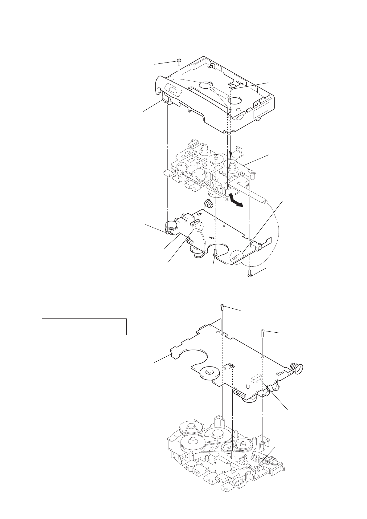
MAIN BOARD, MECHANISM DECK (MT-40-118)
REC lever
screw
(1.7)
S101
screw
(M1.4)
MAIN board
Note: On installation MAIN
board adjust the S105
and button (pause).
6
three screws
(IB lock)
button (pause)
S105
7
claw
8
mechanism deck
(MT-40-118)
1
Remove four solders
of motor leads (M901).
NOTE FOR INSTALLATION
• MAIN BOARD
On installation MAIN board
adjust the S101 and REC lever.
5
MAIN board
2
Remove the two solders
of the head lead (HRP901).
4
screw
(M1.4)
3
screw
(1.7)
– 5 –
Page 6

SECTION 4
MECHANICAL ADJUSTMENTS
BELT
1
capstan belt
2
FR belt
3
counter belt
1. Clean the following parts with a denatured-alcohol-moistened
swab:
record/playback head pinch roller
erase head rubber belt
capstan
2. Demagnetize the record/playback head with a head demagnetizer. (Do not bring the head demagnetizer close to the erase
head.)
3. Do not use a magnetized screwdriver for the adjustments.
4. After the adjustments, apply suitable locking compound to the
parts adjusted.
5. The adjustments should be performed with the rated power
supply voltage (2.5 V) unless otherwise noted.
Torque Measurement
Mode Torque Meter Meter Reading
FWD
Forward Back 1.0 – 4.5 g•cm
Tension (0.014 – 0.063 oz•inch)
FF, REW CQ-201B
CQ-102C
22 – 48 g•cm
(0.31 – 0.67 oz•inch)
more than 50 g•cm
(more than 0.69 oz•inch)
Tape T ension Measurement
Mode Tension Meter Meter Reading
FWD CQ-403A
more than 50 g
(more than 1.76 oz)
capstan belt
motor DC
FR belt
flywheel assy
pulley (FR) assy
pulley counter
counter tape
counter belt
– 6 –
Page 7

SECTION 5
r
ELECTRICAL ADJUSTMENTS
TCM-40DV
SECTION 6
DIAGRAMS
Setting:
• Supplied voltage: 2.5 V
• Switch and control position
VOL contorl (RV401) : mechanical center
PAUSE switch (S105) : OFF
SPEED CONTROL (RV605): center click
VOR switch (S104) : OFF
Test T ape
Type Signal Used for
P-4-A063 6.3 kHz, –10 dB head azimuth adjustment
WS-48A 3 kHz, 0 dB tape speed adjustment
0 dB=0.775 V
Record/Playback Head Azimuth Adjustment
Mode: playback
test tape
P-4-A063
(6.3 kHz, –10 dB)
set
32
level mete
Ω
+
–
EAR jack (J101)
Procedure:
1. Turn the adjustment screw to obtain the maximum reading on
level meter.
Note: Several peaks may appear, but take the maximum.
2. After the adjustment, lock the adjustment screw with suitable
locking compound.
Adjustment Location:
adjustment screw
Press the
button.
(
Tape Speed Adjustment
Mode: playback
test tape
WS-48A
(3 kHz, 0 dB)
32
set
EAR jack (J101)
frequency
counter
Ω
+
–
Procedure:
1. Set [RECTIME] switch (S601) to NORMAL (4.8 cm/s) posi-
tion, and playback the tape (WS-48A) .
2. Adjust R V604 so that frequenc y counter reading becomes 3,040
Hz.
Specification values: 3,030 to 3,050 Hz
3. Set [RECTIME] switch (S601) to DOUBLE (2.4 cm/s) position.
4. Playback the tape from the beginning for two minutes, then
adjust R V606 so that frequency counter reading becomes 1,540
Hz.
Specification values: 1,535 to 1,545 Hz
Confirm that deflection of the frequency counter reading between
the beginning and the end of tape is within 0.5% (NORMAL:
approx. 15.2 Hz, DOUBLE: approx. 7.6 Hz) .
Adjustment Location:
– MAIN BOARD (Conductor Side) –
J101
Tape Speed Adjustment
RV604
Tape Speed Adjustment
(Normal Speed)
RV606
(Double Speed)
6-1. BLOCK DIAGRAM
MIC101
(MIC)
J102
MIC
(PLUG IN POWER)
S101
(REC/PB)
PB
REC
HRP901
(REC/PB)
HE901
(ERASE)
S101 (1/6)
M901
(CAPSTAN/REEL)
WV
Q101
AGC
CONTROL
S101 (4/6)
VREF
U
MOTOR BRAKE
SWITCH
Q603, 604
MOTOR BRAKE
CONTROL SWITCH
Q601, 602
D602
15
20
1
2
MIC IN
28
EQ IN
29
ALC
CONT
5
REC OUT
4
COMPARATOR
OUT
UOUT
VOUT
WOUT
MIC AMP, REC/PB EQ AMP
IC101 (1/2)
MIC
AMP
EQ
AMP
ALC
REC
AMP
IN+
13
+
VSP
–
14
SPEED
CONTROL
MOTOR
DRIVE
CIRCUIT
SWITCH &
LOGIC
CIRCUIT
REC IN
RV605
SPEED
CONTROL
RV605
PRE
OUT
PRE
NF
CIRCUIT
2
1
3
S101 (6/6)
(REC/PB)
REC
TH602
S101 (6/6)
OSC
OSC
7
Q104
PB EQ
SWITCH
NF
REC EQ
SWITCH
PB
VREF
REFERENCE
VOLTAGE
CAPSTAN/REEL
MOTOR DRIVE
IC601
Q103
BIAS
12
VREF
+
REC B+
THP606
RV604
S/S
VCC
REC B+
RV606
11
18
VOR LOW
SWITCH
Q402
S601
REC TIME
DOUBLE
NORMAL
RV604, 606
TAPE SPEED
BATTERY B+
RV101
VOL
REC B+
BUFFER
Q102
VOR ON
SWITCH
Q403
S401
VOR
HL
MOTOR CONTROL
SWITCH
Q605
REC B+
OFF
REC B+
PB B+
VREF
REFERENCE VOLTAGE
S101 (2/6)
(REC/PB)
PB
REC
VOR OFF
SWITCH
REC B+
POWER ON B+
S101 (5/6)
(REC/PB)
MUTE SWITCH
Q107, 108
Q401
PB
REC
POWER AMP, VOR CONTROL,
REGULATOR, CAPSTAN/REEL MOTOR DRIVE
POW IN
11
VOR
DELAY
7
R/P
SW
23
GVN OUT
16
GVN VREF
19
GVN CONT
20
MIC
VCC
26
VREF
27
REC/PB
REGULATOR
REFERENCE
VOLTAGE
GENERATOR
VOX
IC101 (2/2)
POWER
AMP
MOTOR
DRIVER
POW OUT 1
POW OUT 2
PAUSE
MUTE
RIPPLE
FILTER
VOLTAGE DETECT
IC501
LED
DRIVE
PAUSE
MUTE
12
14
24
22
21
VCC
VOICE
MIRROR
Q503
D603
15
Q404
SWITCHING
Q502
MUTE SWITCH
PB B+
PB B+
MUTE
SWITCH
Q109, 110
POWER ON B+
S101 (3/6)
(REC/PB)
PB
REC
D503
BATT • •
S105
PAUSE c
OFF
ON
POWER ON B+
D502
BATT • /REC
REC B+
PB B+
S102
(POWER)
BATTERY B+
• SIGNAL PATH
Q106
REC/PB
MONITOR LEVEL
SWITCHING
: PLAY
: RECORD
SP901
(SPEAKER)
J101
EAR
PB B+
DRY BATTERY
(IEC DESIGNATION R6)
–
SIZE “AA”
2PCS. 3V
CN101
DC IN 3V
+
VCC
D501
05
i
LED DRIVE
Q501
OUT
BOOSTER
4
CIRCUIT
COMPARATOR
7
VS
6
– 7 –
– 8 –
– 9 –
Page 8

Page 9

6-3. SCHEMATIC DIAGRAM • See page 17 for IC Block Diagrams.
TCM-40DV
– 13 –
– 14 –
– 15 –
Note on Schematic Diagram:
• All capacitors are in µF unless otherwise noted. pF: µµF
50 WV or less are not indicated except for electrolytics
and tantalums.
• All resistors are in Ω and 1/
specified.
• C : panel designation.
• U : B+ Line.
• H : adjustment for repair.
• Total current is measured with no cassette installed.
• Power voltage is dc 3 V and fed with regulated dc power
supply from external power voltage jack.
• Voltages and waveforms are dc with respect to ground
under no-signal conditions.
no mark : PLAY
< > :RECORD
• Voltages are taken with a V OM (Input impedance 10 MΩ).
Voltage variations may be noted due to normal production tolerances.
• Signal path.
E : PLAY
a : RECORD
4
W or less unless otherwise
– 16 –
Page 10

SECTION 7
EXPLODED VIEWS
• IC Block Diagrams
IC101 LA4168ML-TE-L
PRE GND
EQ IN
MIC IN
2.2k
+
–
EQ
300k
1
PRE NF
2
PRE OUT
+
–
MIC
3
REC IN
30k
+
4
Vref OUT
2k
–
20k
REC
REC OUT
MIC VCC
5
ALC CONT
R, F OUT
ALC
6
VOX CONT
LED DRIVER/P SW
VOX
SPEED
VOX
7
VOX DELAY
PAUSE
MIC
VCC
+
–
Vref
8
GNV SPEED UP
PAUSE
21222324252627282930
9
10
AUT STOP CONT
P/R MUTE
11
AUT STOP IN
GVN CONT
PWR IN
GVN Vref
1
12
PWR OUT1
181920
R/P
R, F
POWER
13
Vs
PWR GND
GVN GND
17
GVN
2
14
PWR OUT2
16
15
GVN OUT
Vcc
IC601 LB1877V-TLM
VOUT
1
2
WOUT
3
PGND
WB
4
VB
5
6
UB
OSC
COM
GND
7
8
9
R1
10
OSC
CIRCUIT
STARTING
DETECT
PRE DRIVER
SOFT SWITCH
COMMUNICATION
STARTING LOGIC
WAVEFORM DETECT
SPEED
CONTROL
CURRENT
CONTROL
DIRECTION
CONTROL
OUTPUT
BIAS
SPEED CONTROL
REFERENCE VOLTAGE
REFERENCE
VOLTAGE
–
+
COMPARATOR
POWER
SUPPLY
BIAS
NOTE:
• -XX and -X mean standardized parts, so they
may have some difference from the original
20
UOUT
19
DR
VCC
18
17
LB
16
FC
one.
• Color Indication of Appearance Parts
Example:
KNOB, BALANCE (WHITE) . . . (RED)
↑↑
Parts Color Cabinet's Color
15
OUT
VSP
14
IN+
13
(1) CABINET SECTION
• Items marked “*” are not stocked since they
are seldom required for routine service. Some
delay should be anticipated when ordering
these items.
• The mechanical parts with no reference number in the exploded views are not supplied.
• Accessories and packing materials are given
in the last of the electrical parts list.
(2) MECHANISM DECK SECTION-1
(MT-40-118)
62
61
63
HRP901
59
74
65
24
VREF
12
9
(including MIC101)
60
64
66
10
S/S
11
8
11
23
12
27
13
58
67
57
68
72
69
75
26
7
23
6
SP901
15
56
78
14
1
71
55
MT-40-118
5
25
17
16
54
53
M901
70
IC501 MM1251BFBE
NC
VCC
VS
678 5
–
+
+
–
21 3 4
CT
NC
GND
HYS
BOOSTER
CIRCUIT
OUT
4
3
23
23
Ref. No. Part No. Description Remark
1 3-318-382-31 SCREW (1.7), TAPPING
2 3-345-648-51 SCREW (M1.4), TOOTHED LOCK
* 3 A-3021-227-A MAIN BOARD, COMPLETE
4 3-008-612-01 TERMINAL, PLUS
5 3-924-750-01 TERMINAL, MINUS
6 3-924-744-01 SPRING (CLAW DETECTION), TENSION
7 3-018-311-01 CLAW, ERASING PREVENTION
8 3-018-310-11 BUTTON (PAUSE)
9 4-969-980-21 SCREW (IB LOCK)
10 3-578-101-41 PLATE, ORNAMENTAL
11 3-018-307-62 CABINET (FRONT)
12 A-3021-225-A LED BOARD, COMPLETE
13 3-936-424-01 SPRING, CASSETTE
14 4-017-441-01 CUSHION (B)
2
1
23
22
21
20
18
19
Ref. No. Part No. Description Remark
* 15 3-924-757-01 BRACKET (SPEAKER)
16 3-924-761-01 STRAP
17 3-018-309-11 LID, BATTERY CASE
18 3-018-308-51 CABINET (REAR)
19 3-018-312-01 FOOT (A)
20 3-334-565-11 SCREW (B1.7X10), TAPPING
21 3-023-856-01 FOOT (B)
22 3-907-531-01 SCREW
23 3-831-441-99 SPACER, KNOB
24 X-3377-425-1 LID SUB ASSY, CASSETTE (including MIC101)
25 3-026-183-01 CUSHION (BATTEY CASE LID)
26 3-318-382-04 SCREW (1.7), TAPPING
27 1-672-147-11 CONNECTION FLEXIBLE BOARD
SP901 1-505-838-11 SPEAKER (3.6cm)
51
52
73
77
Ref. No. Part No. Description Remark
51 X-3370-386-1 PINCH ROLLER ASSY
52 3-925-146-01 BUTTON (FF) ())
53 3-925-147-01 BUTTON (REW) (0)
54 3-925-148-01 BUTTON (PLAY) (()
55 3-925-145-11 BUTTON (REC) (r)
56 3-936-409-01 BUTTON (STOP) (p)
57 1-548-582-11 COUNTER, TAPE (SMALL TYPE)
58 3-924-625-01 LEVER (HEAD)
59 3-924-645-01 BRACKET (HEAD)
60 3-924-685-01 SPRING (AZIMUTH), COMPRESSION
61 3-704-197-31 SCREW (IB LOCK)
62 3-375-135-01 SCREW (1.4), SPECIAL
63 3-376-177-01 SCREW (M1.4X3.8)
64 3-925-107-01 SPRING (IDLER), COMPRESSION
65 3-924-637-01 GEAR (FF)
66 3-924-673-01 GEAR (S REEL)
76
81
Ref. No. Part No. Description Remark
67 3-924-674-01 SPRING (B. T), COMPRESSION
68 3-924-641-01 GEAR (T REEL)
69 3-936-582-03 SPRING (GROUND), TORSION
70 3-924-681-01 BELT (CAPSTAN)
71 1-649-600-11 MOTOR FLEXIBLE BOARD
72 3-376-407-01 SCREW (M1.4) (MOTOR)
73 3-034-903-01 SPRING (POWER TENSION), TENSION
74 3-348-160-11 SCREW (M1.4X1.6), PRECISION PAN
75 3-018-522-01 COUNTER, BRACKET
76 3-924-675-01 PULLEY (COUNTER)
77 3-924-683-01 BELT (COUNTER)
78 3-376-407-01 SCREW (M1.4)
80 3-561-685-01 SHEET (C), INSULATING
81 4-969-980-21 SCREW (IB LOCK)
HRP901 1-500-073-51 HEAD, MAGNETIC (RECORD/PLAYBACK)
M901 1-698-875-11 MOTOR, DC (CAPSTAN/REEL) (WITH PULLEY)
– 17 –
– 18 –
– 19 –
– 20 –
Page 11

(3) MECHANISM DECK SECTION-2
(MT-40-118)
109
107
108
113
112
111110
101
116
114
127
117
not
supplied
132
119
121
115
106
105
104
103
102
102
130
101
129
131
Ref. No. Part No. Description Remark
101 3-321-483-11 RING, RETAINING (0.25)
102 3-701-437-51 WASHER
103 X-3372-171-1 FLYWHEEL ASSY
104 3-924-623-01 LEVER (PLAY)
105 3-924-621-01 LEVER (REW)
118
120
123
122
124
133
not
supplied
HE901
126
128
125
Ref. No. Part No. Description Remark
118 3-035-368-01 SPRING (PR2), TORSION
119 3-924-684-01 SPRING (LOCK PLATE), TENSION
120 3-924-619-01 LEVER (SW)
121 3-924-639-01 LEVER (CR)
122 3-924-618-01 LEVER (LOCK)
106 3-924-620-01 LEVER (FF)
107 X-3370-388-1 TABLE ASSY, FELT
108 3-924-642-01 SPRING (FR), TORSION
109 3-924-629-01 LEVER (DETECTION)
110 3-925-207-01 SPRING (SHUT. OFF), TENSION
111 3-924-630-01 LEVER (S. OFF)
112 X-3370-387-1 LEVER ASSY, IDLER
113 3-924-682-01 BELT (FR)
114 X-3370-385-1 PULLEY (FR) ASSY
115 3-924-628-01 LEVER (FR)
116 3-924-633-01 SPRING (STOP), TENSION
117 3-924-622-01 LEVER (STOP)
123 3-925-208-01 SPRING (REC), TENSION
124 3-924-624-01 LEVER (REC)
125 X-3377-249-3 CHASSIS SUB ASSY
126 3-924-613-01 GEAR (FR)
127 3-024-378-21 SPRING (FR LEVER), TORSION
128 3-703-925-21 SCREW (M1.4)
129 3-936-405-01 LEVER (RELEASE)
130 3-578-242-11 WASHER
131 3-014-082-01 SPACER
132 3-321-483-31 RING, RETAINING
133 3-704-197-91 SCREW (IB LOCK)
HE901 1-500-515-11 HEAD, MAGNETIC (ERASE)
– 21 –
Page 12

LED MAIN
SECTION 8
ELECTRICAL PARTS LIST
NOTE:
• Due to standardization, replacements in the
parts list may be different from the parts specified in the diagrams or the components used
on the set.
• -XX and -X mean standardized parts, so they
may have some difference from the original
one.
• RESISTORS
All resistors are in ohms.
METAL: Metal-film resistor.
METAL OXIDE: Metal oxide-film resistor.
F: nonflammable
Ref. No. Part No. Description Remark Ref. No. Part No. Description Remark
A-3021-225-A LED BOARD, COMPLETE
********************
1-672-147-11 CONNECTION FLEXIBLE BOARD
< DIODE >
D501 8-719-057-99 LED SML-211YT-T86 (i)
D502 8-719-059-96 LED SML-210LT-T86 (BATT r, REC)
D503 8-719-059-96 LED SML-210LT-T86 (BATT rr)
< SWITCH >
S401 1-692-605-31 SWITCH, SLIDE (VOR)
S601 1-571-277-51 SWITCH, SLIDE (REC TIME)
**************************************************************
* A-3021-227-A MAIN BOARD, COMPLETE
*********************
• Items marked “*” are not stocked since they
are seldom required for routine service.
Some delay should be anticipated when ordering these items.
• SEMICONDUCTORS
In each case, u: µ, for example:
uA. . : µA. . uPA. . : µPA. .
uPB. . : µPB. . uPC. . : µPC. .
uPD. . : µPD. .
• CAPACITORS
uF: µF
• COILS
uH: µH
C127 1-124-434-00 ELECT 220uF 20% 4V
C128 1-124-433-00 ELECT 100uF 20% 4V
C129 1-126-153-11 ELECT 22uF 20% 6.3V
C130 1-163-035-00 CERAMIC CHIP 0.047uF 50V
C132 1-164-346-11 CERAMIC CHIP 1uF 16V
C134 1-164-182-11 CERAMIC CHIP 0.0033uF 10% 50V
C136 1-164-346-11 CERAMIC CHIP 1uF 16V
C137 1-164-346-11 CERAMIC CHIP 1uF 16V
C138 1-164-346-11 CERAMIC CHIP 1uF 16V
C140 1-163-009-11 CERAMIC CHIP 0.001uF 10% 50V
C141 1-163-009-11 CERAMIC CHIP 0.001uF 10% 50V
C142 1-163-009-11 CERAMIC CHIP 0.001uF 10% 50V
C145 1-163-009-11 CERAMIC CHIP 0.001uF 10% 50V
C146 1-163-009-11 CERAMIC CHIP 0.001uF 10% 50V
C401 1-126-153-11 ELECT 22uF 20% 6.3V
C402 1-124-257-00 ELECT 2.2uF 20% 50V
When indicating parts by reference
number, please include the board.
3-008-612-01 TERMINAL, PLUS
< CAPACITOR >
C101 1-164-004-11 CERAMIC CHIP 0.1uF 10% 25V
C102 1-164-161-11 CERAMIC CHIP 0.0022uF 10% 100V
C103 1-107-682-11 CERAMIC CHIP 1uF 10% 16V
C104 1-135-151-21 TANTALUM CHIP 4.7uF 20% 4V
C105 1-135-151-21 TANTALUM CHIP 4.7uF 20% 4V
C106 1-163-009-11 CERAMIC CHIP 0.001uF 10% 50V
C107 1-163-077-00 CERAMIC CHIP 0.1uF 10% 25V
C108 1-163-017-00 CERAMIC CHIP 0.0047uF 5% 50V
C109 1-163-001-11 CERAMIC CHIP 220PF 10% 50V
C110 1-109-982-11 CERAMIC CHIP 1uF 10% 10V
C111 1-135-151-21 TANTALUM CHIP 4.7uF 20% 4V
C112 1-164-182-11 CERAMIC CHIP 0.0033uF 10% 50V
C113 1-164-005-11 CERAMIC CHIP 0.47uF 25V
C114 1-164-346-11 CERAMIC CHIP 1uF 16V
C115 1-164-161-11 CERAMIC CHIP 0.0022uF 10% 100V
C116 1-164-346-11 CERAMIC CHIP 1uF 16V
C117 1-163-009-11 CERAMIC CHIP 0.001uF 10% 50V
C118 1-164-489-11 CERAMIC CHIP 0.22uF 10% 16V
C119 1-164-489-11 CERAMIC CHIP 0.22uF 10% 16V
C120 1-126-153-11 ELECT 22uF 20% 6.3V
C121 1-163-205-00 CERAMIC CHIP 0.001uF 5% 50V
C124 1-124-259-11 ELECT 4.7uF 20% 16V
C125 1-124-434-00 ELECT 220uF 20% 4V
C126 1-164-346-11 CERAMIC CHIP 1uF 16V
C403 1-164-505-11 CERAMIC CHIP 2.2uF 16V
C404 1-135-151-21 TANTALUM CHIP 4.7uF 20% 4V
C501 1-164-004-11 CERAMIC CHIP 0.1uF 10% 25V
C502 1-135-201-11 TANTALUM CHIP 10uF 20% 4V
C503 1-164-346-11 CERAMIC CHIP 1uF 16V
C504 1-164-161-11 CERAMIC CHIP 0.0022uF 10% 100V
C505 1-124-233-11 ELECT 10uF 20% 16V
C601 1-164-505-11 CERAMIC CHIP 2.2uF 16V
C602 1-164-344-11 CERAMIC CHIP 0.068uF 10% 25V
C603 1-164-344-11 CERAMIC CHIP 0.068uF 10% 25V
C604 1-164-344-11 CERAMIC CHIP 0.068uF 10% 25V
C605 1-163-809-11 CERAMIC CHIP 0.047uF 10% 25V
C606 1-164-489-11 CERAMIC CHIP 0.22uF 10% 16V
C607 1-164-505-11 CERAMIC CHIP 2.2uF 16V
C608 1-107-823-11 CERAMIC CHIP 0.47uF 10% 16V
C609 1-163-017-00 CERAMIC CHIP 0.0047uF 5% 50V
C610 1-104-847-11 TANTALUM CHIP 22uF 20% 4V
C611 1-164-505-11 CERAMIC CHIP 2.2uF 16V
< JACK/CONNECTOR >
CN101 1-750-061-11 JACK, DC (POLARITY UNIFIED TYPE)
(DC IN 3V)
CN102 1-691-380-21 CONNECTOR, FFC/FPC 16P
< DIODE >
D601 8-719-404-50 DIODE MA111-TX
D602 8-719-404-50 DIODE MA111-TX
– 22 –
Page 13

MAIN
Ref. No. Part No. Description Remark
D603 8-719-404-50 DIODE MA111-TX
< FERRITE BEAD >
FB101 1-414-235-22 FERRITE 0uH
FB102 1-414-235-22 FERRITE 0uH
< IC >
IC101 8-759-492-49 IC LA4168ML-TE-L
IC501 8-759-399-49 IC MM1251BFBE
IC601 8-759-566-10 IC LB1877V-TLM
< JACK >
J101 1-766-847-11 JACK (EAR)
J102 1-766-847-11 JACK (MIC (PLUG IN POWER))
< SHORT >
JC601 1-216-295-00 SHORT 0
JC602 1-216-295-00 SHORT 0
< COIL >
L501 1-412-032-11 INDUCTOR CHIP 100uH
< TRANSISTOR >
Q101 8-729-800-37 TRANSISTOR 2SD1048-X7
Q102 8-729-402-84 TRANSISTOR XN4601
Q103 8-729-420-50 TRANSISTOR UN5215
Q104 8-729-230-72 TRANSISTOR 2SA1362YG
Q106 8-729-800-37 TRANSISTOR 2SD1048-X7
Q107 8-729-420-53 TRANSISTOR UN5115
Q108 8-729-402-93 TRANSISTOR UN5214-TX
Q109 8-729-402-96 TRANSISTOR UN5114
Q110 8-729-420-50 TRANSISTOR UN5215
Q401 8-729-402-93 TRANSISTOR UN5214-TX
Q402 8-729-402-93 TRANSISTOR UN5214-TX
Q403 8-729-230-63 TRANSISTOR 2SC4116-YG
Q404 8-729-420-50 TRANSISTOR UN5215
Q501 8-729-402-93 TRANSISTOR UN5214-TX
Q502 8-729-420-50 TRANSISTOR UN5215
Q503 8-729-230-63 TRANSISTOR 2SC4116-YG
Q601 8-729-402-96 TRANSISTOR UN5114
Q602 8-729-030-46 TRANSISTOR XP4314-TX
Q603 8-729-823-86 TRANSISTOR 2SA1745
Q604 8-729-823-86 TRANSISTOR 2SA1745
Q605 8-729-420-24 TRANSISTOR 2SB1218A-QRS
< RESISTOR >
R101 1-216-065-00 RES, CHIP 4.7K 5% 1/10W
R102 1-216-049-11 RES, CHIP 1K 5% 1/10W
R103 1-216-069-00 METAL CHIP 6.8K 5% 1/10W
R104 1-216-073-00 METAL CHIP 10K 5% 1/10W
R105 1-216-061-00 METAL CHIP 3.3K 5% 1/10W
R106 1-216-061-00 METAL CHIP 3.3K 5% 1/10W
R108 1-216-085-00 METAL CHIP 33K 5% 1/10W
R109 1-216-037-00 METAL CHIP 330 5% 1/10W
R110 1-216-037-00 METAL CHIP 330 5% 1/10W
R111 1-216-075-00 METAL CHIP 12K 5% 1/10W
Ref. No. Part No. Description Remark
R112 1-216-071-00 METAL CHIP 8.2K 5% 1/10W
R113 1-216-081-00 METAL CHIP 22K 5% 1/10W
R114 1-216-065-00 RES, CHIP 4.7K 5% 1/10W
R116 1-216-089-00 RES, CHIP 47K 5% 1/10W
R117 1-216-065-00 RES, CHIP 4.7K 5% 1/10W
R118 1-216-009-91 RES, CHIP 22 5% 1/10W
R119 1-216-121-00 RES, CHIP 1M 5% 1/10W
R122 1-216-081-00 METAL CHIP 22K 5% 1/10W
R123 1-216-061-00 METAL CHIP 3.3K 5% 1/10W
R130 1-216-097-91 RES, CHIP 100K 5% 1/10W
R131 1-216-059-00 METAL CHIP 2.7K 5% 1/10W
R132 1-216-061-00 METAL CHIP 3.3K 5% 1/10W
R133 1-216-045-00 METAL CHIP 680 5% 1/10W
R134 1-216-061-00 METAL CHIP 3.3K 5% 1/10W
R136 1-216-097-91 RES, CHIP 100K 5% 1/10W
R137 1-216-073-00 METAL CHIP 10K 5% 1/10W
R141 1-216-073-00 METAL CHIP 10K 5% 1/10W
R142 1-216-025-00 RES, CHIP 100 5% 1/10W
R143 1-216-057-00 METAL CHIP 2.2K 5% 1/10W
R401 1-216-065-00 RES, CHIP 4.7K 5% 1/10W
R402 1-216-105-00 RES, CHIP 220K 5% 1/10W
R403 1-216-097-91 RES, CHIP 100K 5% 1/10W
R404 1-216-105-00 RES, CHIP 220K 5% 1/10W
R501 1-216-107-00 METAL CHIP 270K 5% 1/10W
R502 1-216-103-00 METAL CHIP 180K 5% 1/10W
R503 1-216-081-00 METAL CHIP 22K 5% 1/10W
R504 1-216-083-00 METAL CHIP 27K 5% 1/10W
R505 1-216-033-00 METAL CHIP 220 5% 1/10W
R506 1-216-037-00 METAL CHIP 330 5% 1/10W
R507 1-216-051-00 METAL CHIP 1.2K 5% 1/10W
R508 1-216-037-00 METAL CHIP 330 5% 1/10W
R509 1-216-045-00 METAL CHIP 680 5% 1/10W
R510 1-216-041-00 METAL CHIP 470 5% 1/10W
R511 1-216-075-00 METAL CHIP 12K 5% 1/10W
R512 1-216-081-00 METAL CHIP 22K 5% 1/10W
R513 1-216-009-91 RES, CHIP 22 5% 1/10W
R514 1-216-021-00 METAL CHIP 68 5% 1/10W
R611 1-216-061-00 METAL CHIP 3.3K 5% 1/10W
R612 1-216-121-00 RES, CHIP 1M 5% 1/10W
R613 1-216-121-00 RES, CHIP 1M 5% 1/10W
R614 1-216-121-00 RES, CHIP 1M 5% 1/10W
R615 1-216-085-00 METAL CHIP 33K 5% 1/10W
R616 1-216-069-00 METAL CHIP 6.8K 5% 1/10W
R617 1-216-085-00 METAL CHIP 33K 5% 1/10W
R618 1-216-085-00 METAL CHIP 33K 5% 1/10W
R619 1-216-065-00 RES, CHIP 4.7K 5% 1/10W
R620 1-216-025-00 RES, CHIP 100 5% 1/10W
R621 1-216-025-00 RES, CHIP 100 5% 1/10W
R622 1-216-065-00 RES, CHIP 4.7K 5% 1/10W
R623 1-216-081-00 METAL CHIP 22K 5% 1/10W
R624 1-216-069-00 METAL CHIP 6.8K 5% 1/10W
R625 1-216-069-00 METAL CHIP 6.8K 5% 1/10W
R628 1-216-061-00 METAL CHIP 3.3K 5% 1/10W
< VARIABLE RESISTOR >
RV101 1-225-597-11 RES, VAR, CARBON 10K (VOL)
RV604 1-238-663-11 RES, ADJ, CARBON 4.7K
RV605 1-225-293-11 RES, VAR, CARBON 10K (SPEED CONTROL)
– 23 –
Page 14

TCM-40DV
MAIN
Ref. No. Part No. Description Remark
RV606 1-238-663-11 RES, ADJ, CARBON 4.7K
< SWITCH >
S101 1-771-321-11 SWITCH, SLIDE (REC/PB)
S102 1-771-092-21 SWITCH, PUSH (1 KEY) (POWER)
S105 1-572-922-11 SWITCH, SLIDE (PAUSE c)
< THERMISTOR >
TH602 1-809-350-21 THERMISTOR, NTC (2125)
THP606 1-810-794-11 THERMISTOR, POSITIVE
************************************************************
MISCELLANEOUS
**************
57 1-548-582-11 COUNTER, TAPE (SMALL TYPE)
71 1-649-600-11 MOTOR FLEXIBLE BOARD
HE901 1-500-515-11 HEAD, MAGNETIC (ERASE)
HRP901 1-500-073-51 HEAD, MAGNETIC (RECORD/PLAYBACK)
M901 1-698-875-11 MOTOR, DC (CAPSTAN/REEL) (WITH PULLEY)
SP901 1-505-838-11 SPEAKER (3.6cm)
************************************************************
ACCESSORIES & PACKING MATERIALS
*******************************
Ref. No. Part No. Description Remark
3-864-568-11 MANUAL, INSTRUCTION
3-864-568-21 MANUAL, INSTRUCTION
(ENGLISH, SPANISH, PORTUGUESE) (AEP, E)
3-864-568-31 MANUAL, INSTRUCTION
3-864-568-41 MANUAL, INSTRUCTION
3-864-568-51 MANUAL, INSTRUCTION
3-864-568-61 MANUAL, INSTRUCTION (CHINESE) (E)
3-864-568-71 MANUAL, INSTRUCTION (SPANISH) (US)
(ENGLISH, FRENCH) (US, Canadian)
(FRENCH, GERMAN, DUTCH) (AEP)
(SWEDISH, ITALIAN, FINNISH) (AEP)
(CHINESE, ENGLISH) (Chinese)
9-926-970-11
Sony Corporation
Personal A&V Products Company
– 24 –
Printed in Japan © 1999. 4
99D0584-1
Published by Quality Engineering Dept.
(Shinagawa)
 Loading...