

Sony TCM-230-DV Service manual
TCM-230DV
Battery life* (approx. hours)
Batteries Recording Playback
Sony alkalin
25 16
LR6 (SG)**
Sony R6P (SR) 6.5 4
Sony
rechargeable
10 6
batteries
NH-7WMAA
*Measured value by the standard of
JEITA (Japan Electronics and
Information Technology Industries
Association). (Using a Sony HF
series cassette tape on which music
has been recorded is played at
volume setting 7 using speaker)
** When using Sony LR6 (SG) alkaline
dry batteries (produced in Japan)
Note
The battery life may be shorter
depending on the operating condition,
the surrounding temperature and
battery type.
For maximum performance we
recommend that you use alkaline
batteries.
House Current
Connect the AC power adaptor to
DC IN 3V and to the mains. Use the
AC-E30HG AC power adaptor (not
supplied) or the supplied AC power
adaptor (TCM-230DV/210DV only).
Do not use any other AC power
adaptor.
Polarity of
the plug
Notes
• Specifications for AC-E30HG vary
for each area. Check your local
voltage and the shape of the plug
before purchasing.
• Do not touch the AC power adaptor
with wet hands.
• Connect the AC power adaptor to
the easily accessible mains. Should
you notice an abnormality in the AC
power adaptor, disconnect it from
the mains immediately.
Recording system
2-track 1 channel monaural
Tape speed
4.8 cm/s (1
7
/8 ips) or 2.4 cm/s
(
15
/16 ips)
Frequency range
250 - 6 300 Hz using nomal (TYPE
I) cassette (with REC TIME/PLAY
MODE switch at “NORMAL”)
Speaker
Approx. 5.0 cm (2 in.) dia.
Power output
350 mW (at 10 % harmonic
distortion)
Input
Microphone input jack (minijack)
sensitivity 0.2 mV for 3 kΩ or
lower impedance microphone
Output
Earphone jack (minijack) for 8 300 Ω earphone
Variable range of the tape speed
From approx. +30% to −15% (with
REC TIME/PLAY MODE switch
at “NORMAL”)
Power requirements
• 3 V DC batteries R6 (AA) x 2
• External DC 3 V power sources
Dimensions (w/h/d) (incl. projecting
parts and controls)
Approx. 86.9 × 116.3 × 36.5 mm
(3
1
/2 × 4 5/8 × 1 7/16 in.)
Mass (main unit only)
Approx.
Supplied accessories
AC power adaptor (1)
Battery power adaptor (1)
Rechargeable batteries
NH-7WMAA (1.2 V, 700 mAh, Ni-MH) (2)
171 g (6.1 oz.)
Design and specifications are subject
to change without notice.
SERVICE MANUAL
Ver 1.0 2004.02
SPECIFICATIONS
US Model
Model Name Using Similar Mechanism NEW
Tape T r ansport Mechanism Type MT-200D V-175
9-877-567-01 Sony Corporation
2004B05-1 Personal Audio Company
C 2004.02 Published by Sony Engineering Corporation
CASSETTE-CORDER
TCM-230DV
TABLE OF CONTENTS
1. SERVICING NOTES ······················································ 2
2. GENERAL ·········································································· 3
3. DISASSEMBLY
3-1. Disassembly Flow··························································· 4
3-2. Speaker (SP901), Cassette Lid Assy······························· 4
3-3. Cabinet (Rear)································································· 5
3-4. MAIN Board··································································· 5
3-5. Mechanism Deck (MT-200DV-175)······························· 6
4. MECHANICAL ADJUSTMENTS ······························ 7
5. ELECTRICAL ADJUSTMENTS································8
6. DIAGRAMS
6-1. Note for Printed Wiring Boards and
Schematic Diagrams ······················································· 9
6-2. Printed Wiring Boards ·················································· 11
6-3. Schematic Diagram······················································· 12
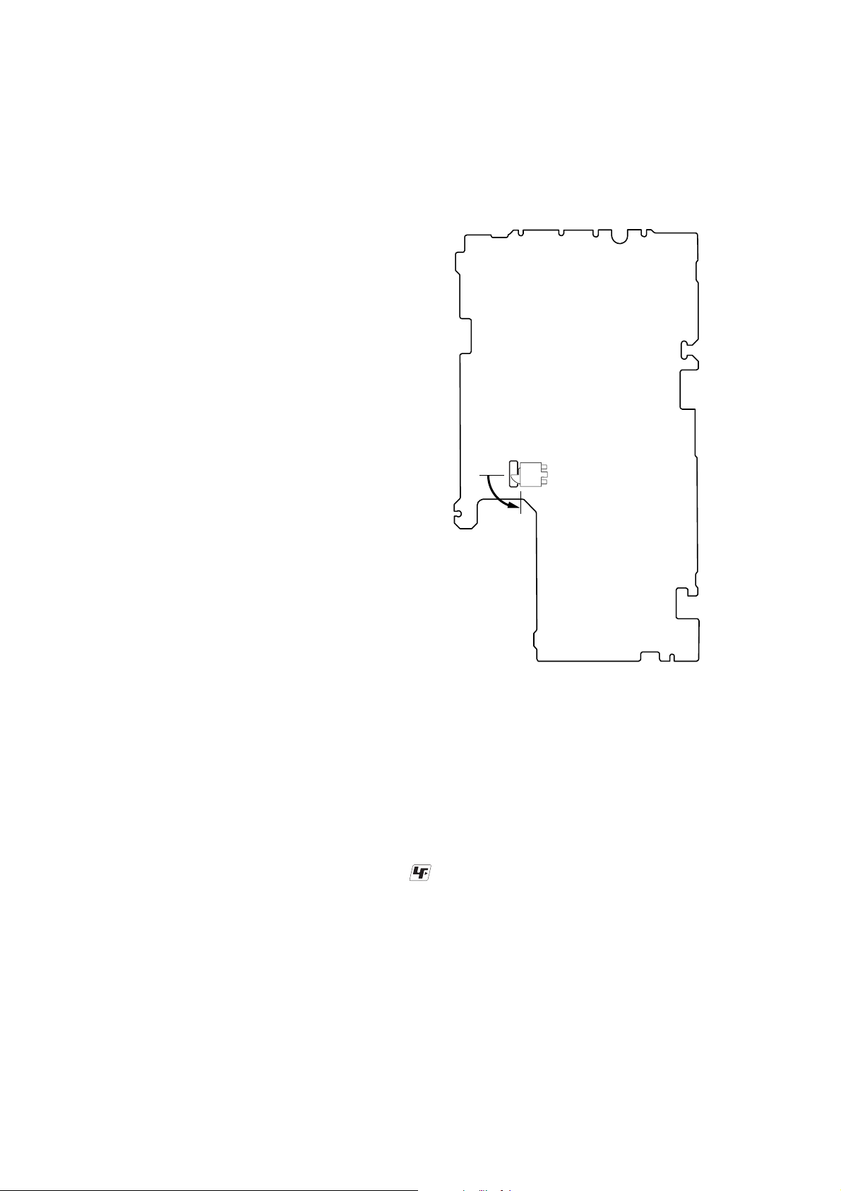
SECTION 1
SERVICING NOTES
In this set, the S102 (POWER) detects RECORD/PLAYBACK on.
It is mounted on the MAIN board, and therefore the RECORD/
PLA YB ACK on cannot be detected with the MAIN board remov ed.
When making an operation check and voltage check of mechanical
deck with the MAIN board removed, fix the S102 at turn on.
– MAIN BOARD (Component Side) –
7. EXPLODED VIEWS
7-1. Cabinet Section····························································· 13
7-2. Mechanism Deck Section-1 (MT-200DV-175)············· 14
7-3. Mechanism Deck Section-2 (MT-200DV-175)············· 15
8. ELECTRICAL PARTS LIST······································· 16
S102
on
UNLEADED SOLDER
Boards requiring use of unleaded solder are printed with the leadfree mark (LF) indicating the solder contains no lead.
(Caution: Some printed circuit boards may not come printed with
the lead free mark due to their particular size)
Notes on chip component replacement
•Never reuse a disconnected chip component.
• Notice that the minus side of a tantalum capacitor may be damaged by heat.
SAFETY-RELATED COMPONENT WARNING!!
COMPONENTS IDENTIFIED BY MARK 0 OR DOTTED
LINE WITH MARK 0 ON THE SCHEMATIC DIAGRAMS
AND IN THE PARTS LIST ARE CRITICAL TO SAFE
OPERATION. REPLACE THESE COMPONENTS WITH
SONY PARTS WHOSE PART NUMBERS APPEAR AS
SHOWN IN THIS MANUAL OR IN SUPPLEMENTS
PUBLISHED BY SONY.
2
: LEAD FREE MARK
Unleaded solder has the following characteristics.
• Unleaded solder melts at a temperature about 40 ˚C higher than
ordinary solder.
Ordinary soldering irons can be used but the iron tip has to be
applied to the solder joint for a slightly longer time.
Soldering irons using a temperature regulator should be set to
about 350 ˚C.
Caution: The printed pattern (copper foil) may peel away if the
heated tip is applied for too long, so be careful!
• Strong viscosity
Unleaded solder is more viscou-s (sticky, less prone to flow)
than ordinary solder so use caution not to let solder bridges occur such as on IC pins, etc.
• Usable with ordinary solder
It is best to use only unleaded solder but unleaded solder may
also be added to ordinary solder.
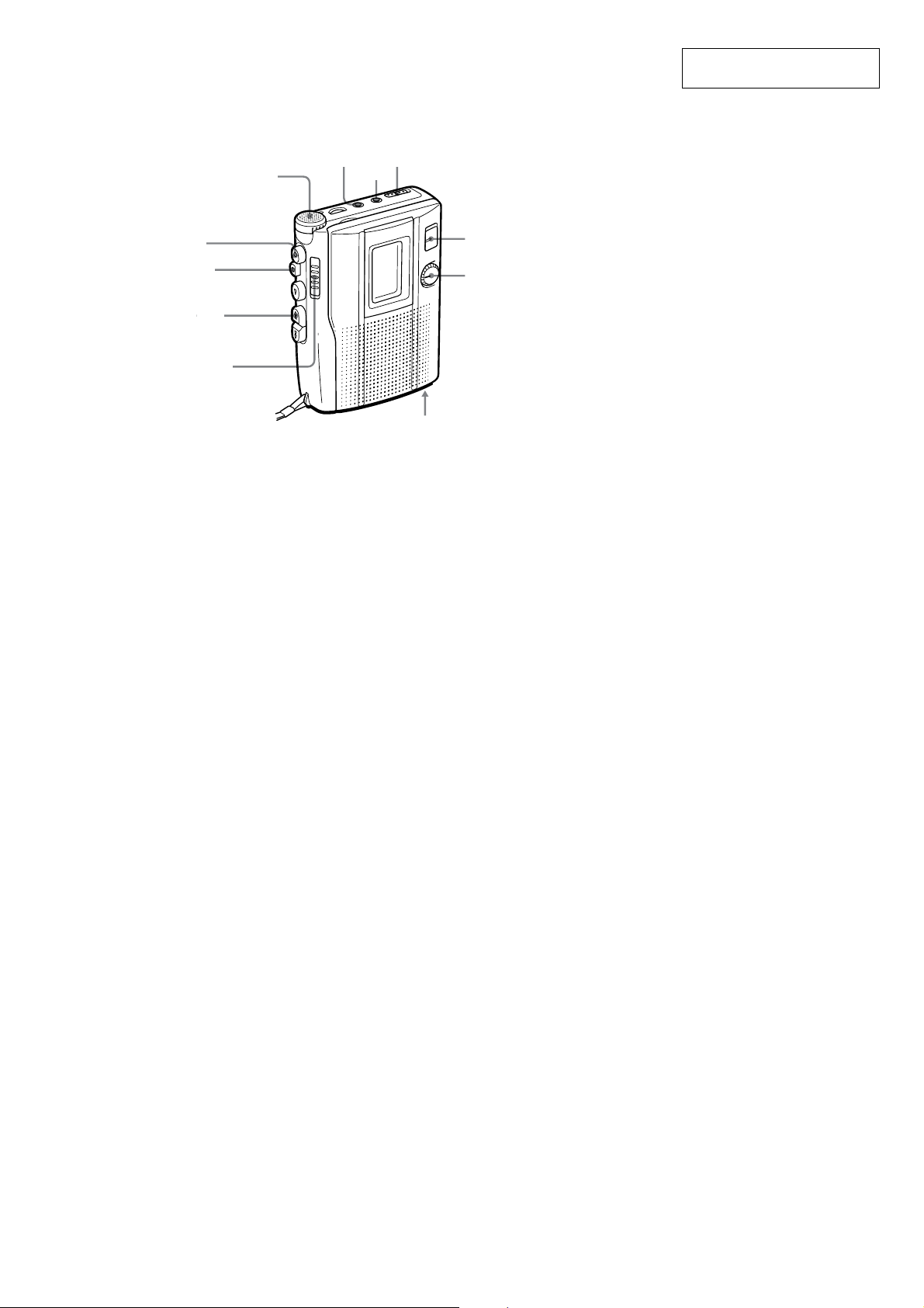
• LOCATION OF CONTROLS
SECTION 2
GENERAL
TCM-230DV
This section is extracted from
instruction manual.
MIC (PLUG IN POWER)
MIC (Built-in microphone,
Micrófono incorporado)
z REC
x STOP
m REW/
REVIEW
PAUSE .
EAR
VOR
DC IN 3V
REC TIME/
PLA Y MODE
SPEED CONTROL
3
TCM-230DV
• This set can be disassembled in the order shown below.
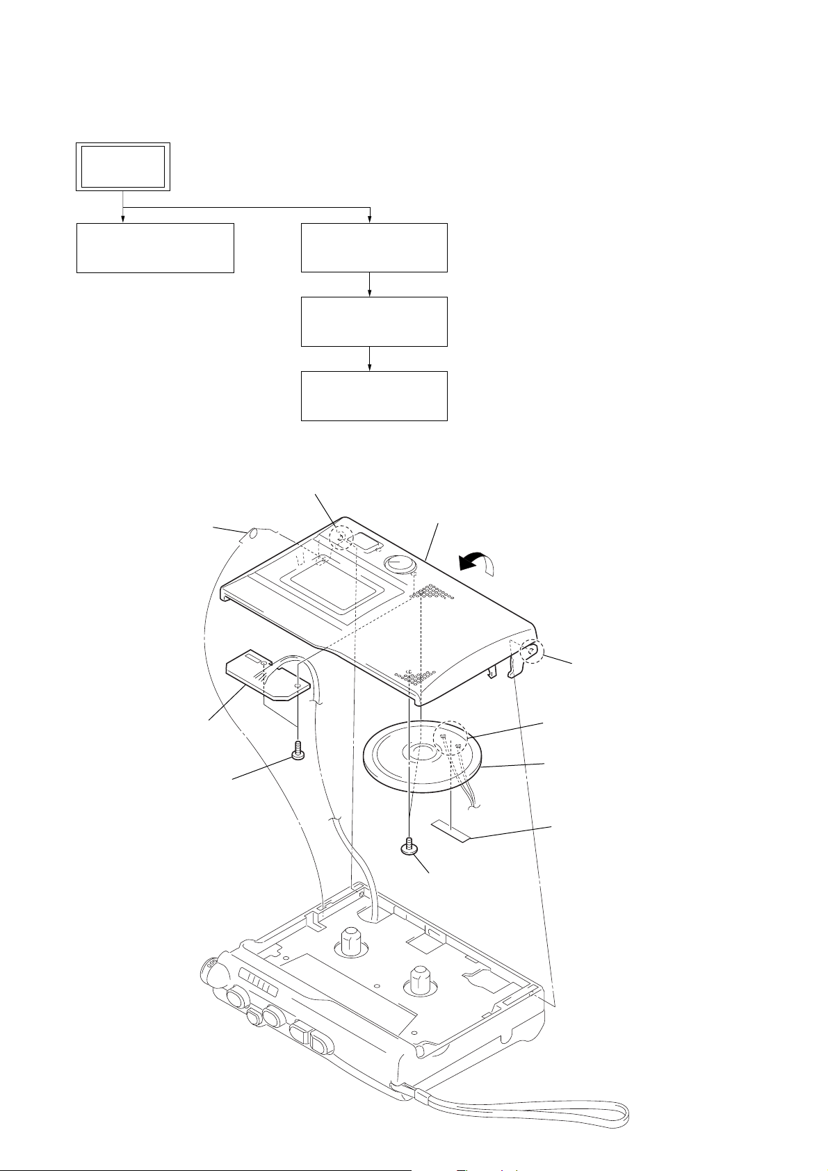
3-1. DISASSEMBLY FLOW
SET
SECTION 3
DISASSEMBLY
3-2. SPEAKER (SP901),
CASSETTE LID ASSY
(Page 4)
Note: Follow the disassembly procedure in the numerical order given.
3-3. CABINET (REAR)
(Page 5)
3-4. MAIN BOARD
(page 5)
3-5. MECHANISM DECK
(MT-200DV-175)
(Page 6)
3-2. SPEAKER (SP901), CASSETTE LID ASSY
2
boss
q;
spring (cassette)
qa
cassette lid assy
3
9
SW board
8
two
(TP 1.7)
screws
1
boss
5
6
two
screws
(TP B2.0)
Remove soldering
from the two points.
7
speaker (SP901)
4
cushion (B)
4
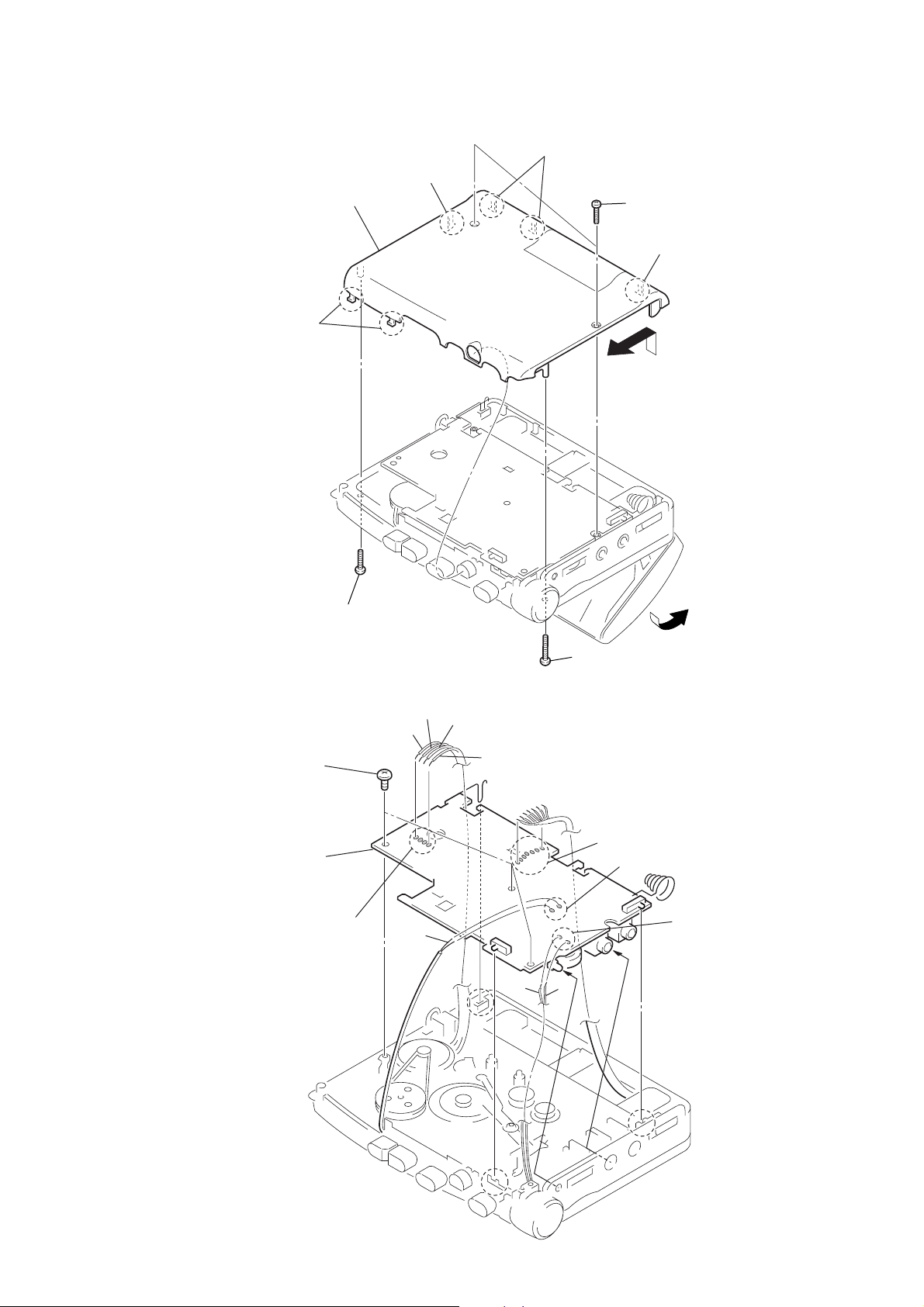
3-3. CABINET (REAR)
)
5
two
7
claws
cabinet (rear)
5
claw
5
two
claws
4
two
screws
(BTP 1.7
5
claw
6
TCM-230DV
× 9
3-4. MAIN BOARD
5
(M1.4 × 3)
2
Remove soldering from the four points.
three
6
MAIN board
screws
3
screw
(BTP 1.7
RED
× 9
WHT
)
BLK
WHT
ORG
BLK
RED
1
2
screw
(1.7
× 16
)
3
Remove soldering from the seven points.
1
Remove soldering from the two points.
4
Remove soldering
from the two points.
5
TCM-230DV
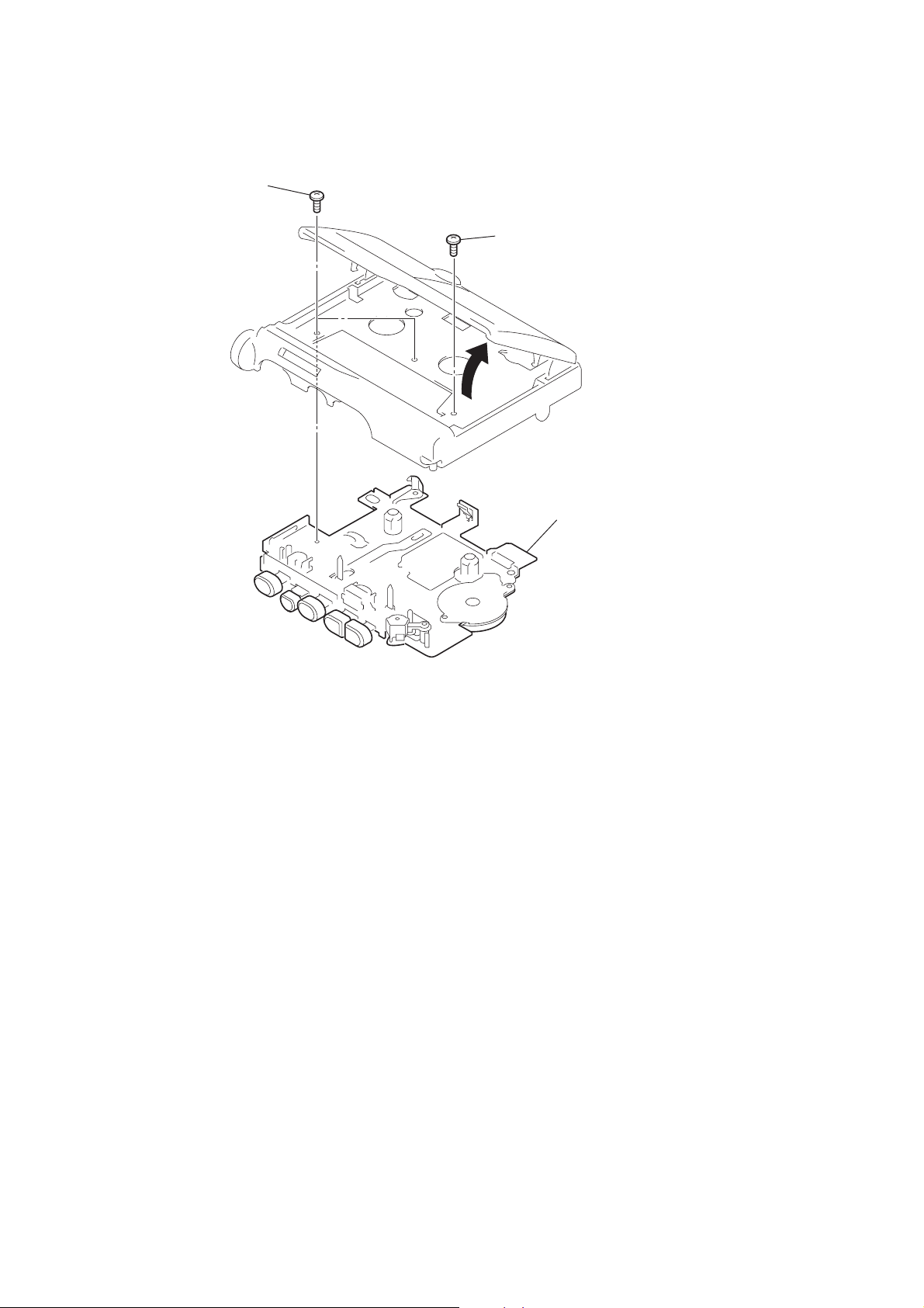
k
3-5. MECHANISM DECK (MT-200DV-175)
2
two
screws
(M1.4
×
2.2)
3
screw
(IB LOCK)
1
4
mechanism dec
(MT-200DV-175)
6
 Loading...