

Sony TCM-20DV, TCM-21DV, TCM-22DV, TCM-23DV Service Manual
TCM-20DV/21DV/
22DV/23DV
SERVICE MANUAL
Ver 1.1 2000. 11
With SUPPLEMENT-1
(9-927-668-81)
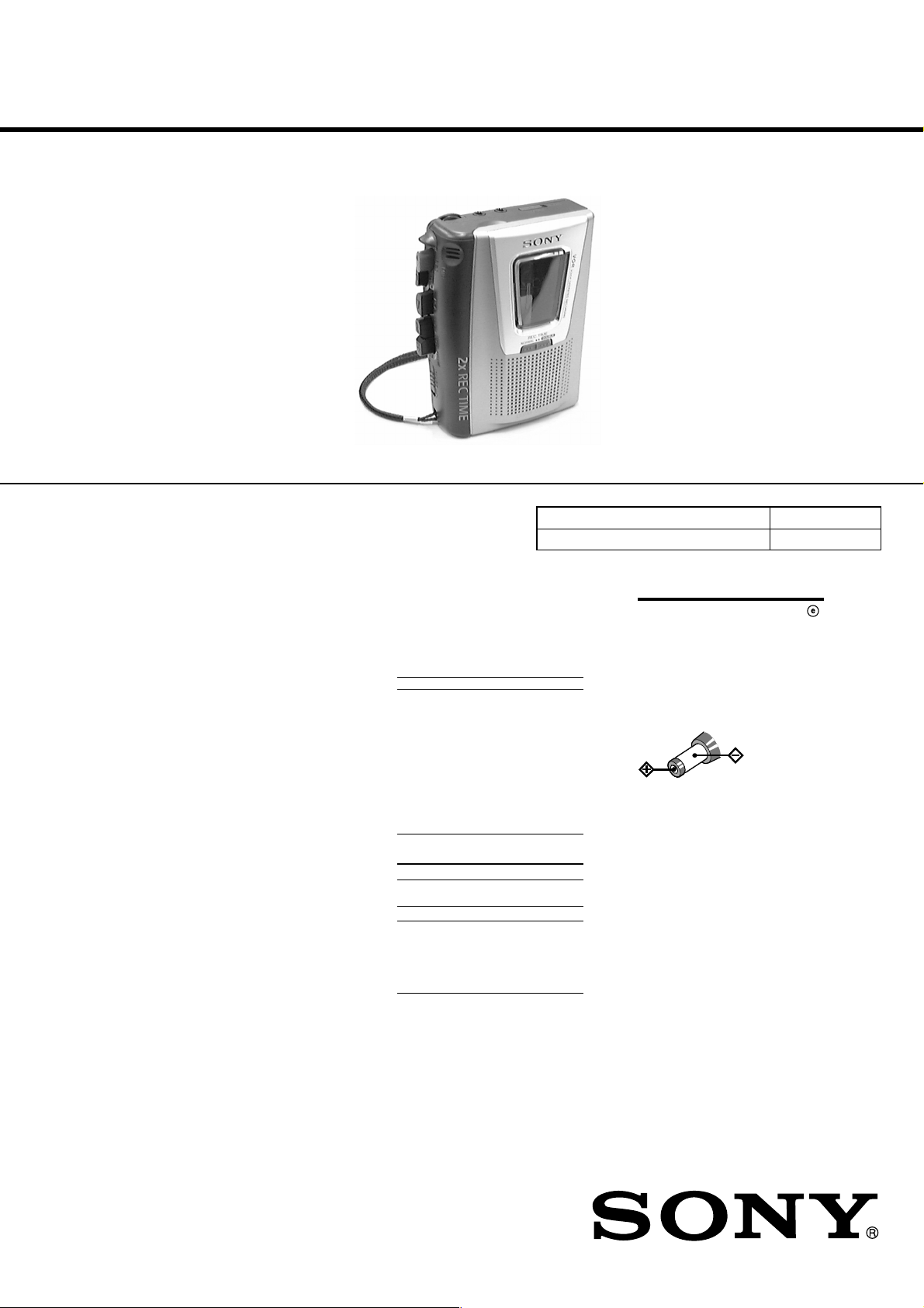
Photo: TCM-20DV
SPECIFICATIONS
Recording system
2-track 1 channel monaural
Tape speed
4.8 cm/s or 2.4 cm/s
Frequency range
250 - 6,300 Hz using nomal (TYPE
I) cassette (with REC TIME switch
at “NORMAL”)
Speaker
Approx. 3.6 cm (1
Power output
250 mW (at 10 % harmonic
distortion)
Input
Microphone input jack (minijack)
sensitivity 0.2 mV for 3 kilohms or
lower impedance microphone
Output
Earphone jack (minijack) for 8 - 300
ohms earphone
Variable range of the tape speed
From approx. +30% to –15% (with
REC TIME switch at “NORMAL”)
Power requirements
3 V DC batteries R6 (AA) × 2/
External DC 3 V power sources
Dimensions (w/h/d) (incl. projecting
parts and controls)
Approx. 112 × 36.6 × 90.3 mm
1
⁄2 × 1 1⁄2 x 3 5⁄8 in.)
(4
Mass
Approx. 175 g (6.2 oz.)
7
/16 in.) dia.
Supplied accessories
The instructions in this manual are for
4 models.
The TCM-20DV is the model used for
illustration purposes.
TCM- 23DV 22DV 21DV 20DV
AC power adaptor (1)
Battery charger adaptor (1)
Rechargeable batteries (2)
(NC-AA, 1.2V, 700mAh,
Ni-Cd)
Cassette tape C-90 (1)
Battery LR6 (2)
Monaural microphone (1)
Super-directional
microphone (1)
Carrying pouch (1)
Hand strap (1)
(attached to the unit)
Battery life
Sony alkaline
LR6 (SG)
Sony R6P (SR) 3 3
Sony
rechargeable
battery
(NC-AA) fully
charged (TCM22DV only)
* Measured value by the standard of
EIAJ (Electronic Industries
Association of Japan). (Using a Sony
HF series cassette tape and playing
back with speakers)
Note
The battery life may shorten
depending on the operation of the
unit.
For maximum performance we
recommend that you use alkaline
batteries.
(Approx. hours) (EIAJ*)
Playback Recording
11 11
Model Name Using Similar Mechanism NEW
Tape Transpor t Mechanism Type MT-20DV-118
— a ——
— a ——
— a ——
——a —
——a —
——a —
a ———
——a —
aaaa
33
US Model
TCM-20DV/21DV/22DV/23DV
Canadian Model
TCM-20DV/22DV
AEP Model
TCM-20DV/21DV
E Model
TCM-20DV/23DV
Chinese Model
TCM-20DV
House Current
Connect the AC power adaptor to
DC IN 3V and to a wall outlet. The
AC power adaptor is supplied only
with the TCM-22DV. For other
models, use the AC-E30HG AC
power adaptor (not supplied). Do
not use any other AC power
adaptor.
Note
Specifications for AC-E30HG vary for
each area. Check your local voltage
and the shape of the plug before
purchasing.
Design and specifications are subject
to change without notice.
(see Fig. A- )
Polarity of
the plug
CASSETTE-CORDER
SECTION 1
SERVICING NOTES
TABLE OF CONTENTS
1. SERVICING NOTES ............................................... 2
2. GENERAL ................................................................... 3
3. DISASSEMBLY ......................................................... 4
4. MECHANICAL ADJUSTMENTS....................... 7
5. ELECTRICAL ADJUSTMENTS......................... 8
6. DIAGRAMS
6-1. Block Diagram ................................................................ 9
6-2. Printed Wiring Board ...................................................... 11
6-3. Schematic Diagram ......................................................... 13
7. EXPLODED VIEWS ................................................ 16
8. ELECTRICAL PARTS LIST ............................... 19
In this set, the S102 (POWER) detects REC/PLAYBACK on.
It is mounted on the MAIN board, and therefore the REC/PLAYBACK on cannot be detected with the MAIN board removed.
When making an operation check and voltage check of mechanical deck with the MAIN board removed, fix the S102 at turn on.
– MAIN BOARD (Conductor Side) –
S102
on
SAFETY-RELATED COMPONENT WARNING!!
COMPONENTS IDENTIFIED BY MARK 0 OR DOTTED
LINE WITH MARK 0 ON THE SCHEMA TIC DIA GRAMS
AND IN THE PARTS LIST ARE CRITICAL TO SAFE
OPERATION. REPLACE THESE COMPONENTS WITH
SONY PARTS WHOSE PART NUMBERS APPEAR AS
SHOWN IN THIS MANUAL OR IN SUPPLEMENTS PUBLISHED BY SONY.
ATTENTION AU COMPOSANT AYANT RAPPORT
À LA SÉCURITÉ!
LES COMPOSANTS IDENTIFIÉS P AR UNE MARQUE 0
SUR LES DIAGRAMMES SCHÉMATIQUES ET LA LISTE
DES PIÈCES SONT CRITIQUES POUR LA SÉCURITÉ
DE FONCTIONNEMENT. NE REMPLACER CES COMPOSANTS QUE PAR DES PIÈCES SONY DONT LES
NUMÉROS SONT DONNÉS DANS CE MANUEL OU
DANS LES SUPPLÉMENTS PUBLIÉS PAR SONY.
Flexible Circuit Board Repairing
• Keep the temperature of the soldering iron around 270 ˚C during repairing.
• Do not touch the soldering iron on the same conductor of the
circuit board (within 3 times).
• Be careful not to apply force on the conductor when soldering
or unsoldering.
Notes on chip component replacement
• Never reuse a disconnected chip component.
• Notice that the minus side of a tantalum capacitor may be damaged by heat.
– 2 –
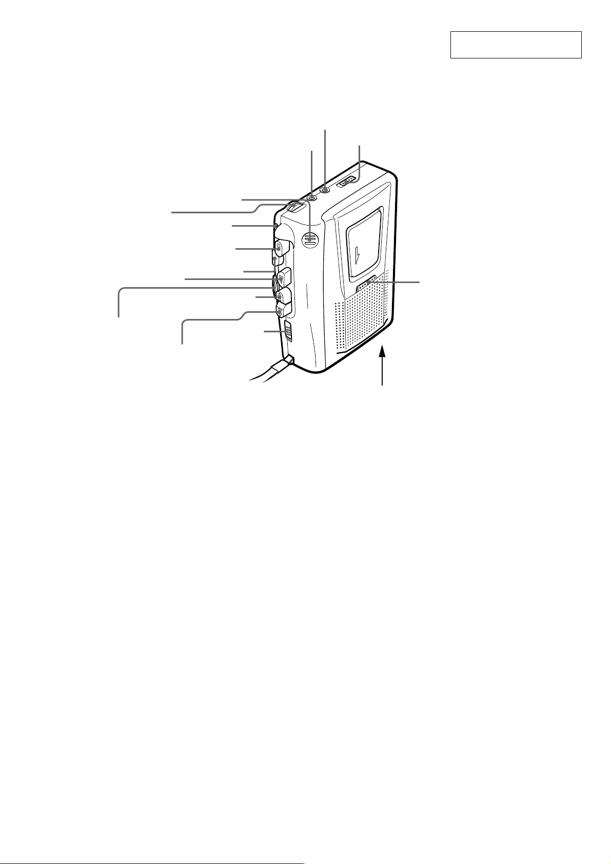
• Location of Controls
VOL
Built-in mic
BATT
z REC
SECTION 2
GENERAL
EAR
MIC
VOR
This section is extracted from
instruction manual.
B PLAY
SPEED CONTROL
M FF/CUE
x STOP
m REW/
REVIEW
PAUSE
.
REC TIME
DC IN 3 V
– 3 –
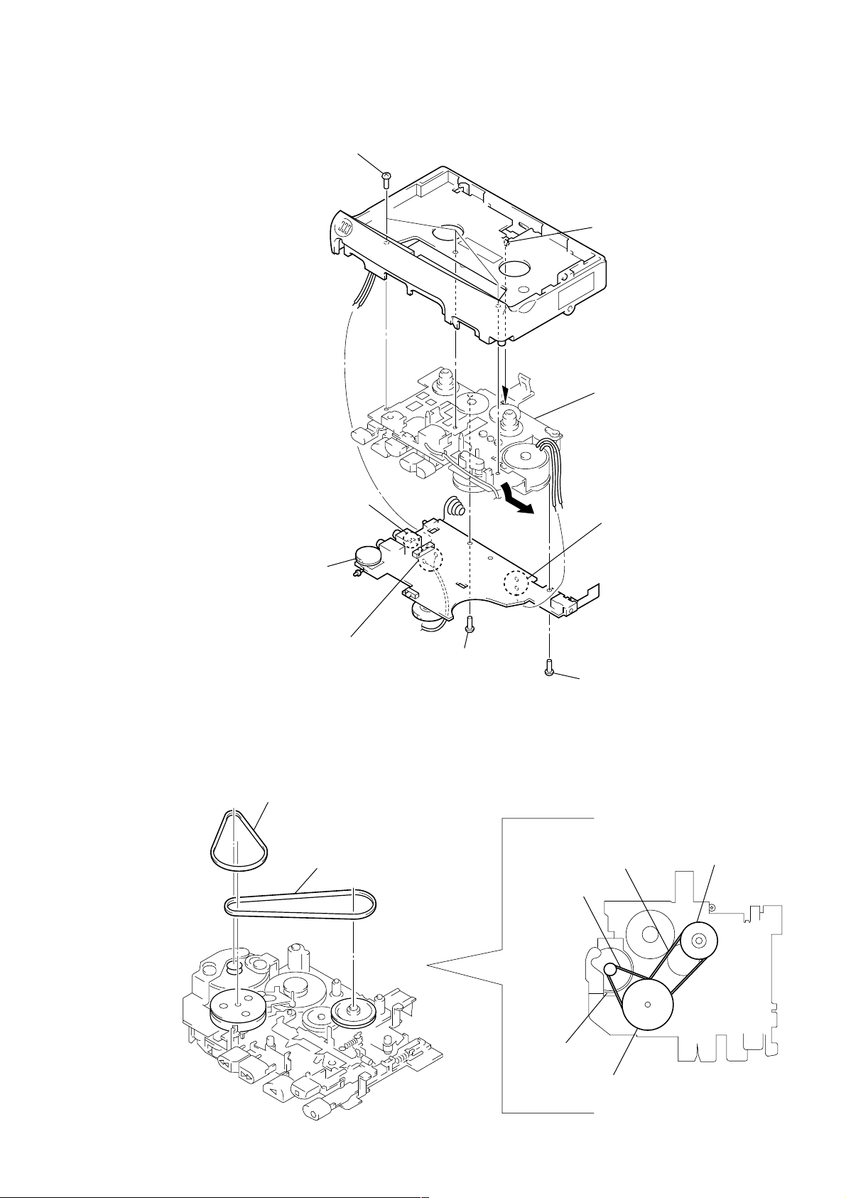
• This set can be disassembled in the order shown below.
T
G
SECTION 3
DISASSEMBLY
SET
Note: Follow the disassembly procedure in the numerical order given.
CABINET (REAR), CASSETTE LID
CABINET (REAR), CASSETTE LID
9 cassette lid
7 boss
MAIN BOARD, MECHANISM DECK (MT-20DV-118)
INSTALLATION CASSETTE SPRIN
cabinet front
cassette spring
BEL
cassette lid
3 four claws
2 screw
(IB lock)
7 boss
6 Remove the six solders.
5 hand strap
4 cabinet (rear)
3 claw
1 three screws
(B1.7 × 9)
– 4 –
MAIN BOARD, MECHANISM DECK (MT-20DV-118)
5 three screws
(IB lock)
1 Remove the two solders
electret condenser microphone
(MIC101).
6 claw
7 mechanism deck
(MT-20DV-118)
1 Remove the two solders
motor (M901).
BELT
4 MAIN board
1 Remove the two solders
magnetic head (HRP901).
1 belt (capstan)
2 belt (FR)
3 screw
(M1.4)
2 screw
(1.7)
capstan belt
FR belt
pulley (FR) assy
– 5 –
motor DC
flywheel assy
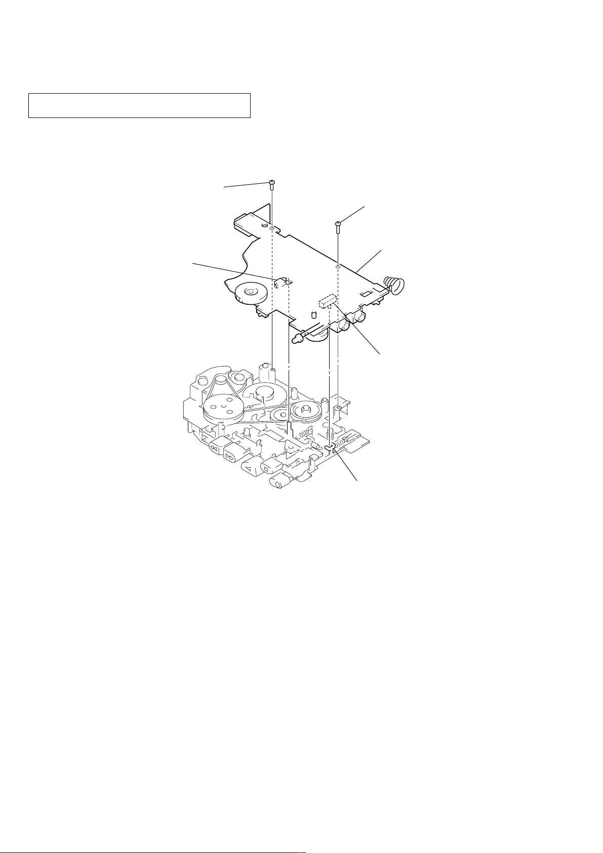
INSTALLATION MAIN BOARD
On installation MAIN board, adjust to the S101 and
the S102.
screw
(1.7)
S102
(POWER)
screw
(M1.4)
MAIN board
S101 (REC/PB)
lever (REC)
– 6 –
SECTION 4
MECHANICAL ADJUSTMENTS
1. Clean the following parts with a denatured-alcohol-moistened
swab:
record/playback head pinch roller
erase head rubber belt
capstan idlers
2. Demagnetize the record/playback head with a head demagnetizer. (Do not bring the head demagnetizer close to the erase
head.)
3. Do not use a magnetized screwdriver for the adjustments.
4. After the adjustments, apply suitable locking compound to the
parts adjusted.
5. The adjustments should be performed with the rated power
supply voltage (2.5 V) unless otherwise noted.
Torque Measurement
Mode Torque Meter Meter Reading
FWD
CQ-102C
FWD
Back Tension
FF
REW (more than 0.69 oz•inch)
CQ-201B (more than 50 g•cm)
2.16 - 4.7 mN•m
(22 - 48 g•cm)
(0.31 - 0.67 oz•inch)
0.05 - 0.29 mN•m
(0.5 - 3 g•cm)
(0.007 - 0.04 oz•inch)
4.90 mN•m
T ape Tension Measurement
Mode Torque Meter Meter Reading
FWD CQ-403C (more than 50 g)
4.90 mN•m
(more than 1.76 oz)
– 7 –
 Loading...