

Sony TCKE-240, TCRE-240, TCRE-340 Service manual
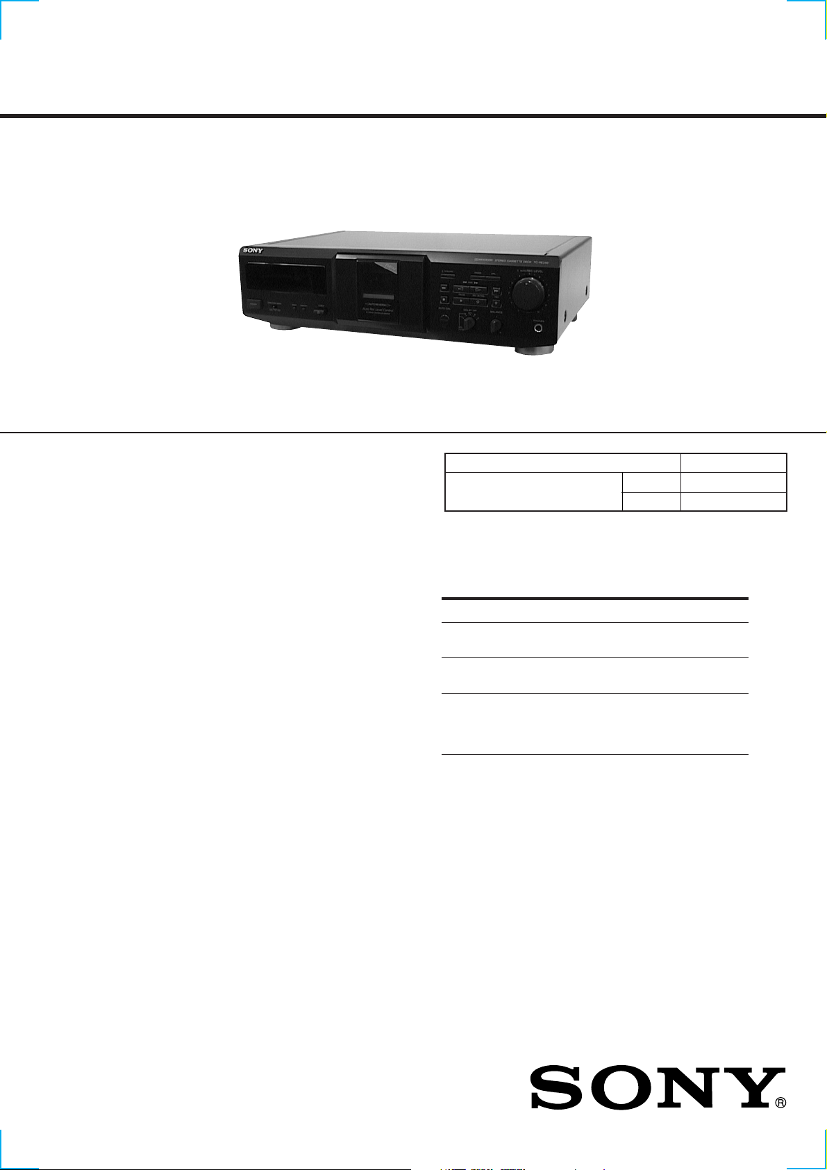
TC-KE240/RE340
SERVICE MANUAL
Photo: TC-RE340 (Black type)
Dolby noise reduction and HX Pro headroom extension manufactured under license from Dolby
Laboratories Licensing Corporation.
HX Pro originated by Bang & Olufsen.
“DOLBY”, the double-D symbol ;, and “HX PRO”
are trademarks of Dolby Laboratories Licensing Corporation.
SPECIFICATIONS
AEP Model
TC-KE240/RE340
UK Model
E Model
Australian Model
Model Name Using Similar Mechanism NEW
T ape Transport Mechanism Type
KE240 TCM-230ASV1
RE340 TCM-230ASR4N
TC-KE240
TC-RE340
System
Recording system
4-track 2-channel stereo
Fast-winding time (approx.)
100 sec. (with Sony C-60 cassette)
Bias
AC bias
Signal-to-noise ratio (at peak level and weighted with Dolby
NR off)
Type I tape, Sony Type I (NORMAL): 55 dB
Type II tape, Sony Type II (HIGH): 57 dB
Type IV tape, Sony Type IV (METAL): 58 dB
S/N ratio improvement (approximate values)
With Dolby B NR on: 5 dB at 1 kHz, 10 dB at 5 kHz
With Dolby C NR on: 15 dB at 500 Hz, 20 dB at 1 kHz
Harmonic distortion
0.4% (with Type I tape, Sony Type I (NORMAL):
160 nWb/m 315 Hz, 3rd H.D.)
1.8% (with Type IV tape, Sony Type IV (METAL):
250 nWb/m 315 Hz, 3rd H.D.)
Frequency response (Dolby NR off)
Tape type
Type I tape, Sony Type I
(NORMAL)
Type II tape, Sony Type II
(HIGH)
Type IV tape, Sony Type IV
(METAL)
Inputs
Line inputs (phono jacks)
Sensitivity: 0.16 V
Input impedance: 47 kilohms
30 – 15,000 Hz (±3 dB, IEC),
20 – 16,000 Hz (±6 dB)
30 – 16,000 Hz (±3 dB, IEC),
20 – 17,000 Hz (±6 dB)
30 – 18,000 Hz (±3 dB, IEC),
20 – 19,000 Hz (±6 dB),
30 – 13,000 Hz (±3 dB, –4 dB
recording)
– Continued on next page –
STEREO CASSETTE DECK

Outputs
Line outputs (phono jacks)
Rated output level: 0.5 V at a load impedance of
47 kilohms
Load impedance: Over 10 kilohms
Headphones (stereo phone jack)
Output level: 0.25 mW at a load impedance of
32 ohms
General
Power requirements
Europe and certain countries in Asia: 220 – 230 V AC, 50/
60 Hz
Australia: 240 V AC, 50/60 Hz
Other countries: 110 – 120/220 – 240 V AC, 50/60 Hz
Power consumption
TC-RE340: 15 W
TC-KE240: 14 W
Dimensions (approx.) (w/h/d)
430 × 120 × 290 mm
Mass (approx.)
3.3 kg
Notes on chip component replacement
• Never reuse a disconnected chip component.
• Notice that the minus side of a tantalum capacitor may be damaged by heat.
Supplied accessories
Audio connecting cords (2)
Design and specifications are subject to change without notice.
SAFETY-RELATED COMPONENT WARNING!!
COMPONENTS IDENTIFIED BY MARK 0 OR DOTTED
LINE WITH MARK 0 ON THE SCHEMATIC DIA GRAMS
AND IN THE PARTS LIST ARE CRITICAL TO SAFE
OPERATION. REPLACE THESE COMPONENTS WITH
SONY PARTS WHOSE PART NUMBERS APPEAR AS
SHOWN IN THIS MANU AL OR IN SUPPLEMENTS PUBLISHED BY SONY.
2
SECTION 1
SERVICING NOTE
TABLE OF CONTENTS
1. SERVICING NOTE.................................................. 3
2. GENERAL ................................................................... 4
3. DISASSEMBLY ......................................................... 5
4. MECHANICAL ADJUSTMENTS....................... 10
5. SERVICE MODE...................................................... 11
6. ELECTRICAL ADJUSTMENTS......................... 12
7. DIAGRAMS
7-1. Note for Printed Wiring Boards and
Schematic Diagrams ....................................................... 15
7-2. Printed Wiring Boards – HEAD RELAY (REC/PB)/
LEAF SW (REC/PB) Boards –....................................... 18
7-3. Printed Wiring Board – MAIN Board – ........................ 19
7-4. Schematic Diagram – MAIN Section (1/2) –................ 20
7-5. Schematic Diagram – MAIN Section (2/2) –................ 21
7-6. Printed Wiring Boards
– TRANS/POWER SW Boards – ................................... 22
7-7. Schematic Diagram
– TRANS/POWER SW Boards – ................................... 23
7-8. Printed Wiring Board – DISPLAY Board – .................. 24
7-9. Schematic Diagram – DISPLAY Board – ..................... 25
7-10. Printed Wiring Boards – KEY/HP Boards – ................. 26
7-11. Schematic Diagram – KEY Board – ............................. 26
7-12. IC Pin Function Description ........................................... 28
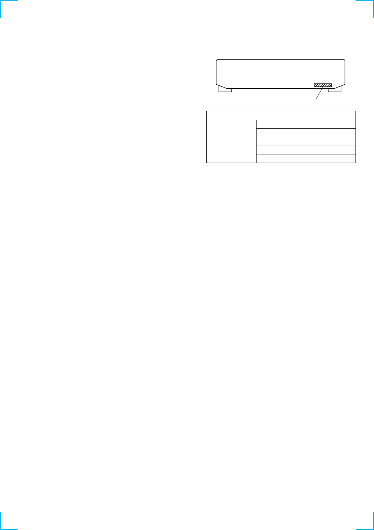
MODEL IDENTIFICATION
– BACK PANEL –
Part No.
Model Part No.
TC-KE240
TC-RE340 Australian model 3-042-490-1s
AEP model 3-042-502-0s
UK model 3-042-502-1s
AEP model 3-042-490-0s
Singapore model 3-042-490-2s
8. EXPLODED VIEWS................................................ 30
9. ELECTRICAL PARTS LIST ............................... 33
3
1
234 8065 7 9
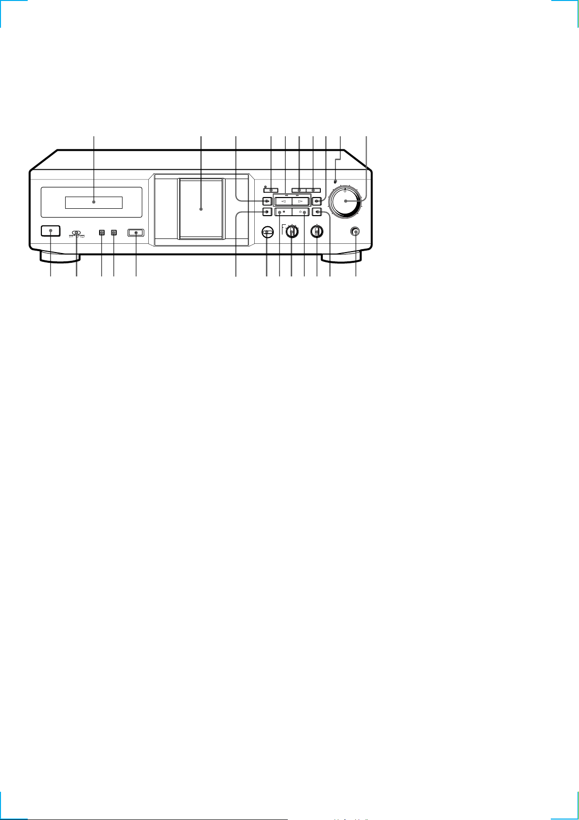
• LOCATION OF CONTROLS
– Front Panel –
POWER
DIRECTION MODE
RESET MEMORY
EJECT
qa qd qf qg qk w;qj ql wa wdqh wsqs
SECTION 2
GENERAL
FADER ARL
SYNCHRO
AMS
REC MUTING RECPAUSE
AUTO CAL
DOLBY NR
OFF
B
B
CC
MPX
FILTER
BALANCE
L R
REC LEVEL
AUTO
5
6
4
3
2
1
7
8
9
0
10
PHONES
1 Fluorescent indicator tube
2 Cassette holder
3 m button
4 SYNCHRO button and indicator
5 H button (TC-KE240)
h, H buttons (TC-KE340)
6 FADER button
7 ARL button
8 M button
9 AUTO REC LEVEL indicator
0 RED LEVEL knob
qa POWER button
qs DIRECTION MODE button
qd RESET button
qf MEMORY button
qg EJECT button
qh x button
qj AUTO CAL button (TC-RE340)
qk X button
ql DOLBY NR knob
w; W button
wa BALANCE knob
ws z button
wd PHONES jack
4
)
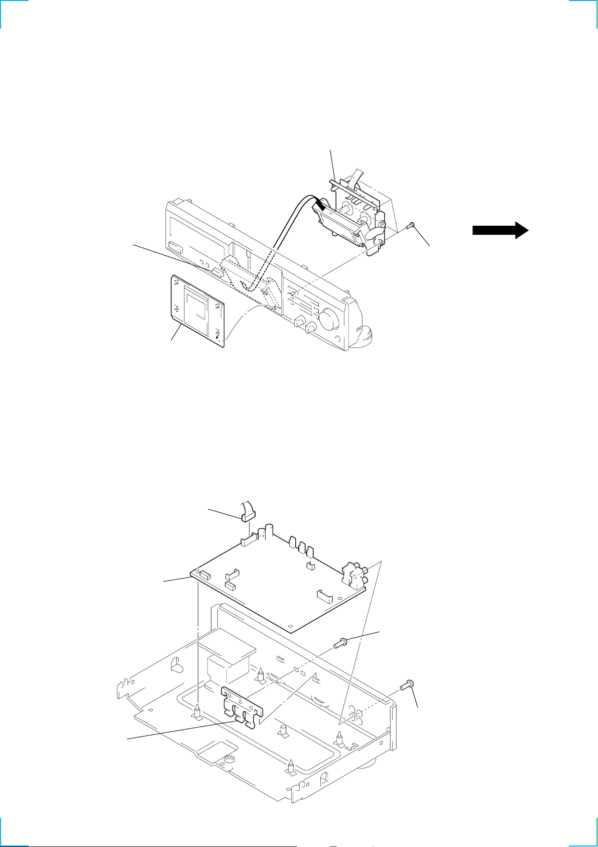
SECTION 3
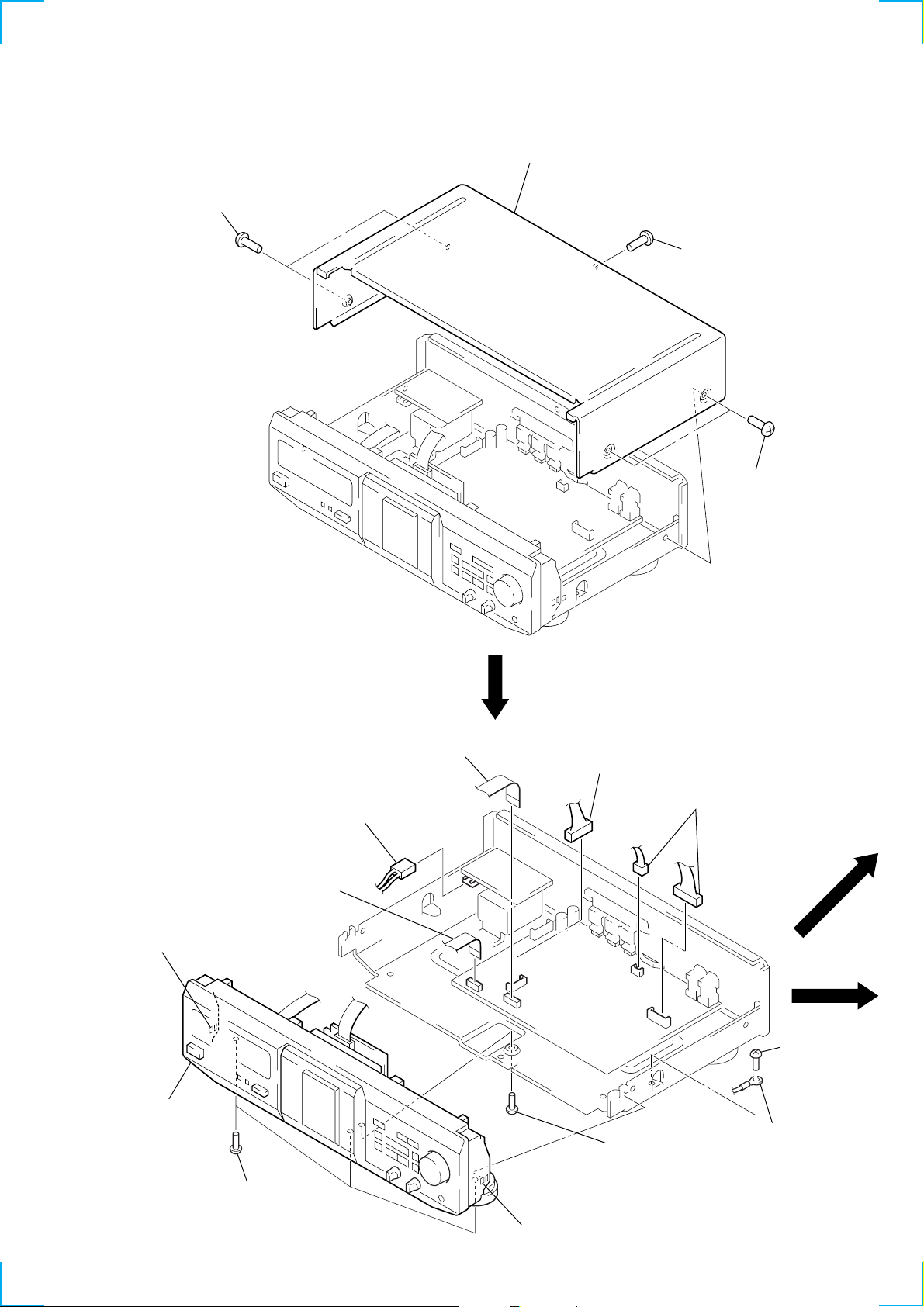
DISASSEMBLY
Note: Follow the disassembly procedure in the numerical order given.
CASE (410726)
1
two screws
(case 3 TP 2)
3
case (410726)
2
screw (BVTT3 × 6)
1
two screws
(case 3 TP 2)
FRONT PANEL SECTION
1
wire (flat type)
(CN801)
6
claw
7
front panel
section
5
three screws
(BVTP3
2
connector
(CN702)
×
8)
1
wire (flat type)
(CN302)
2
connector
(CN802)
5
screw
(BVTT3
2
two connectors
(CN301, CN803)
×
6)
3
screw
×
(BVTT3
4
harness
6
6
claw
5
MECHANISM DECK
)
(TCM-230ASV1: KE240)
(TCM-230ASR4N: RE340)
1
Push the button (eject).
2
lid (cassette) ass’y
4
mechanism deck
(TCM-230ASV1: KE240)
(TCM-230ASR4N: RE340)
3
four screws
(BVTP2.6
×
8)
MAIN BOARD
3
bracket (TR)
5
main board
1
connector
(CN701)
2
screw (BVTP3 × 8)
4
screw (BVTP3 × 8
6
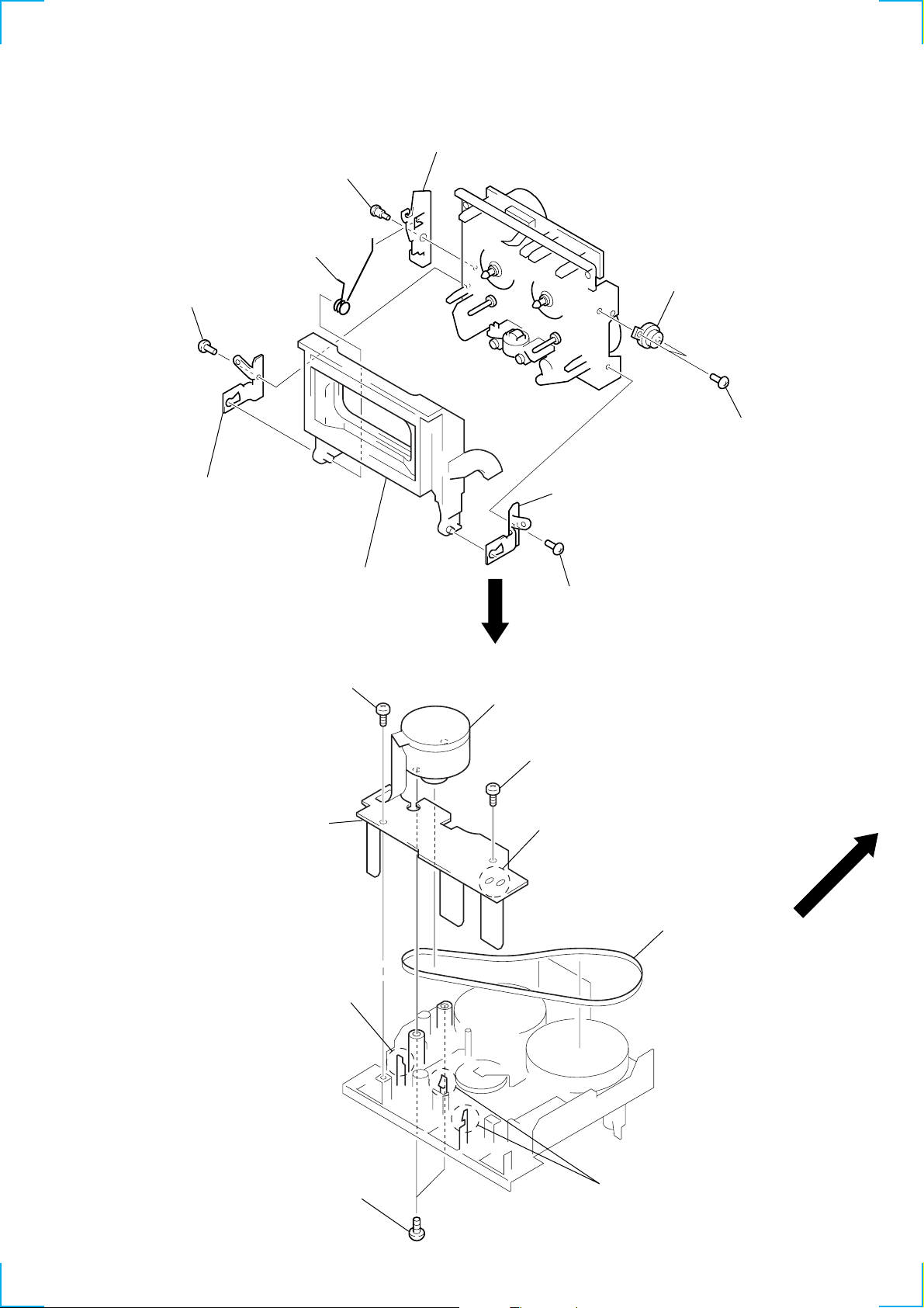
CASSETTE HOLDER (L) ASS’Y
1
step screw
7
loading spring (L)
3
screw (BVTT2 × 4)
4
fulcrum plate (L)
2
lever (LOCK L)
6
fulcrum plate (R)
q;
damper
9
two screws
(BVTT2
×
5)
8
cassette holder (L) ass’y
CAPSTAN MOTOR ASS’Y, LEAF SW BOARD
4
screw
(PS2.6 × 6)
6
leaf SW board
5
claw
5
screw (BVTT2 × 4)
3
capstan motor ass’y (M1002)
4
screw (PS2.6 × 6)
1
two solders
7
belt (capstan)
2
two screws
(PS2.6 × 6)
5
two claws
7
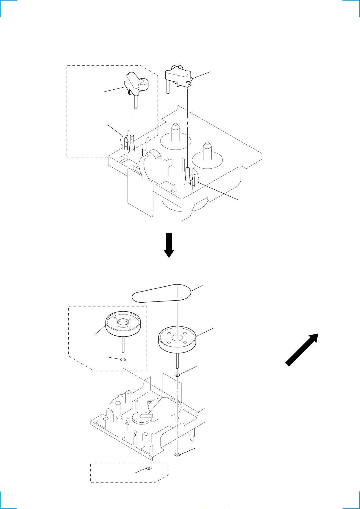
PINCH LEVER ASS’Y
y
RE340
4
pinch lever
(REV) ass’y
3
claw
2
pinch lever (FWD) ass’
1
claw
FLYWHEEL ASS’Y
RE340
6
flywheel (REV)
ass’y
7
washer
1
belt (FR2)
3
4
washer
2
stopper washer
flywheel (FWD) ass’y
RE340
5
stopper washer
8
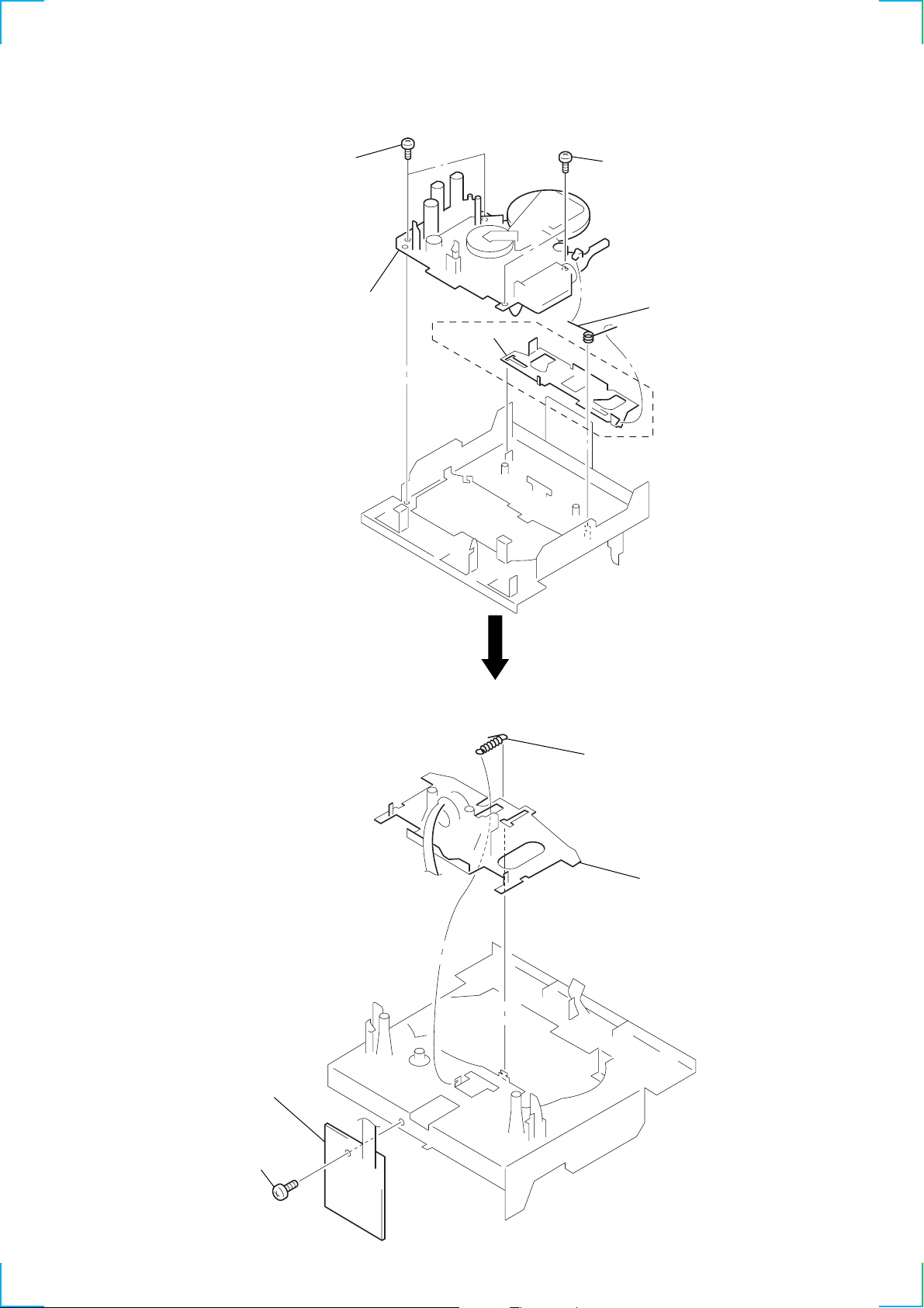
MECHANICAL BLOCK ASS’Y (AMS)
g
2
two screws
(BVTT2
×
3.5)
3
mechanical block ass’y
(AMS)
4
reverse
slider
2
two screws
(BVTT2
×
3.5)
1
torsion sprin
RE340
HEAD BASE ASS’Y (KE240), HEAD DECK ASS’Y (RE340),
HEAD RELAY BOARD
2
head relay (REC/PB)
board
3
tension spring (HEAD)
4
head base ass’y (KE240),
head deck ass’y (RE340)
1
screw (BVTT2 × 4)
9

SECTION 4
MECHANICAL ADJUSTMENTS
1. Clean the following parts with a denatured-alcohol-moistened
swab:
record/playback/erase head pinch roller
rubber belt capstan
idler
2. Demagnetize the playback head with a head demagnetizer.
3. Do not use a magnetized screwdriver for the adjustments.
4. After the adjustments, apply suitable locking compound to the
parts adjusted.
5. The adjustments should be performed with the power supply
voltage unless otherwise noted.
• Tor que Measurement
Mode Torque Meter Meter Reading
Forward CQ-102C (28 – 69 g•cm)
Forward
Back Tension
Reverse CQ-102RC (30 – 69 g•cm)
Reverse
Back Tension
FF, REW CQ-201B (70 – 159 g•cm)
CQ-102C (1.1 – 6.0 g•cm)
CQ-102RC (1.1 – 6.0 g•cm)
2.74 – 6.86 mN•m
(0.42 – 0.90 oz•inch)
0.1 – 0.59 mN•m
(0.01 – 0.06 oz•inch)
2.74 – 6.86 mN•m
(0.42 – 0.90 oz•inch)
0.1 – 0.59 mN•m
(0.01 – 0.06 oz•inch)
6.86 – 15.68 mN•m
(0.83 – 2.78 oz•inch)
10
SECTION 5
dB
–20 –10 –4 0 +2 +4 +6 +8–30
–
∞
L
R
;
figure 1
TAPE TYPE
dB
–20 –10 –4 0 +2 +4 +6 +8–30
–
∞
L
R
PLAY
REC
DOLBY NR
M
AUTO
CAL
I II IV
B C
88 88
;
figure 4
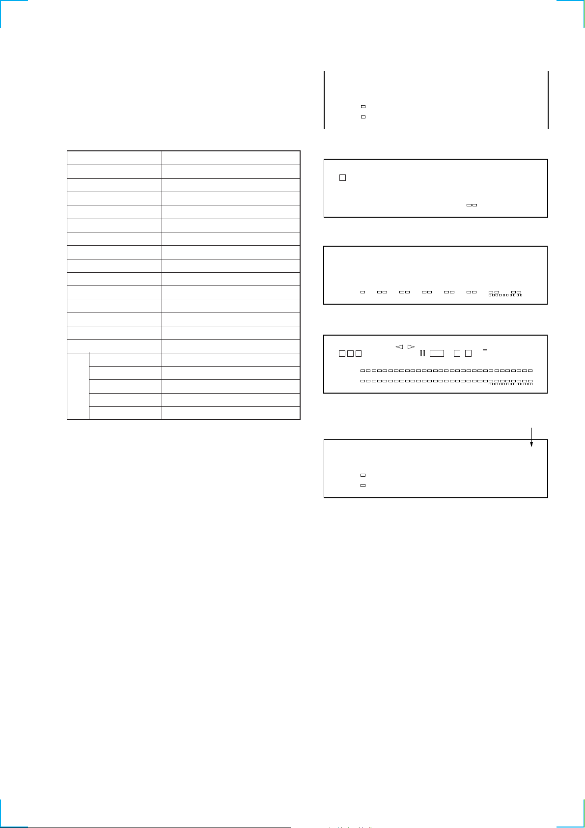
SERVICE MODE
Key Check & Display Check Mode
1. While pressing two buttons of [SYNCHRO] and
[REC MUTING ], press the [POWER] button to turn the
power ON.
2. Enter the test mode and display as figure 1.
3. Each time some button is pressed or switch position is selected,
the fluorescent indicator tube displays as following table.
Button or Switch Display
RESET refer to figure 2
MEMORY refer to figure 3
SYNCHRO all segments (refer to figure 4)
FADER 0 (refer to figure 5)
ARL 1
m 2
h *1 3
H 4
M 5
x 6
PAUSE X 7
REC MUTING W 8
REC z 9
AUTO CAL *1 A
MPX FILTER C DOLBY NR [C]
MPX FILTER B DOLBY NR [B]
OFF no indication
C [C]
Dolby NR
switch
B [B]
*1) TC-RE340 only
W
I
–
–20 –10 –4 0 +2 +4 +6 +8–30
∞
dB
L
R
;
8
figure 2
–
–20 –10 –4 0 +2 +4 +6 +8–30
∞
dB
L
R
;
figure 3
number indication
0
–
–20 –10 –4 0 +2 +4 +6 +8–30
∞
dB
L
R
;
figure 5
11
SECTION 6
e
ELECTRICAL ADJUSTMENTS
Note: The adjustments should be performed in the order given in the ser-
vice manual. As a rule, adjustments about playback should be performed before those about recording.
The adjustments should be performed for both L-CH and R-CH.
• Switches and controls should be set as follows unless otherwise
specified.
DOLBY NR, MPX FILTER switch: OFF
DIRECTION MODE switch: g
• Standard Record:
Deliver the standard input signal level to the input jack and set
the [REC LEVEL] volume to obtain the standard output signal
level as follows.
– Record Mode –
J301
AF OSC
attenuator
600
LINE IN
10 k
Ω
jack
Ω
LINE OUT
set
jack
47 k
level meter
Ω
+
–
0 dB=0.775 V
Standard Input Level
input terminal LINE IN
source impedance 10 kΩ
input signal level 0.5 V (–3.8 dB)
Standard Output Level
output terminal LINE OUT
load impedance 47 kΩ
output signal level 0.5 V (–3.8 dB)
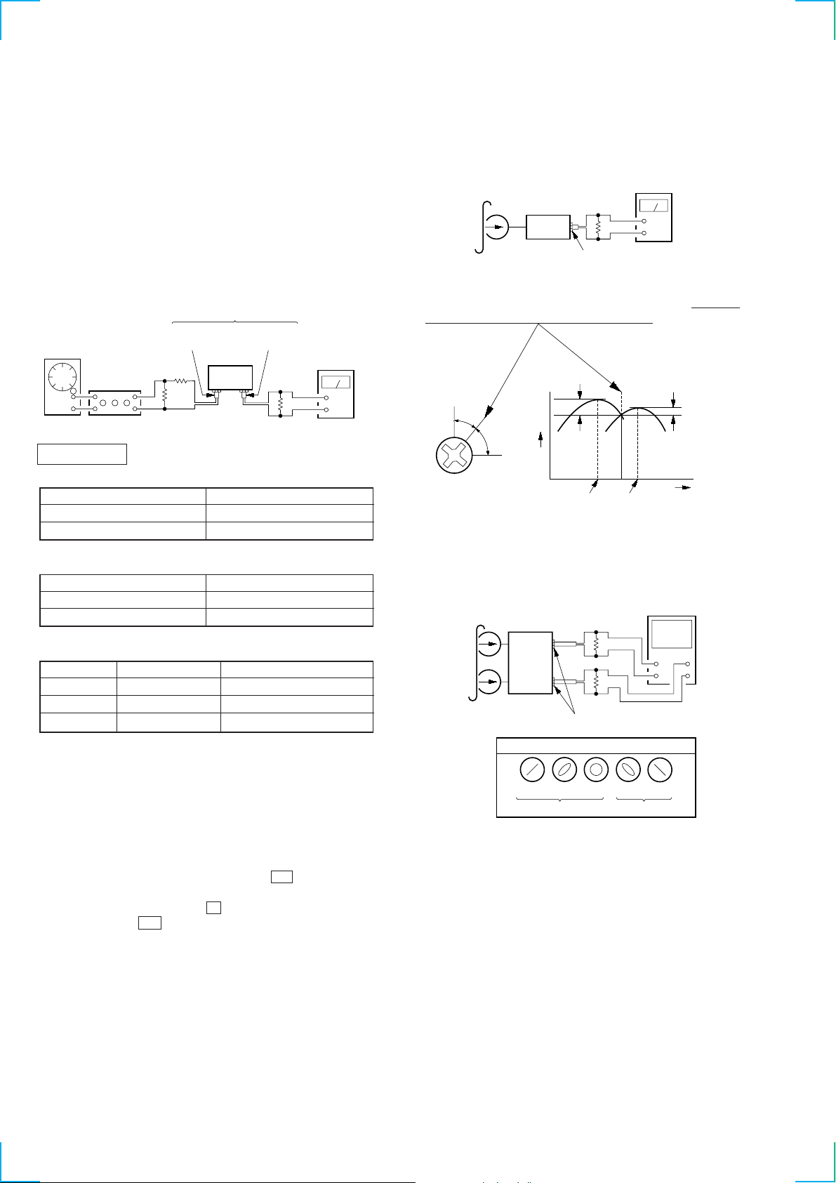
Record/Playback Head Azimuth Adjustment
Procedure:
1. Mode: FWD playback
Test tape
P-4-A100
(10 kHz, –10 dB)
47 k
set
level meter
Ω
+
–
LINE OUT jack (J301)
2. Turn the adjustment screw for the maximum output levels. If
these levels do not match, turn the adjustment screw until both
of output levels match together within 1 dB.
output
level
within
1dB
L-CH peak
within
1dB
angl
R-CH peak
L-CH
peak
Screw
position
R-CH
peak
3. Phase Check
Mode: playback
test tape
P-4-A100
(10 kHz, –10 dB)
L-CH
47 k
oscilloscope
Ω
Test T ape
Ty pe Signal Used for
P-4-A100 10 kHz, –10 dB Azimuth Adjustment
P-4-L300 315 Hz, 0 dB Playback Level Adjustment
WS-48B 3 kHz, 0 dB Tape Speed Adjustment
Test Mode
1. While pressing two buttons of [ARL] and [REC MUTING ],
W
press the [POWER] button to turn the power on.
2. All segments of the fluorescent indicator tube are light up for
about one second, and the test mode is set.
The test mode has a special function as bellow.
• Counter RESET & MEMORY Function
(1) Press the [RESET] button to reset the counter.
(2) Press the [REC ] button then the H button to starts
z
recording.
(3) After record, press the x button to stop recording.
(4) Press the m button to rewind the tape.
(5) Rewinding tape is automatically stopped at the point
where recording was started.
3. To release the test mode, press the [POWER] button to turn
the power off.
H
V
set
R-CH
LINE OUT jack (J301)
Screen pattern
in phase 45
°90°
Good Wrong
47 k
Ω
135°180
+
+
–
–
°
4. Change the REV playback mode and repeat the steps 1 to 3.
(TC-RE340 only)
5. After the adjustment, lock the screw with locking compound.
Adjustment Location: record/playback head (See page 13)
12
 Loading...