

Sony TC-K615S User Manual

3-758-576 -21 (2)
Operating Instructions
TC-K615S
1994 by Sony Corporation
WARNING
To prevent fire or shock hazard, do not
expose the unit to rain or moisture.
CAUTION
RISK OF ELECTRIC SHOCK
DO NOT OPEN
CAUTION: TO REDUCE THE RISK OF ELECTRIC SHOCK,
DO NOT REMOVE COVER (OR BACK).
NO USER-SERVICEABLE PARTS INSIDE.
REFER SERVICING TO QUALIFIED SERVICE PERSONNEL.
This symbol is intended to alert the
user to the presence of uninsulated
“dangerous voltage” within the
product’s enclosure that may be of
sufficient magnitude to constitute a risk
of electric shock to persons.
This symbol is intended to alert the
user to the presence of important
operating and maintenance (servicing)
instructions in the literature
accompanying the appliance.
Owner’s Record
The model and serial numbers are located on the rear of the
unit. Record the serial number in the space provided below.
Refer to them whenever you call upon your Sony dealer
regarding this product.
Model No. TC-K615S Serial No.
INFORMATION
This equipment has been tested and found to comply with
the limits for a Class B digital device, pursuant to Part 15 of
the FCC Rules. These limits are designed to provide
reasonable protection against harmful interference in a
residential installation. This equipment generates, uses, and
can radiate radio frequency energy and, if not installed and
used in accordance with the instructions, may cause harmful
interference to radio communications. However, there is no
guarantee that interference will not occur in a particular
installation. If this equipment does cause harmful
interference to radio or television reception, which can be
determined by turning the equipment off and on, the user is
encouraged to try to correct the interference by one or more
of the following measures:
— Reorient or relocate the receiving antenna.
— Increase the separation between the equipment and
receiver.
— Connect the equipment into an outlet on a circuit different
from that to which the receiver is connected.
— Consult the dealer or an experienced radio/TV technician
for help.
CAUTION
You are cautioned that any changes or modifications not
expressly approved in this manual could void your authority
to operate this equipment.
NOTICE FOR CUSTOMERS IN THE UNITED KINGDOM
A moulded plug complying with BS 1363 is fitted to this equipment
for your safety and convenience.
Should the fuse in the plug supplied need to be replaced, a 5 AMP
fuse approved by ASTA or BSI to BS 1362, (i.e. marked with 2 or @
mark) must be used.
If the plug supplied with this equipment has a detachable fuse
cover, be sure to attach the fuse cover after you change the fuse.
Never use the plug without the fuse cover. If you should lose the
fuse cover, please contact your nearest Sony service station.
IMPORTANT
If the plug supplied is not suitable for the socket outlets in your
home, it should be cut off and an appropriate plug fitted in
accordance with the following instructions.
2
The wires in this mains lead are coloured in accordance with the
following code:
Blue: Neutral
Brown: Live
As the colours of the wires in the mains lead of this apparatus may
not correspond with the coloured markings identifying the terminals
in your plug, proceed as follows:
The wire which is coloured blue must be connected to the terminal
which is marked with the letter N or coloured black.
The wire which is coloured brown must be connected to the terminal
which is marked with the letter L or coloured red.
Do not connect either wire to the earth terminal in the plug which is
marked by the letter E or by the safety earth symbol Y or coloured
green or green-and-yellow.
WARNING
To prevent shock hazard, do not insert the plug cut off from the
mains lead into a socket outlet. This plug cannot be used and should
be destroyed.

Chapter 1 Getting Started
Table of Contents
Chapter 1 Getting Started
Features ..........................................................................................3
Precautions ....................................................................................4
Unpacking .....................................................................................4
Checking the supplied accessories ...................................... 4
Notes on installation ..............................................................4
Checking the operating voltage ...........................................4
Hooking up the system................................................................ 5
Before you begin..................................................................... 5
Hooking up an amplifier....................................................... 5
Hooking up for tape dubbing ..............................................5
Identifying the parts on the front panel ....................................6
Chapter 2 Playback
Playing back .................................................................................. 7
Locating a selection
— Multi-AMS (Automatic Music Sensor) ..........................8
Locating a specific playback position — Memory Play ..........9
Memorizing and locating a specific playback position .... 9
The accuracy of the linear counter .......................................9
Playing back automatically after rewinding — Auto Play... 10
Chapter 3 Recording
Recording .....................................................................................10
Recording to a cassette ........................................................ 10
Protecting a recording ......................................................... 12
Adjusting the recording level .............................................12
Recording FM broadcasts with the Dolby NR system.... 12
Monitoring the recorded sound .........................................13
What is the Dolby HX PRO system? .................................13
Calibrating the bias current and recording level ...................14
Inserting a blank space during recording
— Record Muting .................................................................15
Features
For higher quality recording/playback
•Dolby* HX PRO system for higher linearity in the tape’s
high-range response during recording.
•B, C and S type Dolby* NR systems which reduce tape
noise.
•Bias and recording level calibration to obtain the best
recording conditions for every tape.
•Three-head system (separate recording, playback and
erasing heads) to allow you instant monitoring of the
recorded sound during recording.
•Quartz Locked Servo Control for greater stability and
precision in capstan rotation.
•Sapphire Capstan Base to enhance stability in motor
rotation for clear sound reproduction.
•Ceramic cassette holder for improved stability of tape
running during playback and recording.
For your convenience
•Multi-AMS and Memory Play functions for easy access to
specific selections.
For easier operation
•Easy-to-read linear counter showing the elapsed
recording or playing time.
* Dolby noise reduction and HX Pro headroom extension
manufactured under license from Dolby Laboratories Licensing
Corporation. HX Pro originated by Bang & Olufsen.
“DOLBY”, the double-D symbol a and “HX PRO” are trademarks
of Dolby Laboratories Licensing Corporation.
Chapter 4 Additional Information
Maintenance ................................................................................16
Cleaning the heads and tape path ..................................... 16
Demagnetizing the heads.................................................... 16
Specifications ...............................................................................17
Troubleshooting guide ..............................................................18
3

Precautions
Unpacking
On safety
•Should any solid object or liquid fall into the cabinet,
unplug the unit and have it checked by qualified personnel
before operating it any further.
•Unplug the unit from the wall outlet (mains) if it will not be
used for a long time. To disconnect the cord, pull it out by
grasping the plug. Never pull the cord itself.
•The unit is not disconnected from the AC power source
(mains) as long as it is connected to the wall outlet, even if
the unit itself has been turned off.
•AC power cord must be changed only at the qualified
service shop.
On operation
•When the unit is not used, turn the power off to conserve
energy and to extend the useful life of your unit.
•Because of a safety mechanism, the function buttons will
not operate if the cassette holder is not completely closed, if
there is no cassette in the cassette holder, or if a cassette has
been incorrectly inserted into the cassette holder.
On head cleaning
The head and tape path should be cleaned after every ten
hours of operation. Dirty heads and a dirty tape path may
cause:
— loss of high-frequency response
— loss of sound volume
— sound drop-out
Checking the Supplied Accessories
Make sure that the following accessories are included with
your unit.
•Audio connecting cords (2)
Notes on Installation
•Place the unit with the front panel facing you in a location
with adequate air circulation to prevent overheating of the
unit.
•Do not place the unit:
— near heat sources such as radiators or air ducts.
— in places subject to direct sunlight, excessive dust,
mechanical vibration or shock.
— in an inclined position.
— on a rug or other soft surfaces that would block the
ventilation holes on the bottom of the unit.
Do not throw away the carton and the packing
material
They will come in handy when transporting the unit or
shipping it for servicing.
On cleaning the cabinet
Clean the cabinet, panel and controls with a soft cloth
slightly moistened with a mild detergent solution.
Do not use any type of abrasive pad, scouring powder or
solvents such as alcohol or benzine.
If you have any questions or problems concerning your unit,
please contact your nearest Sony dealer.
For the customers in the U.S.A.
For detailed safety precautions, see the leaflet ”IMPORTANT
SAFEGUARDS”.
Checking the Operating Voltage
•Operate the unit only on 120 V AC, 60Hz (U.S.A. model) or
240 V AC, 50 Hz (U.K. and Australia models).
•Before connecting the unit to an AC (socket) outlet, be sure
that the operating voltage of your unit is identical with that
of your local power supply.
4
Hooking Up the System
Before You Begin
•Turn off the power to all equipment to be connected before
making any connection.
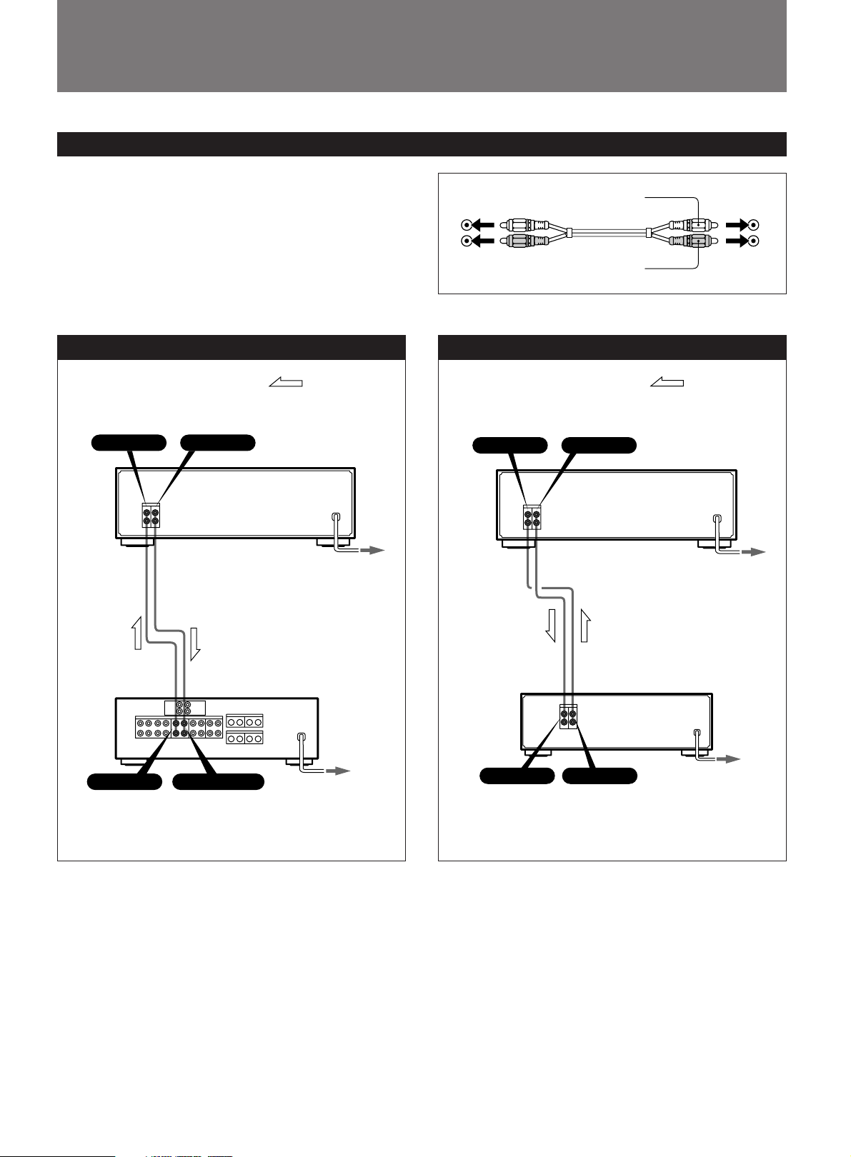
•Note that the red plug of the supplied connecting cord is
for right-channel (R) connection and the white plug for leftchannel (L) connection.
•The connecting cords should be fully inserted into the jacks.
A loose connection may cause hum pickup.
White
L
R
Red
L
R
Hooking Up an Amplifier
LINE IN LINE OUT
for
recording
for
playback
TC-K615S
to an AC (socket)
outlet
Amplifier
Signal flow
Hooking Up for Tape Dubbing
LINE IN LINE OUT
to another
tape deck
from another
tape deck
Another tape deck
Signal flow
TC-K615S
to a wall outlet
(mains)
REC OUT TAPE INPUT
to a wall outlet
(mains)
LINE IN
LINE OUT
to an AC (socket)
outlet
5

Identifying the Parts on the Front Panel
* Remote control sensor
1 2 3 4 5 7 8 9 !º !¡ !™ !£
dB –30 –20 –10 –4 0 +2 +4 +6 +8
–
∞
REC
DOLBY NR FILTER TYPE
P
0 AMS )
·
REC CAL
9
9
a
a
CS
B
TAPE
)
SOURCE TAPE
II IV
I
PAUSEPREC MUTERREC
POWER
L
H
R
L
(
MEMORY
COUNTER
RESET MEMORY
6
rp0
!•
For details, refer to the page number(s) indicated in
parentheses.
1 POWER switch
2 Peak level meter (page 12)
3 TAPE TYPE indicator
4 Linear counter (page 9)
5 MEMORY indicator
6 COUNTER buttons
RESET button (page 9)
MEMORY button (pages 9 and 10)
7 Cassette holder
8 DOLBY NR (noise reduction) switch (pages 7 and 10)
9 MPX FILTER button (page 12)
0 BIAS control (pages 14 and 15)
!¡ REC (recording) LEVEL control for calibration
(pages 14 and 15)
!™ REC (recording) LEVEL control (pages 11 and 12)
!£ BALANCE control (page 11)
!¢ HEADPHONES jack (stereo phone jack) (page 7)
!∞ CALIBRATION button (pages 14 and 15)
!§ MONITOR button (page 13)
•
–+
REC LEVEL
•
•
5
6
4
•
•
3
•
2
•
1
•
7
•
8
BALANCE
•
•
9
•
0
10
LR
HEADPHONES
MPX FILTER
ON OFFØø
DOLBY NR
OFF
•
EJECT
§
REC LEVEL
BIAS
•
B
•
C
•
•
S
–+
CALIBRATION
MONITOR
!¢!∞!§!¶
!¶ § (EJECT) button
!• Tape operation buttons
p (stop) button
0 (rewind) (Multi-AMS**) button
· (play) button
) (fast-forward) (Multi-AMS**) button
P PAUSE button
R REC MUTE (record muting) button (page 15)
r REC (recording) button
* Remote control sensor
You can remotely control this cassette deck with:
— A remote commander that came with a Sony amplifier
or receiver if it has the g mark and cassette deck control
capability.
— An optional Sony remote commander with the g mark
and cassette deck control capability.
** AMS is an abbreviation for Automatic Music Sensor.
6
 Loading...