

Sony TCEX-66 Service manual

TC-EX66
SERVICE MANUAL
This set is the cassette deck section
in MHC-EX66.
Dolby noise reduction manufactured under license
from Dolby Laboratories Licensing Corporation.
“DOLBY” and the double-D symbol a are trademarks
of Dolby Laboratories Licensing Corporation.
SPECIFICATIONS
AEP Model
UK Model
E Model
Model Name Using Similar Mechanism NEW
T ape Transport Mechanism Type
TCM-ACLM578
MICROFILM
STEREO CASSETTE DECK
SERVICING NOTES
(
)
(
)
TABLE OF CONTENTS
Servicing Notes ............................................................... 2
1. GENERAL
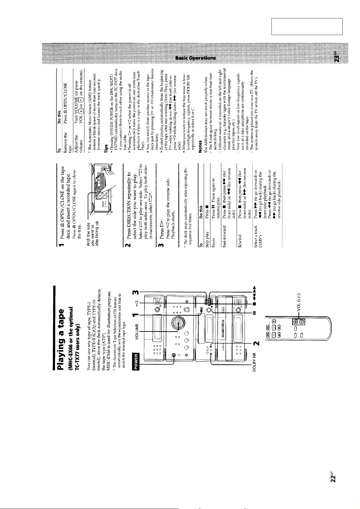
Playing a Tape ................................................................ 3
Recording on a Tape Manually....................................... 4
Recording the favorite CD Tracks on a Tape.................. 5
2. DISASSEMBLY ........................................................ 6
3. MECHANICAL ADJUSTMENTS ...................... 10
4. ELECTRICAL ADJUSTMENTS ........................ 10
5. DIAGRAMS
5-1. Printed Wiring Boards .................................................... 15
5-2. Schematic Diagram ........................................................ 19
5-3. IC Pin Function .............................................................. 25
6. EXPLODED VIEWS ............................................... 27
7. ELECTRICAL PARTS LIST............................... 32
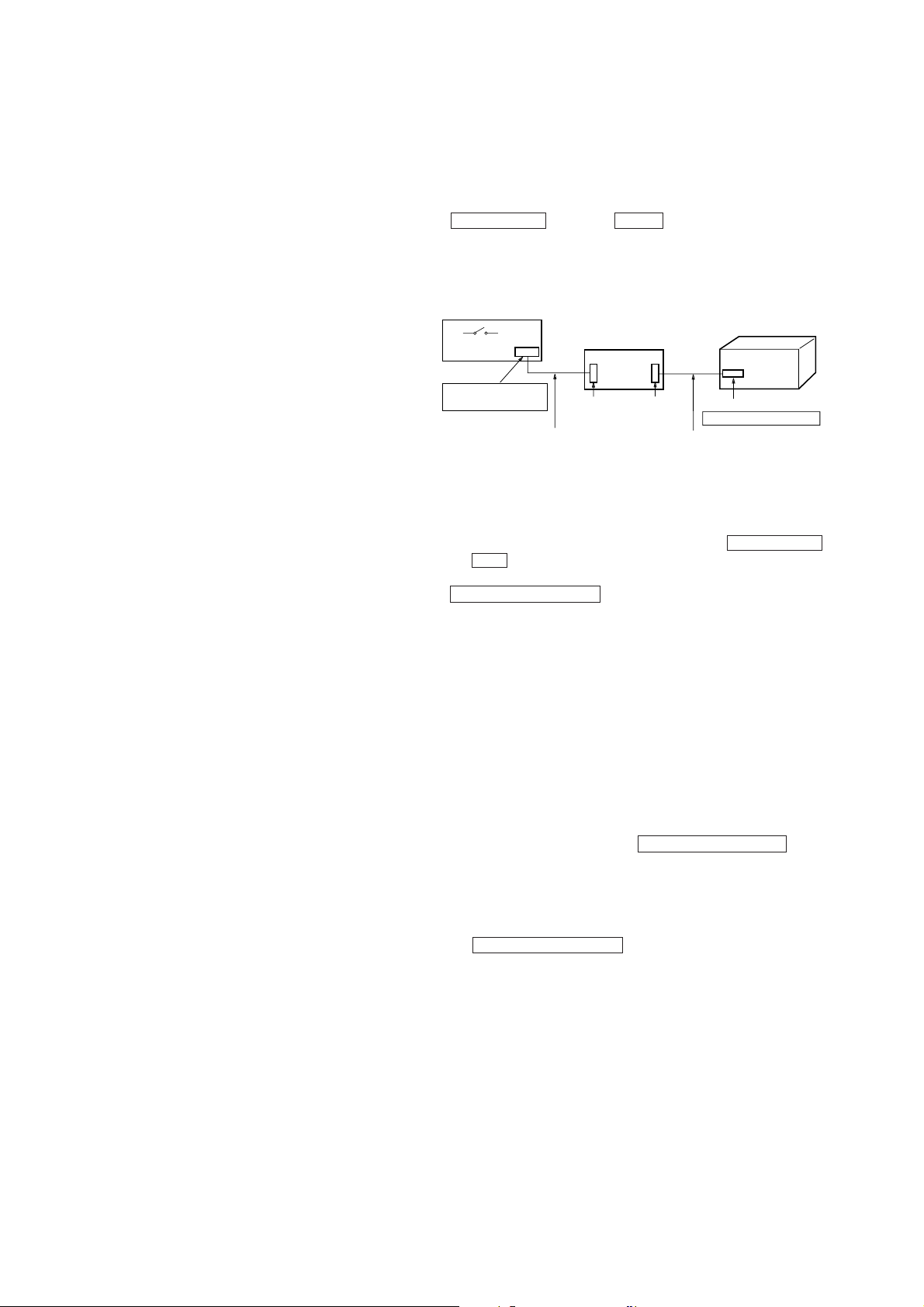
How to operate with a single unit.
Normally, this set is not operated with its own.
The exclusive jig (J-2501-078-A) and service box (PFJ-1) are necessary to operate the set with a single unit.
Turn the power set of the service box ON. Then press the
ENTER/NEXT button and SLEEP button at the same time to
turn the power on.
Connection:
SERVICE BOX (PFJ-1)
POWER SW
FH-E939, 838,937
CDP/TC
CORD WITH CONNECTOR 17P
attached to PFJ-1
JIG
(J-2501-078-A)
CN904
17P
CN902
7P
SET
CN101 7P
SYSTEM CONTROL
CORD WITH CONNECTOR 7P
attached to set
• KEY/FL tube/LED check mode.
T o enter KEY/FL tube/LED check mode, press the ENTER/NEXT
and REC buttons at the same time.
Under mode, every time when press any key or turn
MULTI CONTROLLER knob, change to next situation.
1 All LED indicators light on
2 All FL tube indicators light on
3 A part of FL tube light on mode 1. (Indicated ST-SEG)
4 A part of FL tube light on mode 2. (Indicated RDS-SEG)
5 KEY check mode
Note:
1) All LED light on mode is kept, when buttons which is pressed
to enter all LED light on mode, release same time.
When release them separate timing, it is moved to next All
LED light on mode.
2) After all LED light on mode, light on point remove one by one,
when any button pressed or MULTI CONTROLLER knob
turned.
3) Under KEY check mode, every time buttons pressed numerical value of “KEY” in FL tube increase.
And that time, numerical value of “ECDR” increase when
MULTI CONTROLLER button turn to + direction, and it
decrease turn to – direction.
When you want to finish this mode, unplug the power of amplif ier
or turn off PFJ-1 of POWER switch.
– 2 –
SECTION 1
GENERAL
This section is extracted
from instruction manual.
– 3 –

– 4 –

– 5 –

• This set can be disassembled in the order shown below.
SECTION 2
DISASSEMBLY
CASE,
FRONT PANEL
(Page 6)
Note: Follow the disassembly procedure in the numerical order given.
MECHANISM DECK
(Page 7)
MAIN BOARD
(Page 7)
CASE, FRONT PANEL
2
case
1
two screws
(case 3 TP 2)
8
lid (R-TC)
MECHANISM
CHASSIS SECTION
(Page 8)
TRY ASS’Y
(Page 8)
CAPSTAN MOTOR
(Page 9)
4
flat cable
(27 core)
(CN802)
7
front panel
6
three claws
5
screw
(BVTP3
1
two screws
(case TP2)
3
flat cable
(5 core)
(CN301)
5
two screws
(BVTP 3
×
8)
×
8)
– 6 –

MECHANISM DECK
3
mechanism deck
2
four screws
(BVTP3
×
8)
1
two connectors
(CN803, 804)
MAIN BOARD
1
3
two screws
(BVTP3
Slide the tray to
deviation of the arrow
1
connector
(CN351)
2
three connectors
(CN351, 803, 804)
×
8)
6
main board
A
.
4
two screws
(BVTP3
×
10)
A
– 7 –
5
two PCB holders

TRAY ASS’Y
5
tray ass’y
1
screw
(M1.7
×
8.2)
4
arm 576
MECHANISM CHASSIS SECTION
3
boss
3
mechanism chassis section
2
tension spring
1
four screws
(BK3
×
6)
2
screw (P3 × 8)
– 8 –
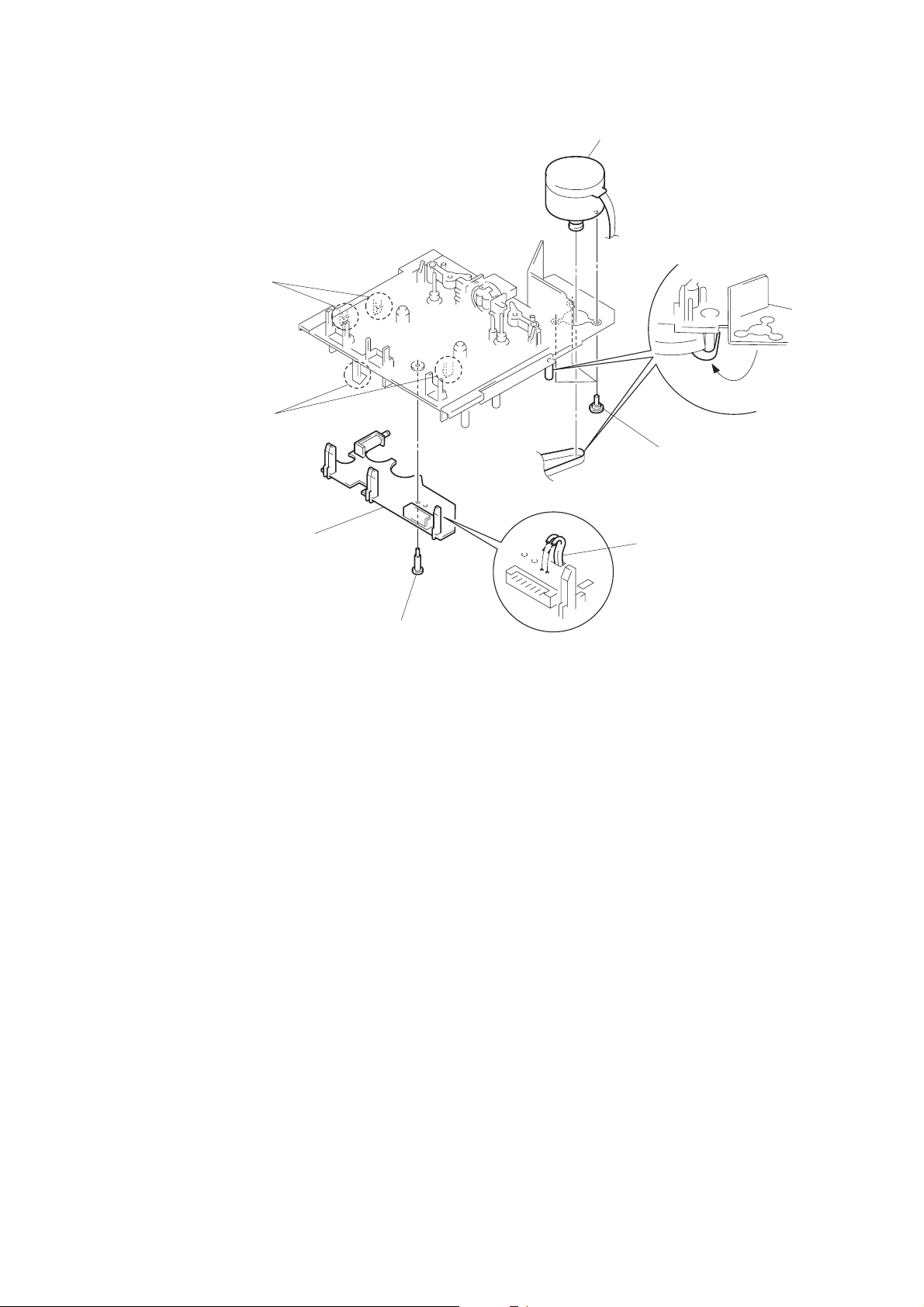
CAPSTAN MOTOTR
2
two claws
2
two claws
3
control board
7
capstan motor
6
three motor
screws.
4
Remove the solder
of motor lead wire.
5
Hang the belt.
1
step screw
– 9 –
 Loading...