

Page 1

3-206-661-11 (3)
Sim ultaneous
Interpretation
Conference System
Operating Instructions
Before operating the unit, please read this manual thoroughly
and retain it for future reference.
SX-M700A Control Unit
SX-C700A/C750 Chairman’s Unit
SX-D700A/D750 Delegate’s Unit
SX-P700 Interpreter’s Unit
2001 Sony Corporation
Page 2
Owner’s Record
WARNING
The model and serial numbers are located on the rear of the
SX-M700A and on the bottom of the SX-C700A/C750/
D700A/D750/P700. Record the serial numbers in the spaces
provided below. Refer to them whenever you call upon your
Sony dealer regarding these products.
Model No. SX-M700A Serial No.______________
Model No. SX-C700A/C750 Serial No.______________
Model No. SX-D700A/D750 Serial No.______________
Model No. SX-P700 Serial No.______________
For the customers in Canada
This Class A digital apparatus complies with Canadian
ICES-003.
W ARNING
To prevent fire or shock hazard, do not
expose the unit to rain or moisture.
For the customers in the U.S.A.
This equipment has been tested and found to comply with
the limits for a Class A digital device, pursuant to Part 15 of
the FCC Rules. These limits are designed to provide
reasonable protection against harmful interference when the
equipment is operated in a commercial environment. This
equipment generates, uses, and can radiate radio frequency
energy and, if not installed and used in accordance with the
instruction manual, may cause harmful interference to radio
communications. Operation of this equipment in a residential
area is likely to cause harmful interference in which case the
user will be required to correct the interference at his own
expense.
You are cautioned that any changes or modifications not
expressly approved in this manual could void your authority
to operate this equipment.
The shielded interface cable recommended in this manual
must be used with this equipment in order to comply with the
limits for a digital device pursuant to Subpart B of Part 15 of
FCC Rules.
This symbol is intended to alert the user to
the presence of uninsulated “dangerous
voltage” within the product’s enclosure that
may be of sufficient magnitude to
constitute a risk of electric shock to
persons.
This symbol is intended to alert the user to
the presence of important operating and
maintenance (servicing) instructions in the
literature accompanying the appliance.
2
Page 3
NOTICE FOR THE CUSTOMERS IN THE
UNITED KINGDOM
WARNING
THIS APPARATUS MUST BE EARTHED
IMPORTANT
The wires in this mains lead are coloured in accordance with
the following code:
Green-and-yellow: Earth
Blue: Neutral
Brown: Live
As the colours of the wires in the mains lead of this
apparatus may not correspond with the coloured markings
identifying the terminals in your plug proceed as follows:
The wire which is coloured green-and-yellow must be
connected to the terminal in the plug which is marked by the
letter E or by the safety earth symbol I or coloured green or
green-and-yellow.
The wire which is coloured blue must be connected to the
terminal which is marked with the letter N or coloured black.
The wire which is coloured brown must be connected to the
terminal which is marked with the letter L or coloured red.
For the customers in Europe
This product with the CE marking complies with both the
EMC Directive (89/336/EEC) and the Low Voltage Directive
(73/23/EEC) issued by the Commission of the European
Community.
Compliance with these directives implies conformity to the
following European standards:
• EN60950: Product Safety
• EN55022 class B: Electromagnetic Interference (Emission)
• EN55024: Electromagnetic Susceptibility (lmmunity)
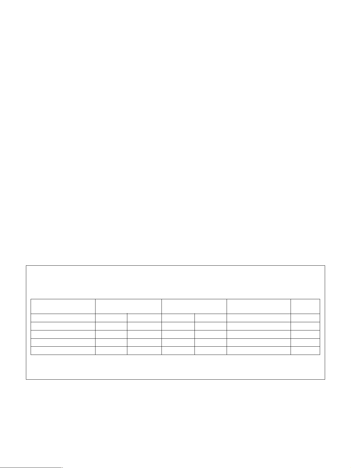
Warning on power connection
Use a proper cord for your local power supply.
United States, Continental Europe United Kingdom, Ireland, Japan
Canada Australia,New Zealand
Plug type VM0234 290B 1610 YP-12A * VM1072
Female end VM0089A 386A 1698 YC-13B VM0310B VM1289
Cord type SJT SJT H05VV-F H05VV-F N13237/CO-288 HVCTF
Minimum cordset rating 10A/125V 10A/125V 10A/250V 10A/250V 10A/250V 7A/125V
Safety approval UL/CSA UL/CSA VDE VDE VDE DENAN
* Note: Use an appropriate rating plug which is applied to local regulations.
3
Page 4

4
Page 5

Table of Contents
Outline ...................................................................................................... 6
Features..........................................................................................................6
System Configuration ....................................................................................7
Location and Function of Parts and Controls....................................... 8
SX-M700A Control Unit ...............................................................................8
SX-C700A/C750/SX-D700A/D750 Chairman’s Unit/Delegate’s Unit ......11
SX-P700 Interpreter’s Unit..........................................................................14
Setting Up the System........................................................................... 16
Precautions...................................................................................................16
System Connection ......................................................................................16
Turning On the Power of the System ..........................................................18
Assigning Interpreted Languages to Channels ............................................18
Preparing the Control Unit...........................................................................18
Operation During a Conference ........................................................... 20
Operations Performed by the Chairman and Delegates...............................20
Interpreter’s Operations ...............................................................................21
Troubleshooting Guide ......................................................................... 23
Specifications ........................................................................... Back cover
5
Page 6

Outline
Features
The SX-M700A simultaneous interpretation
conference system is designed to allow delegates’
speeches to be interpreted into a maximum of six
languages. Delegates in a conference hall can thus
listen to any of the interpreted languages.
The standard system supports a conference of up to
60 delegates. Connecting the SX-E120A Expansion
Unit (not supplied) allows the system to support up to
120 delegates.
The standard system consists of the following units.
•SX-M700A Control Unit
This unit controls the simultaneous interpretation
conference system.
The control unit can be mounted in a 19-inch rack.
•Chairman’s Unit/Delegate’s Unit
– SX-C700A/D700A Chairman’s Unit/Delegate’s
Unit: Desktop type. You can move these units
freely in the conference room.
– SX-C750/D750 Chairman’s Unit/Delegate’s Unit:
Desk-mounted type. These units are fixed to the
desks.
These units feature both a microphone and speaker.
Use the above combination of the chairman’s unit
and delegate’s unit.
•SX-P700 Interpreter’s Unit
This unit, connected to the control unit, is used by a
simultaneous interpreter.
In addition to the units described above, the following
optional units are available.
SXA-120 Expansion Board
The board is designed to allow the expansion of the
system’s functions. Installing this board in the control
unit allows the following function expansion units to
be connected.
•SX-E120A Expansion Unit
•SX-S100 Microphone Control Panel
Used to enable or disable delegates’ microphones.
•Personal computer
For details of the SXA-120 Expansion Board, refer to the
manual supplied with the expansion board.
6
Page 7
System Configuration
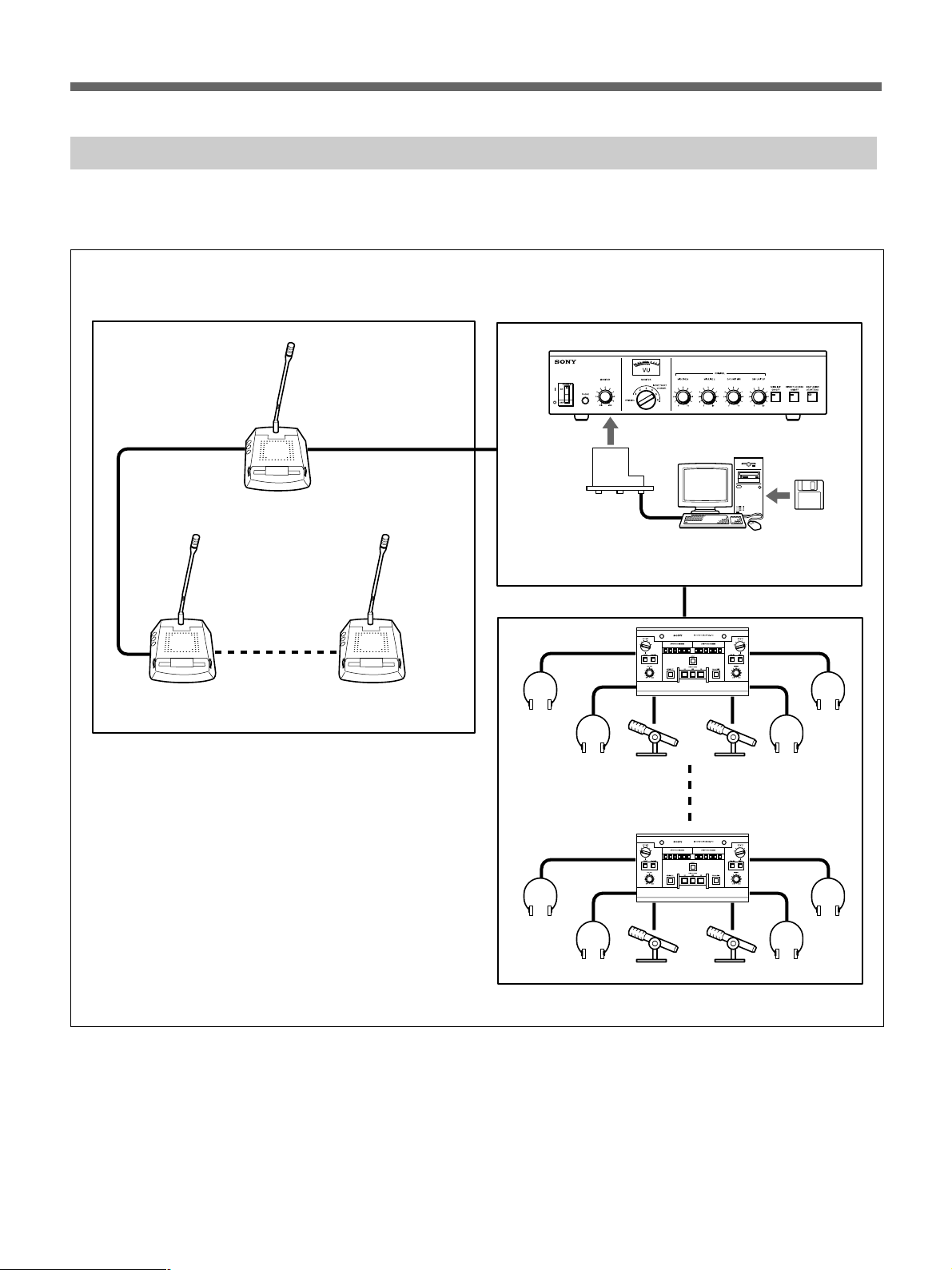
The figure below shows an example of the simultaneous interpretation system.
Conference hall
Conference seats
DX-D700A Delegate’s Unit
SX-C700A Chairman’s Unit
a)
Operator section
SX-M700A Control Unit
a)
Interpreter’s booth
SXA-120
Expansion
Board
SX-P700
Interpreter’s Unit
SX-GS10
Conference
Management
Software
a) You can also use other combination of the SX-C750/D750.
7
Page 8
Location and Function of Parts and Controls
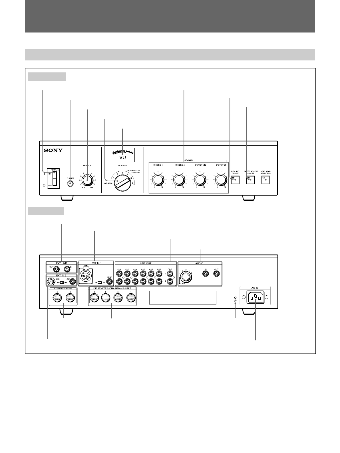
SX-M700A Control Unit
Front panel
1POWER switch
Rear panel
0EXT UNIT IN/OUT connectors
2PHONES connector
3MONITOR volume control
4MONITOR channel selector
qaEXT IN-1 MIC/LINE connectors and MIC/LINE switch
5Level meter
6ORIGINAL volume controls
7MIC LIMIT ON/OFF button
8DIRECT ACCESS
ON/OFF button
9SEAT ASSIGN
START/END button
qsLINE OUT connectors
qdTV conference system, etc. connecting section
qgINTERPRETER’S
UNIT connectors
qfEXT IN-2 MIC/LINE connectors and MIC/LINE switch
1POWER switch
Setting the switch to ON (!) turns the power on. The
level meter will light.
Setting the switch to OFF (a) turns the power off.
2PHONES connector (stereo phone jack)
Connect 8-ohm stereo or monaural headphones. Note
that the output is monaural even when stereo
headphones are connected.
qhDELEGATE’S/CHAIRMAN’S UNIT
connectors
8
qjU terminal
qkAC IN connector
3MONITOR volume control
Adjusts the volume of the headphones.
4MONITOR channel selector
Selects the channel corresponding to the interpreted
language to be monitored through the headphones
(INTERPRETER CHANNEL 1 to 6). To monitor the
original speech, set the selector to ORIGINAL.
Page 9

5Level meter
Indicates the output level of the audio signal selected
by the MONITOR channel selector 4. When the
MONITOR channel selector is set to ORIGINAL, the
level meter also indicates the level of the original
sound output to the LINE OUT qs, AUDIO IN/OUT
qd, and INTERPRETER’S UNIT qg connectors.
6ORIGINAL volume controls
Used to adjust the level of the following sound.
D/C UNIT SP volume control: Adjusts the level of
the audio signal output to the chairman’s unit/
delegate’s unit.
D/C UNIT MIC volume control: Adjusts the input
level of the audio signal sent from the microphones
on the chairman’s units and delegate’s units.
MIC/LINE 1 volume control: Adjusts the input level
of the signal input through the EXT IN-1 MIC or
LINE connector.
MIC/LINE 2 volume control: Adjusts the input level
of the signal input through the EXT IN-2 MIC or
LINE connector.
When the MIC/LINE switch of the EXT IN-1 or EXT
IN-2 connector is set to LINE, the input level of the
signal input through the LINE connector can be
adjusted.
When the MIC/LINE switch of the EXT IN-1 or EXT
IN-2 connector is set to MIC, the input level of the
signal input through the MIC connector can be
adjusted.
7MIC (microphone mode) LIMIT ON/OFF
button
Selects the microphone mode for the delegate’s units.
The microphone of the chairman’s unit remains live
regardless of the setting of this button.
MIC (microphone) LIMIT ON: Press this button to
set the microphone to the speaker’s number limitation
mode. The button indicator lights. Setting this mode
allows the microphones of up to five delegate’s units
to be live at the same time.
MIC (microphone) LIMIT OFF: Press the button
again to set the microphone to the speaker’s number
unlimitation mode. The button indicator goes out.
Setting this mode allows the microphones of all
delegate’s units to be live at the same time.
8DIRECT ACCESS ON/OFF button
Not used.
9SEAT ASSIGN START/END button
Not used.
0EXT UNIT IN/OUT (external unit input/
output) connectors (phone jack)
Connect to the howling suppressor unit or filter unit
(not supplied).
Notes
•Be sure to connect both the IN and OUT connectors.
Connecting only one of the two connectors results in
incorrect operation of the unit.
•When it is not necessary to use the howling
suppressor or filter unit, disconnect cables from both
connectors.
qaEXT IN-1 MIC/LINE (external 1 microphone/
line signal input) connectors and MIC/LINE
switch
EXT IN-1 MIC/LINE connectors
Accept an external audio signal.
MIC connector (XLR type): Connect a rostrum or
conference hall microphone.
Note
When you use a connecting cable with an XLR
connector, pin No.1 and the case (metal part) of
which are connected, noise may be picked up.
LINE connector (phono jack): Connect to external
equipment such as audio equipment.
MIC/LINE switch
Selects the signal input to the EXT IN-1 connector.
MIC: Set the switch to this position when a
microphone is connected.
LINE: Set the switch to this position when an item of
audio equipment is connected.
9
Page 10

Location and Function of Parts and Controls
qsLINE OUT (line output) connectors (phono
jacks)
Supply the original signal from the chairman’s unit/
delegate’s unit, that from the rostrum or conference
hall microphone, as well as the six channel
simultaneously interpreted output signals. There are
two connectors for each channel. Use these
connectors when recording the output to a tape
recorder or when sending the line output to the
monitor system transmitter by means of an infrared or
induction-based system.
The original sound is also output automatically from
any channel that is not being used for simultaneous
interpreting.
qdTV conference, etc. connecting section
AUDIO IN/OUT (audio input/output) connectors
(phono jack)
Connect to the TV conference system and so on.
Channel selector
Selects the channel to be output to the AUDIO OUT
connector.
qhDELEGATE’S/CHAIRMAN’S UNIT
connectors (20-pin multi-connectors)
Connect to the SX-C700A/C750/SX-D700A/D750
Chairman’s Unit/Delegate’s Unit. The same signal is
output from four connectors. Up to 15 SX-C700A/
C750/SX-D700A/D750 units can be connected to
each of the four connectors. Thus, up to 60 SXC700A/C750/SX-D700A/D750 units can be
connected.
Note
A dust cap is attached to each of the
INTERPRETER’S UNIT connectors qg and
DELEGATE’S/CHAIRMAN’S UNIT connectors qh.
Keep the dust caps on any connectors which are not
being used.
qjU (signal ground) terminal
Ground if necessary.
qkAC IN (AC power input) connector
Connect the unit to an AC power source by means of
the supplied AC power cord.
qfEXT IN-2 MIC/LINE (external 2 microphone/
line signal input) connectors and MIC/LINE
(microphone/line signal select) switch
EXT IN-2 MIC/LINE connectors
Input an external audio signal.
MIC connector (phone jack): Connect a rostrum or
conference hall microphone.
LINE connector (phono jack): Connect to external
equipment such as audio equipment.
MIC/LINE switch
Selects the signal input to the EXT IN-2 connector.
MIC: Set the switch to this position when a
microphone is connected.
LINE: Set the switch to this position when an item of
audio equipment is connected.
qgINTERPRETER’S UNIT connectors (20-pin
multi-connectors)
Connect to the SX-P700 Interpreter’s Units. The same
signal is output from two connectors. Up to seven
SX-P700 units can be connected to the two
connectors.
10
Page 11
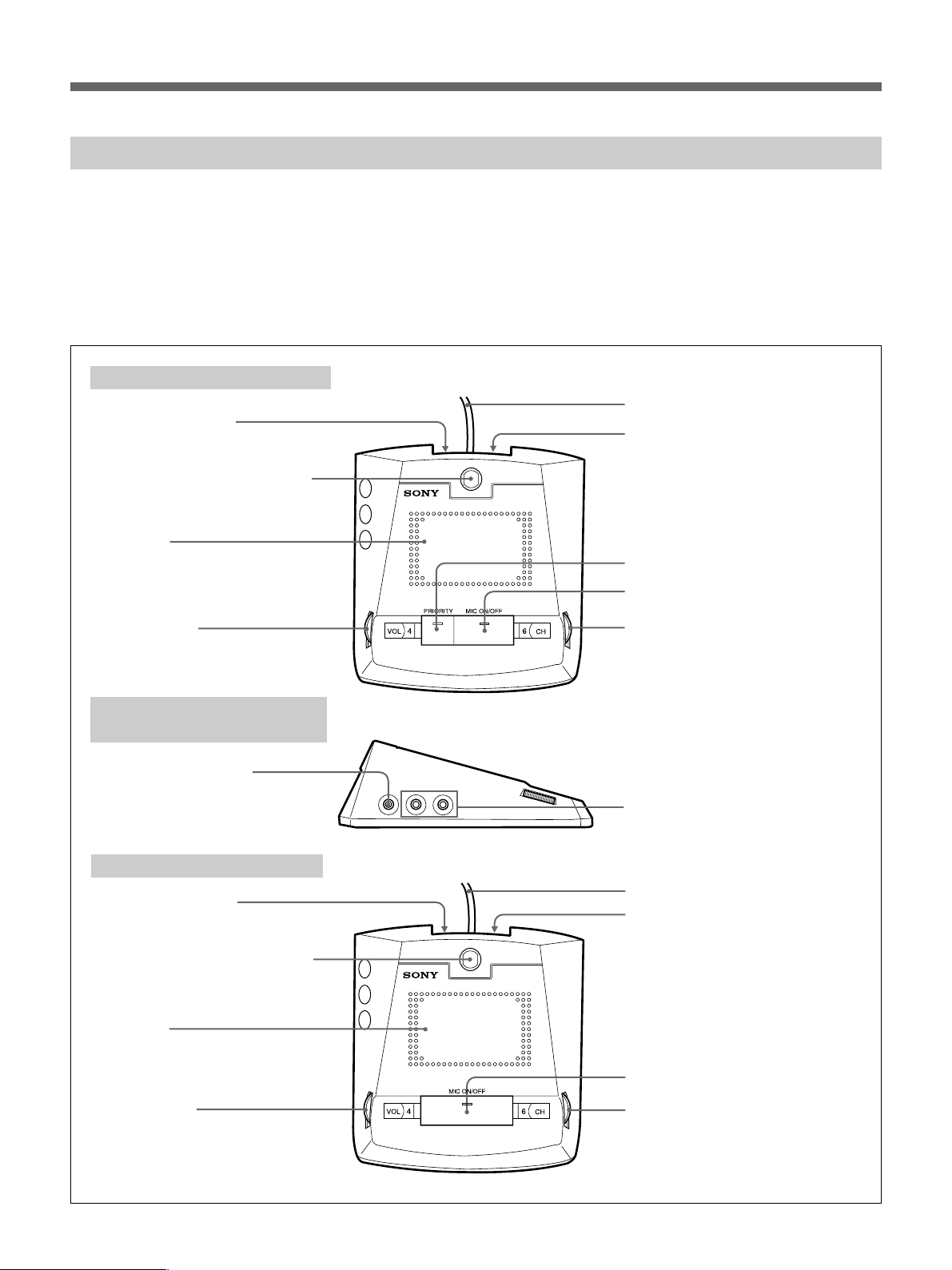
SX-C700A/C750/SX-D700A/D750 Chairman’s Unit/Delegate’s Unit
The following two combinations of the chairman’s
unit and delegate’s unit are available for use with the
system.
•SX-C700A/D700A Chairman’s Unit/Delegate’s Unit
•SX-C750/D750 Chairman’s Unit/Delegate’s Unit
SX-C700A/D700A Chairman’s Unit/Delegate’s Unit
Chairman’s unit front panel
1Output connector
2Microphone and microphone
indicator
Speaker
3
4VOL control
This section explains the location and function of
parts and controls of the chairman’s unit and
delegate’s unit. The explanation applies to both
combinations. Read the explanation corresponding to
the numbered parts and controls in the illustration.
5Cable with 20-pin multi-connector
6Voting connector
7PRIORITY button and indicator
8MIC ON/OFF button and indicator
9CH selector
Chairman’s unit/delegate’s
unit side panel
0REC OUT connector
Delegate’s unit front panel
1Output connector
2Microphone and microphone
indicator
3Speaker
4VOL control
qaEarphone jacks
5Cable with 20-pin multi-connector
6Voting connector
8MIC ON/OFF button and indicator
9CH selector
11
Page 12
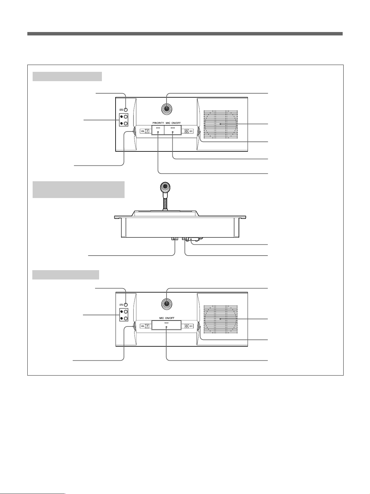
Location and Function of Parts and Controls
SX-C750/D750 Chairman’s Unit/Delegate’s Unit
Chairman’s unit top
q;REC OUT connector
qaEarphone jacks
4VOL control
Chairman’s unit/delegate’s
unit bottom
1Output connector
2Microphone and
microphone indicator
3Speaker
9CH selector
8MIC ON/OFF button and
indicator
7PRIORITY button and
indicator
6Voting connector
5Input connector
Delegate’s unit top
q;REC OUT connector
qaEarphone jacks
4VOL control
The explanations given here apply to both units,
unless noted otherwise, with the exception of
PRIORITY button 7.
1Output connector (20-pin multi-connector)
(for SX-C700A/D700A only)
Connect the cable with a 20-pin multi-connector of
the chairman’s unit/delegate’s unit placed opposite
the SX-M700A Control Unit and the next chairman’s
unit/delegate’s unit.
12
2Microphone and
microphone indicator
3Speaker
9CH selector
8MIC ON/OFF button
and indicator
1Output connector (D-sub 15-pin)
(for SX-C750/D750 only)
Connect to the input connector of the next chairman’s
unit or delegate’s unit using the cable with D-sub 15pin connectors.
2Microphone and microphone indicator
The microphone can be rotated freely. The
microphone operation depends on the setting of the
MIC ON/OFF button 8.
For details, see the explanation of the MIC ON/OFF button
8 of the control unit.
Page 13

3Speaker
The original sound is heard through this speaker
regardless of the setting of the CH selector 9, when
the microphone is not being used and when an
earphone is not plugged into the earphone jack. The
speaker’s volume is adjusted from the SX-M700A
Control Unit. To prevent howling, nothing is output
from the speaker when the microphone of the
chairman’s/delegate’s unit is enabled. Also at the
same time, the speaker volume of the units on either
sides of the unit is automatically reduced.
4VOL (volume) control
Adjusts the volume of the earphone. Even if the
VOLUME control is turned fully counterclockwise,
the earphone volume cannot be turned off. (The
speaker volume is not affected by this control.)
5Cable with 20-pin multi-connector (for SX-
C700A/D700A only)
Connect to the DELEGATE’S/CHAIRMAN’S UNIT
connector of the SX-M700A Control Unit, SX-E120A
Expansion Board (not supplied) or the output
connector of another chairman’s unit/delegate’s unit.
5Input connector (D-sub 15-pin) (for SX-
C750/D750 only)
Connect to the DELEGATE’S/CHAIRMAN’S UNIT
connector of the SX-M700A Control Unit, SX-E120A
Expansion Board (not supplied) or the output
connector of another chairman’s unit/delegate’s unit.
6Voting connector
Connect to the SX-CV10/DV10 voting unit (not
supplied).
For details, contact your Sony dealer.
Pressing this button again turns the microphone
off. The indicators go out.
SX-D700A/D750: When the MIC LIMIT ON/OFF
button on the control unit is set to OFF (the MIC
LIMIT ON/OFF button indicator does not light),
pressing this button turns the microphone on. The
MIC ON/OFF button indicator and microphone
indicator 2 light. In this mode, since the number
of speakers is not limited, the microphones of all
the delegate’s units are enabled.
When the MIC LIMIT ON/OFF button on the
control unit is set to ON (the MIC LIMIT ON/OFF
button indicator is lit), the number of speakers is
limited. Thus, when the MIC ON/OFF buttons of
more than six delegate’s units are pressed at the
same time, the indicator of the sixth delegate’s unit
blinks (for about 3 seconds) to tell the user that the
microphone cannot be enabled since the number of
units whose MIC ON/OFF button is pressed
exceeds six.
9CH (channel) selector
Select the signal to be output to the earphone jack and
the REC OUT connector. You can select either the
original signal, or channel 1 to channel 6.
0REC OUT (recording output) connector
(minijack)
Connect to the input connector of the tape recorder to
record the monitor sound. To record a signal other
than the original signal, plug the earphone into the
earphone jack and select the channel corresponding to
the desired interpreted language with the CH selector
9. When the earphone is unplugged, the original
signal is output from this connector regardless of the
CH selector setting.
7PRIORITY button and indicator (for the
SX-C700A/C750 only)
Press this button to disconnect the microphones of the
delegate’s units and enable the use of only the
microphone of the chairman’s unit.
Holding down this button turns on the microphone of
the chairman’s unit.
The PRIORITY button blinks while the SLOW button
on the interpreter’s unit is held down.
8MIC ON/OFF button and indicator
SX-C700A/C750: Pressing this button turns the
microphone on. The MIC ON/OFF button
indicator and microphone indicator 2 light.
Note
Use a connecting cable with a terminating resistor
(RK-G64 and so on) to connect the unit to the
microphone input connector of a tape recorder.
Use a connecting cable without a terminating register
(RK-G69 and so on) to connect the unit to the line
input connector of a tape recorder.
qaEarphone jacks (minijack)
Connect an earphone to monitor the signal from the
interpreter’s unit or the original signal.
You can also connect the headphones with the mini
plug. However, only the monaural sound is output
through the headphones. Since the unit is equipped
with two earphone jacks, two persons can monitor the
signal at the same time.
13
Page 14
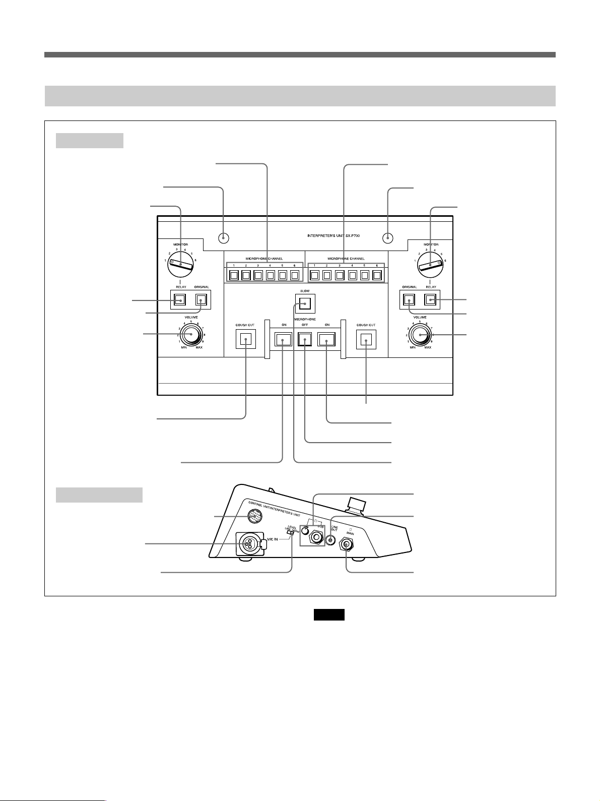
Location and Function of Parts and Controls
SX-P700 Interpreter’s Unit
Front panel
1MICROPHONE CHANNEL buttons
2Microphone indicator
3MONITOR selector
4RELAY button
5ORIGINAL button
6VOLUME control
7COUGH CUT button
1MICROPHONE CHANNEL buttons
2Microphone indicator
3MONITOR selector
4RELAY button
5ORIGINAL button
6VOLUME control
7COUGH CUT button
8MICROPHONE ON button
9MICROPHONE OFF button
8MICROPHONE ON button
Left side panel
qaCONTROL UNIT/INTERPRETER’S
UNIT connector
qsMIC IN connector
qdMIC IN LEVEL switch
The interpreter’s unit is designed to be used by two
interpreters. There are two sets of controls 1 to 8
on the left section and right section of the unit. Their
functions are exactly the same. Buttons 9 and 0 are
common to both left and right sections. Either of the
two interpreters can use these buttons.
Front panel
1MICROPHONE CHANNEL buttons
Press the button corresponding to the channel for the
target language (channel 1 to channel 6) such that the
indicator lights.
14
0SLOW button
qf
SUB headphones connector
and volume control
qgLINE OUT connector
qhMAIN headphones
connector
Notes
•Should you accidentally press the wrong button
while you are interpreting, your voice will be output
on the wrong channel.
•When the system power is turned on or the power is
turned off and back on again, channel 1 is
automatically selected (the button of channel 1
automatically lights).
2Microphone indicator
Lights when the MICROPHONE ON button is
pressed. While this indicator is lit, the corresponding
interpreter’s microphone is enabled.
Page 15

3MONITOR selector
Selects the channel of the language to be monitored
when relay interpreting is being performed. This
selector is effective only when the RELAY button 4
is pressed.
Left side panel
The following connectors and switches qa, qs, qd, qf
and qh are located on both sides of the interpreter’s
unit. The LINE OUT connector qg is provided only
on the left side.
4RELAY button
Used to perform relay interpreting. Press to monitor
the language selected with the MONITOR selector 3
through the headphones (the button lights).
5ORIGINAL button
Press to monitor the original signal through the
headphones (the button lights).
RELAY button and ORIGINAL button
When the RELAY button is pressed, it lights and the
ORIGINAL button goes out. The interpreter can then
monitor the language selected with the MONITOR
selector 3. When the ORIGINAL button is pressed,
it lights and the RELAY button goes out. The
interpreter can monitor the original signal.
When the system power is turned on or the power is
turned off and back on again, the ORIGINAL button
automatically lights.
6VOLUME control
Adjusts the volume of the main headphones of the
main interpreter.
7COUGH CUT button
Press to disable the microphone temporarily. The
microphone is disabled and the microphone indicator
2 does not light for as long as the interpreter holds
down the button.
8MICROPHONE ON button
Press this button to enable the microphone. The
microphone indicator lights while the microphone is
live. When another interpreter presses his or her
MICROPHONE ON button, this microphone is
disabled.
9MICROPHONE OFF button
Press the button to disable the microphone such that
the MICROPHONE ON button goes out.
qaCONTROL UNIT/INTERPRETER’S UNIT
connector (20-pin multi-connector)
Two connectors on the left and right sections have the
same function. Connect to the CONTROL UNIT/
INTERPRETER’S UNIT connector of the next
interpreter’s unit by using the RK-1705/1700
connecting cable (5m or 16.4 feet/10m or 32.8 feet)
(not supplied). When the interpreter’s unit is placed
next to the SX-M700A Control Unit, connect to the
INTERPRETER’S UNIT connector of the control
unit.
qsMIC IN (microphone input) connector (XLR
3-pin)
Connect a microphone having an XLR connector.
qdMIC IN LEVEL switch
Selects the output level of the microphone connected
to the MIC IN connector.
NORM (normal): Normally, set the switch to this
position.
LOW: Set the switch to this position when a
microphone having a low output level is being
used.
qfSUB headphones connector (phone jack)
and volume control
Connect 8-ohm headphones for the sub-interpreter.
Adjust the volume of the sub-headphones with this
volume control.
qgLINE OUT (output) connector (phono jack)
(left section only)
Connect a speaker having a built-in amplifier. The
language which can be heard through the connected
speaker depends on the setting of the MONITOR
selector 3, RELAY button 4 and ORIGINAL
button 5 of the left section. When the interpreter
turns on the microphone, this speaker is automatically
muted.
0SLOW button
Press to request that the speaker speaks slowly. While
the interpreter is holding down this button, the
PRIORITY button on the chairman’s unit blinks.
qhMAIN headphones connector (phone jack)
Connect 8-ohm headphones for the main interpreter.
Either stereo or monaural headphones can be used.
The monaural sound, however, is output from the
headphones.
15
Page 16

Setting Up the System
Precautions
Safety precautions
Power supply
•Operate the unit only with a power source as
specified in “Specifications” section.
•Do not drop or place heavy objects on the power
cord. If the power cord is damaged, turn off the
power immediately. It is dangerous to use the unit
with a damaged power cord.
•Disconnect the power cord from the AC outlet by
grasping the plug, not by pulling the cord.
Keep foreign objects out of the cabinet
Dropping flammable or metal objects into the cabinet,
or spilling liquids onto the cabinet can lead to
accidents.
In case of malfunctions
If you notice any unusual sound, smell or smoke, turn
off the power immediately, disconnect the power
supply and contact your Sony dealer.
Cleaning
Clean the cabinet and panels by wiping with a soft,
dry cloth. For severe stains, moisten the cloth with a
small amount of neutral solvent, and finish by wiping
with a dry cloth. Do not use alcohol, benzine, thinner
or volatile liquids, as these may discolor or damage
the cabinet surface.
System Connection
This section explains how to connect the system.
Chairman’s unit/delegate’s unit and
interpreter’s unit
The SX-M700A Control Unit is provided with four
DELEGATE’S/CHAIRMAN’S UNIT connectors and
two INTERPRETER’S UNIT connectors. Up to 15
chairman’s/delegate’s units can be connected to each
of the DELEGATE’S/CHAIRMAN’S UNIT
connectors in serial connection. The distance between
the control unit and the last chairman’s/delegate’s unit
should not exceed 60 meters (196.8 feet).
A total of seven interpreter’s units can be connected
to the two INTERPRETER’S UNIT connectors. For
example, three units can be connected to one
connector and four units to the other. The distance
between the control unit and the last interpreter’s unit
should not exceed 60 meters (196.8 feet).
Notes
•Be sure to turn off the power of any units before
attempting connection or disconnection.
•If you turn on the system power before connecting
the chairman’s unit/delegate’s unit, the microphone
indicators and MIC ON/OFF buttons continue to
blink and these units cannot be controlled by the
control unit. In such a case, turn the power off, then
back on again.
•When using the INTERPRETER’S UNIT
connectors (20-pin multi-connector) and
DELEGATE’S/CHAIRMAN’S UNIT connectors
(20-pin multi-connector) of the control unit, attach
the dust caps removed from the 20-pin multiconnectors on the control unit to the 20-pin multiconnectors on the last unit connected.
If the 20-pin multi-connector has no dust cap, keep it
away from metal tools, such as screwdrivers to
prevent the connectors being inadvertently shorted.
16
Page 17
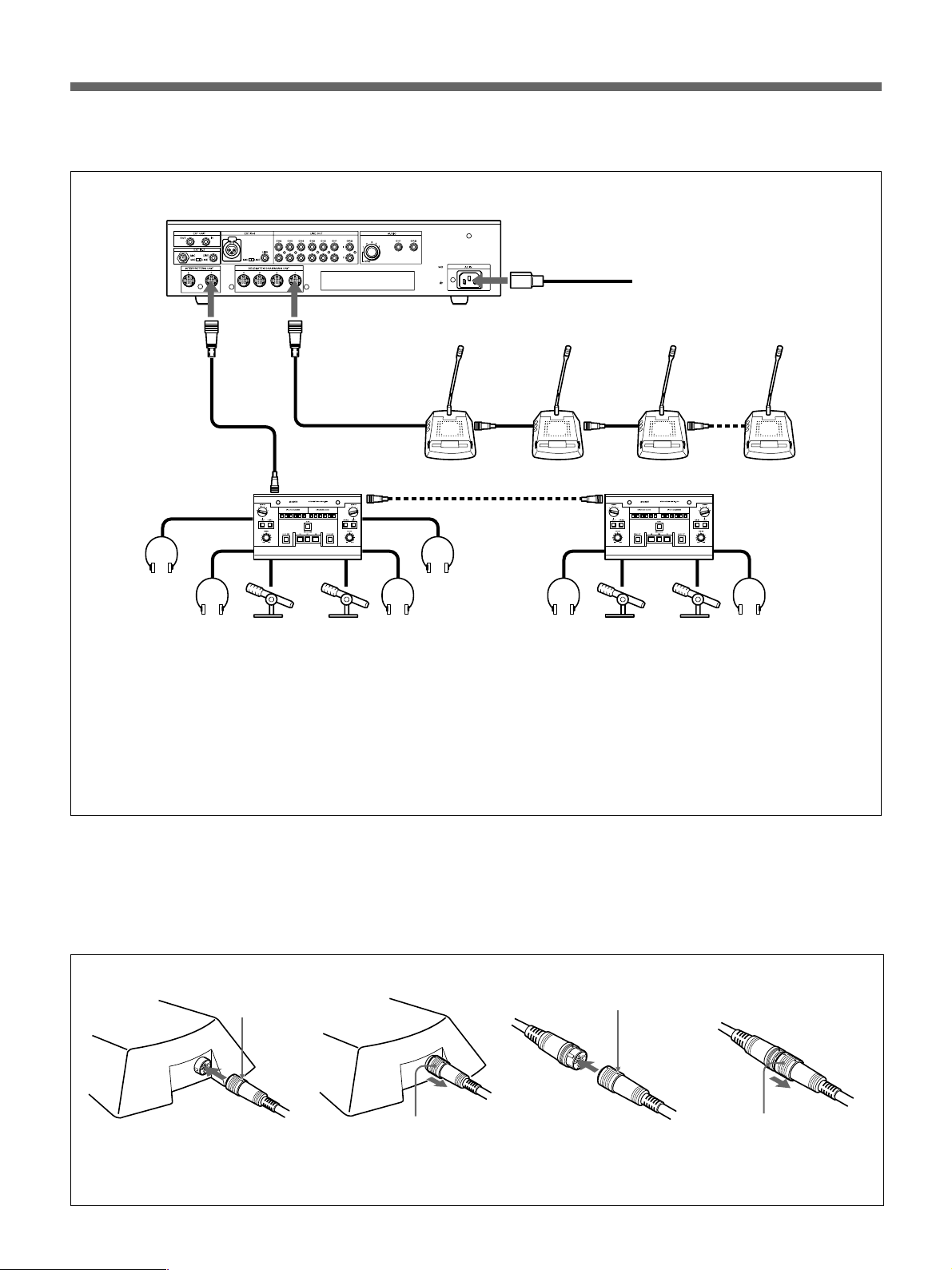
The figure below shows an connection example.
SX-M700A
INTERPRETER’S
a)
UNIT
DELEGATE’S/CHAIRMAN’S
a)
UNIT
AC IN
to AC power source
AC power cord
(supplied with SX-M700A)
Cable with 20-pin
multi-connector
c)
RK-1700/1705
connecting cable
(10 m/5 m)
(not supplied)
b)
CONTROL UNIT/
INTERPRETER’S
a)
UNIT
SX-C700A
SUB
MAIN
MIC IN
Sub-headphones
Main headphones
Microphones
a) For details of connecting cables, see “How to connect cables” shown below.
b) You can extend the distance between units up to 60 meters by using the RK-1710/1713 connecting cable
between the RK-1700/1705 connecting cable and the interpreter’s unit. Note, however, that the maximum
length must not exceed 60 meters (196.8 feet).
c) You can extend the distance between units by using the RK-1710/1713 connecting cable (not supplied).
d) The desk-mounted SX-C750/D750 can also be used in this system. Up to 15 desk-mounted SX-C750 and
SX-D750 units can be connected to one line.
The specially designed cables are used to connect these units to the system.
For details, contact your Sony dealer.
How to connect cables of SX-C700A/D700A
The figure below shows how to connect and
disconnect the 20-pin multi-connectors of the
chairman’s/delegate’s unit, RK-1700/1705 and RK1710/1713 connecting cables.
to output
connector
d)
a)
SX-D700A
SX-D700A can be connected to one line.)
RK-1700/1705
connecting cable (10 m/
5 m) (not supplied)
b)
d)
(Up to 15 units of SX-C700A and
SX-P700
When connecting
White mark
With the white mark on the 20-pin
multi-connector facing up, push
the connector home until it clicks.
When disconnecting
Grasp the knurled part of
the connector and pull it
towards you.
When connecting
White mark
Meet the white marks on each
connector and push the connectors
each other until they click.
When disconnecting
Grasp the knurled part
of the connector and
pull it towards you.
17
Page 18
Setting Up the System
Turning On the Power of the System
Control unit
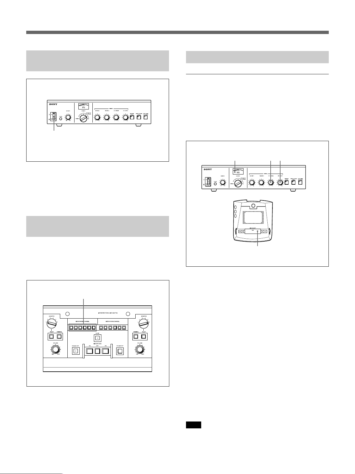
2
1 Turn on the power of the units connected to the
EXT IN-1/2 connectors of the control unit.
2 Set the POWER switch of the control unit to ON.
Assigning Interpreted Languages to Channels
Assign the interpreted languages to the channels (1 to
6) of the interpreter’s units by using the
MICROPHONE CHANNEL buttons of the
interpreter’s unit before the start of conference.
MICROPHONE CHANNEL buttons
Preparing the Control Unit
Adjusting the audio level
Adjust the audio signal output to the chairman’s/
delegate’s unit from external equipment connected to
EXT IN-1/2 before the conference.
Adjusting the output level of the audio signal
to the chairman’s unit/delegate’s unit
Level meter
3
2
Control unit
Chairman’s unit/
delegate’s unit
1
1 Select several chairman’s units/delegate’s units
placed in the hall and set their MIC ON/OFF
buttons to turn on their indicators.
Press the MICROPHONE CHANNEL button
corresponding to the channel assigned to the target
language of each interpreter.
18
2 Adjust the speaker volume on the chairman’s
units/delegate’s units so that the level meter
indicates around 0 VU using the D/C UNIT MIC
volume control on the control unit, while an
assistant in the conference hall is speaking into
the microphone.
3 If howling occurs, rotate the D/C UNIT SP
volume control counterclockwise to reduce the
volume until the howling stops.
If howling does not stop even if you rotate the
D/C UNIT SP volume control counterclockwise,
it is recommended to use the howling suppressor
or filter unit (not supplied).
Note
The person speaking into the microphone should
bring his/her mouth close to the microphone.
Page 19
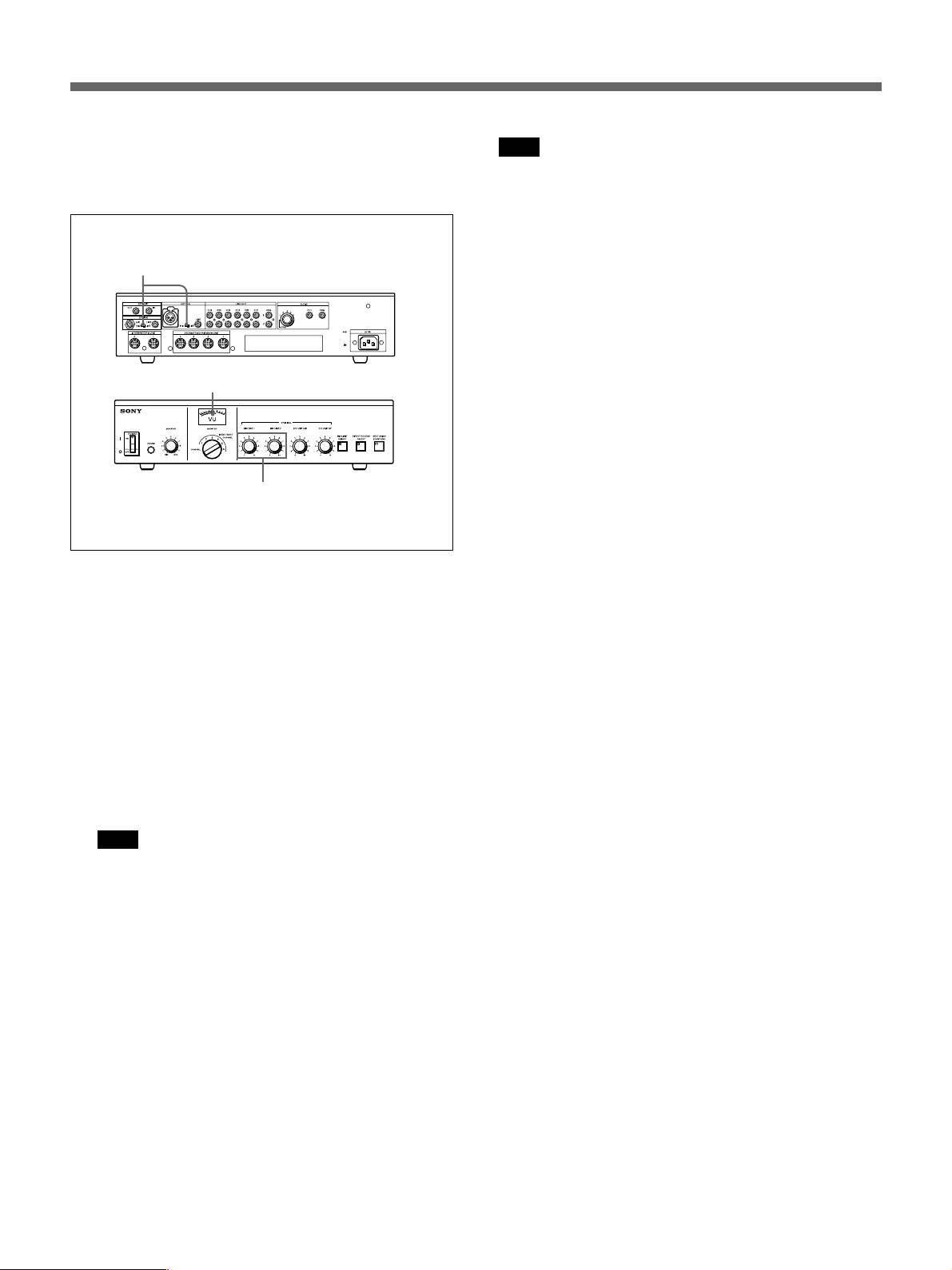
Adjusting the input level of the audio signal
from equipment connected to EXT IN-1/2
connectors
1
Level meter
Rear of the control unit
Front of the control unit
2
1 • To adjust the output of the conference
microphone, set the MIC/LINE switch of the
EXT IN connector, to which the conference
microphone to be adjusted is connected, to MIC.
• To adjust the output of external equipment, set
the MIC/LINE switch of the EXT IN connector,
to which the external equipment to be adjusted
is connected, to LINE.
Note
When the power of the control unit is turned off, the
MIC LIMIT ON/OFF button is automatically reset to
OFF even if it has been set to ON.
To set the mode to limit the number of speakers to
five after the power of the control unit is turned on
again, press the MIC LIMIT ON/OFF button such
that the button indicator lights.
To allow all speakers to participate freely: Press
the MIC LIMIT ON/OFF button such that the button
indicator goes out.
2 Adjust either MIC/LINE 1 or MIC/LINE 2,
corresponding to the equipment to be adjusted, so
that the level meter pointer indicates about 0 VU.
Note
In this case, do not rotate the D/C UNIT SP
control and D/C UNIT MIC control because they
have already been adjusted as described in
“Adjusting the output level of the audio signal to
the chairman’s unit/delegate’s unit” (previous
page).
To select the microphone mode of the chairman’s
unit/delegate’s units
Select the microphone mode (whether the number of
speakers is limited) according to the conference type.
To limit the number of speakers to five: Press the
MIC LIMIT ON/OFF button such that the button
indicator lights.
19
Page 20

Operation During a Conference
Operations Performed by the Chairman and Delegates
Operations common to both the chairman
and delegates
The chairman and delegates can both talk and listen
by using their individual unit. The operations are the
same.
To speak
Press the MIC ON/OFF button of the unit.
The button indicator and the microphone indicator
light. The microphone is enabled.
When the MIC ON/OFF button indicator and
microphone indicator blink (delegate’s unit)
The microphone mode is set such that only five
person can speak at any one time. Currently, the
microphones of five units are already turned on. In
this case, the indicators blink for about 3 seconds,
then go out.
Note
When a delegate’s microphone is enabled, the volume
level of his or her earphone is automatically reduced.
When a delegate is listening through the speaker, the
speaker is turned off and the volume levels of the
speakers of the units on both sides of the unit are also
automatically reduced while the microphone is
enabled.
To listen to the original signal
Set the CH selector to ORIGINAL. The original
signal is output to the earphone. Alternatively,
disconnect the earphone. The original signal is output
to the speaker.
Note
The speaker volume is controlled from the control
unit. It cannot be adjusted from each chairman’s unit/
delegate’s unit.
Chairman’s operations
The chairman can interrupt a delegate and take
control of the conference at any time.
To take control of the conference
Press and hold down the PRIORITY button. While
the PRIORITY button is held down, the microphone
of the chairman’s unit is enabled. Also, the
microphones of the delegates’ units are disabled.
When the PRIORITY button blinks
The PRIORITY button blinks to indicate that the
interpreter has pressed his or her SLOW button to
request the speaker to speak slowly. The chairman
then presses and holds down the PRIORITY button to
instruct the speaker to speak slowly.
Upon finishing speaking
Upon finishing speaking, press the MIC ON/OFF
button again.
The MIC ON/OFF button indicator and the
microphone indicator go out and the microphone is
disabled.
To listen to the interpreted language
The target languages can be monitored through the
earphone. Connecting an earphone to the earphone
jack mutes the speaker of the unit.
Set the CH selector to the channel corresponding to
the desired target language. The selected target
language can be heard through the earphone.
20
Page 21
Interpreter’s Operations
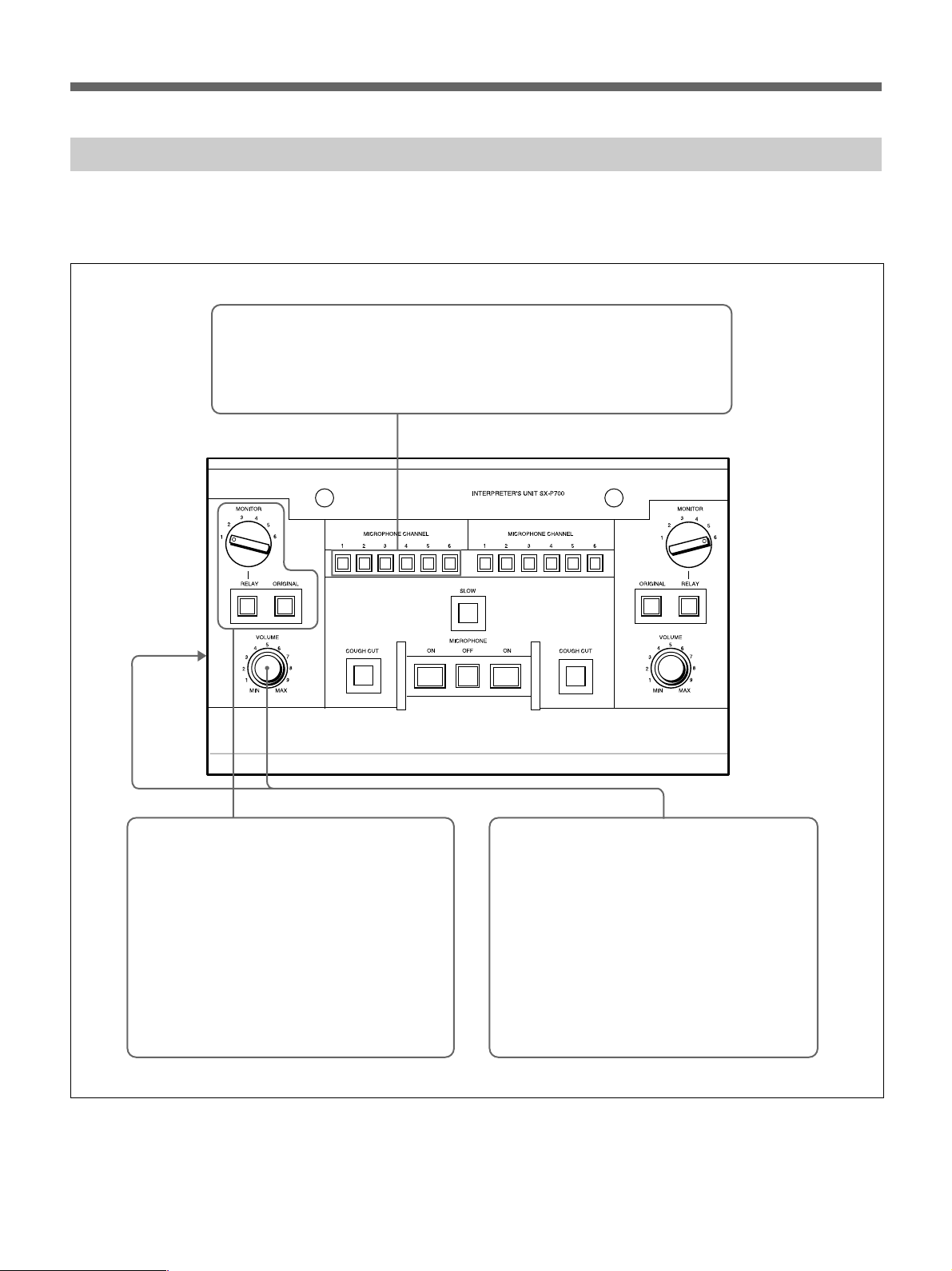
An interpreter uses an SX-P700 interpreter’s unit. The interpreter’s unit is designed to be used simultaneously by
two interpreters.
Confirming the channel of the interpreted language
Confirm that the MICROPHONE CHANNEL button corresponding to the
channel of an interpreter’s target language is lit before the start of the
conference. If the wrong button is lit, press the correct MICROPHONE
CHANNEL button.
Listening to the original signal
Press the ORIGINAL button such that the
ORIGINAL button lights.
When performing the relay interpreting
Set the MONITOR selector to the channel
corresponding to the target language to be
monitored.
To monitor the language selected by the
MONITOR selector, press the RELAY button
such that the RELAY button lights.
Adjusting the headphones volume
To adjust the headphones volume for the
main interpreter
Adjust the main-headphones volume by rotating
the VOLUME control.
To adjust the headphones volume for a subinterpreter
Adjust the sub-headphones volume by rotating
the SUB headphones volume control.
21
Page 22
Operation During a Conference
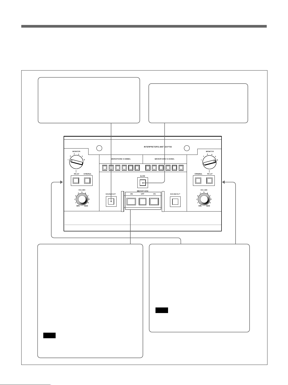
MICROPHONE OFF button and the SLOW button
are common to left and right blocks of the
interpreter’s unit. Either of the two interpreters can
use these buttons.
Temporarily turning off the
microphone (cough cut)
Press the COUGH CUT button. While this
buttons is held down, the interpreter’s
microphone is disabled. Use this button to mask
a cough or sneeze, to talk privately, and so on.
When the speaker speaks too quickly to
interpret
Press the SLOW button. While the SLOW button
is held down, it lights. The chairman is made
aware of the interpreter’s request by the
PRIORITY button blinking.
22
Interpreting
To enable the microphone
Press the MICROPHONE ON button such that the
MICROPHONE ON button and microphone
indicator light. When two interpreters interpret, the
microphone which is currently enabled will be
disabled when the other interpreter presses his or
her MICROPHONE ON button.
To turn off the microphone
Press the MICROPHONE OFF button such that
the MICROPHONE ON button and microphone
indicator go out.
While the microphone is on, the MICROPHONE
ON button and microphone indicator are lit.
Note
The two interpreters cannot press the right and left
MICROPHONE ON buttons at the same time.
Adjusting the microphone level
Set the MIC IN LEVEL switch on the side panel
as follows.
NORM: Usually set the switch to this position.
LOW: Set the switch to this position when a
microphone having a low output level is being
used.
When the interpreter’s voice is weak and low,
set the switch to LOW, regardless of the
microphone output level.
Note
Only the level of the interpreter’s microphone
can be adjusted with this switch.
Page 23

Troubleshooting Guide
Should a problem arise in your system, check the
system while referring to the instructions in the table
below. If the system continues to malfunction after
applying the following checks and remedies, contact
Lighting of the microphone
indicator and MIC ON/OFF
button of the chairman’s
unit/delegate’s unit
The indicator and button blink
for a few seconds when the
POWER switch of the control
unit is set to ON.
The indicator and button of
the chairman’s/delegate’s
units continue to blink, after
the power switch of the control
unit is set to ON.
After the unit has been
operated for a while after the
power is turned on, the unit’s
indicator and button start
blinking and do not go out,
even after a few seconds.
The channel of the language
to be monitored cannot be
selected by the CH selector.
The volume of the earphone
cannot be adjusted by using
the VOL control.
The indicator and button blink
and the microphone is
disabled even if the MIC ON/
OFF button is pressed.
Possible cause
The chairman’s unit/delegate’s
units for a simultaneous
interpretation conference
system, SX-C700A/D700A/
C750/D750, and those for a
conference system, SX-C100A/
D100A/C150/D150, have been
connected.
The units whose indicator and
button are blinking cannot be
controlled by the control unit
and cannot be used in this
system.
A communication error has
occurred.
The earphone may be
disconnected.
The earphone may be
disconnected.
• The mode is that where the
number of speakers is limited.
• The PRIORITY button is held
down by the chairman.
your nearest Sony dealer.
The system indicates the problem by lighting the
microphone indicator and MIC ON/OFF button of
chairman’s/delegate’s units.
Remedies
To configure the simultaneous conference system, use only
SX-C700A/D700A/C750/D750 units.
• When the indicator and button of units subsequent to the
16th unit of the units connected to one DELEGATE’S/
CHAIRMAN’S connector of the control unit blink:
– More than 16 units cannot be connected to one
DELEGATE’S/CHAIRMAN’S connector in series.
Disconnect the 16th unit and subsequent units.
• Even though the number of connected units is less than
16, the indicators of some of the connected units blink:
– The first unit whose indicator and button are blinking
may be defective, or the connecting cable may be
broken.
Disconnect the first unit of those whose indicator and
button are blinking. When the indicator and button of the
subsequent units stop blinking and go out, it indicates
that the disconnected unit was defective. Remove it
from the system or replace it with a functioning unit.
When the indicator and button continue to blink even
after removing the first unit, the connecting cable is
probably broken. Replace the connecting cable linking
the first unit whose indicator and button are blinking and
the unit immediately prior to that unit.
• Even though the number of connected units is less than
16, the indicator and button of some of the connected
units blink:
– The unit whose indicator and button blink is defective.
Disconnect it from the system or replace it with a
functioning unit.
Briefly turn the power off, then back on again.
If the unit subsequently operates normally, communication
is resumed.
If this problem occurs frequently, contact your nearest Sony
dealer.
If the indicator and button continue to blink just after the
power is turned on again, a problem described above may
have occurred. Proceed as described above.
Insert the earphone plug into the earphone jack surely.
Insert the earphone plug into the earphone jack surely.
• Wait until the speaker finishes speaking. Press the MIC
ON/OFF button again.
• Wait until the chairman releases the PRIORITY button.
23
Page 24

Specifications
Design and specifications are subject to change
without notice.
SX-M700A Control Unit
Input/output DELEGATE’S /CHAIRMAN’S
UNIT (20-pin multi-connector)
×4
INTERPRETER’S UNIT (20-pin
multi-connector) ×2
TELEPHONE COUPLER (6-pin
multi connector ) ×1
Input EXT IN-1/EXT IN-2
MIC (XLR 3-pin connector) ×1
Balanced type, input level 0.77
mV (–60 dBs
a)
), for microphone
having low impedance
a) 0 dBs = 0.775 V
MIC (phone jack) ×1
Unbalanced type, input level
0.77 mV (–60 dBs), for
microphone having low
impedance
LINE (phono jack) ×2
Unbalanced type, input level
250 mV (–10 dBs), input
impedance 10 kilohms
AUDIO IN (phono jack) ×1
Input level 250 mV (–10 dBs),
input impedance 10 kilohms
AC IN (3-pin) ×1 for AC power
input
Output LINE OUT ORG/CH1 to CH6
(phono jack) ×7 for each line
Output level 250 mV (–10 dBs),
load impedance 10 kilohms
PHONES (stereo phone jack) ×1
AUDIO OUT (phono jack) ×1
Output level 250 mV (–10 dBs),
load impedance 10 kilohms
Power requirements
100 - 240 V, 50/60Hz
Power consumption
1.2 - 0.5 A
Dimensions 424 × 98 × 388.6 mm (w/h/d)
3
(16
⁄4 × 3 7⁄8 × 15 3⁄8 inches)
Mass 6.2 kg (13 lb 10 oz)
Accessories supplied
AC power cord (1)
Operating instructions (1)
SX-C700A/C750 Chairman’s Unit
SX-D700A/D750 Delegate’s Unit
Input/Output Voting connector (6-pin) ×1
Input Input connector (for SX-C750/
D750 only) (D-sub 15-pin) ×1
Output Earphone output (minijack) ×2
REC OUT (minijack) ×1
Output level 125 mV (–16 dBs),
load impedance 47 kilohms
Microphone line
Output level 250 mV (–10 dBs)
Power requirements
24 V DC
Power consumption
45 mA
Dimensions SX-C700A/D700A :
134 × 401 × 152 mm (w/h/d)
3
(6
⁄4 × 15 7⁄8 × 6 inches)
SX-C750/D750
245 × 372.5
(w/h/d) (9
b)This does not include the part under the
desk. The part under the desk is 40mm.
b)
× 100 mm
3
⁄4 × 14 3⁄4 × 4 inches)
Mass SX-C700A/D700A: 0.7 kg
(1 lb 9 oz)
SX-C750/D750: 0.65 kg (1 lb 7 oz)
SX-P700 Interpreter’s Unit
Input/output CONTROL UNIT/
INTERPRETER’S UNIT
(20-pin multi connector) ×2
Input MIC IN (XLR 3-pin) ×2
Balanced and unbalanced type,
input level 0.77/0.24 mV
(–60 dBs/–70 dBs) selectable
Output LINE OUT (phono jack) ×1
Output level 250 mV (–10 dBs),
output for speaker
MAIN/SUB (stereo phone jack) ×4
–26 dBs/8 ohms with the
maximum output level,
–16 dBs with the maximum
volume setting
Power requirements
24 V DC
Power consumption
40 mA
Dimensions 346.5 × 78.3 × 207.5 mm (w/h/d)
3
(13
⁄4 × 3 1⁄8 × 8 1⁄4 inches)
Mass 1.5 kg (3 lb 4 oz)
Sony Corporation Printed in Japan
 Loading...