

Page 1

Page 2

Page 3
Thank you for purchasing this product.
To Customers
Sufficient expertise is required for installing this product. Be sure to
subcontract the installation to Sony dealers or contractors and pay special
attention to safety during the installation. Sony is not liable for any damages or
injury caused by mishandling or improper installation.
WARNING
If the safety precautions are not observed or the product is used incorrectly, it may
result in serious injury or fire.
US
This instruction manual shows the correct handling of the product and important
precautions necessary to prevent accidents. Be sure to read this manual thoroughly
and use the product correctly. Keep this manual available for future reference.
For Sony dealers
Sufficient expertise is required for installing this product. Be sure to read this
instruction manual thoroughly to do the installation work safely. Sony is not liable
for any damages or injury caused by mishandling or improper installation. Please
instruct the customer to retain this manual for future use.
Page 4
On Safety
Sony products are designed with safety in mind.
If the products are used incorrectly, however, it may
result in a serious situation like fire, electric shock, the
product toppling over, or the product dropping. Be
sure to observe the precautions for safety to prevent
such accidents.
For Customers
WARNING
If the following precautions are not observed,
serious injury or death through fire, electric
shock, the product toppling over, or the product
dropping can result.
Be sure to subcontract the
installation to qualified contractors
and keep small children away during
the installation.
If the Wall-Mount Bracket or the
Display Unit is not installed
correctly, the following
accidents may occur. Be sure to
have qualified contractors carry
out installation.
• The Display Unit may fall and cause a bruise or
serious injury such as a fracture.
• If the wall on which the Wall-Mount Bracket is
installed is unstable, uneven, or not perpendicular to
the floor, the unit may fall and cause injury or
property damage. The wall should be able to
support a weight of at least four times the Display
Unit weight. (See the Display installing dimensions
table on page 11 for the Display Unit weight.)
• If the installation of the Wall-Mount Bracket on the
wall is not sufficiently sturdy, the unit may fall and
cause injury or property damage.
Be sure to subcontract moving or
dismounting of the Display Unit to
qualified contractors.
If persons other than qualified contractors transport or
dismount the Display Unit, it may fall and cause injury
or property damage. Be sure to have two or more
persons carry or dismount the Display Unit.
Do not remove screws, etc., after
mounting the Display Unit.
If you do so, the Display Unit may fall and cause injury
or property damage.
Do not disassemble or make
alterations to the Wall-Mount
Bracket.
If you do so, the Wall-Mount
Bracket may fall and cause
injury or property damage.
Do not mount any equipment other
than the specified product.
This Wall-Mount Bracket is designed for the use with
the specified product only. If you mount equipment
other than specified, it may fall or break, and cause
injury or property damage.
Do not cover the ventilation holes of
the Display Unit.
If you cover the ventilation
holes (with a cloth, etc.), heat
build up inside may cause fire.
Do not apply any load other than
the Display Unit on the Wall-Mount
Bracket.
If you do so, the Display Unit
may fall and cause injury or
property damage.
Do not lean on or hang from the
Display Unit.
Do not lean on or hang from the
Display Unit as it may fall on
you and cause serious injury.
Do not expose the Display Unit to
rain or moisture.
It may cause a fire or an electric shock.
2 (US)
Page 5
Do not spill liquid of any kind on the
Display Unit.
If you allow the Display Unit to
get wet, this may result in a fire
or an electric shock.
Never place the Display Unit in hot,
humid or excessively dusty places, or
in a place where the unit is subjected
to mechanical vibrations.
If you do so, it may cause a fire
or an electric shock.
Keep flammable objects or open
flames (e.g., candles) away from the
Display Unit.
To prevent a fire, keep flammable objects or open
flames (e.g., candles) away from the Display Unit.
CAUTION
If the following precautions are not observed,
injury or property damage may occur.
Do not install the Wall-Mount
Bracket on wall surfaces where the
corners or the sides of the Display
Unit protrude away from the wall
surface.
Do not install the Wall-Mount
Bracket on wall surfaces such as
a pillar, where the corners or the
sides of the Display Unit
protrude away from the wall
surface. If a person or object
happens to hit the protruded
corner or side of the Display
Unit, it may cause injury or
property damage.
Do not handle the product with
excessive force during cleaning or
maintenance.
Do not apply excessive force on the topside of the
Display Unit. If you do so, the Display Unit may fall
and cause injury or property damage.
US
Notes on Use
• If you use the Display Unit installed on the WallMount Bracket for a long time, the wall behind or
above the Display Unit may become discolored or
the wallpaper may peel off, depending on the
material of the wall.
• If the Wall-Mount Bracket is removed after
installation, the screw holes are left.
3 (US)
Page 6
Install the Wall-Mount
Bracket
WARNING
To Customers
Sufficient expertise is required for installing this
product. Be sure to subcontract the installation to
Sony dealers or contractors and pay special
attention to safety during the installation. Sony is
not liable for any damages or injury caused by
mishandling or improper installation.
To Sony Dealers
The following instructions are for Sony Dealers
only. Be sure to read safety precautions described
on the previous pages and pay special attention to
safety during the installation, maintenance and
checking of this product.
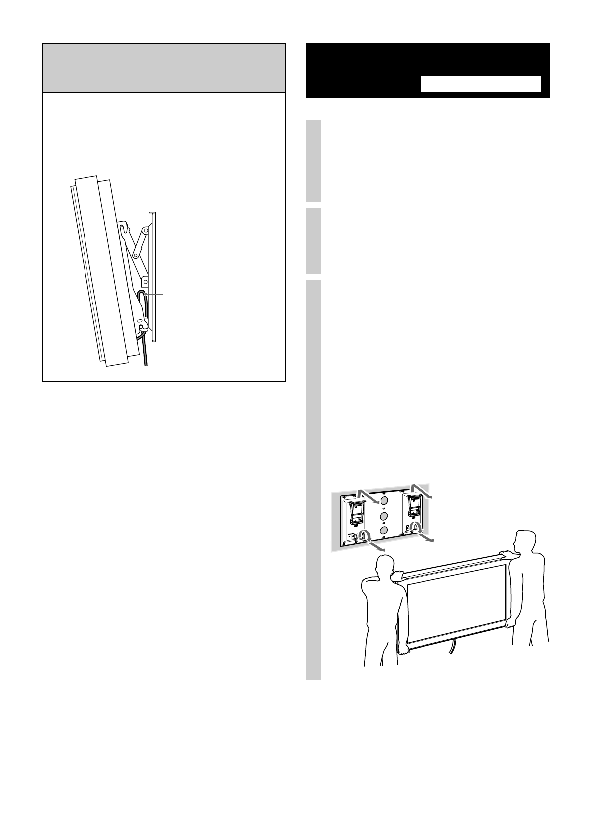
Be sure that two or more persons do
the installation work.
Be sure that two or more
persons install the Display Unit
on the Wall-Mount Bracket. If
one person does the installation
work alone, it may cause back
injury or other injury.
Be sure to install the Wall-Mount
Bracket securely to the wall by
following the instructions in this
instruction manual.
If any of the screws are loose or
fall out, the Wall-Mount Bracket
may fall and cause injury or
property damage. Be sure to use
the appropriate screws for the
material of the wall and install
the unit securely, using at least
six M8 (or equivalent) screws.
For Sony Dealers
Be sure to tighten the screws
securely in the designated position.
If you fail to do so, the Display Unit may fall, and
cause bodily injury to someone or damage to the
Display Unit.
Be careful not to subject the Display
Unit to shock during installation.
If the Display Unit is exposed to shock, it may fall or
break apart. This may cause injury.
Be sure to install the Display Unit on
a wall that is both perpendicular and
flat.
If you fail to do so, the Display Unit may fall and cause
injury.
After proper installation of the
Display Unit, secure the cables
properly.
If people or objects get tangled with cables, this may
result in injury or damage to the Display Unit.
Do not allow the AC power cord or
the display interface cable to be
pinched.
If the AC power cord or the
display interface cable is
pinched between the unit and
the wall or is bent or twisted by
force, the internal conductors
may become exposed and cause
a short circuit or an electrical
break. This may cause a fire or
an electric shock.
Be careful not to hurt your hands or
fingers during the installation.
Be careful not to hurt your hands or fingers when
installing the Wall-Mount Bracket or the Display Unit.
Be sure to use the supplied screws
and attachment parts properly by
following the instructions given in
this instruction manual. If you use
substitute items, the Display Unit
may fall, and cause bodily injury to
someone or damage to the Display
Unit.
4 (US)
The screws needed to secure the
Wall-Mount Bracket to the wall are
not supplied.
You will need to supply the appropriate screws for the
wall material and structure when mounting the WallMount Bracket.
Page 7
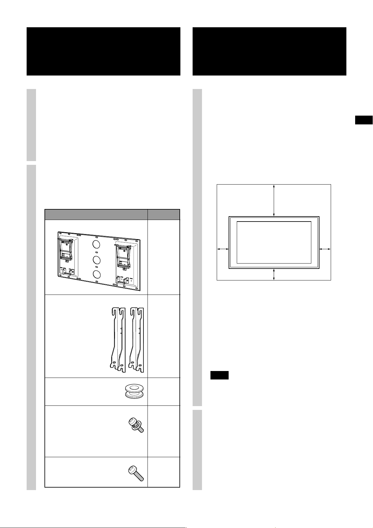
Step 1: Check the parts
Step 2: Decide on the
required for the
installation
1 Before you get started, have on
hand a Phillips screwdriver and
the appropriate screws (at least
six M8 (or equivalent) screws,
not supplied), depending on the
material of the wall.
2 Open the package and check the
parts.
Supplied accessories
Name Quantity
Plate Unit
installation
location
1 Decide on the installation
location. The installation
location should be a
perpendicular and flat wall.
Display dimensions are shown on page 11.
Allow for suitable clearance between the Display
Unit and the ceiling and protruding parts of the
wall as shown below.
Unit: mm (inches)
300
(11 7/8)
US
Mounting Hook Unit
Hook
Screw
M5 × L16
• For hook attachment (4)
• For securing mounting
hook unit (2)
Mounting Hook Unit
Securing Screw 2
M6 × L20
100
1
2
4
(4)
(4)
100
WARNING
The wall that the Display Unit will be installed on
should be able to support a weight of at least four
times that of the Display Unit (page 11).
Determine the supportable weight of the wall
before installing the Display Unit. If the wall
cannot support the weight of the Display Unit,
reinforce as necessary.
Note
If you intend to route the cables behind a wall, make a
hole in the wall to insert the cables. The positions for
the cable holes are shown in the diagram on page 12.
100
(4)
2 Determine the positions of the
6
screws and the cable hole (if you
intend to route the cables
behind the wall) by referring to
the diagram on page 12.
5 (US)
Page 8
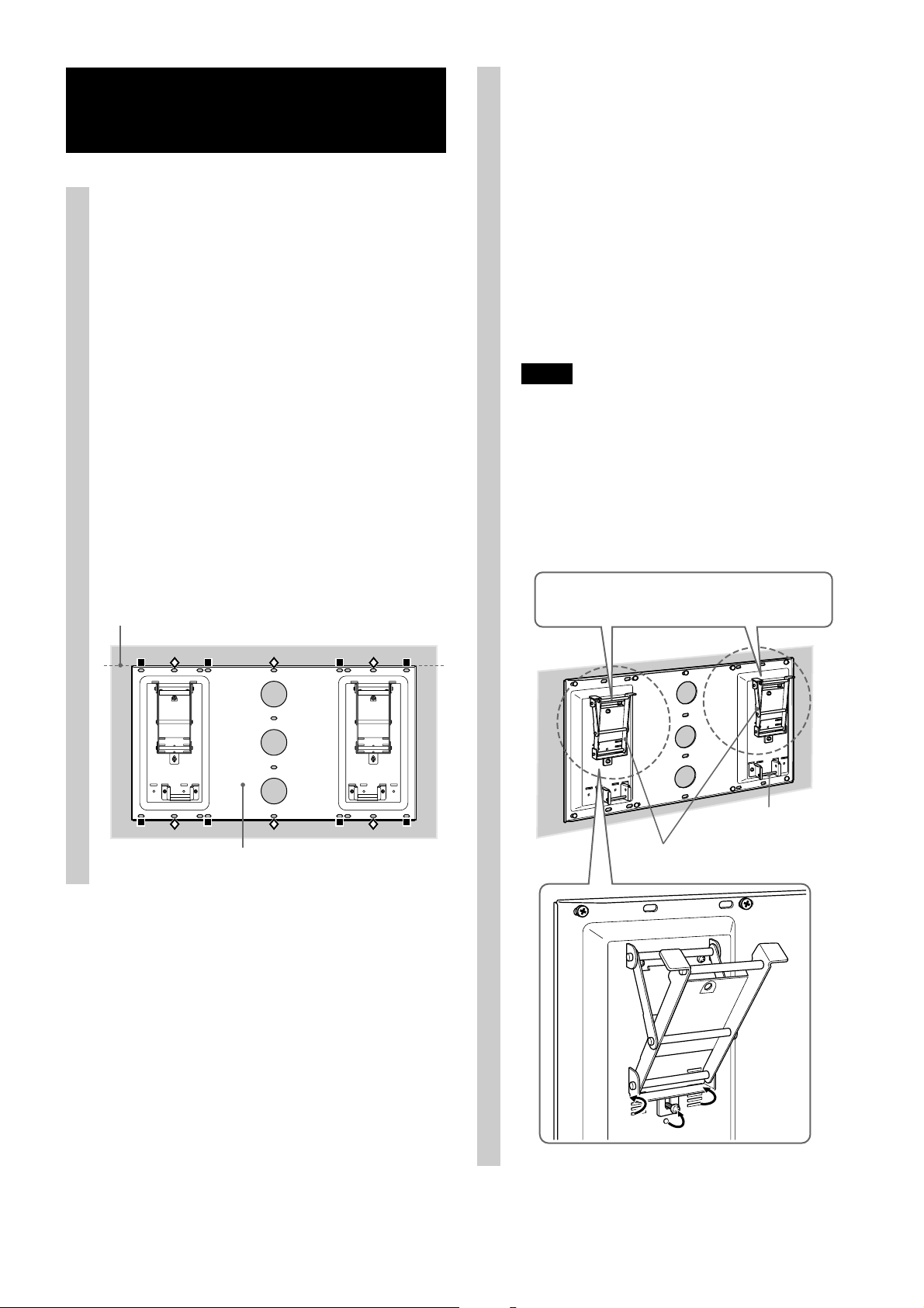
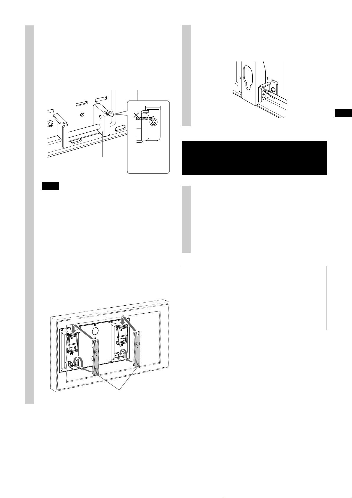
Step 3: Install the Plate
Unit on the wall
1 Attach the Plate Unit to the wall
using at least six M8 (or
equivalent) screws (not
supplied).
Select at least six screw holes with the same
mark shown in the diagram below, and tighten
the screws securely so that they will not come
loose.
WARNING
• The screws securing the Wall-Mount Bracket
to the wall are not supplied. Be sure to use
the appropriate screws, depending on the
material and structure of the wall.
• If the Plate Unit cannot be attached securely
enough, use additional screws.
• Be sure to confirm that the Plate Unit is
securely attached to the wall.
Align the unit so that it is exactly level.
2 Adjust the angle of the arms.
When installing the Display Unit
perpendicularly (0 degrees), adjustment of the
arms angle (Procedure 1 and 2 below) is not
necessary. Make sure that each arm base is
screwed in securely.
1 Remove the screws from the top and bottom
center of the both arm bases. Then choose the
notch corresponding to the desired angle
(5, 10, 15 or 20 degrees) and fit the arm base
to it.
2 Firmly secure each arm base using the screws
removed in the above procedure 1.
Notes
• Be sure to adjust the angle of both left and right
arms to the same angle.
• Be careful not to get your fingers caught when
adjusting the angle of the arms.
• When using an electric screwdriver, set the torque
setting to approximately 2 N·m.
• Make sure that the two Mounting Hook Unit
support shafts on the lower part of the Plate Unit
are screwed in securely.
•0 degrees: Leave the white screws tightened as
they are.
• Other than 0 degrees: Remove the white screws.
6 (US)
Plate Unit
1
Mounting Hook Unit
Support Shaft
Arm Base
2
Page 9
Step 4: Prepare for the
installation of
the Display Unit
2 Attach the supplied four hooks with the four
supplied screws (M5 × L16).
Attach the hooks for fixing the
Mounting Hook Units to the
Display Unit.
1 Place the Display Unit, with its screen facing
down, on a stable, cloth-covered work
surface.
Note
The Display Unit should be handled by at least two
people.
Rear side of Display Unit
Soft cloth
Screw (supplied M5 × L16)
Hook
(supplied)
Note
When using an electric screwdriver, set the torque
setting to approximately 2 N·m.
US
Bottom of Display Unit
This Display
Unit has finger
slots on both
sides at the
bottom for
holding.
z Hint
There are finger slots located at the bottom of the
Display Unit on both sides for holding. When
installing the Display Unit, use the slot to support the
bottom and hold the top with your other hand.
7 (US)
Page 10
Step 5: Install the
Display Unit
2 Connect the AC power cord and
the display interface cable
supplied with the Display Unit
to the Display Unit.
WARNING
Be sure to complete the installation before
connecting the AC power cord to the wall outlet. If
you allow the AC power cord to be pinched under
or between pieces of equipment, this may result in
a short circuit or an electric shock.
Be careful not to stumble over the AC power cord
or the Display Unit, as you may hurt yourself.
1 Attach the Mounting Hook Unit
on the hooks on the rear side of
the Display Unit. Then slide the
Mounting Hook Unit, as
illustrated below, and fix it
using the supplied screws (M5 ×
L16).
Mounting Hook Unit
Screw (supplied M5 × L16)
Connect the AC power cord and the display
interface cable to the connectors on the rear side
of the Display Unit. For details on connecting
the AC power cord and the display interface
cable, refer to the Operating Instructions
supplied with the Display Unit.
When you route the cable and the cord behind
the wall, feed them through the hole you drilled
(page 12).
Notes
• Once you install the Display Unit to the Plate Unit,
you cannot connect the cord and the cables.
• Be sure to subcontract the routing of the cable
behind the wall and electrical work to qualified
contractors.
Soft cloth Rear side of Display Unit
Thread the cable through here.
8 (US)
Page 11
3 Install the Display Unit on the
Plate Unit.
1 Insert the screws (M6 × L20, supplied) into
the screw holes on the outer left and right
sides of the Mounting Hook Unit support
shafts, and tighten them temporarily.
Tighten the
screws to halfway
Mounting Hook Unit
Support Shaft
so that they do
not protrude from
the opposite side.
5 Confirm the eight hooks are firmly hooked
on the four shafts on the Plate Unit.
6 Firmly tighten the securing screws that you
screwed in temporarily in Procedure 1.
US
Confirm the completion of the installation
Note
If the temporarily attached screws protrude inside the
Mounting Hook Unit support shafts, they will get in
the way of Mounting Hook Units being fitted in place
(procedure 4).
2 Attach the upper hooks of the two Mounting
Hook Units to the support shafts of the arms.
3 Place the lower hooks of the two Mounting
Hook Units so that they touch the front side
of the Mounting Hook Unit support shafts.
4 Slightly push the Display Unit toward the
Plate Unit and upward to attach the lower
hooks of the two Mounting Hook Units to the
Mounting Hook Unit support shafts.
2
4
Check the following points.
• Eight hooks of the Mounting Hook Units are
firmly hooked on to the four shafts on the
Plate Unit.
• The cord and the cable are not twisted or
pinched.
• The two securing screws are securely
tightened on the Mounting Hook Unit.
WARNING
Incomplete installation may cause the product to
fall and result in injury or product damage. Also,
improper placement of the AC power cord, etc.,
may cause fire or electric shock through a short
circuit.
Be sure to confirm the completion of the
installation for safety.
3
Mounting Hook Unit
9 (US)
Page 12
Note on connecting the display interface cable
VMC-X10 (not supplied) without using the cable
hole of the Plate Unit
When connecting the display interface cable VMCX10 (not supplied), leave some upward slack in the
cable to avoid stressing it. Otherwise, the connector
may become loose and the picture may not appear
on the screen, or the Display Unit will not turn on.
Remove the Display Unit
For Sony Dealers
1 Disconnect the AC power cord
and the display interface cable
from the wall outlet and the
Display Unit.
2 Remove the two securing screws
on the right and left Mounting
Hook Unit support shafts.
Leave some upward slack
in the cable.
3 Be sure to have two or more
persons hold the Display Unit
and slide it upward to remove
the Display Unit.
WARNING
• Be sure to have two or more persons hold the
Display Unit when carrying it.
• Be careful not to allow the cord and cables to
get hung up when removing the Display
Unit.
• Be careful not to hurt your hands or fingers
when removing the Display Unit.
10 (US)
Page 13

Unit specifications
Unit: mm (inches)
Weight: 11.5 kg (25 lb 6 oz)
Plate Unit
467.6
(18 1/2)
870 (34 3/8)
66
(2 5/8)
Display installing dimensions table
A
Mounting Hook Unit
US
385
(15 1/4)
51
(2 1/8)
F
C
B
B
D
441
(17 3/8)
E
Display Model
KDX-46Q005 1239 717 130 281 80
(XDM-F4600Q)
* The wall that the Display Unit will be installed on should be able to support a weight of at least four times that of the Display Unit.
Display Dimensions Unit: mm (inches) Length for each mounting angle Unit: mm (inches) Weight
ABCDE
(48 7/8) (28 1/4) (5 1/8) (11 1/8) (3 1/4)
Mounting
angle (αº)
0º 204 (8 1/8) 195 (7 3/4) 80 (3 1/4)
5º 252 (10) 188 (7 1/2) 92 (3 5/8)
10º 299 (11 7/8) 175 (7) 102 (4 1/8)
15º 344 (13 5/8) 159 (6 3/8) 111 (4 3/8)
20º 392 (15 1/2) 137 (5 1/2) 121 (4 7/8)
FGHWeight (× 4)*
130lb 2oz 520lb 5oz
59kg 236kg
G
H
11 (US)
Page 14

Wall processing dimensions diagram
Unit: mm (inches)
870 (34 3/8)
812 (32)
610 (24 1/8)
455 (18)
467.6
(18 1/2)
220.5
13.3
(17/32)
(8 3/4)
73.5
13.3
(3)
(17/32)
ø 60 (2 23/64)
Hole for cable routing
406 (16)
20 - 9 × 20 (23/64 × 5/6)
Slot hole
147
147
441
(5 7/8)
(5 7/8)
(17 3/8)
12 (US)
Page 15

Nous vous remercions d’avoir fait l’acquisition de ce produit.
À l’attention des clients
Une certaine expérience est requise pour installer ce produit. Confiez
l’installation à un détaillant Sony ou à un autre professionnel et portez une
attention particulière aux consignes de sécurité pendant l’installation. Sony ne
saurait être tenue responsable de tout dommage ou de toute blessure découlant
d’une mauvaise utilisation ou d’une installation incorrecte.
AVERTISSEMENT
Le non-respect des consignes de sécurité ou l’utilisation incorrecte de ce produit
peut provoquer un incendie ou des blessures graves.
Ce mode d’emploi indique comment manipuler le produit correctement et contient
des précautions essentielles à prendre pour éviter tout accident. Lisez
attentivement ce mode d’emploi et veillez à utiliser le produit correctement.
Conservez ce mode d’emploi pour toute référence ultérieure.
À l’attention des détaillants Sony
Une certaine expérience est requise pour installer ce produit. Lisez ce mode
d’emploi attentivement afin de procéder à l’installation en toute sécurité. Sony ne
saurait être tenue responsable de tout dommage ou de toute blessure découlant
d’une mauvaise utilisation ou d’une installation incorrecte. Veuillez indiquer au
client de conserver ce manuel pour pouvoir s’y référer ultérieurement.
FR
Page 16

Sécurité
Les produits Sony sont conçus pour vous offrir le
maximum de sécurité. Toutefois, si les produits sont
utilisés de façon incorrecte, ils peuvent entraîner des
blessures graves en provoquant un incendie ou une
électrocution, ou la chute de l’appareil hors de son
support. Veillez à observer les consignes de sécurité
préconisées pour éviter de tels accidents.
À l’attention des clients
Ne retirez pas les vis etc. après
l’installation de l’écran.
Sinon, l’écran risque de tomber et de provoquer des
blessures ou des dommages matériels.
Ne démontez pas et ne modifiez pas
le support de fixation mural.
Sinon, le support de fixation
mural risque de tomber et de
provoquer des blessures ou des
dommages matériels.
AVERTISSEMENT
Le non-respect des consignes suivantes peut
être fatal ou entraîner des blessures graves en
provoquant un incendie ou une électrocution,
ou la chute de l’appareil hors de son support.
Confiez l’installation à des
professionnels qualifiés et tenez les
enfants à l’écart pendant
l’installation.
Si le support de fixation mural
ou l’écran n’est pas installé
correctement, les accidents
suivants peuvent se produire.
Confiez l’installation à des
professionnels qualifiés.
•L’écran peut tomber et causer des blessures graves
comme des hématomes ou des fractures.
• Si le mur sur lequel le support de fixation mural est
fixé est instable, inégal ou non perpendiculaire au
sol, l’appareil risque de tomber et de provoquer des
blessures ou des dommages matériels. Le mur doit
pouvoir supporter un poids équivalent à au moins
quatre fois le poids de l’écran (reportez-vous au
tableau des dimensions d’installation de l’écran à la
page 11 pour connaître le poids de l’écran).
• Si l’installation du support de fixation mural n’est
pas assez solide, l’appareil risque de tomber et de
provoquer des blessures ou des dommages
matériels.
Confiez le déplacement ou le
démontage de l’écran à des
professionnels qualifiés.
Si des personnes autres que des professionnels
qualifiés transportent ou démontent l’écran, celui-ci
peut tomber et provoquer des blessures ou des
dommages matériels. Deux personnes au moins
doivent porter ou démonter l’écran.
N’installez aucun appareil autre que
ceux spécifiés.
Ce support de fixation mural est conçu pour être utilisé
avec le produit spécifié uniquement. Si vous installez
un équipement autre que ceux qui sont spécifiés, il
pourrait tomber ou se briser et provoquer des blessures
ou des dommages matériels.
Ne bouchez pas les orifices de
ventilation de l’écran.
Si vous couvrez les orifices de
ventilation (avec du tissu ou un
autre matériau), l’appareil
pourrait surchauffer et
provoquer un incendie.
N’installez aucune charge autre que
l’écran sur le support de fixation
mural.
Dans le cas contraire, l’écran
risque de tomber et de
provoquer des blessures ou des
dommages matériels.
Ne vous appuyez pas sur l’écran ou
ne vous y suspendez pas.
Ne vous appuyez pas sur
l’écran ou ne vous y suspendez
pas car il risque de tomber et de
causer des blessures graves.
N’exposez pas l’écran à la pluie ou à
l’humidité.
Dans ce cas, un incendie ou une électrocution pourrait
se produire.
2 (FR)
Page 17

Ne renversez aucun liquide sur
l’écran.
Si l’écran est mouillé, un
incendie ou une électrocution
pourrait se produire.
N’installez jamais l’écran dans des
endroits chauds, humides ou
extrêmement poussiéreux, ou dans
des endroits où l’appareil serait
soumis à des vibrations mécaniques.
Dans ce cas, un incendie ou une
électrocution pourrait se
produire.
Conservez l’écran hors de portée des
objets inflammables ou des corps
incandescents (par exemple des
bougies).
Pour éviter un incendie, ne laissez pas d’objets
inflammables ou de corps incandescents (par exemple
des bougies) à proximité de l’écran.
ATTENTION
Le non-respect des consignes suivantes peut
entraîner des blessures ou des dommages
matériels.
N’installez pas le support de fixation
mural sur des surfaces murales où les
coins ou les côtés de l’écran
dépasseraient.
N’installez pas le support de
fixation mural sur des surfaces
murales comme des colonnes
où les coins ou les côtés de
l’écran dépasseraient de la
surface murale. Si une personne
ou un objet venait à heurter le
coin ou les côtés de l’écran, ceci
risquerait de provoquer des
blessures ou des dommages
matériels.
N’appliquez aucune force excessive
sur le produit au cours de l’entretien
ou du nettoyage de l’appareil.
N’exercez aucune pression excessive sur le dessus de
l’écran. Dans le cas contraire, l’écran risque de tomber et
de provoquer des blessures ou des dommages matériels.
FR
Remarques à propos de l’utilisation
• Si vous utilisez l’écran fixé au support de fixation
mural pendant une longue période, le mur situé
derrière ou au-dessus de l’écran peut se décolorer ou
le papier peut se décoller selon le matériau du mur.
• Les trous des vis restent apparents si vous démontez
le support de fixation mural après son installation.
3 (FR)
Page 18

Installation du support
de fixation mural
Veillez à serrer les vis solidement
dans la position indiquée.
Sinon, l’écran risque de tomber et de causer des
blessures corporelles ou d’être endommagé.
À l’attention des
détaillants Sony
AVERTISSEMENT
À l’attention des clients
Une certaine expérience est requise pour installer
ce produit. Confiez l’installation à un détaillant
Sony ou à un autre professionnel et portez une
attention particulière aux consignes de sécurité
pendant l’installation. Sony ne saurait être tenue
responsable de tout dommage ou de toute blessure
découlant d’une mauvaise utilisation ou d’une
installation incorrecte.
À l’attention des détaillants Sony
Les instructions suivantes concernent les détaillants
Sony uniquement. Lisez attentivement les consignes
de sécurité des pages précédentes et accordez une
attention particulière à la sécurité lors de l’installation,
de l’entretien et de la vérification de ce produit.
Le travail d’installation doit être
effectué par au moins deux
personnes.
Veillez à ce qu’au moins deux
personnes installent l’écran sur
le support de fixation mural. Le
travail d’installation réalisé par
une seule personne risque de
provoquer un accident ou des
blessures.
Veillez à installer le support de
fixation mural solidement en suivant
les instructions de ce mode d’emploi.
S’il manque des vis ou si elles
sont desserrées, le support de
fixation mural pourrait tomber
et provoquer des blessures ou
des dommages matériels.
Veillez à utiliser les vis
appropriées selon le matériau
du mur et installez l’appareil solidement en utilisant au
moins six vis M8 (ou équivalentes).
Veillez à utiliser correctement les vis
et les pièces de fixation fournies
conformément aux instructions du
mode d’emploi. Si vous utilisez
d’autres éléments de fixation, l’écran
risque de tomber et de causer des
blessures corporelles ou d’être
endommagé.
Veillez à ne pas faire subir de chocs à
l’écran pendant l’installation.
Si l’écran subit des chocs, il risque de tomber ou de se
casser. Ceci pourrait causer des blessures.
Veillez à installer l’écran sur un mur
perpendiculaire et plat.
Dans le cas contraire, l’écran risque de tomber et de
provoquer des blessures.
Une fois l’écran installé
correctement, fixez solidement les
câbles.
Si des personnes ou des objets se prennent dans les
câbles, ceci risque de provoquer der blessures ou
d’endommager l’écran.
Veillez à ce que le cordon
d’alimentation CA ou le câble
d’interface de l’écran ne soit pas
coincé.
Si le cordon d’alimentation CA
ou le câble d’interface de l’écran
est coincé entre l’appareil et le
mur, ou s’il est plié ou tordu, les
conducteurs internes peuvent
être exposés et provoquer un
court-circuit ou une coupure
électrique. Un incendie ou une
électrocution pourrait en
résulter.
Faites attention afin de ne pas vous
blesser les mains ou les doigts au
cours de l’installation.
Prenez garde à ne pas vous blesser les mains ou les
doigts pendant l’installation du support de fixation
mural ou de l’écran.
Les vis nécessaires à l’installation du
support de fixation mural au mur ne
sont pas fournies.
Vous devrez utiliser les vis appropriées selon le
matériau et la structure du mur lors du montage du
support de fixation mural.
4 (FR)
Page 19

Étape 1 : Vérification des
Étape 2 : Choix de
pièces requises
pour l’installation
1 Avant de commencer, préparez
un tournevis cruciforme et les
vis appropriées (au moins six vis
M8 ou équivalentes, non
fournies), selon le matériau du
mur.
2 Ouvrez l’emballage et vérifiez
les pièces.
Accessoires fournis
Nom Quantité
Plaque
l’emplacement
d’installation
1 Choisissez l’emplacement
d’installation. L’emplacement
d’installation doit être un mur
perpendiculaire et plat.
Les dimensions de l’écran sont indiquées à la
page 11. Laissez un espace suffisant entre l’écran,
le plafond et les pièces dépassant du mur
comme indiqué sur l’illustration de ci-dessous.
Unité : mm (pouces)
300
(11 7/8)
FR
Crochet de fixation
Crochet
Vis
M5 × L16
• Pour la fixation des
crochets (4) 6
• Pour la fixation des
crochets de fixation (2)
Vis de fixation du crochet
de fixation 2
M6 × L20
100
(4)
1
(4)
100
AVERTISSEMENT
Le mur sur lequel l’écran est installé doit
pouvoir supporter un poids équivalent à au
moins quatre fois le poids de l’écran (page 11).
Déterminez la résistance du mur avant
2
4
d’installer l’écran. Si le mur ne peut pas
supporter le poids de l’écran, renforcez-le en
conséquence.
Remarque
Si vous avez l’intention de faire passer les câbles
derrière un mur, percez un trou dans le mur pour y
insérer les câbles. Les positions des trous réservés aux
câbles sont indiquées dans le schéma à la page 12.
100
(4)
2 Déterminez les positions des vis
et du trou pour les câbles (si
vous avez l’intention de faire
passer les câbles derrière le mur)
en vous reportant au schéma à
la page 12.
5 (FR)
Page 20

Étape 3 : Installation de
la plaque sur
le mur
1 Fixez la plaque au mur à l’aide
d’au moins six vis M8 (ou
équivalentes), non fournies.
Choisissez au moins six trous de vis portant la
même marque dans le schéma ci-dessous et
vissez-y solidement les vis afin qu’elles ne se
desserrent pas.
AVERTISSEMENT
• Les vis nécessaires à la fixation du support de
fixation mural au mur ne sont pas fournies.
Veillez à utiliser les vis appropriées selon le
matériau et la structure du mur.
• Si la plaque n’est pas fixée assez solidement,
utilisez des vis supplémentaires.
• Vérifiez que la plaque est fixée solidement au
mur.
Alignez la plaque afin qu’elle soit
parfaitement horizontale.
2 Réglez l’angle des bras.
Le réglage de l’angle des bras (étapes 1 et 2 cidessous) n’est pas nécessaire lors de
l’installation de l’écran en position
perpendiculaire (0 degré). Vérifiez que chaque
support des bras est fixé solidement.
1 Retirez les vis situées dans la partie centrale
supérieure et inférieure des deux supports de
bras. Choisissez le cran d’arrêt correspondant
à l’angle souhaité (5, 10, 15 ou 20 degrés) et
fixez-y le support de bras.
2 Attachez solidement chaque support de bras
à l’aide des vis retirées à l’étape ci-dessus 1.
Remarques
• Veillez à régler l’angle des bras droit et gauche au
même degré d’inclinaison.
• Faites attention à ne pas vous faire pincer les doigts
lors du réglage de l’angle des bras.
• Si vous utilisez une visseuse électrique, réglez le
couple à 2 N·m environ.
•Veillez à ce que les deux arbres-support du crochet
de fixation situés au bas de la plaque soient vissés
correctement.
•0 degré : ne touchez pas aux vis blanches.
• Autre que 0 degré : retirez les vis blanches.
Plaque
Support de bras
1
Arbre-support du
crochet de fixation
2
6 (FR)
Page 21

Étape 4 : Préparation de
l’installation
de l’écran
2 Fixez les quatre crochets fournis avec les
quatre vis fournies (M5 × L16).
Fixez les crochets permettant de
fixer les crochets de fixation sur
l’écran.
1 Installez l’écran tourné vers le bas sur une
surface stable et recouverte d’un drap.
Remarque
La manipulation de l’écran doit être effectuée par au
moins deux personnes.
Arrière de l’écran
Chiffon
doux
Vis (fournies M5 × L16)
Crochet
(fourni)
Remarque
Si vous utilisez une visseuse électrique, réglez le
couple à 2 N·m environ.
FR
Cet écran dispose
de fentes
permettant d’y
glisser les doigts
de chaque côté
de la base pour le
tenir.
z Conseil
Cet écran dispose de fentes permettant d’y glisser les
doigts de chaque côté de la base pour le tenir. Pour
installer l’écran, utilisez l’une des fentes pour
supporter la base et tenez le haut avec l’autre main.
Dessous de l’écran
7 (FR)
Page 22

Étape 5 : Installation de
l’écran
2 Branchez le cordon
d’alimentation CA et le câble
d’interface de l’écran, fourni
avec l’écran, à l’écran.
AVERTISSEMENT
Terminez d’abord l’installation avant de brancher
le cordon d’alimentation CA dans la prise de
courant. Ne laissez pas le cordon d’alimentation
CA se coincer entre des pièces de l’appareil ou sous
l’appareil, ce qui pourrait provoquer un courtcircuit ou une électrocution.
Prenez garde à ne pas trébucher sur le cordon
d’alimentation CA ou à heurter l’écran car vous
pourriez vous blesser.
1 Fixez le crochet de fixation sur
les crochets situés à l’arrière de
l’écran. Faites ensuite glisser le
crochet de fixation, comme
illustré ci-dessous, et fixez-le à
l’aide des vis fournies (M5 ×
L16).
Crochet de fixation
Branchez le cordon d’alimentation CA et le câble
d’interface de l’écran aux connecteurs situés à
l’arrière de l’écran. Consultez le Mode d’emploi
fourni avec l’écran pour obtenir des détails sur la
façon de brancher le cordon d’alimentation CA
et le câble d’interface de l’écran.
Si vous faites passer le câble et le cordon derrière
le mur, faites-les passer par le trou que vous
avez percé (page 12).
Remarques
• Une fois l’écran installé sur la plaque, vous ne
pouvez pas raccorder le cordon et les câbles.
• Confiez le passage des câbles derrière le mur et les
travaux électriques à des professionnels qualifiés.
Vis (fournies M5 × L16)
Chiffon doux Arrière de l’écran
Passez le câble par ici.
8 (FR)
Page 23

3 Installez l’écran sur la plaque.
1 Insérez les vis (M6 × L20, fournies) dans les
trous de vis sur les côtés extérieurs gauche et
droit des arbres-support du crochet de
fixation, puis vissez-les temporairement.
Serrez les vis à
moitié pour
Arbre-support du
crochet de fixation
Remarque
Si les vis serrées temporairement pénètrent à
l’intérieur des arbres-support du crochet de fixation,
elles se trouveront sur le passage des crochets de
fixation mis en place (étape 4).
2 Fixez les crochets supérieurs des deux
crochets de fixation sur les arbres-support
des bras.
3 Placez les crochets inférieurs des deux
crochets de fixation de sorte qu’ils touchent
l’avant des arbres-support du crochet de
fixation.
4 Poussez légèrement l’écran vers la plaque et
vers le haut pour fixer les crochets inférieurs
des deux crochets de fixation sur les arbressupport du crochet de fixation.
2
qu’elles ne
dépassent pas de
l’autre côté.
5 Vérifiez que les huit crochets sont solidement
fixés sur les quatre arbres de la plaque.
6 Serrez à fond les vis vissées temporairement
à l’étape 1.
Vérification de l’installation
Vérifiez les points suivants.
• Vérifiez que les huit crochets du crochet de
fixation sont solidement fixés sur les quatre
arbres de la plaque.
• Le cordon et le câble ne sont pas tordus, ni
coincés.
• Les deux vis de fixation sont solidement
serrées sur le crochet de fixation.
AVERTISSEMENT
Si l’installation est incomplète, le produit pourrait
tomber et provoquer des blessures ou être
endommagé. En outre, si le cordon d’alimentation
CA ou autre n’est pas correctement installé, un
court-circuit pourrait survenir et provoquer un
incendie ou une électrocution.
Pour votre sécurité, vérifiez que l’installation est
effectuée complètement.
FR
4
3
Crochet de fixation
9 (FR)
Page 24

Remarque concernant le raccordement du câble
d’interface de l’écran VMC-X10 (non fourni) sans
utiliser le trou de câble de la plaque
Lors du raccordement du câble d’interface de
l’écran VMC-X10 (non fourni), faites en sorte que la
partie supérieure du câble reste lâche afin d’éviter
toute tension. Dans le cas contraire, le connecteur
risquerait de se déconnecter et l’image pourrait ne
pas apparaître à l’écran ou l’écran pourrait ne pas
se mettre sous tension.
Dépose de l’écran
À l’attention des
détaillants Sony
1 Débranchez le cordon
d’alimentation CA et le câble
d’interface de l’écran de la prise
murale et de l’écran.
2 Retirez les deux vis de fixation à
droite et à gauche des arbressupport du crochet de fixation.
Faites en sorte que la partie
supérieure du câble reste
lâche.
3 Au moins deux personnes
doivent tenir l’écran pour le
faire glisser vers le haut et le
retirer.
AVERTISSEMENT
•Veillez à ce qu’au moins deux personnes
tiennent l’écran lors du transport.
•Prenez garde à ne pas tendre le cordon et les
câbles lors de la dépose de l’écran.
• Faites attention à ne pas vous blesser les
mains ou les doigts pendant la dépose de
l’écran.
10 (FR)
Page 25

Caractéristiques techniques de l’appareil
Unité : mm (pouces)
Poids : 11,5 kg (25 lb 6 oz)
Plaque
870 (34 3/8)
467,6
(18 1/2)
66
(2 5/8)
Crochet de fixation
385
51
(2 1/8)
Tableau des dimensions d’installation de l’écran
A
(15 1/4)
FR
F
B
B
D
441
(17 3/8)
E
Modèle d’écran
KDX-46Q005
(XDM-F4600Q)
* Le mur sur lequel l’écran est installé doit pouvoir supporter un poids équivalent à au moins quatre fois le poids de l’écran.
Dimensions de l’écran Unité : mm (pouces)
A BCDE
1239 717 130 281 80
(48 7/8) (28 1/4) (5 1/8) (11 1/8) (3 1/4)
Longueur de chaque angle de fixation Unité : mm (pouces)
Angle de
fixation (αº)
0º 204 (8 1/8) 195 (7 3/4) 80 (3 1/4)
5º 252 (10) 188 (7 1/2) 92 (3 5/8)
10º 299 (11 7/8) 175 (7) 102 (4 1/8)
15º 344 (13 5/8) 159 (6 3/8) 111 (4 3/8)
20º 392 (15 1/2) 137 (5 1/2) 121 (4 7/8)
FGHPoids (× 4)*
C
G
H
Poids
59kg 236kg
130lb 2oz 520lb 5oz
11 (FR)
Page 26

Schéma des dimensions d’installation au mur
Unité : mm (pouces)
870 (34 3/8)
812 (32)
610 (24 1/8)
455 (18)
467,6
(18 1/2)
220,5
13,3
(17/32)
(8 3/4)
73,5
13,3
(3)
(17/32)
ø 60 (2 23/64)
Trou pour le passage des câbles
406 (16)
20 - 9 × 20 (23/64 × 5/6)
Trou d’encoche
147
147
441
(5 7/8)
(5 7/8)
(17 3/8)
12 (FR)
Page 27

Gracias por comprar este producto.
Información para los clientes
Para instalar este producto, se requieren unos conocimientos técnicos
suficientes. Asegúrese de contratar la instalación a un distribuidor o contratista
de Sony y preste especial atención a la seguridad durante la instalación. Sony
no se responsabiliza de ningún daño o lesión provocada por una manipulación
o instalación incorrectas.
ADVERTENCIA
Si no se siguen las medidas de seguridad o el producto se utiliza incorrectamente,
pueden provocarse lesiones graves o incendios.
Este manual de instrucciones muestra la manera correcta de manipular el
producto, así como precauciones importantes necesarias para evitar accidentes. Lea
este manual atentamente y utilice el producto correctamente. Conserve este
manual para consultarlo en el futuro.
Información para los distribuidores de Sony
Para instalar este producto, se requieren unos conocimientos técnicos suficientes.
Lea este manual de instrucciones atentamente para realizar la instalación de
manera segura. Sony no se responsabiliza de ningún daño o lesión provocada por
una manipulación o instalación incorrectas. Pida al cliente que conserve este
manual para consultarlo en el futuro.
ES
Page 28

Sobre la seguridad
Los productos Sony se diseñaron pensando en la
seguridad. Sin embargo, si los productos se utilizan
incorrectamente, pueden provocar situaciones
peligrosas como un incendio, una descarga eléctrica,
que el producto vuelque o que se caiga. Para evitar
tales accidentes, asegúrese de cumplir las precauciones
de seguridad.
Información para los clientes
No retire tornillos, etc., una vez
montado el monitor.
Si lo hace, el monitor puede caerse y provocar daños
personales o materiales.
No desmonte ni modifique el
soporte de montaje mural.
Si lo hace, el soporte de montaje
mural puede caerse y provocar
daños personales o materiales.
ADVERTENCIA
Si no se tienen en cuenta las precauciones
siguientes, pueden provocarse lesiones graves o
incluso la muerte a raíz de un incendio, una
descarga eléctrica o tras volcar o caerse el
producto.
Asegúrese de contratar la instalación
a contratistas cualificados y
mantenga a los niños alejados
durante la instalación.
Si el soporte de montaje mural o
el monitor no están instalados
correctamente, se pueden
producir los accidentes
siguientes. Asegúrese de que la
instalación la realizan
contratistas cualificados.
• El monitor puede caerse y provocar contusiones o
lesiones graves como fracturas.
• Si la pared en la que se instala el soporte de montaje
mural es inestable, desigual o no es perpendicular
con el piso, la unidad puede caerse y provocar daños
personales o materiales. La pared debe ser capaz de
soportar un peso de al menos cuatro veces el peso
del monitor. (Consulte la tabla de dimensiones de
instalación del monitor en la página 11 para conocer
el peso del monitor.)
• Si la instalación del soporte de montaje mural no es
suficientemente resistente, es posible que la unidad
caiga y provoque daños personales o materiales.
Asegúrese de contratar el traslado o
el desmontaje del monitor a
contratistas cualificados.
Si otras personas que no son contratistas cualificados
transportan o desmontan el monitor, éste puede caerse
y provocar daños personales y materiales. Asegúrese
de que al menos dos o más personas transportan o
desmontan el monitor.
No monte ningún otro equipo que
no sea el producto especificado.
Este soporte de montaje mural se diseñó para utilizarse
sólo con el producto especificado. Si monta un equipo
distinto del especificado, puede caerse o quebrarse y
provocar daños personales o materiales.
No obstruya los orificios de
ventilación del monitor.
Si cubre los orificios de
ventilación (con un paño, etc.),
el monitor podría
sobrecalentarse y provocar un
incendio.
No aplique ningún peso que no sea
el del propio monitor en el soporte
de montaje mural.
Si lo hace, el monitor puede
caerse y provocar daños
personales o materiales.
No se apoye en el monitor ni se
agarre a él.
No se apoye en el monitor ni se
agarre a él, ya que puede caerle
encima y provocarle lesiones
graves.
No exponga el monitor a la lluvia ni
a la humedad.
Puede originarse un incendio o una descarga eléctrica.
2 (ES)
Page 29

No vierta ningún tipo de líquido
sobre el monitor.
Si el monitor se moja, puede
provocarse un incendio o una
descarga eléctrica.
No coloque nunca el monitor en
lugares cálidos, húmedos o
excesivamente polvorientos ni en
lugares en los que se produzcan
vibraciones.
Si lo hace, puede originarse un
incendio o una descarga
eléctrica.
Mantenga el monitor alejado de
objetos inflamables y de fuegos
desprotegidos (por ejemplo, velas).
Para evitar un incendio, mantenga el monitor alejado
de objetos inflamables y de fuegos desprotegidos (por
ejemplo, velas).
PRECAUCIÓN
Si no se tienen en cuenta las precauciones
siguientes, pueden provocarse daños personales
o materiales.
No instale el soporte de montaje
mural en superficies de paredes en
las que puedan sobresalir las
esquinas o los lados del monitor.
No instale el soporte de montaje
mural en superficies de paredes
como una columna, en las que
puedan sobresalir las esquinas o
los lados del monitor. Si una
persona o un objeto se golpea
con la esquina o el lado saliente
del monitor, pueden provocarse
daños personales o materiales.
No manipule el producto con
excesiva fuerza cuando realice su
limpieza o mantenimiento.
No aplique excesiva fuerza en la parte superior del
monitor. Si lo hace, el monitor puede caerse y provocar
daños personales o materiales.
Notas sobre el uso
• Si utiliza el monitor instalado en el soporte de
montaje mural durante un largo período de tiempo,
es posible que la pared que queda detrás o encima
del monitor se decolore o que el papel se desprenda,
en función del material de la pared.
• Si retira el soporte de montaje mural tras la
instalación, quedarán los orificios de los tornillos.
Glosario de terminología
Texto en el manual Español
Wall-Mount Bracket Soporte de montaje mural
for QUALIA 005 para QUALIA 005
ES
3 (ES)
Page 30

Instalación del soporte
de montaje mural
Información para los
distribuidores de Sony
ADVERTENCIA
Información para los clientes
Para instalar este producto, se requieren unos
conocimientos técnicos suficientes. Asegúrese de
contratar la instalación a un distribuidor o
contratista de Sony y preste especial atención a la
seguridad durante la instalación. Sony no se
responsabiliza de ningún daño o lesión provocada
por una manipulación o instalación incorrectas.
Información para los distribuidores de Sony
Las siguientes instrucciones están destinadas
únicamente a los distribuidores de Sony. Asegúrese
de leer las precauciones de seguridad descritas en
las páginas anteriores y preste especial atención a la
seguridad durante la instalación, el mantenimiento
y la comprobación de este producto.
Asegúrese de que al menos dos o
más personas realizan el trabajo de
instalación.
Asegúrese de que al menos dos
o más personas instalan el
monitor en el soporte de
montaje mural. Si la instalación
la realiza una sola persona, ésta
puede lesionarse la espalda o
sufrir otro tipo de lesión.
Asegúrese de instalar el soporte de
montaje mural firmemente en la
pared siguiendo las instrucciones de
este manual.
Si alguno de los tornillos queda
suelto o se desprende, el soporte
de montaje mural puede caerse
y provocar daños personales o
materiales. Asegúrese de utilizar
los tornillos adecuados para el
material de la pared e instale la
unidad firmemente, utilizando como mínimo seis
tornillos M8 (o equivalentes).
Asegúrese de utilizar correctamente
los tornillos y las piezas de sujeción
suministrados siguiendo las
instrucciones descritas en este
manual. Si utiliza artículos
sustitutivos, el monitor podría caerse
y dañarse o provocar daños
personales.
4 (ES)
Asegúrese de apretar firmemente los
tornillos en la posición
correspondiente.
Si no lo hace, el monitor puede caerse y dañarse o
provocar daños personales.
Procure no golpear el monitor
durante la instalación.
Si el monitor se golpea, puede caerse o romperse, lo
cual podría provocar daños personales.
Procure instalar el monitor en una
pared perpendicular y plana.
De lo contrario, el monitor puede caerse y provocar
daños personales.
Una vez instalado el monitor
correctamente, fije los cables
adecuadamente.
Si alguna persona u objeto se enreda con los cables,
pueden provocarse daños en el monitor o daños
personales.
Evite que el cable de alimentación de
ca o el cable de interfaz del monitor
queden aplastados.
Si el cable de alimentación de ca
o el cable de interfaz del
monitor quedan atrapados entre
la unidad y la pared o se doblan
o tuercen a la fuerza, los
conductores internos podrían
quedar expuestos y provocar un
cortocircuito o un corte
eléctrico. Esto podría provocar
un incendio o una descarga
eléctrica.
Tenga cuidado de no dañarse las
manos o los dedos durante la
instalación.
Tenga cuidado de no dañarse las manos o los dedos al
instalar el soporte de montaje mural o el monitor.
Los tornillos necesarios para fijar el
soporte de montaje mural en la
pared no están incluidos.
Debe abastecerse de los tornillos adecuados para el
material y la estructura de la pared en la que montará
el soporte de montaje mural.
Page 31

Paso 1: Comprobar las
Paso 2: Decidir la
piezas necesarias
para la instalación
1 Antes de empezar, tenga a mano
un destornillador Phillips y los
tornillos adecuados (seis o más
M8 (o equivalentes) no
suministrados), según sea el
material de la pared.
2 Abra el embalaje y compruebe
que dispone de todas las piezas.
Accesorios suministrados
Nombre Cantidad
Placa
ubicación de
instalación
1 Elija la ubicación de la
instalación. La instalación debe
realizarse en una pared
perpendicular y plana.
Las dimensiones del monitor se muestran en la
página 11. Deje un espacio adecuado entre el
monitor y el techo y las partes salientes de la pared,
tal como se muestra en la ilustración siguiente.
Unidad: mm
300
Ganchos de montaje
Gancho
Tornillo
M5 × L16
• Para fijar el gancho (4) 6
• Para fijar los ganchos
de montaje (2)
Tornillo de fijación de los
ganchos de montaje 2
M6 × L20
100 100
1
100
ADVERTENCIA
La pared en la que se va a instalar el monitor
debe ser capaz de soportar un peso al menos
cuatro veces superior al peso del monitor
(página 11). Calcule el peso que es capaz de
2
4
soportar la pared antes de instalar el monitor. Si
la pared no puede soportar el peso del monitor,
refuércela en la medida que sea necesario.
Nota
Si desea pasar los cables por detrás de la pared, haga
un orificio en la pared para insertarlos. Las posiciones
de los orificios de los cables se muestran en el
diagrama de la página 12.
ES
2 Para determinar las posiciones
de los tornillos y el orificio para
cables (si desea pasar los cables
por detrás de la pared), consulte
el diagrama de la página 12.
5 (ES)
Page 32

Paso 3:Instalar la placa
en la pared
1 Fije la placa en la pared
utilizando seis o más tornillos
M8 o equivalentes (no
suministrados).
Seleccione al menos seis orificios para tornillos
con la misma marca que se muestra en el
diagrama de abajo y fije los tornillos firmemente
para que no se desprendan.
ADVERTENCIA
• Los tornillos para fijar el soporte de montaje
mural en la pared no están incluidos.
Asegúrese de utilizar los tornillos adecuados,
según el material y la estructura de la pared.
• Si la placa no queda fijada firmemente, utilice
más tornillos.
• Compruebe que la placa está fijada
firmemente a la pared.
Alinee la unidad para que
quede exactamente nivelada.
2 Ajuste el ángulo de las
abrazaderas.
Si instala el monitor en forma perpendicular (0
grados), no es necesario ajustar el ángulo de las
abrazaderas (pasos 1 y 2 descritos a
continuación). Asegúrese de que las bases de la
abrazadera están bien sujetas mediante los
tornillos.
1 Retire los tornillos de la parte superior central
e inferior central de ambas bases de la
abrazadera. A continuación, elija la muesca
que corresponda al ángulo deseado (5, 10, 15
ó 20 grados) e introduzca en ella la base de la
abrazadera.
2 Fije firmemente las bases de la abrazadera
con los tornillos que retiró en el paso anterior
1.
Notas
• Asegúrese de ajustar a un mismo ángulo las
abrazaderas derecha e izquierda.
• Tenga cuidado de no pillarse los dedos al ajustar el
ángulo de las abrazaderas.
• Al utilizar el destornillador eléctrico, establezca el
ajuste de par en 2 N·m aproximadamente.
• Asegúrese de que los ejes de soporte de los ganchos
de montaje de la parte inferior de la placa están bien
atornillados.
Placa
•0 grados: Deje los tornillos blancos tal como
están fijados.
•
Distinto de 0
grados
: Retire los tornillos blancos.
Eje de soporte de los
ganchos de montaje
Base de la
abrazadera
6 (ES)
1
2
Page 33

Paso 4:Preparar la
instalación del
monitor
Coloque los ganchos para fijar
los ganchos de montaje al
monitor.
1 Coloque el monitor con la pantalla mirando
hacia abajo sobre una superficie estable y
cubierta con un paño.
Nota
Para manipular el monitor son necesarias al menos
dos personas.
Parte posterior del monitor
2 Monte los cuatro ganchos suministrados con
los cuatro tornillos suministrados (M5 × L16).
To rnillo
(suministrado M5 × L16)
Gancho
(suministrado)
Paño suave
El monitor
dispone de
ranuras para los
dedos a ambos
lados de la parte
inferior para
sujetarlo.
z Sugerencia
Existen ranuras para los dedos situadas a ambos lados
de la parte inferior del monitor para sujetarlo. Cuando
coloque el monitor, utilice las ranuras para sujetar la
parte inferior y sostenga la superior con la otra mano.
Parte inferior del monitor
Nota
Al utilizar el destornillador eléctrico, establezca el
ajuste de par en 2 N·m aproximadamente.
ES
7 (ES)
Page 34

Paso 5:Instalar el
monitor
2 Conecte el cable de alimentación
de ca y el cable de interfaz del
monitor suministrado al
monitor.
ADVERTENCIA
Asegúrese de completar la instalación antes de
conectar el cable de alimentación de ca al
tomacorriente. Si el cable de alimentación de ca
queda atrapado debajo de un componente o entre
dos o más equipos, podría producirse un
cortocircuito o una descarga eléctrica.
Tenga cuidado de no tropezar con el cable de
alimentación de ca o con el monitor, ya que podría
hacerse daño.
1 Una los ganchos de montaje con
los ganchos de la parte posterior
del monitor. A continuación,
deslice los ganchos de montaje,
tal como se muestra en la
ilustración siguiente, y fíjelos
con los tornillos suministrados
(M5 × L16).
Ganchos de montaje
Conecte el cable de alimentación de ca y el cable
de interfaz del monitor a los conectores de la
parte posterior del monitor. Para obtener
información detallada acerca de la conexión del
cable de alimentación y del cable de interfaz del
monitor, consulte el manual de instrucciones
suministrado con el monitor.
Si pasa los cables por detrás de la pared, hágalo
a través del orificio que perforó previamente
(página 12).
Notas
• Una vez instalado el monitor en la placa, no será
posible conectar el cable de alimentación ni los
cables de conexión.
• Asegúrese de que las personas que pasan el cable
por detrás de la pared y realizan los trabajos de
electricidad son contratistas cualificados.
To rnillo
(suministrado M5 × L16)
Paño suave Parte posterior del monitor
Pase el cable por aquí.
8 (ES)
Page 35

3 Instale el monitor en la placa.
1 Inserte los tornillos (M6 × L20,
suministrados) por los orificios para tornillos
de los lados exteriores izquierdo y derecho de
los ejes de soporte de los ganchos de montaje
y apriételos temporalmente.
Apriete los
tornillos hasta la
Eje de soporte de los
ganchos de montaje
Nota
Si los tornillos temporalmente ajustados sobresalen
por la parte interior de los ejes de soporte de los
ganchos de montaje, entorpecerán la colocación de los
ganchos de montaje (paso 4).
2 Una los ganchos superiores de los dos
ganchos de montaje a los ejes de soporte de
las abrazaderas.
3 Coloque los ganchos inferiores de los dos
ganchos de montaje de manera que toquen la
parte frontal de los ejes de soporte de los
ganchos de montaje.
4 Deslice con suavidad el monitor hacia la
placa y hacia arriba para unir los ganchos
inferiores de los dos ganchos de montaje con
los ejes de soporte de los mismos.
2
mitad de manera
que no sobresalgan
por el lado opuesto.
5 Asegúrese de que los ocho ganchos están
firmemente apretados en los cuatro ejes de la
placa.
6 Apriete firmemente los tornillos de fijación
que había atornillado temporalmente en el
pasohabía atornillado temporalmente en el
paso 1.
Confirmación que finalizó la instalación
Compruebe los puntos siguientes.
• Los ocho ganchos de los ganchos de montaje
están firmemente apretados en los cuatro ejes
de la placa.
• Los cables no están doblados ni atrapados.
• Los dos tornillos de fijación están firmemente
fijados a los ganchos de montaje.
ADVERTENCIA
Una instalación incompleta puede causar que el
producto se caiga y se dañe o provoque daños
personales. Además, la colocación inadecuada del
cable de alimentación de ca, etc., puede originar un
incendio o una descarga eléctrica a raíz de un
cortocircuito.
Para su seguridad, asegúrese de completar la
instalación.
ES
4
3
Ganchos de montaje
9 (ES)
Page 36

Nota sobre la conexión del cable de interfaz del
monitor VMC-X10 (no suministrado) sin utilizar
el orificio del cable de la placa
Al conectar el cable de interfaz del monitor VMCX10 (no suministrado), deje una ligera holgura en
el mismo para evitar la tensión. De lo contrario, el
conector podría aflojarse y no aparecería la imagen
en la pantalla o el monitor no se encendería.
Deje una ligera holgura en
el cable en esta posición.
Cómo retirar el monitor
Información para los
distribuidores de Sony
1 Desconecte el cable de
alimentación de ca y el cable de
interfaz del monitor del
tomacorriente y del monitor.
2 Retire los dos tornillos de
fijación a derecha e izquierda de
los ejes de soporte de los
ganchos de montaje.
3 Asegúrese de que dos o más
personas sujetan el monitor y
desplácelo hacia arriba para
retirarlo.
ADVERTENCIA
• Asegúrese de que el traslado del monitor se
realiza entre al menos dos personas.
• Al retirar el monitor, procure que los cables
no queden colgando.
•Tenga cuidado de no lastimarse las manos o
los dedos al retirar el monitor.
10 (ES)
Page 37

Especificaciones de la unidad
Unidad: mm
Peso: 11,5 kg
Placa
870
467,6
66
Ganchos de montaje
385
51
Tabla de dimensiones de instalación del monitor
A
F
C
B
B
D
441
E
Modelo de
monitor
KDX-46Q005
(XDM-F4600Q)
* La pared en la que se va a instalar el monitor debe ser capaz de soportar un peso al menos cuatro veces superior al peso del monitor.
Dimensiones del monitor
A BCDE
1 239 717 130 281 80 10º 299 175 102 59kg 236kg
Unidad: mm
Longitud de cada ángulo de montaje Unidad: mm
Angulo de
montaje (αº)
0º 204 195 80
5º 252 188 92
15º 344 159 111
20º 392 137 121
FGHPeso (× 4)*
Peso
G
ES
H
11 (ES)
Page 38

Diagrama de las dimensiones de la pared
Unidad: mm
870
812
610
455
467,6
220,5
13,3
13,3 73,5
ø 60
Orificio para colocar el cable
406
441
147 147
20 - 9 × 20
Orificio de la ranura
12 (ES)
Page 39

Page 40

2005 Sony Corporation Printed in Japan
“SONY” is a registered trademark of Sony Corporation.
“QUALIA” and “QUALIA” logotype are trademarks of Sony Corporation.
2-541-811-11 (1)
Printed on 100% recycled paper.
 Loading...