

Page 1
4-095-518-12 (1)
Wall-Mount Bracket
Instructions
• This Wall-Mount Bracket is designed for use with the Sony KLV-23HR2/
KLV-21SR2/KLV-21SG2/KLV-20SR3/KLV-L23M1 LCD Colour TV.
Gebrauchsanweisung
• Diese Wandhalterung ist für die LCD-Farbfernsehgeräte KLV-23HR2/
KLV-21SR2/KLV-21SG2/KLV-20SR3/KLV-L23M1 von Sony gedacht.
Instructions
• Ce support de fixation mural est conçu pour être utilisé avec le téléviseur couleur
LCD KLV-23HR2/KLV-21SR2/KLV-21SG2/KLV-20SR3/KLV-L23M1 Sony.
Instructies
• Deze wandmontagesteun is ontworpen voor de Sony KLV-23HR2/KLV21SR2/KLV-21SG2/KLV-20SR3/KLV-L23M1 LCD-kleurentelevisie.
Instrucciones
•
Este soporte de montaje mural ha sido diseñado para el televisor en color de pantalla de
cristal líquido KLV-23HR2/KLV-21SR2/KLV-21SG2/KLV-20SR3/KLV-L23M1 de Sony.
Istruzioni
•
La presente staffa di montaggio a parete è stata appositamente progettata per il televisore con
display LCD a colori KLV-23HR2/KLV-21SR2/KLV-21SG2/KLV-20SR3/KLV-L23M1 Sony.
Instruções
•
Este suporte de montagem na parede foi concebido para ser utilizado com o televisor com
ecrã LCD a cores Sony KLV-23HR2/KLV-21SR2/KLV-21SG2/KLV-20SR3/KLV-L23M1.
Bruksanvisning
• Det här väggfästet är avsett för Sony KLV-23HR2/KLV-21SR2/KLV21SG2/KLV-20SR3/KLV-L23M1 LCD färg-TV.
Instruktioner
• Vægbeslaget kan også anvendes til Sony KLV-23HR2/KLV-21SR2/KLV21SG2/KLV-20SR3/KLV-L23M1 LCD-farve-tv.
Käyttöohje
• Tämä television seinäkiinnitin on tarkoitettu käytettäväksi Sony KLV-23HR2/KLV-
21SR2/KLV-21SG2/KLV-20SR3/KLV-L23M1-nestekideväritelevisioiden kanssa.
Инcтpyкции
•
Этот нacтeнный монтaжный кpонштeйн пpeднaзнaчeн для иcпользовaния только c цвeтным
тeлeвизоpом c ЖК экpaном Sony KLV-23HR2/KLV-21SR2/KLV-21SG2/KLV-20SR3/KLV-L23M1.
Instrukcje
• Ścienny wspornik mocujący jest przeznaczony do użytku z telewizorem
kolorowym LCD Sony KLV-23HR2/KLV-21SR2/KLV-21SG2/KLV-20SR3/
KLV-L23M1.
GB
DE
FR
NL
ES
IT
PT
SE
DK
FI
RU
PL
SU-W210
© 2003 Sony Corporation
M90
Page 2
Thank you for purchasing this product.
For Customers
Sufficient expertise is required for installing this product, especially to
assure the strength of the wall. Be sure to entrust the attachment of this
product on the wall (Step 1 to Step 3 in “Installation”) to Sony dealers or
contractors and pay adequate attention to safety during the installation. We
are not liable for any damage or injury caused by mishandling or improper
installation. Your Statutory Rights (if any) are not affected.
WARNING
To avoid risk of serious injury or damage to the TV caused by dropping it,
observe the following precautions.
• Do not hang from the TV or the Wall-Mount Bracket installed on the wall.
• Be careful not to trap the AC power adapter cord of the TV when you secure
the TV to the Wall-Mount Bracket.
• Follow the installation procedures and installation direction described in this
manual.
For a safety installation, consult your Sony dealer or qualified service
personnel.
• Before installing, confirm that the wall has sufficient strength to support the
TV and the Wall-Mount Bracket. The installation location should be a flat,
perpendicular wall with a reinforcing material inside.
• Do not apply a weight other than the TV to the Wall-Mount Bracket installed
on the wall.
• Do not disassemble, modify or change the parts of the Wall-Mount Bracket.
For Sony Dealers
Sufficient expertise is required for installing this product. Be sure to read this
instruction manual thoroughly to do the installation work safely. We are not
liable for any damage or injury caused by mishandling or improper
installation. After installation, please hand this instruction manual to the
customers.
2
Page 3
Caution
• This Wall-Mount Bracket is only for the specified Sony LCD Colour TVs.
Do not use the bracket with a TV whose operating instructions do not specify
the use of this bracket.
• Be especially careful not to drop the TV when you install it high on a wall.
GB
Installation
For the installation, have ready eight commercially available mounting screws,
anchor bolts, etc. that are appropriate for the wall.
The type and length of the screws required depend on the material and
strength of the wall. If you do not know which material your wall is made of,
consult your Sony dealer or qualified service personnel.
For Sony Dealers
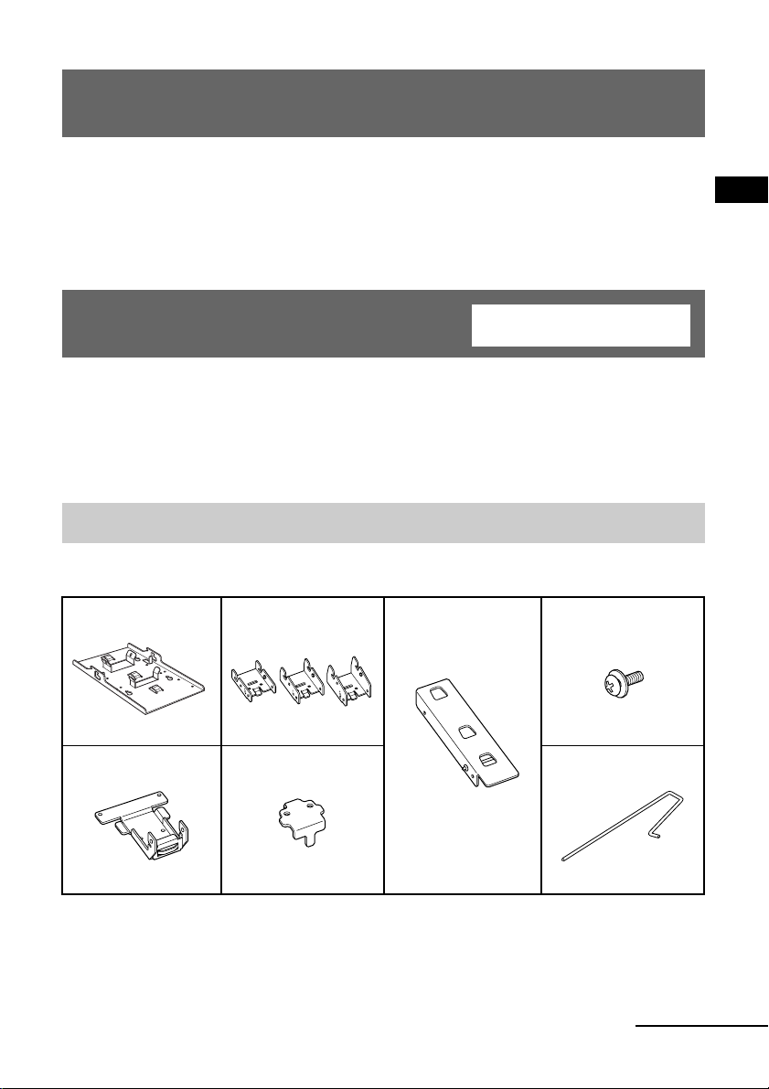
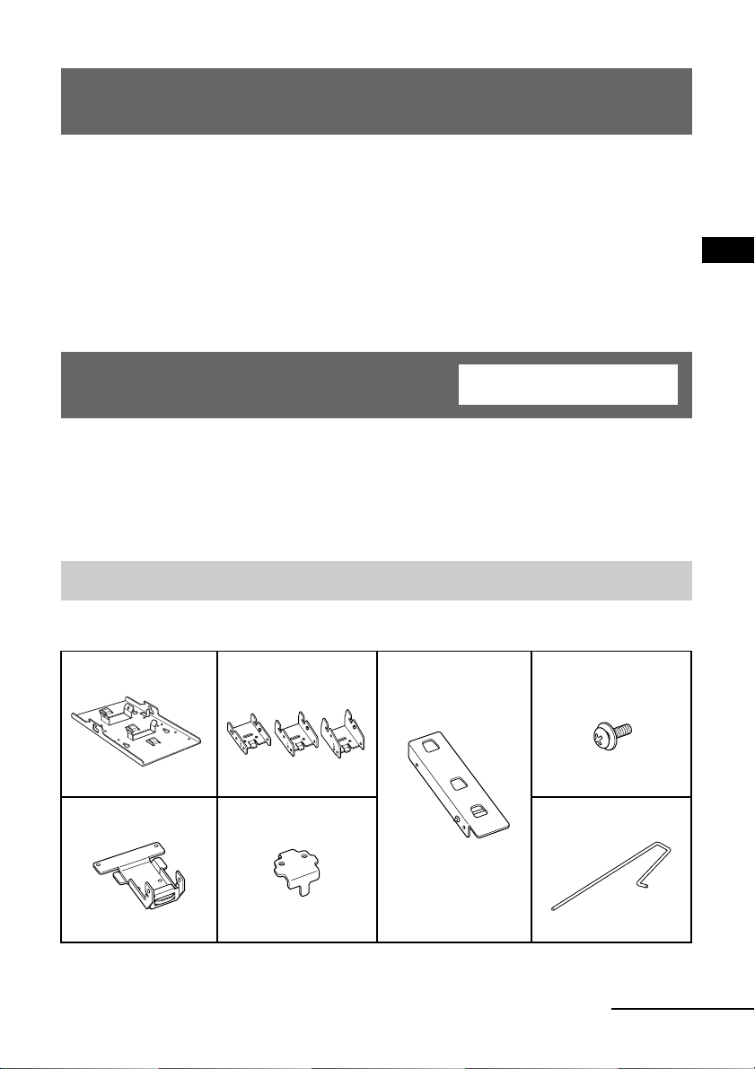
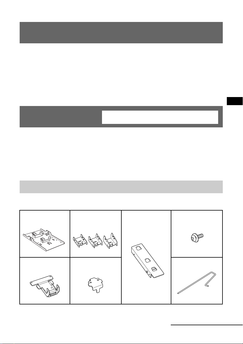
Step 1: Check the parts
Check all the parts are included in the package.
Bracket A (1) Bracket C (3)
(0°, 5°, 10°)
Bracket B (1) Bracket D (1) Locking rod (1)
Bracket E (1) Screw (6)
(with washer)
continued
3
Page 4
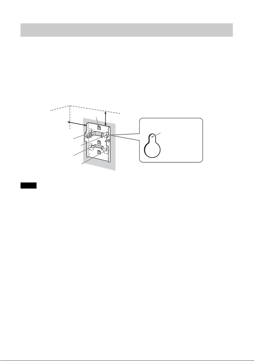
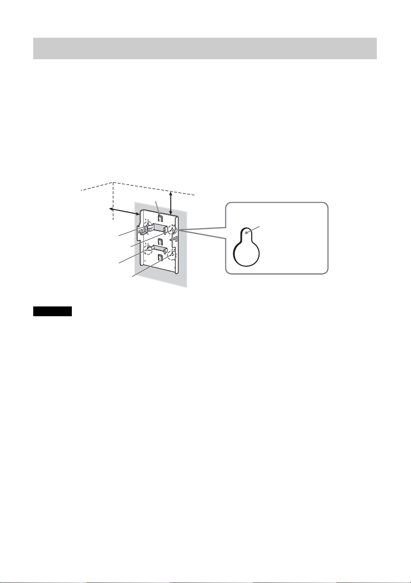
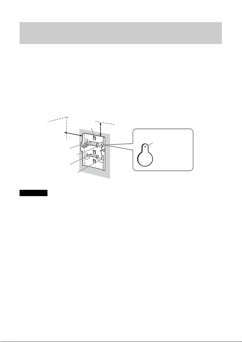
Step 2: Decide the installation location
Decide the location on the wall to install the TV.
Then, place bracket A on the installation location and mark the four screw
holes on the wall using a pencil.
Before marking the location of the holes, make sure that the distance between
the upper edge of bracket A and the ceiling is 15 cm or more, and that between
the side edge of bracket A and the side wall is 25 cm or more.
Ceiling
Bracket A
25 cm or more
Note
Attach bracket A level with the floor.
15 cm or more
Mark this
portion using
a pencil.
Wall
4
Page 5
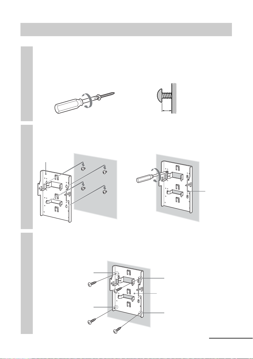
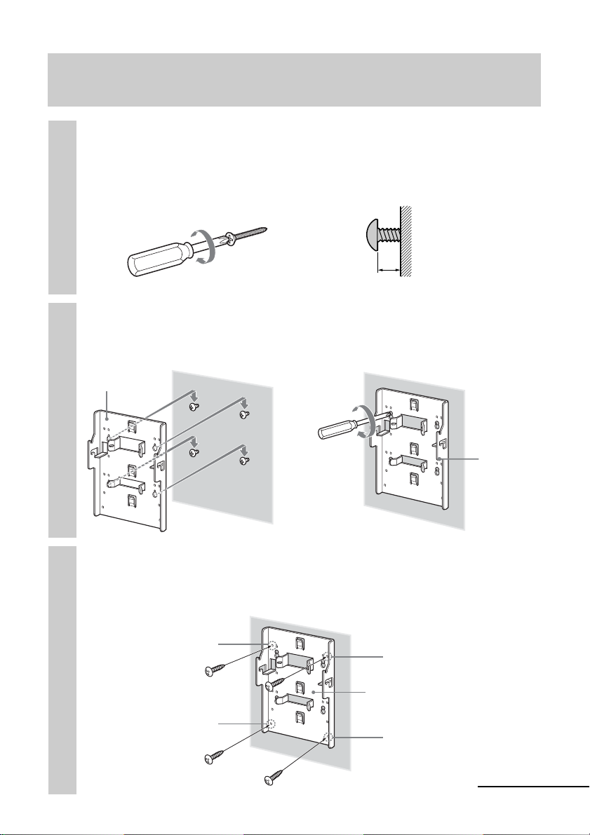
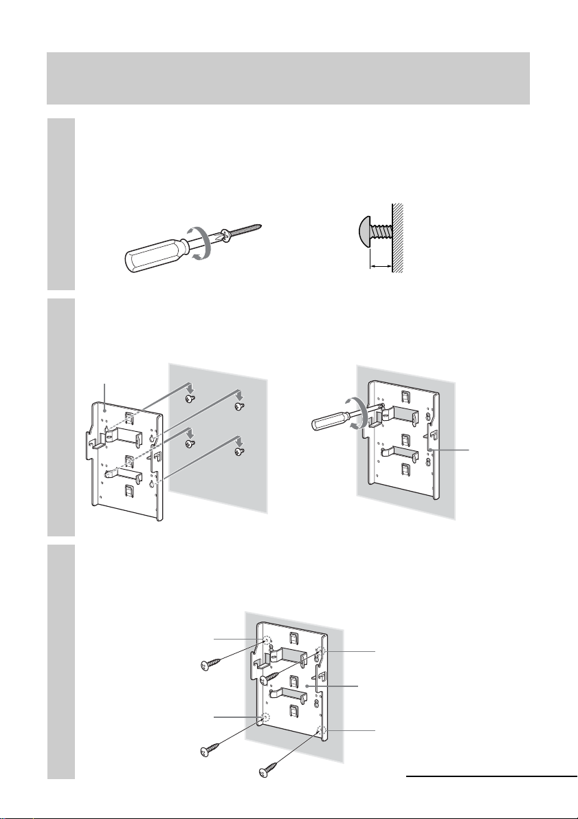
Step 3: Secure bracket A to the wall
Insert four of the screws you prepared at the positions
marked in Step 2 (page 4).
1
Do not tighten the screws completely for the moment. Keep a space of
2 to 3 mm from the wall.
Wall
Screws you
prepared
Press bracket A to the wall and slide it down. Then fully
tighten the four screws on the wall.
2
Bracket A
2 - 3 mm
,
Wall
Wall
Insert four of the screws you prepared in the screw holes,
and tighten them securely in the order of 1 to 4 as
3
shown below.
1
Screws you
prepared
4
3
Bracket A
2
Bracket A
continued
5
Page 6
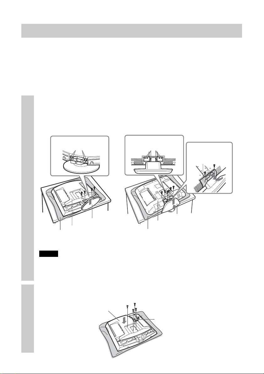
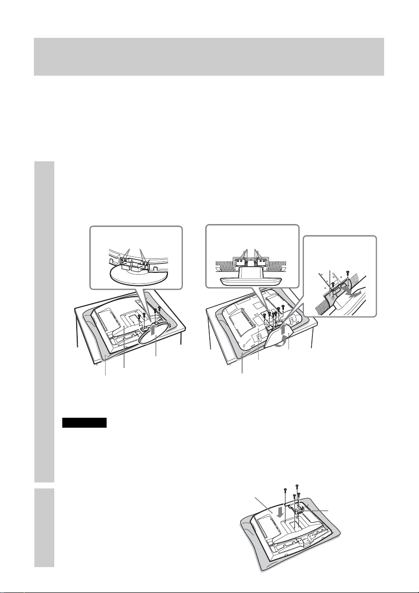
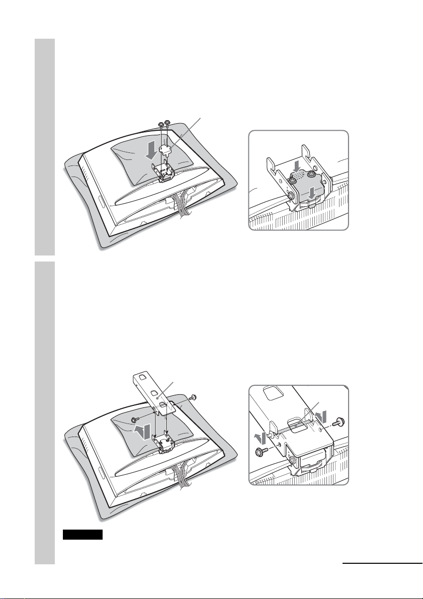
Step 4: Attach bracket B to the TV
Before attaching bracket B, remove the rear cover of the TV and disconnect all
the cables from the TV.
For how to remove the rear cover of the TV, refer to the Operating Instructions
supplied with the TV.
(The illustrations used in this manual show the KLV-21SR2/KLV-L23M1 as
examples.)
Remove the screws as shown below, and remove the TV
stand from the TV.
1
To prevent damaging the surface of the LCD display, place the TV on a
soft mat.
KLV-21SR2 KLV-L23M1
Remove the four
screws.
Remove the six screws.
(M4 type for bracket
B)
Remove the two
screws and hinge
cover.
TV stand
Soft mat
Notes
• Place the TV body only on the table as shown above. If the TV stand is also on the
table, the TV body may be unstable and cause damage.
• When removing the TV stand, hold it firmly.
Rear of the TV
Soft mat
Rear of the TV
TV stand
To secure bracket B to the TV,
use the screws removed from the
TV stand, not the ones from the
hinge cover.
Secure bracket B to the TV firmly using the four screws
removed in step 1.
2
Rear of the TV
Bracket B
6
Page 7
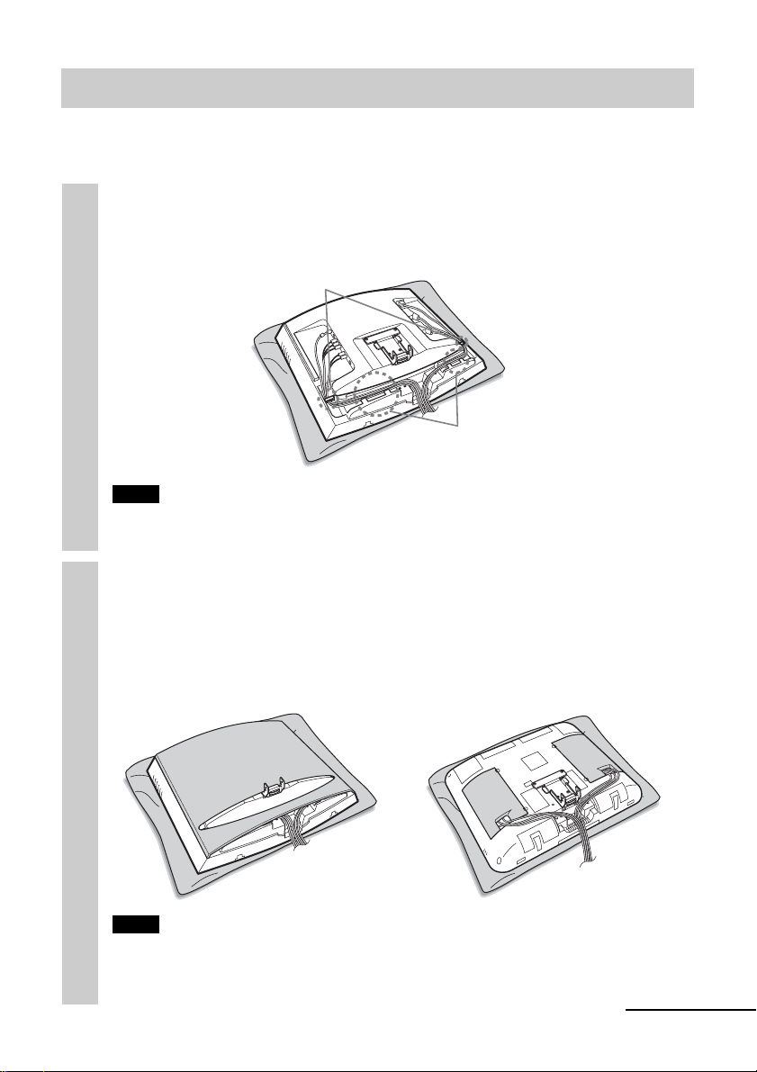
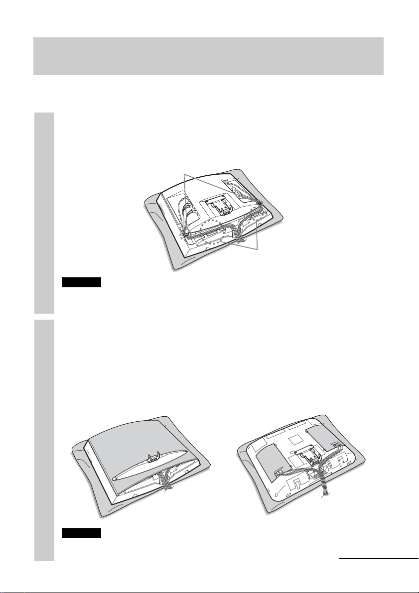
Step 5: Attach the rear cover on the TV
(The illustrations used in this manual show the KLV-21SR2/KLV-L23M1 as
examples.)
Connect the cables.
How to connect/bundle the cables differs depending on the TV model.
1
For details, refer to the Operating instruction for your TV.
Clips
Tabs
Note
If the cables are not neatly stored in the grooves, you may not be able to attach the
rear cover.
Attach the rear cover.
For KLV-L23M1, attach the cable covers instead of the rear cover. For
2
KLV-20SR3, go to Step 6 instead of attaching the rear cover.
For details on how to attach the rear cover, refer to the Operating
Instructions of the TV.
KLV-21SR2
KLV-L23M1
Note
When you attach the rear cover, make sure that bracket B does not damage the rear
cover.
continued
7
Page 8
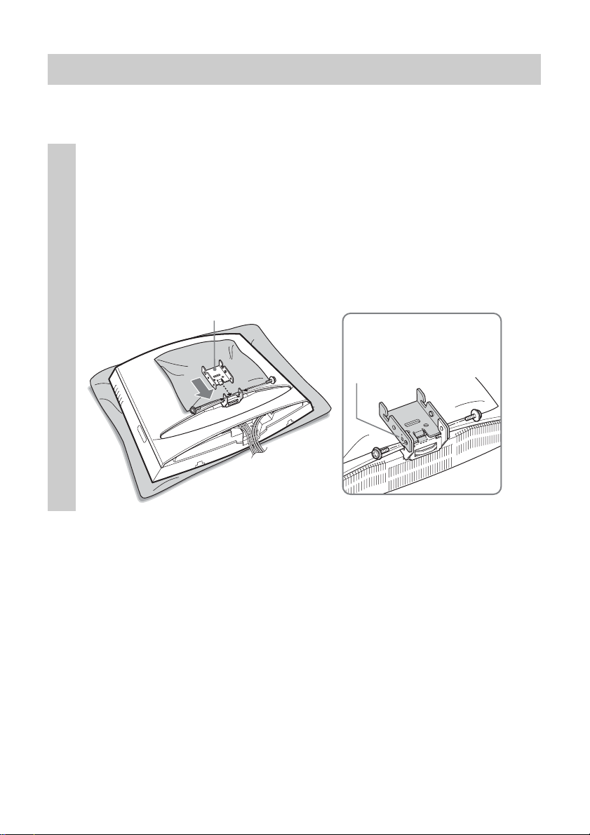
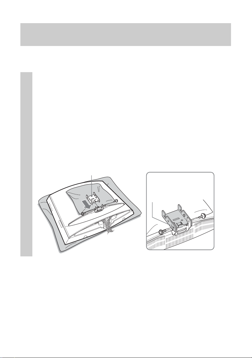
Step 6: Attach brackets C, D, and E to the TV
To prevent damaging the surface of the rear cover of the TV, put a soft mat on
the rear cover.
Attach bracket C of the desired angle to bracket B.
Insert the hooked part of bracket C into bracket B as illustrated below.
1
Confirm that both sides of bracket C are outside bracket B, and secure
them firmly with two of the supplied screws.
There are three types of bracket C, each with a different angle: 0°, 5°,
and 10°. Choose the bracket C with the desired angle to attach.
The illustration below shows an example of how to attach bracket C
with an angle of 0°.
Bracket C
The angle “0°,” “5°,” or
“10°” is marked on the
side of bracket C.
8
Page 9
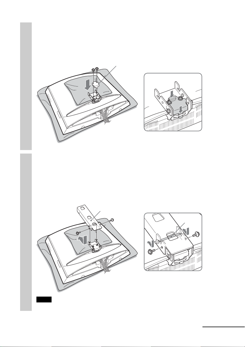
Attach bracket D to bracket C, and secure them firmly
with two of the supplied screws.
2
Place bracket D onto bracket C as illustrated below, and secure them
with the two screws.
Bracket D
Attach bracket E to bracket C, and secure them firmly
with two of the supplied screws.
3
Slide the shaft of bracket E into the notches of bracket C as illustrated
below, and secure them with the two screws one on each side. When you
complete attaching bracket E, remove the soft mat from the rear cover
of the TV.
Bracket E
Shaft
Note
Be careful not to get your fingers caught between the brackets when attaching them.
continued
9
Page 10
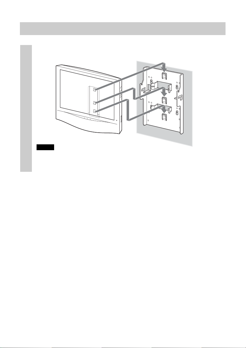
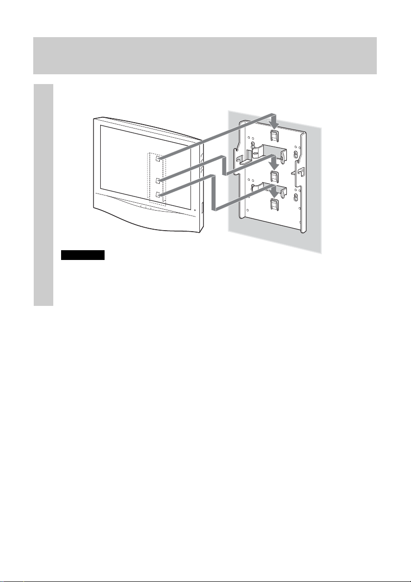
Step 7: Secure the TV to the wall
Hook bracket E on bracket A.
1
Bracket A
Bracket E
Wall
Notes
• Hold the TV firmly. Be especially careful when you secure the TV in a high place.
• Do not release the TV until you confirm that bracket E is firmly secured to bracket
A at three locations.
10
Page 11
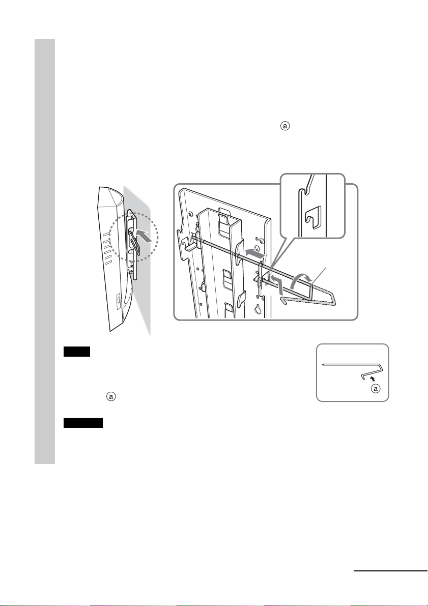
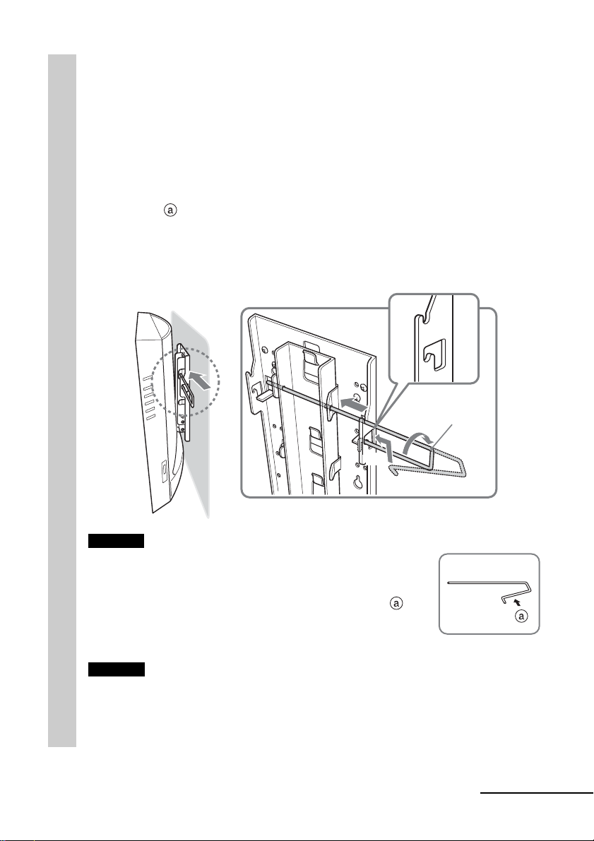
Insert the locking rod.
The locking rod can be inserted from either side. The illustration below
2
shows an example of how to insert the locking rod from the right side.
1 Insert the longer side of the locking rod into the holes on bracket
E.
2 Insert the curved side of the locking rod into the hole on bracket
A. Hold and press the locking rod at part to pass its end
through the hole.
3 Turn the locking rod until it stops to secure it in place.
1
Locking
rod
3
2
Note
To prevent the locking rod from falling out of the brackets, the
space between both ends of the locking rod is greater than that
between the holes on the brackets. Hold and press the locking
rod at part
Caution
If the TV is lifted up when the locking rod is not installed properly, the TV may fall
off the Wall-Mount Bracket and cause serious injury.
Be sure to insert and secure the locking rod in place.
so that it can pass through the holes.
continued
11
Page 12
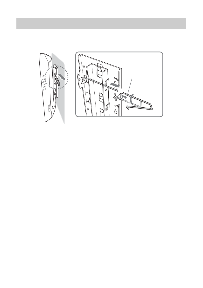
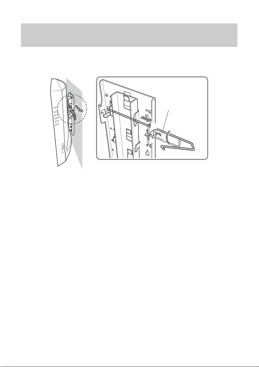
Detaching the TV from the Wall-Mount Bracket
Remove the locking rod from brackets A and E, then detach the TV from the
Wall-Mount Bracket.
3
2
Locking rod
1
12
Page 13
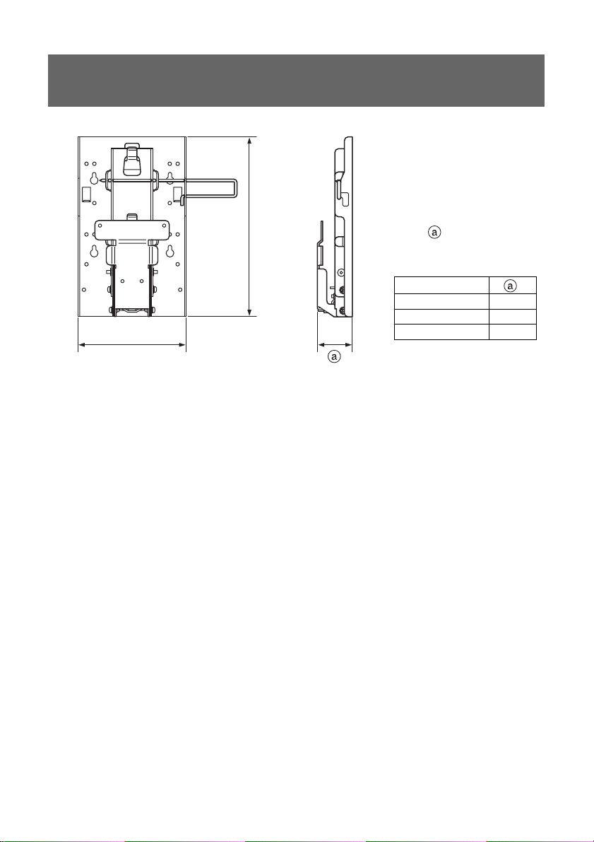
Specifications
280 mm
168 mm
Value varies
depending on the angle
of bracket C.
Bracket C angle
Bracket mass: Approx. 1.6 kg
Supportable weight: Approx. 12 kg
Design and specifications are subject to change without notice.
0° 55 mm
5° 63 mm
10° 71 mm
13
Page 14
Danke, dass Sie sich für dieses Produkt entschieden haben.
Für Kunden
Zur Installation dieses Produkts sind entsprechende Kenntnisse
erforderlich, insbesondere, um die Tragkraft der Wand sicherzustellen.
Überlassen Sie die Montage dieses Produkts an der Wand (Schritt 1 bis 3
unter „Montage“) unbedingt Sony-Händlern oder Fachleuten und ergreifen
Sie bei der Montage geeignete Sicherheitsmaßnahmen. Der Hersteller
übernimmt keine Haftung für Verletzungen bzw. Sachschäden, die durch
unsachgemäßen Umgang mit dem Produkt oder eine fehlerhafte Montage
verursacht werden. Ihre gesetzlich vorgeschriebenen Rechte (sofern
vorhanden) bleiben davon unberührt.
ACHTUNG
Bitte beachten Sie folgende Sicherheitsmaßnahmen. Andernfalls kann das
Fernsehgerät herunterfallen. Dabei besteht die Gefahr von schweren
Verletzungen und von Beschädigungen am Gerät.
•Hängen Sie sich nach der Montage nicht an die Wandhalterung oder an das
Fernsehgerät in der Wandhalterung.
• Achten Sie besonders darauf, dass das Netzkabel des Fernsehgeräts nicht
eingeklemmt wird, wenn Sie das Fernsehgerät an der Wandhalterung
anbringen.
• Gehen Sie bei der Montage nach den Anweisungen und Erläuterungen in
dieser Bedienungsanleitung vor.
Aus Sicherheitsgründen sollten Sie sich vor der Montage durch einen SonyHändler oder qualifiziertes Fachpersonal beraten lassen.
• Vergewissern Sie sich vor der Montage, dass die Tragkraft der Wand für die
Wandhalterung und das Fernsehgerät ausreicht. Für die Montage eignet sich
eine ebene, senkrechte Wand mit einer Verstärkung darin.
• Belasten Sie die Wandhalterung nach der Montage nur mit dem Fernsehgerät
und nicht mit weiteren Gewichten.
• Versuchen Sie nicht, die Komponenten der Wandhalterung zu zerlegen, zu
modifizieren oder auszutauschen.
Für Sony-Händler
Zur Installation dieses Produkts sind entsprechende Kenntnisse erforderlich.
Lesen Sie diese Gebrauchsanweisung unbedingt sorgfältig durch, damit eine
sichere Ausführung der Arbeiten gewährleistet ist. Der Hersteller übernimmt
keine Haftung für Verletzungen bzw. Sachschäden, die durch unsachgemäßen
Umgang mit dem Produkt oder eine fehlerhafte Montage verursacht werden.
Händigen Sie diese Gebrauchsanweisung nach der Installation dem Kunden aus.
2
Page 15
Vorsicht
• Diese Wandhalterung darf ausschließlich für die angegebenen LCDFarbfernsehgeräte von Sony verwendet werden.
Verwenden Sie diese Wandhalterung nicht für Fernsehgeräte, in deren
Bedienungsanleitung nicht ausdrücklich angegeben ist, dass sie mit dieser
Wandhalterung an der Wand montiert werden können.
• Achten Sie besonders bei einer Montage weit oben an der Wand darauf, dass
das Fernsehgerät nicht herunterfallen kann.
DE
Montage
Halten Sie für die Montage acht für die Wand geeignete, handelsübliche
Montageschrauben, Ankerschrauben usw. bereit.
Art und Länge der benötigten Schrauben hängen vom Material und der Stärke
der Wand ab. Wenn Sie nicht wissen, aus welchem Material die Wand besteht,
wenden Sie sich bitte an einen Sony-Händler oder qualifiziertes Fachpersonal.
Für Sony-Händler
Schritt 1: Überprüfen Sie die gelieferten Teile
Überprüfen Sie, ob alle Teile mitgeliefert wurden:
Halterung A (1) Halterung C (3)
(0°, 5°, 10°)
Halterung B (1) Halterung D (1) Sicherungsstange (1)
Halterung E (1) Schrauben (6)
(mit Unterlegscheibe)
Fortsetzung
3
Page 16
Schritt 2: Legen Sie die Montageposition fest
Legen Sie fest, wo an der Wand das Fernsehgerät befestigt werden soll.
Legen Sie dann Halterung A über die Montagestelle und markieren Sie mit
einem Bleistift die vier Montagebohrungen.
Achten Sie vor dem Markieren der Bohrungen darauf, dass der Abstand
zwischen der Oberkante von Halterung A und der Decke mindestens 15 cm
und zwischen der Seitenkante von Halterung A und einer angrenzenden
Wand mindestens 25 cm beträgt.
Decke
Halterung A
mindestens 25 cm
Hinweis
Bringen Sie Halterung A waagrecht an.
mindestens
15 cm
Wand
Markieren Sie
diesen Bereich
mit einem
Bleistift.
4
Page 17
Schritt 3: Bringen Sie Halterung A an der
Wand an
Drehen Sie vier Schrauben an den Stellen in die Wand, die
Sie in Schritt 2 (Seite 4) markiert haben.
1
Ziehen Sie die Schrauben dabei noch nicht ganz an. Lassen Sie einen
Abstand von 2 bis 3 mm zwischen Schraubenkopf und Wand.
Wand
Bereitgehaltene
Schrauben
Drücken Sie Halterung A gegen die Wand und lassen Sie
sie nach unten gleiten, so dass sie an den vier Schrauben
2
hängt. Ziehen Sie dann die vier Schauben vollständig fest.
Halterung A
2 - 3 mm
,
Wand
Setzen Sie dann die vier weiteren bereitgehaltenen
Schrauben in den Bohrungen an und ziehen Sie sie wie
3
unten abgebildet in der Reihenfolge von 1 bis 4 fest.
1
Bereitgehaltene
Schrauben
4
3
Halterung A
2
Halterung
A
Wand
Fortsetzung
5
Page 18
Schritt 4: Befestigen Sie Halterung B am
Ferhsehgerät
Bevor Sie Halterung B anbringen, nehmen Sie die hintere Abdeckung des
Fernsehgeräts ab und lösen Sie alle Kabel vom Fernsehgerät.
Schlagen Sie in der Bedienungsanleitung zum Fernsehgerät nach, wie die
hintere Abdeckung abgenommen wird.
(Die Abbildungen in dieser Gebrauchsanweisung zeigen als Beispiel das
Modell KLV-21SR2/KLV-L23M1.)
Entfernen Sie die Schrauben wie unten abgebildet und
nehmen Sie den Fernsehständer vom Fernsehgerät ab.
1
Legen Sie das Fernsehgerät dabei auf einen weichen Untergrund, zum
Beispiel ein Tuch, damit das LCD-Display nicht beschädigt wird.
KLV-21SR2
Entfernen Sie die vier
Schrauben.
Entfernen Sie die
sechs Schrauben (Typ
M4 für Halterung B).
KLV-L23M1
Entfernen Sie die
beiden Schrauben
und die
Scharnierabdeckung.
Ständer
Rückseite des
Tuch
Fernsehgeräts
Hinweise
• Legen Sie das Fernsehgerät unbedingt wie oben dargestellt auf den Tisch, so dass
der Ständer über den Tisch hinausragt. Wenn sich der Fernsehständer auch auf
dem Tisch befindet, liegt das Fernsehgerät nicht stabil und es kann zu Schäden
kommen.
• Halten Sie den Ständer gut fest, wenn Sie ihn vom Fernsehgerät abmontieren.
Schrauben Sie
Halterung B mit den
2
Um Halterung B sicher am Fernsehgerät zu
befestigen, verwenden Sie die vom
Fernsehständer entfernten Schrauben und nicht
die von der Scharnierabdeckung.
Rückseite des
Fernsehgeräts
Rückseite des
Fernsehgeräts
Tuch
Ständer
vier in Schritt 1
entfernten
Schrauben fest an
das Fernsehgerät.
6
Halterung B
Page 19
Schritt 5: Anbringen der hinteren Abdeckung
am Fernsehgerät
(Die Abbildungen in dieser Gebrauchsanweisung zeigen als Beispiel das
Modell KLV-21SR2/KLV-L23M1.)
Schließen Sie die Kabel an.
Wie Sie die Kabel anschließen bzw. bündeln, hängt vom Modell des
1
Fernsehgeräts ab. Weitere Informationen dazu finden Sie in der
Bedienungsanleitung zum Fernsehgerät.
Klemmen
Laschen
Hinweis
Wenn die Kabel nicht ordentlich in den Vertiefungen liegen, lässt sich die hintere
Abdeckung unter Umständen nicht anbringen.
Bringen Sie die hintere Abdeckung an.
Bringen Sie die hintere Abdeckung an.
2
Beim KLV-L23M1 bringen Sie statt der hinteren Abdeckung die
Kabelabdeckungen an. Beim KLV-20SR3 fahren Sie mit Schritt 6 fort,
anstatt die hintere Abdeckung anzubringen.
Erläuterungen zum Anbringen der hinteren Abdeckung finden Sie in der
Bedienungsanleitung zum Fernsehgerät.
KLV-21SR2
KLV-L23M1
Hinweis
Achten Sie beim Anbringen der hinteren Abdeckung darauf, dass diese nicht durch
die Halterung B beschädigt wird.
Fortsetzung
7
Page 20
Schritt 6: Bringen Sie Halterung C, D und E
am Fernsehgerät an
Legen Sie ein weiches Tuch auf die hintere Abdeckung des Fernsehgeräts,
damit die Oberfläche der hinteren Abdeckung nicht beschädigt wird.
Bringen Sie die Halterung C mit dem gewünschten Winkel
an Halterung B an.
1
Führen Sie den hakenförmigen Vorsprung an Halterung C wie unten
abgebildet in Halterung B ein. Vergewissern Sie sich, dass die beiden
Außenkanten von Halterung C außen an Halterung B entlang führen,
und befestigen Sie sie sicher mit zwei der mitgelieferten Schrauben.
Es gibt drei Halterungen des Typs C, von denen jede einen anderen
Winkel aufweist: 0°, 5° und 10°. Wählen Sie die Halterung C mit dem
gewünschten Winkel aus.
Die Abbildung unten zeigt, wie Sie die Halterung C mit einem Winkel
von 0° anbringen.
Halterung C
Der Winkel, „0°“, „5°“
oder „10°“, ist seitlich
an der Halterung C
angegeben.
8
Page 21
Bringen Sie Halterung D an Halterung C an und
befestigen Sie sie sicher mit zwei der mitgelieferten
2
Schrauben.
Setzen Sie Halterung D wie unten abgebildet in Halterung C ein und
befestigen Sie sie sicher mit zwei Schrauben.
Halterung D
Bringen Sie Halterung E an Halterung C an und
befestigen Sie sie sicher mit zwei der mitgelieferten
3
Schrauben.
Schieben Sie den Schaft der Halterung E wie unten abgebildet in die
Kerben an Halterung C und befestigen Sie sie mit zwei Schrauben (an
beiden Seiten je eine Schraube). Nachdem Sie Halterung E angebracht
haben, können Sie das weiche Tuch von der hinteren Abdeckung des
Fernsehgeräts entfernen.
Halterung E
Schaft
Hinweis
Achten Sie darauf, sich beim Anbringen der Halterungen nicht die Finger
einzuklemmen.
Fortsetzung
9
Page 22
Schritt 7: Hängen Sie das Fernsehgerät an die
Wand
Haken Sie Halterung E in Halterung A ein.
1
Halterung A
Halterung
E
Wand
Hinweise
• Halten Sie das Fernsehgerät gut fest. Achten Sie besonders darauf, wenn Sie das
Fernsehgerät weit oben an der Wand montieren.
• Lassen Sie das Fernsehgerät erst los, wenn Sie sich vergewissert haben, dass
Halterung E an drei Stellen sicher an Halterung A befestigt ist.
10
Page 23
Setzen Sie die Sicherungsstange ein.
Die Sicherungsstange kann von beiden Seiten aus eingesetzt werden. Die
2
Abbildung unten zeigt, wie Sie die Sicherungsstange von der rechten
Seite aus einsetzen.
1 Führen Sie das längere Ende der Sicherungsstange durch die
Bohrungen an Halterung E.
2 Führen Sie das gebogene Ende der Sicherungsstange durch die
Bohrung an Halterung A. Drücken Sie die Sicherungsstange an
der mit gekennzeichneten Stelle zusammen, damit Sie sie
durch die Bohrung schieben können.
3 Drehen Sie die Sicherungsstange bis zum Anschlag, um sie zu
fixieren.
1
Sicherungsstange
3
2
Hinweis
Damit die Sicherungsstange nicht aus den Halterungen
herausfallen kann, ist der Abstand zwischen den beiden Enden
der Stange größer als der zwischen den Bohrungen an der
Halterung. Drücken Sie die Sicherungsstange an der mit
gekennzeichneten Stelle zusammen, damit Sie sie durch die
Bohrungen führen können.
Vorsicht
Wenn das Fernsehgerät angehoben wird und die Sicherungsstange nicht
ordnungsgemäß installiert ist, kann das Fernsehgerät von der Wandhalterung
herunterfallen und schwere Verletzungen verursachen.
Setzen Sie daher unbedingt die Sicherungsstange ein und fixieren Sie sie.
Fortsetzung
11
Page 24
Abnehmen des Fernsehgeräts von der
Wandhalterung
Nehmen Sie die Sicherungsstange aus Halterung A und E heraus und
nehmen Sie das Fernsehgerät von der Wandhalterung ab.
Sicherungsstange
3
2
1
12
Page 25

Technische Daten
280 mm
168 mm
Wert hängt vom
Winkel der Halterung C
ab.
Winkel der
Halterung C
0° 55 mm
5° 63 mm
10° 71 mm
Gewicht der Halterung: ca. 1,6 kg
Tragkraft: ca. 12 kg
Änderungen, die dem technischen Fortschritt dienen, bleiben vorbehalten.
13
Page 26
Merci d’avoir fait l’acquisition de ce produit.
A l’attention des utilisateurs
L’installation de ce produit nécessite de bonnes connaissances en matière
de montage, notamment pour s’assurer de la solidité du mur. Confiez la
fixation au mur de ce produit (étapes 1 à 3 de la section « Installation ») aux
revendeurs ou prestataires Sony et veillez particulièrement à la sécurité au
cours de l’installation. Nous déclinons toute responsabilité en cas de
blessures ou de dommages consécutifs à une mauvaise manipulation ou à
une installation incorrecte. Vos droits statutaires, le cas échéant, n’en sont
pas affectés.
AVERTISSEMENT
Pour réduire les risques de blessure grave ou d’endommagement du téléviseur
suite à sa chute, suivez les précautions suivantes.
•Ne vous tenez pas au téléviseur ou au support de fixation mural du
téléviseur lorsqu’il est fixé au mur.
• Faites attention à ne pas coincer le cordon de l’adaptateur d’alimentation
secteur du téléviseur lorsque vous fixez le téléviseur au support de fixation
mural.
• Suivez les procédures et les instructions d’installation données dans ce mode
d’emploi.
Pour une installation en toute sécurité, demandez assistance à votre
revendeur Sony ou à un technicien agréé de service après vente.
• Avant de commencer l’installation, vérifiez que le mur est suffisamment
résistant pour supporter le téléviseur et le support de fixation mural.
L’emplacement choisi pour l’installation doit être un mur plat, parfaitement
droit et contenant un matériau de renforcement.
•Ne faites pas supporter un poids supérieur à celui du téléviseur au support
de fixation mural une fois qu’il est en place sur le mur.
•Ne démontez pas, ne modifiez pas et ne remplacez pas les pièces du support
de fixation mural pour téléviseur.
A l’attention des revendeurs Sony
L’installation de ce produit nécessite de bonnes connaissances en matière de
montage. Lisez entièrement le mode d’emploi afin d’effectuer une installation
en toute sécurité. Nous déclinons toute responsabilité en cas de blessures ou de
dommages consécutifs à une mauvaise manipulation ou à une installation
incorrecte. Une fois l’installation terminée, remettez le mode d’emploi aux
utilisateurs.
2
Page 27
Attention
• Ce support de fixation mural n’est destiné à être utilisé qu’avec des
téléviseurs couleur LCD de Sony.
N’utilisez pas ce support de fixation mural avec un téléviseur dont le mode
d’emploi ne cite pas l’utilisation de ce support de fixation mural.
• Faites particulièrement attention à ne pas faire tomber le téléviseur lorsque
vous l’installez à une hauteur importante sur le mur.
FR
Installation
A l’attention des revendeurs Sony
Pour l’installation, vous devez disposer de huit vis de montage, boulons
d’ancrage ou autres, disponibles dans le commerce, et adaptés au mur.
Le type et la longueur des vis nécessaires dépendent du matériau et de la
résistance du mur. Si vous ne savez pas de quel matériau votre mur est
constitué, consultez votre revendeur Sony ou un technicien agréé de service
après-vente.
1ère étape : Vérification des pièces
Vérifiez toutes les pièces incluses dans l’emballage.
Support de
fixation A (1)
Support de
fixation B (1)
Support de
fixation C (3)
(0°, 5°, 10°)
Support de
fixation D (1)
Support de
fixation E (1)
Vis (6)
(avec rondelle)
Tige de blocage (1)
suite à la page suivante
3
Page 28
2ème étape : Choix de l’emplacement
d’installation
Choisissez l’emplacement sur le mur où vous allez installer le téléviseur.
Puis, placez le support de fixation A sur l’emplacement d’installation et
marquez l’emplacement des quatre orifices des vis sur le mur avec un crayon.
Avant de marquer l’emplacement des trous, assurez-vous que la distance entre
le bord supérieur du support de fixation A et le plafond est d’au moins 15 cm,
et que celle entre le bord latéral du support de fixation A et le mur latéral est
d’au moins 25 cm.
Plafond
Support de
fixation A
Au moins 25 cm
Remarque
Fixez le support de fixation A de façon à ce qu’il soit parallèle au sol.
Au moins 15 cm
Marquez cette
portion à l’aide
d’un crayon.
Mur
4
Page 29
3éme étape : Fixation du support de fixation
A au mur
Insérez quatre des vis que vous avez préparées dans les
positions marquées à l’étape 2 (page 4).
1
Ne serrez pas les vis à fond pour le moment. Gardez un espace de
2 ou 3 mm par rapport au mur.
Mur
Vis que vous
avez préparées
Appuyez le support de fixation A contre le mur et faites-le
glisser vers le bas. Puis serrez à fond les quatre vis sur le mur.
2
Support de
fixation A
,
2 à 3 mm
Support de
fixation A
Mur
Mur
Insérez quatre des vis que vous avez préparées dans les
trous prévus à cet effet, puis vissez-les à fond dans l’ordre
3
de 1 à 4 comme indiqué ci-dessous.
1
Vis que vous
avez préparées
4
3
Support de fixation A
2
suite à la page suivante
5
Page 30

4ème étape : Fixation du support de fixation
B au téléviseur
Avant de fixer le support de fixation B, retirez l’arrière du téléviseur et
débranchez tous les câbles du téléviseur.
Pour plus de détails sur la façon de retirer le panneau arrière du téléviseur,
reportez-vous au mode d’emploi fourni avec le téléviseur.
(Les illustrations de ce manuel représentent les modèles KLV-21SR2/KLVL23M1 à titre d’exemple.)
Retirez les vis ainsi qu’il est indiqué dans l’illustration et
détachez le support du téléviseur.
1
Afin de ne pas endommager la surface de l’écran LCD, placez le
téléviseur sur un tissu doux.
KLV-21SR2 KLV-L23M1
Retirez les quatre vis.
Retirez les six vis. (de
type M4 pour le
support B)
Retirez les deux
vis et le panneau
recouvrant les
charnières.
Support du téléviseur
Tissu doux
Remarques
• Placez uniquement le corps du téléviseur sur la table comme illustré ci-dessus. Si le
support du téléviseur se trouve également sur la table, le corps du téléviseur risque
d’être instable et pourrait provoquer des dommages.
• Lorsque vous retirez le support du téléviseur, tenez-le fermement.
Arrière du
téléviseur
Fixez fermement le
support de fixation B
2
Tissu doux
Afin de fixer correctement le support B au
téléviseur, utilisez les vis que vous avez
retirées du support du téléviseur et non celles
du panneau recouvrant les charnières.
Arrière du téléviseur
Arrière du
téléviseur
Support du téléviseur
au téléviseur à l’aide
des quatre vis retirées
à l’étape 1.
6
Support de
fixation B
Page 31

5ème étape : Fixation du panneau arrière sur
le téléviseur
(Les illustrations de ce manuel représentent les modèles KLV-21SR2/KLVL23M1 à titre d’exemple.)
Raccordez les câbles.
La façon de raccorder/regrouper les câbles varie selon le modèle du
1
téléviseur. Pour plus de détails, reportez-vous au Mode d’emploi de
votre téléviseur.
Remarque
Si les câbles ne sont pas correctement rangés dans les rainures, cela risque de vous
empêcher de fixer le panneau arrière du téléviseur.
Fixez le panneau arrière.
Pour le modèle KLV-L23M1, fixez la protection des câbles au lieu du
2
panneau arrière. Pour le modèle KLV-20SR3, passez à l’Etape 6 au lieu
de fixer le panneau arrière.
Pour plus de détails sur la fixation du panneau arrière, reportez-vous au
Mode d’emploi de votre téléviseur.
KLV-21SR2
Colliers
Languettes
KLV-L23M1
Remarque
Lorsque vous fixez le panneau arrière, veillez à ce que le support B ne l’endommage
pas.
suite à la page suivante
7
Page 32

6ème étape : Pose des supports de fixation
C, D et E sur le téléviseur
Afin de ne pas endommager la surface du panneau arrière du téléviseur, placez
ce dernier sur un tissu doux.
Fixez le support de fixation C au support de fixation B
selon l’angle souhaité.
1
Insérez la partie en crochet du support de fixation C dans le support de
fixation B comme illustré ci-dessous. Vérifiez que les deux côtés du
support de fixation C sont à l’extérieur du support de fixation B et
vissez-les à fond avec les deux vis fournies.
Il existe trois types de support de fixation C, chacun ayant un angle
différent : 0°, 5° et 10°. Choisissez le support de fixation C
correspondant à l’angle souhaité.
L’illustration ci-dessous montre comment fixer le support de fixation C
avec un angle de 0°.
Support de fixation C
L’angle est gravé sur le
côté du support de
fixation C (0°, 5° ou 10°).
8
Page 33

Fixez le support de fixation D au support de fixation C en
vissant à fond deux des vis fournies.
2
Placez le support de fixation D dans le support de fixation C, comme
illustré ci-dessous, et vissez à fond les deux vis.
Support de fixation D
Fixez le support de fixation E au support de fixation C en
vissant à fond deux des vis fournies.
3
Faites glisser l’axe du support de fixation E dans les encoches du
support de fixation C, comme illustré ci-dessous, et vissez à fond les
deux vis de chaque côté. Une fois le montage du support de fixation E
terminé, retirez le tissu doux du panneau arrière du téléviseur.
Support de
fixation E
Axe
Remarque
Faites attention à ne pas vous coincer les doigts dans les supports de fixation au
moment de leur fixation.
suite à la page suivante
9
Page 34

7ème étape : Fixation du téléviseur au mur
Accrochez le support de fixation E au support de fixation
A.
1
Support de
fixation A
Support de
fixation E
Mur
Remarques
• Tenez fermement le téléviseur. Faites particulièrement attention lorsque vous fixez
le téléviseur à un endroit élevé.
• Ne relâchez pas le téléviseur avant de vous être assuré que le support de fixation E
est solidement fixé au support de fixation A aux trois emplacements indiqués cidessus.
10
Page 35

Insérez la tige de blocage.
La tige de blocage peut être insérée du côté droit ou du côté gauche.
2
L’illustration ci-dessous montre la mise en place de la tige de blocage du
côté droit.
1 Insérez la partie la plus longue de la tige de blocage dans les
orifices du support de fixation E.
2 Insérez la partie recourbée de la tige de blocage dans l’orifice du
support de fixation A. Appuyez sur la partie de la tige et
maintenez-la enfoncée pour faire passer l’extrémité dans
l’orifice.
3 Faites pivoter la tige jusqu’à ce qu’elle se bloque.
1
Tige de
blocage
3
2
Remarque
Pour empêcher que la tige de blocage ne tombe des supports
de fixation, l’espace entre les deux extrémités de la tige est
supérieur à celui entre les orifices sur les supports de fixation.
Appuyez sur la partie
pour la faire passer dans les orifices.
Attention
Si vous soulevez le téléviseur et que la tige de blocage n’est pas installée
correctement, le téléviseur risque de tomber du support de fixation mural et de
blesser gravement des personnes.
N’oubliez pas d’insérer la tige de blocage et de bien la fixer.
de la tige et maintenez-la enfoncée
suite à la page suivante
11
Page 36

Retrait du téléviseur du support de fixation
mural
Retirez la tige de blocage des supports de fixation A et E, puis déposez le
téléviseur du support de fixation mural.
3
Tige de blocage
2
1
12
Page 37

Spécifications
280 mm
168 mm
La valeur dépend de
l’angle du support de
fixation C.
Angle du support
de fixation C
0° 55 mm
5° 63 mm
10° 71 mm
Poids du support de fixation : Environ 1,6 kg
Poids pouvant être supporté : Environ 12 kg
La conception et les spécifications sont sujettes à modification sans préavis.
13
Page 38

Bedankt voor uw aankoop van dit product.
Voor klanten
Voldoende ervaring is vereist voor het installeren van dit product, vooral
om te kunnen bepalen of de muur stevig genoeg is. Laat uw Sonyhandelaar of een installatietechnicus dit product aan de muur bevestigen
(stap 1 tot en met stap 3 bij "Installatie") en houd voldoende rekening met
de veiligheid tijdens de installatie. Sony is niet aansprakelijk voor enige
schade of letsel als gevolg van onjuist gebruik of een onjuiste installatie. Dit
is niet van invloed op uw eventuele wettelijke rechten.
WAARSCHUWING
Lees de volgende voorzorgsmaatregelen door om te voorkomen dat de TV valt
en ernstig letsel of beschadiging van het toestel veroorzaakt.
•Hang niet aan de TV of de wandmontagesteun als deze aan de muur zijn
bevestigd.
• Zorg dat de kabel van de netspanningsadapter van de TV niet beklemd raakt
als u de TV op de wandmontagesteun bevestigt.
• Volg de installatieprocedure en de installatie-aanwijzingen die in deze
gebruiksaanwijzing worden beschreven.
Raadpleeg uw Sony dealer of een erkende servicetechnicus voor een veilige
installatie.
• Voordat u de steun gaat installeren, moet u controleren of de muur stevig
genoeg is om de TV en de wandmontagesteun te dragen. De plaats waar u de
steun wilt installeren, moet een verstevigde muur zijn die recht en vlak is.
• Plaats geen ander gewicht dan de TV op de wandmontagesteun als deze aan
de muur is bevestigd.
•U moet de wandmontagesteun niet uit elkaar halen of aanpassen of de
onderdelen wijzigen.
Voor Sony-handelaars
Voldoende ervaring is vereist voor het installeren van dit product. Lees deze
gebruiksaanwijzing aandachtig door zodat u de installatie veilig kunt
uitvoeren. Sony is niet aansprakelijk voor enige schade of letsel als gevolg van
onjuist gebruik of een onjuiste installatie. Na de installatie geeft u deze
gebruiksaanwijzing aan de klanten.
2
Page 39

Let op
• Deze wandmontagesteun is alleen geschikt voor de aangegeven Sony LCDkleurentelevisies.
Als het gebruik van deze steun niet wordt aangegeven in de
gebruiksaanwijzing van de TV, moet u een dergelijke TV niet gebruiken met
de steun.
•Wees voorzichtig dat u de TV niet laat vallen wanneer u deze aan de muur
bevestigt.
Installatie
Voor de installatie hebt u acht montageschroeven of verankeringsbouten nodig
die geschikt zijn voor de muur.
De soort en lengte van de benodigde schroeven is afhankelijk van het materiaal
en de draagkracht van de muur. Als u niet weet van welk materiaal de muur is
gemaakt, moet u uw Sony dealer of een erkende servicetechnicus raadplegen.
Voor Sony-handelaars
Stap 1: De onderdelen controleren
Controleer of alle onderdelen aanwezig zijn in de verpakking.
Steun A (1) Steun C (3)
(0°, 5°, 10°)
Steun B (1) Steun D (1) Vergrendelingsstang
Steun E (1) Schroef (6)
(met sluitring)
(1)
NL
wordt vervolgd
3
Page 40

Stap 2: De plaats voor installatie bepalen
Bepaal de plaats aan de muur waar u de TV wilt installeren.
Plaats steun A op de gewenste plaats en markeer de vier schroefgaten op de
muur met een potlood.
Voordat u de locatie van de gaten markeert, moet u controleren of de afstand
tussen de bovenrand van steun A en het plafond ten minste 15 cm is en de
afstand tussen de zijkant van steun A en de zijmuur ten minste 25 cm.
Plafond
Steun A
25 cm of meer
Opmerking
Bevestig steun A waterpas ten opzichte van de vloer.
15 cm of meer
Muur
Markeer dit
gedeelte met
een potlood.
4
Page 41

Stap 3: Steun A aan de muur bevestigen
Plaats vier van de schroeven die u hebt aangeschaft, op de
plaatsen die u hebt gemarkeerd in stap 2 (pagina 4).
1
Draai de schroeven nog niet volledig vast. Houd een ruimte van
2 tot 3 mm tot de muur over.
Muur
Schroeven die u
hebt aangeschaft
Duw steun A tegen de muur en schuif deze omlaag. Draai
de vier schroeven volledig vast.
2
Steun A
2 - 3 mm
,
Muur
Plaats vier van de schroeven in de schroefgaten en draai
deze in de onderstaande volgorde van 1 tot en met 4
3
vast.
1
Schroeven die u
hebt aangeschaft
4
3
Steun A
2
Steun A
Muur
wordt vervolgd
5
Page 42

Stap 4: Steun B op de TV bevestigen
Voordat u steun B bevestigt, verwijdert u de achterklep van de TV en koppelt
u alle kabels los van de TV.
Raadpleeg de gebruiksaanwijzing die bij de TV is geleverd voor meer
informatie over het verwijderen van de achterklep van de TV.
(In de afbeeldingen van deze handleiding worden de KLV-21SR2/KLV-L23M1
als voorbeeld gebruikt.)
Verwijder de schroeven zoals hieronder wordt
weergegeven en verwijder de televisiestandaard van de
1
televisie.
Plaats de TV op een zachte mat om beschadiging van het LCD-scherm te
voorkomen.
KLV-21SR2 KLV-L23M1
Verwijder de vier
schroeven.
Verwijder de zes
schroeven (type M4
voor steun B).
Verwijder de twee
schroeven en het
klepje voor het
scharnier.
TV-standaard
Zachte mat
Opmerkingen
• Plaats het televisiescherm alleen op de tafel zoals hieronder wordt aangegeven. Als
de televisiestandaard ook op de tafel staat, wordt het televisiescherm instabiel en
kan beschadigd raken.
• Als u de TV-standaard verwijdert, moet u deze stevig vasthouden.
Achterkant van de TV
Als u steun B wilt bevestigen op de televisie,
gebruikt u de schroeven die u hebt verwijderd uit de
televisiestandaard en niet de schroeven voor het
klepje van het scharnier.
Monteer steun B stevig
op de TV met de vier
2
Zachte mat
Achterkant van
de TV
TV-standaard
Achterkant van de TV
schroeven die u in stap 1
hebt verwijderd.
6
Steun B
Page 43

Stap 5: Het achterpaneel op de televisie
bevestigen
(In de afbeeldingen van deze handleiding worden de KLV-21SR2/KLV-L23M1
als voorbeeld gebruikt.)
Sluit de kabels aan.
Het aansluiten en bundelen van kabels verschilt per televisiemodel.
1
Raadpleeg de gebruiksaanwijzing van de televisie voor meer informatie.
Klemmetjes
Nokjes
Opmerking
Als de kabels niet goed in de groeven vallen, kunt u de achterklep wellicht niet
bevestigen.
Bevestig het achterpaneel.
Voor de KLV-L23M1 bevestigt u de kabeldeksels in plaats van het
2
achterpaneel. Voor de KLV-20SR3 gaat u naar stap 6 in plaats van het
achterpaneel te bevestigen.
Raadpleeg de gebruiksaanwijzing van de televisie voor meer informatie
over het bevestigen van het achterpaneel.
KLV-21SR2 KLV-L23M1
Opmerking
Als u het achterpaneel bevestigt, moet u ervoor zorgen dat het achterpaneel niet
wordt beschadigd door steun B.
wordt vervolgd
7
Page 44

Stap 6: Steun C, D en E op de TV bevestigen
Plaats een zachte mat op de achterklep om te voorkomen dat het oppervlak
van de achterklep wordt beschadigd.
Bevestig de steun C met de gewenste hoek op steun B.
Plaats de haak van steun C in steun B, zoals hieronder wordt
1
weergegeven. Controleer of beide zijden van steun C zich buiten steun
B bevinden en zet deze vast met twee van de bijgeleverde schroeven.
Er zijn drie soorten voor steun C, elk met een andere hoek: 0°, 5° en 10°.
Kies de steun C met de gewenste hoek om deze te bevestigen.
In de onderstaande afbeelding wordt weergegeven hoe u de steun C
met een hoek van 0° kunt bevestigen.
Steun C
De hoek "0°", "5°" of
"10°" is aangegeven op
de zijkant van steun C.
8
Page 45

Bevestig steun D op steun C en zet deze stevig vast met
twee van de bijgeleverde schroeven.
2
Plaats steun D in steun C, zoals hieronder wordt weergegeven, en zet
deze vast met de twee schroeven.
Steun D
Bevestig steun E op steun C en zet deze stevig vast met
twee van de bijgeleverde schroeven.
3
Schuif de schacht van steun E in de inkepingen van steun C, zoals
hieronder wordt weergegeven, en zet deze aan beide zijden met twee
schroeven vast. Als u steun E hebt bevestigd, verwijdert u de zachte
mat van de achterklep van de TV.
Steun E
Schacht
Opmerking
Wees voorzichtig en zorg dat uw vingers niet beklemd raken tussen de steunen
wanneer u deze bevestigt.
wordt vervolgd
9
Page 46

Stap 7: De TV aan de muur bevestigen
Bevestig steun E op steun A.
1
Steun A
Steun E
Muur
Opmerkingen
• Houd de TV stevig vast. Wees voorzichtig als u de TV op een hoge plaats bevestigt.
• Laat de TV pas los als u hebt gecontroleerd of steun E op drie plaatsen stevig is
bevestigd op steun A.
10
Page 47

Plaats de vergrendelingsstang.
U kunt de vergrendelingsstang van beide zijden plaatsen. In de
2
onderstaande afbeelding wordt weergegeven hoe u de
vergrendelingsstang plaatst vanaf de rechterzijde.
1 Plaats de lange zijde van de vergrendelingsstang in de
openingen van steun E.
2 Plaats de gebogen zijde van de vergrendelingsstang in de
opening van steun A. Houd deel van de vergrendelingsstang
ingedrukt zodat het uiteinde door de opening kan worden
gevoerd.
3 Draai de vergrendelingsstang totdat deze stevig vastzit.
1
Vergrendelings-
3
2
stang
Opmerking
De ruimte tussen beide uiteinden van de vergrendelingsstang
is groter dan die tussen de openingen van de steunen om te
voorkomen dat de vergrendelingsstang uit de steunen valt.
Houd deel
deze door de openingen kan worden gevoerd.
Let op
Als de TV wordt opgetild en de vergrendelingsstang niet goed is bevestigd, kan de
TV van de wandmontagesteun vallen en ernstig letsel veroorzaken.
Zorg dat u de vergrendelingsstang stevig vastzet.
van de vergrendelingsstang ingedrukt zodat
wordt vervolgd
11
Page 48

De TV van de wandmontagesteun halen
Verwijder de vergrendelingsstang uit steun A en E en verwijder de TV van
de wandmontagesteun.
Vergrendelings-
3
stang
2
1
12
Page 49

Technische gegevens
280 mm
168 mm
Waarde verschilt,
afhankelijk van de hoek
van steun C.
Hoek van
steun C
0° 55 mm
5° 63 mm
10° 71 mm
Gewicht van steun: Ong. 1,6 kg
Ondersteund gewicht: Ong. 12 kg
Wijzigingen in ontwerp en technische gegevens zijn voorbehouden zonder
voorafgaande kennisgeving.
13
Page 50

Gracias por adquirir este producto.
Para clientes
Se requiere suficiente experiencia para instalar este producto,
especialmente para asegurar la resistencia de la pared. Acuda a
distribuidores o contratistas de Sony para realizar la instalación de este
producto en la pared (pasos 1 a 3 del apartado “Instalación”) y preste
especial atención a la seguridad durante la instalación. Declinamos
cualquier responsabilidad por los daños o heridas producidos por una
manipulación incorrecta o una instalación inadecuada. Sus derechos legales
(en caso de haberlos) no se ven afectados.
ADVERTENCIA
Para evitar el riesgo de caídas que puedan provocar lesiones o daños graves en
el televisor, tome las siguientes precauciones.
•No se apoye en el televisor ni en el soporte de montaje mural instalado en la
pared.
• Asegúrese de no atrapar el cable del adaptador de alimentación de CA del
televisor al fijar el televisor al soporte de montaje mural.
• Siga los procedimientos e instrucciones de instalación descritos en el presente
manual.
Para garantizar la seguridad de la instalación, póngase en contacto con su
distribuidor Sony o con personal de servicio técnico cualificado.
• Antes de realizar la instalación, compruebe que la pared sea lo
suficientemente resistente como para sostener el televisor y el soporte de
montaje mural. La instalación debe realizarse en una pared plana,
perpendicular y con material de refuerzo en el interior.
•No aplique un peso que no sea el del televisor en el soporte de montaje mural
instalado en la pared.
•No desmonte, modifique ni cambie las piezas del soporte de montaje mural.
Para distribuidores Sony
Se requiere suficiente experiencia para instalar este producto. Asegúrese de
leer detenidamente este manual de instrucciones para poder realizar con
seguridad el proceso de instalación. Declinamos cualquier responsabilidad por
los daños o heridas producidos por una manipulación incorrecta o una
instalación inadecuada. Después de la instalación, entregue este manual de
instrucciones a los clientes.
2
Page 51

Precauciones
• Este soporte de montaje mural de televisor está destinado exclusivamente
para televisores en color de pantalla de cristal líquido de Sony.
No utilice el soporte con un televisor en cuyas instrucciones no se especifique
explícitamente la utilización de este soporte.
• Tenga especial cuidado para evitar la caída del televisor cuando lo instale en
alto en una pared.
Instalación
Para la instalación, prepare ocho tornillos de montaje, pernos de anclaje, etc.
disponibles en el mercado que sean adecuados para la pared.
El tipo y medida de los tornillos necesarios dependen del material y la
resistencia de la pared. Si desconoce con qué material está construida la pared,
póngase en contacto con su distribuidor Sony o con personal de servicio
técnico cualificado.
Para distribuidores Sony
Paso 1: Compruebe las piezas
Compruebe que el paquete contenga todas las piezas.
Soporte A (1)
Soporte B (1) Soporte D (1) Barra de bloqueo (1)
Soporte C (3)
(0°, 5°, 10°)
Soporte E (1)
Tornillo (6)
(con arandela)
ES
continúa
3
Page 52

Paso 2: Elija el sitio para la instalación
Decida en qué parte de la pared desea instalar el televisor.
A continuación, sitúe el soporte A donde realizará la instalación y marque en
la pared con un lápiz los cuatro orificios para los tornillos.
Antes de marcar la ubicación de los orificios, compruebe que la distancia entre
el extremo superior del soporte A y el techo es de 15 cm o más, y de que la
distancia entre el extremo lateral del soporte A y la pared contigua sea igual o
superior a 25 cm.
Techo
Soporte A
25 cm o más
Nota
Ajuste el nivel del soporte A con el suelo.
15 cm o más
Pared
Marque esta
zona con un
lápiz.
4
Page 53

Paso 3: Fije el soporte A a la pared
Introduzca cuatro de los tornillos preparados en las
posiciones marcadas en el paso 2 (página 4).
1
De momento, no apriete los tornillos completamente. Deje un espacio de
2 a 3 mm entre ellos y la pared.
Pared
Tornillos
preparados
Presione el soporte A contra la pared y deslícelo hacia
abajo. A continuación, apriete completamente los cuatro
2
tornillos en la pared.
Soporte A
2 - 3 mm
,
Pared
Introduzca cuatro de los tornillos preparados en los
orificios de los tornillos y apriételos firmemente en el
3
orden de 1 a 4 tal como se muestra a continuación.
1
Tornillos
preparados
4
3
Soporte A
2
Soporte A
Pared
continúa
5
Page 54

Paso 4: Fije el soporte B al televisor
Antes de fijar el soporte B, retire la cubierta posterior del televisor y
desconecte todos los cables del televisor.
Para obtener instrucciones sobre cómo retirar la cubierta posterior del televisor,
consulte el manual de instrucciones suministrado con el televisor.
(Las ilustraciones incluidas en este manual utilizan los modelos KLV-21SR2/
KLV-L23M1 como ejemplo.)
Extraiga los tornillos como se indica a continuación y retire
el soporte del televisor.
1
Para evitar posibles daños en la superficie de la pantalla de cristal
líquido, sitúe el televisor sobre una esterilla blanda.
KLV-21SR2
Extraiga los cuatro
tornillos.
Extraiga los seis
tornillos. (tipo M4 para
el soporte B)
KLV-L23M1
Extraiga los dos
tornillos y la
cubierta de la
bisagra.
Soporte de televisor
Esterilla blanda
Notas
• Coloque únicamente el televisor encima de la mesa como se indica arriba. Si
también coloca el soporte del televisor, el equipo puede desestabilizarse y provocar
daños o lesiones.
• Al retirar el soporte de televisor, sujételo con firmeza.
Parte posterior del televisor
Fije firmemente el
soporte B al televisor
2
Esterilla blanda
Para fijar el soporte B al televisor, utilice los
tornillos que ha extraído del soporte del televisor
y no los de la cubierta de la bisagra.
Parte posterior
del televisor
Soporte de televisor
Parte posterior del televisor
mediante los cuatro
tornillos desenroscados
en el paso 1.
6
Soporte B
Page 55

Paso 5: Coloque la cubierta posterior en el
televisor
(Las ilustraciones incluidas en este manual utilizan los modelos KLV-21SR2/
KLV-L23M1 como ejemplo.)
Conecte los cables.
La manera de conectar o agrupar los cables puede variar según el
1
modelo de televisor. Para obtener más información, consulte el manual
de instrucciones del televisor.
Pinzas
Lengüetas
Nota
Si los cables no se colocan correctamente en las ranuras, es posible que no pueda
colocar la cubierta posterior.
Coloque la cubierta posterior.
En el modelo KLV-L23M1, coloque las cubiertas de los cables en lugar de
2
la cubierta posterior. En el modelo KLV-20SR3, vaya al paso 6 en lugar
de colocar la cubierta posterior.
Para obtener más información acerca de la colocación de la cubierta
posterior, consulte el manual de instrucciones del televisor.
KLV-21SR2 KLV-L23M1
Nota
Cuando coloque la cubierta posterior, asegúrese de que el soporte B no puede
provocar ningún daño en la cubierta posterior.
continúa
7
Page 56

Paso 6: Fije los soportes C, D y E al televisor
Para evitar que la superficie de la cubierta posterior del televisor se dañe,
coloque una esterilla blanda sobre ella.
Fije el soporte C del ángulo que desee al soporte B.
Inserte la parte en forma de gancho del soporte C en el soporte B tal
1
como se ilustra a continuación. Compruebe que los dos lados del soporte
C están fuera del soporte B y fíjelos firmemente con dos de los tornillos
suministrados.
Hay tres tipos de soporte C, cada uno con un ángulo diferente: 0°, 5° y
10°. Elija el soporte C con el ángulo que desee para fijarlo.
La siguiente ilustración muestra un ejemplo de cómo fijar el soporte C
con un ángulo de 0°.
Soporte C
El ángulo “0°”, “5°” o
“10°” está marcado en
el lado del soporte C.
8
Page 57

Fije el soporte D al soporte C y sujételos firmemente con
dos de los tornillos suministrados.
2
Coloque el soporte D sobre el soporte C tal como se ilustra a
continuación y fíjelos firmemente con los dos tornillos.
Soporte D
Fije el soporte E al soporte C y sujételos firmemente con
dos de los tornillos suministrados.
3
Deslice el eje del soporte E dentro de las muescas del soporte C tal
como se ilustra a continuación y fíjelo firmemente con los dos tornillos,
uno en cada lado. Cuando termine de fijar el soporte E, retire la esterilla
blanda de la cubierta posterior del televisor.
Soporte E
Eje
Nota
Tenga cuidado de no pillarse los dedos entre los soportes cuando los fije.
continúa
9
Page 58

Paso 7: Fije el televisor a la pared
Enganche el soporte E al soporte A.
1
Soporte A
Soporte E
Pared
Notas
• Sujete firmemente el televisor. Tenga especial cuidado al fijar el televisor en un sitio
elevado.
• No suelte el televisor hasta que compruebe que el soporte E está firmemente sujeto
al soporte A en las tres ubicaciones.
10
Page 59

Introduzca la barra de bloqueo.
La barra de bloqueo puede introducirse desde ambos lados. La siguiente
2
ilustración muestra un ejemplo de cómo introducir la barra de bloqueo
desde el lado derecho.
1 Introduzca el lado más largo de la barra de bloqueo en los
orificios del soporte E.
2 Introduzca el lado curvado de la barra de bloqueo en el orificio
del soporte A. Sujete la barra de bloqueo y presiónela en la
parte para pasar el extremo a través del orificio.
3 Gire la barra de bloqueo hasta que se detenga para fijarla en su
posición.
1
Barra de
bloqueo
3
2
Nota
Para evitar que la barra de bloqueo se salga de los soportes, el
espacio entre ambos extremos de la barra es mayor que el
espacio entre los orificios de los soportes. Sujete la barra de
bloqueo y presiónela en la parte
por los orificios.
Precaución
Si se levanta el televisor cuando la barra de bloqueo no está instalada correctamente,
la unidad podría caerse del soporte de montaje mural y provocar lesiones graves.
Asegúrese de introducir y fijar la barra de bloqueo en su posición.
de forma que pueda pasar
continúa
11
Page 60

Retirar el televisor del soporte de montaje
mural
Retire la barra de bloqueo de los soportes A y E y, a continuación, separe el
televisor del soporte de montaje mural.
3
Barra de bloqueo
2
1
12
Page 61

Especificaciones
280 mm
168 mm
El valor varía según el
ángulo del soporte C.
Ángulo del
soporte C
0° 55 mm
5° 63 mm
10° 71 mm
Peso del soporte: 1,6 kg aprox.
Peso soportable: 12 kg aprox.
El diseño y las especificaciones están sujetos a cambios sin previo aviso.
13
Page 62

Complimenti per l’acquisto del presente prodotto.
Per i clienti
Per l’installazione del presente prodotto, in particolare per assicurarsi della
solidità della parete, è necessario disporre di sufficiente competenza. Per
l’installazione a parete del presente prodotto (dal punto 1 al punto 3 della
sezione “Installazione”), rivolgersi a rivenditori o installatori Sony e
prestare particolare attenzione alla sicurezza durante l’installazione. Sony
non può essere ritenuta responsabile per eventuali danni o ferite causati da
uso errato o installazione non adeguata del prodotto. Ciò non incide su
eventuali diritti legali dell’utente.
ATTENZIONE
Per evitare il rischio di ferirsi o di danneggiare il televisore a seguito di
un’eventuale caduta dell’apparecchio stesso, è necessario osservare le seguenti
precauzioni.
•Non esercitare pressione eccessiva sul televisore o sulla staffa di montaggio
installata alla parete.
• Prestare attenzione affinché il cavo dell’alimentatore CA del televisore non
rimanga incastrato quando quest’ultimo viene fissato all’apposita staffa di
montaggio a parete.
• Seguire attentamente le procedure e le istruzioni di installazione descritte nel
presente manuale.
Per installare l’apparecchio in modo sicuro, rivolgersi al proprio rivenditore
Sony o a personale di assistenza qualificato.
• Prima di procedere all’installazione, verificare che la parete sia in grado di
sostenere il televisore e la staffa di montaggio. È necessario installare
l’apparecchio su una parete piatta e perfettamente verticale dotata di
armatura interna.
•Non applicare alla staffa installata in posizione una pressione diversa dal
peso del televisore.
•Non smontare, modificare o sostituire le parti della staffa di montaggio a
parete.
Per i rivenditori Sony
Per l’installazione del presente prodotto, è necessario disporre di sufficiente
competenza. Leggere con attenzione il presente manuale di istruzioni per
garantire la sicurezza durante l’installazione. Sony non può essere ritenuta
responsabile per eventuali danni o ferite causati da uso errato o installazione
non adeguata del prodotto. Una volta terminata l’installazione, consegnare il
presente manuale di istruzioni al cliente.
2
Page 63

Avvertimento
• La presente staffa di montaggio a parete è stata progettata esclusivamente
per i televisori con display LCD a colori Sony specificati.
Non utilizzare la staffa con un televisore nelle cui istruzioni non ne è
specificato l’uso.
• Prestare particolare attenzione a non fare cadere il televisore durante
l’installazione a parete.
Installazione
Per l’installazione, è necessario disporre di otto viti di montaggio disponibili in
commercio, di bulloni di ancoraggio e così via, adatti alla parete.
Il tipo e la lunghezza delle viti necessarie dipendono dal materiale e dalla
resistenza della parete. Se non si conosce il materiale di cui è costituita la
parete, rivolgersi al proprio rivenditore Sony o a personale di assistenza
qualificato.
Per i rivenditori Sony
Punto 1: Verifica dei componenti
Verificare che nessun componente risulti mancante nella confezione.
Staffa A (1) Staffa C (3)
(0°, 5°, 10°)
Staffa B (1) Staffa D (1) Dispositivo di
Staffa E (1) Viti (6)
(con rondella)
bloccaggio (1)
IT
continua
3
Page 64

Punto 2: Individuare il luogo appropriato per
l’installazione
Individuare il punto della parete in cui si desidera installare il televisore.
Quindi, posizionare la staffa A in corrispondenza del punto di installazione e
contrassegnare i quattro fori per le viti sulla parete utilizzando una matita.
Prima di eseguire tale operazione, assicurarsi che la distanza tra l’estremità
superiore della staffa A e il soffitto sia pari o superiore a 15 cm e che quella tra
l’estremità laterale della staffa A e la parete laterale sia pari o superiore a
25 cm.
Soffitto
25 cm o
superiore
Nota
Applicare la staffa A in posizione parallela rispetto al pavimento.
Staffa A
15 cm o superiore
Contrassegnare
questa parte
utilizzando
una matita.
Parete
4
Page 65

Punto 3: Fissare la staffa A alla parete
Inserire quattro delle viti precedentemente preparate in
corrispondenza delle posizioni contrassegnate al Punto 2
1
(pagina 4).
Per il momento, non stringere completamente le viti. Lasciare uno spazio
di 2 - 3 mm dalla parete.
Parete
Viti
precedentemente
preparate
Premere la staffa A verso la parete, quindi farla scorrere
verso il basso. Infine, stringere completamente le quattro
2
viti alla parete.
Staffa A
2 - 3 mm
,
Parete
Parete
Inserire negli appositi fori quattro delle viti
precedentemente preparate, quindi stringerle saldamente
3
nell’ordine da 1 a 4 come illustrato di seguito.
1
Viti precedentemente
preparate
4
3
Staffa A
2
Staffa A
continua
5
Page 66

Punto 4: Applicare la staffa B al televisore
Prima di applicare la staffa B, rimuovere il coperchio posteriore del televisore
e scollegare tutti i cavi dal televisore stesso.
Per le modalità di rimozione del coperchio posteriore del televisore, consultare
le istruzioni per l’uso in dotazione con il televisore stesso.
(Nelle illustrazioni del presente manuale il KLV-21SR2/KLV-L23M1 è
utilizzato a scopo esemplificativo.)
Rimuovere le viti come raffigurato di seguito, quindi il
supporto dal televisore.
1
Onde evitare di danneggiare la superficie del display LCD, collocare il
televisore su un tessuto morbido.
KLV-21SR2 KLV-L23M1
Rimuovere le quattro
viti.
Rimuovere le sei viti
(tipo M4 per la staffa
B).
Rimuovere le due
viti e il
copricerniera.
Supporto del televisore
Tessuto morbido
Parte posteriore del televisore
Per fissare la staffa B al televisore, utilizzare le viti
rimosse dal supporto del televisore e non quelle
rimosse dal copricerniera.
Note
• Collocare il solo televisore sul tavolo, come raffigurato sopra. Se anche il supporto
del televisore viene posizionato sul tavolo, il televisore potrebbe risultare instabile e
causare danni.
• Per rimuovere il supporto del televisore, tenerlo saldamente.
Tessuto morbido
Supporto del televisore
Parte posteriore del televisore
Fissare la staffa B
al televisore in
2
Parte posteriore
del televisore
modo saldo
utilizzando le
quattro viti rimosse
al punto 1.
6
Staffa B
Page 67

Punto 5: Installare il coperchio posteriore sul
televisore
(Nelle illustrazioni del presente manuale il KLV-21SR2/KLV-L23M1 è
utilizzato a scopo esemplificativo.)
Collegare i cavi.
Il collegamento/raggruppamento dei cavi varia in base al modello di
1
televisore in uso. Per ulteriori informazioni, consultare le istruzioni per
l’uso del televisore.
Fascette
Linguette
Nota
Se i cavi non vengono inseriti in modo corretto nelle scanalature, potrebbe non essere
possibile applicare il coperchio posteriore.
Installare il coperchio posteriore.
Per il KLV-L23M1, installare al posto del coperchio posteriore i copricavi.
2
Per il KLV-20SR3, passare direttamente al punto 6.
Per ulteriori informazioni sull’uso del coperchio posteriore, consultare le
Istruzioni per l’uso del televisore.
KLV-21SR2
Nota
Durante l’installazione del coperchio posteriore, prestare attenzione a non
danneggiare lo stesso con la staffa B.
KLV-L23M1
continua
7
Page 68

Punto 6: Applicare le staffe C, D ed E al
televisore
Onde evitare di danneggiare la superficie del coperchio posteriore del
televisore, sistemarvi sopra un tessuto morbido.
Applicare la staffa C con l’angolo desiderato alla staffa B.
Inserire la parte dotata di gancetto della staffa C nella staffa B come
1
illustrato di seguito. Verificare che entrambi i lati della staffa C siano
all’esterno della staffa B, quindi fissarli in modo saldo utilizzando due
delle viti in dotazione.
Sono disponibili tre tipi di staffa C, ciascuno con un angolo differente:
0°, 5° e 10°. Selezionare la staffa C con l’angolo desiderato che si
desidera applicare.
L’illustrazione riportata di seguito mostra un esempio di applicazione
della staffa C con un angolo di 0°.
Staffa C
L’indicazione relativa
all’angolo “0°”, “5°” o
“10°” è riportata sul
lato della staffa C.
8
Page 69

Applicare la staffa D alla staffa C, quindi fissarle in modo
saldo utilizzando due delle viti in dotazione.
2
Posizionare la staffa D sulla staffa C come illustrato di seguito, quindi
fissarle utilizzando le due viti.
Staffa D
Applicare la staffa E alla staffa C, quindi fissarle in modo
saldo utilizzando due delle viti in dotazione.
3
Inserire l’asta della staffa E nelle tacche sulla staffa C come illustrato di
seguito, quindi fissarle utilizzando le due viti, una per ciascun lato. Una
volta completata l’applicazione della staffa E, rimuovere il tessuto
morbido dal coperchio posteriore del televisore.
Staffa E
Asta
Nota
Prestare attenzione a non far rimanere le dita incastrate tra le staffe durante
l’applicazione.
continua
9
Page 70

Punto 7: Fissare il televisore alla parete
Agganciare la staffa E alla staffa A.
1
Staffa A
Staffa E
Parete
Note
• Tenere saldamente il televisore. Prestare particolare attenzione nel caso in cui il
televisore venga fissato in posizione elevata.
• Prima di rilasciare il televisore, verificare che la staffa E sia fissata saldamente alla
staffa A in tre punti.
10
Page 71

Inserire il dispositivo di bloccaggio.
È possibile inserire il dispositivo di bloccaggio da uno dei due lati.
2
L’illustrazione riportata di seguito mostra un esempio di inserimento del
dispositivo di bloccaggio dal lato destro.
1 Inserire la parte più lunga del dispositivo di bloccaggio nei fori
sulla staffa E.
2 Inserire il lato ricurvo del dispositivo di bloccaggio nel foro sulla
staffa A. Tenere premuto il dispositivo di bloccaggio in
corrispondenza del punto per farne passare l’estremità
attraverso il foro.
3 Ruotare il dispositivo di bloccaggio fino a che non si arresta
saldamente in posizione.
1
2
Nota
Onde evitare che il dispositivo di bloccaggio fuoriesca dalle
staffe, lo spazio tra entrambe le estremità del dispositivo è
superiore rispetto a quello tra i fori sulle staffe. Tenere
premuto il dispositivo di bloccaggio in corrispondenza del
punto
Avvertimento
Se il televisore viene sollevato e il dispositivo di bloccaggio non è installato
correttamente, è possibile che il televisore si stacchi dalla staffa di montaggio a parete
causando ferite gravi.
Assicurarsi di inserire e fissare il dispositivo di bloccaggio in posizione.
in modo tale che passi attraverso i fori.
Dispositivo di
bloccaggio
3
continua
11
Page 72

Rimozione del televisore dalla staffa a parete
per TV
Rimuovere il dispositivo di bloccaggio dalle staffe A ed E, quindi staccare il
televisore dalla staffa di montaggio a parete.
Dispositivo di
3
bloccaggio
2
1
12
Page 73

Caratteristiche tecniche
280 mm
168 mm
Il valore varia in base
all’angolo della staffa C.
Angolo della
staffa C
0° 55 mm
5° 63 mm
10° 71 mm
Peso della staffa: circa 1,6 kg
Peso sostenibile: circa 12 kg
Il design e le caratteristiche tecniche sono soggetti a modifiche senza
preavviso.
13
Page 74

Obrigado por ter adquirido este produto.
Para os clientes
Para instalar este produto é necessário ter os conhecimentos técnicos
adequados, sobretudo no que se refere à garantia da resistência da parede.
Encarregue agentes da Sony ou técnicos qualificados para fazerem a
montagem do suporte na parede (passo 1 ao passo 3 da “Instalação”),
respeitando as regras de segurança durante a instalação. Não nos
responsabilizamos por quaisquer danos ou ferimentos provocados pela
utilização indevida ou instalação inadequada. Os seus direitos estatutários
(se existirem) não são afectados.
AVISO
Para evitar o risco de ferimentos graves ou danos materiais no televisor, no
caso de o deixar cair, tome as seguintes precauções.
•Não se pendure no televisor ou no suporte de montagem na parede.
• Tenha cuidado para não entalar o cabo do transformador de CA do televisor
quando fixa o televisor ao suporte para montagem do mesmo à parede.
• Siga os procedimentos e orientações de instalação deste manual.
Para uma instalação segura, consulte o agente local da Sony ou um técnico de
assistência qualificado.
• Antes da instalação, verifique se a parede é suficientemente resistente para
suportar o televisor e o suporte de montagem na parede. O local da
instalação deve ser uma parede plana, perpendicular com material de reforço
no interior.
•Não coloque qualquer outro peso além do televisor no suporte de montagem
na parede.
•Não desmonte, não modifique nem altere as peças do suporte de montagem
na parede.
Para os agentes da Sony
É necessária uma formação técnica adequada para instalar este produto. Leia
este manual de instruções na íntegra para poder proceder à instalação com
segurança. Não nos responsabilizamos por quaisquer danos ou ferimentos
provocados por utilização indevida ou instalação inadequada. Após a
instalação, entregue este manual de instruções ao cliente.
2
Page 75

Cuidado
• Este suporte de montagem na parede foi concebido exclusivamente para ser
utilizado com televisores com ecrã LCD a cores Sony.
Não utilize o suporte com um televisor cujo manual de instruções não
especifique a utilização deste suporte.
• Tenha cuidado em especial para não deixar cair o televisor quando estiver a
instalá-lo na parede.
Instalação
Para a instalação tem de ter oito parafusos de montagem à venda no mercado,
parafusos de fixação, etc., adequados ao tipo de parede.
O tipo e o comprimento necessário dos parafusos depende do material e da
resistência da parede. Se não sabe de que material é feita a sua parede, consulte
o agente local da Sony ou um técnico de assistência qualificado.
Para os agentes da Sony
Passo 1: Verifique as peças
Verifique se a embalagem contém todas as peças.
Suporte A (1) Suporte C (3)
(0°, 5°, 10°)
Suporte B (1) Suporte D (1) Barra de fixação (1)
Suporte E (1) Parafuso (6)
(com anilha)
PT
continuação
3
Page 76

Passo 2: Escolha o local de instalação
Escolha a posição na parede para instalar o televisor.
Em seguida, coloque o suporte A no local de instalação e marque os quatro
orifícios dos parafusos na parede com um lápis.
Antes de marcar a localização dos orifícios, verifique se a distância entre a
parte superior do suporte A e o tecto é de 15 cm ou mais e se a distância entre
a parte lateral do suporte A e o lado da parede é de 25 cm ou mais.
Tecto
Suporte A
25 cm ou mais
Nota
Fixe o suporte A em paralelo ao chão.
15 cm ou mais
Marque esta
parte com um
lápis.
Parede
4
Page 77

Passo 3: Fixe o suporte A à parede
Introduza quatro dos parafusos que preparou nas posições
marcadas no Passo 2 (página 4).
1
Não aperte totalmente os parafusos, por enquanto. Deixe um espaço de
2 a 3 mm da parede.
Parede
Os parafusos
que preparou
Empurre o suporte A contra a parede e faça-o deslizar para
baixo. Em seguida, aperte totalmente os parafusos à parede.
2
Suporte A
2 - 3 mm
,
Parede
Parede
Introduza quatro dos parafusos que preparou nos orifícios
respectivos e aperte-os começando no 1 e acabando no 4,
3
como se mostra na figura abaixo.
1
Os parafusos
que preparou
4
3
Suporte A
2
Suporte A
continuação
5
Page 78

Passo 4: Fixe o suporte B ao televisor
Antes de montar o suporte B, retire a tampa traseira do televisor e desligue
todos os cabos.
Para saber como remover a tampa posterior do televisor, consulte o Manual de
instruções fornecido com o mesmo.
(As ilustrações utilizadas neste manual mostram como exemplo o modelo KLV21SR2/KLV-L23M1).
Retire os parafusos como se mostra abaixo e desprenda a
base do televisor.
1
Para impedir danos na superfície do ecrã LCD, coloque o televisor sobre
um tapete macio.
KLV-21SR2 KLV-L23M1
Retire os quatro
parafusos.
Retire os seis
parafusos. (Tipo M4
para o suporte B)
Retire os dois
parafusos e a
tampa com
dobradiças.
Base do televisor
Parte posterior do televisor
Tapete macio
Notas
• Coloque apenas o televisor em cima da mesa como se mostra na figura acima. Se
colocar o televisor com a base em cima da mesa, ele pode ficar instável e provocar
danos.
• Quando estiver a retirar a base do televisor, segure-o bem.
Tapete macio
Para prender o suporte B ao televisor, utilize os
parafusos que retirou da base e não os da
tampa.
Base do televisor
Parte posterior do televisor
Fixe bem o suporte B
ao televisor com os
2
Parte posterior do
televisor
quatro parafusos
removidos no passo 1.
6
Suporte B
Page 79

Passo 5: Coloque a tampa posterior no
televisor
(As ilustrações utilizadas neste manual mostram como exemplo o modelo KLV21SR2/KLV-L23M1).
Ligue os cabos.
A maneira de ligar/juntar os cabos difere com o modelo do televisor.
1
Para obter mais informações, consulte o manual de instruções do
televisor.
Ganchos
Patilhas
Nota
Se os cabos não ficarem bem encaixados nas ranhuras, pode não conseguir montar a
tampa traseira.
Coloque a tampa traseira.
No caso do modelo KLV-L23M1, coloque as tampas dos cabos em vez da
2
tampa traseira. No que se refere ao modelo KLV-20SR3, vá para o passo
6 em vez de colocar a tampa traseira.
Para obter mais informações sobre como colocar a tampa traseira,
consulte o manual de instruções do televisor.
KLV-21SR2 KLV-L23M1
Nota
Quando colocar a tampa traseira, verifique se o suporte B não a danifica.
continuação
7
Page 80

Passo 6: Monte os suportes C, D e E no
televisor
Para evitar danificar a superfície da tampa traseira do televisor, coloque um
tapete macio em cima da tampa.
Monte o suporte C com o ângulo desejado no suporte B.
Introduza a parte com gancho do suporte C no suporte B, como se
1
mostra na figura abaixo. Confirme se ambos os lados do suporte C estão
fora do suporte B e prenda-os firmemente com os parafusos fornecidos.
Existem três tipos de suportes C, cada um com um ângulo diferente: 0°,
5°, e 10°. Escolha o suporte C com o ângulo que quer montar.
A ilustração abaixo mostra um exemplo da montagem do suporte C
com um ângulo de 0°.
Suporte C
O ângulo “0°,” “5°” ou
“10°” está marcado no
lado do suporte C.
8
Page 81

Monte o suporte D no suporte C e prenda-os firmemente
com dois dos parafusos fornecidos.
2
Coloque o suporte D no suporte C como se mostra na figura abaixo e
prenda-os com os dois parafusos.
Suporte D
Monte o suporte E no suporte C e prenda-os firmemente
com dois dos parafusos fornecidos.
3
Faça deslizar o veio do suporte E para dentro das ranhuras do suporte
C como se mostra na figura abaixo e prenda-os com um parafuso de
cada lado. Quando terminar de montar o suporte E, retire o tapete
macio de cima da tampa traseira do televisor.
Suporte E
Veio
Nota
Tenha cuidado para não entalar os dedos nos suportes quando os montar.
continuação
9
Page 82

Passo 7: Fixe o televisor à parede
Encaixe o suporte E no suporte A.
1
Suporte E
Notas
• Segure bem o televisor. Seja particularmente cuidadoso quando fixar o televisor
numa posição elevada.
• Não largue o televisor até ter a certeza de que o suporte E está bem preso ao
suporte A nos três pontos.
Suporte A
Parede
10
Page 83

Introduza a barra de fixação.
A barra de fixação pode ser introduzida de ambos os lados. A figura
2
abaixo mostra um exemplo de como introduzir a barra de fixação no
lado direito.
1 Introduza o lado mais comprido da barra de fixação nos orifícios
do suporte E.
2 Introduza o lado curvo da barra de fixação no orifício do suporte
A. Segure e carregue na barra de fixação na parte para fazer
passar a ponta respectiva pelo orifício.
3 Rode a barra de fixação até parar para a prender no lugar.
1
Barra de
fixação
3
2
Nota
Para evitar que a barra de fixação salte para fora dos suportes,
o espaço entre ambas as extremidades tem de ser superior ao
espaço existente entre os orifícios dos suportes. Carregue sem
soltar a barra de fixação na parte
dos orifícios.
Cuidado
Se levantar o televisor sem a barra de fixação estar correctamente montada, o televisor
pode cair do suporte e provocar ferimentos graves.
Introduza e prenda a barra de fixação correctamente.
para a fazer passar através
continuação
11
Page 84

Retirar o televisor do suporte de montagem
na parede
Retire a barra de fixação dos suportes A e E e depois desmonte o televisor do
suporte de montagem na parede.
3
Barra de fixação
2
1
12
Page 85

Especificações
280 mm
168 mm
O valor varia
dependendo do ângulo do
suporte C.
Ângulo do
suporte C
0° 55 mm
5° 63 mm
10° 71 mm
Peso dos suportes: Aprox. 1,6 kg
Peso suportado: Aprox. 12 kg
O design e especificações estão sujeitos a alterações sem aviso prévio.
13
Page 86

Tack för att du visade oss förtroende genom att välja denna produkt.
För kunder
Det krävs särskilda kunskaper för att installera den här produkten, särskilt
som väggens hållfasthet måste bestämmas. Vägginstallationen (steg 1 till
steg 3 under ”Installation”) av den här produkten bör överlåtas till Sonys
återförsäljare eller entreprenörer. Tänk på säkerheten under installationen.
Vi kan inte göras ansvariga för eventuella skador eller personskador som
orsakas av felaktig användning eller felaktig installation. Dina eventuella
lagstadgade rättigheter påverkas ej.
VARNING!
Tänk på följande så undviker du att tappa TVn med risk för personskador och
skador på TVn.
•Häng inte i TVn eller väggfästet när det sitter monterat på väggen.
• Se till så att inte kabeln till TVns nätadapter kommer i kläm när du skruvar
fast TVn i väggfästet.
• Följ installationsanvisningarna i den här bruksanvisningen.
Om du vill vara helt säker på att installationen blir korrekt utförd kontaktar
du din Sony-återförsäljare eller en utbildad servicetekniker.
• Innan du börjar installationen måste du kontrollera att väggen är tillräckligt
stabil för att bära upp tyngden av både TVn och väggfästet. Installationen
bör göras på en slät, lodrät och förstärkt vägg.
• Belasta inte det monterade väggfästet med någonting annat än TVn.
• Plocka inte isär väggfästet eller ändra om det på något sätt.
För Sony-återförsäljare
För att installera den här produkten krävs vissa kunskaper. För att du ska
kunna utföra den här installationen säkert måste du ta del av informationen i
den här bruksanvisningen. Vi kan inte göras ansvariga för eventuella skador
eller personskador som orsakas av felaktig användning eller felaktig
installation. Vi ber dig att lämna över den här bruksanvisningen till kunden
när installationen är klar.
2
Page 87

Se upp!
• Väggfästet är bara avsett för den angivna Sony LCD färg-TVn.
Använd inte fästet för en TV om det inte av bruksanvisningen framgår att det
här fästet kan användas.
• Var extra försiktig om du hänger upp TVn högt, så att du inte tappar den.
Installation
Se till att du har åtta monteringsskruvar (finns att köpa i handeln), ankarbultar
m.m. som lämpar sig för den aktuella väggtypen.
Vilken typ av skruv som passar bäst och hur långa de bör vara bestäms av
väggmaterialet och väggens styrka. Om du inte vet vad det är för material i
väggen kan du få hjälp av Sony-återförsäljaren eller en utbildad
servicetekniker.
För Sony-återförsäljare
Steg 1: Kontrollera delarna
Kontrollera att du fått med alla delarna.
Fäste A (1) Fäste C (3)
(0°, 5°, 10°)
Fäste B (1) Fäste D (1) Låsstav (1)
Fäste E (1) Skruv (6)
(med bricka)
SE
forts.
3
Page 88

Steg 2: Bestäm dig för var du ska montera
fästet
Bestäm var på väggen fästet ska sitta.
Därefter håller du fäste A mot den plats där installationen ska göras och
markerar platsen för de fyra skruvarna med en penna.
Innan du märker ut borrhålen måste du kontrollera att avståndet mellan den
övre kanten på fäste A och taket är minst 15 cm och att avståndet till sidorna
på fäste A och en eventuell vägg är minst 25 cm.
Tak
Fäste A
25 cm eller mer
Obs!
Vrid fäste A så att det hamnar parallellt med golvet (så att det inte lutar snett).
15 cm eller mer
Markera den
här delen med
en penna.
Vägg
4
Page 89

Steg 3: Skruva fast fäste A vid väggen
Skruva fast de fyra skruvarna på de platser du märkte upp i
steg 2 (sid. 4).
1
Vänta med att dra åt skruvarna helt. Dra inte åt mer än att det blir kvar
2 till 3 mm mellan skruvhuvudet och väggen.
Vägg
Skruvar som du
skaffat för
monteringen
Tryck in fäste A mot väggen och låt det glida ner över
skruvarna. Dra sedan åt de fyra skruvarna ordentligt.
2
Fäste A
2 - 3 mm
,
Vägg
Vägg
Sätt i fyra av de skruvar som du har redo i skruvhålen och
skruva åt dem ordentligt i ordningen 1 till 4 på det sätt
3
som visas nedan.
1
Skruvar som
du skaffat för
monteringen
4
3
Fäste A
2
Fäste A
forts.
5
Page 90

Steg 4: Montera fäste B på TVn
Innan du fäster fäste B tar du bort det bakre skyddet från TVn och tar bort alla
kablar från TVn.
Hur du gör för att ta bort TVns bakre skydd beskrivs i bruksanvisningen till
TVn.
(På bilderna i den här bruksanvisningen används KLV-21SR2/KLV-L23M1
som exempel.)
Ta bort skruvarna på det sätt som visas nedan och lossa TVstället från TVn.
1
Skydda LCD-skärmens yta genom att placera TVn på ett stycke mjukt
tyg.
KLV-21SR2
Skruva bort de fyra
skruvarna.
Skruva bort de sex
skruvarna. (Typ M4 för
fäste B)
KLV-L23M1
Skruva bort de
två skruvarna och
ta bort skyddet
över gångjärnet.
TV-ställ
TVns baksida
Mjukt tyg
Skruva fast fäste B på TVn med skruvarna som
du tog bort från TV-stället, inte med skruvarna
som hörde till gångjärnsskyddet.
Obs!
• Placera bara själva TVn på bordet på det sätt som visas ovan. Om TV-stället också
vilar på bordet finns det risk för att TV:n blir ostabil, vilket kan leda till skador.
• Håll ordentligt i TV-stället när du tar bort det.
TVns baksida
Mjukt tyg
TV-ställ
Montera fäste B stadigt
på TVn med hjälp av de
2
TVns baksida
fyra skruvar som du
skruvade bort i steg 1.
6
Fäste B
Page 91

Steg 5: Sätt fast det bakre skyddet på TVn
(På bilderna i den här bruksanvisningen används KLV-21SR2/KLV-L23M1
som exempel.)
Ansluta kablarna.
Hur du ansluter/samlar ihop kablarna varierar mellan olika TV-
1
modeller. Mer information finns i bruksanvisningen till TVn.
Kabelhållare
Flikar
Obs!
Om inte kablarna ligger som de ska i kabelrännorna kan det bli svårt att sätta tillbaka
det bakre skyddet.
Sätt fast det bakre skyddet.
För KLV-L23M1 sätter du fast kabelskydden istället för det bakre
2
skyddet. För KLV-20SR3 går du till steg 6 istället för att fästa det bakre
skyddet.
Mer information om hur du sätter tillbaka det bakre skyddet finns i
bruksanvisningen till TVn.
KLV-21SR2
KLV-L23M1
Obs!
När du fäster det bakre skyddet måste du se till att fäste B inte skadar det bakre
skyddet.
forts.
7
Page 92

Steg 6: Sätt fast fäste C, D och E på TVn
Du undviker att skada ytan på TVns bakre skydd genom att lägga ett mjukt tyg
på det.
Fäst fäste C i önskad vinkel på fäste B.
Sätt sidan av fäste C med krokarna i fäste B på det sätt som visas
1
nedan. Kontrollera att båda sidorna på fäste C sitter utanför fäste B och
fäst dem ordentligt med två av de medföljande skruvarna.
Det finns tre typer av fäste C, var och en har en egen vinkel: 0°, 5° och
10°. Välj det fäste C som har den önskade vinkeln.
Nedanstående bild visar som ett exempel hur du monterar fäste C med
vinkeln 0°.
Fäste C
Markeringar med
vinkelangivelserna ”0°”,
”5°” och ”10°” sitter på
sidan av fäste C.
8
Page 93

Montera fäste D på fäste C och lås dem ordentligt med
två av de medföljande skruvarna.
2
Placera fäste D på fäste C på det sätt som bilden visar och lås sedan fast
dem med de två skruvarna.
Fäste D
Montera fäste E på fäste C och lås dem ordentligt med
två av de medföljande skruvarna.
3
Skjut stången på fäste E in i hakarna på fäste C, på det sätt som bilden
visar, och lås dem med de två skruvarna, en på varje sida. När du
monterat fäste E kan du ta bort det mjuka tyg som skyddat det bakre
skyddet på TVn.
Fäste E
Stång
Obs!
Se upp så att du inte klämmer fingrarna mellan fästena när du monterar dem.
forts.
9
Page 94

Steg 7: Sätt fast TVn på väggen
Haka fäste E på fäste A.
1
Fäste A
Fäste E
Vägg
Obs!
• Se till att du håller TVn i ett stadigt grepp. Var extra försiktig om du hänger TVn
högt upp på väggen.
• Släpp inte taget om TVn innan du är säker på att fäste E sitter fast ordentligt i fäste
A på tre punkter.
10
Page 95

Sätt i låsstaven.
Du kan sätta dit låsstaven från vilken sida som helst. Nedanstående bild
2
visar hur du sätter dit låsstaven från höger sida.
1 Skjut in den längre sidan av låsstaven i hålen på fäste E.
2 Sätt in den böjda sidan av låsstaven i hålet på fäste A. Håll fast
och tryck på del på låsstaven så att dess ände går in genom
hålet.
3 Lås fast låsstaven genom att vrida den så långt det går.
1
Låsstav
3
2
Obs!
För att undvika att låsstaven lossnar från fästena är avståndet
mellan de två ändarna på låsstaven längre än avståndet mellan
hålen i fästena. Håll fast om låsstaven i den del som är märkt
och tryck in den så att den passerar in genom hålen.
Att tänka på!
Om du lyfter upp TVn innan låsstaven sitter fast ordentligt kan TVn lossna från
väggfästet och orsaka allvarliga personskador.
Se till att låsstaven sitter på plats och är ordentligt fäst.
forts.
11
Page 96

Ta bort TVn från väggfästet
Ta bort låsstaven från fäste A och E och ta sedan bort TVn från väggfästet.
3
2
Låsstav
1
12
Page 97

Specifikationer
280 mm
168 mm
Värdet varierar
beroende på vinkeln på
fäste C.
Vinkeln på
fäste C
0° 55 mm
5° 63 mm
10° 71 mm
Fästets vikt: Ca 1,6 kg
Tillåten belastning: Ca 12 kg
Utförande och specifikationer kan ändras utan föregående meddelande.
13
Page 98

Tak, fordi du har købt dette produkt.
Til kunder
Det er nødvendigt at have tilstrækkelig ekspertise til at montere dette
produkt, især med henblik på at teste væggens styrke. Sørg for, at Sonyforhandleren eller kvalificeret servicepersonale monterer dette produkt på
væggen (trin 1 til 3 under "Montering"). Vær opmærksom på
personsikkerheden under monteringen. Sony kan ikke holdes ansvarlig for
personskade eller tingskade forårsaget af forkert behandling eller
montering. Dine lovsikrede rettigheder påvirkes ikke.
ADVARSEL!
Overhold nedenstående forholdsregler for at undgå alvorlig personskade eller
skade på tv'et, hvis det tabes.
•Hæng ikke fra tv'et eller det vægmonterede beslag.
• Pas på ikke at klemme ledningen til tv'ets vekselstrømsadapter, når du
fastspænder tv'et til vægbeslaget.
• Følg monteringsanvisningerne og monteringsretningen beskrevet i denne
vejledning.
Hvis du vil have en sikker montering, skal du kontakte Sony-forhandleren
eller kvalificeret servicepersonale.
• Før monteringen kontrolleres det, at væggen har tilstrækkelig styrke til at
bære tv'et og vægbeslaget. Monteringsstedet skal være en flad, vinkelret væg
med styrkende materiale på indersiden.
• Belast ikke det vægmonterede beslag med andet end tv'ets vægt.
• Skil ikke beslaget til vægmontering ad, foretag ikke ændringer af det, og
udskift ikke dets komponenter.
Til Sony-forhandlere
Der kræves tilstrækkelig ekspertise til at montere dette produkt. Læs denne
vejledning grundigt, før monteringen påbegyndes. Sony kan ikke holdes
ansvarlig for personskade eller tingskade forårsaget af forkert behandling eller
montering. Giv kunden denne vejledning efter monteringen.
2
Page 99

Forsigtig!
• Dette vægbeslag er kun beregnet til de angivne Sony lcd-farve-tv'er.
Brug ikke beslaget med et andet tv, hvis beslaget ikke er udtrykkeligt nævnt i
tv'ets brugervejledning.
• Vær særlig omhyggelig med ikke at tabe tv'et, når det monteres højt oppe på
en væg.
Montering
Brug otte monteringsskruer til monteringen. Skruerne skal være egnede til
vægtypen.
Typen og længden af skruerne afhænger af vægmateriale og -styrke. Hvis du
ikke ved, hvilket materiale væggen er lavet af, skal du kontakte Sonyforhandleren eller kvalificeret servicepersonale.
Til Sony-forhandlere
Trin 1: Kontroller delene
Kontroller, at alle delene er med i pakken.
Beslag A (1) Beslag C (3)
(0°, 5°, 10°)
Beslag B (1) Beslag D (1) Låsestang (1)
Beslag E (1) Skrue (6)
(med spændeskive)
DK
fortsat
3
Page 100

Trin 2: Find et monteringssted
Find det sted på væggen, hvor tv'et skal monteres.
Placer beslag A på monteringsstedet, og marker de fire skruehuller på væggen
med en blyant.
Inden du markerer hullerne kontrolleres det, at afstanden mellem den øverste
kant af beslag A og loftet er 15 cm eller mere og at afstanden mellem
sidekanten af beslag A og sidevæggen er 25 cm eller mere.
Loft
Beslag A
25 cm eller mere
Bemærk!
Monter beslag A, så det flugter med gulvet.
15 cm eller
mere
Væg
Marker dette
sted med en
blyant.
4
 Loading...