

Page 1
4-095-518-22 (1)
Wall-Mount Bracket
Instructions
• This Wall-Mount Bracket is designed for use with the Sony KLV-23HR2/
KLV-21SR2/KLV-21SG2/KLV-23M1 LCD Color TV.
Instructions
• Ce support de fixation mural est conçu pour être utilisé avec le téléviseur
couleur LCD KLV-23HR2/KLV-21SR2/KLV-21SG2/KLV-23M1 Sony.
Instrucciones
• Este soporte de montaje mural ha sido diseñado para el televisor en color
de pantalla de cristal líquido KLV-23HR2/KLV-21SR2/KLV-21SG2/
KLV-23M1 de Sony.
US
FR
ES
SU-W210
© 2003 Sony Corporation
M90
Page 2
Thank you for purchasing this product.
For Customers
Sufficient expertise is required for installing this product, especially to
assure the strength of the wall. Be sure to entrust the attachment of this
product on the wall (Step 1 to Step 3 in “Installation”) to Sony dealers or
contractors and pay adequate attention to safety during the installation. We
are not liable for any damage or injury caused by mishandling or improper
installation.
WARNING
To avoid risk of serious injury or damage to the TV caused by dropping it,
observe the following precautions.
• Do not hang from the TV or the Wall-Mount Bracket installed on the wall.
• Be careful not to trap the AC power adaptor cord of the TV when you secure
the TV to the Wall-Mount Bracket.
• Follow the installation procedures and installation direction described in this
manual.
For a safety installation, consult your Sony dealer or qualified service
personnel.
• Before installing, confirm that the wall has sufficient strength to support the
TV and the Wall-Mount Bracket. The installation location should be a flat,
perpendicular wall with a reinforcing material inside.
• Do not apply a weight other than the TV to the Wall-Mount Bracket installed
on the wall.
• Do not disassemble, modify or change the parts of the Wall-Mount Bracket.
For Sony Dealers
Sufficient expertise is required for installing this product. Be sure to read this
instruction manual thoroughly to do the installation work safely. We are not
liable for any damage or injury caused by mishandling or improper
installation. After installation, please hand this instruction manual to the
customers.
2
Page 3
Caution
• This Wall-Mount Bracket is only for the specified Sony LCD Color TVs.
Do not use the bracket with a TV whose operating instructions do not specify
the use of this bracket.
• Be especially careful not to drop the TV when you install it high on a wall.
Installation
For the installation, have ready eight commercially available mounting screws,
anchor bolts, etc. that are appropriate for the wall.
The type and length of the screws required depend on the material and
strength of the wall. If you do not know which material your wall is made of,
consult your Sony dealer or qualified service personnel.
For Sony Dealers
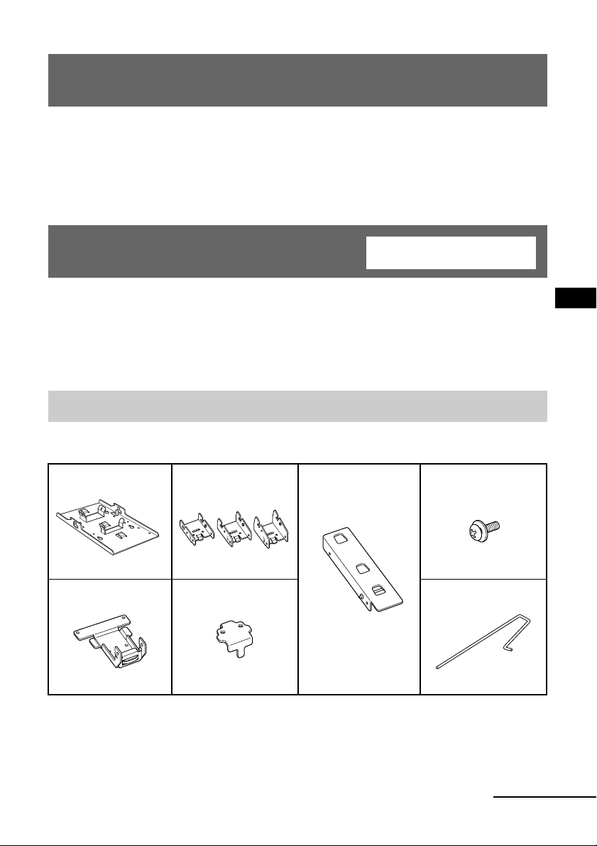
Step 1: Check the parts
Check all the parts are included in the package.
Bracket A (1) Bracket C (3)
(0°, 5°, 10°)
Bracket B (1) Bracket D (1) Locking rod (1)
Bracket E (1) Screw (6)
(with washer)
US
continued
3
Page 4
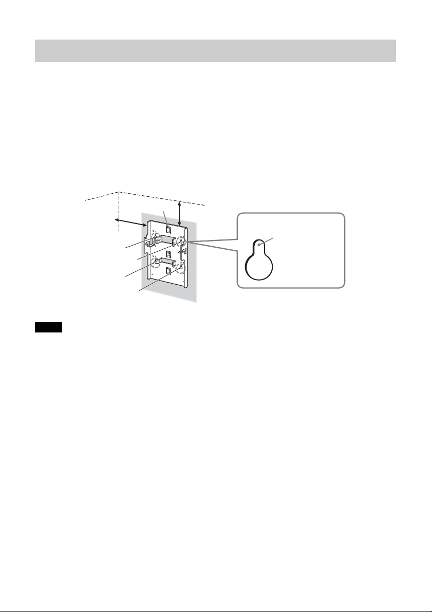
Step 2: Decide the installation location
Decide the location on the wall to install the TV.
Then, place bracket A on the installation location and mark the four screw
holes on the wall using a pencil.
Before marking the location of the holes, make sure that the distance between the
upper edge of bracket A and the ceiling is 15 cm (5 29/32 inches) or more, and that
between the side edge of bracket A and the side wall is 25 cm (9 27/32 inches) or
more.
Ceiling
Bracket A
25 cm (9 27/
inches) or more
32
Note
Attach bracket A level with the floor.
15 cm (5 29/
inches) or more
Wall
32
Mark this
portion using
a pencil.
4
Page 5
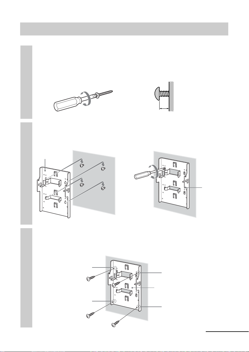
Step 3: Secure bracket A to the wall
Insert four of the screws you prepared at the positions
marked in Step 2 (page 4).
1
Do not tighten the screws completely for the moment. Keep a space of
2 to 3 mm (3/32 to 1/8 inches) from the wall.
Wall
Screws you
prepared
Press bracket A to the wall and slide it down. Then fully
tighten the four screws on the wall.
2
Bracket A
2 - 3 mm (3/32 - 1/8 inches)
,
Wall
Wall
Insert four of the screws you prepared in the screw holes,
and tighten them securely in the order of 1 to 4 as
3
shown below.
1
Screws you
prepared
4
3
Bracket A
2
Bracket A
continued
5
Page 6
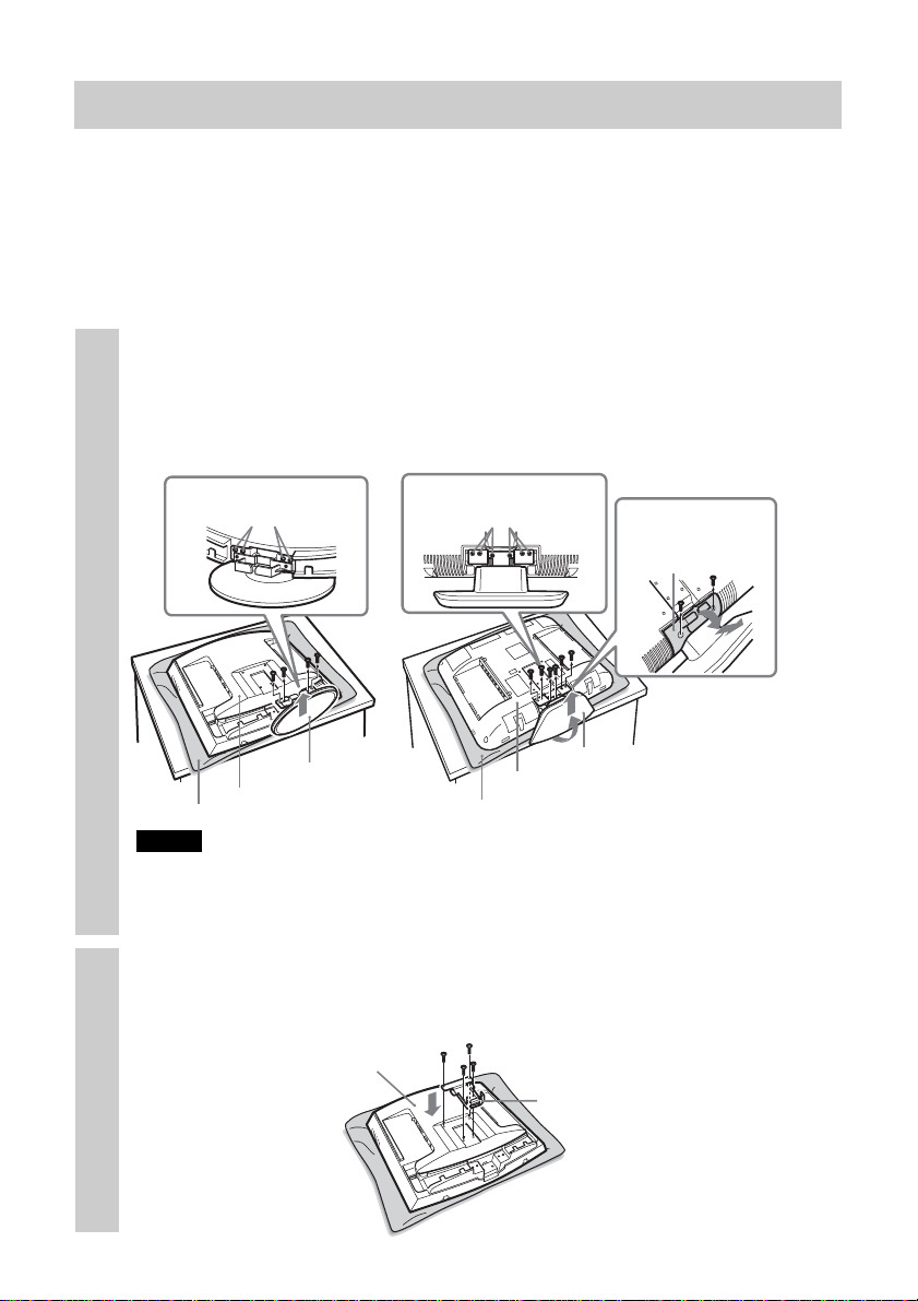
Step 4: Attach bracket B to the TV
Before attaching bracket B, remove the rear cover of the TV and disconnect all
the cables from the TV.
For how to remove the rear cover of the TV, refer to the Operating Instructions
supplied with the TV.
(The illustrations used in this manual show the KLV-21SR2/KLV-23M1 as
examples.)
Remove the screws as shown below, and remove the TV
stand from the TV.
1
To prevent damaging the surface of the LCD display, place the TV on a
soft mat.
Soft mat
Notes
• Place the TV body only on the table as shown above. If the TV stand is also on the
table, the TV body may be unstable and cause damage.
• When removing the TV stand, hold it firmly.
KLV-21SR2
Remove the four
screws.
TV stand
Rear of the TV
Remove the six
screws. (M4 type for
bracket B)
Soft mat
KLV-23M1
TV stand
Rear of the TV
Remove the two
screws and hinge
cover.
To secure bracket B to
the TV, use the screws
removed from the TV
stand, not the ones
from the hinge cover.
Secure bracket B to the TV firmly using the four screws
removed in step 1.
2
Rear of the TV
Bracket B
6
Page 7
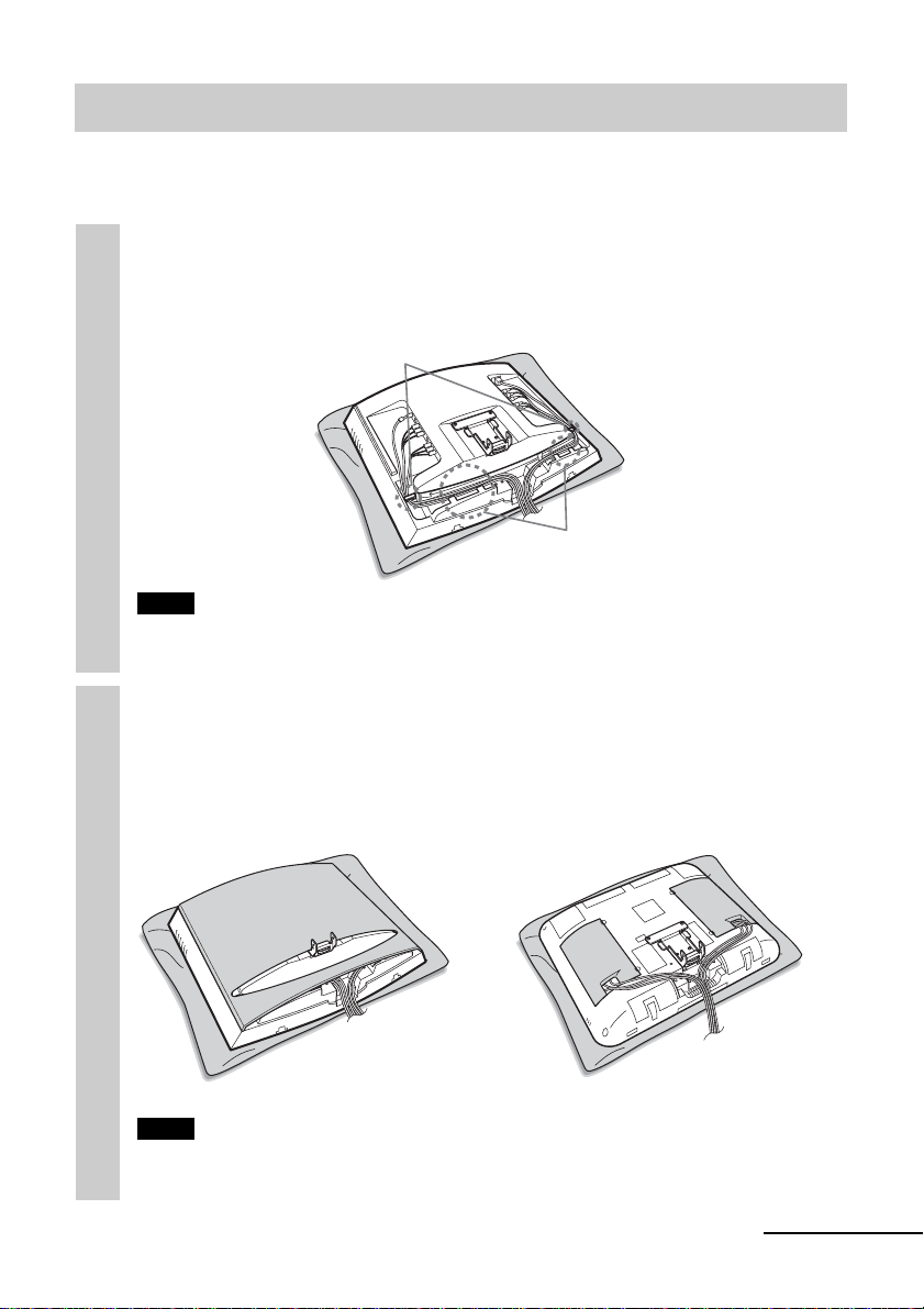
Step 5: Attach the rear cover on the TV
(The illustrations used in this manual show the KLV-21SR2/KLV-23M1 as
examples.)
Connect the cables.
How to connect/bundle the cables differs depending on the TV model.
1
For details, refer to the Operating instruction for your TV.
Clips
Tabs
Note
If the cables are not neatly stored in the grooves, you may not be able to attach the
rear cover.
Attach the rear cover.
For KLV-23M1, attach the cable covers instead of the rear cover.
2
For details on how to attach the rear cover, refer to the Operating
Instructions of the TV.
KLV-21SR2 KLV-23M1
Note
When you attach the rear cover, make sure that bracket B does not damage the rear
cover.
continued
7
Page 8
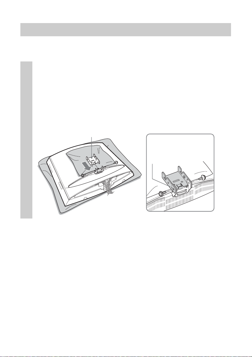
Step 6: Attach brackets C, D, and E to the TV
To prevent damaging the surface of the rear cover of the TV, put a soft mat on
the rear cover.
Attach bracket C of the desired angle to bracket B.
Insert the hooked part of bracket C into bracket B as illustrated below.
1
Confirm that both sides of bracket C are outside bracket B, and secure
them firmly with two of the supplied screws.
There are three types of bracket C, each with a different angle: 0°, 5°,
and 10°. Choose the bracket C with the desired angle to attach.
The illustration below shows an example of how to attach bracket C
with an angle of 0°.
Bracket C
The angle “0°,” “5°,” or
“10°” is marked on the
side of bracket C.
8
Page 9
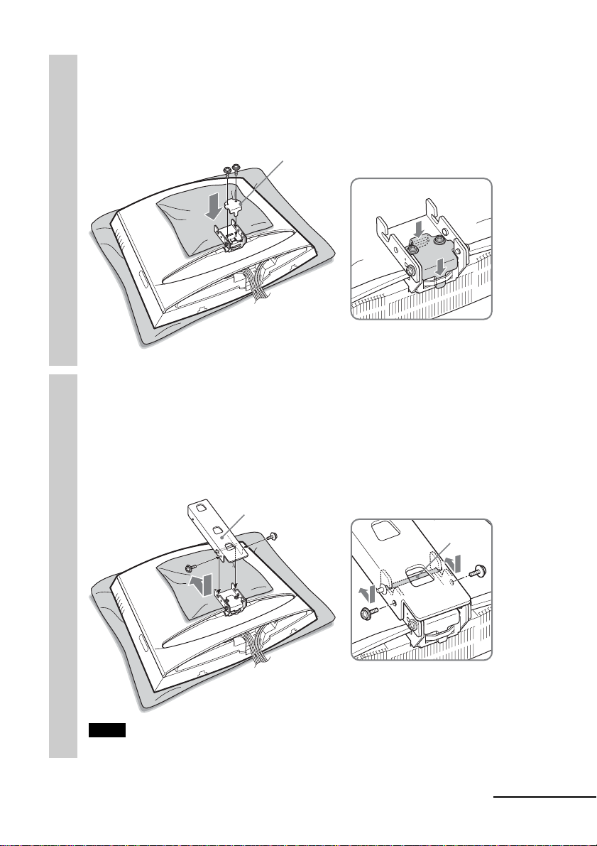
Attach bracket D to bracket C, and secure them firmly
with two of the supplied screws.
2
Place bracket D onto bracket C as illustrated below, and secure them
with the two screws.
Bracket D
Attach bracket E to bracket C, and secure them firmly
with two of the supplied screws.
3
Slide the shaft of bracket E into the notches of bracket C as illustrated
below, and secure them with the two screws one on each side. When you
complete attaching bracket E, remove the soft mat from the rear cover
of the TV.
Bracket E
Shaft
Note
Be careful not to get your fingers caught between the brackets when attaching them.
continued
9
Page 10
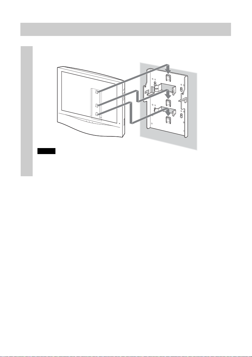
Step 7: Secure the TV to the wall
Hook bracket E on bracket A.
1
Bracket A
Bracket E
Wall
Notes
• Hold the TV firmly. Be especially careful when you secure the TV in a high place.
• Do not release the TV until you confirm that bracket E is firmly secured to bracket
A at three locations.
10
Page 11
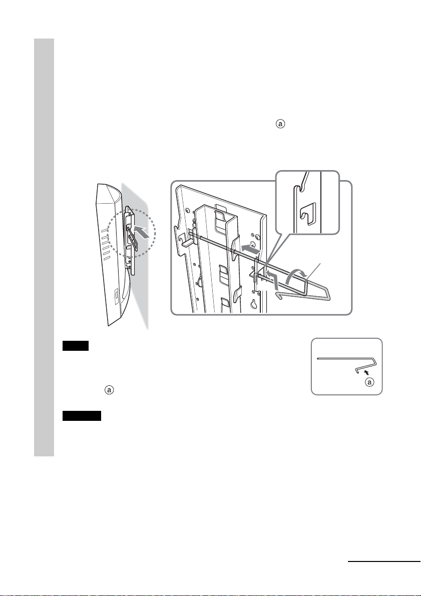
Insert the locking rod.
The locking rod can be inserted from either side. The illustration below
2
shows an example of how to insert the locking rod from the right side.
1 Insert the longer side of the locking rod into the holes on bracket
E.
2 Insert the curved side of the locking rod into the hole on bracket
A. Hold and press the locking rod at part to pass its end
through the hole.
3 Turn the locking rod until it stops to secure it in place.
1
Locking
rod
3
2
Note
To prevent the locking rod from falling out of the brackets, the
space between both ends of the locking rod is greater than that
between the holes on the brackets. Hold and press the locking
rod at part
Caution
If the TV is lifted up when the locking rod is not installed properly, the TV may fall
off the Wall-Mount Bracket and cause serious injury.
Be sure to insert and secure the locking rod in place.
so that it can pass through the holes.
continued
11
Page 12
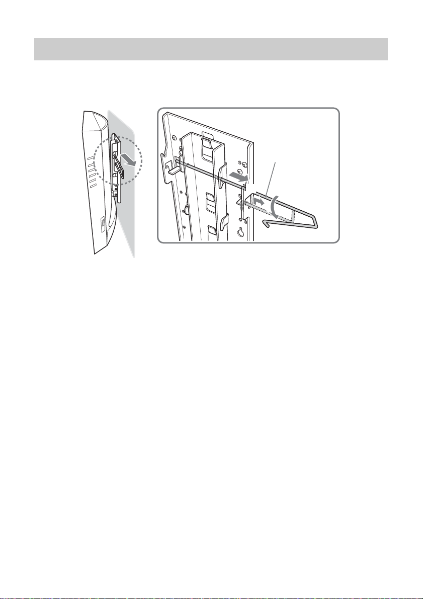
Detaching the TV from the Wall-Mount Bracket
Remove the locking rod from brackets A and E, then detach the TV from the
Wall-Mount Bracket.
3
2
Locking rod
1
12
Page 13

Specifications
inches)
32
/
1
Value varies
depending on the angle
of bracket C.
280 mm (11
168 mm
(6 5/8 inches)
Bracket mass: Approx. 1.6 kg (3 lb 8 oz)
Supportable weight: Approx. 12 kg (26 lb 7 oz)
Design and specifications are subject to change without notice.
Bracket C
angle
0°
5°
10°
55 mm
(2 5/32 inches)
63 mm
(2 15/32 inches)
71 mm
(2 25/32 inches)
13
Page 14

Merci d’avoir fait l’acquisition de ce produit.
A l’attention des utilisateurs
L’installation de ce produit nécessite de bonnes connaissances en matière
de montage, notamment pour s’assurer de la solidité du mur. Confiez la
fixation au mur de ce produit (étapes 1 à 3 de la section « Installation ») aux
revendeurs ou prestataires Sony et veillez particulièrement à la sécurité au
cours de l’installation. Nous déclinons toute responsabilité en cas de
blessures ou de dommages consécutifs à une mauvaise manipulation ou à
une installation incorrecte.
AVERTISSEMENT
Pour réduire les risques de blessure grave ou d’endommagement du téléviseur
suite à sa chute, suivez les précautions suivantes.
•Ne vous tenez pas au téléviseur ou au support de fixation mural du
téléviseur lorsqu’il est fixé au mur.
• Faites attention à ne pas coincer le cordon de l’adaptateur d’alimentation
secteur du téléviseur lorsque vous fixez le téléviseur au support de fixation
mural.
• Suivez les procédures et les instructions d’installation données dans ce mode
d’emploi.
Pour une installation en toute sécurité, demandez assistance à votre
revendeur Sony ou à un technicien agréé de service après vente.
• Avant de commencer l’installation, vérifiez que le mur est suffisamment
résistant pour supporter le téléviseur et le support de fixation mural.
L’emplacement choisi pour l’installation doit être un mur plat, parfaitement
droit et contenant un matériau de renforcement.
•Ne faites pas supporter un poids supérieur à celui du téléviseur au support
de fixation mural une fois qu’il est en place sur le mur.
•Ne démontez pas, ne modifiez pas et ne remplacez pas les pièces du support
de fixation mural pour téléviseur.
A l’attention des revendeurs Sony
L’installation de ce produit nécessite de bonnes connaissances en matière de
montage. Lisez entièrement le mode d’emploi afin d’effectuer une installation
en toute sécurité. Nous déclinons toute responsabilité en cas de blessures ou de
dommages consécutifs à une mauvaise manipulation ou à une installation
incorrecte. Une fois l’installation terminée, remettez le mode d’emploi aux
utilisateurs.
2
Page 15

Attention
• Ce support de fixation mural n’est destiné à être utilisé qu’avec des
téléviseurs couleur LCD de Sony.
N’utilisez pas ce support de fixation mural avec un téléviseur dont le mode
d’emploi ne cite pas l’utilisation de ce support de fixation mural.
• Faites particulièrement attention à ne pas faire tomber le téléviseur lorsque
vous l’installez à une hauteur importante sur le mur.
Installation
A l’attention des revendeurs Sony
Pour l’installation, vous devez disposer de huit vis de montage, boulons
d’ancrage ou autres, disponibles dans le commerce, et adaptés au mur.
Le type et la longueur des vis nécessaires dépendent du matériau et de la
résistance du mur. Si vous ne savez pas de quel matériau votre mur est
constitué, consultez votre revendeur Sony ou un technicien agréé de service
après-vente.
1ère étape : Vérification des pièces
Vérifiez toutes les pièces incluses dans l’emballage.
Support de
fixation A (1)
Support de
fixation B (1)
Support de
fixation C (3)
(0°, 5°, 10°)
Support de
fixation D (1)
Support de
fixation E (1)
Vis (6)
(avec rondelle)
Tige de blocage (1)
FR
suite à la page suivante
3
Page 16

2ème étape : Choix de l’emplacement
d’installation
Choisissez l’emplacement sur le mur où vous allez installer le téléviseur.
Puis, placez le support de fixation A sur l’emplacement d’installation et
marquez l’emplacement des quatre orifices des vis sur le mur avec un crayon.
Avant de marquer l’emplacement des trous, assurez-vous que la distance entre
le bord supérieur du support de fixation A et le plafond est d’au moins 15 cm
(5 29/32 pouces), et que celle entre le bord latéral du support de fixation A et le
mur latéral est d’au moins 25 cm (9 27/32 pouces).
Plafond
Support de
fixation A
Au moins 25 cm
(9 27/32 pouces)
Remarque
Fixez le support de fixation A de façon à ce qu’il soit parallèle au sol.
Au moins 15 cm
(5 29/32 pouces)
Mur
Marquez cette
portion à l’aide
d’un crayon.
4
Page 17

3éme étape : Fixation du support de fixation
A au mur
Insérez quatre des vis que vous avez préparées dans les
positions marquées à l’étape 2 (page 4).
1
Ne serrez pas les vis à fond pour le moment. Gardez un espace de
2 ou 3 mm (3/32 ou 1/8 pouces) par rapport au mur.
Mur
Vis que vous
avez préparées
Appuyez le support de fixation A contre le mur et faites-le
glisser vers le bas. Puis serrez à fond les quatre vis sur le mur.
2
Support de
fixation A
,
2 à 3 mm (3/32 à 1/8 pouces)
Support de
fixation A
Mur
Mur
Insérez quatre des vis que vous avez préparées dans les
trous prévus à cet effet, puis vissez-les à fond dans l’ordre
3
de 1 à 4 comme indiqué ci-dessous.
1
Vis que vous
avez préparées
4
3
Support de fixation A
2
suite à la page suivante
5
Page 18

4ème étape : Fixation du support de fixation
B au téléviseur
Avant de fixer le support de fixation B, retirez l’arrière du téléviseur et
débranchez tous les câbles du téléviseur.
Pour plus de détails sur la façon de retirer le panneau arrière du téléviseur,
reportez-vous au mode d’emploi fourni avec le téléviseur.
(Les illustrations de ce manuel représentent les modèles KLV-21SR2/KLV-23M1
à titre d’exemple.)
Retirez les vis ainsi qu’il est indiqué dans l’illustration et
détachez le support du téléviseur.
1
Afin de ne pas endommager la surface de l’écran LCD, placez le
téléviseur sur un tissu doux.
KLV-21SR2
Retirez les quatre vis
Retirez les six vis. (de
type M4 pour le support
B)
KLV-23M1
Retirez les deux
vis et le panneau
recouvrant les
charnières.
Support du téléviseur
Tissu doux
Remarques
• Placez uniquement le corps du téléviseur sur la table comme illustré ci-dessus. Si le
support du téléviseur se trouve également sur la table, le corps du téléviseur risque
d’être instable et pourrait provoquer des dommages.
• Lorsque vous retirez le support du téléviseur, tenez-le fermement.
Fixez fermement le
support de fixation B au
2
Arrière du téléviseur
Afin de fixer correctement le support B au téléviseur,
utilisez les vis que vous avez retirées du support du
téléviseur et non celles du panneau recouvrant les
charnières.
Arrière du téléviseur
Tissu doux
Support du téléviseur
Arrière du téléviseur
téléviseur à l’aide des
quatre vis retirées à
l’étape 1.
6
Support de
fixation B
Page 19

5ème étape : Fixation du panneau arrière sur
le téléviseur
(Les illustrations de ce manuel représentent les modèles KLV-21SR2/KLV-23M1
à titre d’exemple.)
Raccordez les câbles.
La façon de raccorder/regrouper les câbles varie selon le modèle du
1
téléviseur. Pour plus de détails, reportez-vous au Mode d’emploi de
votre téléviseur.
Remarque
Si les câbles ne sont pas correctement rangés dans les rainures, cela risque de vous
empêcher de fixer le panneau arrière du téléviseur.
Fixez le panneau arrière.
Pour le modèle KLV-23M1, fixez la protection des câbles au lieu du
2
panneau arrière.
Pour plus de détails sur la fixation du panneau arrière, reportez-vous au
Mode d’emploi de votre téléviseur.
KLV-21SR2 KLV-23M1
Colliers
Languettes
Remarque
Lorsque vous fixez le panneau arrière, veillez à ce que le support B ne l’endommage
pas.
suite à la page suivante
7
Page 20

6ème étape : Pose des supports de fixation
C, D et E sur le téléviseur
Afin de ne pas endommager la surface du panneau arrière du téléviseur, placez
ce dernier sur un tissu doux.
Fixez le support de fixation C au support de fixation B
selon l’angle souhaité.
1
Insérez la partie en crochet du support de fixation C dans le support de
fixation B comme illustré ci-dessous. Vérifiez que les deux côtés du
support de fixation C sont à l’extérieur du support de fixation B et
vissez-les à fond avec les deux vis fournies.
Il existe trois types de support de fixation C, chacun ayant un angle
différent : 0°, 5° et 10°. Choisissez le support de fixation C
correspondant à l’angle souhaité.
L’illustration ci-dessous montre comment fixer le support de fixation C
avec un angle de 0°.
Support de fixation C
L’angle est gravé sur le
côté du support de
fixation C (0°, 5° ou 10°).
8
Page 21

Fixez le support de fixation D au support de fixation C en
vissant à fond deux des vis fournies.
2
Placez le support de fixation D dans le support de fixation C, comme
illustré ci-dessous, et vissez à fond les deux vis.
Support de fixation D
Fixez le support de fixation E au support de fixation C en
vissant à fond deux des vis fournies.
3
Faites glisser l’axe du support de fixation E dans les encoches du
support de fixation C, comme illustré ci-dessous, et vissez à fond les
deux vis de chaque côté. Une fois le montage du support de fixation E
terminé, retirez le tissu doux du panneau arrière du téléviseur.
Support de
fixation E
Axe
Remarque
Faites attention à ne pas vous coincer les doigts dans les supports de fixation au
moment de leur fixation.
suite à la page suivante
9
Page 22

7ème étape : Fixation du téléviseur au mur
Accrochez le support de fixation E au support de fixation
A.
1
Support de
fixation A
Support de
fixation E
Mur
Remarques
• Tenez fermement le téléviseur. Faites particulièrement attention lorsque vous fixez
le téléviseur à un endroit élevé.
• Ne relâchez pas le téléviseur avant de vous être assuré que le support de fixation E
est solidement fixé au support de fixation A aux trois emplacements indiqués cidessus.
10
Page 23

Insérez la tige de blocage.
La tige de blocage peut être insérée du côté droit ou du côté gauche.
2
L’illustration ci-dessous montre la mise en place de la tige de blocage du
côté droit.
1 Insérez la partie la plus longue de la tige de blocage dans les
orifices du support de fixation E.
2 Insérez la partie recourbée de la tige de blocage dans l’orifice du
support de fixation A. Appuyez sur la partie de la tige et
maintenez-la enfoncée pour faire passer l’extrémité dans
l’orifice.
3 Faites pivoter la tige jusqu’à ce qu’elle se bloque.
1
Tige de
blocage
3
2
Remarque
Pour empêcher que la tige de blocage ne tombe des supports
de fixation, l’espace entre les deux extrémités de la tige est
supérieur à celui entre les orifices sur les supports de fixation.
Appuyez sur la partie
pour la faire passer dans les orifices.
Attention
Si vous soulevez le téléviseur et que la tige de blocage n’est pas installée
correctement, le téléviseur risque de tomber du support de fixation mural et de
blesser gravement des personnes.
N’oubliez pas d’insérer la tige de blocage et de bien la fixer.
de la tige et maintenez-la enfoncée
suite à la page suivante
11
Page 24

Retrait du téléviseur du support de fixation
mural
Retirez la tige de blocage des supports de fixation A et E, puis déposez le
téléviseur du support de fixation mural.
3
Tige de blocage
2
1
12
Page 25

Spécifications
La valeur dépend de
pouces)
32
/
1
280 mm (11
168 mm
(6 5/8 pouces)
Poids du support de fixation : Environ 1,6 kg (3 lb 8 oz)
Poids pouvant être supporté : Environ 12 kg (26 lb 7 oz)
La conception et les spécifications sont sujettes à modification sans préavis.
l’angle du support de
fixation C.
Angle du
support
de
fixation C
0°
5°
10°
55 mm
(2 5/32 pouces)
63 mm
(2 15/32 pouces)
71 mm
(2 25/32 pouces)
13
Page 26

Gracias por adquirir este producto.
Para clientes
Se requiere suficiente experiencia para instalar este producto,
especialmente para asegurar la resistencia de la pared. Acuda a
distribuidores o contratistas de Sony para realizar la instalación de este
producto en la pared (pasos 1 a 3 del apartado “Instalación”) y preste
especial atención a la seguridad durante la instalación. Declinamos
cualquier responsabilidad por los daños o heridas producidos por una
manipulación incorrecta o una instalación inadecuada.
ADVERTENCIA
Para evitar el riesgo de caídas que puedan provocar lesiones o daños graves en
el televisor, tome las siguientes precauciones.
•No se apoye en el televisor ni en el soporte de montaje mural instalado en la
pared.
• Asegúrese de no atrapar el cable del adaptador de alimentación de CA del
televisor al fijar el televisor al soporte de montaje mural.
• Siga los procedimientos e instrucciones de instalación descritos en el presente
manual.
Para garantizar la seguridad de la instalación, póngase en contacto con su
distribuidor Sony o con personal de servicio técnico cualificado.
• Antes de realizar la instalación, compruebe que la pared sea lo
suficientemente resistente como para sostener el televisor y el soporte de
montaje mural. La instalación debe realizarse en una pared plana,
perpendicular y con material de refuerzo en el interior.
•No aplique un peso que no sea el del televisor en el soporte de montaje mural
instalado en la pared.
•No desmonte, modifique ni cambie las piezas del soporte de montaje mural.
Para distribuidores Sony
Se requiere suficiente experiencia para instalar este producto. Asegúrese de
leer detenidamente este manual de instrucciones para poder realizar con
seguridad el proceso de instalación. Declinamos cualquier responsabilidad por
los daños o heridas producidos por una manipulación incorrecta o una
instalación inadecuada. Después de la instalación, entregue este manual de
instrucciones a los clientes.
2
Page 27

Precauciones
• Este soporte de montaje mural de televisor está destinado exclusivamente
para televisores en color de pantalla de cristal líquido de Sony.
No utilice el soporte con un televisor en cuyas instrucciones no se especifique
explícitamente la utilización de este soporte.
• Tenga especial cuidado para evitar la caída del televisor cuando lo instale en
alto en una pared.
Instalación
Para la instalación, prepare ocho tornillos de montaje, pernos de anclaje, etc.
disponibles en el mercado que sean adecuados para la pared.
El tipo y medida de los tornillos necesarios dependen del material y la
resistencia de la pared. Si desconoce con qué material está construida la pared,
póngase en contacto con su distribuidor Sony o con personal de servicio
técnico cualificado.
Para distribuidores Sony
Paso 1: Compruebe las piezas
Compruebe que el paquete contenga todas las piezas.
Soporte A (1)
Soporte B (1) Soporte D (1) Barra de bloqueo (1)
Soporte C (3)
(0°, 5°, 10°)
Soporte E (1)
Tornillo (6)
(con arandela)
ES
continúa
3
Page 28

Paso 2: Elija el sitio para la instalación
Decida en qué parte de la pared desea instalar el televisor.
A continuación, sitúe el soporte A donde realizará la instalación y marque en
la pared con un lápiz los cuatro orificios para los tornillos.
Antes de marcar la ubicación de los orificios, compruebe que la distancia entre
el extremo superior del soporte A y el techo es de 15 cm (5 29/32 pulgadas) o
más, y de que la distancia entre el extremo lateral del soporte A y la pared
contigua sea igual o superior a 25 cm (9 27/32 pulgadas).
Techo
25 cm (9 27/
pulgadas) o más
32
Soporte A
15 cm
pulgadas)
Pared
Nota
Ajuste el nivel del soporte A con el suelo.
(5 29/
o más
32
Marque esta
zona con un
lápiz.
4
Page 29

Paso 3: Fije el soporte A a la pared
Introduzca cuatro de los tornillos preparados en las
posiciones marcadas en el paso 2 (página 4).
1
De momento, no apriete los tornillos completamente. Deje un espacio de
2 a 3 mm (3/32 a 1/8 pulgadas) entre ellos y la pared.
Pared
Tornillos
preparados
Presione el soporte A contra la pared y deslícelo hacia
abajo. A continuación, apriete completamente los cuatro
2
tornillos en la pared.
Soporte A
2 - 3 mm (3/32 - 1/8 pulgadas)
,
Pared
Introduzca cuatro de los tornillos preparados en los
orificios de los tornillos y apriételos firmemente en el
3
orden de 1 a 4 tal como se muestra a continuación.
1
Tornillos
preparados
4
3
Soporte A
2
Soporte A
Pared
continúa
5
Page 30

Paso 4: Fije el soporte B al televisor
Antes de fijar el soporte B, retire la cubierta posterior del televisor y
desconecte todos los cables del televisor.
Para obtener instrucciones sobre cómo retirar la cubierta posterior del televisor,
consulte el manual de instrucciones suministrado con el televisor.
(Las ilustraciones incluidas en este manual utilizan los modelos KLV-21SR2/
KLV-23M1 como ejemplo).
Extraiga los tornillos como se indica a continuación y retire
el soporte del televisor.
1
Para evitar posibles daños en la superficie de la pantalla de cristal
líquido, sitúe el televisor sobre una esterilla blanda.
KLV-21SR2
Extraiga los cuatro
tornillos.
Extraiga los seis
tornillos. (tipo M4 para
el soporte B)
KLV-23M1
Extraiga los dos
tornillos y la
cubierta de la
bisagra.
2
6
Soporte de televisor
Esterilla blanda
Parte posterior del televisor
Notas
• Coloque únicamente el televisor encima de la mesa como se indica arriba. Si
también coloca el soporte del televisor, el equipo puede desestabilizarse y provocar
daños o lesiones.
• Al retirar el soporte de televisor, sujételo con firmeza.
Fije firmemente el
Esterilla blanda
Para fijar el soporte B al televisor, utilice los
tornillos que ha extraído del soporte del
televisor y no los de la cubierta de la bisagra.
Parte posterior del
televisor
Parte posterior del televisor
soporte B al televisor
Soporte de televisor
Soporte B
mediante los cuatro
tornillos
desenroscados en el
paso 1.
Page 31

Paso 5: Coloque la cubierta posterior en el
televisor
(Las ilustraciones incluidas en este manual utilizan los modelos KLV-21SR2/
KLV-23M1 como ejemplo).
Conecte los cables.
La manera de conectar o agrupar los cables puede variar según el
1
modelo de televisor. Para obtener más información, consulte el manual
de instrucciones del televisor.
Pinzas
Lengüetas
Nota
Si los cables no se colocan correctamente en las ranuras, es posible que no pueda
colocar la cubierta posterior.
Coloque la cubierta posterior.
En el modelo KLV-23M1, coloque las cubiertas de los cables en lugar de
2
la cubierta posterior.
Para obtener más información acerca de la colocación de la cubierta
posterior, consulte el manual de instrucciones del televisor.
KLV-21SR2
KLV-23M1
Nota
Cuando coloque la cubierta posterior, asegúrese de que el soporte B no puede
provocar ningún daño en la cubierta posterior.
continúa
7
Page 32

Paso 6: Fije los soportes C, D y E al televisor
Para evitar que la superficie de la cubierta posterior del televisor se dañe,
coloque una esterilla blanda sobre ella.
Fije el soporte C del ángulo que desee al soporte B.
Inserte la parte en forma de gancho del soporte C en el soporte B tal
1
como se ilustra a continuación. Compruebe que los dos lados del soporte
C están fuera del soporte B y fíjelos firmemente con dos de los tornillos
suministrados.
Hay tres tipos de soporte C, cada uno con un ángulo diferente: 0°, 5° y
10°. Elija el soporte C con el ángulo que desee para fijarlo.
La siguiente ilustración muestra un ejemplo de cómo fijar el soporte C
con un ángulo de 0°.
Soporte C
El ángulo “0°”, “5°” o
“10°” está marcado en
el lado del soporte C.
8
Page 33

Fije el soporte D al soporte C y sujételos firmemente con
dos de los tornillos suministrados.
2
Coloque el soporte D sobre el soporte C tal como se ilustra a
continuación y fíjelos firmemente con los dos tornillos.
Soporte D
Fije el soporte E al soporte C y sujételos firmemente con
dos de los tornillos suministrados.
3
Deslice el eje del soporte E dentro de las muescas del soporte C tal
como se ilustra a continuación y fíjelo firmemente con los dos tornillos,
uno en cada lado. Cuando termine de fijar el soporte E, retire la esterilla
blanda de la cubierta posterior del televisor.
Soporte E
Eje
Nota
Tenga cuidado de no pillarse los dedos entre los soportes cuando los fije.
continúa
9
Page 34

Paso 7: Fije el televisor a la pared
Enganche el soporte E al soporte A.
1
Soporte A
Soporte E
Pared
Notas
• Sujete firmemente el televisor. Tenga especial cuidado al fijar el televisor en un sitio
elevado.
• No suelte el televisor hasta que compruebe que el soporte E está firmemente sujeto
al soporte A en las tres ubicaciones.
10
Page 35

Introduzca la barra de bloqueo.
La barra de bloqueo puede introducirse desde ambos lados. La siguiente
2
ilustración muestra un ejemplo de cómo introducir la barra de bloqueo
desde el lado derecho.
1 Introduzca el lado más largo de la barra de bloqueo en los
orificios del soporte E.
2 Introduzca el lado curvado de la barra de bloqueo en el orificio
del soporte A. Sujete la barra de bloqueo y presiónela en la
parte para pasar el extremo a través del orificio.
3 Gire la barra de bloqueo hasta que se detenga para fijarla en su
posición.
1
Barra de
bloqueo
3
2
Nota
Para evitar que la barra de bloqueo se salga de los soportes, el
espacio entre ambos extremos de la barra es mayor que el
espacio entre los orificios de los soportes. Sujete la barra de
bloqueo y presiónela en la parte
por los orificios.
Precaución
Si se levanta el televisor cuando la barra de bloqueo no está instalada correctamente,
la unidad podría caerse del soporte de montaje mural y provocar lesiones graves.
Asegúrese de introducir y fijar la barra de bloqueo en su posición.
de forma que pueda pasar
continúa
11
Page 36

Retirar el televisor del soporte de montaje
mural
Retire la barra de bloqueo de los soportes A y E y, a continuación, separe el
televisor del soporte de montaje mural.
3
Barra de bloqueo
2
1
12
Page 37

Especificaciones
El valor varía según el
pulgadas)
32
/
1
280 mm (11
168 mm
(6 5/8 pulgadas)
Peso del soporte: 1,6 kg (3 libras 8 onzas) aprox.
Peso soportable: 12 kg (26 libras 7 onzas) aprox.
El diseño y las especificaciones están sujetos a cambios sin previo aviso.
ángulo del soporte C.
Ángulo
del
soporte C
0°
5°
10°
55 mm
(2 5/32 pulgadas
63 mm
(2 15/32 pulgadas
71 mm
(2 25/32 pulgadas
)
)
)
13
Page 38

Page 39

Page 40

Printed on 100% recycled paper.
Printed in Japan
 Loading...