

Page 1
TV STAND/SOPORTE DEL TELEVISOR
MEUBLE DE TELEVISION
INSTRUCTIONS
The SU-36XBR7 TV stand is designed for use only with Sony 36-inch
TV sets listed to the right.
INSTRUCCIONES
Este soporte de televisor SU-36XBR7 ha sido diseñado para ser usado
solamente con los televisores Sony de 36” notados a la derecha.
SU-36XBR8
SU-36XBR8:
KV-36XBR700
INSTRUCTIONS
Le meuble de télévision SU-36XBR7 TV est conçu pour être
utilisé avec un téléviseur Sony de 92 cm (36 pouces).
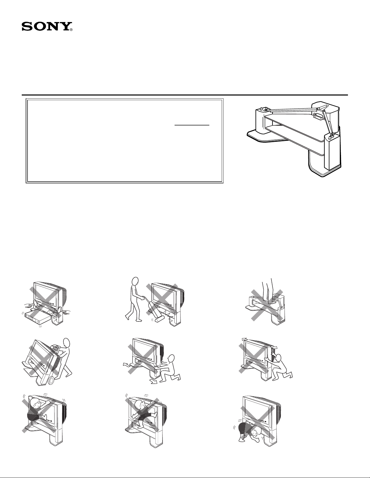
● Do not place the stand in a location near a
NOTES ON USE
heat source, such as a radiator, or in a place
subject to di rect sunlight.
● Clean the stand periodically with a soft cloth.
If fi nger prints, food and beverage stains, etc.,
are dif fi cult to remove, use a cloth moistened
with a mild detergent solution. Do not use a
scouring powder, abrasive pad or sol vent.
NOTAS ACERCA DEL USO
● No instale el soporte de televisor en un lugar cerca
de un fuente de calor, tal como un radiador, ni
tampoco bajo la luz directa del sol.
● Limpie el mueble periodicamente con un paño
suave. Si tiene difi cultad para eliminar huellas
dactilares, manchas de comida o de bebida use un
paño mojado en una solución detergente suave.
No utilice polvos o esponjas abrasivas, ni tampoco
solventes.
WARNING / ADVERTENCIA / AVERTISSEMENT
Do not give the glass shelf
a sudden shock.
No le de una sacudida
brusca a la repisa de
vidrio.
Ne pas soumettre
l’étagére en verre á un
choc brusque.
ASSEMBLED STAND
SOPORTE ENSAMBLADO
MEUBLE ASSEMBLÉ
Do not hit edge of glass
shelf with a vacuum
cleaner
No golpear la orilla de la
repisa de vidrio con una
aspiradora
Ne pas heurter le rebord
de l’étagére en verre avec
un aspirateur.
● N’installez pas le meuble à proximité d’une
NOTES D’EMPLOI
source de chaleur, notamment un radiateur, ou dans
un endroit exposé aux rayons directs du soleil.
● Nettoyez régulièrement le meuble avec un chiffon
doux. S’il est diffi cile de faire disparaître des
empreintes, des taches de boisson ou d’aliments,
par exem ple, utilisez un chiffon humide et une
solution à base de détergent do ux. N’utili
sez pas de poudre à récurer, de tampon abrasif
ou de solvant.
Do not stand on the TV
stand or the glass shelf
No se pare sobre el
soporte del televisor o
sobre la repisa de vidrio.
Ne pas monter sur le
meuble de télévision ou
sur l’etagere en verre.
Do not use dolly.
No usar diablito.
Ne pas utiliser un diable.
To avoid serious injury, do
not allow children to hang
from the television set.
Para evitar lesiones
severas, no permita que
los niños se cuelguen del
conjunto del televisor.
Pour éviter les blessures
graves, ne laissez aucun
enfant s’accrocher au
téléviseur.
© 2002 by Sony Electronics Inc.
Do not push/pull on legs
of TV stand.
No empujar o jalar sobre
los pilares de el soporte
de televisor.
Ne pas pousser/tirer sur
les jambes du meuble de
télévision.
To avoid injury to the user
and damage to the stand, do
not use the shelf as a step.
Para evitar lesiones al
usuario y daño al mueble, no
use la repisa como escalon.
Pour éviter que l’utilisateur se
blesse et que le meuble soit
endommagé, ne l’utilisez pas
comme marchepied.
1
Do not push/pull TV set.
No empujar o jalar
televisor.
Ne pas pousser/tirer le
téléviseur.
Do not allow children to crawl
under/between glass shelves.
No permita que los niños se
arrastren bajo/entre las repisas
de vidrio.
Ne pas laisser les enfants ramper
sous ou entre les étagéres en
verre.
Page 2
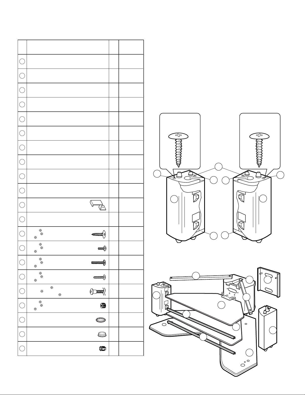
PARTS LIST MODEL : SU-36XBR8
LISTA DE PARTES MODELO : SU-36XBR8
LISTE DES PIÈCES MODÈLE : SU-36XBR8
Item
Description
Artículo
Descripción
Article
Description
Base board
Base inferior
1
Panneau inférieur
Rear column
Columna trasera
2
Colonne arrière
Rear column cover
Cubierta de la columna posterior
3
Couvercle de colonne arrière
Side pillar (Right) (pre-assembled)
Pilar lateral (Derecho) (pre-ensamblado)
4
Pilier latéral (Droit) (pré-assemblage)
Side pillar (Left) (pre-assembled)
Pilar lateral (Izquierdo) (pre-ensamblado)
5
Pilier latéral (Gauche) (pré-assemblage)
Core cap A (pre-assembled)
Tapa interior A (pre-ensamblado)
6
Capuchon A (pré-assemblage)
Core cap B (pre-assembled)
Tapa interior B (pre-ensamblado)
7
Capuchon B (pré-assemblage)
Glass shelf
Repisa de vidrio
8
Étagère en verre
Steel bridge
Puente metalico
9
Traverse en acier
Aluminum frame
Marco de aluminio
10
Cadre en aluminium
Band metal
Banda metalica
A
Bande métallique
Glass bracket (pre-installed)
Sostén de vidrio (preinstalada)
B
Support en verre (pré-installée)
Screw M5x20 (Silver) (pre-installed)
Tornillo M5x20 (Plato) (pre-instalada)
C
Vis M5x20 (Argentée) (pré-installée)
Screw M4x10
Tornillo M4x10
D
Vis M4x10
Screw M5x20 (Black)
Tornillo M5x20 (Negro)
E
Vis M5x20 (Noir)
Screw M4x16
Tornillo M4x16
F
Vis M4x16
M8x448.8
M8x448.8
M8x448.8
Capnut screw
Tornillo
G
Vis d’écrou borgne
Screw M8x8 (pre-installed)
Tornillo M8x8 (pre-instalada)
H
Vis M8x8 (pré-installée)
Toothed lock washer (M12)
Arandela de llave (M12)
I
Rondelle de blocage dentée (M 12)
Rubber Bumper (pre-installed)
Tope de plastico (pre-instalada)
J
Plaque emboîtable (pré-installée)
Insert nut M8x23 (pre-installed)
Rosca integrada M8x23 (pre-instalada)
K
Écrou insert M8x23 (pré-installée)
Qty
Cant
Qté
1
1
1
1
1
2
2
2
2
2
1
2
8
4
4
3
4
4
4
8
4
Part No.
No.parte
N° de pièce
XW2922
P0260
P0261
XP0104
XP0103
P0258
P0259
G0359
M0227
M0215
M0218
M0207
S0137
S0143
S0142
S0122
XS0223
S0063
S0135
P0243
B0093
SIDE PILLAR (LEFT)
PILAR LATERAL (IZQUIERDO)
PILIER LATÉRAL (GAUCHE)
SILVER
PLATO
ARGENTÉE
C
5
(pre-assembled)
(pre-ensamblado)
(pré-assemblage)
5
9
10
SIDE PILLAR (RIGHT)
PILAR LATERAL (DERECHO)
PILIER LATÉRAL (DROIT)
SILVER
PLATO
ARGENTÉE
C
C
6
7
4
6
7
32
10
8
8
4
9
1
(pre-assembled)
(pre-ensamblado)
(pré-assemblage)
2
Page 3
NOTES ON ASSEMBLY
● You will need a medium size Phillips head screwdriver.
● Assemble the stand only by the method shown in this
instruction sheet.
● Assemble the stand near the location where the stand will be used.
● The circled letters in the illustrations are the same as those in the “PARTS LIST”.
For easier as sem bly, line up the parts in the order they will be required.
● Retain this manual for future reference.
NOTAS ACERCA DEL MONTAJE
● Usted necesitará un desarmador mediano de cruz.
● Ensamble el soporte de televisor siguiendo unicamente el metodo mostrado en
estas instrucciones.
● Haga el montaje cerca del lugar donde se usará.
● Las letras encerradas en círculo en las ilustraciones, son las mismas letras en la
“LISTA DE PARTES”. Para facilitar el montaje alinie las partes en el orden en
que serán usadas.
● Conserve este manual para referencia futura
NOTES D’ASSEMBLAGE
● Vous aurez besoin d’un tournevis cruciforme de taille moyenne.
● Assemblez le meuble uniquement selon la méthode décrite dans ce mode d’emploi.
● Assemblez le meuble près de l’endroit où il sera utilisé.
● Les lettres entourées dans les schémas sont les mêmes que celles fi gurant dans la
liste « LISTE DES PIÈCES ». Afi n de faciliter l’assemblage, alignez les pièces par
ordre de montage.
● Gardez ce manuel pour référence ultérieure.
REPLACEMENT PARTS INFORMATION
Review parts list before assembly.
Please examine all packing material before discarding.
If any parts are missing or damaged, identify and refer to
the instructions on the warranty page
To purchase replacement parts only, call the telephone
number listed below.
1-619-661-6136 for residents of the United States.
INFORMACION PARA PARTES DE REEMPLAZO
Revise la lista de partes antes de ensamblar.
Por favor examine el contenido del empaque antes de tirarlo.
Si alguna parte falta o esta dañada, identifi quela y siga las
instrucciones en la hoja de garantÉa.
Para ordenar partes de reemplazo, llame al tel.
1-619-661-6136 para residentes de los Estados Unidos.
(TV stand parts only)
.
(Solo para soporte de TV)
INFORMATIONS SUR LES PIíCES DE RECHA NGE
(Concernent uniquement le meuble de télévision)
Vérifi ez toutes les pièces avant l’assemblage.
Veuillez examiner tous les emballages avant de les jeter.
Si certaines pièces sont manquantes ou défectueuses, reportez-vous
Pour l’achat de pièces de rechange uniquement, appelez le numéro
aux instructions de la page de garantie.
ci-dessous.
1-619-661-6136 pour les habitants des États-Unis.
Hold by marked ( ) locations
➛
when moving TV stand.
Sostener de locaciones mar ca das
➛
( ) cuando mueva el soporte de
televisor.
Soutenir aux endroits marqués
➛
( ) lorsque vous de déplacez le
meuble de télévision.
1
K x 4
(pre-installed)
(pre-instalada)
(pré-installée)
CAUTION: Remove TV set before moving set/stand. Do not move with TV set
fi xed to TV stand. Remove the metal band prior to moving TV onto/off stand.
Move by holding baseboard. Do not lift by support bars and glass shelves.
PRECAUCION: Remover el televisor antes de mover el mueble. No mover con el
televisor instalado. Quite la banda metalica antes de mover el televisor hacia/fuera
del estante. Muevase sosteniendo la base inferior. No levantar por las barras de
soporte y repisa de vidrio.
ATTENTION: Retirer le téléviseur avant de déplacer le meuble de té lé vi sion. Ne
pas deplacer avec le téléviseur fi xe sur le meuble de télévision. Déposez la bande
métallique avant de mettre la télévision sur le meuble ou de l’enlever. Deplacezvous en tenant de base le panneau. Ne soulevez pas avec les barres de support
et l’étagères en verre.
Arrow direction shows front.
La dirección de la fl echa indica el frente.
La direction de la fl èche indique le devant.
2
INSERT REAR COLUMN 2 INTO BASE BOARD 1 .
INSERTE LA COLUMNA POSTERIOR 2 EN LA TABLA BASE 1 .
INSÉREZ LA COLONNE ARRIÈRE 2 DANS LA PLANCHE
DE BASE 1 .
GRAY SURFACE
SUPERFICIE GRIS
SURFACE GRISE
1
3
Page 4
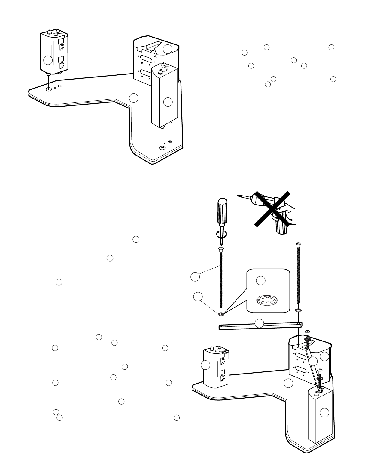
2
3
2
5
1
4
INSERT SIDE PILLAR RIGHT 4 AND SIDE PILLAR LEFT 5
INTO BASE BOARD 1 AS SHOWN.
INSERTE EL PILAR LATERAL DERECHO 4 Y EL PILAR
LATERAL IZQUIERDO 5 EN LA TABLA BASE 1 COMO SE
MUESTRA.
INTRODUISEZ LE PILIER DROIT 4 ET LE PILIER GAUCHE 5
DANS LA PLANCHE DE BASE 1 COMME INDIQUÉ.
CORRECT
CORRECTO
CORRECT
INCORRECT
INCORRECTO
INCORRECT
WHEN TIGHTENING THE CAPNUT SCREW G ,
PLEASE USE A PHILLIPS HEAD SCREWDRIVER.
DO NOT USE AN ELEC TRIC SCREW DRIV ER.
CUADO APRIETE EL TORNILLO G , POR FAVOR
USE UN DESARMADOR DE CRUZ. NO UTILIZE
UN DESARMADOR ELÉCTRICO.
LORS DU SERRAGE DE LA VIS DE L’ÉCROU
BORGNE G , UTILISER UN TOURNEVIS À
TÊTE CRUCIFORME. NE PAS UTILISER DE
TOUR NE VIS ÉLECTRIQUE.
PLACE ALUMINUM FRAMES 10 X 2 INTO RECESSED AREAS AS
SHOWN. INSERT CAPNUT SCREW G THROUGH TOOTHED LOCK
WASHER I FIRST, THEN THROUGH ALU MI NUM FRAME 10 AS
SHOWN AT 4 PLACES.
TIGHTEN USING PHILLIPS HEAD SCREW DRIV ER.
COLOQUE LOS MARCOS DE ALUMINIO 10 X 2 DENTRO DE LAS
AREAS REBAJADAS COMO SE MUESTRA. PRIMERO INSERTE UN
TORNILLO DE CABEZA REDONDA G ATRAVEZ DE UNA RONDANA
DENTADA I , LUEGO ATRAVEZ DEL MARCO DE ALUMINIO 10 EN 4
LUGARES COMO SE MUESTRA.
APRIETE USANDO UN DESARMADOR DE CRUZ.
PLACEZ LES CADRES EN ALUMINIUM 10 X 2 DANS LES ZONES EN
RETRAIT, COMME INDIQUÉ. INTRODUISEZ LA VIS À ÉCROU
BORGNE G D’ABORD DANS LA RONDELLE DE BLOCAGE
DENTELÉE I , ET ENSUITE DANS LE CADRE EN ALUMINIUM 10 ,
COMME INDIQUÉ, AUX 4 EMPLACEMENTS.
SERREZ À L’AIDE D’UN TOURNEVIS À TÊTE CRUCIFORME.
G x 4
I x 4
5
I x 4
10
2
10
1
4
4
Page 5

4
10
2
1
5
9
10
9
1
4
9
D x 4
2
3
Lower steel bridge 9 x 2 onto side metals A x 4
as shown.
Baje el puente metalico 9 x 2 hasta los metales
laterales A x 4 como se muestra.
Abaissez la traverse en acier 9 x 2 sur le métal
latéral A x 4, comme indiqué.
(pre-installed)
(pre-instalada)
(pré-installée)
Insert screw D x 4 from back and tighten as shown.
Inserte el tornillo D x 4 desde la parte de atras y apriete con un
desarmador.
Introduisez les vis D x 4 à partir de l’arrière à l’aide d’un tournevis.
Remove and discard.
Remover y deseche.
Retirez et jetez.
9
5
Page 6

CAUTION / PRECAUCION / AT TEN TION
PLEASE INSTALL GLASS SHELF AFTER THE STAND IS SET AT
THE FINAL LOCATION.
REMOVE GLASS SHELF PRIOR TO MOVING THE STAND.
This glass shelf is made of tempered glass. Although it is more shock
re sis tant than ordinary glass, tempered glass may shatter if it is not
used properly.
• Do not give the glass a sudden shock.
• Do not scratch or hit the glass.
• Do not sit on the glass or use it as a step.
• Do not put excess weight on the glass.
• Do not lift by support bars.
• Do not lift by glass shelves.
FAVOR DE INSTALAR LA REPISA DE VIDRIO DESPUES DE
COLOCAR EL MUEBLE EN SU POSICION FINAL.
QUITE LA REPISA DE VIDRIO ANTES DE MOVER EL MUEBLE.
Este repisa de vidrio está hecho de vidrio templado. No obstante de
que es más resistente a los golpes que el vidrio ordinario, el vidrio
templado se puede romper si no se usa ade cua da men te.
• No le dÉ al vidrio una sacudida violenta.
• No ralle o golpee el vidrio.
• No sentarse en el vidrio ni lo utilize como escalon.
• No ponga peso excesivo en el vidrio.
• No levantar por las barras de soporte.
• No levantar por las repisa de vidrio.
INSíREZ LES íTAGóRE EN VERRE UNE FOIS LE MEUBLE
INSTALLí DANS SON EMPLACEMENT DíFINITIF .
RETIREZ LES íT AGóRE EN VERRE AVANT DE DíPLACER LE
MEUBLE.
Cette étagère en verre est constituée de verre trempé. Bien qu’il
résiste mieux aux chocs que le verre ordinaire, le verre trempé peut
se fi ssurer s’il n’est pas correctement utilisé.
• Ne soumettez pas le verre é un choc brutal.
• Ne griffez pas et ne frappez pas le verre.
• Ne vous asseyez pas sur le verre et ne l’utilisez
pas comme marchepied.
• Ne dÉposez pas d’objet trop lourd sur le verre.
• Ne soulevez pas avec les barres de support.
• Ne soulevez pas avec l’Éstag°res en verre.
5
INSTALL BOTTOM GLASS SHELF FIRST AS SHOWN.
INSTALE PRIMERO LA REPISA DE VIDRIO INFERIOR COMO SE MUESTRA.
POSEZ L’ÉTAGÈRE EN VERRE INFÉRIEURE EN PREMIER, COMME INDIQUÉ.
B
10
2
5
8
E x 2
10
4
(pre-installed)
(pre-instalada)
(pré-installée)
E x 2
10
BLACK
NEGRO
NOIR
2
10
8
H x 2
(pre-installed)
(pre-instalada)
(pré-installée)
6
Page 7

6
INSTALL TOP GLASS SHELF AS SHOWN.
INSTALE LA REPISA DE VIDRIO SUPERIOR
COMO SE MUESTRA.
POSEZ L’ÉTAGÈRE EN VERRE SUPÉRIEURE,
COMME INDIQUÉ.
E x 2
5
10
(pre-installed)
B
(pre-instalada)
2
(pré-installée)
8
10
2
10
1
4
8
E x 2
BLACK
NEGRO
NOIR
(pre-installed)
(pre-instalada)
(pré-installée)
10
H x 2
7
USE AS MANY PERSONS AS REQUIRED TO LIFT TELE VI SION
ONTO/OFF STAND.
EMPLEE TANTAS PERSONAS COMO SEA NECESARIO PARA
LEVANTAR EL TELEVISOR HACIA/FUERA DEL ESTANTE.
FAITES-VOUS AIDER SELON LE BESOIN POUR METTRE LA
TÉLÉVISION SUR LE MEUBLE OU POUR LA RETIRER.
PLEASE LIFT TELEVISON USING YOUR KNEES, NOT WITH YOUR
É
BACK.
POR FAVOR, LEVANTE EL TELEVISOR USANDO SUS RODILLAS, NO
É
CON SU ESPALDA.
SOULEVEZ LA TÉLÉVISION AU NIVEAU DES GENOUX ET PAS AVEC
É
LE DOS.
7
Page 8

8
INSTALLING THE TV
INSTALACIÉN DEL TELEVISOR
INSTALLATION DU TíLíVISEUR
2
10
9
5
8
10
8
4
CAUTION: TO AVOID SERIOUS INJURY TO YOUR HANDS AND
ó
FINGERS. STAY CLEAR OF THE SHADED AREAS WHEN LOW ER ING TELEVISION ONTO STAND.
PRECAUCION: PARA EVITAR LESIONES SEVERAS EN SUS
ó
MANOS Y DEDOS, MANTENGASE ALEJADO DE LAS AREAS
SOMBREADAS CUANDO VAYA BAJANDO EL TELEVISOR SOBRE
EL ESTANTE.
ATTENTION: POUR ÉVITER DES BLESSURES GRAVES AUX
ó
MAINS ET AUX DOIGTS, NE LES APPROCHEZ PAS DES ZONES
OMBRÉES LORS DE L’ABAISSEMENT DE LA TÉLÉVISION SUR LE
MEUBLE.
8
Page 9

10
NOTE: FOLLOWING STEP 10 WILL INCREASE THE STABILITY OF THE FINAL TELEVISION/STAND UNIT.
NOTA: SIGUIENTE PASO 10 INCREMENTARÁ LA ESTABILIDAD DEL COMBINADO TELEVISOR / SOPORTE.
NOTE: L’ÉTAPE 10 CI-DESSOUS RENFORCE LA STABILITÉ DE L’ENSEMBLE TÉLÉVISEUR/MEUBLE.
Attach the metal band A to the TV with
1
the screw F . Then tighten screw with a
screwdriver.
Adjunte la banda metalica A a la TV con
un tornillo F , luego apriete el tornillo con
un desarmador.
Fixez la bande métallique A sur la
télévision avec la vis F . Serrez ensuite
la vis á l’aide d’un tournevis.
A
2
F
4
F
1
CAUTION: REMOVE THE METAL BAND A PRIOR TO MOVING TV ONTO/OFF STAND. REMOVE TV SET BEFORE MOVING SET/STAND.
DO NOT MOVE WITH TV ON STAND.
PRECAUCION: QUITE LA BANDA METALICA A ANTES DE MOVER EL TELEVISOR HACIA/FUERA DEL ESTANTE. QUITE LA TELEVISION
ANTES DE MOVER O FIJAR EL ESTANTE. NO LO MUEVA CON LA TV ENCIMA DEL ESTANTE.
ATTENTI ON: DÉPOSEZ LA BANDE MÉTALLIQUE A AVANT DE METTRE LA TÉLÉVISION SUR LE MEUBLE OU DE
L’ENLEVER. DÉPOSEZ LA TÉLÉVISION AVANT DE DÉPLACER L’ENSEMBLE/MEUBLE. NE LE DÉPLACEZ PAS AVEC LA
TÉLÉVISION SUR LE MEUBLE.
WHEN ATTACHING THE BACK COVER, BE SURE
11
THAT THE CABLES ARE NOT PINCHED.
CUANDO PONGA LA CUBIERTA TRASERA,
ASEGÚRESE DE QUE LOS CABLES NO ESTÉN
PRESIONADOS.
LORS DE LA FIXATION DU COUVERCLE ARRIÈRE,
S’ASSURER QUE LES CÂBLES NE SONT PAS
PINCÉS.
A
A
F
2
3
1
Insert bottom 3 tabs fi rst. Then swing top portion inwards.
Inserte primero los 3 inferiores. Luego gire la parte superior hacia adentro.
Introduisez les 3 pattes inférieures en premier et faites ensuite basculer la partie
supérieure vers l’intérieur.
4
1
3
9
F x 2
Page 10

DIMENSIONS
DIMENSIONES
DIMENSIONS
Unit : mm (inches)
Unidad : mm (pulgadas)
Unité : mm (pouces)
426
(16 25/32)
458
(18 1/32)
Weight : Approx. 31.3 Kg (69 lbs.)
Peso : Aprox. 31.3 Kg (69 lbs.)
Poids : Approx. 31.3 Kg (69 lbs.)
289.9
(11 3/8)
757.2
(29 13/16)
1060.8
(41 3/4)
202.4
(7 31/32)
593.9
(23 3/8)
409.4
(16 1/8)
478
(18 13/16)
106.9
(4 7/32)
314.3
(12 3/8)
CARRYING CAPACITY OF EACH SHELF
RESISTENCIA DE CADA REPISA
CAPACITÉ DE RESISTANCE DES ÉTAGÈRES
SONY ELECTRONICS INC. PRINTED IN USA
SONY ELECTRONICS INC. IMPRESO EN EUA
SONY ELECTRONICS INC. IMPRIMÉ AUX ÉTATS-UNIS
81.5
(3 7/32)
Design and specifi cations subject to change without notice.
Diseño y especifi caciones sujetos a cambio sin previo aviso.
Conception et caractéristiques susceptibles d’être modifi ées sans avis préalable.
430.5
(16 15/16)
744.4
(29 5/16)
138.3 kg (305 lbs.)
25 kg (55 lbs. 2 oz)
25 kg (55 lbs. 2 oz)
10
Page 11

FOR RESIDENTS OF CANADA
POUR LES HABITANTS DU CANADA
PARA RESIDENTES DE CANADIENSES
Please examine all packaging materials before discarding.
If any parts are missing or damaged,
please review the parts list found in the assembly man u al,
identify the missing or damaged part,
and call the Sony customer service center at
SU-36XBR8
1-877-779-9929.
Veuillez examiner tout l’emballage avant de le jeter.
Si des pièces sont manquantes ou endommagées,
veuillez vérifi er les pièces qui se trouvent dans le manuel de montage,
identifi er les pièces manquantes ou endommagées,
et appeler le service client de Sony au numéro:
1-877-779-9929.
Por favor examine todo el material de empaque antes de tirarlo.
Si cualquier parte resulta faltante o está dañada,
por favor revise la lista de partes que se encuentra
en el manual de ensamble, identifi que la parte dañada o faltante,
y llame al centro servicio al cliente de Sony al
1-877-779-9929.
11
Page 12

FOR RESIDENTS OF THE UNITED STATES
PARA RESIDENTES DE LOS ESTADOS UNIDOS
POUR LES HABITANTS DES ÉTATS-UNIS
S
LIMITED WARRANTY
Sony Electronics Inc. (“Sony”) warrants this product against defects in material or workmanship, subject to
any conditions set forth as follows:
1. This warranty is expressly limited to the replacement of Sony TV Stand parts and components.
2. For a period of 30 days from the date of purchase, Sony will supply parts that are determined to be
defective or missing, at no charge, to the original purchaser. After the warranty period, you will be
charged for all orders.
This warranty does not cover damages which occur in shipment or failures due to acts of God, accident,
misuse, abuse, negligence, faulty installation, misapplication, setup, improper maintenance, commercial use,
or modification of, or to any part of the product. This warranty does not cover Products sold AS IS or WITH
ALL FAULTS. This warranty is valid only in the United States.
SU-36XBR8
TV Stand
Proof of purchase in the form of a bill of sale or receipted invoice, which is evidence that the unit is within the
warranty period, must be presented to obtain the replacement parts.
REPLACEMENT PARTS AS PROVIDED UNDER THIS WARRANTY ARE THE EXCLUSIVE REMEDY OF THE CONSUMER. SONY SHALL NOT BE LIABLE FOR ANY INCIDENTAL OR CONSEQUENTIAL DAMAGES FOR BREACH OF ANY EXPRESS OR IMPLIED WARRANTY ON THIS PRODUCT. EXCEPT TO THE EXTENT PROHIBITED BY APPLICABLE LAW, ANY IMPLIED WARRANTY
OF MERCHANTABILITY OR FITNESS FOR A PARTICULAR PURPOSE ON THIS PRODUCT IS LIMITED IN DURATION TO THE DURATION OF THIS WARRANTY.
Some states do not allow the exclusion or limitation of incidental or consequential damages, or allow limitations on how long an implied warranty lasts, so the above limitations or exclusions may not apply to you. This
warranty gives you specific legal rights, and you may have other rights which vary from state to state.
In order to obtain replacement parts, you must provide a PROOF OF PURCHASE and complete the information on this warranty card. Fax or mail these to:
Tocabi America Corp.
755 Main Street, Chula Vista, CA 91911
Fax No.: (619) 656-8181
www.tocabi.com
Name:
Address:
City: State: Zip Code: Phone:
Model:
Part No. Description Quantity Reason
4-064-678-01 Printed in USA
12
R0873
 Loading...