

Page 1
TV STAND/SOPORTE DEL TELEVISOR/
MEUBLE DE TÉLÉVISION
INSTRUCTIONS
The SU-32FS2 TV stand is designed for use only with Sony 32-inch TV
sets listed to the right.
SU-32FS2
INSTRUCCIONES
Este soporte del televisor SU-32FS2 ha sido diseñado para ser usado
solamente con los televisores Sony de 82 cm (32 pulg.) notados a la
derecha.
INSTRUCTIONS
Le meuble de télévision SU-32FS2 est conçu pour être utilisé avec un
téléviseur Sony de 82 cm (32 pouces) indiqué à droite.
NOTES ON USE
Do not place the stand in a location near a
heat source, such as a radiator, or in a place
subject to direct sunlight.
Clean the stand periodically with a soft cloth.
If nger prints, food and beverage stains, etc.,
are difcult to remove, use a cloth moistened
with a mild detergent solution. Do not use a
scouring powder, abrasive pad or solvent.
NOTAS ACERCA DEL USO
No instale el soporte del televisor en un lugar cerca
de una fuente de calor, tal como un radiador, ni
tampoco bajo la luz directa del sol.
Limpie el soporte periódicamente con un paño
suave. Si tiene dicultad para eliminar huellas
dactilares, manchas de comida o de bebida, use un
paño mojado en una solución detergente suave.
No utilice polvos o esponjas abrasivas, ni tampoco
solventes.
SU-32FS2:
KV-32FS100
KV-32FS200
KV-34FS100
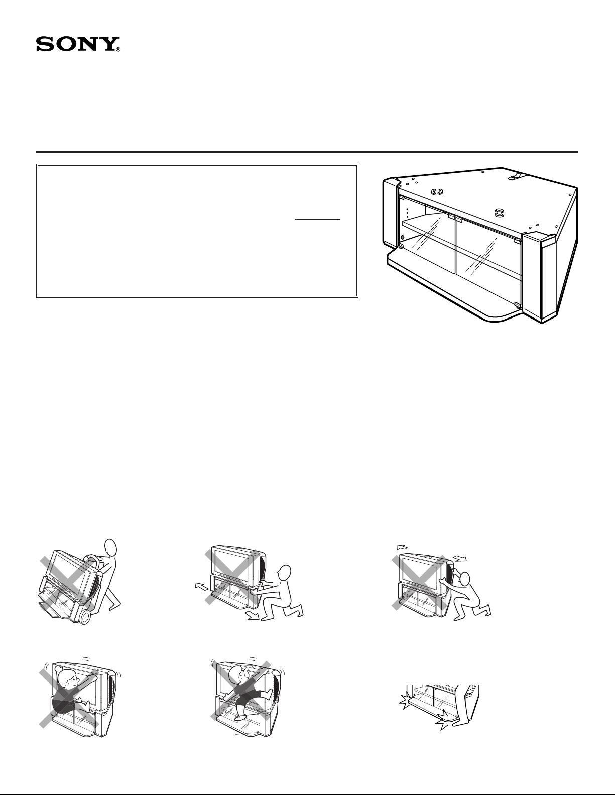
ASSEMBLED STAND
SOPORTE ENSAMBLADO
MEUBLE ASSEMBLÉ
NOTES D’EMPLOI
Ne pas in staller le meu ble à proximi té d’une
source de chaleur, notamment un radiateur, ou dans
un endroit exposé aux rayons directs du soleil.
Nettoyer régulièrement le meuble avec un chiffon
doux. S’il est difficile d’éliminer des empreintes,
de s tac he s de b oisson ou d ’a liment s, par
ex emple, utiliser un chiffon humide et une
solution de détergent doux. Ne pas utiliser de
poudre à récurer, de tampon abrasif ni de solvant.
WARNING / ADVERTENCIA / AVERTISSEMENT
Do not use dolly.
No usar una carretilla.
Ne pas utiliser un diable.
To avoid serious injury, do
not allow children to hang
from the television set.
Para evitar lesiones
graves, no permita que
los niños se cuelguen del
televisor.
Pour éviter les blessures
graves, ne pas laisser les
enfants se suspendre au
téléviseur.
© 2002 by Sony Electronics Inc.
Do not push/pull on legs
of TV stand.
No empujar ni jalar las
patas del soporte de
televisor.
Ne pas pousser ni tirer
sur les pattes du meuble
de télévision.
To avoid injury to the user and
damage to the stand, do not
use the shelf as a step.
Para evitar lesiones al usuario
y daños al soporte, no use la
repisa como escalón.
Pour éviter de se blesser et
d’endommager le meuble,
ne pas l’utiliser comme
marchepied.
1
Do not push/pull TV set.
No empujar ni jalar el
televisor.
Ne pas pousser ni tirer le
téléviseur.
Be cautious of the base
board when walking near
the stand to prevent foot
injury.
Tenga cuidado con la
repisa inferior cuando
camine cerca del soporte
para evitar accidentes.
Lors du passage près
du meuble, il faut faire
attention de ne pas se
blesser les pieds sur le
panneau inférieur.
Page 2
3
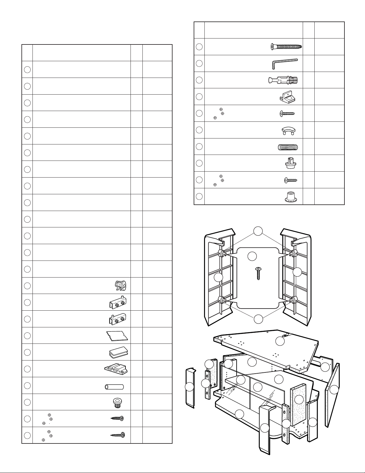
PARTS LIST MODEL : SU-32FS2
LISTA DE PARTES MODELO : SU-32FS2
LISTE DES PIÈCES MODÈLE : SU-32FS2
Item
Description
Artículo
Descripción
Réf.
Description
Top board
Repisa superior
1
Panneau supérieur
Adjustable shelf
Repisa ajustable
2
Etagère réglable
Base board
Repisa inferior
3
Panneau inférieur
Front panel (Right)
Panel frontal (derecho)
4
Panneau avant (droit)
Front panel (Left)
Panel frontal (izquierdo)
5
Panneau avant (gauche)
Inner board (Right)
Soporte interior (derecho)
6
Panneau intérieur (droit)
Inner board (Left)
Soporte interior (izquierdo)
7
Panneau intérieur (gauche)
Front support
Soporte frontal
8
Support avant
Side front
Placa de tope lateral delantera
9
Panneau latéral avant
Side back (Right)
Panel lateral trasero (derecho)
10
Panneau latéral arrière (droit)
Side back (Left)
Panel lateral trasero (izquierdo)
11
Panneau latéral arrière (gauche)
Back panel
Panel trasero
12
Panneau arrière
Glass door
Puerta de vidrio
13
Porte en verre
Cam casting (pre-installed)
Leva moldeada (pre-instalada)
A
Came (pré-installée)
Upper hinge
Bisagra superior
B
Charnière supérieure
Lower hinge
Bisagra inferior
C
Charnière inférieure
Cushion
Almohadilla
D
Coussin
Strike plate
Placa receptora
E
Plaque métallique
Magnet
Imán
F
Aimant
Metal tube
Tubo metálico
G
Tube métallique
Bushing
Buje
H
Coussinet
Screw #6x5/8”
Tornillo #6x5/8”
I
Vis no 6x5/8 po
Screw M3x16
Tornillo M3x16
J
Vis M3x16
Qty
Part No.
Cant.
Nro. de parte
Qté
N° de pièce
1 XW3721
1 XW2943
1 XW2937
1 XP0113
1 XP0132
1 XW2941
1 XW2942
2 XW2945
2 XW2944
1 XW2939
1 XW2940
1 XW2934
2 G0365
12 B0056
2 M0026
2 M0027
2 G0095
2 M0056
1 P0237
4 M0019
4 P0010
8 S0030
2 S0034
Item
Description
Artículo
Descripción
Réf.
Description
Conrmat screw (Hex. Socket head)
Tornillo conrmat (cabeza hueca hexagonal)
K
Vis (hexagonale à tête creuse)
Allen wrench
Llave Allen
L
Clé mâle
Spreading bolt
Esprea
M
Goujon d’accrochage
TV clip holder
Sujetador de plástico
N
Agrafe de retenue du téléviseur
Screw M4x16
Tornillo M4x16
O
Vis M4x16
Stop guide
Guía de tope
P
Butée
Dowel Ø8x30
Espiga Ø8x30
Q
Tourillon Ø8x30
Latch (pre-installed)
Retén (pre-instalado)
R
Taquet (pré-installé)
Screw M3x10 (pre-installed)
Tornillo M3x10 (pre-instalado)
S
Vis M3x10 (pré-installé)
Receptical (pre-installed)
Receptáculo (pre-instalado)
T
Réceptacle (pré-installée)
FRONT PANEL (RIGHT)
PANEL FRONTAL (DERECHO)
PANNEAU AVANT (DROIT)
4
9
8
5
7
13
3
R
S x 4
(pre-installed)
(pre-instalado)
(pré-installé)
R
11
13
4
Qty
Part No.
Cant.
Nro. de parte
Qté
N° de pièce
12 S0035
1 M0018
12 B0077
1 P0178
1 S0122
4 P0088
6 W0092
4 P0279
4 S0150
4 P0280
FRONT PANEL (LEFT)
PANEL FRONTAL (IZQUIERDO)
PANNEAU AVANT (GAUCHE)
5
1
12
2
10
6
8
9
2
Page 3
NOTES ON ASSEMBLY
You will need a medium size Phillips head screwdriver.
Assemble the stand only by the method shown in this
instruction sheet.
Assemble the stand near the location where the stand will be used.
The circled letters in the illustrations are the same as those in the “PARTS LIST”.
For easier assembly, line up the parts in the order they will be required.
Retain this manual for future reference.
NOTAS ACERCA DEL MONTAJE
Usted necesitará un desarmador mediano de cruz.
Ensamble el soporte del televisor siguiendo únicamente el método mostrado en
estas instrucciones.
Arme cerca del lugar donde se usará.
Las letras encerradas en círculo en las ilustraciones son las mismas que en la
“LISTA DE PARTES”. Para facilitar el montaje, alinee las partes en el orden en
que serán usadas.
Conserve este manual para referencia futura.
NOTES D’ASSEMBLAGE
Il faut un tournevis cruciforme de taille moyenne.
Il faut assembler le meuble uniquement selon la méthode décrite dans ce bulletin
d’instruction.
Assembler le meuble près de l’endroit où il doit être utilisé.
Les lettres entourées dans les schémas sont les mêmes que celles gurant dans la
« LISTE DES PIÈCES ». An de faciliter l’assemblage, aligner les pièces dans
l’ordre de montage.
Garder ce manuel pour référence ultérieure.
NOTE: Cam casts are pre-installed into wood pieces.
NOTA: Las levas moldeadas vienen pre-instaladas en las piezas de madera.
NOTE - Les cames sont pré-installées dans les pièces en bois.
REPLACEMENT PARTS INFORMATION
Review the parts list before assembly.
Please examine all packing material before discarding.
If any parts are missing or damaged, identify and refer to
the instructions on the warranty page.
To purchase replacement parts only, call the telephone
number listed below.
1-619-661-6136 for residents of the United States.
1-877-779-9929 for residents of Canada.
INFORMACIÓN SOBRE PARTES DE REEMPLAZO
(Partes para el soporte del televisor únicamente)
Revise la lista de partes antes de ensamblar.
Por favor examine el material del empaque antes de tirarlo.
Si alguna parte falta o está dañada, identifíquela y siga las
instrucciones en la hoja de garantía.
Para ordenar partes de reemplazo, llame al teléfono indicado
a continuación.
1-619-661-6136 para residentes de los Estados Unidos.
1-877-779-9929 para residentes de Canadá.
INFORMATIONS SUR LES PIÈCES DE RECHANGE
Vérier toutes les pièces avant l’assemblage.
Inspecter tous les matériaux d’emballage avant de les jeter.
Si des pièces sont absentes ou défectueuses,
consulter les instructions de la page de garantie.
Pour l’achat de pièces de rechange uniquement, composer le
numéro ci-dessous.
1-619-661-6136 pour les résidents des États-Unis.
1-877-779-9929 pour les résidents du Canada.
(TV stand parts only)
(meuble de télévision uniquement)
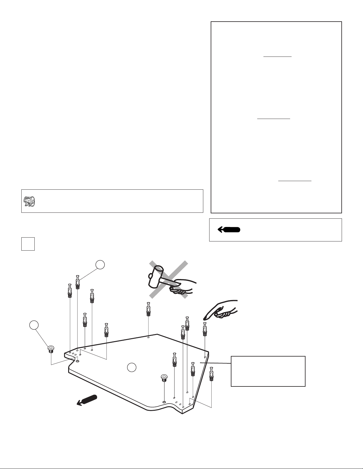
1
H x 2
M x 12
Arrow direction shows front.
La dirección de la echa indica el frente.
La direction de la èche indique l’avant.
INCORRECT
INCORRECTO
INCORRECT
CORRECT
CORRECTO
CORRECT
Insert the spreading bolt by hand into the hole.
Inserte la esprea a mano en el agujero.
Insérer à la main le goujon d’accrochage.
3
BASE BOARD
REPISA INFERIOR
PANNEAU INFÉRIEUR
CAUTION: DO NOT ATTACH THE SPREADING BOLT TO ANY BOARD OR PANEL WITH A HAMMER.
PRECAUCIÓN: NO COLOQUE LA ESPREA EN UNA REPISA O PANEL CON UN MARTILLO.
ATTENTION - NE PAS MONTER AVEC UN MARTEAU LE GOUJON D’ACCROCHAGE SUR UNE PLANCHE OU UN PANNEAU.
Page 4
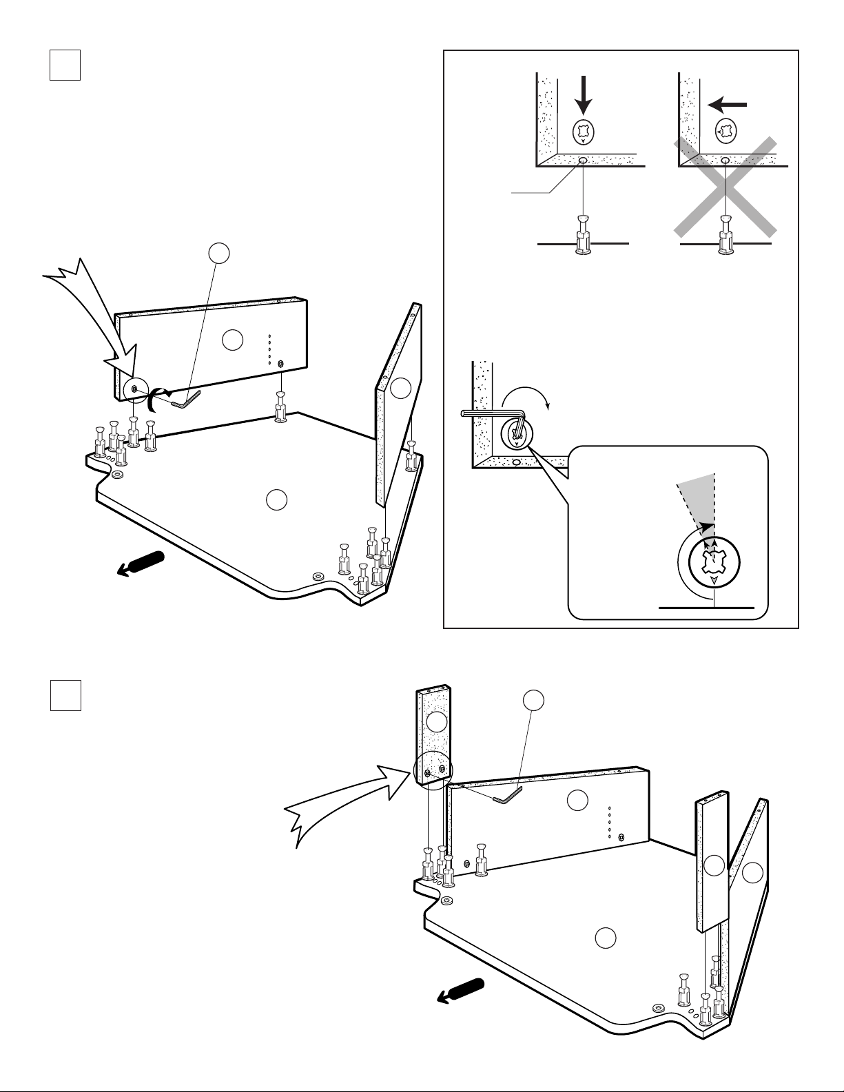
5
2
OK
Fig. 1
See Fig. 1 & 2 on this page.
Ver las ilustraciones 1 y 2 en esta página.
Consulter les Fig. 1 et 2 de cette page.
L
11
3
10
Spreading
bolt hole
Agujero para
la esprea
Orice du goujon
d’accrochage
Fig. 2
NOTE: The arrow mark on the cam casts
must point towards the edge of board.
NOTA: La echa señalada en la “leva moldeada”
debe apuntar hacia el borde de la repisa.
NOTE - La èche sur la came doit être pointée
vers le bord du panneau.
Turn clockwise.
Gire en sentido
horario.
Tourner dans le
sens des aiguilles
d’une montre.
3
See Fig. 1 & 2 on this page.
Ver las ilustraciones 1 y 2 en esta página.
Consulter les Fig. 1 Et 2 de cette page.
L
9
11
9
10
3
4
Page 5

4
7
L
See Fig. 1 & 2 on page 4.
Ver las ilustraciones 1 y 2 en la página 4.
Consulter les Fig. 1 et 2 de la page 4.
5
T x 4
(pre-installed)
(pre-instalado)
(pré-installé)
Q x 4
8
6
9
11
7
11
10
3
9
6
8
3
J x 2
1
F
8
6
10
9
H x 2
UNFINISHED SIDE
LADO SIN ACABADO
CÔTÉ PAS FINI
Page 6

7
7
When attaching top board to side back, side front and
inner board do not tighten the screws. For proper
alignment, hold the panels in place, insert screws in all
the holes, then tighten alternating sides.
Cuando una la repisa superior a las repisas lateral
trasera, lateral delantera e interior, no apriete los tornillos.
Para obtener una alineación apropiada, sostenga los
paneles en posición, inserte los tornillos en todos los
agujeros y luego apriete los tornillos alternando lados.
Ne pas serrer les vis lors de la xation du panneau
supérieur au panneau latéral avant et au panneau
intérieur latéral. Pour obtenir un alignement correct,
maintenir le panneau en place, introduire les vis dans
tous les trous et serrer en alternant les côtés.
8
1
Q x 2
L
K x 12
1
11
7
8
10
3
8
9
9
9
11
7
G x 4
Tighten these 2 screws rst.
Apriete estos 2 tornillos primero.
Serrer d’abord ces 2 vis.
I x 8
2
9
10
6
3
Choose the appropriate holes for shelf adjustment depending on the
components to be installed.
Escoja los agujeros adecuados para ajustar la repisa, dependiendo
de los componentes que se instalarán.
Choisir les trous appropriés pour le réglage de l’étagère en fonction
des éléments à installer.
P x 4
1
10
2
11
9
3
12
6
Page 7

10
TEMPERED GLASS
317.7 mm
(12 1/2")
434 mm
(17 3/32")
Glass door must not extend
past the hinges.
La puerta de vidrio no debe de
sobrepasar las bisagras.
Les charnières doivent être de
E
D
niveau avec le bord de la porte
en verre.
B
E
D
C
DIMENSIONS OF GLASS DOOR
DIMENSIONES DE LA PUERTA DE VIDRIO
DIMENSIONS DE LA PORTE EN VERRE
13
LEFT DOOR
PUERTA IZQUIERDA
PORTE GAUCHE
11
1
Insert the upper side of the glass
door 13 into the upper bushing.
Inserte el lado superior de la
puerta de vidrio 13 en el buje
supérior.
Insérer le haut de la porte en
verre 13 dans le coussinet
supérieur.
2
Insert the hinge C into the hole
of the lower bushing.
Inserte la bisagra C en el
agujero del buje inferior.
Insérer la charnière C dans le
trou du coussinet inférieur.
13
RIGHT DOOR
PUERTA DERECHA
PORTE DROITE
Tempered Glass / Vidrio Templado / Verre Trempé
The glass panels in this stand are made of tempered glass.
Although it is more shock-resistant than ordinary glass, tempered glass may shatter if it receives a sudden shock.
Be careful not to drop or scratch the glass.
Los paneles en este soporte son de vidrio templado.
Aunque es más resistente a los impactos que el vidrio ordinario, puede romperses si recibe un golpe repentino.
Tenga cuidado en no dejar caer ni rayar el vidrio.
Les panneaux en verre de ce meuble sont en verre trempé.
Bien qu’il résiste mieux aux chocs que le verre ordinaire, le verre trempé peut se briser s’il est soumis à un choc brutal.
Il ne faut pas le laisser tomber ni le rayer.
H
1
13
7
C
FOLLOW THE SAME INSTRUCTIONS TO
INSTALL THE RIGHT DOOR.
H
3
SIGA LAS MISMAS INSTRUCCIONES PARA
INSTALAR LA PUERTA DERECHA.
SUIVRE LES MÊMES PROCÉDURES POUR
INSTALLER LA PORTE DROITE.
3
Slide the lower side of glass door 13 into the hinge
and tighten the hinge screws.
Deslice el lado inferior de la puerta de vidrio 13 en
la bisagra y apriete los tornillos de la bisagra.
Glisser le côté inférieur de la porte en verre 13 dans
la charnière et serrer les vis de la charnière.
Page 8

9
DOOR ADJUSTMENT / AJUSTE DE LAS PUERTAS DE VIDRIO / RÉGLAGE DE LA PORTE EN VERRE
Loosen the screws and adjust the glass door positions if the door clearance is not adequate.
Aoje los tornillos y ajuste las posiciones de las puertas si el espacio no es adecuado.
Desserrer les vis et régler la position de la porte en verre si l’écart n’est pas adéquat.
CAUTION: FAILURE TO SECURELY FASTEN THE DOOR WHEN TIGHTENING THE HINGE SCREWS COULD RESULT IN INJURY.
PRECAUCIÓN: SI NO SE SUJETA LA PUERTA MIENTRAS SE APRIETAN LOS TORNILLOS DE LA BISAGRA, PODRÍAN
PRODUCIRSE LESIONES.
ATTENTION - IL EXISTE UN RISQUE DE BLESSURE SI LES VIS DES CHARNIÈRES DE LA PORTE NE SONT PAS SERRÉES
CORRECTEMENT.
CAUTION / PRECAUCIÓN / ATTENTION
PLEASE INSTALL GLASS DOORS AFTER THE STAND IS SET AT THE FINAL LOCATION.
REMOVE GLASS DOORS PRIOR TO MOVING THE STAND.
FAVOR DE INSTALAR LAS PUERTAS DE VIDRIO DESPUÉS DE COLOCAR EL SOPORTE EN SU POSICIÓN FINAL.
QUITE LAS PUERTAS DE VIDRIO ANTES DE MOVER EL GABINETE.
METTRE LES PORTES EN POSITION APRÈS AVOIR INSTALLÉ LE MEUBLE DANS SON EMPLACEMENT DÉFINITIF.
DÉPOSER LES PORTES EN VERRE AVANT DE DÉPLACER LE MEUBLE.
12
INSTALLING THE TV
INSTALACIÓN DEL TELEVISOR
INSTALLATION DU TÉLÉVISEUR
KV-32FS100
KV-32FS200
KV-34FS100
8
Page 9

13
When attaching items 4 & 5 , align the latches with the
receptacles then push evenly until part is locked into place.
Cuando instale los artículos 4 y 5 , alinee los retenes con los
receptáculos, luego empújelos uniformemente hasta que la
parte quede trabada en posición.
Lors du montage des article 4 et 5 , aligner les taquets sur les
réceptacles et les pousser ensuite jusqu’à ce que la pièce soit
bloquée en place.
5
10
CAUTION: TO AVOID SERIOUS INJURY TO YOUR HANDS AND
FINGERS, PLEASE ATTACH THE FRONT PANELS 4 & 5
AFTER PLACING THE TELEVISION ON THE STAND.
PRECAUCIÓN: PARA EVITAR LAS LESIONES GRAVES DE LAS
MANOS Y DEDOS, INSTALE LOS PANELES FRONTALES 4 Y 5
DESPUÉS DE HABER COLOCADO EL TELEVISOR EN EL SOPORTE.
ATTENTION - POUR ÉVITER DES BLESSURES GRAVES DES
MAINS ET DES DOIGTS, MONTER LES PANNEAUX AVANT 4 ET 5
APRÈS AVOIR MIS LE TÉLÉVISEUR SUR LE MEUBLE.
4
14
NOTE: FOLLOWING STEP 14 WILL INCREASE THE STABILITY OF THE FINAL TELEVISION/STAND UNIT.
NOTA: SEGUIR EL PASO 14 INCREMENTARÁ LA ESTABILIDAD DE LA COMBINACIÓN DE TELEVISOR/SOPORTE.
NOTE - L’ÉTAPE 14 CI-DESSOUS AUGMENTE LA STABILITÉ DE L’ENSEMBLE TÉLÉVISEUR ET MEUBLE.
Attach the TV clip holder to the TV with the screw.
1
Then, insert the buckle into the slot on the TV clip
holder.
3
Ajuste el sujetador de plástico al televisor con el
tornillo. Luego, inserte la hebilla en la ranura del
sujetador.
Monter l’agrafe de retenue du téléviseur au téléviseur
à l’aide de la vis. Insérer ensuite la boucle dans la
fente de l’agrafe de retenue du téléviseur.
O
Tighten the strap by
2
pulling in downward
direction.
Apriete la correa jalando
hacia abajo.
Tirer la courroie vers le
bas pour la serrer.
9
N
Page 10

11
894
(35 3/16)
647.2
(25 1/2)
443
(17 7/16)
492
(19 3/8)
507.6
(20)
525.5
(20 11/16)
484.2
(19 1/16)
279.8
(11 1/32)
399
(15 23/32)
628.5
(24 3/4)
626
(24 5/8)
144.3
(5 11/16)
189.8
(7 15/32)
159.8
(6 9/32)
249.8
(9 27/32)
219.8
(8 21/32)
174.3
(6 7/8)
264.3
(10 13/32)
234.3
(9 7/32)
204.3
(8 1/32)
90 kg (198 lbs. 7 oz)
25 kg (55 lbs. 2 oz)
25 kg (55 lbs. 2 oz)
DIMENSIONS
DIMENSIONES
DIMENSIONS
Weight : Approx. 30.8 Kg (68 lbs.)
Peso : Aprox. 30.8 Kg (68 lbs.)
Poids : Approx. 30.8 Kg (68 lbs.)
Unit : mm (inches)
Unidad : mm (pulgadas)
Unité : mm (pouces)
CARRYING CAPACITY OF EACH SHELF
RESISTENCIA DE CADA REPISA
CAPACITÉ DE RÉSISTANCE DES ÉTAGÈRES
SONY ELECTRONICS INC. PRINTED IN USA
SONY ELECTRONICS INC. IMPRESO EN EUA
SONY ELECTRONICS INC. IMPRIMÉ AUX ÉTATS-UNIS
Design and specications subject to change without notice.
Diseño y especicaciones sujetos a cambio sin previo aviso.
Conception et caractéristiques sous réserve de modication sans avis préalable.
10
Page 11

FOR RESIDENTS OF CANADA
POUR LES RÉSIDENTS DU CANADA
PARA RESIDENTES DE CANADÁ
Please examine all packaging materials before discarding.
If any parts are missing or damaged,
please review the parts list found in the assembly manual,
identify the missing or damaged part,
and call the Sony customer service center at
SU-32FS2
1-877-779-9929.
Inspecter tous les matériaux d’emballage avant de les jeter.
Si des pièces sont absentes ou défectueuses,
consulter la liste des pièces du manuel de montage,
identier les pièces absentes ou endommagées
et appeler le service clientèle de Sony au
1-877-779-9929.
Por favor examine todo el material de empaque antes de tirarlo.
Si cualquier parte resulta faltante o está dañada,
por favor revise la lista de partes que se encuentra en el manual de ensamblaje,
identique la parte dañada o faltante
y llame al centro servicio al cliente de Sony al
1-877-779-9929.
Page 12

FOR RESIDENTS OF THE UNITED STATES
S
LIMITED WARRANTY
Sony Electronics Inc. (“Sony”) warrants this product against defects in material or workmanship, subject to
any conditions set forth as follows:
1. This warranty is expressly limited to the replacement of Sony TV Stand parts and components.
2. For a period of 30 days from the date of purchase, Sony will supply parts that are determined to be
defective or missing, at no charge, to the original purchaser. After the warranty period, you will be
charged for all orders.
This warranty does not cover damages which occur in shipment or failures due to acts of God, accident,
misuse, abuse, negligence, faulty installation, misapplication, setup, improper maintenance, commercial use,
or modification of, or to any part of the product. This warranty does not cover Products sold AS IS or WITH
ALL FAULTS. This warranty is valid only in the United States.
Proof of purchase in the form of a bill of sale or receipted invoice, which is evidence that the unit is within the
warranty period, must be presented to obtain the replacement parts.
REPLACEMENT PARTS AS PROVIDED UNDER THIS WARRANTY ARE THE EXCLUSIVE REMEDY OF THE CONSUMER. SONY SHALL NOT BE LIABLE FOR ANY INCIDENTAL OR CONSEQUENTIAL DAMAGES FOR BREACH OF ANY EXPRESS OR IMPLIED WARRANTY ON THIS PRODUCT. EXCEPT TO THE EXTENT PROHIBITED BY APPLICABLE LAW, ANY IMPLIED WARRANTY
OF MERCHANTABILITY OR FITNESS FOR A PARTICULAR PURPOSE ON THIS PRODUCT IS LIMITED IN DURATION TO THE DURATION OF THIS WARRANTY.
Some states do not allow the exclusion or limitation of incidental or consequential damages, or allow limitations on how long an implied warranty lasts, so the above limitations or exclusions may not apply to you. This
warranty gives you specific legal rights, and you may have other rights which vary from state to state.
In order to obtain replacement parts, you must provide a
PROOF OF PURCHASE and complete the informa-
tion on this warranty card. Fax or mail these to:
Tocabi America Corp.
755 Main Street, Chula Vista, CA 91911
Fax No.: (619) 656-8181
www.tocabi.com
Name:
Address:
City: State: Zip Code: Phone:
Model:
Part No. Description Quantity Reason
4-064-678-01 Printed in USA
TV Stand
PARA RESIDENTES DE LOS ESTADOS UNIDOS
POUR LES RÉSIDENTS DES ÉTATS-UNIS
SU-32FS2
12
R0986
 Loading...