

Sony STWA-C101 Operating Instructions Manual
Data Transmitter
4-418-907-04 (1)
STWA-C101
© 2011 Sony Corporation
Operating Instructions
Mode d’emploi
Manual de instrucciones
Bedienungsanleitung
Istruzioni per l’uso
GB
FR
ES
DE
IT

Before operating the unit, please read this
manual thoroughly and retain it for future
reference.
Owner’s Record
The model and serial numbers are located on
the bottom. Record these numbers in the
spaces provided below. Refer to these
numbers whenever you call upon your Sony
dealer regarding this product.
Model No._________________
Serial No._________________
WARNING
To reduce the risk of fire or electric
shock, do not expose this apparatus
to rain or moisture.
To avoid electrical shock, do not open
the cabinet. Refer servicing to
qualified personnel only.
CAUTION
The apparatus shall not be exposed to
dripping or splashing. No objects filled with
liquids, such as vases, shall be placed on the
apparatus.
IMPORTANT
The nameplate is located on the bottom.
For the customers in the U.S.A.
This equipment has been tested and found to
comply with the limits for a Class A digital
device, pursuant to part 15 of the FCC Rules.
These limits are designed to provide
reasonable protection against harmful
interference when the equipment is operated
in a commercial environment. This
equipment generates, uses, and can radiate
radio frequency energy and, if not installed
and used in accordance with the instruction
manual, may cause harmful interference to
radio communications. Operation of this
equipment in a residential area is likely to
cause harmful interference in which case the
user will be required to correct the
interference at his own expense.
You are cautioned that any changes or
modifications not expressly approved in this
manual could void your authority to operate
this equipment.
This device complies with part 15 of the
FCC Rules. Operation is subject to the
following two conditions: (1) This device
may not cause harmful interference, and (2)
this device must accept any interference
received, including interference that may
cause undesired operation.
This transmitter must not be co-located or
operated in conjunction with any other
antenna or transmitter.
This equipment complies with FCC
radiation exposure limits set forth for an
uncontrolled environment and meets the
FCC radio frequency (RF) Exposure
Guidelines in Supplement C to OET65. This
equipment has very low levels of RF energy
that it deemed to comply without maximum
permissive exposure evaluation (MPE). But
it is desirable that it should be installed and
operated keeping the radiator at least 20cm
or more away from person’s body (excluding
extremities: hands, wrists, feet and ankles).
For the customers in Canada
This Class A digital apparatus complies with
Canadian ICES-003.
This device complies with Industry Canada
licence-exempt RSS standard(s). Operation
is subject to the following two conditions:
(1) this device may not cause interference,
and (2) this device must accept any
interference, including interference that may
cause undesired operation of the device.
This equipment complies with IC radiation
exposure limits set forth for an uncontrolled
environment and meets RSS-102 of the IC
radio frequency (RF) Exposure rules. This
equipment has very low levels of RF energy
that it deemed to comply without maximum
permissive exposure evaluation (MPE). But
it is desirable that it should be installed and
operated keeping the radiator at least 20cm
or more away from person’s body (excluding
extremities: hands, wrists, feet and ankles).
GB
2
The term “IC:” before the radio certification
number only signifies that Industry Canada
technical specifications were met.
For the customers in Europe,
Australia and New Zealand
WARNING
This is a Class A product. In a domestic
environment, this product may cause radio
interference in which case the user may be
required to take adequate measures.
For the customers in Europe
This product has been manufactured by or
on behalf of Sony Corporation, 1-7-1 Konan
Minato-ku Tokyo, 108-0075 Jap an. Inquiries
related to product compliance based on
European Union legislation shall be
addressed to the authorized representative,
Sony Deutschland GmbH, Hedelfinger
Strasse 61, 70327 Stuttgart, Germany. For
any service or guarantee matters, please
Hierbij verklaart Sony Corporation dat het toestel STWA-C101/Datazender in
Dutch
English
French
German
Italian
Norwegian
Spanish
overeenstemming is met de essentiële eisen en de andere relevante bepalingen
van richtlijn 1999/5/EG. Nadere informatie kunt u vinden op:
http://www.compliance.sony.de/
Hereby, Sony Corporation, declares that this STWA-C101/Data Transmitter is in
compliance with the essential requirements and other relevant provisions of the
Directive 1999/5/EC. For details, please access the following URL:
http://www.compliance.sony.de/
Par la présente Sony Corporation declare que l’appareil STWA-C101/Emetteur
de données est conforme aux exigencies essentielles et aux autres dispositions
pertinentes de la directive 1999/5/CE. Pour toute information complémentaire,
veuillez consulter l’URL suivante: http://www.compliance.sony.de/
Hiermit erklärt Sony Corporation, dass sich das Gerät STWA-C101/
Datensender in Übereinstimmung mit den grundlegenden Anforderungen und
den übrigen einschlägigen Bestimmungen der Richtlinie 1999/5/EG befindet.
Weitere Informationen erhältlich unter: http://www.compliance.sony.de/
Con la presente Sony Corporation dichiara che questo STWA-C101/
Trasmittente dati è conforme ai requisiti essenziali ed alle alter disposizioni
pertinenti stabilite dalla direttiva 1999/5/CE. Per ulteriori dettagli, si prega di
consultare il seguente URL: http://www.compliance.sony.de/
Sony Corporation erklærer herved at STWA-C101/datasender er i samsvar med
de grunnleggende krav og øvrige relevante krav i direktiv 1999/5/EF. For flere
detaljer, vennligst se: http://www.compliance.sony.de/
Por medio de la presente Sony Corporation declara que el STWA-C101/
transmisor de datos cumple con los requisitos esenciales y cualesquiera otras
disposiciones aplicables o exigibles de la Directiva 1999/5/CE. Para mayor
información, por favor consulte el siguiente URL:
http://www.compliance.sony.de/
refer to the addresses provided in the
separate service or guarantee documents.
This apparatus shall not be used in the
residential area.
GB
GB
3

Tu r k i sh
Sony Corporation, STWA-C101/Veri İleticisi ürünü için gerekli tüm testleri
1999/5/EC Direktifine göre yapmış bulunmaktadır. Daha detaylı bilgi için lütfen
web sayfasını ziyaret ediniz: URL: http://www.compliance.sony.de/
For the customers in Italy
Use of the RLAN network is governed:
- with respect to private use, by the
Legislative Decree of 1.8.2003, no. 259
(“Code of Electronic Communications”).
In particular Article 104 indicates when
the prior obtainment of a general
authorization is required and Art. 105
indicates when free use is permitted;
- with respect to the supply to the public of
the RLAN access to telecom networks and
services, by the Ministerial Decree
28.5.2003, as amended, and Art. 25
(general authorization for electronic
communications networks and services) of
the Code of electronic communications
For the customers in Norway
Use of this radio equipment is not allowed in
the geographical area within a radius of
20 km from the centre of Ny-Ålesund,
Svalbard.
For kundene i Norge
Det er ikke tillatt å bruke dette radioutstyret
innen en radius på 20 km fra sentrum av
Ny-Ålesund, Svalbard.
AVERTISSEMENT
Afin de réduire les risques d’incendie
ou d’électrocution, ne pas exposer
cet appareil à la pluie ou à l’humidité.
Afin d’écarter tout risque
d’électrocution, garder le coffret
fermé. Ne confier l’entretien de
l’appareil qu’à un personnel qualifié.
Pour les clients au Canada
Cet appareil numérique de la classe A est
conforme à la norme NMB-003 du Canada.
Le présent appareil est conforme aux CNR
d’Industrie Canada applicables aux
appareils radio exempts de licence.
L’exploitation est autorisée aux deux
conditions suivantes : (1) l’appareil ne doit
pas produire de brouillage, et (2) l’utilisateur
de l’appareil doit accepter tout brouillage
radioélectrique subi, même si le brouillage
est susceptible d’en compromettre le
fonctionnement.
Cet équipement est conforme aux limites
d’exposition aux rayonnements énoncées
pour un environnement non contrôlé et
respecte les règles d’exposition aux
fréquences radioélectriques (RF) CNR-102
de l’IC. Cet équipement émet une énergie
RF très faible qui est considérée conforme
sans évaluation de l’exposition maximale
autorisée. Cependant, cet équipement doit
être installé et utilisé en gardant une distance
de 20 cm ou plus entre le dispositif
rayonnant et le corps (à l’exception des
extrémités : mains, poignets, pieds et
chevilles).
La mention « IC: » devant le numéro de
certification/ homologation signifie
uniquement que les spécifications
techniques d’Industrie Canada sont
remplies.
Pour les clients en Europe, Australie
et Nouvelle-Zélande
ATTENTION
Eviter d’exposer l’appareil à un égouttement
ou à des éclaboussures. Ne placer aucun
objet rempli de liquide, comme un vase, sur
l’appareil.
IMPORTANT
La plaque signalétique se situe sous
l’appareil.
GB
4
AVERTISSEMENT
Il s’agit d’un produit de Classe A. Dans un
environnement domestique, cet appareil
peut provoquer des interférences radio, dans
ce cas l’utilisateur peut être amené à prendre
des mesures appropriées.

Pour les clients en Europe
Ce produit a été fabriqué par ou pour le
compte de Sony Corporation, 1-7-1 Konan
Minato-ku Tokyo, 108-0075 Japon. Toutes
les questions relatives à la conformité des
produits basées sur la législation européenne
doivent être adressées à son représentant,
Sony Deutschland GmbH, Hedelfinger
Strasse 61, 70327 Stuttgart, Allemagne.
Pour toute question relative au Service
Après-Vente ou à la Garantie, merci de bien
vouloir vous référer aux coordonnées qui
vous sont communiquées dans les
documents « Service (SAV) » ou Garantie.
Ne pas utiliser cet appareil dans une zone
résidentielle.
Pour les clients en Italie
L’utilisation des réseaux RLAN est régie :
- en ce qui concerne l’utilisation à des fins
privées, par le Décret législatif du 1er août
2003, No. 259 (« Code des
communications électroniques »). En
particulier, l’Article 104 qui stipule quand
l’obtention préalable d’une autorisation
générale est requise, et l’Article 105 qui
précise quand une utilisation libre est
permise ;
- en ce qui concerne la fourniture au public
d’un accès RLAN aux réseaux et services
de télécommunications, par le Décret
ministériel du 28 mai 2003, et de l’Article
25 (autorisation générale pour les réseaux
et services de communications
électroniques) du Code des
communications électroniques ;
VORSICHT
Das Gerät ist nicht tropf- und
spritzwassergeschützt. Es dürfen keine mit
Flüssigkeiten gefüllten Gegenstände, z. B.
Vasen, darauf abgestellt werden.
WICHTIG
Das Namensschild befindet sich auf der
Unterseite des Gerätes.
Für Kunden in Europa, Australien und
Neuseeland
WARNUNG
Dies ist eine Einrichtung, welche die FunkEntstörung nach Klasse A besitzt. Diese
Einrichtung kann im Wohnbereich
Funkstörungen verursachen; in diesem Fall
kann vom Betreiber verlangt werden,
angemessene Maßnahmen durchzuführen
und dafür aufzukommen.
Für Kunden in Europa
Dieses Produkt wurde von oder für Sony
Corporation, 1-7-1 Konan Minato-ku Tokio,
108-0075 Japan hergestellt.
Bei Fragen zur Produktkonformität auf
Grundlage der Gesetzgebung der
Europäischen Union kontaktieren Sie bitte
den Bevollmächtigten Sony Deutschland
GmbH, Hedelfinger Strasse 61, 70327
Stuttgart, Deutschland. Für Kundendienst
oder Garantieangelegenheiten wenden Sie
sich bitte an die in den Kundendienst- oder
Garantiedokumenten genannten Adressen.
Dieser Apparat darf nicht im Wohnbereich
verwendet werden.
WARNUNG
Um die Gefahr von Bränden oder
elektrischen Schlägen zu verringern,
darf dieses Gerät nicht Regen oder
Feuchtigkeit ausgesetzt werden.
Um einen elektrischen Schlag zu
vermeiden, darf das Gehäuse nicht
geöffnet werden. Überlassen Sie
Wartungsarbeiten stets nur
qualifiziertem Fachpersonal.
Für Kunden in Italien
Die Verwendung des RLAN-Netzwerkes
wird geregelt:
- in Bezug auf die private Verwendung
durch die gesetzliche Bestimmung vom
01.08.2003, Nr. 259 („Richtlinie über
elektronische Kommunikation“). Im
Einzelnen gibt Artikel 104 an, wann die
vorherige Einholung einer allgemeinen
Genehmigung erforderlich ist und Art.
105, wann die freie Verwendung erlaubt
ist.
- in Bezug auf die Bereitstellung des
RLAN-Zugangs zu Telekomnetzwerken –
GB
5

und Dienstleistungen für die
Öffentlichkeit, durch die geänderte
amtliche Richtlinie vom 28.05.2003 und
Art. 25 (allgemeine Genehmigung für
elektronische Kommunikationsnetzwerke
und -dienstleistungen) der Richtlinie über
elektronische Kommunikation
Per i clienti in Italia
L’utilizzo della rete RLAN è regolato:
- relativamente all’uso privato, dal Decreto
Legislativo del 1.8.2003, n. 259 (“Codice
delle comunicazioni elettroniche”). In
particolare, l’Articolo 104 indica i casi in
cui è necessario ottenere preventivamente
un’autorizzazione generale, mentre
l’Articolo 105 specifica i casi in cui è
consentito il libero uso;
- relativamente alla fornitura al pubblico
dell’accesso RLAN ai servizi e alle reti di
telecomunicazione, dal Decreto
Ministeriale del 28.5.2003 e successive
modifiche, e dall’Art. 25 (autorizzazione
generale per i servizi e le reti delle
comunicazioni elettroniche) del Codice
delle comunicazioni elettroniche
Para los clientes de Italia
El uso de la red RLAN se rige:
- con respecto al uso privado, por el Decreto
legislativo de 1.8.2003, núm. 259
(“Código de comunicaciones
electrónicas”). En concreto, el artículo 104
indica cuándo se requiere la obtención
previa de una autorización general y el
artículo 105 indica cuándo se permite el
uso libre;
- con respecto al suministro al público del
acceso RLAN a las redes y servicios de
telecomunicaciones, por el Decreto
ministerial de 28.5.2003, según fue
enmendado, y el artículo 25 (autorización
general para redes y servicios de
comunicación electrónica) del Código de
comunicaciones electrónicas
GB
6

Table of Contents
Overview .............................................. 8
System Configuration (Example) .... 8
Precautions ......................................9
Location and Function of
Controls ....................................... 10
Connection .........................................12
Necessary Tools and Items ............ 12
Devices Connection .......................12
Settings ............................................... 12
Computer System Requirement ....12
Setting Screen ................................12
Wireless Channel and Audio Input
Settings ........................................13
Network Settings ...........................14
Closed Caption Language
Settings ........................................14
Software Update ............................14
Suitable Installation Place ................ 15
Wireless Setting Procedure ............... 17
Term .............................................. 17
Pre-Check ......................................17
Channel Allocation ........................ 17
Detecting Crosstalk and
Interference .................................19
Avoiding Crosstalk and
Interference .................................19
Channel Allocation Examples ....... 23
Workaround Examples .................. 28
Specifications ..................................... 31
License ................................................32
GB
7
Overview
System Configuration (Example)
Closed caption data is transmitted from a D-Cinema (digital cinema) server to the unit (Data
Transmitter) through an Ethernet network. Audio data is transported from the D-Cinema server
to the unit via an AES/EBU interface (digital) or phono cable (analog). The unit distributes the
caption data and audio data to receiver boxes over a wireless network.
Captioning glasses*
Digital cinema projector
Movie contents
*
Receiver box
Captions and audio
(wireless network)
Headphones*
* The receiver box outputs to only one device at a time; either the captioning glasses or the headphones.
D-Cinema server
Caption
SMPTE
RJ-45
Data Transmitter
(this unit)
Digital Audio
AES/EBU
RJ-45
Analog Audio
Phono cable
GB
8

Precautions
Notes on temperature and humidity
Store or use the unit within the appropriate
temperature ranges. For details on the
operating and storage conditions, see
“Specifications” (page 31).
Notes on wireless communication
The unit uses the 2.4 GHz band, the same
band at which various devices operate.
Although the unit utilizes technologies to
prevent interference from other devices
using the same band, it may suffer a decrease
in speed or interruption caused by
interference from other devices.
See page 31 for wireless communication
specifications.
Notes on placement
Keep the antennas of the unit away from
metal objects, such as plates, desks or racks.
Otherwise the performance of the antennas
may be impaired.
See page 15 for more details on placement.
Notes on cleaning
Wipe the surface of the unit with a soft dry
cloth. If the unit is badly stained, use a cloth
moistened with neutral detergent to wipe it
clean, and then wipe with a dry cloth.
Do not expose the unit to alcohol, benzine,
thinner, or insecticide. It may impair the
finish of the surface or erase the printed
markers.
Do not scrub the unit hard with a cloth that
contains dust or sand. It may damage the
surface.
GB
9

Location and Function of Controls
Front/Side panel
a Reset button
Press and hold the button for about five
seconds with a thin, straight object (such
as an opened paper clip) to restore the
unit to the factory default settings,
including the IP address.
b (LAN) connector
Connect to the LAN connector (RJ-45)
on the hub or router of your network,
using a LAN cable (category 5 straight
type) (not supplied).
c Digital audio connector
Format: AES/EBU
Connector type: RJ-45
Cable type: LAN cable (category 5
straight type, shielded) (not supplied)
Pin
Function Pin
No.
1NC 2NC
3NC 4NC
5NC 6NC
7 AES/EBU (+) 8 AES/EBU (–)
Function
No.
CAUTION
• For safety, do not connect the connector
for peripheral device wiring that might
have excessive voltage to the following
ports.
: LAN connector
: Digital audio connector
Follow the instructions for the above ports.
• When you connect the digital audio cable
of the unit to peripheral device, use a
shielded-type cable to prevent malfunction
due to radiation noise.
ATT ENT ION
• Par mesure de sécurité, ne raccordez pas le
connecteur pour le câblage de
périphériques pouvant avoir une tension
excessive aux ports suivants.
: Connecteur LAN
: Connecteur audio numérique
Suivez les instructions pour les ports cidessus.
• Lors de la connexion du câble audio
numérique de l'appareil au périphérique,
utilisez un câble blindé afin d'empêcher
tout dysfonctionnement dû au bruit de
rayonnement.
GB
10
VORSICHT
• Aus Sicherheitsgründen nicht mit einem
Peripheriegerät-Anschluss verbinden, der
zu starke Spannung für diese Buchse
haben könnte.
: Buchse LAN
: Digitale Audiobuchse
Folgen Sie den Anweisungen für die oben
aufgeführten Buchsen.
• Verwenden Sie beim Anschließen des
Digital-Audio-Kabels des Geräts an ein
Peripheriegerät ein abgeschirmtes Kabel,
um Fehlfunktionen aufgrund von
Störungen zu vermeiden.
d Analog audio connector
Connector type: phono output jacks
Cable type: stereo phono cable (not
supplied)
Rear panel
e DC IN 5V connector
Connect an AC adaptor (5 V DC, 1 A)
(not supplied).
f Cable holder
Secure the AC adaptor cable with this
holder.
g POWER indicator
Indicates the power status of the unit.
h Screw holes
Secure the unit with four 1/4-inch or M6
screws (recommended, not supplied).
a Antennas
Transmit caption and audio data to
receiver boxes over the wireless
network.
11
GB
Connection
Settings
Necessary Tools and Items
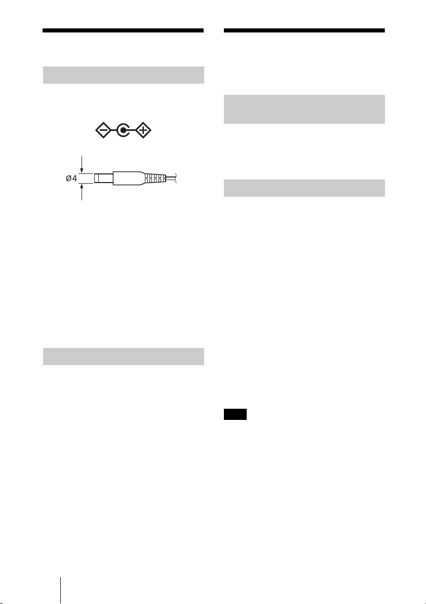
• AC adaptor (output voltage +5 V±5% DC,
output current 1 A or more)
Polarity
Plug dimensions
Outside diameter: 4.0 mm (3/16 inches)
Inside diameter: 1.7 mm (
• Four screws (
recommended; use ones appropriate to
your mounting plate) and a screwdriver
• Two LAN cables (category 5 straight type,
RJ-45) (Use a shielded-type cable for
AES/EBU digital audio connection.)
(When AES/EBU digital audio is not used,
only one LAN cable is necessary.)
• Stereo phono cable (The phono cable is
necessary only when analog audio is
used.)
1
/4-inch or M6
3
/32 inches)
Devices Connection
Be sure to disconnect the AC adaptor from
the unit before connecting other cables.
After connecting other cables, plug the AC
adaptor cable into the DC IN connector of
the unit. Check that the POWER indicator
comes on.
You can use the web browser of a computer
to configure the unit.
Computer System
Requirement
• Operating system
Windows 7
• Recommended web browser
Internet Explorer 8
Setting Screen
Follow the instructions below to open the
setting screen.
1 Start the web browser.
2 Enter the text below into the address
line of the browser.
http://xxx.xxx.xxx.xxx/
xxx.xxx.xxx.xxx: IP address for the unit
The default IP address for the unit is
192.168.10.100.
3 Enter the user name and password and
click “OK” to open the setting screen
of the unit.
User name: admin
Contact your Sony representative for the
password.
Note
You can use the reset button to restore the unit
to the factory default settings, including the IP
address. Press and hold the button for about
five seconds with a thin, straight object (such as
an opened paper clip).
GB
12
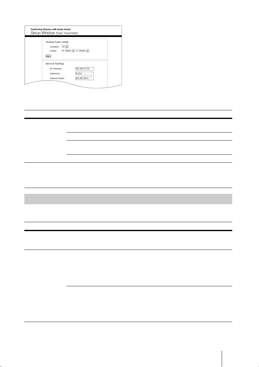
Setting screen
The setting screen shows the following items.
Setting item Function
Settings Channel Audio Config Wireless channel and audio input settings (see
Network Settings IP address settings (see page 14)
Closed Caption Language
Settings
Software Update Software update (see page 14)
Footer Version information Shows the unit information.
page 13)
Closed caption language settings (see page 14)
HW Version.: Hardware version
SW Version.: Software version
Bootloader Ver.: Bootloader version
Wireless Channel and Audio Input Settings
In the “Channel Audio Config” menu, you can set the following settings. After selecting the
settings, click the “Apply” button to save the changes you made.
Setting item Function
Channel Selects the wireless channel over which the closed caption and audio data are
Audio HI
transmitted.
Options are “G1” to “G7” and “Y1” to “Y7.” The default setting is “G1.”
(Hearing Impaired)
VI
(Visually Impaired)
Selects the audio input signal for the hearing impaired.
The default setting is “Digital.”
Digital: Inputs digital audio signal via the AUDIO
(AES/EBU) connector.
Analog: Inputs analog audio signal via the AUDIO
(ANALOG) H jack.
Selects the audio input signal for the visually impaired.
The default setting is “Digital.”
Digital: Inputs digital audio signal via the AUDIO
(AES/EBU) connector.
Analog: Inputs analog audio signal via the AUDIO
(ANALOG) V jack.
13
GB

Network Settings
In the “Network Settings” menu, you can set the following settings. After selecting the settings,
click the “Apply and Restart system” button to save the changes you made and restart the unit.
It takes about one minute for the unit to restart.
Setting item Function
IP Address Sets the IP address of the unit. The default setting is “192.168.10.100.”
Gateway Sets the default gateway IP address.
Subnet Mask Sets the subnet mask of the network. The default setting is “255.255.255.0.”
DCS IP Address Sets the D-Cinema server IP address. The default setting is “192.168.10.101.”
Closed Caption Language
Settings
In the “Closed Caption Language Settings”
menu, you can select up to six languages
from which the users of the captioning
glasses can choose to display the closed
captions. After selecting the language(s),
click the “Apply and Restart system” button
to save the changes you made and restart the
unit. It takes about one minute for the unit to
restart.
Note
If the DCP (Digital Cinema Package) does not
contain closed caption data for the selected
language(s), then no caption data for the
language(s) is transmitted.
Tip
You can select “any Auto-select” in the
language selection. In this case, the default
language is automatically displayed from the
DCP’s closed captions.
Standby Message
You can enter a message that is transmitted
to the receiver when the D-Cinema server is
not playing the DCP that contains closed
captions. You can enter from 2 to 20
characters for the message and can use only
characters supported by the receiver.
RF Power
For service use only. Do not change the
setting.
Test Mode
For service use only. Do not change the
setting.
Software Update
You can update the software of the unit by
following the instructions below.
1 Store the update file in your computer.
You can download the file from the
Digital Cinema web site. Contact your
Sony sales representative for the URL of
the web site.
2 Open the setting screen of the unit.
3 Click “Update” in the “Software
Update” box at the bottom of the
screen.
4 Click “Browse…” to open the file
selection dialog box.
5 Choose the file downloaded in step 1
and click “OK.”
6 Click “Submit and Restart system” to
update the software.
It takes about 30 minutes to complete the
update.
To prevent possible unit malfunctions
Never turn off the unit during the update
process. It may cause a malfunction.
GB
14
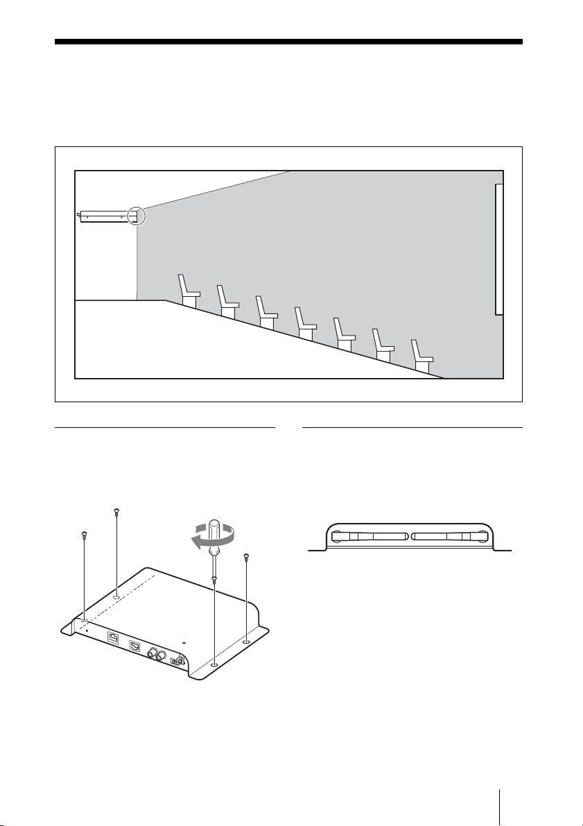
Suitable Installation Place
Locate the unit where the whole auditorium can be viewed unobstructed, such as the inner wall
of the auditorium that separates the auditorium from the projection booth. Put the unit in a
horizontal position with the antennas pointing toward the cinema screen. The transmission
range of the radio waves is about 40 m (131 feet, line-of-sight distance).
Data
Transmitter
Antennas
To fix the unit
Secure the unit to a stable place with four
screws (1/4-inch or M6 recommended; use
ones appropriate to your mounting plate)
(not supplied).
Auditorium
Screen
Notice on antenna position
Check that the antennas are set as illustrated
below. Make sure that they do not contact
other objects. Otherwise, the signal from the
antennas may become weak.
Keep the antennas of the unit away from
metal objects, such as plates, desks or racks.
Do not install the unit upside down.
Also, do not let any metal objects obstruct
the radio path. Otherwise the performance of
the antennas may be impaired.
15
GB
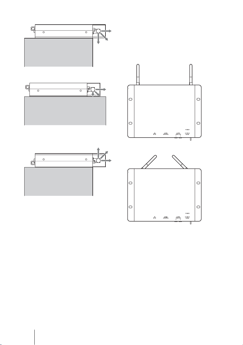
OK
Not OK
Not OK
The unit is installed upside down.
Do not position the antennas as illustrated
below.
Otherwise the signal from the antennas to
the auditorium may become weak, and it
may cause cross-talk with receivers served
in other auditoriums.
Not OK
Not OK
GB
16

Wireless Setting
Procedure
This chapter describes the wireless setting
procedure. In particular, the decision process
for wireless channel allocation and the
wireless communication trouble shooting
process are described, including:
- Wireless channel allocation with multiple
screens
- Trouble shooting, such as sound and
caption interruption.
As a number of transmitters are allocated for
various screen areas in one theater, one
transmitter may affect another screen’s
wireless communication area.
This wireless system uses the 2.4GHz
frequency, and it is possible that other
2.4GHz wireless signal sources, e.g., Wi-Fi
may cause interference in this system.
This chapter describes the wireless channel
allocation procedure, and workarounds for
smooth installation.
This chapter is intended for a theater
operator and Sony service engineer.
Check regularly to make sure that
unnecessary systems are not working.
The STWA-C101/STW-C140GI system
uses the 2.4 GHz frequency. Other devices
that use the same frequency may cause
interference in this system.
Channel Allocation
Allocate the channel for each screen based
on the following fundamental allocation
rule. Otherwise, wireless communication
may not work as a result of crosstalk or other
interference.
There are 14 channels: G1 to G7 (G group)
and Y1 to Y7 (Y group). G group and Y
group communicate independently, even if
they share the same channel number. For
example, although G1 and Y1 share the
same frequency, these channels can be
separated from each other.
Term
Crosstalk: Phenomena resulting in another
transmitter’s signal reaching a different
screen area.
Interference: Infringement of signal from
another wireless signal source of the same
frequency.
Channels: 14 channels that user can choose
G1 - G7 and Y1 - Y7.
Channel number: The numeric attached to
the Channel indicates wireless frequency.
For example, G1 and Y1 use the same
frequency.
Channel-pair: Channels that use the same
channel number. For example, G1 and Y1
are channel-pair.
Pre-Check
- Check all 2.4GHz wireless systems in the
theater.
- Stop them if they are not used.
17
GB
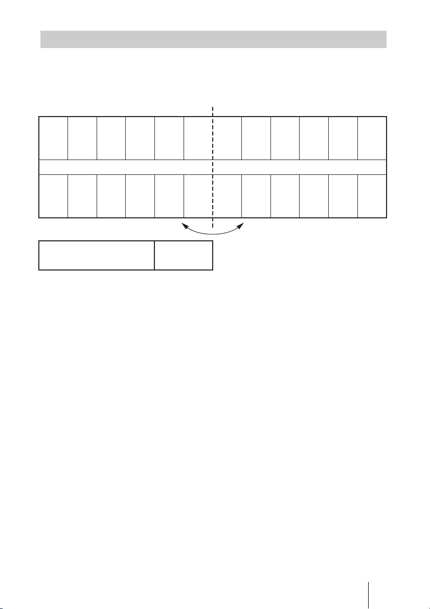
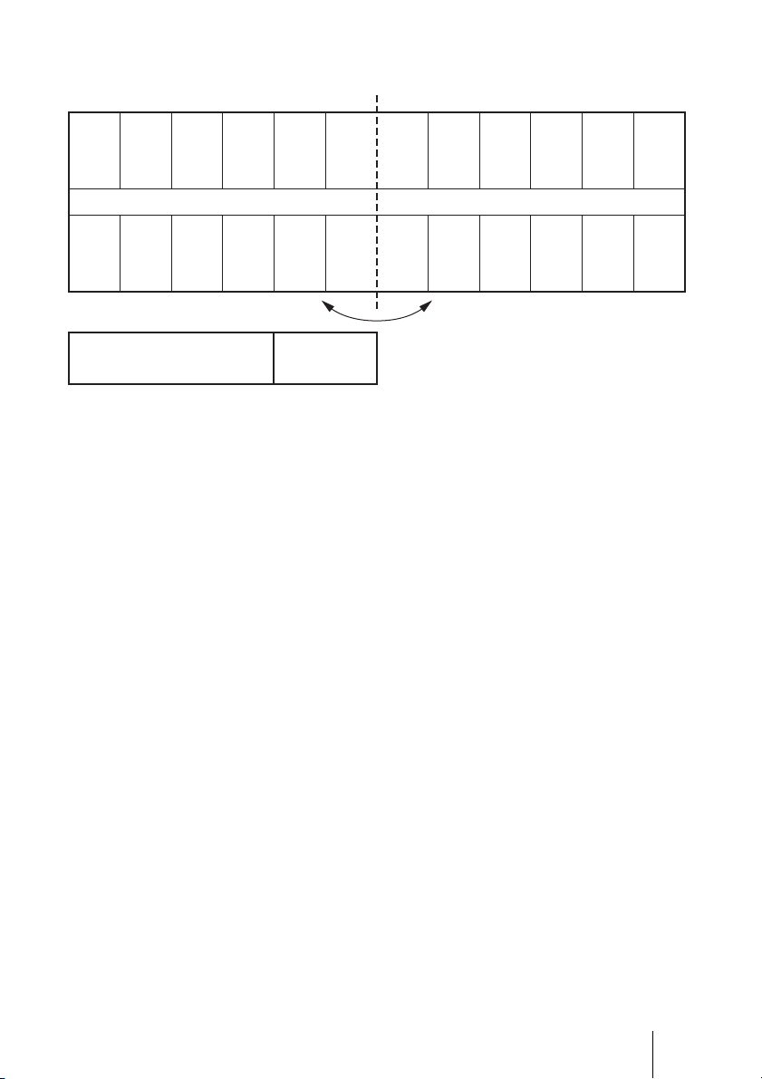
Fundamental allocation rule
1. Choose at least one unallocated channel-pair.
2. If possible, refrain from using the same channel, such as G1 and G1.
3. The same channel number, such as G1 and G1, or G1 and Y1, should not be used for
adjacent screens (side-by-side, facing one another, or diagonally from one another).
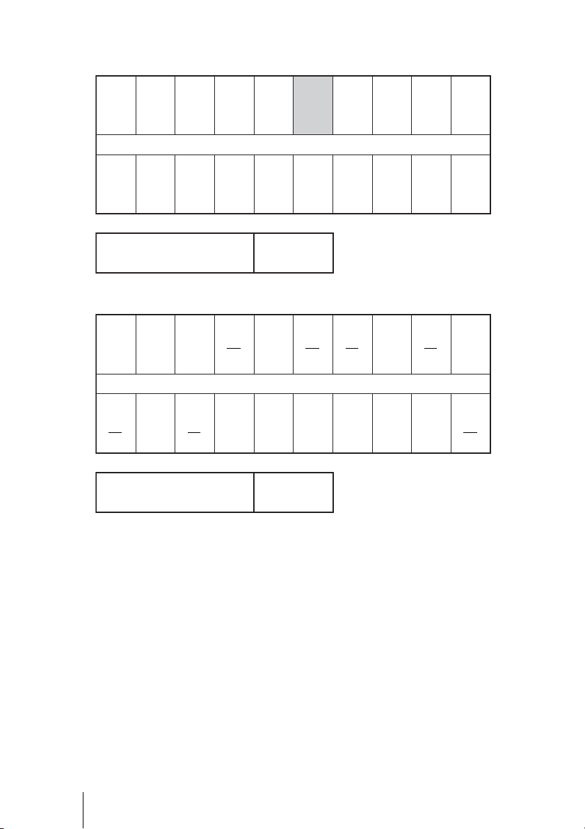
The illustration below shows an example of channel allocation for a theater with 8 screens (1
row of screens on either side of a central corridor). Screens are depicted as rectangular boxes
in the figure. Screens marked "×" break fundamental allocation rule 3.
××
G1 G2 Y2 Y3
Y2 Y2 Y4 Y5
××
The illustration below shows an example of correct channel allocation for a theater with 7
screens on either side of a central corridor.
G1 G2 G3 G4 G5 G7 Y4
Y4 Y5 Y7 Y1 Y2 Y3 G1
Unallocated channels
G6
Y6
- G1 and Y4 are used at 2 screens. Same channels (G1 and G1, Y4 and Y4) should be allocated
as far from one another as possible, as shown in the illustration.
- Channel groups of the same number (e.g. G1 and Y1) can be allocated to screens closer
together than identical channels (G1 and G1).
- Channel-pair G6 and Y6 is kept unallocated in the example. The unallocated channel-pair can
help to avoid crosstalk and interference, as explained in “Avoiding Crosstalk and
Interference” (page 19).
For further examples, see “Channel Allocation Examples” (page 23)
GB
18
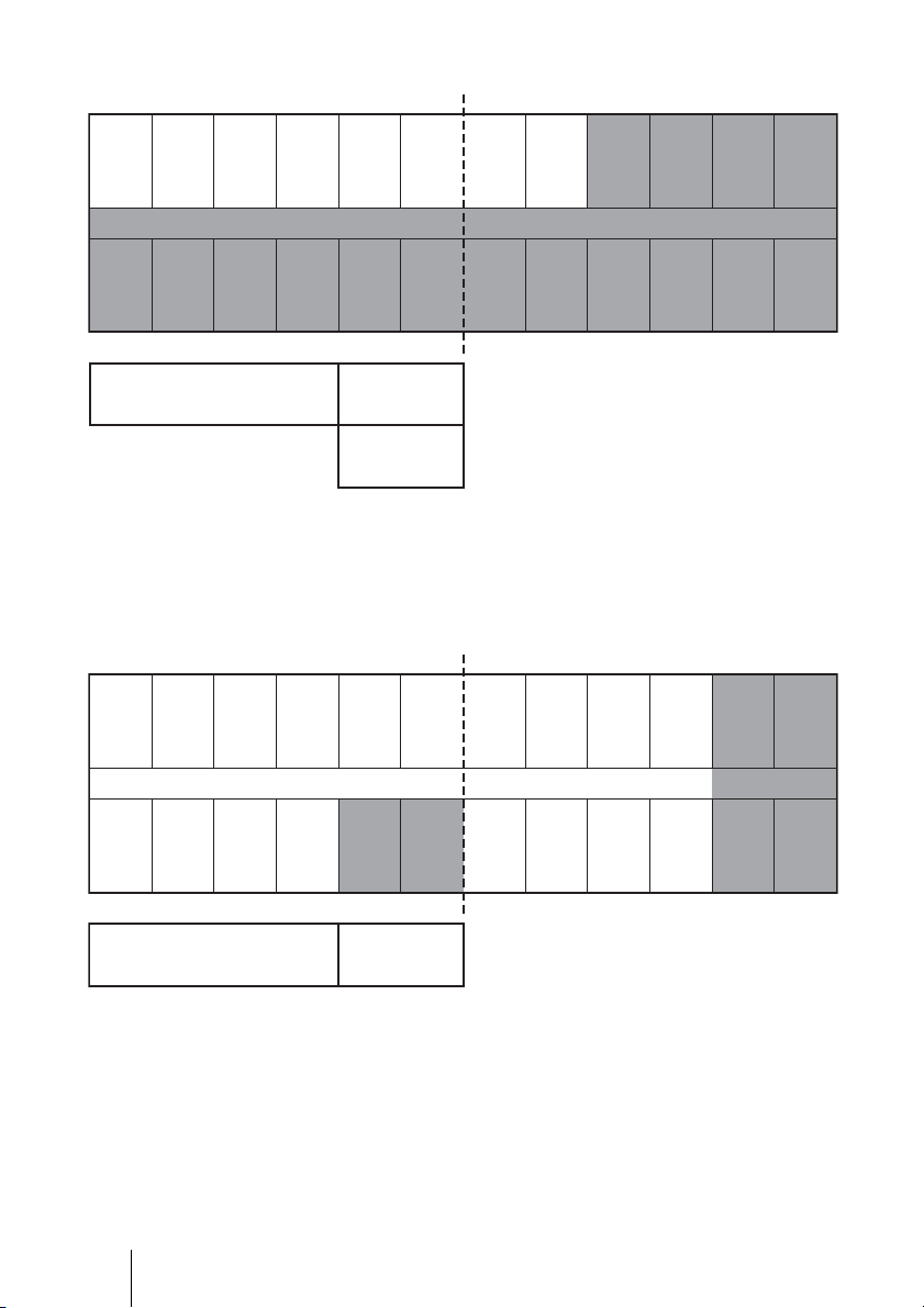
Detecting Crosstalk and Interference
After allocating channels, make sure that the transmitters at all the screens are running and that
no crosstalk or interference occurs at any of the screens.
While you are checking the system, you may recognize problems such as crosstalk or
interference.
Correct transmission can more easily be determined by sound than by captions.
Evaluate HI/VI sound at the center of the auditorium as shown in the illustration below. The
characteristics of the wireless antenna can make data reception in the corner areas of an
auditorium difficult. Also, keep obstacles (including your hand) away from the receiver.
Auditorium
If HI/VI sound breakup occurs frequently, it is likely a result of one or both of the following:
1) Channel allocation does not satisfy the fundamental allocation, resulting in crosstalk.
Check channel allocation again.
2) Another wireless system is causing interference.
A wireless system using the 2.4GHz frequency may be causing interference.
Avoiding Crosstalk and Interference
This section explains how to avoid crosstalk or interference without the need for specialized
equipment. The same approach can be applied in the case of a caption problem. If you cannot
solve the problem, it is likely that specialized equipment is required to resolve it. In this case,
contact a service office.
The illustration below shows a case where sound breakup occurs at Y4 (shown in gray).
G1 G2 G3 G4 G5 G7 Y4
Y4 Y5 Y7 Y1 Y2 Y3 G1
Unallocated channels
G6
Y6
19
GB
The 3-step workaround process is as follows;
Step 1 Re-check Channel Allocation
Make sure that the channel allocation in the theater follows the fundamental allocation rules
(page 18). Also, see “Channel Allocation Examples” (page 23).
After channel allocation, make sure that the transmitters for all the screens are running and no
crosstalk or interference occurs at any of the screens. If the problem is not solved, another
wireless device may be causing the problem. In this case, try Step 2 or Step 3.
Step 2 Use Workaround 1: Replace With Unallocated Channel
1. Check for available unallocated channel-pairs.
In the illustration below, G6 and Y6 are an unallocated channel-pair.
G1 G2 G3 G4 G5 G7 Y4
Y4 Y5 Y7 Y1 Y2 Y3 G1
GB
20
Unallocated channels
G6
Y6#Y#Y

2. Replace the channel at the problem screen with an unallocated channel.
Select a channel of the same channel group. In this case, replace Y4 with Y6.
This action does not break fundamental allocation rule 3.
Y4
After Workaround 1
G1 G2 G3 G4 G5 G7 Y6
Y4 Y5 Y7 Y1 Y2 Y3 G1
Unallocated channels
G6
Y6
3. You may replace the channel for at the problem screen with the other
unallocated channel.
However, replacing with “the other unallocated channel” may break the fundamental allocation
rule 3. Make sure that allocation follows the fundamental allocation rule 3 to avoid possible
crosstalk.
4. With the entire system running, check neither sound nor caption interruption
occurs at the screens where you replaced the channel.
The workaround is success, if there is no problem.
Detailed examples of workaround 1 can be seen in “Workaround Examples” (page 28).
21
GB
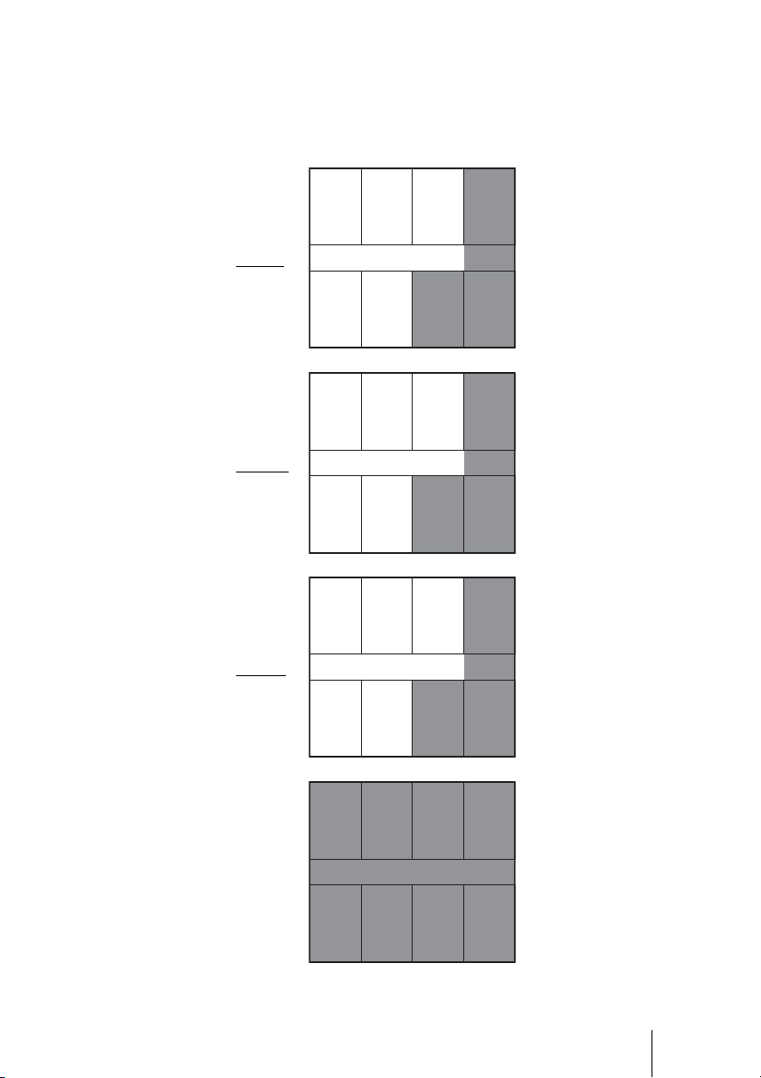
Step 3 Use Workaround 2: Replace Y7 or G7
#Y#G#G
G1 G2 G3 G4 G5 G7 Y4
Y4 Y5 Y7 Y1 Y2 Y3 G1
#Y #Y
1. Replace Y4 and Y7
G7 and Y7 are relatively tolerant about other wireless signals, compared with other
channels.
2. Replace G4 and G7
This action follows fundamental allocation rule 3.
After Workaround 2
G7
G1 G2 G3 G5
Y5 Y1 Y2 Y3 G1
Y7 Y4
G4 Y7
3. Check neither sound nor caption interruption occurs at the screens where you
replaced the Channel with all of the system running.
The workaround is success if there is no problem.
Detailed examples of Workaround 2 can be seen in “Workaround Examples” (page 28).
In Case the Problem is Not Solved
If you cannot solve the problem by the process described above, call the service office.
GB
22
Channel Allocation Examples
This section provides typical examples of channel allocation.
1. Standard channel allocation
The following shows the standard allocation pattern, based on a dual-row theater of 24 screens.
G1 G3 G5 G7 G2 G4 Y7 Y2 Y4 Y1 Y3 Y5
Y7 Y2 Y4 Y1 Y3 Y5 G1 G3 G5 G7 G2 G4
Unallocated channels
G6
Y6
Rows are equally allocated, then the halves
of one row are flipped.
• Cut out a portion of the standard allocation pattern according to each theater layout and
allocate them.
• This standard allocation pattern follows (complies with) the fundamental allocation rule
described in “Channel Allocation” (page 17).
• Description of allocation:
- The available channels are G1-G7 and Y1-Y7. Reserve G6 and Y6 as unallocated channels.
- In order to avoid the cross talk, G row and Y row are flipped at the middle.
- In the case of over 24 screens, repeats the standard allocation pattern as it is.
23
GB
2. In the case of 8 screens in line
G1 G3 G5 G7 G2 G4 Y7 Y2 Y4 Y1 Y3 Y5
Y7 Y2 Y4 Y1 Y3 Y5 G1 G3 G5 G7 G2 G4
Unallocated channels
Y1
Y4
G6
Y6
Y3
Y5
• Cut the portion from G1 to Y2.
• Optionally you can cut the portion from Y7 to G3.
3. In the case of 18 screens in a dual row, with the entrance at the center of the
theater
G1 G3 G5 G7 G2 G4 Y7 Y2 Y4 Y1 Y3 Y5
Y7 Y2 Y4 Y1 Y3 Y5 G1 G3 G5 G7 G2 G4
Entrance
Unallocated channels
Y3
Y5
G6
Y6
• Mask the unnecessary screens as above.
Y3 and Y5 will not be used because there is the entrance.
GB
24
4. Alternative channel allocation pattern
• This pattern is a variation on the standard channel allocation described above.
G1 G2 G3 G4 G5 G7 Y4 Y5 Y7 Y1 Y2 Y3
Y4 Y5 Y7 Y1 Y2 Y3 G1 G2 G3 G4 G5 G7
Unallocated channels
G6
Y6
Rows are equally allocated, then
the halves of one row are flipped.
25
GB

5. Standard channel allocation for stacked screens
The standard channel allocation sample for stacked screens is based on 8 screens per floor. The
sample consists of 4 blocks.
• On the 1st floor, set block 1.
• On the 2nd floor, set block 2.
• On the 3rd floor, set block 3.
• On the 4th floor, set block 4.
Channel allocation example for 8 stacked screens
Block 1
G1 G3 G5 G7
1st floor
Y7 Y2 Y4 Y1
Block 2
G2 G4 Y7 Y2
2nd floor
Y3 Y5 G1 G3
GB
Block 3
Y4 Y1 Y3 Y5
3rd floor
G5 G7 G2 G4
Block 4
G1 G3 G5 G7
4th floor
Y7 Y2 Y4 Y1
26
6. In the case of a 3-floor theater with 5 screens per floor
Cut out the portion of the standard channel allocation pattern for 8 screens stacked, according
to each theater layout and allocate accordingly.
Channel allocation example for a 3-floor theater with 5 screens per floor
Block 1
G1 G3 G5 G7
1st floor
Y7 Y2 Y4 Y1
Block 2
G2 G4 Y7 Y2
2nd floor
Y3 Y5 G1 G3
Block 3
3rd floor
Block 4
Y4 Y1 Y3 Y5
G5 G7 G2 G4
G1 G3 G5 G7
Y7 Y2 Y4 Y1
27
GB
Workaround Examples
Samples of workaround 1: (1)(2)
Samples of workaround 2: (3)
(1)
After allocation Interference
G1 G3 G5 G7 G2 G4 Y7 Y2
#Y
Unallocated channels
Y1 Y3 Y4 Y5
After remediation
G1 G3 G5 G7 G2 G4 Y7
Unallocated channels
Y1 Y3 Y4 Y5
G6
Y6
#Y
Y6
G6
Y2
GB
28

(2)
After allocation
Unallocated channels
After remediation
G1 G3 G5 G7 Y7 Y2 Y4 Y1
Y7 Y2 Y4 Y1 Y3 Y5 G1 G3 G5 G7
Interference
G2#YG4
G1 G3 G5 G7 Y7 Y2 Y4 Y1
Y7 Y2 Y4 Y3 Y5 G1 G3 G5 G7
Y6
G6
Y6
Check channel: Y1
Unallocated channels
G2 G4
G6
29
GB
(3)
After allocation
#G #G #Y #Y
G1 G3 G5 G7 G2 G4 Y7 Y2 Y4 Y1
Y7 Y2 Y4 Y1 Y3 Y5 G1 G3 G5 G7
#Y #Y #G
Interference
Unallocated channels
After remediation
G4
G1 G3 G5 G2 Y2 Y1
Y2 Y1 Y3 Y5 G1 G3 G5
Y4 Y7 G4
Unallocated channels
G6
Y6
G7 Y4 Y7
G6
Y6
Check channel: G4, G7, Y4, Y7
GB
30
 Loading...