

STR-W770
SERVICE MANUAL
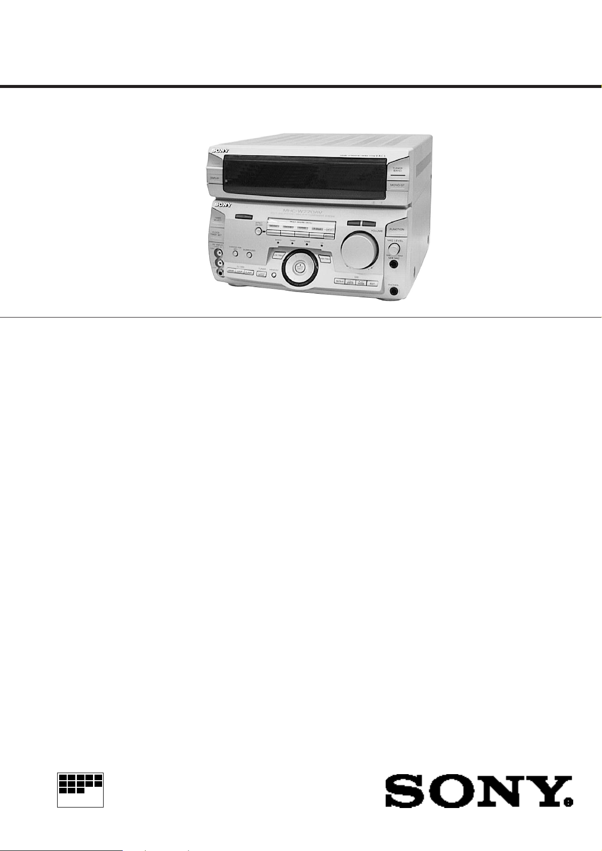
STR-W770 is RECEIVER section in
MHC-W770AV.
Manufactured under license from Dolby Laboratories
Licensing Corporation.
“DOLBY”, “PRO LOGIC” and the double-D symbol a are
trademarks of Dolby Laboratories Licensing Corporation.
SPECIFICATIONS
E Model
Australian Model
T uner section
FM stereo, FM/AM superheterodyne tuner
FM tuner section
Tuning range 87.5-108.0MHz
Aerial FM lead aerial
Aerial terminals 75 ohm unbalanced
Intermediate frequency 10.7MHz
AM tuner section
Tuning range (Thai,Australian,E)
AM: 530-1,710kHz
(with interval set at 10kHz)
531-1,710kHz
(with interval set at 9kHz)
(EXCEPT Thai,Australian,E)
MW: 531-1,602kHz
(with interval set at 9kHz)
(EXCEPT Thai,Australian,E)
SW: 5.95-17.90MHz
(with interval set at 9kHz)
Intermediate frequency 450kHz
Aerial AM loop aerial,
External aerial terminal
Video section
Inputs AV INPUT VIDEO
(phone jack) :
1 Vp-p, 75 ohms
MONITOR OUT
(phone jack) :
1 Vp-p, 75 ohms
Amplifier section
DIN power output 80W +80W
(6 ohms at 1kHz, DIN)
Music power output 190W + 190W
(6 ohms at 1kHz, 10%, THD)
Inputs MD/VIDEO 1 IN (phono jacks) : voltage 250 mV,
impedance 47 kilo ohms AV INPUT AUDIO
(phone jacks) : voltage 250 mV, impedance 47
kilo ohms
MIX/MIC (phone jack) :sensitivity 1mV,
impedance 10 kilo ohms
Outputs MD/VIDEO 1 OUT
(phone jacks) : voltage 250
mV, impedance 1 kilo ohm
PHONES (stereo phone
jack) : accepts headphone
of 8 ohms or more.
SPEAKER : accepts
impedance of 6 to 16
ohms
SUPER WOOFER :
Voltage 1 V, impedance 1
kilo ohms
— Continued on next page —
FM STEREO/FM-AM RECEIVER
MICROFILM
General
Power requirements 240V AC, 50/60 Hz (Australian)
220V AC, 50/60 Hz (Thai)
110 - 120V/220-240V AC adjustable, 50/60 Hz
(OTHER MODEL)
Power consumption 170 watts
Dimensions (w / h / d) Approx. 280 × 205 × 336 mm
Mass Approx. 7.0 kg
Design and specifications are subject to change without notice.
TABLE OF CONTENTS
1. GENERAL ······································································3
2. TEST MODE·································································· 5
3. DIAGRAMS ····································································6
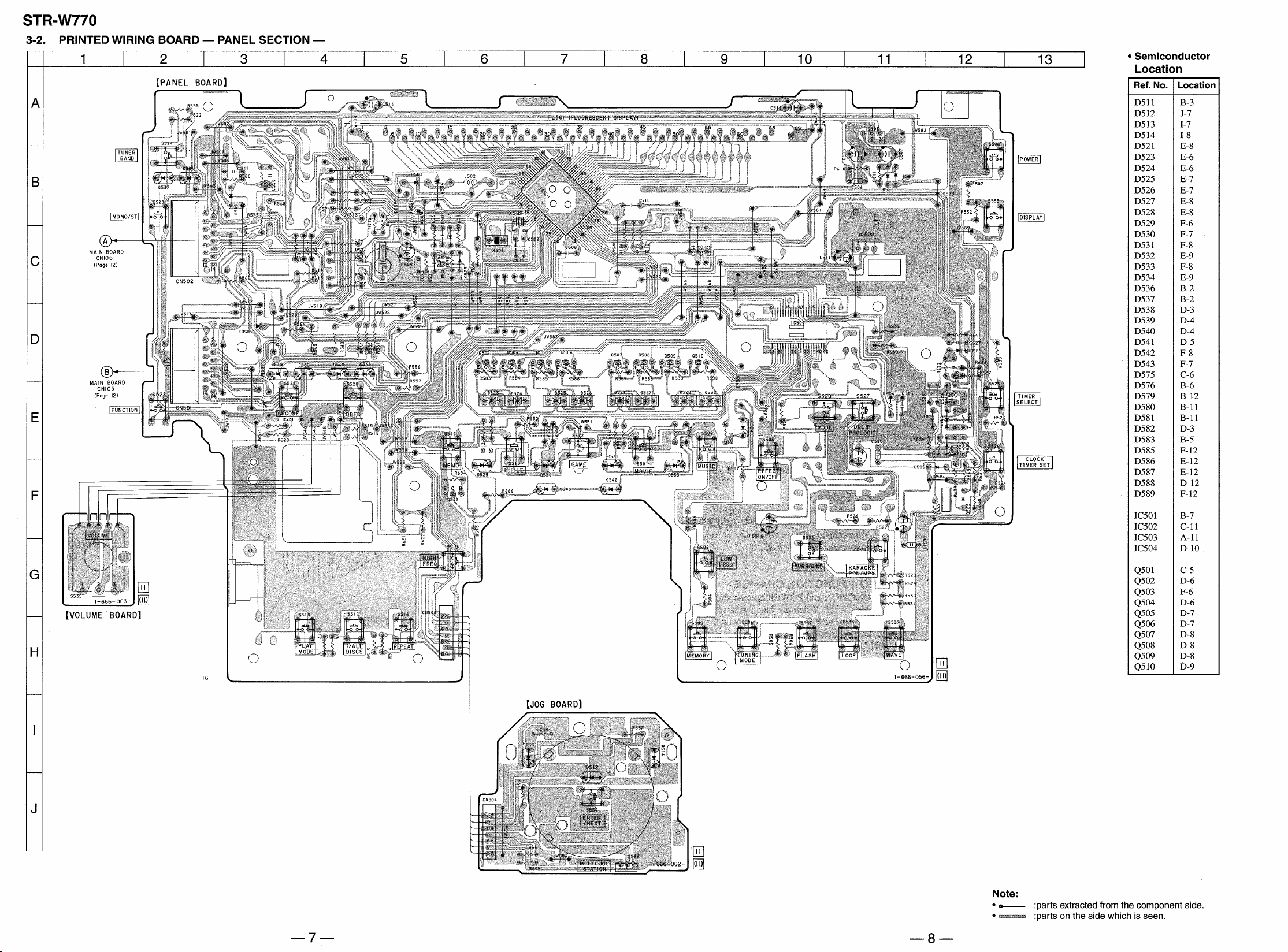
3-1. Circuit Boards Location ····················································· 6
3-2. Printed Wiring Board — Panel Section —·························7
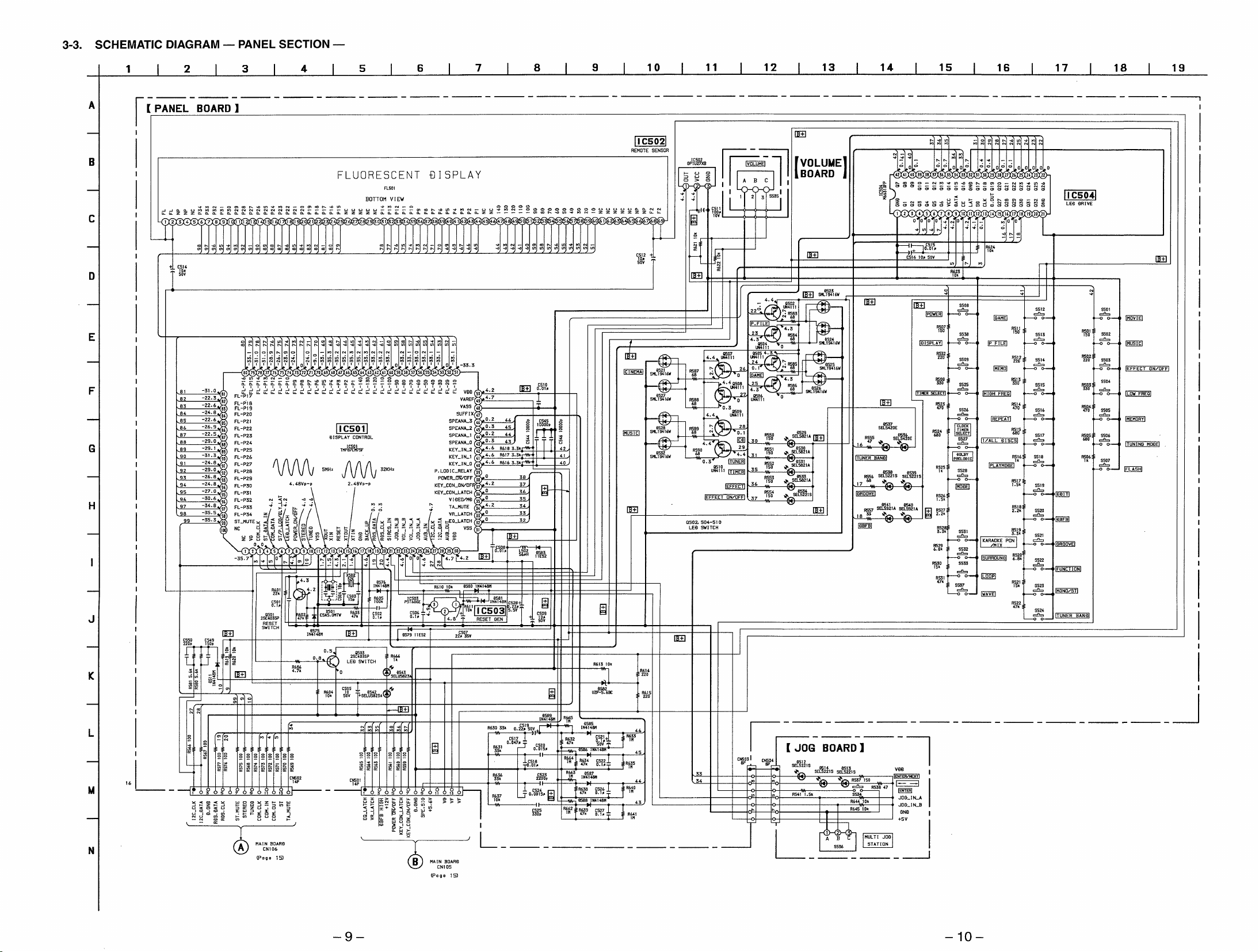
3-3. Schematic Diagram — Panel Section — ··························· 9
3-4. Printed Wiring Board — Main Section — ······················· 12
3-5. Schematic Diagram — Main Section — ·························· 15
3-6. Printed Wiring Board and Schematic Diagram
— Power Section — ························································ 19
3-7. Printed Wiring Board and Schematic Diagram
— Mic Echo/AV in Section — ········································ 23
3-8. Printed Wiring Board and Schematic Diagram
— Power Section — ························································ 26
3-9. IC Pin Function ································································ 29
3-10. IC Block Diagrams ··························································· 31
4. EXPLODED VIEWS
4-1. Main Section····································································· 33
4-2. Panel Section ···································································· 34
5. ELECTRICAL PARTS LIST ··································· 35
Notes on chip component replacement
• Never reuse a disconnected chip component.
• Notice that the minus side of a tentalum capacitor may be damaged
by heat.
SAFETY-RELATED COMPONENT WARNING!!
COMPONENTS IDENTIFIED BY MARK ! OR DOTTED LINE WITH
MARK ! ON THE SCHEMATIC DIAGRAMS AND IN THE PARTS
LIST ARE CRITICAL TO SAFE OPERATION. REPLACE THESE
COMPONENTS WITH SONY PARTS WHOSE PART NUMBERS
APPEAR AS SHOWN IN THIS MANUAL OR IN SUPPLEMENTS
PUBLISHED BY SONY.
MODEL IDENTIFICATION
— Model Number Label —
MODEL IDENTIFICATION
MODEL No.STR-W770
FM STEREO/FM-AM RECEIVER
Australian : AC 240V AC, ~ 50/60Hz 170W
Thai : AC 220V AC, ~ 50/60Hz 170W
OTHER MODEL : AC 110-120V, 220-240V selectable
~ 50/60Hz 170W
— 2 —
— FRONT PANEL —
SECTION 1
GENERAL
123456789!º!¡!™
#¶
#§
#∞
#¢
#£
#™
#¡
1KARAOKE PON/MPX button
2SURROUND button
3EFFECT ON/OFF button
4MUSIC button
5MOVIE button
6GAME button
7P FILE button
8MEMO button
9DBFB button
!ºVOLUME
!¡GROOVE button
!™TUNER BAND button
!£MONO/ST button
!¢FUNCTION button
!∞MIC LEVEL
!§MIX MIC jack
!¶PHONES jack
!•EDIT button
!ªPLAY MODE button
#º
!£
!¢
!∞
!§
!¶
!•!ª@º@¡@™@£@§ @¢@∞@¶@•@ª
@º1/ALL DISCS button
@¡REPEAT button
@™HIGH FREQ button
@£ENTER/NEXT button
@¢MULTI JOG STATION dial
@∞LOW FREQ button
@§MEMORY button
@¶TUNING MODE button
@•FLASH button
@ªLOOP button
#ºWAVE button
#¡AV INPUT jack
#™CLOCK TIMER SET button
#£TIMER SELECT button
#¢DOLBY PROLOGIC button
#∞MODE button
#§DISPLAY button
#¶POWER button
— 3 —
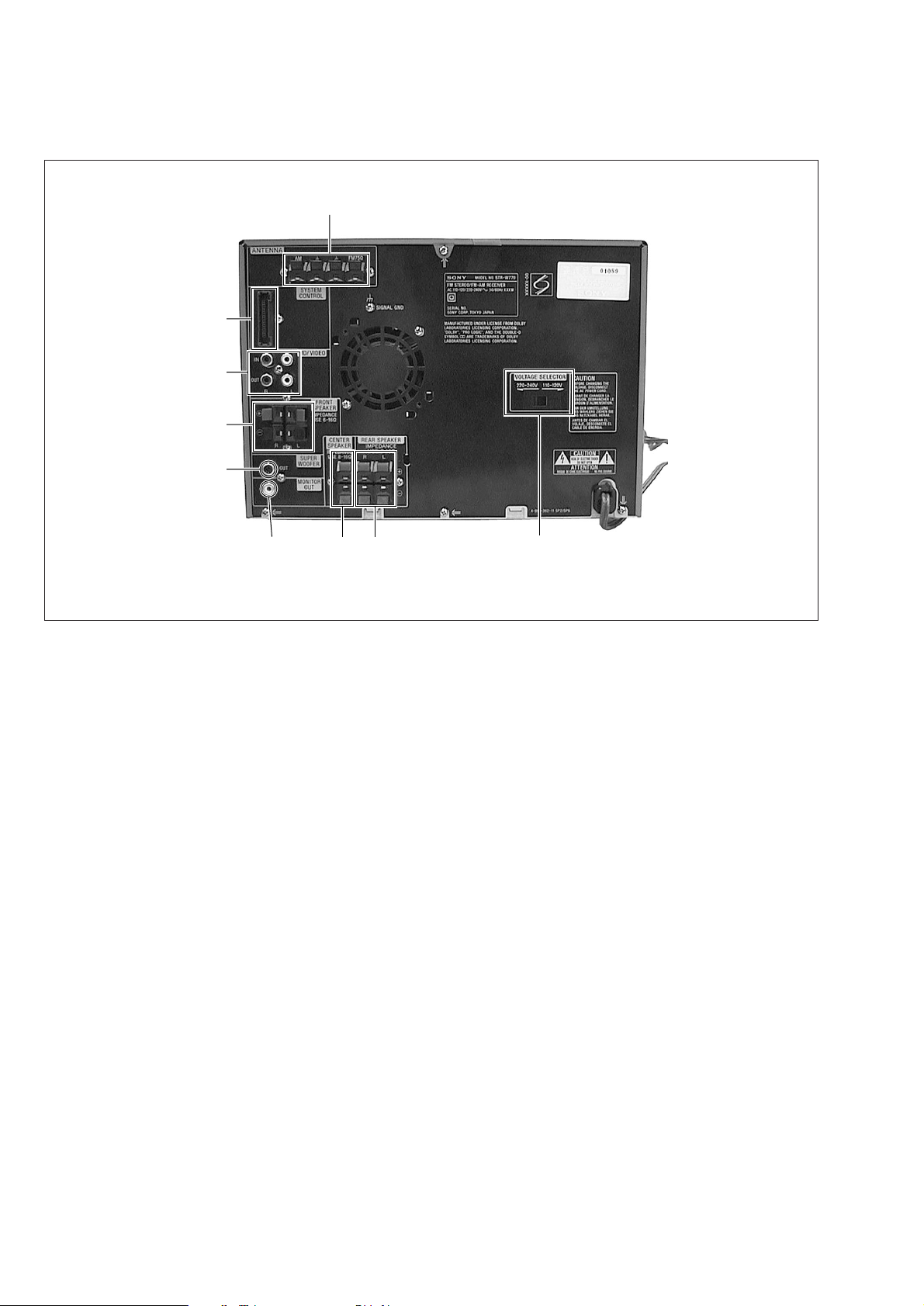
— BACK PANEL —
$§
#•
#ª
$º
$¡
$™
$£ $¢
Photo : E MODEL
$∞
#• SYSTEM CONTROL
#ª MD/VIDEO jack
$º FRONT SPEAKER terminal
$¡ SUPER WOOFER jack
$™ MONITOR OUT jack
$£ CENTER SPEAKER terminal
$¢ REAR SPEAKER terminal
$∞ VOLTAGE SELECTOR switch
(EXCEPT Thai, Australian model)
$§ ANTENNA terminal
— 4 —
SECTION 2
TEST MODE
SECTION 3
DIAGRAMS
FL DISPLAY/KEY LED TEST MODE
Press the REPEA T , ENTER/NEXT and SURR OUND b uttons
sim ultaneousl y.
1. All FL segments and all LEDs turn on.
2. To access the micr opr ocessor inf ormation, press the P FILE
key. Eac h pressing of the P FILE ke y ad vances the displa y on
the FL tube in the f ollo wing sequence .
STR microprocessor version number
HCD microprocessor version number
VCD microprocessor version number (VCD model only)
Model name
Destination
3. T o c hec k the encoder , press the MUSIC ke y. The f ollo wing displa y
appears on the FL tube.
"K0J0V0"
The n umber after K indicates the n umber of times that the ke y is
pressed. The ke y whic h was pressed in the past, is not counted.
The ke y whic h is pressed hereafter is counted. Pressing an y ke y
increases the number after K.
The number after J indicates the number of rotations that the JOG
dial is r otated. T urning the JOG dial c loc kwise increases the n umber
after J . Turning the JOG dial counter -cloc kwise decreases the
number after J.
AGING MODE
1. CD aging mode
T o e xecute the CD a ging, set the three discs to the CD tra y and
set the function to CD . REPEA T , ENTER/NEXT and LOOP
buttons sim ultaneousl y. The CD a ging mode star ts and the disc
calendar starts blinking.
2. Tape a ging mode
T o e xecute the tape a ging, set the tw o tapes to the tape A and B
drives. Set the function to T APE. Press the REPEA T, ENTER/
NEXT and LOOP b uttons sim ultaneousl y. Press the A f orwar d
key to star t the tape a ging mode . "AGING" appear s on the
displa y.
CD SERVICE MODE
T urn on the main po wer. Press the REPEA T , ENTER/NEXT and
KARAOKE PON/MPX b uttons sim ultaneousl y.
V ACS tog gles between ON and OFF .
VACS LEVEL DISPLAY
T urn on the main po wer. Press the EDIT , ENTER/NEXT and
KARAOKE PON/MPX b uttons sim ultaneousl y.
V ACS le vel appear s on the displa y.
CD SHIP MODE
T urn on the main po wer. Press the PLA Y MODE and PO WER
buttons sim ultaneousl y.
The main po wer is turned off and LOCK appear s on the displa y.
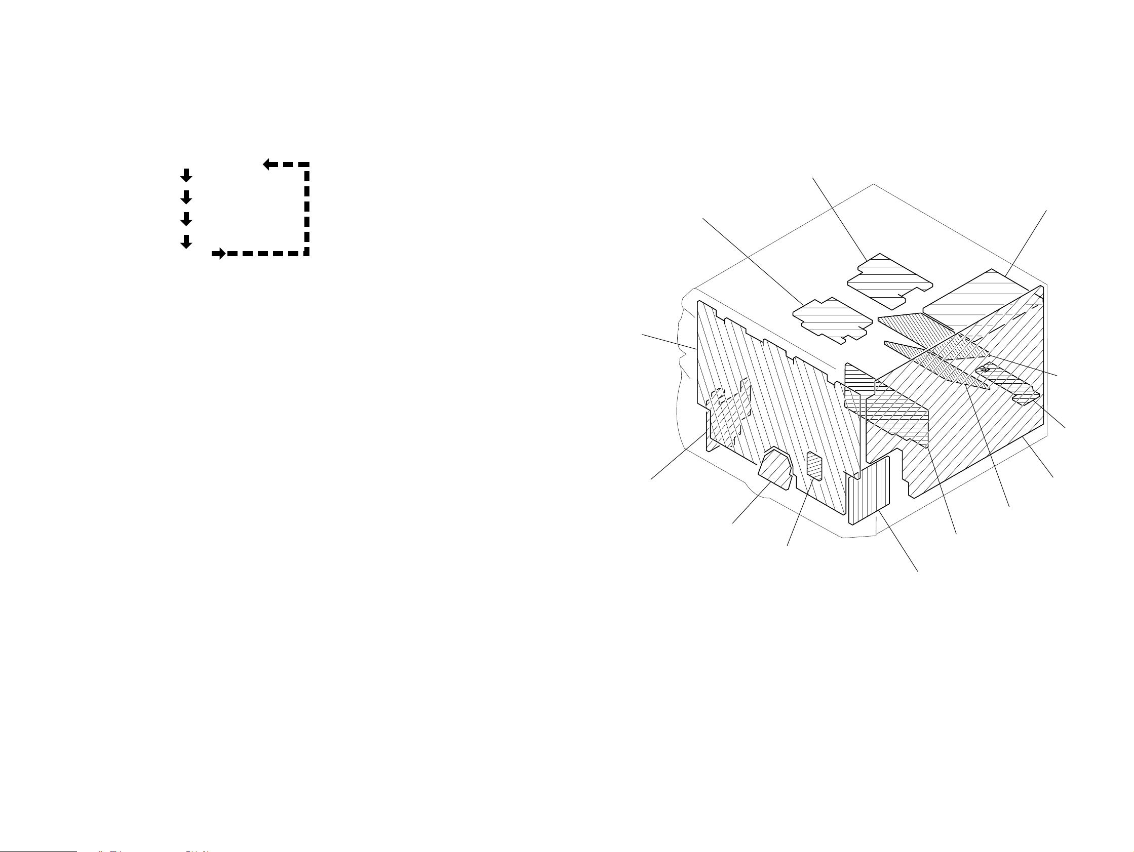
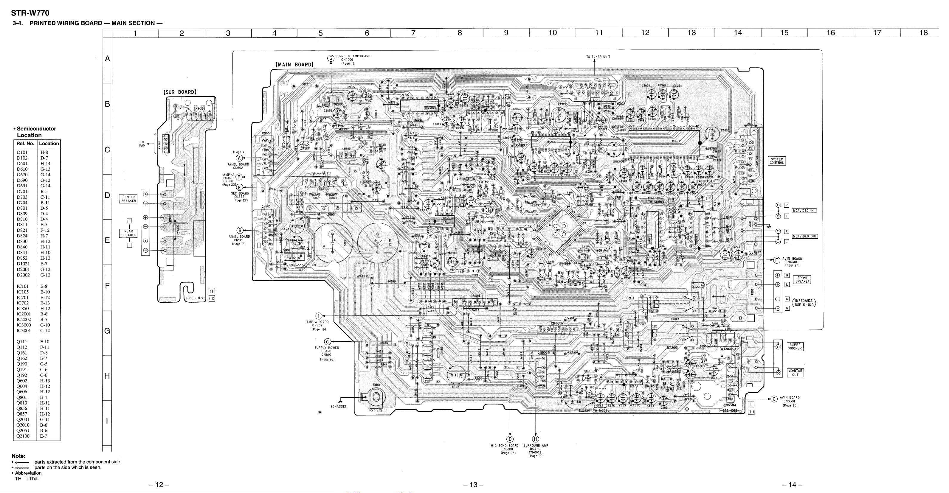
3-1. CIRCUIT BOARDS LOCATION
PRI BOARD
ENCAPSULATED
COMPONENT
SEC BOARD
PANEL BOARD
SURROUND
AMP BOARD
The n umber after V indicates the n umber of r otations that the
V OLUME dial is r otated. T urning the V OLUME dial c loc kwise
increases the n umber after V . Turning the V OLUME dial counter cloc kwise decreases the n umber after V .
T o e xit this mode , perf orm the "Cold Reset" (reset c learing memor y)
as described belo w.
GENERAL TEST MODE
(INCLUDING AMPLIFIER AND TUNER)
Press the REPEA T , ENTER/NEXT and CLOCK TIMER SET
buttons sim ultaneousl y while the main po wer is on.
1. Sound v olume displa y segment star ts b linking.
2. The tuning enters the PRESET mode.
3. Rotating the VOLUME contr ol c loc kwise increases the v olume
level to maxim um.
Rotating the V OLUME contr ol counter -cloc kwise decreases
the v olume le vel to minim um.
4. Pressing the MUSIC ke y decreases the equaliz er cur ve to
minim um and "EQ CHECK" appear s on the displa y.
Pressing the MO VIE key increases the equaliz er cur ve to
maximum.
Pressing the GAME ke y makes the equaliz er cur ve flat.
5. Pressing an y of the DBFB, GROOVE or SURR OUND ke y
disappear s "EQ CHECK" on the displa y.
T o e xit this mode , perf orm the "Cold Reset" (reset c learing memor y)
as described belo w.
TUNER STEP CHANGE
T urn on the main po wer. Set the function to TUNER. Select MW
band from the present tuning.
T urn off the main po wer. Press the ENTER/NEXT and PO WER
buttons sim ultaneousl y. The main po wer is turned on and the
chang ed step appear s on the displa y.
MD/VIDEO 1 FUNCTION CHANGE
Press the FUNCTION and PO WER b uttons sim ultaneousl y while
the main po wer is on. When the function is set to VIDEO 1, the
function is c hang ed to MD and MD appear s on the displa y.
When the function is set to MD , the function is c hang ed to VIDEO
1 and VIDEO 1 appear s on the displa y.
COLD RESET (Reset which clears memory.)
Press the REPEA T, ENTER/NEXT and DISPLA Y buttons
sim ultaneousl y at an y time . The system is reset while c learing
memor y.
HOT RESET
(Reset which does not clear memory.)
Press the REPEA T , ENTER/NEXT and TIMER SELECT b uttons
sim ultaneousl y at an y time . The system is reset without c learing
memor y.
AVIN BOARD
SUR BOARD
MAIN BOARD
AMP-A BOARD
JOG BOARD
SUPPLY BOARD
VOLUME BOARD
MIC ECHO BOARD
— 5 — — 6 —
 Loading...