

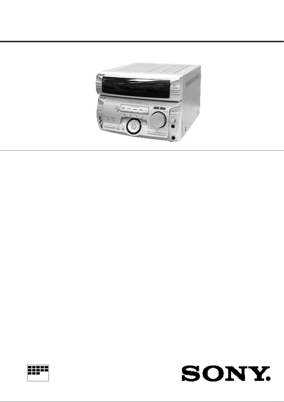
STR-W550
SERVICE MANUAL
STR-W550 is RECEIVER section in
MHC-W550
SPECIFICATIONS
Tuner section
FM stereo, FM/AM superheterodyne tuner
FM tuner section
Tuning range 87.5-108.0MHz (EXCEPT JE)
76.0-108.0MHz (JE)
Aerial FM lead aerial
Aerial terminals 75 ohm unbalanced
Intermediate frequency 10.7MHz
AM tuner section
Tuning range (Canadian,Thai,Argentine,Australian,E2)
AM: 530-1,710kHz
(with interval set at 10kHz)
531-1,710kHz
(with interval set at 9kHz)
(EXCEPT Canadian,Thai,Argentine,
Australian,E2)
MW: 531-1,602kHz
(with interval set at 9kHz)
(AEP,UK)
LW: 153-279kHz
(with interval set at 3kHz)
(EXCEPT AEP ,UK,Canadian,Thai,
Argentine,Australian,E2)
SW: 5.95-17.90MHz
(with interval set at 9kHz)
Intermediate frequency 450kHz
Aerial AM loop aerial,
External aerial terminal
Amplifier section
DIN power output 80W +80W
Music power output 190W + 190W
Inputs MD/VIDEO 1 IN (phono jacks) : voltage 250 mV,
Outputs MD/VIDEO 1 OUT
E2 : Tuner sections SW band do not exist.
Canadian Model
AEP Model
UK Model
E Model
Australian Model
Tourist Model
(6 ohms at 1kHz, DIN)
(6 ohms at 1kHz, 10%, THD)
impedance 47 kilo ohms AV INPUT AUDIO
(phone jacks) : voltage 250 mV, impedance 47
kilo ohms
MIX/MIC (phone jack) :sensitivity 1mV,
impedance 10 kilo ohms
(phone jacks) : voltage 250
mV, impedance 1 kilo ohm
PHONES (stereo phone
jack) : accepts headphone
of 8 ohms or more.
SPEAKER : accepts
impedance of 6 to 16
ohms
SUPER WOOFER :
Voltage 1 V, impedance 1
kilo ohms
— Continued on next page —
Video section
Inputs AV INPUT VIDEO
(phone jack) :
1 Vp-p, 75 ohms
MONITOR OUT
(phone jack) :
1 Vp-p, 75 ohms
MICROFILM
FM STEREO/FM-AM RECEIVER
General
Power requirements 120V AC, 60 Hz (Canadian)
240V AC, 50/60 Hz (Australian)
220V AC, 50/60 Hz (Thai)
220 - 230V AC, 50/60 Hz
(AEP,East European,CIS)
220 - 240V AC, 50/60 Hz (UK)
110 - 120V/220-240V AC adjustable, 50/60 Hz
(OTHER MODEL)
Power consumption 170 watts
Dimensions (w / h / d) Approx. 280 × 205 × 336 mm
Mass Approx. 7.0 kg
Design and specifications are subject to change without notice.
TABLE OF CONTENTS
1. GENERAL
······································································ 3
2. TEST MODE·································································· 5
3. ELECTRICAL ADJUSTMENTS ····························· 6
4. DIAGRAMS
4-1. Circuit Boards Location ····················································· 8
4-2. Printed Wiring Board — Tuner Section — ························ 9
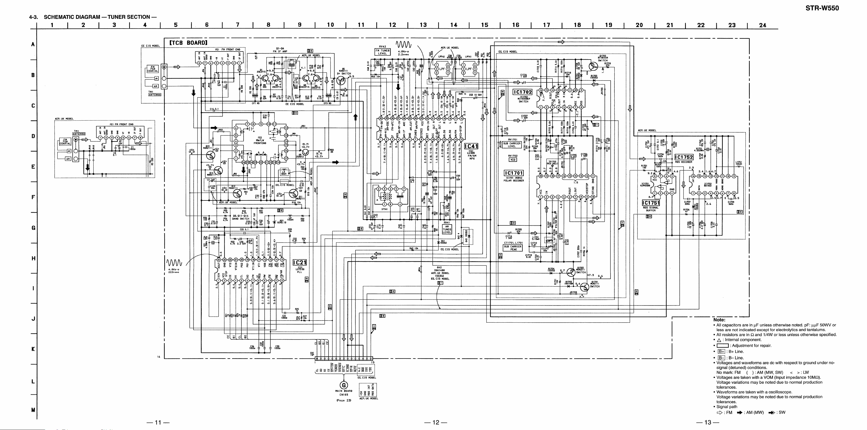
4-3. Schematic Diagram — Tuner Section —························· 11
4-4. Printed Wiring Board — Panel Section —······················· 14
4-5. Schematic Diagram — Panel Section — ························· 17
4-6. Printed Wiring Board — Main Section — ······················· 20
4-7. Schematic Diagram — Main Section — ·························· 23
4-8. Printed Wiring Board and Schematic Diagram
— Power Section —························································· 27
4-9. IC Pin Function ································································ 31
4-10. IC Block Diagrams ··························································· 33
5. EXPLODED VIEWS
5-1. Main Section····································································· 35
5-2. Panel Section ···································································· 36
6. ELECTRICAL PARTS LIST ··································· 37
Notes on chip component replacement
• Never reuse a disconnected chip component.
• Notice that the minus side of a tentalum capacitor may be damaged
by heat.
SAFETY-RELATED COMPONENT WARNING!!
COMPONENTS IDENTIFIED BY MARK ! OR DOTTED LINE WITH
MARK ! ON THE SCHEMATIC DIAGRAMS AND IN THE PARTS
LIST ARE CRITICAL TO SAFE OPERATION. REPLACE THESE
COMPONENTS WITH SONY PARTS WHOSE PART NUMBERS
APPEAR AS SHOWN IN THIS MANUAL OR IN SUPPLEMENTS
PUBLISHED BY SONY .
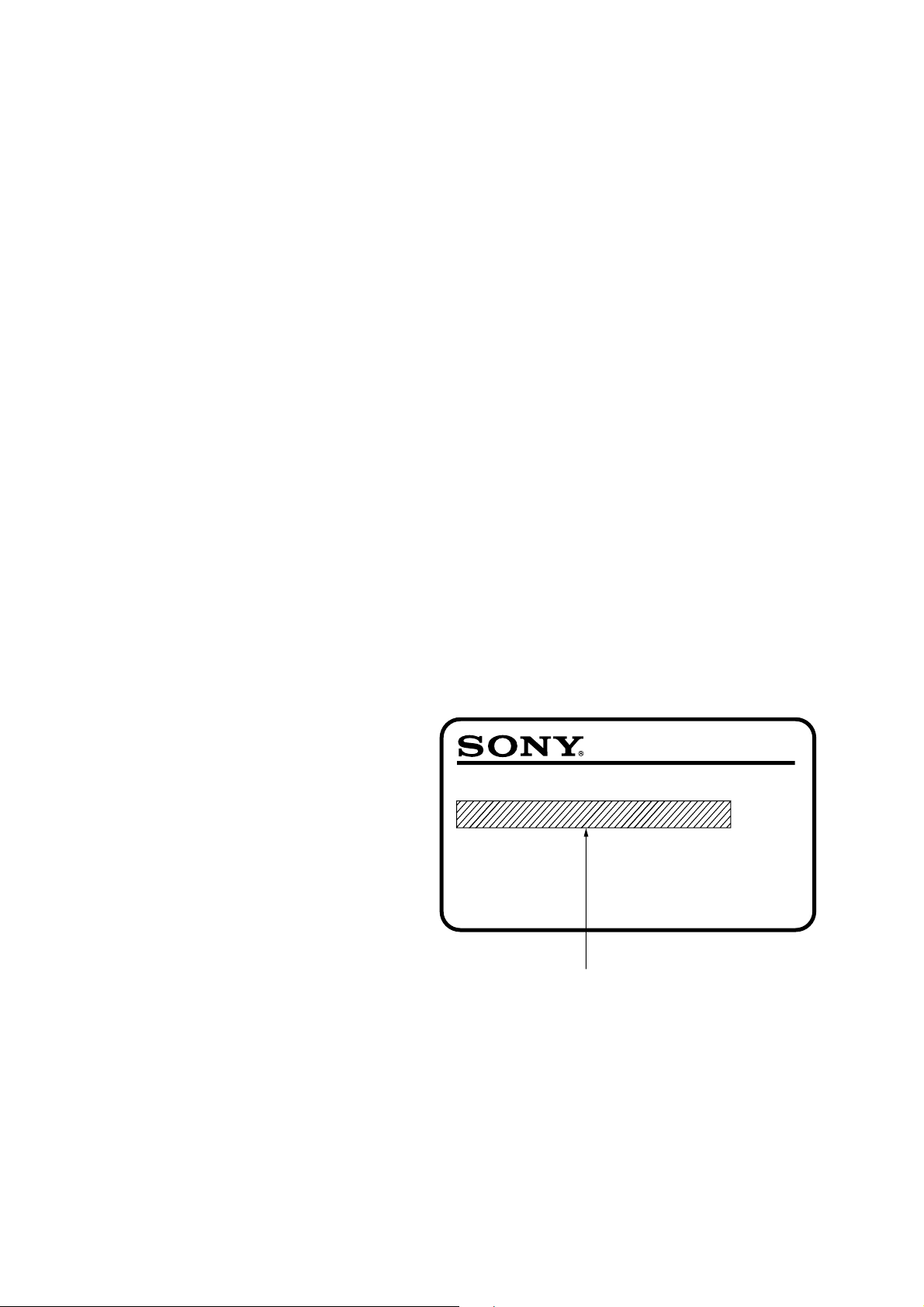
MODEL IDENTIFICATION
— Model Number Label —
MODEL IDENTIFICATION
MODEL NO.STR-W550
FM STEREO/FM-AM RECEIVER
CND : AC 120V AC, ~ 60Hz 170W
AUS : AC 240V AC, ~ 50/60Hz 170W
TH : AC 220V AC, ~ 50/60Hz 170W
AEP, EE, CIS : AC 220-230V ~ 50/60Hz 170W
UK : AC 220-240V ~ 50/60Hz 170W
OTHER MODEL : AC 110-120V, 220-240V selectable
~ 50/60Hz 170W
ATTENTION AU COMPOSANT AYANT RAPPORT
À LA SÉCURITÉ!
LES COMPOSANTS IDENTIFÉS P AR UNE MARQUE ! SUR LES
DIAGRAMMES SCHÉMA TIQUES ET LA LISTE DES PIÈCES SONT
CRITIQUES POUR LA SÉCURITÉ DE FONCTIONNEMENT. NE
REMPLACER CES COMPOSANTS QUE PAR DES PIÈSES SONY
DONT LES NUMÉROS SONT DONNÉS DANS CE MANUEL OU
DANS LES SUPPÉMENTS PUBLIÉS PAR SONY.
• Abbreviations
TH : Thai SP : Singapore AR : Argentine
HK : HongKong EA3 : Saudi Arabia AUS : Australian
TW : Taiwan EA4 : Israel MY : Malaysia
IA : Indonesian JE : Tourist CND : Canadian
EE : East European
E2 : Tuner sections SW band do not exist.
E3 : Tuner sections SW band exist.
— 2 —
— FRONT PANEL —
SECTION 1
GENERAL
1 KARAOKE PON/MPX button
2 SURROUND button
3 EFFECT ON/OFF button
4 MUSIC button
5 MOVIE button
6 GAME button
7 P FILE button
8 MEMO button
9 DBFB button
!º VOLUME
!¡ GROOVE button
!™ TUNER BAND button
!£ MONO/ST button
!¢ FUNCTION button
!∞ MIC LEVEL
!§ MIX MIC jack
!¶ PHONES jack
!• EDIT button
!ª PLAY MODE button
@º 1/ALL DISCS button
@¡ REPEAT button
@™ HIGH FREQ button
@£ ENTER/NEXT button
@¢ MULTI JOG STATION dial
@∞ LOW FREQ button
@§ MEMORY button
@¶ TUNING MODE button
@• FLASH button
@ª LOOP button
#º WAVE button
#¡ AV INPUT jack
#™ CLOCK TIMER SET button
#£ TIMER SELECT button
#¢ RDS button (AEP, UK MODEL)
#∞ DISPLAY button
#§ POWER button
— 3 —
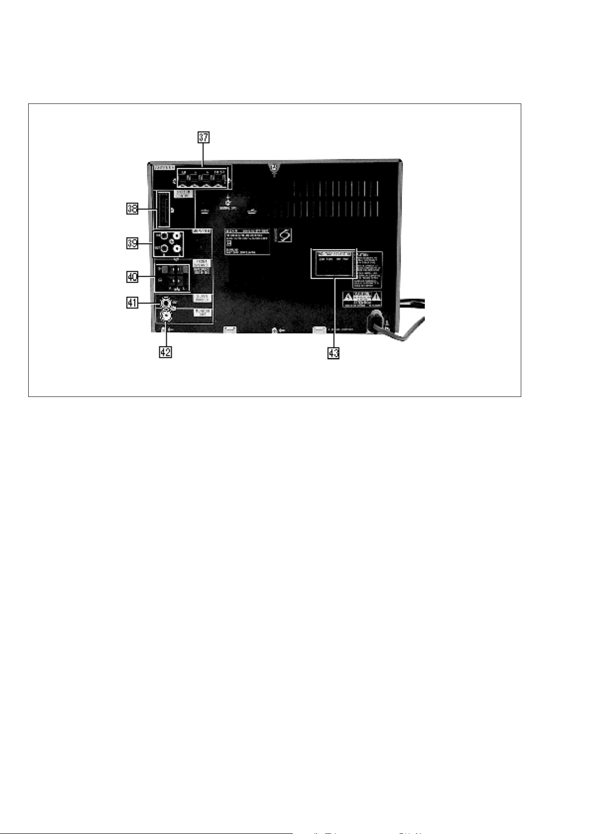
— BACK PANEL —
Photo : E MODEL
#¶ ANTENNA terminal
#• SYSTEM CONTROL
#ª MD/VIDEO jack
$º FRONT SPEAKER terminal
$¡ SUPER WOOFER jack
$™ MONITOR OUT jack
$£ VOLTAGE SELECTOR switch
(E, Saudi Arabia, Singapore, Malaysia, Hong
Kong, Taiwan, Indonesian, Argentine, Tourist
MODEL)
— 4 —
FL DISPLAY/KEY LED TEST MODE
RV42
IC41
RV41
TM1
FE1
l
l
RV41
IC1701
RV42
RV1701
CT1701
TP1702
(VCO)
(FILTER) TP1701
TM1
FE1
+
–
FREQUENCY COUNTER
+
–
LEVEL METER
IC41
L1701
RV1702
Press the REPEAT, ENTER/NEXT and SURROUND buttons
simultaneously.
1. All FL segments and all LEDs turn on.
2. To access the microprocessor information, press the P FILE
key. Each pressing of the P FILE key advances the display on
the FL tube in the following sequence.
STR microprocessor version number
HCD microprocessor version number
VCD microprocessor version number (VCD model only)
Model name
Destination
3. To check the encoder, press the MUSIC key. The following
display appears on the FL tube.
"K0J0V0"
The number after K indicates the number of times that the key is
pressed. The key which was pressed in the past, is not counted.
The key which is pressed hereafter is counted. Pressing any key
increases the number after K.
The number after J indicates the number of rotations that the JOG
dial is rotated. Turning the JOG dial clockwise increases the number
after J. Turning the JOG dial counter-clockwise decreases the
number after J.
The number after V indicates the number of rotations that the
VOLUME dial is rotated. Turning the VOLUME dial clockwise
increases the number after V. Turning the VOLUME dial counterclockwise decreases the number after V.
To exit this mode, perform the "Cold Reset" (reset clearing memory)
as described below.
GENERAL TEST MODE
(INCLUDING AMPLIFIER AND TUNER)
Press the REPEAT, ENTER/NEXT and CLOCK TIMER SET
buttons simultaneously while the main power is on.
1. Sound volume display segment starts blinking.
2. The tuning enters the PRESET mode.
3. Rotating the VOLUME control clockwise increases the volume
level to maximum.
Rotating the VOLUME control counter-clockwise decreases
the volume level to minimum.
4. Pressing the MUSIC key decreases the equalizer curve to
minimum and "EQ CHECK" appears on the display.
Pressing the MOVIE key increases the equalizer curve to
maximum.
Pressing the GAME key makes the equalizer curve flat.
5. Pressing any of the DBFB, GROOVE or SURROUND key
disappears "EQ CHECK" on the display.
To exit this mode, perform the "Cold Reset" (reset clearing memory)
as described below.
SECTION 2
TEST MODE
AGING MODE
1. CD aging mode
To execute the CD aging, set the three discs to the CD tray and
set the function to CD. REPEAT, ENTER/NEXT and LOOP
buttons simultaneously. The CD aging mode starts and the disc
calendar starts blinking.
2. Tape aging mode
To execute the tape aging, set the two tapes to the tape A and B
drives. Set the function to T APE. Press the REPEA T , ENTER/
NEXT and LOOP buttons simultaneously. Press the A forward
key to start the tape aging mode. "AGING" appears on the
display.
CD SERVICE MODE
Turn on the main power. Press the REPEAT, ENTER/NEXT and
KARAOKE PON/MPX buttons simultaneously.
VACS toggles between ON and OFF.
VACS LEVEL DISPLAY
Turn on the main power. Press the EDIT, ENTER/NEXT and
KARAOKE PON/MPX buttons simultaneously.
VACS level appears on the display.
CD SHIP MODE
Turn on the main power. Press the PLAY MODE and POWER
buttons simultaneously.
The main power is turned off and LOCK appears on the display.
TUNER STEP CHANGE
Turn on the main power. Set the function to TUNER. Select MW
band from the present tuning.
Turn off the main power. Press the ENTER/NEXT and POWER
buttons simultaneously. The main power is turned on and the
changed step appears on the display.
MD/VIDEO 1 FUNCTION CHANGE
Press the FUNCTION and POWER buttons simultaneously while
the main power is on. When the function is set to VIDEO 1, the
function is changed to MD and MD appears on the display.
When the function is set to MD, the function is changed to VIDEO
1 and VIDEO 1 appears on the display.
COLD RESET (Reset which clears memory.)
Press the REPEAT, ENTER/NEXT and DISPLAY buttons
simultaneously at any time. The system is reset while clearing
memory.
HOT RESET
(Reset which does not clear memory.)
Press the REPEAT, ENTER/NEXT and TIMER SELECT buttons
simultaneously at any time. The system is reset without clearing
memory.
SECTION 3
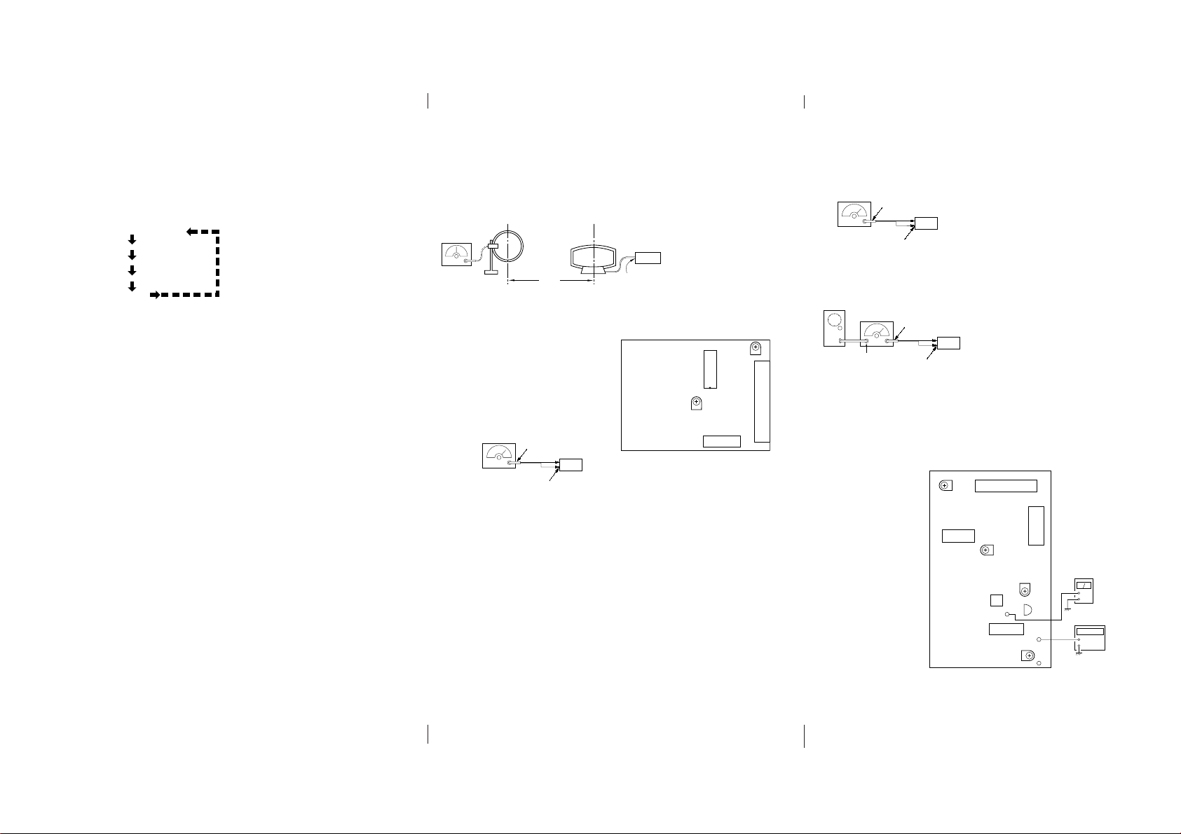
ELECTRICAL ADJUSTMENTS
(AEP, UK, East European, CIS model)
Note: As a front-end (FE1) is difficult to repair if faulty , r eplace it
with new one.
AM Section Adjustment
Setting:
loop antenna
AM RF SSG
30% amplitude
modulation by
400 Hz signal
Field strength dB (
AM Tuned Level Adjustment
Band: AM or MW
Procedure:
1. Set the output of SSG so that the input level of the set becomes
55 dB.
2. Tune the set to 999 kHz.
3. Adjust RV41 to the point (moment) when the TUNED indicator
will change from going off to going on.
Adjustment Location : TCB board
FM Section Adjustment
Note: This adjustment should be performed after the AM Tuned
Level Adjustment due to the same adjustment element.
Setting:
FM RF stereo signal
generator
Carrier frequency : 98 MHz
Modulation : AUDIO 1 kH, 75 kHz
deviation (100%)
FM Tuned Level Adjustment
Band: FM
Procedure:
1. Supply a 25 dBµ 98 MHz signal from the ANTENNA terminal.
2. Tune the set to 98 MHz.
3. If the TUNED indicator does not light, adjust RV42 to the point
(moment) when the TUNED indicator will change from going
off to going on.
Adjustment Location: TCB board
75
loop antenna
(Supplied accessories)
60 cm
µ
V/m) =SSG output level dB (µV/m) –26 dB.
Ω
coaxial
set
FM ANTENNA termina
(TM1) (75 Ω open)
set
AM ANTENNA
terminal (TM1)
Adjustment Location:
[TCB BOARD] (Component Side)
(East European, CIS model)
FM Polar Adjustment
FM RF SSG
Ω
coaxial
75
FM ANTENNA termina
(75 Ω)
set
Connection 1:
Carrier frequency : 69 MHz
Output level : 1mV (60dBµ) (at 75 Ω open)
Modulation : AUDIO 1 kHZ, 10kHz deviation
AF OSC
FM RF SSG
75
Ω
coaxial
Audio 31.25 kHz
Connection 2:
external
modulation
terminal
Carrier frequency : 69 MHz
Output level : 1mV (60 dBµ) (at 75 Ω open)
Modulation : AUDIO 31.25 kHZ, 10 kHz deviation
(EXTERNAL MODULATION)
set
FM ANTENNA terminal
Ω
)
(75
Adjustment Location : (East European, CIS model)
[TCB BOARD] (Component Side)
RV41
AM tuned level
Adjustment
RV1701, TP1701
Sub carrier level
Adjustment
CT1701, L1701, TP1701
Sub carrier peak
Adjustment
RV1702, TP1702
VCO Adjustment
Procedure :
1. Set the modulation of FM RF SSG to AUDIO 1 kHz, 10 kHz
deviation according to "Connection 1".
2. Tune the set to 69 MHZ.
3. Adjust the RV1702 so that the reading of frequency counter
connected to TP1702 becomes within 31.25 kHz ± 0.05
kHz.(VCO adjustment)
4. Then record the reading of the level meter connected to TP1701
5. Set the modulation of FM RF SSG to AUDIO 31.25 kHz, 10
kHz deviation according to "Connection 2".
6. Tune the set to 69 MHz.
7. Set the CT1701 to be mechanical center.
8. Adjust the L1701 so that the reading of the level meter connected
to TP1701 become maximum.
Then adjust the CT1701 so that the reading of the level meter
connected to TP1701 becomes maximum. (SUB CARRIER
PEAK Adjustment)
9. Adjust the RV1701 so that the level at the moment becomes
14dB higher value than the level recorded in step 4. (SUB
CARRIER LEVEL Adjustment)
RV42
FM tuned level
Adjustment
– 5 – – 6 – – 7 –
STR-W550
4-1. CIRCUIT BOARDS LOCATION
SECTION 4
DIAGRAMS
4-2. PRINTED WIRING BOARD — TUNER SECTION —
(AEP, UK)
12
3456
A
(East European, CIS)
12
A
3456
PANEL BOARD
AVIN BOARD
SEC BOARD
JOG BOARD
PRI BOARD
MIC ECHO BOARD
DUMMY BOARD
TCB BOARD (AEP, UK, EE, CIS MODEL)
ENCAPSULATED COMPONENT
(EXCEPT AEP, UK, EE, CIS MODEL)
MAIN BOARD
AMP BOARD
B
C
D
E
F
G
H
I
J
Note:
:parts extracted from the component side.
•
:parts on the side which is seen.
•
• Semiconductor
Location
Ref. No. Location
D21 G-2
D41 G-3
D42 H-5
D1751 I-4
IC21 G-2
IC41 E-4
IC1751 I-2
IC1752 I-4
Q1 F-2
Q2 F-2
Q3 E-3
Q4 E-2
Q5 E-3
Q9 D-2
Q11 C-4
Q12 B-4
Q13 B-3
Q14 B-3
B
C
D
E
F
G
H
I
J
— 8 — — 9 — — 10 —
Note:
:parts extracted from the component side.
•
:parts on the side which is seen.
•
• Semiconductor
Location
Ref. No. Location
D21 G-2
D41 G-4
D42 H-5
D43 H-5
D1701 J-4
D1702 J-4
D1703 H-4
D1704 J-4
IC21 G-3
IC41 E-5
IC1701 I-3
IC1702 I-3
Q1 F-3
Q2 F-3
Q4 E-3
Q5 E-3
Q9 D-3
Q11 C-5
Q12 B-5
Q13 B-4
Q14 B-4
Q1701 I-3
Q1702 I-4
Q1703 J-4
 Loading...