

Sony STRVE-250 Service manual
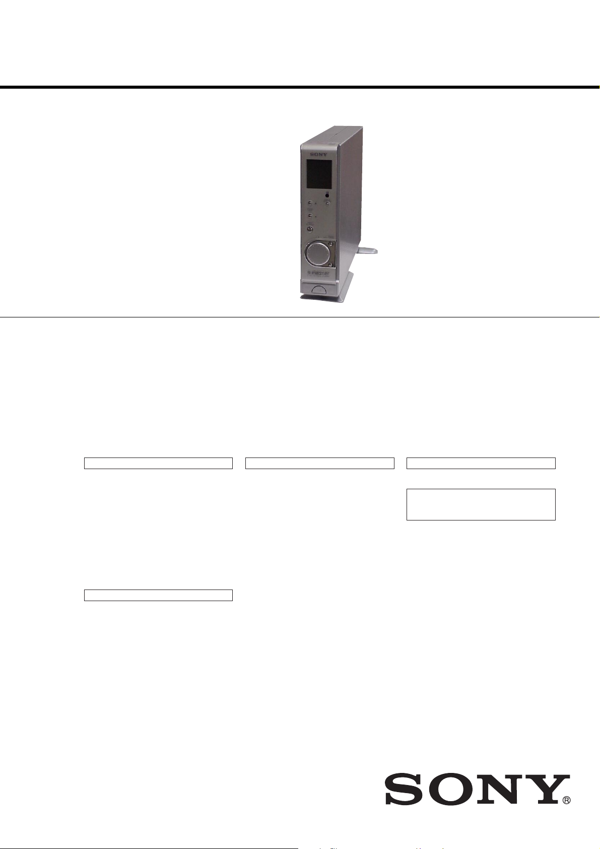
STR-VE250
SERVICE MANUAL
Ver 1.0 2003. 08
• This set is the Amplifier section in
HT-K250.
This system incorporates Dolby* Digital and Pro
Logic Surround and the DTS** Digital Surround
System.
* Manufactured under license from Dolby
Laboratories.
“Dolby”, “Pro Logic” and the double-D symbol are
trademarks of Dolby Laboratories.
**“DTS” and “DTS Digital Surround” are registered
trademarks of Digital Theater Systems, Inc.
AEP Model
UK Model
E Model
Amplifier section
Inputs (Digital)
AUX (Coaxial) Impedance: 75 ohms
DVD, SAT (Optical) S/N: 90 dB
Inputs (Analog)
TV, VIDEO Sensitivity: 700 mV
AM tuner section
Tuning range 531 kHz – 1,602 kHz
Antenna Loop antenna
Usable sensitivity 50 dB/m (at 999 kHz)
S/N 54 dB (at 50 mV/m)
Harmonic distortion 1.0% (50 mV/m, 400 Hz)
S/N: 90 dB
(A, 20 kHz LPF)
(A, 20 kHz LPF)
Impedance: 50 kohms
S/N: 84 dB
(A, 20 kHz LPF)
(With 9-kHz tuning scale)
SPECIFICATIONS
FM tuner section
Tuning range 87.50 MHz – 108.0 MHz
Antenna terminals 75 ohms, unbalanced
S/N
Mono:
Stereo: dB
Sensitivity
Mono: 18.3 dBf, 2.2 µV/7 5 o hms
Stereo: 38.3 dBf, 22.5 µV/7 5 o hms
Useable sensitivity 11.2 dBf, 1 µV/75 ohms
Harmonic distortion at 1 kHz
Mono: 0.3%
Stereo: 0.5%
Separation 45 dB at 1 kHz
Frequency response 30 Hz – 15 kHz,
Selectivity 60 dB at 400 kHz
76
dB
70
+0.5/–2 dB
General
Power requirements
Power voltage is DC 12V, 5.6V and fed with
sub
woofer (SA-WMSP250) from external
CONTROL jack.
Dimensions (w/h/d)
Control center: 58
Control center (with the stand):
Mass (Approx.)
Control center: 1.3 kg
Control center (with the stand):
× 215 × 308
130 × 233 × 308 mm
1.4 kg
mm
9-961-121-01
2003H1678-1
© 2003.08
HOME THEATER SYSTEM
Sony Corporation
Home Audio Company
Published by Sony Engineering Corporation

STR-VE250
TABLE OF CONTENTS
1. GENERAL ········································································· 3
2. TEST MODE ····································································· 5
3. DIAGRAMS ········································································ 7
3-1. PRINTED WIRING BOARD – MAIN SECTION – ····· 8
3-2. SCHEMATIC DIAGRAM – MAIN SECTION – ·········· 9
3-3. PRINTED WIRING BOARD
– FRONT PANEL SECTION – ············ 10
3-4. SCHEMATIC DIAGRAM
– FRONT PANEL SECTION – ············ 11
3-5. IC PIN FUNCTION DESCRIPTION ··························· 12
3-6. IC BLOCK DIAGRAM ················································ 13
4. EXPLODED VIEWS
4-1. MAIN SECTION ·························································· 14
4-2. FRONT PANEL SECTION ·········································· 15
5. ELECTRICAL PARTS LIST ····································· 16
[When bringing in the equipment for service]
When bringing the system in for repairs, be sure to bring in the
entire system (control center (STR-VE250) and subwoofer (SAWMSP250) This product is system product, and the entire system
is needed to determine the location requiring repair.
: LEAD FREE MARK
Unleaded solder has the following characteristics.
• Unleaded solder melts at a temperature about 40°C higher than
ordinary solder.
Ordinary soldering irons can be used but the iron tip has to be
applied to the solder joint for a slightly longer time.
Soldering irons using a temperature regulator should be set to
about 350°C.
Caution: The printed pattern (copper foil) may peel away if the
heated tip is applied for too long, so be careful!
• Strong viscosity
Unleaded solder is more viscous (sticky, less prone to flow) than
ordinary solder so use caution not to let solder bridges occur such
as on IC pins, etc.
• Usable with ordinary solder
It is best to use only unleaded solder but unleaded solder may
also be added to ordinary solder.
Notes on chip component replacement
•Never reuse a disconnected chip component.
• Notice that the minus side of a tantalum capacitor may be dam-
aged by heat.
Flexible Circuit Board Repairing
•Keep the temperature of soldering iron around 270˚C
during repairing.
• Do not touch the soldering iron on the same conductor of the
circuit board (within 3 times).
• Be careful not to apply force on the conductor when soldering
or unsoldering.
2
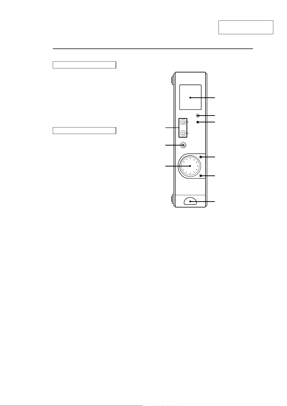
Control center
ALPHABETICAL ORDER
Display 1 (17)
DISPLAY POSITION 3 (18)
INPUT SELECTOR 8 (16, 18, 19)
MUTING 5 (16, 30)
Remote sensor 2
SOUND FIELD f/F 9
VOL/PRESET TUNING 4 (19)
VOL/PRESET TUNING control
7 (16, 19, 27)
NUMBERS AND SYMBOLS
?/1 (power) 6
SECTION 1
GENERAL
9
8
STR-VE250
This section is extracted
from instruction manual.
1
2
3
7
4
5
6
3
STR-VE250
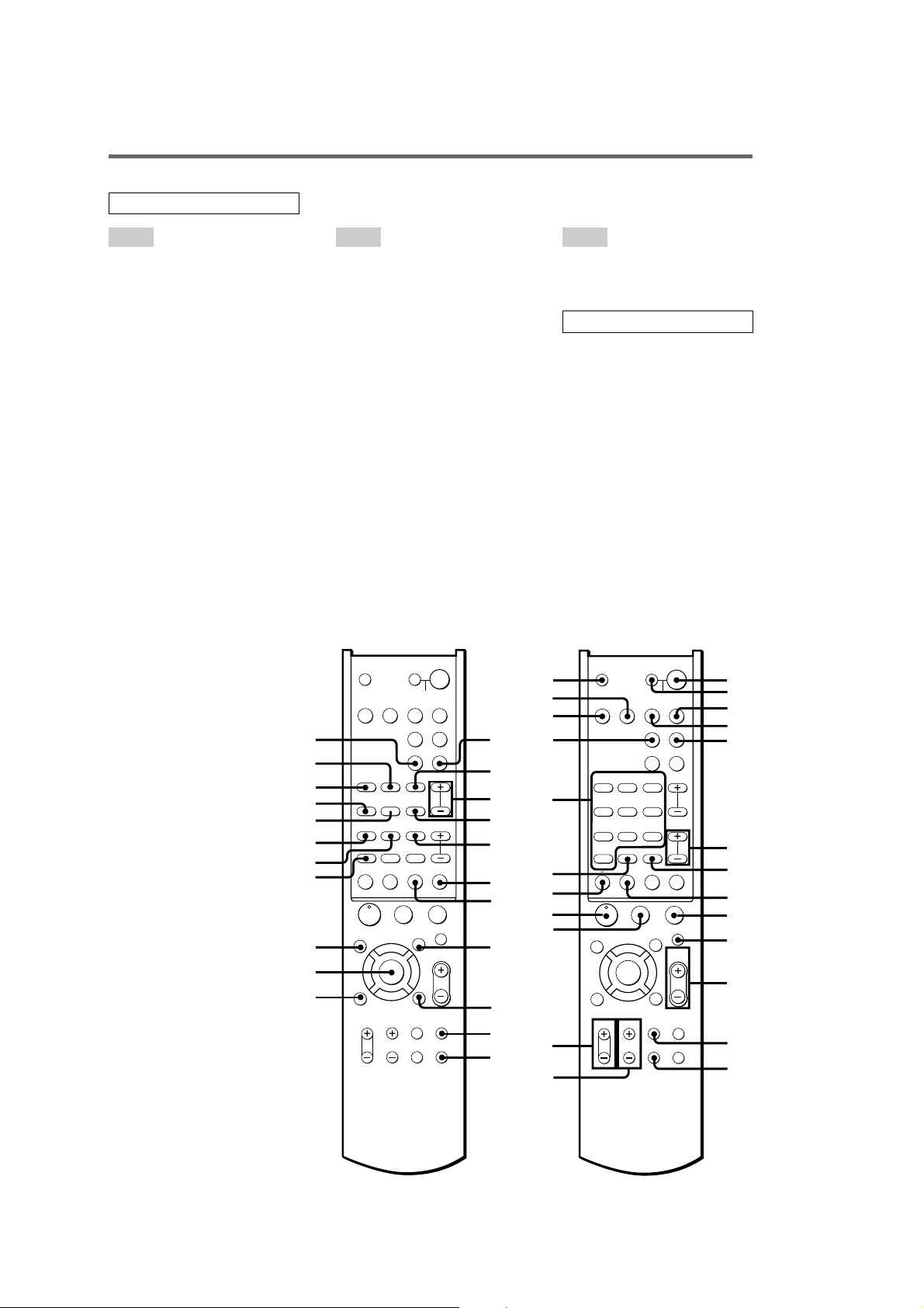
Remote control
ALPHABETICAL ORDER
A – N P – T V – W
A.F.D. wg
AAC BI-LING rf
ALT e; (18, 19, 20, 23)
ANGLE rs
ANT qk
AUDIO rd
AUX wa (16, 25, 31)
AV ?/1 (power) 2 (25)
AV MENU es
CLEAR 8
D.TUNING wh (18)
DISC ea
DISPLAY eh (31)
DVD wd (16, 25, 31)
ENTER/12 7
FM MODE rg (19)
JUMP wl
MAIN MENU ef (22, 26, 27, 28)
MASTER VOL +/– qa (15, 16,
25, 27)
MEMORY ql (19)
MUTING q; (16, 30)
Numeric buttons w; (18, 19, 20,
25)
;PL/PLII rh
PRESET/CH/D.SKIP +/– 6 (20)
RETURN O/EXIT ed
SAT 4 (16, 25, 31)
SEARCH MODE ea
SHIFT 7 (19, 20)
SLEEP 1 (23)
SOUND FIELD +/– wj (21, 30)
SUBTITLE wk
SWAP r;
TEST TONE eg (15, 27)
TIME ra
TOP MENU/GUIDE ek
TUNER 5 (16, 18, 19, 20, 25)
TUNING + 8 (18, 19)
TUNING – qk (18, 19)
TV 3 (16, 25)
TV CH +/– qf
TV VOL +/– qg
TV/VIDEO qs
TV ?/1 (power) wf
SYSTEM STANDBY
SAT TV
AUX TUNER
;
PL/PLII A.F.D.
D.TUNING
SUBTITLE
+
-
SEARCH MODE
X
AV MEN
F
f
O
RETURN/EXIT
TV/
VIDEO
WIDE TEST TONE
?/1
SLEEP
SOUND
FIELD
PRESET/
CH/D.SKIP
x
MUTING
U
MASTER
VOL
MAIN
MENU
rh
rg
rf
rd
rs
ra
r;
el
ek
ej
eh
TV ?/1 AV ?/1
VIDEO DVD
AAC
BI-LING
FM MODE
123
AUDIO ANGLE
456
TIME SWAP JUMP
789
MEMORY SHIFT
>
.
0/10 >10/11 ENTER/12
–
TUNING DISC ALT
M
m
ANT
CLEAR
N
TOP MENU/
GUIDE
ENTER
Gg
DISPLAY
TV VOL TV CH
wg
wh
wj
wk
wl
e;
ea
es
ed
ef
eg
VIDEO ws (16, 25)
WIDE qd
NUMBERS AND SYMBOLS
?/1 (power) 1
V/v/B/b ej (22, 26, 27, 28)
M 8 (24)
m qk (24)
> ql
. el
N qj
X qh
x 9
-/-- ea
0/10 el (25)
>10/11 ql
TV ?/1 AV ?/1
wf
wd
ws
wa
w;
ql
qk
qj
qh
qg
SYSTEM STANDBY
VIDEO DVD
AAC
BI-LING
AUDIO ANGLE
TIME SWAP JUMP
.
m
ANT
TOP MENU/
GUIDE
DISPLAY
TV VOL TV CH
SAT TV
AUX TUNER
;
PL/PLII A.F.D.
FM MODE
D.TUNING
123
SUBTITLE
456
789
MEMORY SHIFT
0/10 >10/11 ENTER/12
–
TUNING DISC ALT
N
Gg
>
M
CLEAR
F
ENTER
f
+
X
RETURN/EXIT
CH/D.SKIP
-
SEARCH MODE
AV MEN
U
O
TV/
VIDEO
WIDE TEST TONE
qf
?/1
SLEEP
SOUND
FIELD
PRESET/
x
MUTING
MASTER
VOL
MAIN
MENU
1
2
3
4
5
6
7
8
9
0
qa
qs
qd
4
SECTION 2
TEST MODE
Note:
Before loading test mode. Be sure to bring in the entire system (control center (STR-VE250) and subwoofer(SAWMSP250)). This product is system product, and the entire system is needed to determine the location requiring
repair.
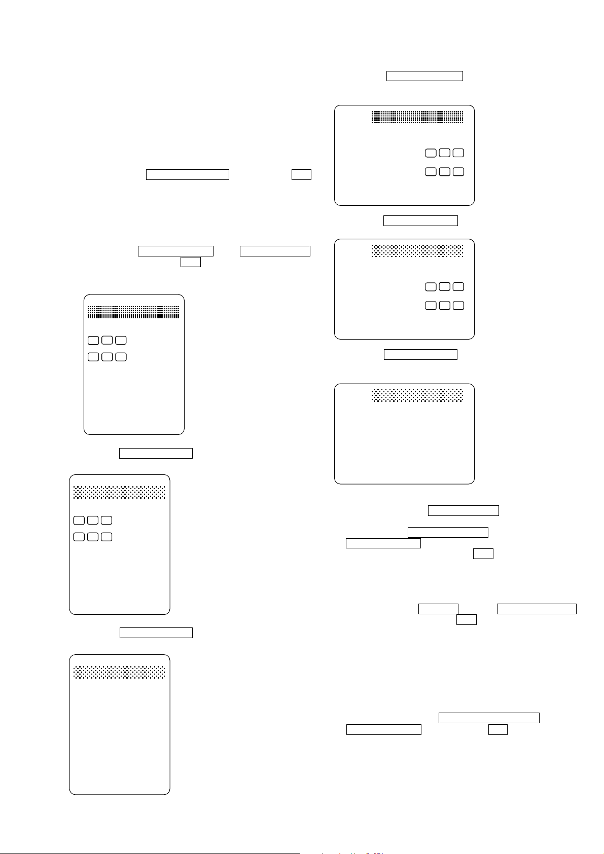
[Software Version Display Mode]
*The software version is displayed.
Procedure:
While depressing the DISPLAY POSITION button, press the ?/1
button to turn on the main power. The destination and the software
version are displayed for four seconds.
STR-VE250
4. Press the SOUND FIELD v button, all segments turn on
(Holizontal display).
FM
AM
STEREO dBMHz
MEMORY
C
L
()
SW L.F.E.(
SL S SR
DTS AAC
DIGITAL
;
PL II
;
KHzmftMONO
R
)
[Liquid Crystal Display Test Mode]
* Liquid Crystal Display is tested when this test is activated.
Procedure:
While depressing the DISPLAY POSITION and the INPUT SELECTOR
buttons simultaneously, press the ?/1 button to turn on the main power.
1. All segments turn on (Vertical display).
FM STEREO dB MHz
AM
C
L
()
SL S SR
DIGITAL
;
PL II
;
R
MEMORY
DTS AACSW L.F.E.(
)
KHzmftMONO
2. Press the SOUND FIELD v button, confirm the display.
FM dBMHz
DIGITAL
;
PL
;
mMONO
MEMORY
DTSSW
5. Press the SOUND FIELD v button, confirm the display.
FM
dBMHz
mMONO
MEMORY
SW
DTS
DIGITAL
;
PL
;
6. Press the SOUND FIELD v button, confirm the display.
AM
STEREO
L
SL S SR
KHzft
C
R
()
)
L.F.E.(
AAC
II
7. Every pressing of the SOUND FIELD v button turns on each
segment one after another in the same order.
(not only the SOUND FIELD v button, but also the
SOUND FIELD V button can be used.)
8. To exit from this mode, press the ?/1 button.
3. Press the SOUND FIELD v button, confirm the display.
STEREO
AM
C
L
()
SL S SR
II
KHzft
R
AACL.F.E.(
)
[All Clear Mode]
* All preset contents are cleared when this mode is activated.
Procedure:
While depressing the MUTING and the INPUT SELECTOR
buttons simultaneously, press the ?/1 button to turn on the main
power. The message “INITIAL” is displayed for four seconds and
initialization is performed.
[Sound Field Clear Mode]
*The preset sound field is cleared when this mode is activated.
Use this mode before returning the product to clients upon
completion of repair.
Procedure:
1. While depressing the VOL/PRESET TUNING and the
SOUND FIELD v buttons, press the ?/1 buttonS to turn on
the main power.
2. The message “SURR.CLR” appears and initialization is
performed.
5

STR-VE250
[DSP Test]
* DSP communication parameter swap mode is set when this mode
is activated.
Procedure:
While depressing the DISPLAY POSITION and the SOUND FIELD V
buttons simultaneously, press the ?/1 button to turn on the main power.
1. The message “DSP TEST” is displayed.
2. Press the VOL/PRESET TUNING button, the message “SWAP
ALL” is displayed and DSP swap mode is set to ALL.
3. Press the VOL/PRESET TUNING button, the message “SWAP
CSW” is displayed and DSP swap mode is set to CSW.
4. Press the VOL/PRESET TUNING button, the message “SWAP
SLR” is displayed and DSP swap mode is set to SLR.
5. Press the VOL/PRESET TUNING button, the message “SWAP
NRM” is displayed and DSP swap mode is set to OFF.
6. To exit from this mode, press the ?/1 button.
[Key Test]
* All keys (without the ?/1 button) are tested when this mode is
activated.
Procedure:
While depressing the MUTING and the SOUND FIELD v
buttons simultaneously, press the ?/1 button to turn on the main
power.
1. The message “123456” is displayed. If the button corresponding to the following number is pressed, the number on the display will be turned off.
2. To exit from this mode, press the ?/1 button.
Key numbers
1 : DISPLAY POSITION ,
2 : MUTING ,
3 : VOL/PRESET TUNING ,
4 : INPUT SELECTOR ,
5 : SOUND FIELD v ,
6 : SOUND FIELD V
6
 Loading...