

Sony STRV-7700 Service manual
STR-V7700
SERVICE MANUAL
STR-V7700 is RECEIVER section in
MHC-V7700AV.
Manufactured under license from Dolby Laboratories
Licensing Corporation.
“DOLBY”, “PRO LOGIC” and the double-D symbol a are
trademarks of Dolby Laboratories Licensing Corporation.
SPECIFICATIONS
Amplifier section
Continuous RMS power output
FRONT SPEAKER:
China model 100+100 watts
6 ohms at 1 kHz, 10%
THD (240V AC supply)
85+85 watts
6 ohms at 1 kHz, 10%
THD (220V AC supply)
Other models 100+100 watts
(6 ohmsat 1 kHz,10%
THD)
CENTER SPEAKER:
45watts (reference)
(8 ohms at 1 kHz, 10%
THD)
REAR SPEAKER:
30+30 watts (reference)
(8 ohms at 1 kHz, 10%
THD)
Peak music power output:
1800 watts (reference)
Inputs MD/VIDEO 1 IN (phono
jacks): voltage 250 mV,
impedance 47 kilo ohms
AV INPUT AUDIO
(phono jacks): voltage 250
mV, impedance 47 kilo
ohms
MIX MIC 1/2 (phone
jack): sensitivity 1 mV,
impedance 10 kilo ohms
Outputs MD/VIDEO 1 OUT
(phono jacks): voltage 250
mV, impedance 1 kilo ohm
PHONES (stereo phone
jack): accepts headphones
of 8 ohms or more.
Video section
Inputs AV INPUT VIDEO
Outputs MONITOR OUT (phono
Tuner section
FM stereo, FM/AM superheterodyne tuner
FRONT SPEAKER:
accepts impedance of 6 to 16
ohms
CENTER SPEAKER:
accepts impedance of 8 to 16
ohms
REAR SPEAKER:
accepts impedance of 8 to 16
ohms
SUPER WOOFER:
Voltage 1 V, impedance 1
kilo ohm
(phono jack):
1 Vp-p, 75 ohms
VIDEO IN (phono jack):
1 Vp-p, 75 ohms
jack): 1 Vp-p, 75 ohms
VIDEO OUT (phono
jack): 1 Vp-p, 75 ohms
S-VIDEO (4-pin/miniDIN jack):
Y: 1 Vp-p, unbalanced,
sync negative
C: 0.286 Vp-p, load
impedance 75 ohms
E Model
Chinese Model
FM tuner section
Tuning range 87.5-108.0 MHz
Antenna terminals 75 ohm unbalanced
Intermediate frequency 10.7 MHz
AM tuner section
Tuning range
Thai models: 531-1,602 kHz
(with the AM tuning
interval set at 9 kHz)
530-1,710 kHz
(with the AM tuning
interval set at 10 kHz)
Other models: MW
531-1,602 kHz
(with the MW tuning
interval set at 9 kHz)
530-1,710 kHz
(with the MW tuning
interval set at 10 kHz)
SW
5.95-17.90 MHz
(with the SW tuning
interval set at 5 kHz)
Intermediate frequency450 kHz
Antenna AM loop antenna
External antenna terminal
— Continued on next page —
FM STEREO/FM-AM RECEIVER
MICROFILM

General
Power requirements
Thai model: 220-240V AC, 50/60 Hz
Other models: 110-120V or 220-240V
AC, 50/60Hz
Adjustable with voltage
selector
Power consumption 230watts
Dimensions (w/h/d) Approx. 280 × 205 × 336 mm
Mass Approx. 7.0kg
Design and specifications are subject to change without notice.
TABLE OF CONTENTS
1. GENERAL
······································································ 3
2. TEST MODE ·································································· 5
3. DIAGRAMS···································································· 6
3-1. Circuit Boards Location ····················································· 6
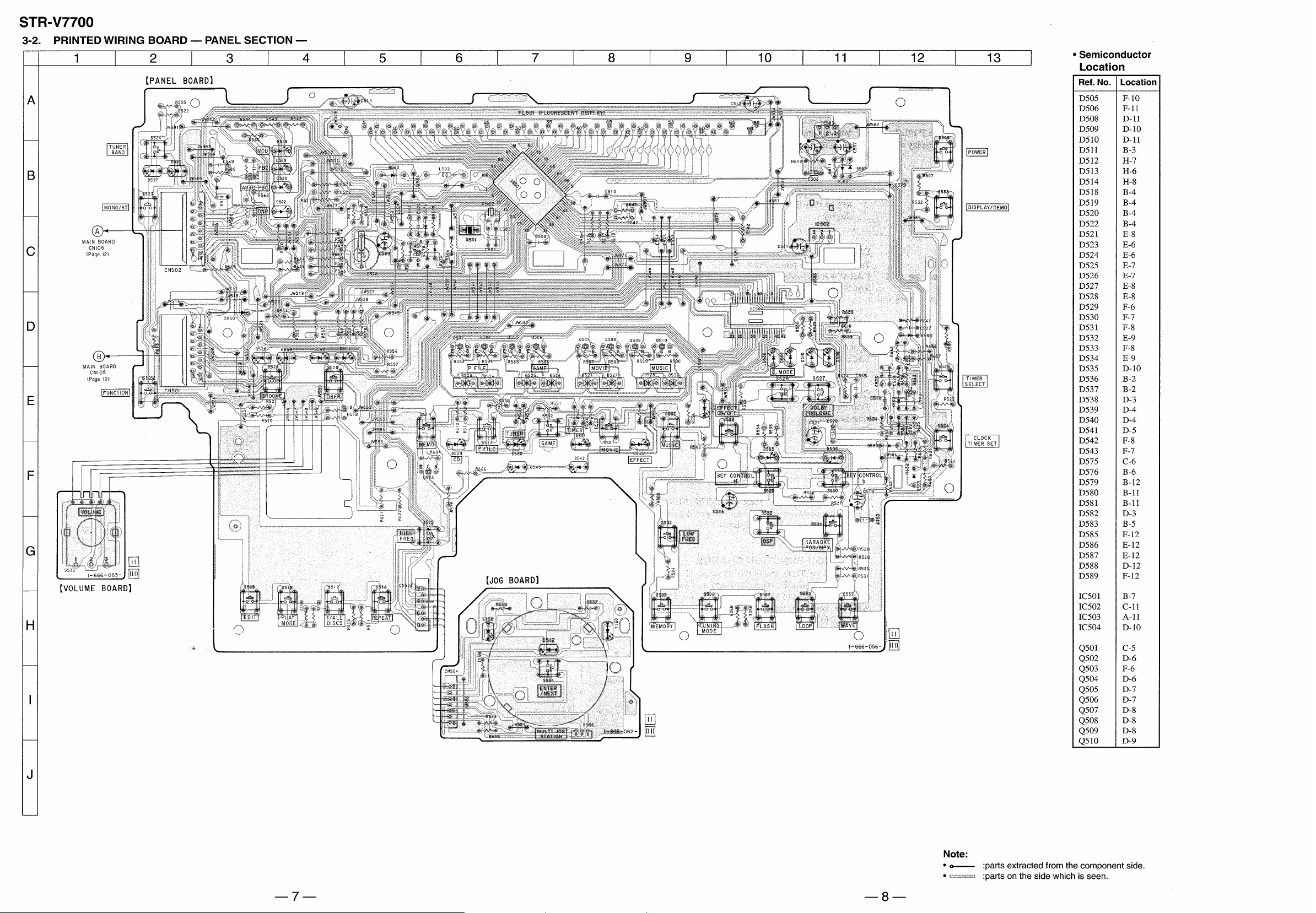
3-2. Printed Wiring Board — Panel Section —·························7
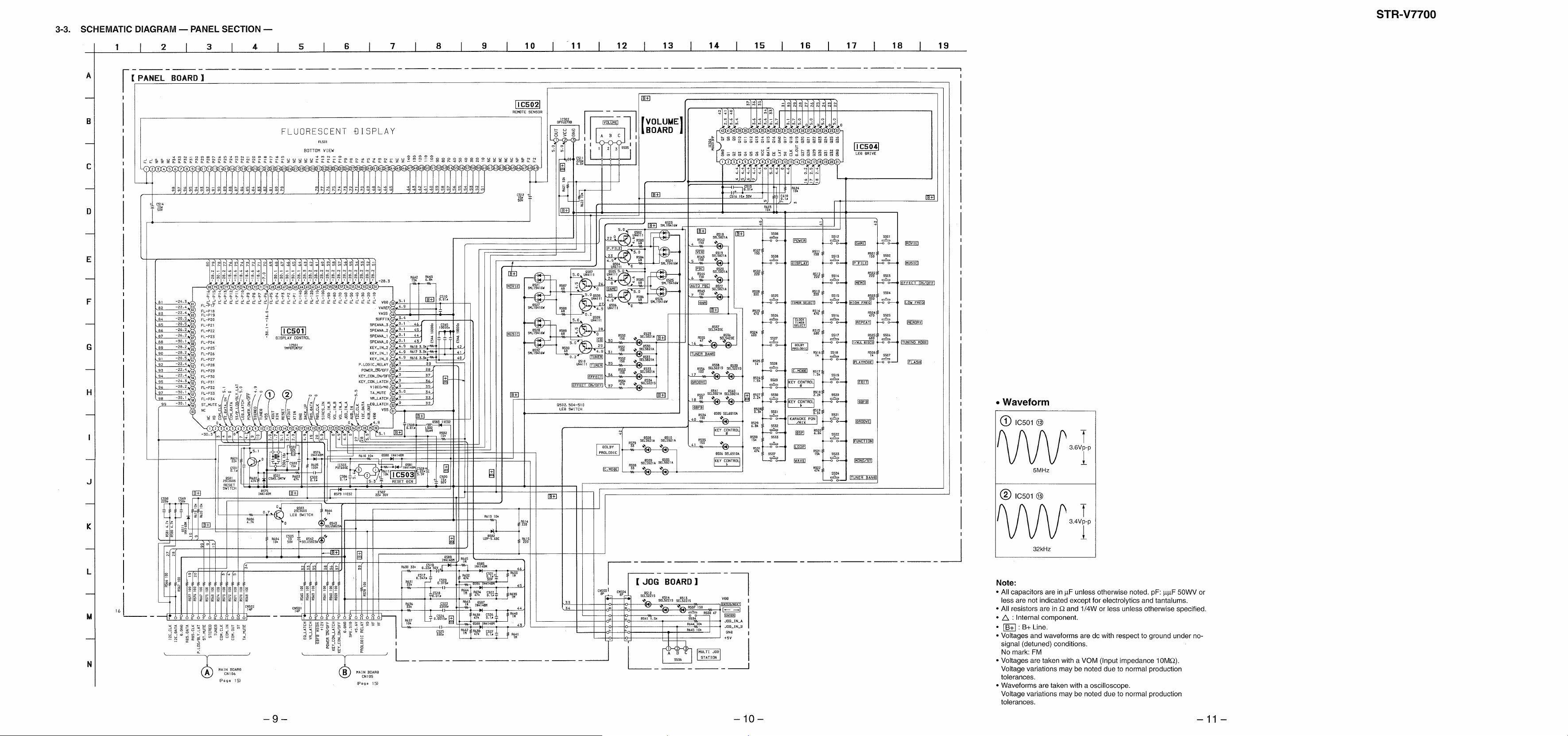
3-3. Schematic Diagram — Panel Section — ··························· 9
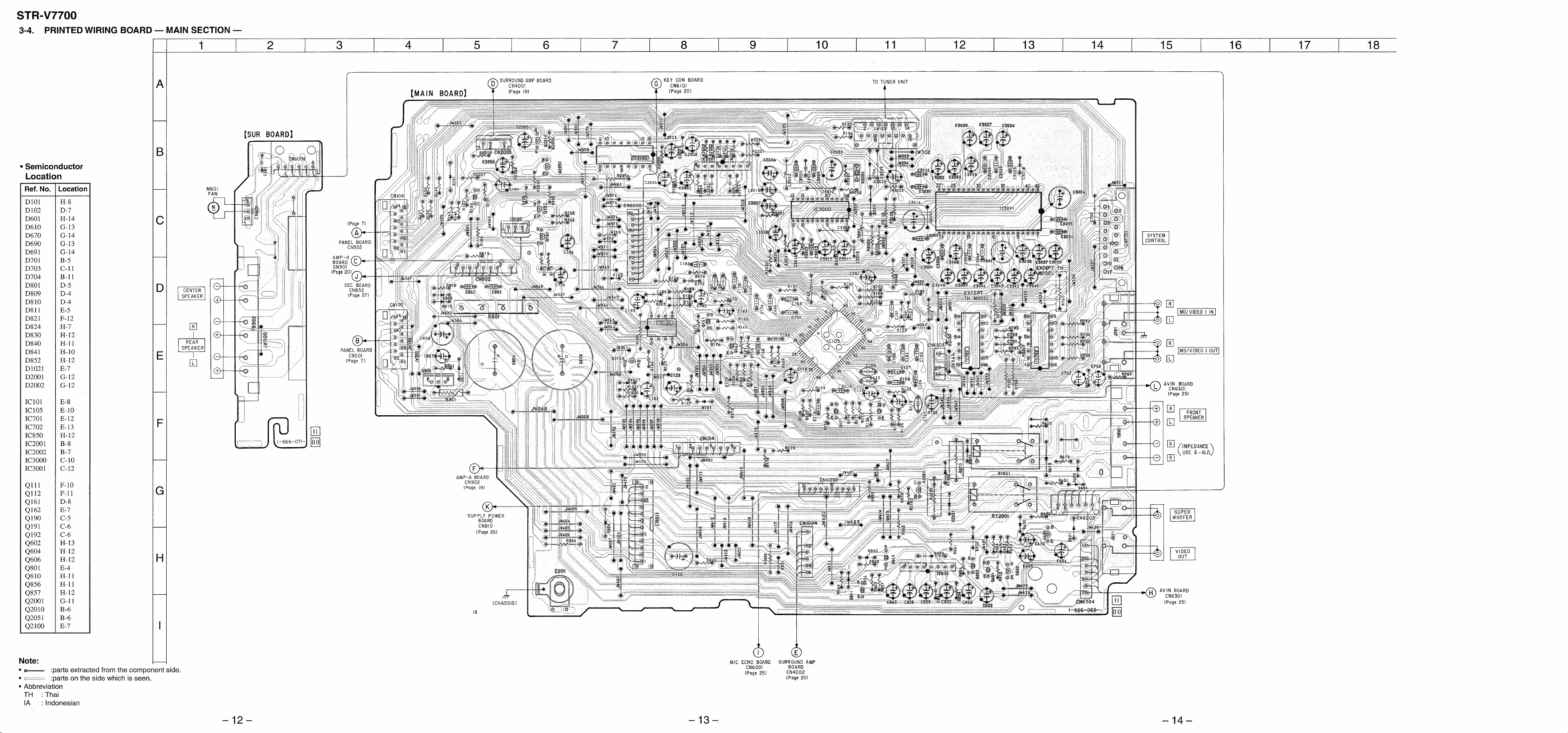
3-4. Printed Wiring Board — Main Section — ······················· 12
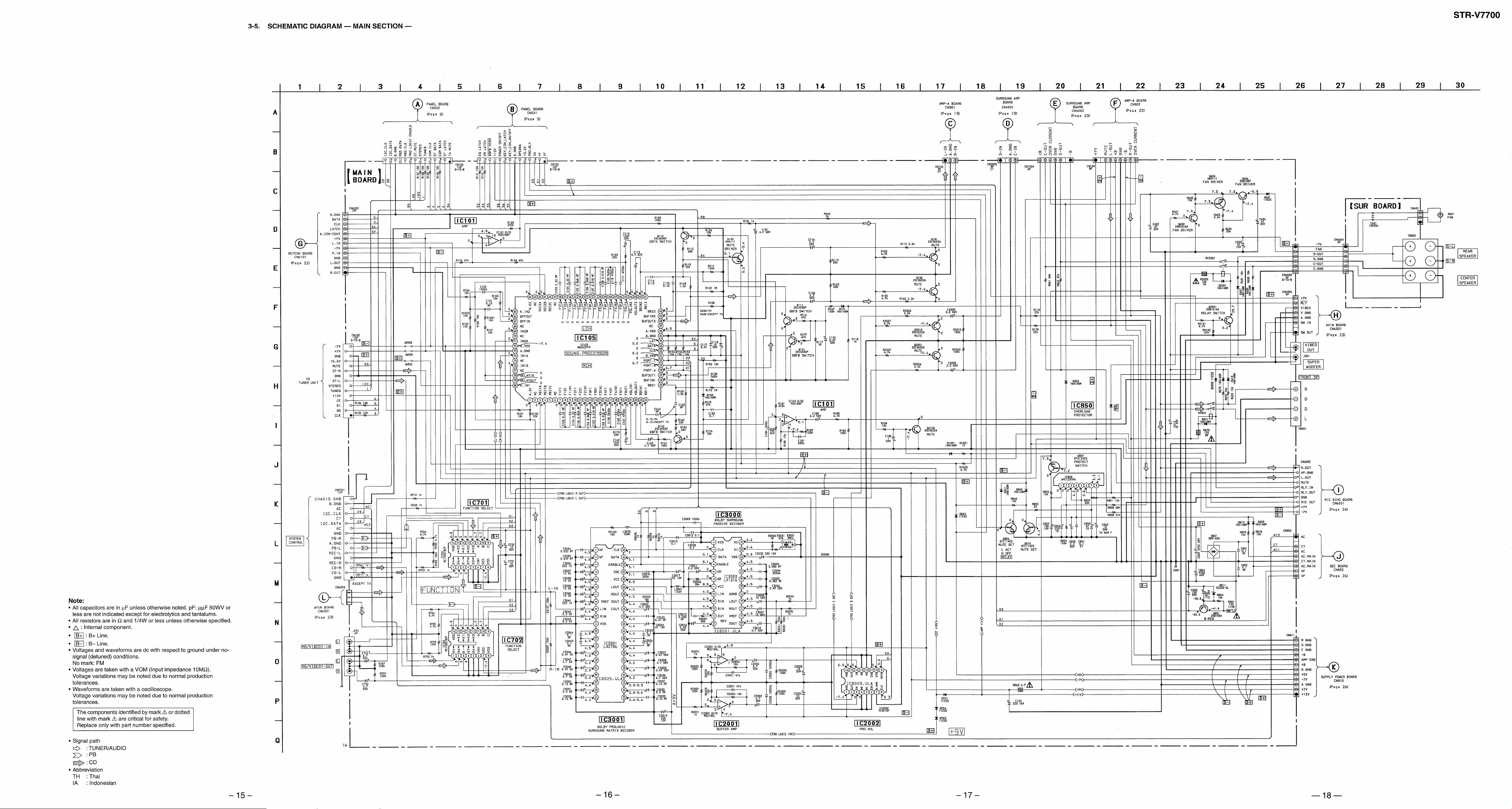
3-5. Schematic Diagram — Main Section — ·························· 15
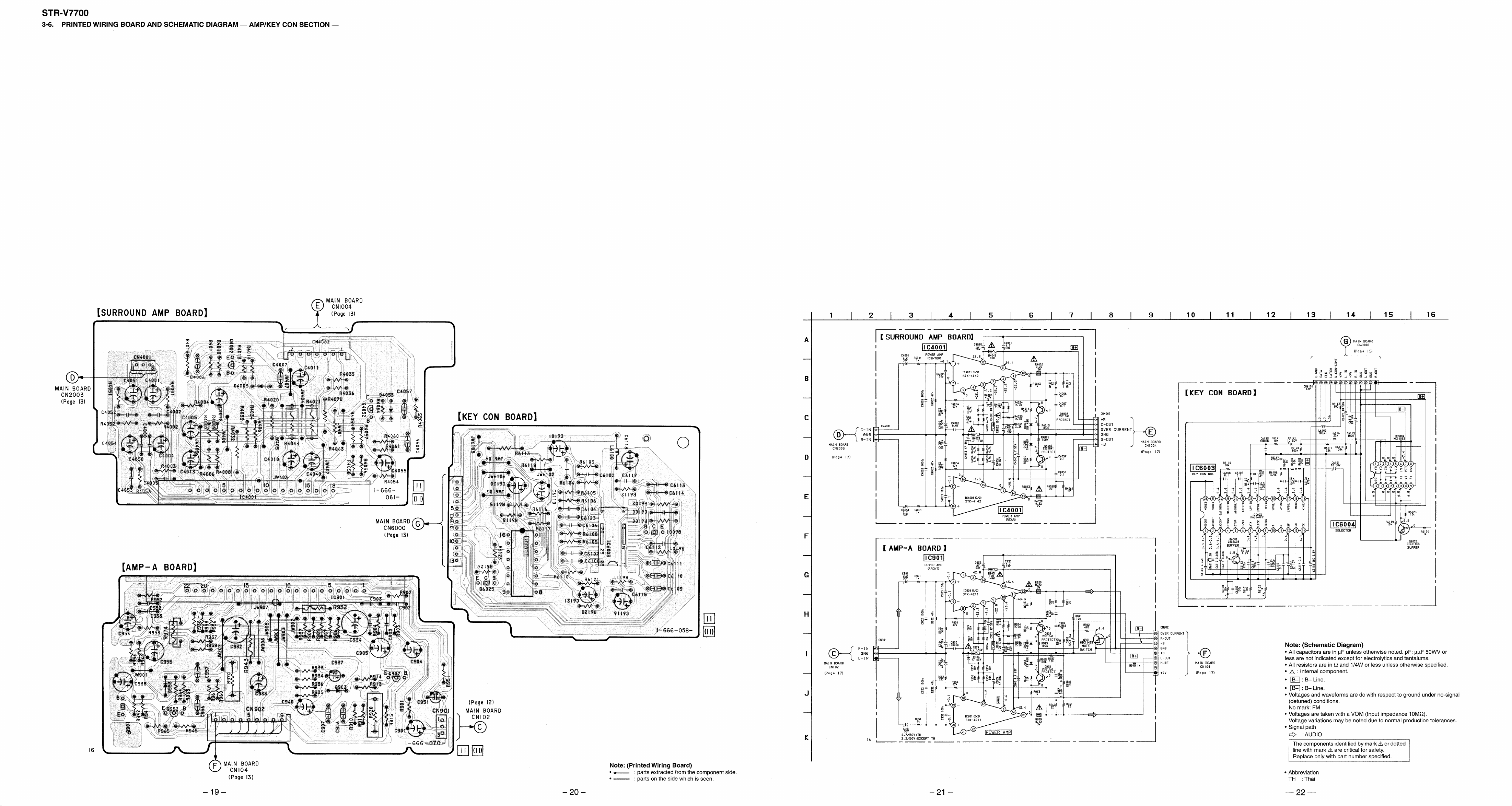
3-6. Printed Wiring Board and Schematic Diagram
— Amp/Key con Section —············································ 19
3-7. Printed Wiring Board and Schematic Diagram
— Mic Echo/AV in Section — ········································ 23
3-8. Printed Wiring Board and Schematic Diagram
— Power Section —························································26
3-9. IC Pin Function ································································ 29
3-10. IC Block Diagrams ··························································· 31
4. EXPLODED VIEWS
4-1. Main Section····································································· 33
4-2. Panel Section ···································································· 34
5. ELECTRICAL PARTS LIST ··································· 35
SAFETY-RELATED COMPONENT WARNING!!
COMPONENTS IDENTIFIED BY MARK ! OR DOTTED LINE WITH
MARK ! ON THE SCHEMATIC DIAGRAMS AND IN THE PARTS
LIST ARE CRITICAL TO SAFE OPERATION. REPLACE THESE
COMPONENTS WITH SONY PARTS WHOSE PART NUMBERS
APPEAR AS SHOWN IN THIS MANUAL OR IN SUPPLEMENTS
PUBLISHED BY SONY .
Notes on chip component replacement
• Never reuse a disconnected chip component.
• Notice that the minus side of a tentalum capacitor may be damaged
by heat.
— 2 —
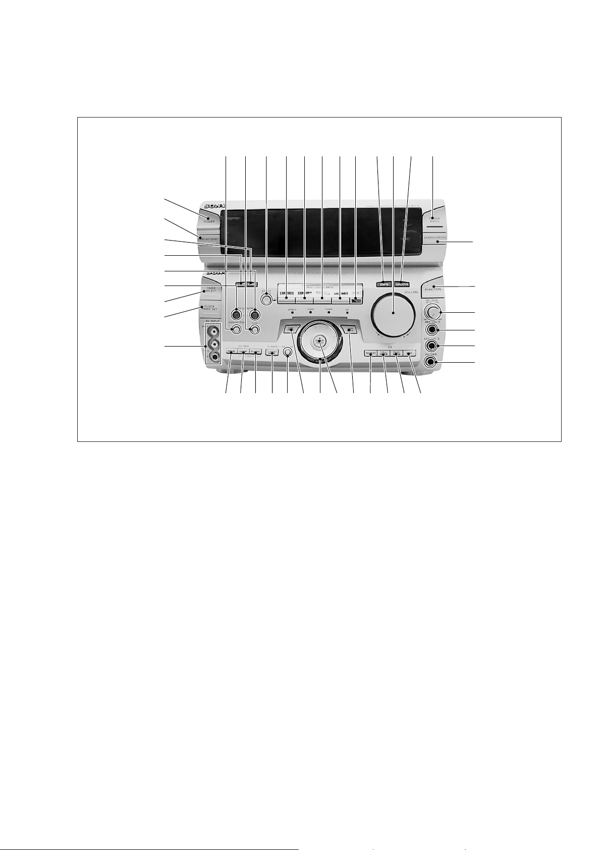
— FRONT PANEL —
SECTION 1
GENERAL
12345678 9!º!¡ !™
$º
#ª
#•
#¶
#§
#∞
#¢
#£
#™
1 KARAOKE PON/MPX button
2 DSP button
3 EFFECT ON/OFF button
4 MUSIC button
5 MOVIE button
6 GAME button
7 P FILE button
8 MEMO button
9 DBFB button
!º VOLUME
!¡ GROOVE button
!™ TUNER BAND button
!£ STEREO/MONO button
!¢ FUNCTION button
!∞ MIC LEVEL/ECHO VOL
!§ MIX MIC 1 jack
!¶ MIX MIC 2 jack
!• PHONES jack
!ª EDIT button
@º PLAY MODE button
#¡
!£
!¢
!∞
!§
!¶
!•
!ª@º@¡@™@£@¢@¶ @∞@§@•@ª#º
@¡ 1/ALL DISCS button
@™ REPEAT button
@£ HIGH FREQ button
@¢ ENTER/NEXT button
@∞ MULTI JOG STATION dial
@§ LOW FREQ button
@¶ MEMORY button
@• TUNING MODE button
@ª FLASH button
#º LOOP button
#¡ WAVE button
#™ AV INPUT jack
#£ CLOCK TIMER SET button
#¢ TIMER SELECT button
#∞ KEY CONTROL ˜ button
#§ KEY CONTROL n button
#¶ DOLBY PROLOGIC button
#• C. MODE button
#ª DISPLAY/DEMO button
$º POWER button
— 3 —
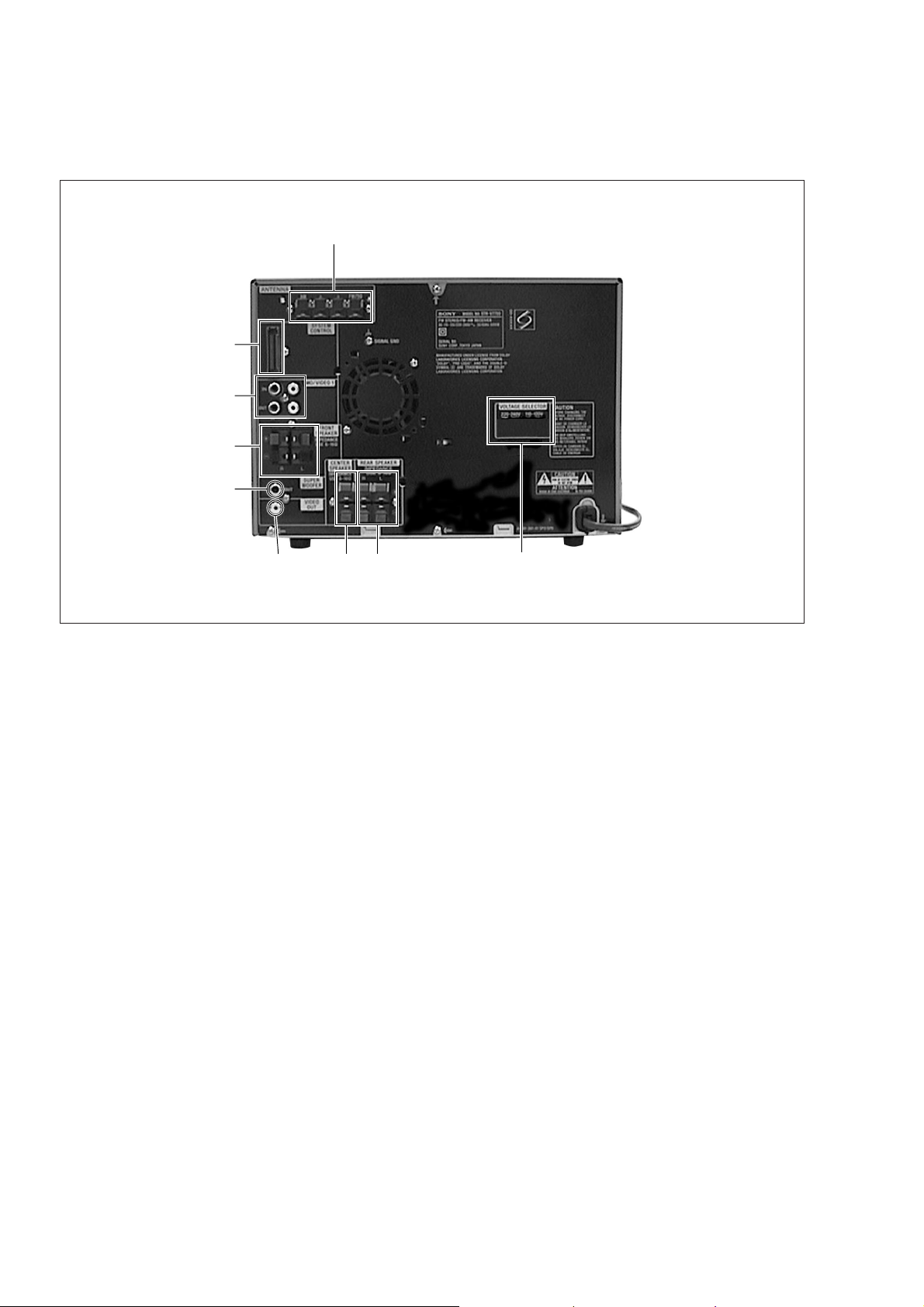
— BACK PANEL —
$ª
$¡
$™
$£
$¢
$∞
$§ $¶
$•
$¡ SYSTEM CONTROL
$™ MD/VIDEO 1 jack
$£ FRONT SPEAKER terminal
$¢ SUPER WOOFER jack
$∞ VIDEO OUT jack
$§ CENTER SPEAKER terminal
$¶ REAR SPEAKER terminal
$• VOLTAGE SELECTOR switch (EXCEPT TH, KR)
$ª ANTENNA terminal
• Abbreviation
TH : Thai
KR : Korean
— 4 —
SECTION 2
TEST MODE
FL DISPLAY/KEY LED TEST MODE
Press the REPEAT, ENTER/NEXT and SURROUND buttons
simultaneously.
1. All FL segments and all LEDs turn on.
2. To access the microprocessor information, press the P FILE
key. Each pressing of the P FILE key adv ances the display on
the FL tube in the following sequence.
STR microprocessor version number
HCD microprocessor version number
VCD microprocessor version number (VCD model only)
Model name
Destination
3. To check the encoder , press the MUSIC key . The follo wing display
appears on the FL tube.
"K0J0V0"
The number after K indicates the number of times that the key is
pressed. The key which was pressed in the past, is not counted.
The key which is pressed hereafter is counted. Pressing any key
increases the number after K.
The number after J indicates the number of rotations that the JOG
dial is rotated. Turning the JOG dial clockwise increases the number
after J. Turning the JOG dial counter-clockwise decreases the
number after J.
The number after V indicates the number of rotations that the
VOLUME dial is rotated. Turning the VOLUME dial clockwise
increases the number after V. Turning the VOLUME dial counterclockwise decreases the number after V.
To exit this mode, perform the "Cold Reset" (reset clearing memory)
as described below.
GENERAL TEST MODE
(INCLUDING AMPLIFIER AND TUNER)
Press the REPEAT, ENTER/NEXT and CLOCK TIMER SET
buttons simultaneously while the main power is on.
1. Sound volume display segment starts blinking.
2. The tuning enters the PRESET mode.
3. Rotating the VOLUME control clockwise increases the volume
level to maximum.
Rotating the VOLUME control counter-clockwise decreases
the volume level to minimum.
4. Pressing the MUSIC key decreases the equalizer curve to
minimum and "EQ CHECK" appears on the display.
Pressing the MOVIE key increases the equalizer curve to
maximum.
Pressing the GAME key makes the equalizer curve flat.
5. Pressing any of the DBFB, GROOVE or SURROUND key
disappears "EQ CHECK" on the display.
To exit this mode, perform the "Cold Reset" (reset clearing memory)
as described below.
AGING MODE
1. CD aging mode
To execute the CD aging, set the three discs to the CD tray and
set the function to CD. REPEAT, ENTER/NEXT and LOOP
buttons simultaneously. The CD aging mode starts and the disc
calendar starts blinking.
2. Tape aging mode
To execute the tape aging, set the two tapes to the tape A and B
drives. Set the function to T APE. Press the REPEA T , ENTER/
NEXT and LOOP buttons simultaneously. Press the A forward
key to start the tape aging mode. "AGING" appears on the
display.
CD SERVICE MODE
Turn on the main power. Press the REPEAT, ENTER/NEXT and
KARAOKE PON/MPX buttons simultaneously.
VACS toggles between ON and OFF.
VACS LEVEL DISPLAY
Turn on the main power. Press the EDIT, ENTER/NEXT and
KARAOKE PON/MPX buttons simultaneously.
VACS level appears on the display.
CD SHIP MODE
Turn on the main power. Press the PLAY MODE and POWER
buttons simultaneously.
The main power is turned off and LOCK appears on the display.
TUNER STEP CHANGE
Turn on the main power. Set the function to TUNER. Select MW
band from the present tuning.
Turn off the main power. Press the ENTER/NEXT and POWER
buttons simultaneously. The main power is turned on and the
changed step appears on the display.
MD/VIDEO 1 FUNCTION CHANGE
Press the FUNCTION and POWER buttons simultaneously while
the main power is off. When the function is set to VIDEO 1, the
function is changed to MD and MD appears on the display.
When the function is set to MD, the function is changed to VIDEO
1 and VIDEO 1 appears on the display.
COLD RESET (Reset which clears memory.)
Press the REPEAT, ENTER/NEXT and DISPLAY buttons
simultaneously at any time. The system is reset while clearing
memory.
HOT RESET
(Reset which does not clear memory.)
Press the REPEAT, ENTER/NEXT and TIMER SELECT buttons
simultaneously at any time. The system is reset without clearing
memory.
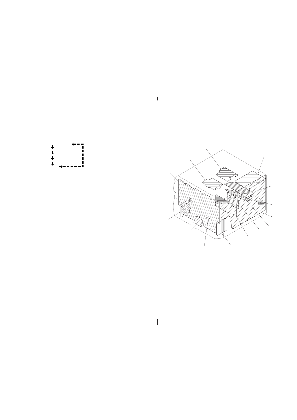
3-1. CIRCUIT BOARDS LOCATION
SEC BOARD
PANEL BOARD
AVIN BOARD
JOG BOARD
VOLUME BOARD
PRI BOARD
SECTION 3
DIAGRAMS
MIC ECHO BOARD
ENCAPSULATED
COMPONENT
KEY-CON BOARD
SUPPLY POWER BOARD
AMP-A BOARD
SUR BOARD
MAIN BOARD
SURROUND
AMP BOARD
— 5 — — 6 —
 Loading...