

FM Stereo
FM.AM Receiver
4-230-063-12(1)
Operating Instructions
STR-V555ES
,:_,2000 Sony Corporation
WARNING Precautions
To prevent fire or shock
hazard, do not expose the
unit to rain or moisture.
For customers in the United States
CAVlIONTOR_OUC_1_ _IS__ E_C_RICS_IOCa
This symbol is intended to alert the user to the
presence of uninsulated dangerous voltage"
within the product's enclosure that may be of
sufficient magnitude to constitute a risk of
electric shock to persons.
This symbol is intended to alert the user to
the presence of important operating and
maintenance (servicing) instructions in the
literature accompanying the appliance.
INFORMATION
This equipment has been tested and found to
comply with the limits for a Class B digital
device, pursuant to Part 15 of the FCC Rules.
These limits are designed to provide
reasonable protection against harmful
interference in a residential installation.
This equipment generates, uses, and can
radiate radio fl equency energy and, if not
installed and used in accordance with the
instructions, may cause harmf_fl
interference to radio commtmications.
However, there is no guarantee that
interference will not occur in a particular
installation. If this equipment does cause
harmfifl interference to radio or television
reception, which can be determined by
turning the equipment off and on. the user
is encouraged to try to correct the
interference by one or more of the
following measures:
Reorient or relocate the receiving
antenna.
Increase the separation hetween the
equipment and receiver:
Connect the equipment into an outlet on
a circuit different fi'om that to which the
receiver is connected.
Consult the dealer or an experienced
radio/TV technician fbr help.
2
CAUTION
You are eautioned that any ehanges or
modification not expressly approved in
this manual cotfld void your authority to
operate this equipment.
Note to CAW system installer:
This reminder is provided to call CATV
system installer's attention to Article 820
40 of the NEC that provides guidelines for
proper grotmding and, in particular.
specifies that the cable grotmd shall be
connected to the grounding system of the
huilding, as close to the point of cable
entry as practical.
Owner's Record
The model and serial numbers are ]oeated
on the rear of the trait. Record the serial
number in the space provided helow.
ReDr to them whenever you call upon
your Sony dealer regarding this product.
Model No. STR V555ES
Serial No.
ENERGY STAR' is a U.S. registered mark.
As an ENERGY STAR" partner; Sony
Corporation has determined that this
product meets the ENERGY STAR"
guidelines fur energy eftMency.
Forcustomers in Canada
CAUTION
TO PREVENT ELECTRIC;SHOCK, DO
NOT USE THIS POLARIZED AC PLUG
WITH AN EXTENSION CORD,
RECEPTACLE OR OTHER OUTLET
UNLESS THE BLADES CAN BE FULLY
INSERTED TO PREVENT BLADE
EXPOSIIRE.
Forcustomersin Europe
To avoid electrical shock, do not
open the cabinet. Refer
servicing to qualified personnel
only.
Do not install the appliance in a
confined space, such as a
bookcase or built-in cabinet.
A_46
On safety
Should any solid objeet or liquid fell into
the cabinet, unl)lug the receiver and have it
checked by qualified personnel hefore
operating it any fiwther.
On power sources
• Befbre operating the reeeiver, cheek that
the operating voltage is identical with
your local power supply. The operating
voltage is indicated on the nameplate at
the rear of the receiver.
• The trait isnot disconnected flora the AC
power somce (mains) as long as it is
connected to the wall outlet, even ifthe
trait itself has been turned off.
• If you are not going to use the receiver
for a long time, be stne to disconnect the
receiver fl'om the wall outlet. To
disconnect the AC power cord, grasp the
plug itself; never pull the cord.
• One blade of the plug is wider than the
other fur the propose of safety and will
fit into the wall outlet only one way. If
you are tmable to insert the plug f\flly
into the outlet, contact your dealer.
• AC power cord nmst be changed only at
the qualified service shop.
On placement
• Plaee the reeeiver in a ]oeation with
adequate ventilation to prevent heat
htfildup and prolong the life of the
receiver.
• Do not place the receiver near heat
sources, or in a place subject to direct
sunlight, excessive dust or mechanical
shock.
• Do not place anything on top of the
cabinet that might block the ventilation
holes and cause malfunctions.
On operation
Before eonneeting other eomponents_ be
sure to tmn off and unplug the receiver.
On cleaning
Clean the eabinet, panel and eontrols with
a sot cloth slightly moistened with a mild
detergent solution. Do not use any type of
abrasive pad, scouring powder or solvent
such as alcohol or benzine.
If you have any question or problem
concerning your receiver, please
consult your nearest Sony dealer.
About This Manual TABLE OF CONTENTS
About area codes
The area rode of the rereiver you purrhased is shown on
the lower portion of the rear panel (see tile illustration
below).
_ 4-XXX-XXX-XX AA
-_- Area code
Any differences in operation, arrording to tile area rode, are
clearly indicated in tile text, fbr example, "Models of area
code AA only".
Conventions
• The instructions in this manual describe the controls on
the receiver. You can also use the controls on the
supplied remote if they have the same or similar names
as those on the receiver. For details on the use of your
remote, ref>r to the separate operating instructions
supplied with the remote.
• The tbllowing icon is used in this manual:
"_"Indicates hints and tips for making the task
easier.
This receiver incorporates Dolhy* Digital and Pro Logic
Surround and the DTS**Digital Surrotmd System.
* ManufacturedunderJicenseh'omDollzvLaboratories.
"Dolby" "AC 3" "ProLogic"and fl_edoubleD s_m]bolEll:]are
rrademarksofDoJbyLaboratories.
Confidenria!unpublishedWbrks.co"!002 !997DoJbvLaboratories.
AJIrights reserved.
**Manufi_cturedunder licensefi'omDigital TheaterSv:stems h]c. US
Pag No. 5,451,942 and other u'oIMu'idepatents issued and pending
"DTS" and "DTS Digitai Sun'ound" are trademarks of Digital
TheaterSv:stems,Inc. co!996 Digital Theater Swtems, Inc.A11
rights reserved.
Hooking Up the Components 4
Unpacking 4
Antenna Hookups 5
Audio Component Hookups 6
Video Component Hookups 7
Digital Component Hookups 8
5,1CH Input Hookups 10
Other Hookups 11
HookingUpand Setting Up the
Speaker System 14
Speaker System Hookup 15
Performing Initial Setup Operations 17
Multi Channel Surround Setup 18
Before You Use Your Receiver 23
i!!!!!!!!!!!!!!!!!!_!!!!!!!!!!!!!!!!!!!!!!!!!!!!!!!!::iii__ _(!................................................................................................{ii
Location of Parts and Basic
Operations 24
Front Panel Parts Description 24
Enjoying Surround Sound 29
Selecting a Sound Field 30
Understanding the Multi-Channel Surround
Displays 35
Customizing Sound Fields 36
Receiving Broadcasts 45
Storing FM Stations Automatically
(AUTOBETICAL)*** 46
Direct Tuning 47
Automatic Tuning 47
Preset Tuning 48
Using the Radio Data System (RDS)*** 49
***Models ot areacodeCED olll)t
Other Operations 52
Naming Preset Stations and Program Sources 53
Recording 53
Using the Sleep Timer 54
Adjustments Using the SET UP Button 55
CONTROLAln Control System 57
__[!
Additional Information 59
Troubleshooting 59
Specifications 61
Glossary 64
Tables of Settings Using SURROUND, LEVEL, EQ,
and SET UP buttons 65
Index (Back cover)
3
Unpacking
Check that you received the following items with the unit:
• FMwire antenna (1)
• AM loop antenna (1)
• Remote commander RM-TP504 (remote) (1)
• LR(;(size-AA) alkaline batteries (4)
• Coin shaped lithium battery (CR-2032) (1)
Models of area code UC only
• Audio/video/control S connecting cord (1)
• Control S connecting cord (1)
• Remote commander RM-US104 (remote) (1)
• R6 (size-AA) batteries (2)
Insert batteries with the + and properly oriented in the
battery compartment. When using tile remote, point it at
the remote sensor _ on tile receiver
For details, refer to the operating instructions supplied
with your remote.
"_" Whento replace batteries
Under normal conditions, the batteries should last for about
3 months. When tbe remote no longer operates the receivei;
replace all batteries with new ones.
Notes
• Do not leave the remote in an extremely hot or humid place.
• Do not use a new batteW with an old one.
• Do not expose the remote sensor to direct stmlight or lighting
apparatuses. Doing so may cause a mall\ruction.
• Ifyou don't use the remote fur an extended period of time,
remove the batteries to avoid possible damage fl'om battery
leakage and corrosion.
• The remote RM TP504 is designed fur use with alkaline
batteries only. Do not use a combination of difterent battery
types.
• Turn off the power to all coinponents [)eft)re making
any connections.
• Do not connect the AC power cord until all of the
connections are coinpleted.
• Be sure to make connections firnfly to avoid hum and
noise.
• When connecting an audio/video cord, be sure to
match the color-coded pins to the appropriate jacks on
the components: yellow (video) to yellow; white (lefL
audio) to white; and red (right, audio) to red.
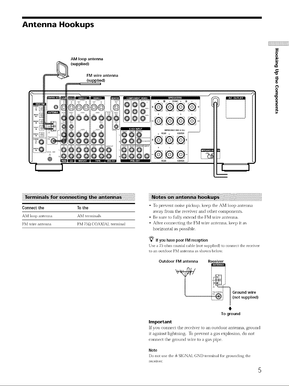
Antenna Hookups
AM loop antenna
(supplied)
FM wire antenna
(supplied)
--@@@@-
IMPEDANCEUSE 4-16_ --
-F_ _ _iIr REAR L CENTER
@ @
REAR
"0
0
0
5'
e-
O
O
3
O
(D
Connectthe
AM loop antenna
FM wire ai'_tenna
To the
AM terminals
FM 75f_ COAXIAL terminal
• Toprevent noise pickup, keet) the AM loop antenna
away from the receiver and other components.
• Be sure to tkfllyextend the FM wire antenna.
• After connecting the FM wire antenna, keep it as
horizontal as possible.
"_W"If you have poor FM reception
F.
Use a 7a Ol'lIl-icoaxial cable (not supplied) to coTmect the receiver
to an outdoor FM antenna as shown below.
Outdoor FM antenna
Y
Important
If you connect the receiver to an outdoor antenna, ground
it against lighming. To prevent a gas explosion, do not
connect the ground wire to a gas pipe.
Receiver
7_°°_'×'_ Ground wire
(not supplied)
To ground
Note
Do not use the rb SIGNAL GND termh_a] for grounding the
receiver.
5
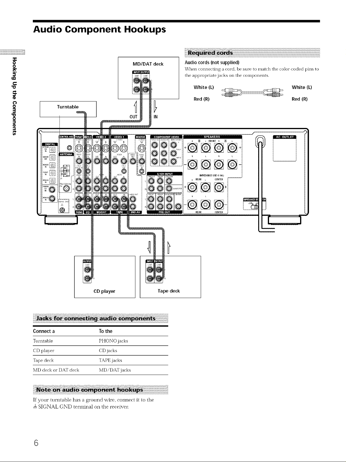
Audio Component Hookups
"T-
O
O
MDIDAT deck
5'
c
"o
e_
¢
O
O
g
"o
0
Turntable
OUT IN
Audio cords (not supplied)
_Vhen connecting a cord, be sure to match the color coded pins to
the appropriate jacks Oil tile components.
White (L) White (L)
Red (R) Red (R)
CD player
Connect a To the
Turntable PHONO jacks
CD player CD jacks
Tape deck TAPE jacks
MD deck or DAT deck MD/DAT jacks
If your turntable has a ground wire, connect it to the
SIGNAL GND terminal on the receiver.
6
Tape deck
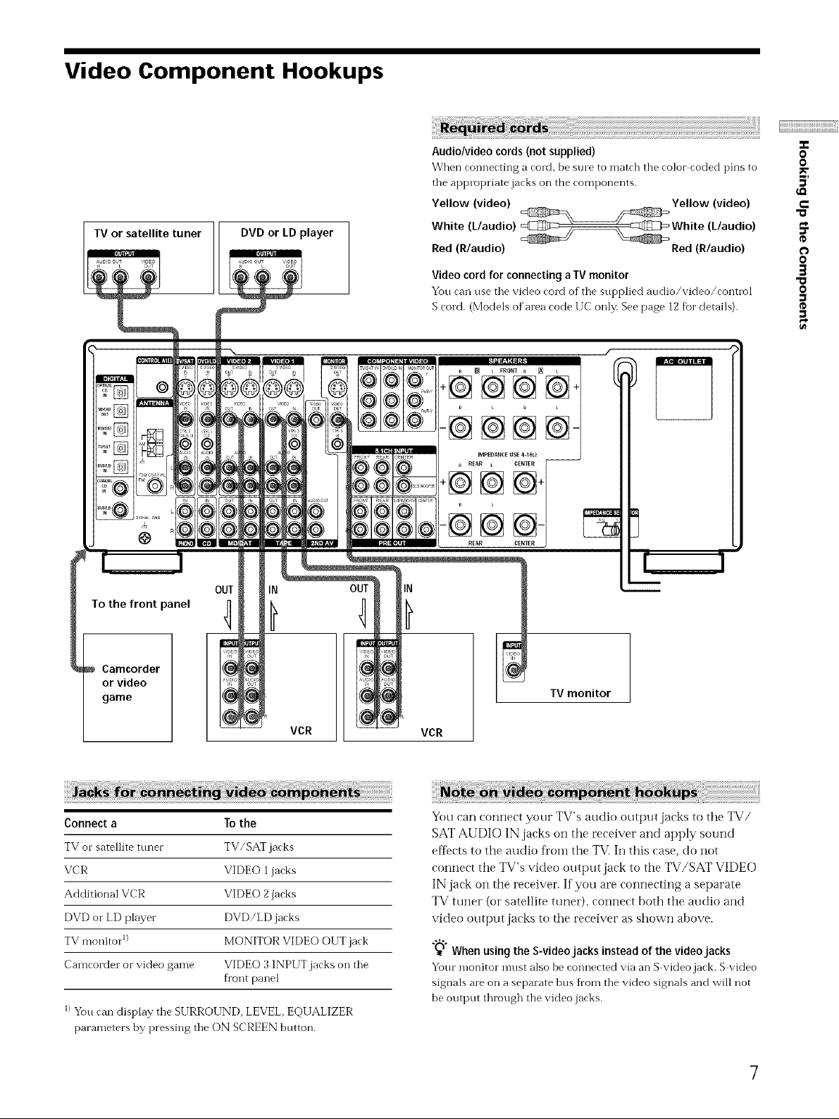
Video Component Hookups
TV or satellite tuner DVD or LD player
i ¸¸¸¸¸
Audio/video cords (not supplied)
When connecting a cord, be sine to match the color coded pins to
tile appropriate jacks oil the components.
Yellow (video) Yellow (video)
White (L/audio) White (L/audio)
Red (R/audio) Red (R/audio)
Video cord for connecting a IV monitor
You can use tile video cord of the supplied audio/video/control
S cord. (Models of area code IIC only. See page 12 for details).
_ L FRONT R [] L
÷@@@@+
-@@@@-
-T-
O
0
5'
e-
"a
O
O
3
0
OUT
To the front panel r]
Camcorder
or video
game
Connect a To the
TV or satellite tuner TV/SAT jacks
VCR VIDEO 1 jacks
Additional VCR VIDEO 2 jacks
DVD or LD player DVD/LD jacks
TV monitor 1) MONITOR VIDEO OUT jack
Camcorder or video game VIDEO 3INPUT jacks on the
fl'ont panel
IN
VCR
I)Yon can display the SURROUND, LEVEL,EQUALIZER
parameters by pressing the ON SCREEN button.
IN
TV monitor
VCR
You can connect your TV's audio output jacks to the TV/
SAT AUDIO IN jacks on the receiver and apply sound
effects to the audio fl'om the TVi In this case, do not
connect the TV's video output jack to the TV/SAT VIDE(-)
IN jack on the receiver. If you are connecting a separate
TV tuner (or satellite tuner), connect both the audio and
video output jacks to the receiver as shown above.
_'° When using the S-videojacks instead of the video jacks
Your monitor mnst also be connected via an S video jack. S video
signals ale on a separate bus fl'om the video signals and will not
be output through the video jacks.
7
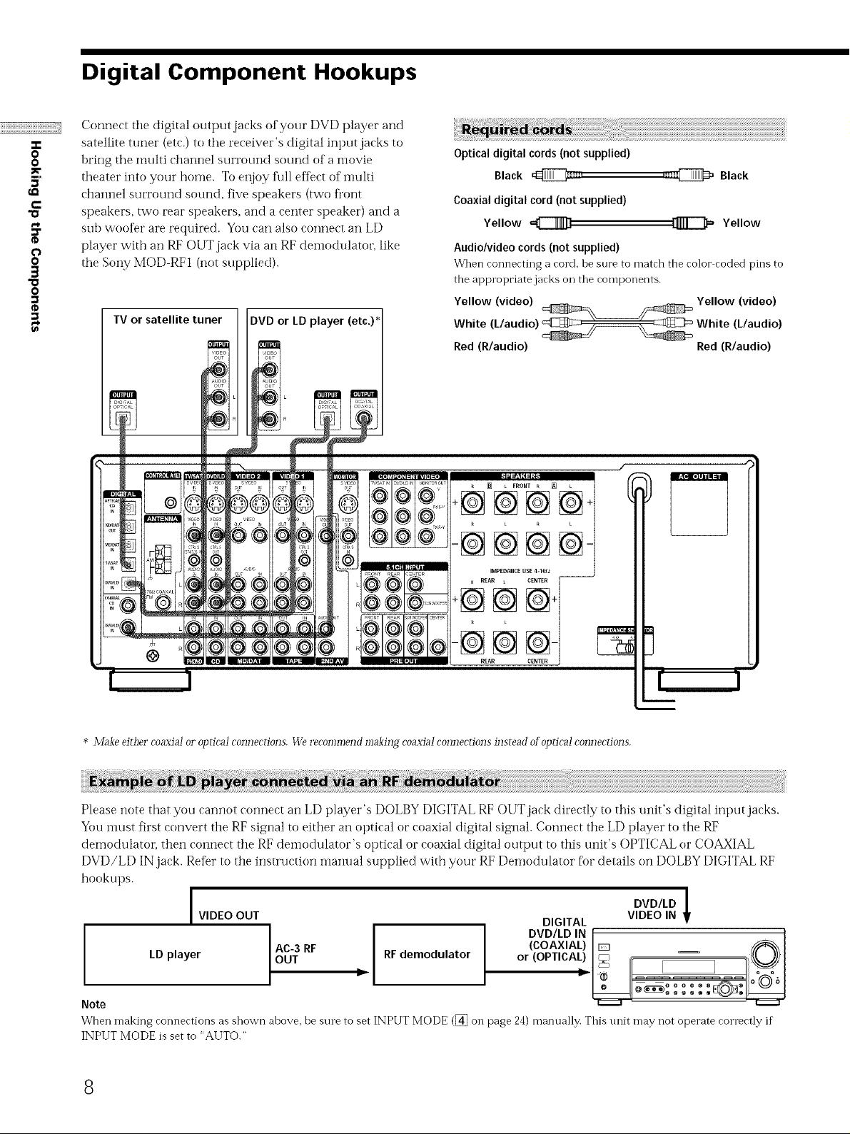
Digital Component Hookups
Connect the digital output jacks of your DVD player and
.p
0
0
5'
c
"o
p_
¢
O
0
g
O
$,
satellite tuner (etc.) t@the receiver's digital input jacks to
bring the multi channel surround souiKt @fa i'flovie
theater into your home. To enjoy fifll eft_ct of multi
channel surround sound, five speakers (two ti'@nt
speakers, two rear speakers, and a center speaker) and a
sub woofer are required. You can also connect an LD
player with an RF OUT jack via an RF dem@dulato_; like
the Sony MOD RFI (not supplied).
TV or satellite tuner DVD or LD player (etc.)*
Optical digital cords (not supplied)
Black @i_,
Coaxial digital cord (not supplied)
Yellow
Audio/video cords (not supplied)
When connecting a cord, be sure to match the color coded pins to
the appropriate jacks on the components.
Yellow (video) Yellow (video)
White (L/audio) @_/__ White (L/audio)
Red (R/audio) Red (R/audio)
_ L FRONT R [] t
,_i@ Black
Yellow
-@@@@
@
* Make either coaxiaJ oi"opdcaJ connections. We recommend making coaxiai connections instead olopdcaJ connections.
Please note that you cannot connect an LD player's DOLBY DIGITAL RF OUT jack directly to this unit's digital input jacks.
Yotl must first convert the RF signal to either an optical or coaxial digital signal. Connect the LD player to the RF
demodulator, then connect the RF demodulator's optical or coaxial digital output to this unit's OPTICAL or COAXIAL
DVD/LD IN jack. Refer to the instruction manual supplied with your RF Demodulator fi_r details on DOLBY DIGITAL RF
hookups.
I DVD/LD
VIDEO OUT DIGITAL VIDEO IN
LD player I RF RF demodulator
,ou, C °
Note
When making connections as shown above, be sure to set INPUT MODE (_ on page 24) manually. This unit may not operate correctly if
INPUT MODE is set to "AUTO."
, ;
8
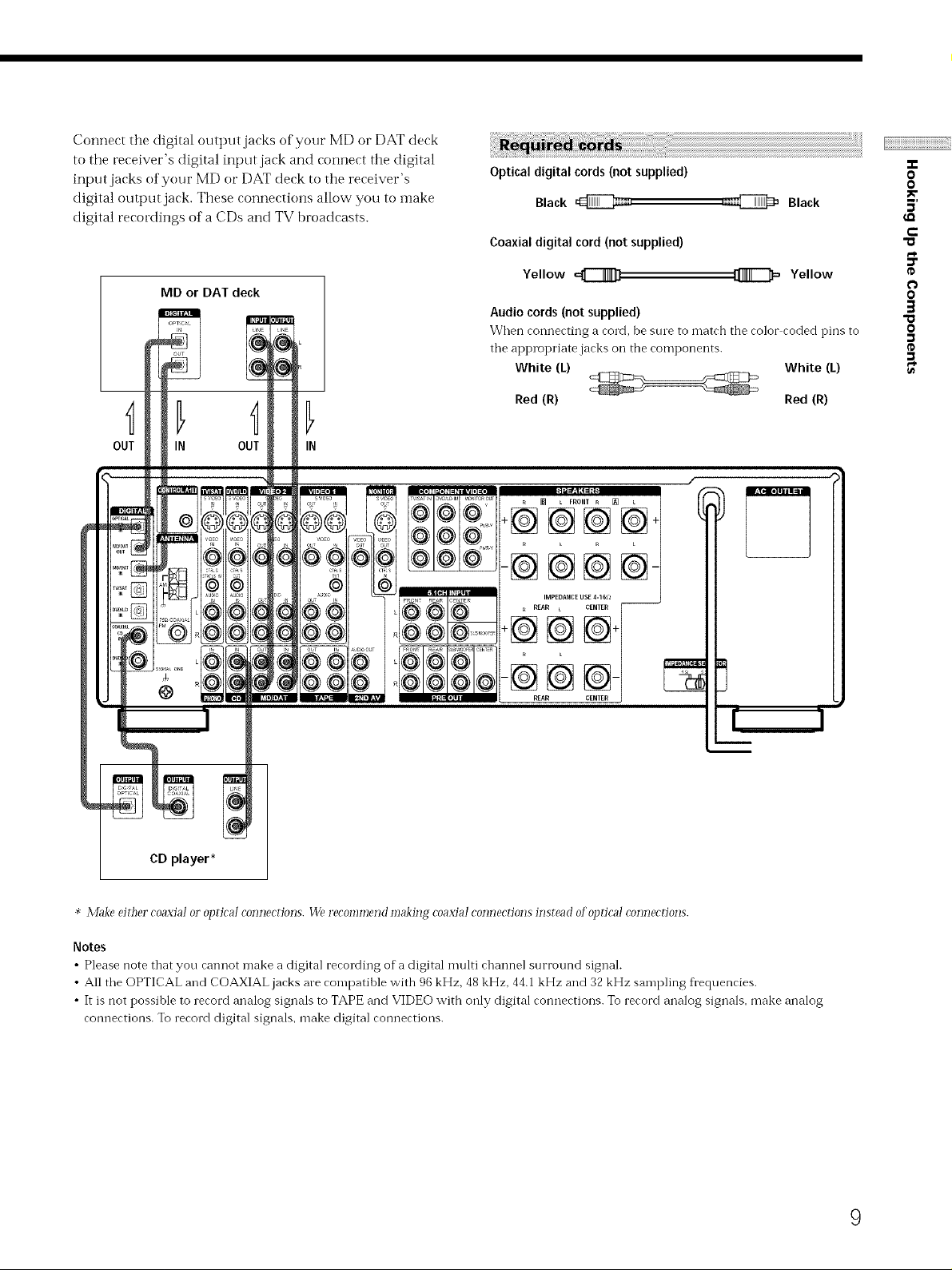
Connect the digital outt)ut jacks of your MD or DAT deck
to the receiver's digital input jack and connect the digital
input jacks of your MD or DAT deck to the receiver's
digital output jack. These connections allow you to make
digital recordings of a CDs and TV broadcasts.
Optical digital cords (not supplied)
Black _=,
Coaxial digital cord (not supplied)
,a_ Black
0
0
MD or DAT deck
Yellow '=C_[]
Audio cords(notsupplied)
When connecting a cord, be sine to match the color coded pins to
0
0
"o
O
the appropriate jacks on the components.
White (k) White (/)
Red (R) Red (R)
IN
_ L FRONT R [] L
+@@@@
-@@@@
IMPEDANCE USE 4-16_ --
REAR L CENTER
-@@
REAR
CD player*
* Make either coaxia! or optica! com]ecdons. We recommend making coaxial connections instead ofol)tical connections.
Notes
• Please note that you cannot make a digital recording of a digital multi channel surround signal.
• All the OPTICAL and COAXIAL jacks are comi)atible with 96 kHz, 48 kHz, 44.1 kHz and 32 kHz sampling frequencies.
• It is not possible to record analog signals to TAPE and VIDEO with only digital connections. To record analog signals, make analog
connections. To record digital signals, make digital connections.
9
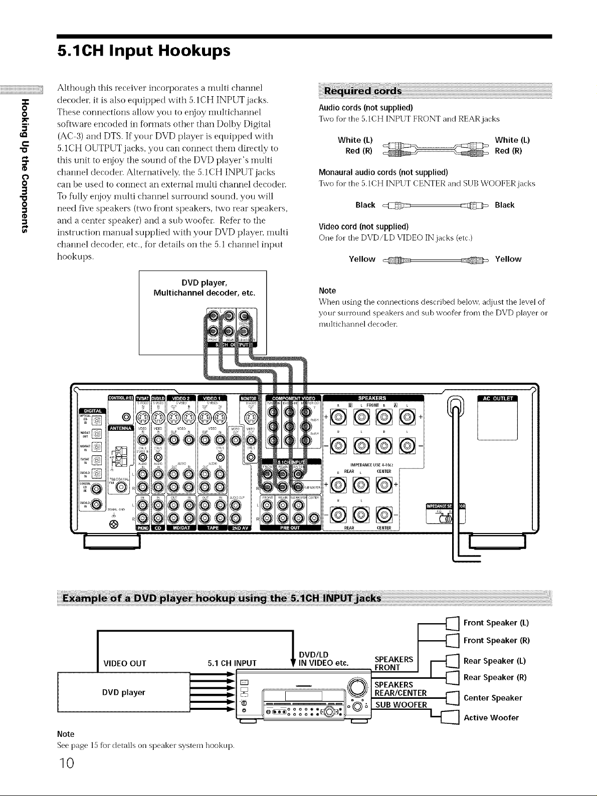
5.1CH Input Hookups
Although this receiver incorporates a nmlti channel
O
O
5'
c
"o
O
O
3
O
decodel, it is also equipped with 5.1CH INPUT jacks.
These connections allow you to enjoy imfltichannel
software encoded in f_rTnats other than Dolhy Digital
(AC-3) and DTS. If your DVD player is equipped with
5.1CH OUTPUT jacks, you can connect them directly to
this unit to enjoy the sound of the DVD player's nmlti
channel decodel_ Alternatively, ti_e 5. I CH INPUT jacks
can he used to connect an external inulti channel decodel_
To fully enjoy multi channel surround sound, you will
need five speakers (two ti'ont speakers, two rear speakers,
and a center speaker) and a sub woofer Refer to the
instruction manual supplied with your DVD player, nmlti
channel decodeL etc., for details on the 5.1 channel input
hookups.
Audio cords (not supplied)
%vo for the 5.1CH INPUT FRONT and REAR jacks
White (L) ._¢_ .-_ White (L)
Red (R) _ Red (R)
Monaural audio cords (not supplied)
Two for the 5.1CH INPUT CENTER and SUB WOOFER jacks
Black @ _ Black
Video cord (not supplied)
One fur the DVD/LD VIDEO IN jacks (etc.)
Yellow Yellow
DVD player,
Multichannel decoder, etc.
S
@
©
®
@
Note
When using the connections described belov[] adjust the level of
your sun'ound speakers and sub woofer fl'om the DVD player or
multichannel decoder.
[] t FRONT _ _ L
+@@@@
-@@@@
I
VIDEO OUT 5.1 CH INPUT IN VIDEO etc. SPEAKERS
I
I
Note
See page 15 f}ar details on speaker system hookup.
DVD player _ REAR/CENTER
I SUB WOOFER
10
i°
I DVD/LD
FRONT
SPEAKERS
-_[_] Front Speaker (L)
-_[_] Front Speaker (R)
[_ Rear Speaker (L)
_[_ Active Woofer
Rear Speaker (R)
[_] Center Speaker
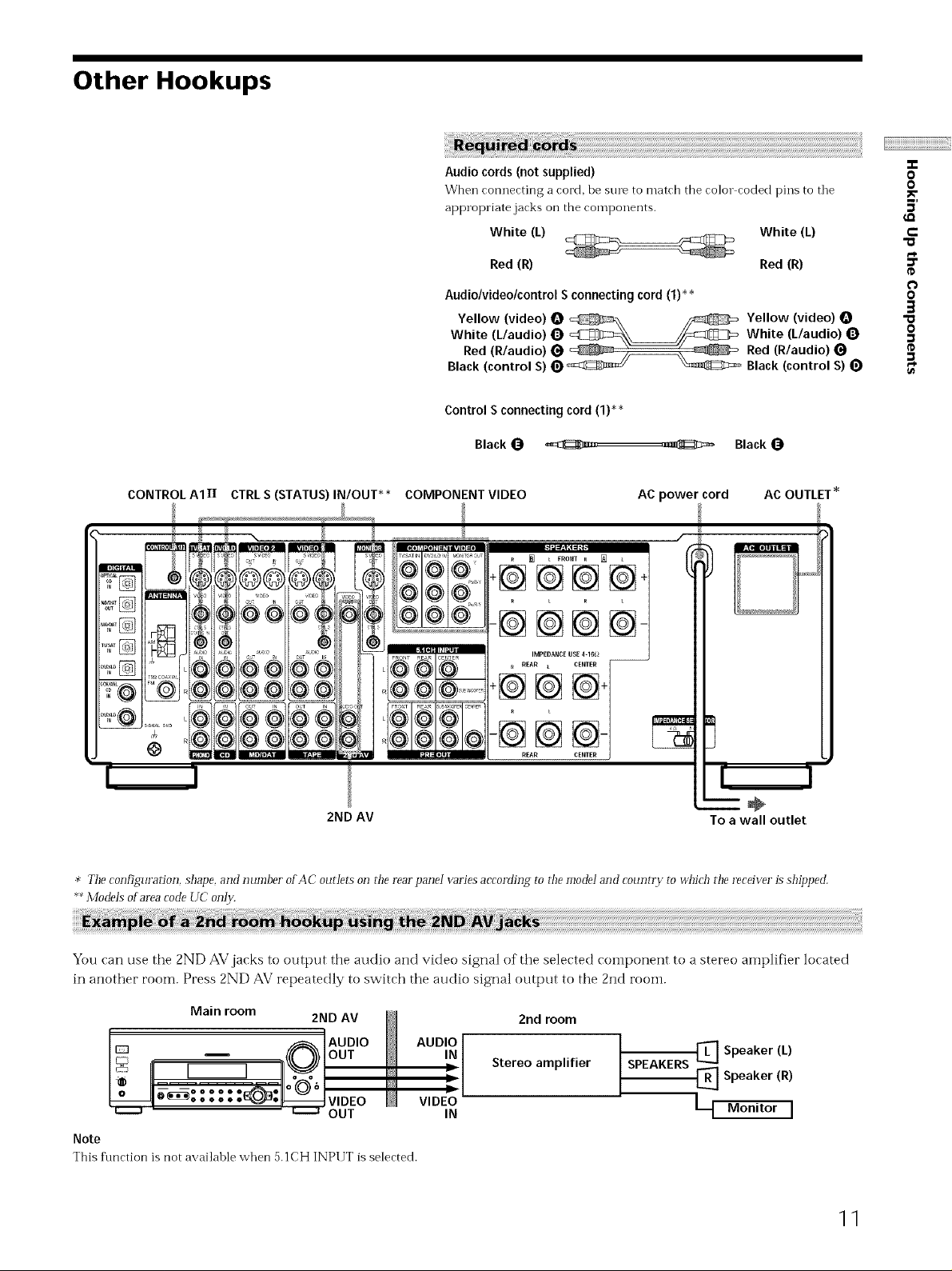
Other Hookups
Red (R) Red (R)
-T-
O
O
5'
e-
"o
e_
Audio/video/control S connecting cord (1)**
Yellow (video) O _ED::_\ _ Yellow (video)
White (L/audio) Q _\_/_mZ]_ White (L/audio) Q
Red (R/audio) _ _ _ _ Red (R/audio)
Black (control S) _ _ _ Black (control S)
Control S connecting cord (1)*_
Black _ ._zll,,, ,,_1_{_3::::_ Black
CONTROL AIII CTRL S (STATUS) IN/OUT _* COMPONENT VIDEO AC power cord AC OUTLET _
-@@@@-
IMPEDANCE USE 4-16_ --
R REAR L CENTER
-@@
REAR
O
3
"a
o
2ND AV
* The configuration, shape, and number o_AC ourlers on r!_erearpanei varies according ro r!_emode! and CO[_I_y r rO ud_ich rim receiver is shil)ped.
Models o_ area code UC only,
÷
To a wall outlet
You can use the 2ND AV jacks to output the audio and video signal of the selected component to a stereo amplifier located
in another room. Press 2ND AV repeatedly to switch the audio signal output to the 2nd rooi'n.
Main room
2ND AV 2nd room
AUDIO
IN
Stereo amplifier
OUT IN
VIDEO
SPEAKERS [_] Speaker (L)
N Speaker (R)
[--t Monitor I
Note
This flmction is not availahle when 5.1CH INPUT is selected.
11
"T-
O
0
5'
r-
"O
e_
o
o
3
"a
o
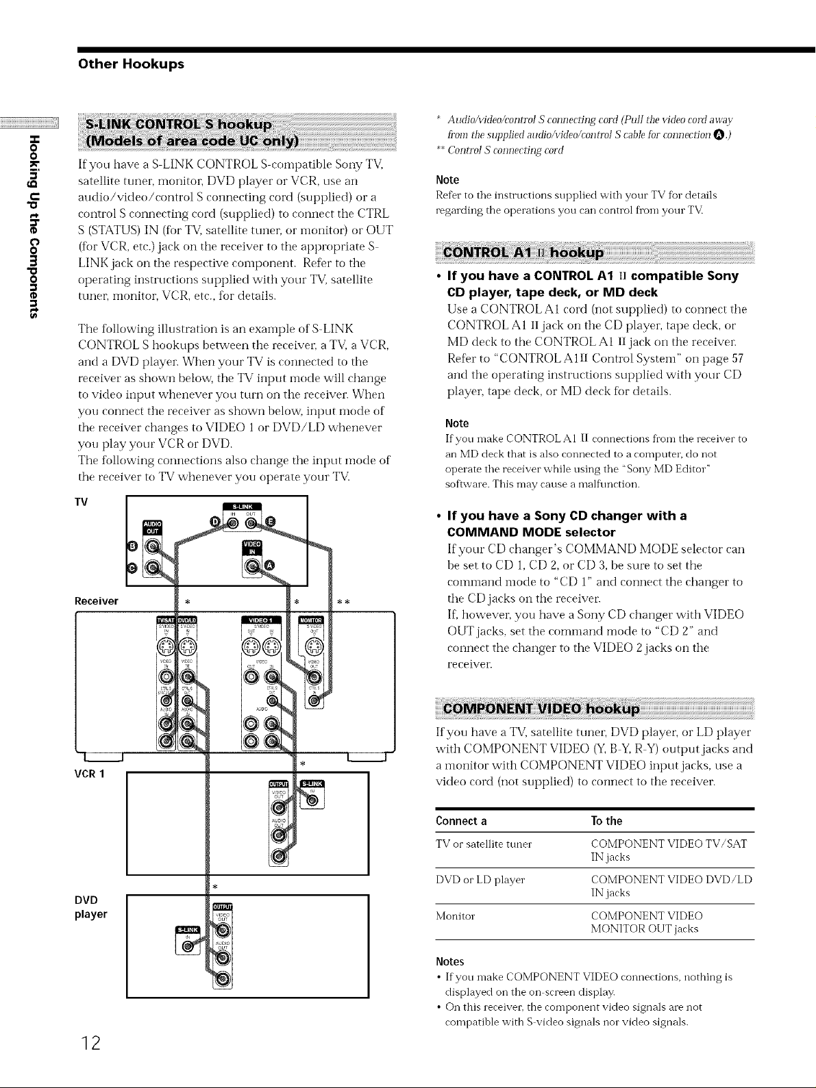
Other Hookups
If you have a S LINK CONTROL S compatible Sony TV,
satellite tuner, monitoi; DVD player or VCR, use an
audio/video/control S connecting cord (supplied) or a
control S connecting cord (supplied) to connect the CTRL
S (STATUS) IN (for TV, satellite tunei; or illonitor) or OUT
(tor VCR, etc.) jack on the receiver to tile appropriate S
LINK jack on tile respective component. Refer to the
operating instructions supplied with your TV. satellite
ttmet; monitor, VCR, etc., for details.
The following illustration is an exainple of S-LINK
CONTROL S hookups between the receiver, a TV, a VCR,
and a DVD player. When your TV is connected to the
receiver as shown below, the TV input inode will change
to video input whenever you turn on the receiver. When
you connect the receiver as shown below, input mode of
the receiver changes to VIDE() 1 or DVD/LD whenever
you play your VCR or DVD.
The following connections also change tile input mode of
the receiver to TV whenever you operate your TV.
* AudioAddeo/controI S connecting cord (Pull the video cord away
fi_omthe supplied audio/video/control S cable [bl connection O.)
**Control S connecrh N cord
Note
Refer to the instructions supplied with your TV for details
regarding the operations you can control from your TV.
• If you have a CONTROL A1 II compatible Sony
CD player, tape deck, or MD deck
Use a CONTROL A1 cord (not supplied) to cormect the
CONTROL A1 II jack on the CD player, tape deck, or
MD deck to the CONTROL AI 11jack on the receive1:
ReDr to "CONTROL A 111Control System" on page 57
and the operating instructions supplied with your CD
player, tape deck, or MD deck for details.
Note
If you make CONTROL A1 II connections from the receiver to
an MD deck that is also connected to a compute1; do not
operate the receiver while using the "Sony MD Editor"
soflwm e. This may cause a malt\ruction.
Tv
Receiver
rE0
i i
VCR1
DVD
player
• If you have a Sony CD changer with a
COMMAND MODE selector
If'your CD changer's COMMAND MODE selector can
be set to CD 1, CD 2, or CD 3, be sure to set tile
comllland illode to "CD 1" and connect the changer to
tile CD jacks on the receivel:
IL however, you have a Sony CD changer with VIDEO
OUT jacks, set the command mode to "CD 2" and
connect the changer to tile VIDEO 2jacks on the
receiver.
If you have a TV. satellite tunel; DVD playel; or LD player
with COMPONENT VIDE() (Y, B Y, R-Y) output jacks and
a monitor with COMPONENT VIDE() input jacks, use a
video cord (not supplied) to connect to the receiver.
Connect a To the
TV or satellite tuner COMPONENT VIDEO TV/SAT
IN jacks
DVD or LD player COMPONENT VIDEO DVD/LD
IN jacks
Monitor COMPONENT VIDEO
MONITOR OUT jacks
12
Notes
• Ifyou inake COMPONENT VIDEO ronnertions, nothing is
displayed on the on screen display.
• On this receiver, the component video signals are not
compatible with S video signals nor video signals.
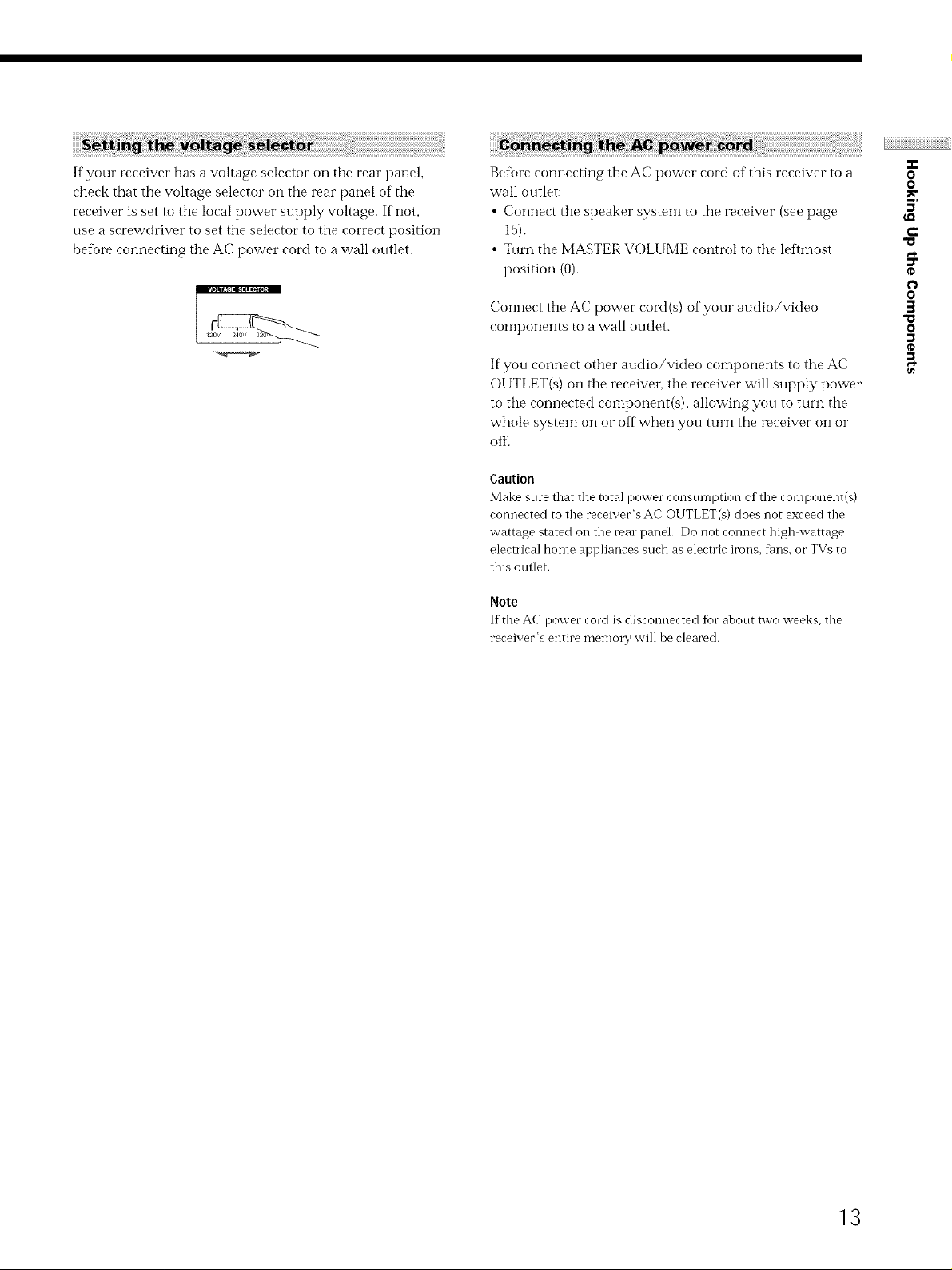
If your receiver has a voltage selector on the rear panel,
check that the voltage selector on the rear panel of the
receiver is set to the local power supply voltage. If not,
use a screwdriver to set the selector to the correct position
before connecting the AC power cord to a wall outlet.
Beff)re connecting the AC power cord of this receiver to a
wall outlet:
• Connect tire speaker system to the receiver (see page
15).
• Turn tire MASTER VOLUME control to the leftmost
position (0).
Connect tire AC power cord (s) of your audio/video
components to a wall outlet.
If you connect other audio/video components to the AC
OUTLET(s) on tire receiver, tire receiver will supply power
to tire connected component(s), allowing you to turn tire
whole system on or off when you turn the receiver on or
off..
Caution
Make sure that the total power consumption of the component(s)
connected to the receiver's AC OUTLET(s) does not exceed the
wattage stated on the rear panel. Do not connect high wattage
electrical home appliances such as electric irons, fans, or TVs to
this outlet.
Note
If the AC power cord is disconnected for about two weeks, the
receiver's entire memory will be cleared.
-r
0
0
3'
t-
O
0
]
"a
o
13
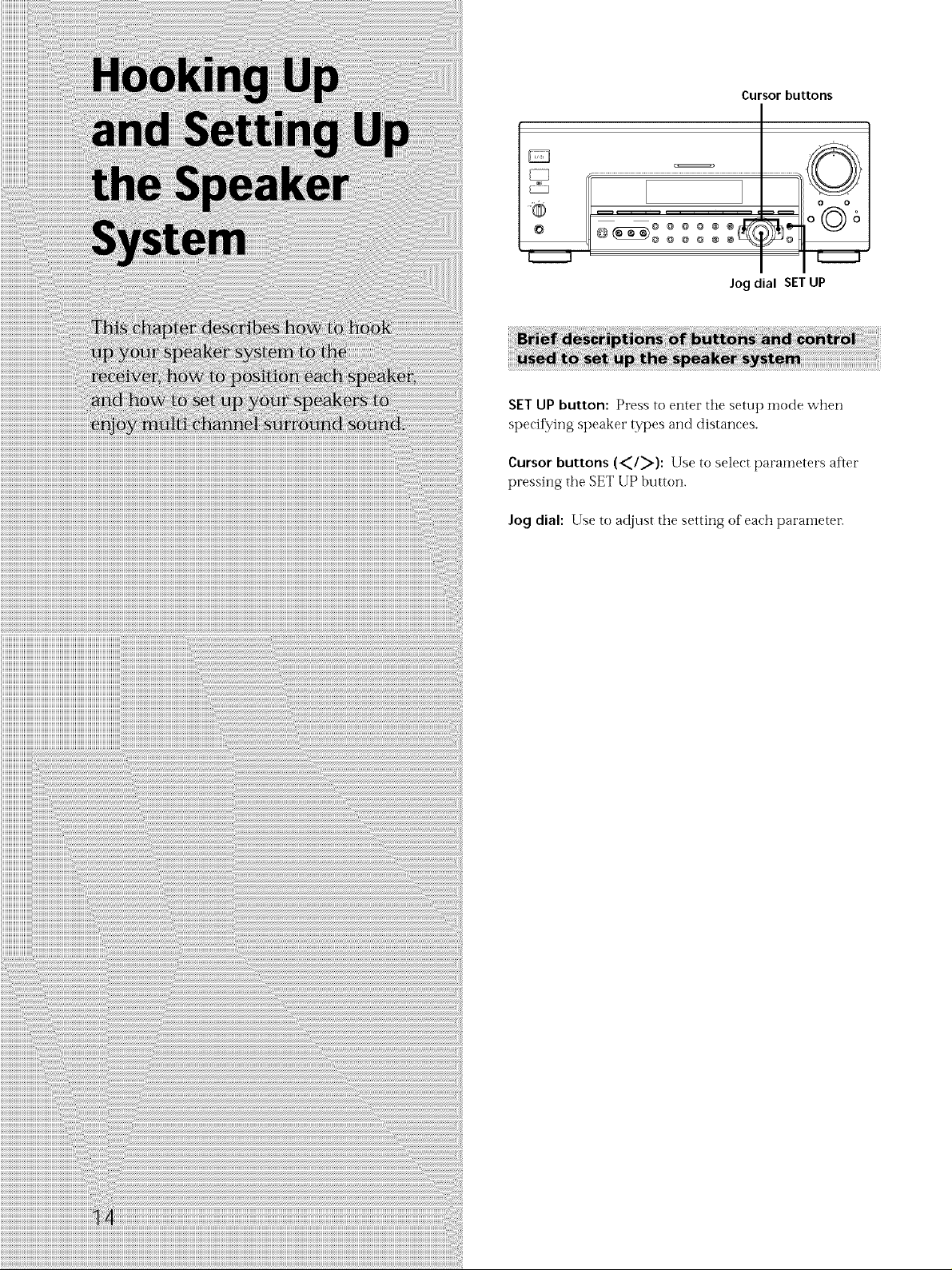
Cursor buttons
©
Jog dial SET UP
SET UP button: Press to enter the setup mode when
specifying speaker types and distances.
Cursor buttons (_I_): Use to select paralneters after
pressing the SETUP button.
Jog dial: Use to adjust the setting of each parameter.
Speaker System Hookup
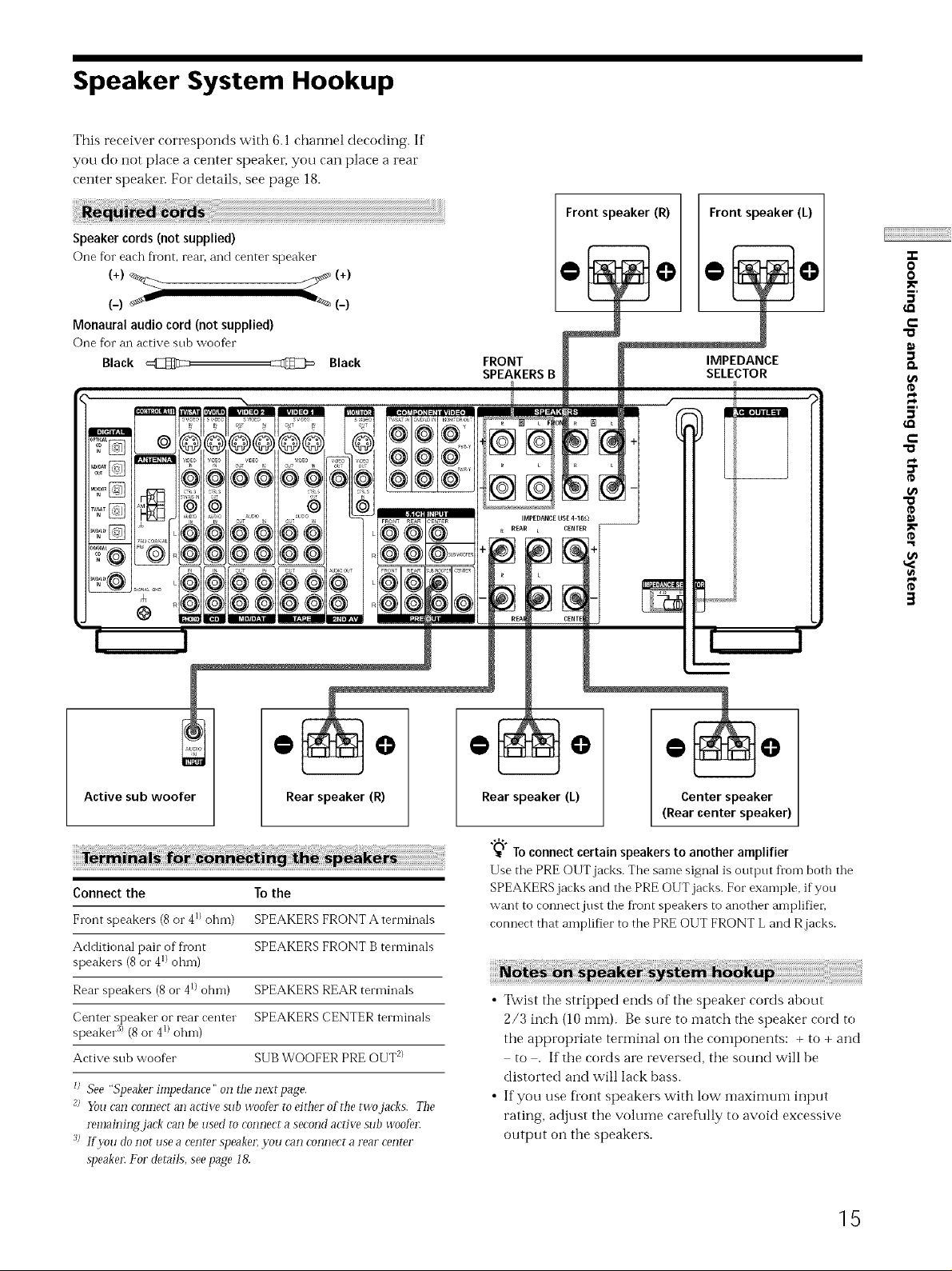
This receiver corresponds with 6. l channel decoding. If
you do not place a center speaker, you can place a rear
center speaker. For details, see page 18.
Speakercords (notsupplied)
COnefbr each fiont, reai. and center speaker
(+)_ _ (+)
(-) _ _ (-)
Monaural audio cord (notsupplied)
One for an active sub woofer
Black _ _ Black
FRONT
SPEAKERS B
@
@
IMPEDANCE USE 4-I _)
R REAR L CENT£R
Front speaker (R)
Front speaker (L)
IMPEDANCE
SELECTOR
"o
"o
"o
O
O
5'
r-
D.
€0
5'
r-
€0
¢D
_0
@ @
Active sub woofer
Connect the To the
Front speakers (8or 4_)ohm) SPEAKERS FRONT A terminals
Additional pair of fi'ont SPEAKERS FRONT B terminals
speakers (8 or 41)ohm)
Rear speakers (8 or 41)ohm) SPEAKERS REAR terminals
Center speaker or rear center SPEAKERS CENTER terminals
speaker :_)(8 or 4_)ohm)
Active sub woofer SUBWOOFER PRE OUT _)
_) See "Speaker impedance" on d_enex_ page.
_) You can connect an active sub woofer to either of the _woja&s. The
remainiz_gjack can be used ro connect a second active sub woofe1:
J> If ?vu do not use a center speaker; ?_)u can connect a rear center
speaker: For derails, see page !&
Rear speaker (R)
@ @
Rearspeaker (L)
"_;_To connect certain speakers to another amplifier
Use the PRE OUT jacks. The same signal is output fl'om both the
SPEAKERS jacks and the PRE OI,IT jacks. For example, if you
want to connectjust the front speakers to another amplifier,
connect that amplifier to the PRE OUT FRONT L and R jacks.
• Twist the stripped ends of the speaker cords about
2/3 inch (10 ram). Be sure to match the speaker cord to
the appropriate terminal on the components: + to + and
to . If the cords are reversed, the sound will be
distorted and will lack [)ass.
• If you use fl'ont speakers with low maximum input
rating, adjust the wdume caref\flly to awfid excessive
output on the speakers.
@ @
Center speaker
(Rearcenter speaker)
15
Speaker System Hookup
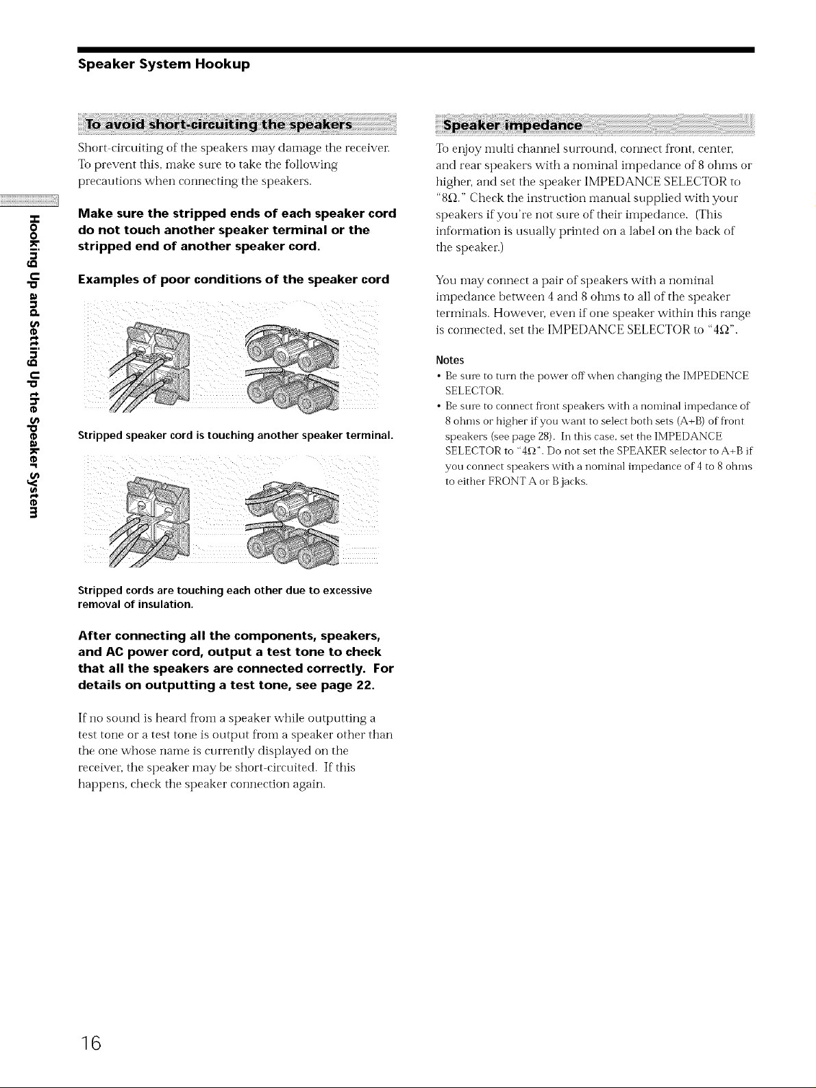
Short circuiting of the speakers inay damage the receiver.
To prevent this, make sure to take the following
precautions when connecting tile speakers.
-r
0
0
5'
c
Make sure the stripped ends of each speaker cord
do not touch another speaker terminal or the
stripped end of another speaker cord.
Examples of poor conditions of the speaker cord
5'
c
Stripped speaker cord is touching another speaker terminal.
To enjoy inulti channel surrotn-ld, connect front, center,
and rear speakers with a nominal impedance of 8 ohms or
highei, and set the speaker IMPEDANCE SELECTOR to
"8_-_."Check tile instruction manual supplied with your
speakers if you're not sure of their iinpedance. (This
infi_rmation is usually printed on a label on tile back of
the speaker.)
You may connect a pair of speakers with a nominal
impedance between 4 and 8 ohms to all of the speaker
terminals. Howeven even if one speaker within this range
is c(mnected, set tile IMPEDANCE SELECTOR to "4_-_".
Notes
• Bestnv to turn the power offwhen changing the IMPEDENCE
SELECTOR.
• Bestnv to connect Dont speakers with a nominal impedance of
8 ohms or higher ifyou want to select both sets (A+B) of Dont
speakers (see page 28). In this case. set the IMPEDANCE
SELECTOR to "4£_".Do not set the SPEAKER selector to A+B if
you connect speakers with a nominal impedance of 4 to 8 ohms
to either FRONT A or B jacks.
3
Stripped cords are touching each other due to excessive
removal of insulation,
After connecting all the components, speakers,
and AC power cord, output a test tone to check
that all the speakers are connected correctly. For
details on outputting a test tone, see page 22.
If no sound is heard ti"om a speaker while outputting a
test tone or a test tone is output ti'om a speaker other than
the one whose name is currently displayed on tile
receiver, the speaker may be short-circuited. If this
hapt)ens, check the speaker connection again.
16
Performing Initial Setup Operations
Once you have hooked up the speakers and turned on the
power, clear the receiver's memm_. Then specif,/the
speaker parameters (size, position, etc.) and perfbml any
other initial setup operations necessary fbr your system.
Make sure that you have:
• Turned MASTER VOLUME to the leftmost position (0).
• Selected the appropriate front speakers (see "[]
SPEAKERS selector" on page 28).
Beff_re using your receiver fbr the first time, or when you
want to cleat" the receiver's llleiilory, do the following.
Beff_re using your receiver fbr the first time, use the SET
UP button to adjust the setup parameters so that they
correspond to your system. You can adjust the fbllowing
items. For details on how to make adjustments, see the
page in parenthesis.
Video power inanagement (page 55).
Whether other components will turn on or off
• 2 way remote control system operation (page 56).
• Selecting the coillilland mode (page 56).
• Select the TV color system of the monitor (except for
• Selecting the color of the on-screen display (page 56).
©
.... oo
"®© o_6
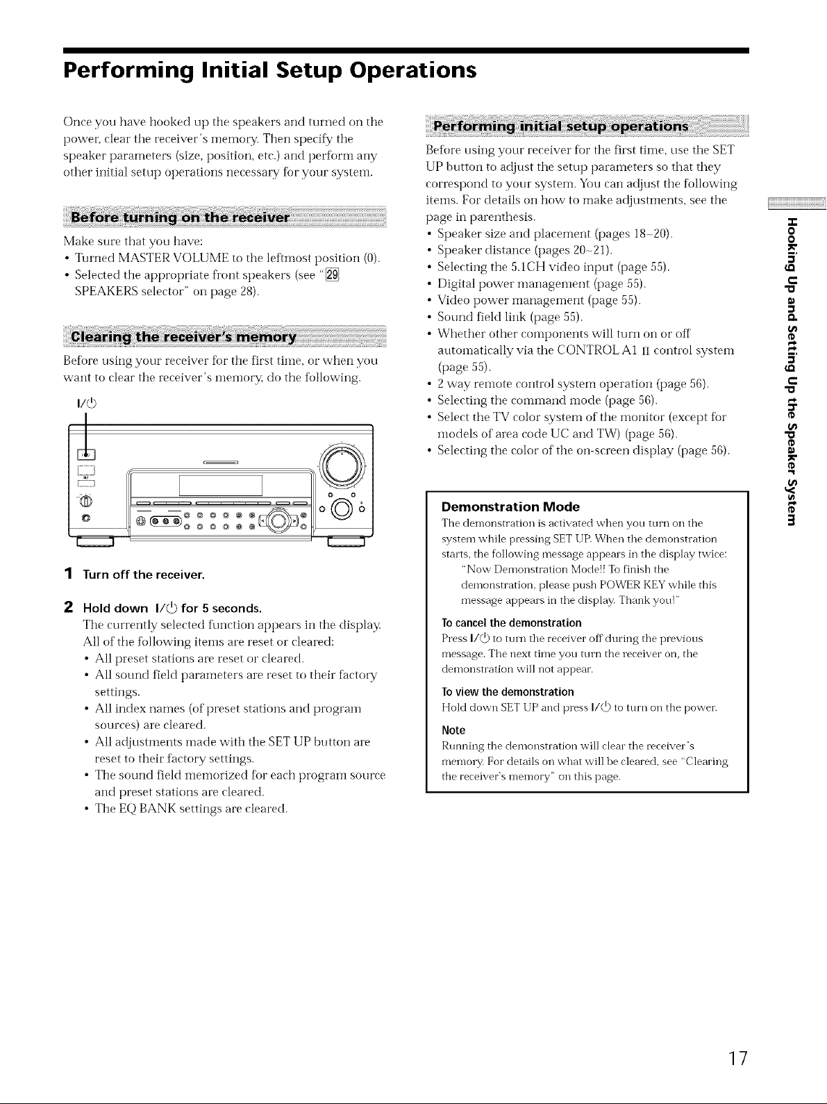
1 Turn off the receiver.
Hold down I/@ for 5 seconds.
The currently selected f\mction appears in the display.
All of the tbllowing items are reset or cleared:
• All preset stations al_ reset or cleared.
• All sound field parameters are reset to their factoL'y
• All index names (of preset stations and program
• All adjustments made with the SET UP btlt[oi? are
• The sound field memorized fl_r each program source
• The EQ BANK settings are cleared.
@_ ooo_ o
settings.
sources) are cleared.
reset to their factory settings.
and preset stations are cleared.
Speaker size and placement (pages 18-20).
Speaker distance (pages 20-21).
Selecting the 5.1CH video input (page 55).
Digital power management (page 55).
Sound field link (page 55).
atttomatically via the CONTROL A1 iI control system
(page 55).
models of area code UC and TW) (page 56).
Demonstration Mode
The demonstration is activated when you turn on the
system while pressing SET UR When the demonstration
starts, the following message appears in the display twice:
"Now Demonstration Mode!! To finish the
demonstration, please push POWER KEY while this
message appears in the display. Thank you!"
To cancel the demonstration
Press I/@ to turn the receiver off during the previous
message. The next time you mrn the receiver on, the
demonstration will not appear.
To view the demonstration
Hold down SET UP and press I/(,!) to turn on the power.
Note
Running the demonstration will clear the receiver's
memory. For details on what will be cleared, see "Clearing
the receiver's memory" on this page.
o
o
5'
€-
"a
5'
€-
"a
"o
o
t_
o
g
3
17
Multi Channel Surround Setup
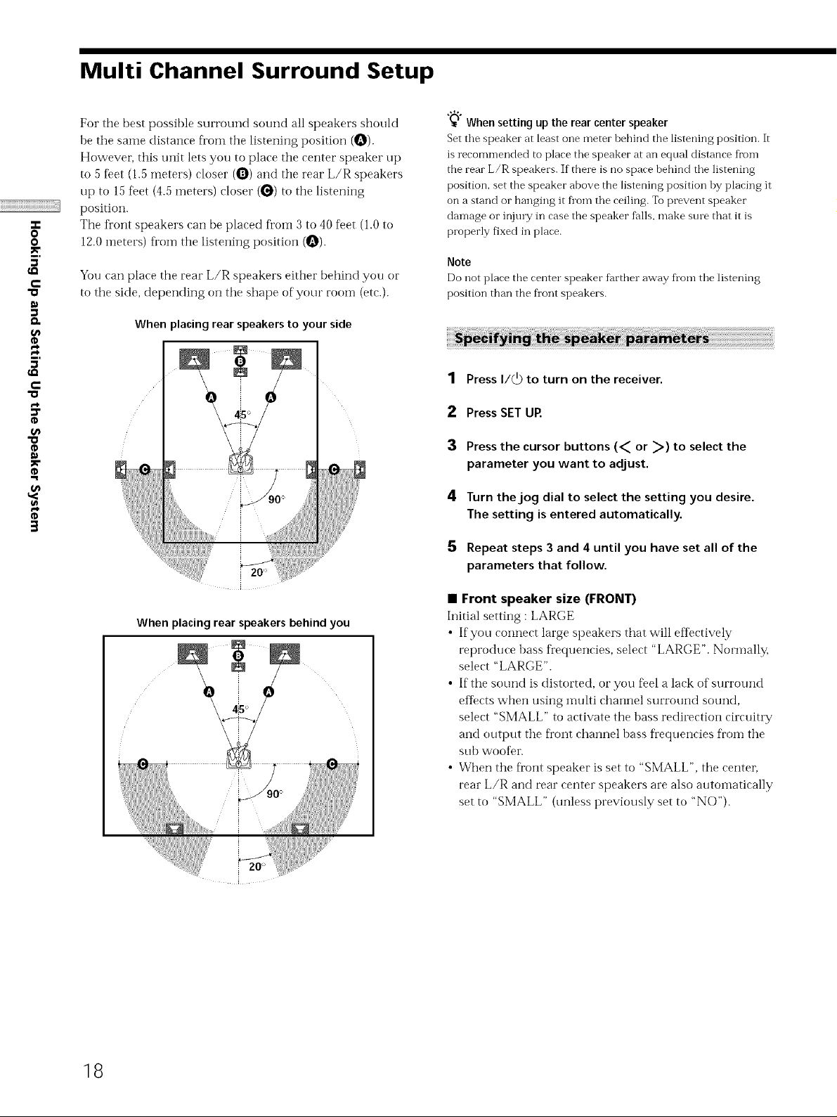
For the best possible surround sound all speakers should
be the same distance Kom the listening position (O).
However, this unit lets you to place the center speaker up
to 5 %et (1.5 meters) closer (O) and the rear L/R speakers
up to 15 %et (4.5 meters) closer (_) to the listening
position.
q.
0
0
The front speakers can be placed fl'oin 3 to 40 feet (1.0 to
12.0 meters) fl'om the listening position {O).
5'
c
5'
c
You can place the rear L/R speakers either behind you or
to the side, depending on the shape of your room (etc.).
When placing rear speakers to your side
l
ic
3
"_"_Whensetting upthe rear centerspeaker
Set the speaker at least one meter bebind the listening position. It
is recommended to place the speaker at an equal distance from
the rear L/R speakers. If there is no space behind the listening
position, set the speaker above the listening position by placing it
on a stand or hanging it fl'om the ceiling. To prevent speaker
damage or injmT in case the speaker falls, make sine that it is
properly fixed in place.
Note
Do not place tbe center speaker farther away fl'om the listening
position than the fl'ont speakers.
1 Press I/_) to turn on the receiver.
2 Press SET UR
3 Press the cursor buttons (_ or _) to select the
parameter you want to adjust.
4 Turn the jog dial to select the setting you desire.
The setting is entered automatically.
5 Repeat steps 3 and 4 until you have set all of the
parameters that follow.
When placing rear speakers behind you
0 0
• Front speaker size (FRONT)
Initial setting : LARGE
• If you connect large speakers that will eflk_ctively
reproduce bass frequencies, select "LARGE". Nommlly,
select "LARGE".
• If the sound is distorted, or you %el a lack of surround
efIects when using multi channel surround sound,
select "SMALL" to activate the bass redirection circuitry
and output the fl'ont channel bass frequencies fl'om the
sub wooDr.
• When the Dont speaker is set to "SMALL", the centeL
rear L/R and rear center speakers are also autoinatically
set to "SMALL" (unless previously set to "NO").
18
• Center speaker size (CENTER)
Initial setting : LARGE
• ffyou eonneet a large speaker that will eftbctively
reproduce bass frequencies, select "LARGE". Normally,
select "LARGE". Howeven if the fi'ont speakers are set
to "SMALL", you cannot set the center speaker to
"LARGE".
• If the sound is distorted, or you feel a lack of surround
eftects when using nmlti channel surround sound,
select "SMALL" to activate the bass redirection circuitry
and OUtl)Ut the center channel bass fi'equencies fi'om the
front speakers (if set to "LARGE") or sub woofer..1
• If you do not connect a center speaker, select "NO". The
sound of the center channel will be output fi'om the
fi'ont speakers.*2
• Rear L/R speaker size (REAR I/R)
Initial setting : LARGE
• If you connect large speakers that will eflbctively
reproduce bass frequencies, select "LARGE". Normally,
select "LARGE". Howeven if the fi'ont speakers are set
co "SMALL", you cannot set the rear L/R speakers to
"LARGE".
• If the sound is distorted, or you feel a lack of surround
efIects when using nmlti channel surround sound,
select "SMALL" to activate the bass redirection circuitry
and outt)ut the rear channel bass frequei_cies fi'oln the
sub wootbr or other "LARGE" speakers.
• If you do not connect rear L/R speakers, select "NO". *:_
"_'°N"1_'3 correspond to the following Dolby Pro Logic modes
1 NORMAL
•2 PHANTOM
•3 3 STEREO
• Rear center speaker size (REAR CTR)*
Initial setting : NO
This parameter ean be set when the eenter speaker is set to
"NO" and the rear speakers are set to "LARGE" or
"SMALL". This setting is effective when NORMAL
SURROUND or VIRTUAL MATRIX 6.1 is selected.
• If you connect a large speaker that will etIectively
reproduce bass fi'equencies, select "LARGE". Normally,
select "LARGE". However, if the fi'ont speakers are set
to "SMALL", you cannot set the rear center speaker to
"LARGE".
• If the sound is distorted, or you Del a lack of surround
effbcts when using imflti channel surround sound,
select "SMALL" to activate the bass redirection circuitry
and outt)ut the center channel bass fl'equencies froin the
fi'ont speakers (ifset to "LARGE") or sub woofen
However, if' the rear L/R speakers are set to "SMALL",
the rear center speaker is automatically set to "SMALL".
• If you do not connect a rear center speaken select "NO".
* This parameter is not available when "Rear L/R
speaker size (REAR L/R)" is set to "NO".
*>R
N'° About speaker sizes (LARGE and SMALL)
Internally, the LARGE and SMALL settings fbr each speaker
determine whether or not the internal sotmd processor will cut
the hass signal fl'om that channel. Wben the hass is cut fi'om a
channel, the hass redirection circuitry sends the corresponding
bass fi equencies to the sub woofer or other 'LARGE" speakers.
Howeven since bass sounds have a certain amount of
directionality, it best not to cut them, if"possihle. Therefore, even
when using small speakers, you can set them to "LARGE" if you
want to output the hass frequencies fi'om that speaker. On the
other band, if you are using a large speaker, but prefer not to
have bass fi eqnencies output fi'om that speaker, set it to
"SMALL".
If the overall sound level is lower than you prefer, set all speakers
to "LARGE". If there is not enough bass, you can use the
equalizer to boost the bass levels. To adjust the eclnalizei; see
page 39.
"a
=)=
o
o
)e
5'
€-
o
5'
€-
0
o
o
3
19
Multi Channel Surround Setup
• Sub woofer selection (SUB WOOFER)
Initial setting : YES
• If you connect a sub woot_r, select "YES".
• If you do not connect a sub woofel; select "NO". This
activates the bass rediiection circuitry and outputs the
LFE signals fi'om other speakers.
q.
O
O
5'
c
"a
Q,
5'
c
"a
"o
• In order to take full advantage of the Dolby Digital
(AC 3) bass redirection circuitrN we recommend setting
the sub woofer's cut off fi'equency as high as possible.
• Front speaker distance (FRONT)
Initial setting : 16 fleet* (5.0 meter)
Set the distance fl'om your listening position to the fl'ont
(left or right) speaker (_ on page 18).
• Front speaker distance can be set in 1 foot* (0.1 ineter)
steps fl'om 3 to 40 fleet* (1.0 to 12.0 meters).
• If both speakers are not placed an equal distance flom
your listening position, set the distance to the closest
speaker.
* Models of area code UC only.
• Center speaker distance (CENTER)
Initial setting : 16 %et* (5.0 meter)
Set the distance fl'om your listening position to tile center
3
speaker
• Center speaker distance can be set in 1 foot* ((/.1 meter)
steps fl'om a distance equal to the front speaker distance
(_ on page 18) to a distance 5 feet* (1.5 meters) closer to
your listening position (_ on page 18).
• Do not place the center speaker farther away fl'om your
listening position than the fl'ont speakers.
* Models of area code UC only.
• Rear L/R speaker distance (REAR L/R)
Initial setting : 11 fieet* (3.5 meter)
Set the distance fl'om your listening position to the mar
(left or righ0 speaker.
• Real" L/R speaker distance can be set in 1 foot*
(0.1 meter) steps fl'om a distance equal to the fl'ont
speaker distance (_ on page 18) to a distance 15 feet*
(4.5 meters) closer to your listening position (_ on page
18).
• Do not place the rear L/R speakers farther away fl'om
your listening position than tile fl'ont speakers.
• If both speakers are not placed an equal distance flom
your listening position, set the distance to the closest
speaker.
* Models of area code UC only.
• Rear center speaker distance (REAR CTR)
Initial setting : 11fleet* (3.5 meter)
Set the distance f'rom your listening position to the rear
center speaker.
• Rear center speaker distance can be set in 1 foot*
(0.1 meter) steps fl'om a distance equal to tile fi'ont
speaker distance (O on page 18) to a distance 15 feet*
(4.5 meters) closer to your listening position (_ on page
18).
• Do not place the rear center speaker farther away from
your listening position than the front speakers.
* Models of area code UC only.
"_" About speaker distances
This trait allows you to input tbe speaker position in terms of
distance. However, it is not possible to set the center speaker
further than the fl'ont speakers. Also, the center speaker cannot be
set more that 5 feet* (1.5 meters) closer than the fl'ont speakers.
Likewise, the rear L/R speakers can not be set farther away from
the listening position than the fl'ont speakers. And they can be no
more than 15 feet* (4.5 meters) closei:
This is because incorrect speaker placement is not conducive to
the enjoyment of surround sound.
Please note that, setting the speaker distance closer than the
actual location of the speakers will cause a delay in the output of
tbe sound fl'om that speakei: In other words, the speaker will
sound like it is farther away.
For example, setting the center speaker distance 3-6 feet* (1 -2 m)
closer than the actual speaker position will create a fairly realistic
sensation of'being 'inside" tbe screen. If you cannot obtain a
satisfactory surround eftect because the rear L/R speakers are too
close, setting the rear L/R speaker distance closer (shorter) than
the actual distance will create a larger soundstage.
Adjusting these parameter while listening to the sound often
results in much better surround sound. Give it a try!
Models of area code UC only.
2O
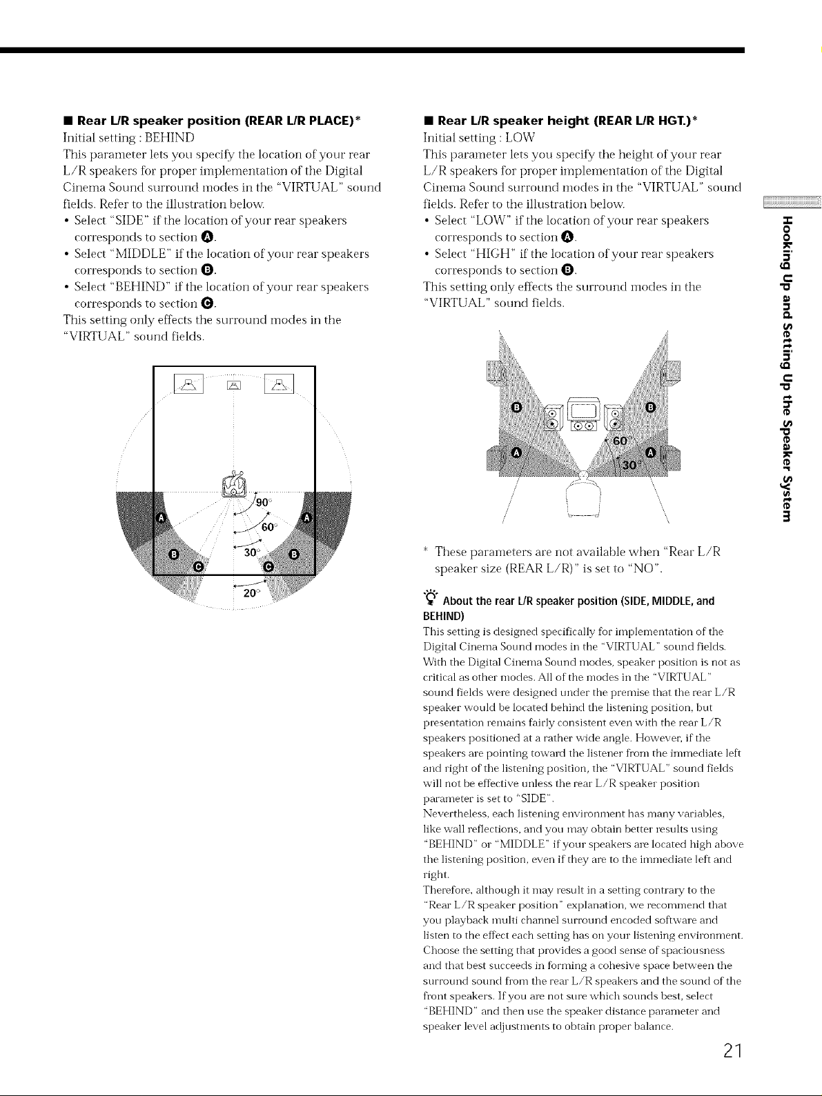
• Rear L/R speaker position (REAR L/R PLACE)*
Initial setting : BEHIND
This parameter lets you speeifk/tile location of your rear
L/R speakers fbr proper implementation of the Digital
Cinema Sound surround modes in tile "VIRTUAL" sound
fields. Refer to the illustration helow.
• Select "SIDE" if the location of your rear speakers
corresponds to section O.
• Select "MIDDLE" if the location of your rear speakers
corresponds to section Q.
• Select "BEHIND" if the location of your rear speakers
corresponds to section Q.
This setting only effects the surround modes in the
"VIRTUAL" sound fieMs.
• Rear L/R speaker height (REAR L/R HGT.)*
Initial setting : LOW
This parameter lets you speeii_y the height of your rear
L/R speakers tbr proper implelnentation of tile Digital
Cinema Sound surround modes in the "VIRTUAL" sound
fields. Refer to tile illustration below.
• Select "LOW" if the location of your rear speakers
corresponds to section O.
• Select "HIGH" if the location of your real" speakers
corresponds to section O.
This setting only effects tile surround i-nodes in the
"VIRTUAL" sound Belds.
/
/
/
/
/
i
J
",,,
O
O
5'
€-
5'
€-
"0
O
o
g
3
* These paraineters are not available when "Real" L/R
speaker size (REAR L/R)" is set to "NO".
_" About the rear UR speaker position (SIDE, MIDDLE, and
BEHIND)
This setting is designed specifically for implementation of the
Digital Cinema Sound modes in the "VIRTUAL" soui'_d fields.
With the Digital Cinema Sound modes, speaker position is not as
critical as other modes. All of the modes in the "VIRTUAL"
sound fields were designed under the premise that the rear L/R
speaker would he located behind the listening position_ but
presentation remains fhirly consistent even with the rear L/R
speakers positioned at a rather wide angle. Howeven if the
speakers are pointing toward the listener from the immediate left
and right of the listening position, the "VIRTUAL" sound fields
will not be effective unless the rear L/R speaker position
parameter is set to "SIDE".
Nevertheless, each listening environment has many variables,
like wall reflections, and you may obtain better results using
"BEHIND" or "MIDDLE" if your speakers are located high above
the listening position, even if they are to the inm-lediate left and
right.
Therefore, although it may result in a setting contrary to the
"Rear L/R speaker position" explanation, we recommend that
you playback n'_ulti channel surroui'_d encoded software and
listen to the eff)ct each setting has on your listening environment.
Choose the setting that provides a good sense of spaciousness
and that best succeeds in fiarming a cohesive space between the
surroui'Jd souiKt flon'J the rear L/R speakers and the sound of the
front speakers. If you are not sure which sounds best, select
"BEHIND" and then use the speaker distance parameter and
speaker level adjustments to obtain proper balance.
21
 Loading...